JP5967971B2 - Manufacturing method of electric motor - Google Patents
Manufacturing method of electric motor Download PDFInfo
- Publication number
- JP5967971B2 JP5967971B2 JP2012033915A JP2012033915A JP5967971B2 JP 5967971 B2 JP5967971 B2 JP 5967971B2 JP 2012033915 A JP2012033915 A JP 2012033915A JP 2012033915 A JP2012033915 A JP 2012033915A JP 5967971 B2 JP5967971 B2 JP 5967971B2
- Authority
- JP
- Japan
- Prior art keywords
- varnish
- winding
- stator
- electric motor
- compressor
- Prior art date
- Legal status (The legal status is an assumption and is not a legal conclusion. Google has not performed a legal analysis and makes no representation as to the accuracy of the status listed.)
- Expired - Fee Related
Links
- 238000004519 manufacturing process Methods 0.000 title claims description 24
- 239000002966 varnish Substances 0.000 claims description 226
- 238000004804 winding Methods 0.000 claims description 203
- 238000005470 impregnation Methods 0.000 claims description 81
- 238000000034 method Methods 0.000 claims description 55
- 230000008569 process Effects 0.000 claims description 29
- 230000002093 peripheral effect Effects 0.000 claims description 21
- WABPQHHGFIMREM-UHFFFAOYSA-N lead(0) Chemical compound [Pb] WABPQHHGFIMREM-UHFFFAOYSA-N 0.000 claims description 13
- 239000000203 mixture Substances 0.000 claims description 4
- 230000008859 change Effects 0.000 claims description 3
- 239000003507 refrigerant Substances 0.000 description 46
- 238000005057 refrigeration Methods 0.000 description 26
- 230000004907 flux Effects 0.000 description 15
- 230000006835 compression Effects 0.000 description 12
- 238000007906 compression Methods 0.000 description 12
- 230000007246 mechanism Effects 0.000 description 11
- XAGFODPZIPBFFR-UHFFFAOYSA-N aluminium Chemical compound [Al] XAGFODPZIPBFFR-UHFFFAOYSA-N 0.000 description 7
- 229910052782 aluminium Inorganic materials 0.000 description 7
- 239000002826 coolant Substances 0.000 description 7
- 238000005096 rolling process Methods 0.000 description 7
- 238000001816 cooling Methods 0.000 description 6
- 230000006870 function Effects 0.000 description 6
- 238000009413 insulation Methods 0.000 description 5
- 239000004020 conductor Substances 0.000 description 4
- 239000011521 glass Substances 0.000 description 4
- 230000006698 induction Effects 0.000 description 4
- 239000003921 oil Substances 0.000 description 4
- 229910000831 Steel Inorganic materials 0.000 description 3
- 239000003990 capacitor Substances 0.000 description 3
- 238000010586 diagram Methods 0.000 description 3
- 230000005484 gravity Effects 0.000 description 3
- 239000010959 steel Substances 0.000 description 3
- PPBRXRYQALVLMV-UHFFFAOYSA-N Styrene Chemical compound C=CC1=CC=CC=C1 PPBRXRYQALVLMV-UHFFFAOYSA-N 0.000 description 2
- 230000009471 action Effects 0.000 description 2
- 238000005266 casting Methods 0.000 description 2
- 238000009826 distribution Methods 0.000 description 2
- 235000012489 doughnuts Nutrition 0.000 description 2
- 239000000428 dust Substances 0.000 description 2
- 230000000694 effects Effects 0.000 description 2
- 238000010030 laminating Methods 0.000 description 2
- 239000007788 liquid Substances 0.000 description 2
- 239000010721 machine oil Substances 0.000 description 2
- 239000000463 material Substances 0.000 description 2
- 238000004080 punching Methods 0.000 description 2
- 238000003466 welding Methods 0.000 description 2
- 239000004593 Epoxy Substances 0.000 description 1
- CERQOIWHTDAKMF-UHFFFAOYSA-M Methacrylate Chemical compound CC(=C)C([O-])=O CERQOIWHTDAKMF-UHFFFAOYSA-M 0.000 description 1
- 239000011248 coating agent Substances 0.000 description 1
- 238000000576 coating method Methods 0.000 description 1
- 238000005520 cutting process Methods 0.000 description 1
- 230000006837 decompression Effects 0.000 description 1
- 238000004512 die casting Methods 0.000 description 1
- 238000007599 discharging Methods 0.000 description 1
- 239000003822 epoxy resin Substances 0.000 description 1
- 230000017525 heat dissipation Effects 0.000 description 1
- 238000010438 heat treatment Methods 0.000 description 1
- 239000011810 insulating material Substances 0.000 description 1
- 230000008450 motivation Effects 0.000 description 1
- 230000000149 penetrating effect Effects 0.000 description 1
- 229920000647 polyepoxide Polymers 0.000 description 1
- 229920000728 polyester Polymers 0.000 description 1
- 238000003825 pressing Methods 0.000 description 1
- KCTAWXVAICEBSD-UHFFFAOYSA-N prop-2-enoyloxy prop-2-eneperoxoate Chemical compound C=CC(=O)OOOC(=O)C=C KCTAWXVAICEBSD-UHFFFAOYSA-N 0.000 description 1
- 238000003860 storage Methods 0.000 description 1
- 238000010792 warming Methods 0.000 description 1
- XLYOFNOQVPJJNP-UHFFFAOYSA-N water Substances O XLYOFNOQVPJJNP-UHFFFAOYSA-N 0.000 description 1
Images


Classifications
-
- H—ELECTRICITY
- H02—GENERATION; CONVERSION OR DISTRIBUTION OF ELECTRIC POWER
- H02K—DYNAMO-ELECTRIC MACHINES
- H02K3/00—Details of windings
- H02K3/30—Windings characterised by the insulating material
-
- H—ELECTRICITY
- H02—GENERATION; CONVERSION OR DISTRIBUTION OF ELECTRIC POWER
- H02K—DYNAMO-ELECTRIC MACHINES
- H02K1/00—Details of the magnetic circuit
- H02K1/06—Details of the magnetic circuit characterised by the shape, form or construction
- H02K1/12—Stationary parts of the magnetic circuit
- H02K1/16—Stator cores with slots for windings
-
- H—ELECTRICITY
- H02—GENERATION; CONVERSION OR DISTRIBUTION OF ELECTRIC POWER
- H02K—DYNAMO-ELECTRIC MACHINES
- H02K15/00—Methods or apparatus specially adapted for manufacturing, assembling, maintaining or repairing of dynamo-electric machines
- H02K15/12—Impregnating, heating or drying of windings, stators, rotors or machines
-
- H—ELECTRICITY
- H02—GENERATION; CONVERSION OR DISTRIBUTION OF ELECTRIC POWER
- H02K—DYNAMO-ELECTRIC MACHINES
- H02K3/00—Details of windings
- H02K3/32—Windings characterised by the shape, form or construction of the insulation
- H02K3/34—Windings characterised by the shape, form or construction of the insulation between conductors or between conductor and core, e.g. slot insulation
-
- H—ELECTRICITY
- H02—GENERATION; CONVERSION OR DISTRIBUTION OF ELECTRIC POWER
- H02K—DYNAMO-ELECTRIC MACHINES
- H02K3/00—Details of windings
- H02K3/46—Fastening of windings on the stator or rotor structure
- H02K3/52—Fastening salient pole windings or connections thereto
- H02K3/521—Fastening salient pole windings or connections thereto applicable to stators only
- H02K3/522—Fastening salient pole windings or connections thereto applicable to stators only for generally annular cores with salient poles
Description
本発明は、電動機の製造方法に関するものである。 The present invention relates to a method for manufacturing an electric motor.
従来より、圧縮機の電動機の固定子に巻回された巻線には、巻線の表面を絶縁する目的、巻線をゴミ等から保護する目的、巻回時に傷ついた巻線の表面をコーティングする目的等により、ワニスが含浸されている。例えば、固定子に巻線を巻回した状態で、槽内に貯留されたワニスに巻線を浸漬して巻線にワニスを供給する。これにより、供給されたワニスは、毛細管現象によって巻線に含浸する。また例えば、巻線上にワニスを滴下して供給することにより、供給されたワニスは、毛細管現象によって巻線に含浸する。このような巻線へのワニスの含浸は、大気中で行われることが一般的である。また、巻線へのワニスの含浸方法としては、真空中でワニスを含浸させる方法も従来より提案されている(例えば、特許文献1,2参照)。そして、特許文献3には、真空中でワニスを含浸させることにより、巻線間の狭い空間にまでワニスを含浸させることができ、巻線の熱伝導率が向上することが開示されている。
Conventionally, the winding wound around the stator of a compressor motor is coated with the purpose of insulating the surface of the winding, protecting the winding from dust, etc., and the surface of the wound wound during winding. The varnish is impregnated for some purpose. For example, in a state where the winding is wound around the stator, the winding is immersed in a varnish stored in the tank, and the varnish is supplied to the winding. Thereby, the supplied varnish impregnates the windings by capillary action. Further, for example, by supplying varnish dropwise onto the winding, the supplied varnish impregnates the winding by capillary action. Such impregnation of the varnish into the winding is generally performed in the atmosphere. In addition, as a method for impregnating the varnish into the winding, a method of impregnating the varnish in a vacuum has been proposed (see, for example,
従来より、冷凍サイクル装置には、R410A冷媒よりも吐出温度が約5℃ほど高くなるR22冷媒が用いられることがある。このような吐出温度が高くなる冷媒を冷凍サイクル装置に用いることにより、圧縮機の電動機の固定子に巻回された巻線も、その温度が上昇してしまう。一方、IEC規格(IEC60335−1)には、電動機の巻線温度に関する規格が定められている(例えば、耐熱クラスEの電動機で、巻線温度131℃以下であること)。そこで、R22冷媒を用いる冷凍サイクル装置に使用される圧縮機には、上記IEC規格を満たすため、高い放熱性能が要求される。このため、大気中でワニスを巻線に含浸させた電動機を搭載した圧縮機は、R22冷媒を用いる冷凍サイクル装置に使用される場合、巻線へのワニスの含浸量が不足するために巻線の熱伝導率が十分ではないので、圧縮機が大型化してしまうという問題点があった。 Conventionally, R22 refrigerant whose discharge temperature is higher by about 5 ° C. than R410A refrigerant may be used in the refrigeration cycle apparatus. By using such a refrigerant having a high discharge temperature for the refrigeration cycle apparatus, the temperature of the winding wound around the stator of the compressor motor also rises. On the other hand, the IEC standard (IEC 60335-1) defines a standard related to the winding temperature of an electric motor (for example, a heat resistance class E electric motor having a winding temperature of 131 ° C. or lower). Therefore, a compressor used in the refrigeration cycle apparatus using the R22 refrigerant is required to have high heat dissipation performance in order to satisfy the IEC standard. For this reason, a compressor equipped with an electric motor in which the varnish is impregnated into the winding in the atmosphere, when used in a refrigeration cycle apparatus using an R22 refrigerant, the winding amount is insufficient because the amount of varnish impregnation into the winding is insufficient. Since the thermal conductivity of the compressor is not sufficient, there is a problem that the compressor becomes large.
また、近年、温暖化係数が低くエネルギー効率の高いR32冷媒を冷凍サイクル装置に用いることが、提案されている。しかしながら、このR32冷媒は、R22冷媒よりもさらに、吐出温度が約10℃ほど高くなる冷媒である。また、R32冷媒は誘電率が高いので、絶縁性が低下するという特性もある。このため、大気中でワニスを巻線に含浸させた電動機を搭載した圧縮機は、R32冷媒を用いる冷凍サイクル装置では上記IEC規格を満たすことができず、使用できないという問題点があった。 In recent years, it has been proposed to use R32 refrigerant having a low global warming potential and high energy efficiency in a refrigeration cycle apparatus. However, this R32 refrigerant is a refrigerant whose discharge temperature is higher by about 10 ° C. than the R22 refrigerant. In addition, since R32 refrigerant has a high dielectric constant, there is a characteristic that the insulating property is lowered. For this reason, a compressor equipped with an electric motor in which a winding is impregnated with a varnish in the atmosphere cannot satisfy the IEC standard in a refrigeration cycle apparatus using an R32 refrigerant and cannot be used.
ここで、上記の特許文献3に示されているように、真空中で巻線にワニスを含浸させることにより、巻線の熱伝導率(つまり、冷却性能)を向上させることができる。このため、真空中でワニスを巻線に含浸させた電動機を搭載した圧縮機をR22冷媒用の冷凍サイクル装置に用いることにより、圧縮機を小型化することができる。また、真空中でワニスを巻線に含浸させた電動機を搭載した圧縮機であれば、R32冷媒用の冷凍サイクル装置に使用することも可能となる。
Here, as shown in
しかしながら、真空中でワニスを巻線に含浸させるには、真空槽を真空引きし、真空引き後の真空槽内で含浸作業を行う必要がある。このため、真空中でワニスを巻線に含浸させると、圧縮機の生産効率が低下してしまうという課題があった。また、真空中でワニスを巻線に含浸させるには、真空槽等の設備が必要となるので、圧縮機の生産設備費が増加してしまうという課題もあった。 However, in order to impregnate the varnish into the winding in vacuum, it is necessary to evacuate the vacuum chamber and perform the impregnation operation in the vacuum chamber after evacuation. For this reason, when the winding was impregnated with the varnish in a vacuum, there was a problem that the production efficiency of the compressor was lowered. Moreover, in order to impregnate the winding with varnish in a vacuum, equipment such as a vacuum tank is required, which causes a problem that the production equipment cost of the compressor increases.
本発明は、上記のような課題を解決するためになされたものであり、第1の目的は、圧縮機の生産効率の低下や生産設備費の増加を抑制しつつ、R22冷媒用の冷凍サイクル装置に用いられる場合には小型化でき、R32冷媒用の冷凍サイクル装置に使用することが可能な圧縮機の電動機の製造方法を得ることである。
また、第2の目的は、真空中で巻線にワニスを含浸した際、従来の真空中のワニス含浸よりもワニスの含浸量を増加できる電動機の製造方法を得ることである。
The present invention has been made in order to solve the above-described problems, and a first object is to suppress a decrease in compressor production efficiency and an increase in production equipment cost, and a refrigeration cycle for R22 refrigerant. when used in the apparatus can be miniaturized, it is to obtain a method of manufacturing a motor compressors that can be used in a refrigeration cycle device for R32 refrigerant.
A second object is, when impregnated with varnish to the winding in a vacuum, it is to obtain a method for manufacturing a conductive motivation that can increase the amount of impregnation varnish than the varnish impregnation in conventional vacuum.
本発明に係る電動機の製造方法は、スロットが形成され、該スロットに巻線が巻回された固定子と、該固定子の内周面に該固定子と所定の間隔を介して配置された回転子と、を備え、前記巻線にワニスが含浸された電動機の製造方法であって、前記巻線にワニスが含浸するワニス含浸工程として、反リード線側の巻線とリード線側の巻線とが上下に配置された状態で、前記固定子の前記スロットに巻回された前記巻線の一部をワニス槽内に貯留された前記ワニスに浸漬させるワニス供給工程と、該ワニス供給工程中に前記固定子を振動させる振動工程と、前記ワニス槽内に貯留された前記ワニスから前記固定子を引き上げ、前記巻線における前記ワニスに浸漬されていた部分が上方となるように前記固定子を回転させて、前記固定子を振動させる振動工程と、を有するものである。 In the method of manufacturing an electric motor according to the present invention, a slot is formed and a winding is wound around the slot, and the stator is disposed on the inner peripheral surface of the stator with a predetermined distance from the stator. A rotator impregnated with varnish in the winding , as a varnish impregnation step in which the winding is impregnated with varnish . A varnish supplying step of immersing a part of the winding wound around the slot of the stator in the varnish stored in a varnish tank in a state where wires are arranged vertically ; and the varnish supplying step A vibration step for vibrating the stator therein, and the stator is pulled up from the varnish stored in the varnish tank so that a portion of the winding immersed in the varnish is on the upper side. To rotate the stator. A vibration step that, and has a.
本発明においては、大気中で巻線にワニスを含浸させる場合、従来の大気中でのワニス含浸方法に比べ、ワニスの含浸量(巻線の単位体積当りのワニス付着量)を増加させることができ、巻線の熱伝導率を大きくできる。つまり、本発明においては、大気中で巻線にワニスを含浸させる場合、従来の大気中でのワニス含浸方法に比べ、巻線の冷却性能を向上でき、巻線温度を低下できる。また、本発明においては、大気中で巻線にワニスを含浸させる場合、従来の大気中でのワニス含浸方法に比べ、巻線の絶縁性能を向上できる為、漏洩電流を低減できる。このため、本発明は、圧縮機の生産効率の低下や生産設備費の増加を抑制しつつ、R22冷媒用の冷凍サイクル装置に用いられる圧縮機を小型化できる。また、本発明は、大気中でワニス含浸処理を行えるため、圧縮機の生産効率の低下や生産設備費の増加を抑制しつつ、R32冷媒用の冷凍サイクル装置に使用することが可能な圧縮機を得ることができる。 In the present invention, when the winding is impregnated with the varnish in the atmosphere, the amount of varnish impregnation (varnish adhesion amount per unit volume of the winding) can be increased as compared with the conventional varnish impregnation method in the atmosphere. It is possible to increase the thermal conductivity of the winding. That is, in the present invention, when the winding is impregnated with varnish in the atmosphere, the cooling performance of the winding can be improved and the winding temperature can be lowered as compared with the conventional varnish impregnation method in the atmosphere. In the present invention, when the winding is impregnated with the varnish in the atmosphere, since the insulation performance of the winding can be improved as compared with the conventional varnish impregnation method in the atmosphere, the leakage current can be reduced. For this reason, this invention can reduce the size of the compressor used for the refrigerating cycle apparatus for R22 refrigerant | coolants, suppressing the fall of the production efficiency of a compressor, and the increase in production equipment cost. In addition, since the varnish impregnation treatment can be performed in the air according to the present invention, the compressor that can be used for the refrigeration cycle apparatus for the R32 refrigerant while suppressing the decrease in the production efficiency of the compressor and the increase in the production equipment cost. Can be obtained.
実施の形態1.
以下、図面に基づき、本実施の形態1に係る圧縮機1について説明する。
Hereinafter, the
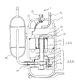
図1は、本発明の実施の形態1に係る圧縮機の縦断面図(回転軸の軸心方向に切断した断面図)である。圧縮機1は、密閉容器4内に、圧縮機構200と誘導電動機である電動機100と図示しない冷凍機油とを収納している。また、密閉容器4の上部には、圧縮機構200で圧縮された冷媒を外部に導く(吐出する)ための吐出管70も設けられている。なお、冷凍機油は、主に圧縮機構200の摺動部を潤滑するものであり、密閉容器4内の底部に貯留されている。
1 is a vertical cross-sectional view (a cross-sectional view cut in the axial direction of a rotating shaft) of a compressor according to
電動機100は、固定子12と回転子11とを備えている。固定子12は、略円筒形状に形成されており、外周部が密閉容器4に例えば焼き嵌め等により固定されている。この固定子12には巻線20(後述の主巻線20a及び補助巻線20b)が巻回されている。また、巻線20(つまり、主巻線20a及び補助巻線20b)は、リード線21を介して、密閉容器4に設けられたガラス端子15に接続されている。このガラス端子15は外部に設けられた電源(図示せず)に接続されている。つまり、固定子12の巻線20は、ガラス端子15及びリード線21を介して、外部電源から電力供給される構成となっている。
The electric motor 100 includes a
回転子11は、略円筒形状をしており、固定子12の内周面と所定の間隔を介して、固定子12の内周部に配置されている。本実施の形態1に係る回転子11は、後述のように、回転子鉄心11a及びかご形導体(エンドリング32、後述のアルミバー30)で構成されたかご形回転子である。この回転子11には回転軸3が固定されており、電動機100と圧縮機構200とは、回転軸3を介して接続された構成となっている。つまり、電動機100が回転することにより、圧縮機構200には、回転軸3を介して回転動力が伝達されることとなる。ここで、一般的に、密閉型圧縮機の性能を確保するためには、電動機に一定の冷媒の流路が必要である。このため、本実施の形態1に係る電動機100には、回転子11に、圧縮機構200から吐出された高圧のガス冷媒を電動機100の上方へ導く(冷媒の流路となる)ガス流路2が回転軸方向に貫通形成されている。
The
なお、電動機100の詳細構成については、後述する。 The detailed configuration of the electric motor 100 will be described later.
圧縮機構200は、シリンダ5、上軸受6(軸受の一例)、下軸受7(軸受の一例)、ローリングピストン9、吐出マフラ8、及びベーン(図示せず)等で構成される。
The
内部に圧縮室が形成されるシリンダ5は、外周が平面視略円形で、内部に平面視略円形の空間であるシリンダ室を備える。シリンダ室は、軸方向両端が開口している。シリンダ5は、側面視で所定の軸方向の高さを持つ。シリンダ5は、平面視略円形の空間であるシリンダ室に連通し、半径方向に延びる平行なベーン溝(図示せず)が軸方向に貫通して設けられる。また、ベーン溝背面(外側)に、ベーン溝に連通する平面視略円形の空間である背圧室(図示せず)が設けられる。 The cylinder 5 in which the compression chamber is formed has a cylinder chamber whose outer periphery has a substantially circular shape in plan view and is a substantially circular space in plan view. The cylinder chamber is open at both axial ends. The cylinder 5 has a predetermined axial height in a side view. The cylinder 5 communicates with a cylinder chamber, which is a substantially circular space in plan view, and is provided with parallel vane grooves (not shown) extending in the radial direction extending in the axial direction. In addition, a back pressure chamber (not shown) that is a substantially circular space in plan view communicating with the vane groove is provided on the back surface (outside) of the vane groove.
シリンダ5には、冷凍サイクル回路からの吸入ガスが通る吸入ポート(図示せず)が、シリンダ5の外周面からシリンダ室に貫通している。シリンダ5には、平面視略円形の空間であるシリンダ室を形成する円の縁部付近(電動機100側の端面)を切り欠いた吐出ポート(図示せず)が設けられる。 A suction port (not shown) through which suction gas from the refrigeration cycle circuit passes through the cylinder 5 passes through the cylinder chamber from the outer peripheral surface of the cylinder 5. The cylinder 5 is provided with a discharge port (not shown) in which the vicinity of the edge (end surface on the side of the electric motor 100) forming a cylinder chamber that is a substantially circular space in plan view is cut out.
ローリングピストン9は、シリンダ室内を偏心回転するものである。ローリングピストン9は、リング状に形成されており、ローリングピストン9の内周が回転軸3の偏心軸部3aに摺動自在に設けられている。
The rolling piston 9 rotates eccentrically in the cylinder chamber. The rolling piston 9 is formed in a ring shape, and the inner periphery of the rolling piston 9 is slidably provided on the
ベーンは、シリンダ5のベーン溝内に収納され、背圧室に設けられたベーンスプリング(図示せず)により、常にローリングピストン9に押し付けられている。なお、本実施の形態1に係る圧縮機1は密閉容器4内が高圧となるので、運転を開始するとベーンの背面(背圧室側)に密閉容器4内の高圧とシリンダ室の圧力との差圧による力が作用する。このため、ベーンスプリングは、主に圧縮機1の起動時(密閉容器4内とシリンダ室の圧力に差がない状態)に、ベーンをローリングピストン9に押し付ける目的で使用される。ベーンの形状は、平たい(周方向の厚さが、径方向及び軸方向の長さよりも小さい)略直方体である。
The vane is housed in the vane groove of the cylinder 5 and is always pressed against the rolling piston 9 by a vane spring (not shown) provided in the back pressure chamber. Since the
上軸受6は、回転軸3の主軸部(偏心軸部より上の部分)に摺動自在に嵌合するとともに、シリンダ5のシリンダ室(ベーン溝も含む)の一方の端面(電動機100側)を閉塞する。下軸受7は、回転軸3の副軸部(偏心軸部より下の部分)に摺動自在に嵌合するとともに、シリンダ5のシリンダ室(ベーン溝も含む)の他方の端面(冷凍機油側)を閉塞する。上軸受6及び下軸受7は、側面視略T字状に形成されている。
The upper bearing 6 is slidably fitted to the main shaft portion (a portion above the eccentric shaft portion) of the
また、上軸受6には、その外側(電動機100側)に吐出マフラ8が取り付けられている。上軸受6の吐出弁から吐出される高温・高圧の吐出ガスは、一端吐出マフラ8に入り、その後吐出マフラ8の吐出穴(図示せず)から密閉容器4内に放出される。
In addition, a
密閉容器4の横には、冷凍サイクル回路からの低圧の冷媒ガスを吸入し、液冷媒が戻る場合に液冷媒が直接シリンダ5のシリンダ室に吸入されるのを抑制する吸入マフラ80が設けられている。吸入マフラ80は、シリンダ5の吸入ポートに吸入管22を介して接続されている。吸入マフラ80は、例えば溶接等により密閉容器4の側面に固定される。
A
(電動機100の詳細構成)
続いて、本実施の形態1に係る電動機100の詳細について説明する。なお、以下では、まず図2を用いて固定子12の詳細を説明した後、図3及び図4を用いて回転子11の詳細について説明する。
(Detailed configuration of electric motor 100)
Next, details of the electric motor 100 according to the first embodiment will be described. In the following, the details of the
図2は、本発明の実施の形態1に係る電動機の横断面図(回転軸の軸心方向と直交する仮想平面で切断した断面図)である。
固定子12は、固定子鉄心12a、及び巻線20(主巻線20a及び補助巻線20b)で構成されている。固定子鉄心12aは、板厚が0.1mm〜1mmの電磁鋼板を所定の形状(例えばドーナツ形状)に打ち抜き、軸方向に積層し、カシメや溶接等により固定して製作される。これにより、固定子鉄心12aは、略円筒形状に形成される。なお、本実施の形態1では、固定子鉄心12aと密閉容器4との間に流路23を形成するため、固定子鉄心12aの外周面には、外周面を略平面状に切り欠いた切欠き12cを4ヶ所に形成している。4ヶ所の切欠き12cは、隣り合うもの同士が略直角に配置される。但し、これは一例であり、切欠き12cの数、形状及び配置は任意でよい。なお、流路23は、ガス流路2によって電動機100の上方へ導かれたガス冷媒から図示しない油分離器で分離された冷凍機油を密閉容器4の底部に戻す油戻し通路として機能する。
FIG. 2 is a cross-sectional view of the electric motor according to
The
この固定子鉄心12aには、内周縁に沿って、内周縁に開口した固定子スロット12bが形成されている。これら固定子スロット12bは、周方向にほぼ等間隔に配置され、半径方向に延在している。固定子スロット12bは内周縁に開口しており、この開口部をスロットオープニングと言う。このスロットオープニングから巻線20(主巻線20a及び補助巻線20b)が挿入される。
The
本実施の形態1に係る電動機100は、2極の単相誘導電動機である。このため、固定子12は、固定子スロット12bに挿入される(巻回される)主巻線20a及び補助巻線20bを備える。つまり、本実施の形態1に係る電動機100は、主巻線20a及び補助巻線20bで、巻線20を構成している。なお、固定子スロット12bには巻線20と固定子鉄心12aとの間の絶縁を確保するために絶縁材(例えば、スロットセル、ウェッジ等)が挿入されるが、ここでは省略する。また、この例では固定子スロット12bの数が24であるが、これは一例であり、固定子スロット12bの数は24に限定されるものではない。
Electric motor 100 according to the first embodiment is a two-pole single-phase induction motor. Therefore, the
主巻線20aは、同心巻方式の巻線である。図2の例では、固定子スロット12b内の内周側(回転子11に近い方)に、主巻線20aが配置されている。本実施の形態1では、同心巻方式の主巻線20aは、大きさ(特に周方向の長さ)が異なる5個のコイルで構成される。そして、これら5個のコイルは、縦断面視において各コイルの中心が同じ位置となるように固定子スロット12bに挿入される。そのため、同心巻方式と呼ばれる。なお本実施の形態1では主巻線20aが5個のコイルのものを示したが、これは一例であって、その数は問わない。
The main winding 20a is a concentric winding. In the example of FIG. 2, the main winding 20a is arranged on the inner peripheral side (the side closer to the rotor 11) in the
主巻線20aの5個のコイルを径の大きい方から順にM1、M2、M3、M4、M5とすると、各コイルの巻数は、主巻線20aの磁束の分布が略正弦波になるように選ばれる。主巻線20aに電流が流れた場合に発生する主巻線磁束が正弦波になるようにするためである。 Assuming that the five coils of the main winding 20a are M1, M2, M3, M4, and M5 in order from the largest, the number of turns of each coil is such that the distribution of magnetic flux in the main winding 20a becomes a substantially sine wave. To be elected. This is because the main winding magnetic flux generated when a current flows through the main winding 20a becomes a sine wave.
主巻線20aは、固定子スロット12b内の内周側、外周側のどちらに配置してもよい。主巻線20aを固定子スロット12b内の内周側に配置すると、固定子スロット12b内の外周側に配置する場合に比べて、巻線周長が短くなる。また、主巻線20aを固定子スロット12b内の内周側に配置すると、固定子スロット12b内の外周側に配置する場合に比べて、漏れ磁束が少なくなる。よって、主巻線20aを固定子スロット12b内の内周側に配置すると、固定子スロット12b内の外周側に配置する場合に比べて主巻線20aのインピーダンス(抵抗値、漏れリアクタンス)が小さくなる。そのため、単相誘導電動機の特性が良くなる。
The main winding 20a may be arranged on either the inner peripheral side or the outer peripheral side in the
主巻線20aに電流を流すことで、主巻線磁束が生成される。この主巻線磁束の向きは、図2の上下方向である。前述したように、この主巻線磁束の波形ができるだけ正弦波になるように、主巻線20aの5個のコイル(M1、M2、M3、M4、M5)の巻数が選ばれる。主巻線20aに流れる電流は交流であるから、主巻線磁束も流れる電流に従って大きさと位相を変える。 A main winding magnetic flux is generated by passing a current through the main winding 20a. The direction of the main winding magnetic flux is the vertical direction of FIG. As described above, the number of turns of the five coils (M1, M2, M3, M4, M5) of the main winding 20a is selected so that the waveform of the main winding magnetic flux is as sine as possible. Since the current flowing through the main winding 20a is alternating current, the magnitude and phase change according to the current flowing through the main winding magnetic flux.
また、固定子スロット12bには、主巻線20aと同様の同心巻方式の補助巻線20bが挿入される。詳しくは、本実施の形態1では、補助巻線20bは、大きさ(特に周方向の長さ)が異なる3個のコイルで構成される。そして、これら3個のコイルは、縦断面視において各コイルの中心が同じ位置となるように固定子スロット12bに挿入される。また、補助巻線20bの3個のコイルを大きい方から順にA1、A2、A3とすると、各コイルの巻数は、補助巻線磁束の分布が略正弦波になるように選ばれる。補助巻線20bに電流が流れた場合に発生する補助巻線磁束が正弦波になるようにするためである。
Further, a concentric winding type auxiliary winding 20b similar to the main winding 20a is inserted into the
図2では、補助巻線20bは、固定子スロット12b内の外側に配置されている。補助巻線20bに電流を流すことで補助巻線磁束が生成される。この補助巻線磁束の向きは、主巻線磁束の向きに直交する(図2の左右方向)。補助巻線20bに流れる電流は交流であるから、補助巻線磁束も電流に従って大きさと位相を変える。
In FIG. 2, the auxiliary winding 20b is disposed outside the
一般的には主巻線磁束と補助巻線磁束のなす角度が電気角で90度(ここでは極数が2極であるため、機械角も90度である)になるように、主巻線20aと補助巻線20bとが固定子スロット12bに挿入される。
In general, the main winding magnetic flux and the auxiliary winding magnetic flux have an electrical angle of 90 degrees (here, the number of poles is two, so the mechanical angle is also 90 degrees). 20a and the auxiliary winding 20b are inserted into the
補助巻線20bと直列に運転コンデンサを接続したものに主巻線20aを並列に接続させる。その両端を単相交流電源へ接続する。運転コンデンサを補助巻線20bに直列に接続することにより、補助巻線20bに流れる電流の位相を主巻線20aに流れる電流の位相より約90度進めることができる。 The main winding 20a is connected in parallel to the auxiliary winding 20b connected in series with the operating capacitor. Connect both ends to a single-phase AC power supply. By connecting the operating capacitor in series with the auxiliary winding 20b, the phase of the current flowing through the auxiliary winding 20b can be advanced by about 90 degrees from the phase of the current flowing through the main winding 20a.
主巻線20aと補助巻線20bの固定子鉄心12aにおける位置を電気角で90度ずらし、且つ主巻線20aと補助巻線20bの電流の位相を約90度異なるようにすることにより、2極の回転磁界が発生する。
The positions of the main winding 20a and the auxiliary winding 20b in the
図3は、本発明の実施の形態1に係る電動機の回転子の横断面図(回転軸の軸心方向と直交する仮想平面で切断した断面図)である。また、図4は、この回転子の斜視図である。なお、図4は、固定子鉄心12aを透過して示している。
回転子11は、回転子鉄心11aとかご形導体を備える。かご形導体は、アルミバー30及びエンドリング32で構成される。一般的にアルミバー30とエンドリング32はダイキャストにより同時にアルミニウムを鋳込むことで製作される。
FIG. 3 is a cross-sectional view of the rotor of the electric motor according to
The
回転子鉄心11aは、固定子鉄心12aと同様に板厚が0.1〜1mmの電磁鋼板を所定の形状(例えばドーナツ形状)に打ち抜き、軸方向に積層して製作される。本実施の形態1では、図3に符号「14」で示す位置にカシメを施すことにより、各電磁鋼板を固定している。なお、一般的には、回転子鉄心11aは、固定子鉄心12aと同一の材料から打ち抜くことが多い。但し、回転子鉄心11aと固定子鉄心12aの材料を変えても構わない。
The rotor core 11a is manufactured by punching electromagnetic steel sheets having a thickness of 0.1 to 1 mm into a predetermined shape (for example, donut shape) and laminating them in the axial direction in the same manner as the
このように形成された回転子鉄心11aは、中心付近に断面が円形の軸孔を備える。この軸孔には、回転軸3が焼き嵌め等により固定される。また、回転子鉄心には、周方向にほぼ等間隔に配置された回転子スロット13が形成されている。この回転子スロット13にアルミニウムを鋳込むことにより、かご形導体のアルミバー30が形成される。
The thus formed rotor core 11a includes a shaft hole having a circular cross section near the center. The
なお、上述した電動機100は、固定子鉄心12aのスロット数が24、回転子鉄心11aのスロット数が30の組合せである。但し、これは一例であり、固定子鉄心のスロット数が24、回転子スロット13の数が30に限定されるものではない。
The above-described electric motor 100 is a combination in which the number of slots of the
(ワニスの含浸工程)
続いて、固定子12の固定子スロット12bに巻回された(挿入された)巻線20へのワニス含浸工程について説明する。固定子スロット12bに巻回された巻線20には、巻線の表面を絶縁する目的、巻線をゴミ等から保護する目的、巻回時に傷ついた巻線の表面をコーティングする目的等により、ワニスが含浸される。本実施の形態1では、例えばエポキシ樹脂を主剤とするワニスを含浸する。
(Varnish impregnation process)
Next, the varnish impregnation step for the winding 20 wound (inserted) in the
ここで、巻線20へのワニスの含浸量が多くなるほど、つまり巻線20の単位面積あたりのワニス付着量を増加させるほど、巻線20の熱伝導率を大きくでき、巻線20の冷却性能を向上させることができる。これは、巻線20へのワニスの含浸量が多くなるほど、巻線20に付着したワニス内に気泡等が少なくなるためである。また、巻線20へのワニスの含浸量が多くなるほど、巻線の絶縁性能を向上できる為、漏洩電流を低減できる。つまり、巻線20へのワニスの含浸量を向上させることにより、冷媒吐出温度が高くなるR22冷媒を扱う圧縮機を小型化することができる。また、R22冷媒よりも吐出温度がさらに高いR32冷媒を扱うことができる圧縮機を得ることができる。 Here, as the amount of varnish impregnated into the winding 20 increases, that is, as the amount of varnish attached per unit area of the winding 20 increases, the thermal conductivity of the winding 20 can be increased, and the cooling performance of the winding 20 can be increased. Can be improved. This is because, as the amount of varnish impregnated into the winding 20 increases, bubbles and the like in the varnish adhering to the winding 20 decrease. Moreover, since the insulation performance of a coil | winding can be improved, so that the amount of varnish impregnations to the coil | winding 20 increases, a leakage current can be reduced. That is, by improving the amount of varnish impregnated in the winding 20, it is possible to reduce the size of the compressor that handles the R22 refrigerant that increases the refrigerant discharge temperature. Moreover, the compressor which can handle R32 refrigerant | coolant whose discharge temperature is still higher than R22 refrigerant | coolant can be obtained.
しかしながら、大気中で行う従来のワニス含浸方法で巻線20へワニスを含浸させた場合、ワニスの含浸量が不足してしまうため、圧縮機1でR22冷媒を扱おうとすると、巻線20の温度が上昇してしまう。このため、巻線20の温度をIEC規格を満たす温度まで低下させようとすると、圧縮機1が大型化してしまう。また、大気中で行う従来のワニス含浸方法で巻線20へワニスを含浸させた場合、圧縮機1でR22冷媒よりも吐出温度がさらに高いR32冷媒を扱おうとすると、圧縮機1を大型化しても巻線20の温度をIEC規格内に収めることができず、圧縮機1でR32冷媒を扱うことができない。
However, when the winding 20 is impregnated with the varnish by the conventional varnish impregnation method performed in the atmosphere, the amount of varnish impregnation is insufficient. Therefore, when the
そこで、本実施の形態1では、大気中において、次のように巻線20にワニスを含浸させることにより、巻線20へのワニスの含浸量を増加させている。 Therefore, in the first embodiment, the amount of varnish impregnated in the winding 20 is increased by impregnating the winding 20 with varnish in the atmosphere as follows.
図5は、本発明の実施の形態1に係る圧縮機における巻線へのワニス含浸方法を説明するための説明図である。
巻線20にワニスを含浸する際、まず、固定子スロット12bに巻線20が巻回された固定子12を、ハンガー50で保持する(図5(A)参照)。詳しくは、ハンガー50は、固定子12のリード線21側を保持するリード側受け部51と、固定子12におけるリード線21側の反対側を保持する反リード側受け部52と、を備えている。そして、これらリード側受け部51と反リード側受け部52とで固定子12を挟み込むことにより、固定子12をハンガー50で保持する。
FIG. 5 is an explanatory diagram for explaining a varnish impregnation method for windings in the compressor according to
When the winding 20 is impregnated with varnish, the
固定子12をハンガー50で保持した後、図5(B)に示すように、固定子12のリード線21側が下方となるように、固定子12を180度回転させる。そして、図5(C)に示すように、固定子12のリード線21側をワニス槽55内に貯留されたワニス56に浸漬させる。これにより、毛細管現象によって、ワニス56が巻線20の間にしみ込んでいく(ワニス供給工程)。このとき、本実施の形態1では、固定子12を振動させる(振動工程)。これにより、巻線20に付着するワニス56内から気泡を外部に放出させることができ、巻線20へのワニス56の含浸量を増加させることができる。
After the
図5(C)のワニス供給工程及び振動工程が終了した後、図5(D)に示すように、ワニス槽55内に貯留されたワニス56から固定子12を引き上げ、固定子12のリード線21側が上方となるように、固定子12を180度回転させる。これにより、巻線20に付着したワニス56の一部は、重力によって下方に流れつつ、下方の巻線20(反リード線側の巻線20)の間にしみ込んでいく。このとき、本実施の形態1では、固定子12を振動させる(振動工程)。これにより、図5(D)の工程において巻線20に付着するワニス56内からも気泡を外部に放出させることができ、巻線20へのワニス56の含浸量を増加させることができる。
After the varnish supply process and the vibration process in FIG. 5C are completed, the
図5(D)の工程の後、図5(E)に示すように、固定子12の反リード線21側をワニス槽55内に貯留されたワニス56に浸漬させる。これにより、毛細管現象によって、ワニス56が、上記の工程中にワニス56が供給されていなかった範囲の巻線20の間にもしみ込んでいく(ワニス供給工程)。このとき、本実施の形態1では、固定子12を振動させる(振動工程)。これにより、図5(E)の工程において巻線20に付着するワニス56内からも気泡を外部に放出させることができ、巻線20へのワニス56の含浸量を増加させることができる。
After the step of FIG. 5D, the side opposite to the
図5(E)のワニス供給工程及び振動工程が終了した後、図5(F)に示すように、ワニス槽55内に貯留されたワニス56から固定子12を引き上げ、固定子12の反リード線21側が上方となるように、固定子12を180度回転させる。これにより、巻線20に付着したワニス56の一部は、重力によって下方に流れつつ、下方の巻線20(反リード線側の巻線20)の間にしみ込んでいく。このとき、本実施の形態1では、固定子12を振動させる(振動工程)。これにより、図5(F)の工程において巻線20に付着するワニス56内からも気泡を外部に放出させることができ、巻線20へのワニス56の含浸量を増加させることができる。
After the varnish supply process and the vibration process in FIG. 5E are finished, the
なお、本実施の形態1では、ワニス供給工程中及びワニス供給工程後の双方において固定子12を振動させたが、どちらか一方において固定子12を振動させてもよい。但し、ワニス供給工程中に固定子12を振動させた方が、ワニス中から気泡を放出させる効果が大きい。このため、どちらか一方において固定子12を振動させる場合、ワニス供給工程中に固定子12を振動させる方が好ましい。
In the first embodiment, the
また、本実施の形態1では、固定子12のリード線21側をワニス56に浸漬させてワニス56を供給するワニス供給工程と、固定子12の反リード線21側をワニス56に浸漬させてワニス56を供給するワニス供給工程と、の双方を行っている。しかしながら、これに限らず、どちらか一方のワニス供給工程(より詳しくは、この工程の後に固定子12を反転させてワニス56を落下させる工程も含む)により十分にワニスを供給できる場合には、どちらか一方のワニス供給工程(例えば、固定子12の反リード線21側をワニス56に浸漬させてワニス56を供給するワニス供給工程)のみ行ってもよい。
Moreover, in this
また、本実施の形態1では、固定子12をワニス槽55内に貯留されたワニス56に浸漬させることにより、巻線20にワニス56を供給した。しかしながら、これに限らず、巻線の上方からワニス56を滴下して、巻線20にワニス56を供給しても勿論よい。
In the first embodiment, the
また、本実施の形態1では、ワニス含浸工程中のみ固定子12を振動させたが、ワニス含浸工程後も、ワニス56が乾燥するまで固定子12を振動させてもよい。これにより、ワニス含浸工程後においてもワニス56内から気泡を放出させることができ、巻線20へのワニス56の含浸密度(巻線20の単位面積あたりのワニス付着量)をさらに増加させることができる。
In the first embodiment, the
以上、本実施の形態1のように構成された圧縮機1においては、従来の大気中でのワニス含浸方法で製造された圧縮機に比べ、巻線20へのワニス56の含浸密度(巻線20の単位体積当りのワニス付着量)を増加させることができ、巻線20の熱伝導率を大きくできる。つまり、本実施の形態1に係る圧縮機1は、従来の大気中でのワニス含浸方法で製造された圧縮機に比べ、巻線20の冷却性能を向上でき、巻線20の温度を低下できる。また、本実施の形態1に係る圧縮機1は、従来の大気中でのワニス含浸方法で製造された圧縮機に比べ、巻線20の絶縁性能を向上できる為、漏洩電流を低減できる。このため、本実施の形態1に係る圧縮機1は、吐出温度が高いR22冷媒を用いる冷凍サイクル装置に使用される場合であっても、圧縮機1を小型化することができる。さらに、本実施の形態1に係る圧縮機1は、R22冷媒よりもさらに吐出温度が高いR32冷媒を用いる冷凍サイクル装置にも使用することができる。
As described above, in the
また、本実施の形態1に係る圧縮機1は、大気中でワニス含浸処理を行えるため、当該圧縮機1の製造に際し、真空中でワニス含浸処理を行う際に用いる真空槽等の設備や、真空槽の真空引きといった工程を必要としない。このため、本実施の形態1に係る圧縮機1は、圧縮機1の生産効率の低下や生産設備費の増加を抑制することもできる。
In addition, since the
なお、本発明は巻線20へのワニス56の含浸処理に特徴を有するものである。このため、密閉容器4内における電動機100及び圧縮機構200の配置関係(どちらの構成が密閉容器の上方に配置されるのか、双方の構成が横方向に配置されるのか等)、圧縮機構の種類(レシプロ式やスクロール式等、ロータリー式以外の圧縮機構であるか否か)、電動機100の種類(誘導電動機であるか否か)、巻線20の巻き方等は、本発明を限定するものではない。
The present invention is characterized by the impregnation treatment of the
実施の形態2.
実施の形態1では、ワニスの含浸工程中に固定子12を振動させることにより、巻線20へのワニスの含浸量を増加させた。これに限らず、例えば次のようなワニス含浸工程によって巻線20にワニスを含浸させても、巻線20へのワニスの含浸量を増加させることができる。なお、本実施の形態2で特に記述しない項目については実施の形態1と同様とし、同一の機能や構成については同一の符号を用いて述べることとする。
In the first embodiment, the amount of varnish impregnation into the winding 20 is increased by vibrating the
本実施の形態2に係るワニス含浸工程は、基本的に実施の形態1で示したワニス含浸工程と同様である。本実施の形態2に係るワニス含浸工程が実施の形態1で示したワニス含浸工程と異なる点は、
(1)ワニス含浸工程中に、固定子12を振動させない点、
(2)粘度の異なる2種類のワニスを用いる点、
である。
The varnish impregnation step according to the second embodiment is basically the same as the varnish impregnation step shown in the first embodiment. The difference between the varnish impregnation step according to the second embodiment and the varnish impregnation step shown in the first embodiment is that
(1) The point that the
(2) Two types of varnishes having different viscosities are used,
It is.
詳しくは、本実施の形態2に係るワニス含浸工程では、まず、粘度の低い方のワニスを用いて、例えば図5で示したような方法(但し、固定子12は振動していない)で巻線20にワニス56を含浸させる(第1のワニス含浸工程)。粘度の低いワニスは、巻線20の間にしみ込みやすいため、固定子スロット12bの奥側(固定子12の外周側)に配置された巻線20の間や、巻線20が密集した箇所にまで良好にしみ込むことができる。
Specifically, in the varnish impregnation step according to the second embodiment, first, using a varnish having a lower viscosity, for example, by a method as shown in FIG. 5 (however, the
一方、粘度の低いワニスは、重力によって落下しやすい(つまり、巻線20の間に留まりづらい)。このため、特に固定子スロット12bの手前側(固定子12の内周側)や、巻線20間の隙間が大きい箇所では、巻線20に付着する量が減少してしまう。そこで、本実施の形態2では、粘度の高い方のワニスを用いて、例えば図5で示したような方法(但し、固定子12は振動していない)で巻線20にワニス56を含浸させる(第2のワニス含浸工程)。粘度の高いワニスで再度のワニス含浸処理を行うことにより、粘度の低いワニスでは含浸量が不足していた箇所に粘度の高いワニスを含浸させることができる。このため、最終的には、巻線20へのワニスの含浸量を、従来の大気中でのワニス含浸方法よりも増加させることができる。
On the other hand, a varnish with a low viscosity tends to fall by gravity (that is, it is difficult to stay between the windings 20). For this reason, the amount adhering to the winding 20 is reduced particularly at the front side of the
なお、本実施の形態2では、粘度の低いワニスとしては例えば、エポキシポリエステル及びスチレン等の成分を有し、25℃時の粘度が180mPa・s〜260mPa・sとなるワニスを用いている。また、粘度の高いワニスとしては例えば、エポキシアクリレート及びメタクリレート等の成分を有し、25℃時の粘度が260mPa・s〜320mPa・sとなるワニスを用いている。 In the second embodiment, as the varnish having a low viscosity, for example, a varnish having components such as epoxy polyester and styrene and having a viscosity at 25 ° C. of 180 mPa · s to 260 mPa · s is used. Further, as the varnish having a high viscosity, for example, a varnish having components such as epoxy acrylate and methacrylate and having a viscosity at 25 ° C. of 260 mPa · s to 320 mPa · s is used.
以上、本実施の形態2のように構成された圧縮機1においては、実施の形態1と同様に、従来の大気中でのワニス含浸方法で製造された圧縮機に比べ、巻線20へのワニスの含浸量(巻線20の単位体積当りのワニス付着量)を増加させることができ、巻線20の熱伝導率を大きくできる。つまり、本実施の形態2に係る圧縮機1も、従来の大気中でのワニス含浸方法で製造された圧縮機に比べ、巻線20の冷却性能を向上でき、巻線20の温度を低下できる。また、本実施の形態2に係る圧縮機1も、従来の大気中でのワニス含浸方法で製造された圧縮機に比べ、巻線20の絶縁性能を向上できる為、漏洩電流を低減できる。このため、本実施の形態2に係る圧縮機1も、吐出温度が高いR22冷媒を用いる冷凍サイクル装置に使用される場合であっても、圧縮機1を小型化することができる。また、本実施の形態2に係る圧縮機1も、R22冷媒よりもさらに吐出温度が高いR32冷媒を用いる冷凍サイクル装置に使用することができる。
As described above, in the
なお、本実施の形態2で示した第1のワニス含浸工程及び第2のワニス含浸工程において、実施の形態1で示した固定子12の振動工程を追加しても勿論よい。巻線20へのワニスの含浸量をより増加させることができる。
In addition, in the 1st varnish impregnation process and the 2nd varnish impregnation process shown in this
実施の形態3.
実施の形態2では、組成の異なるワニスを用いることにより、第1のワニス含浸工程で供給するワニスの粘度と第2のワニス含浸工程で供給するワニスの粘度とを異ならせた。これに限らず、同一組成のワニスを用い、ワニスの温度を異ならせることにより、ワニスの粘度を異ならせてもよい。つまり、第1のワニス含浸工程では、巻線20に供給するワニスの温度を、第2のワニス含浸工程時に供給するワニスの温度よりも高くすればよい。これにより、同一組成のワニスを用いても、第1のワニス含浸工程で供給するワニスの粘度を第2のワニス含浸工程で供給するワニスの粘度よりも低くすることができる。
In
以上、本実施の形態3で示したようなワニス含浸工程で巻線20にワニスを含浸しても、従来の大気中でのワニス含浸方法で製造された圧縮機に比べ、巻線20へのワニスの含浸量(巻線20の単位体積当りのワニス付着量)を増加させることができ、実施の形態2と同様の効果を得ることができる。 As described above, even if the winding 20 is impregnated with the varnish in the varnish impregnation step as shown in the third embodiment, the winding 20 is not compared with the compressor manufactured by the conventional varnish impregnation method in the atmosphere. The amount of varnish impregnation (varnish adhesion amount per unit volume of winding 20) can be increased, and the same effect as in the second embodiment can be obtained.
実施の形態4.
実施の形態1〜実施の形態3では、大気中でワニス含浸工程を行っていた。これに限らず、実施の形態1〜実施の形態3のワニス含浸工程(少なくとも、ワニス中に気泡が混入するワニス供給工程)を真空中で行ってもよい。なお、本実施の形態4での真空とは、大気圧よりも低い圧力環境を示すものとする。
In the first to third embodiments, the varnish impregnation step is performed in the atmosphere. Not limited to this, the varnish impregnation step (at least the varnish supply step in which bubbles are mixed in the varnish) of
以上、本実施の形態4で示したワニス含浸工程は、ワニス中に気泡が混入しづらい環境下において巻線20にワニスを含浸できるため、巻線20へのワニスの含浸量をさらに増加できる。なお、本実施の形態4で示したワニス含浸工程は、真空槽等の設備や真空槽の真空引きといった工程を必要とするため、実施の形態1〜実施の形態3のワニス含浸工程と比べ、圧縮機1の生産効率の低下や生産設備費の増加を招く。しかしながら、本実施の形態4で示したワニス含浸工程は、巻線20へのワニスの含浸量を優先して圧縮機1を製造する際に、非常に有用なものである。
As described above, in the varnish impregnation step shown in the fourth embodiment, the winding 20 can be impregnated with the varnish in an environment in which air bubbles are not easily mixed into the varnish. In addition, since the varnish impregnation process shown in this
実施の形態5.
実施の形態1〜実施の形態4で示したワニス含浸処理工程を用いて製造された圧縮機1は、例えば次に示すような冷凍サイクル装置に用いられる。
Embodiment 5 FIG.
The
図6は、本発明の実施の形態5に係る冷凍サイクル装置の一例を示す構成図である。
この図6に示す冷凍サイクル装置300は、例えば、空気調和機に用いられるものである。図6に示すように、実施の形態1〜実施の形態4で示したワニス含浸処理工程を用いて製造された圧縮機1は、電源18に接続される。なお、圧縮機1の電動機100の補助巻線20bと電源18との間には、運転コンデンサ(図示せず)が接続される。電源18から電力が圧縮機1に供給され、圧縮機1が駆動する。この冷凍サイクル装置(空気調和機)は、圧縮機1、冷媒の流れる方向を切り替える四方弁301、室外熱交換器302、減圧装置303、及び室内熱交換器304等が冷媒配管で接続されて構成される。
FIG. 6 is a configuration diagram showing an example of a refrigeration cycle apparatus according to Embodiment 5 of the present invention.
The
冷凍サイクル装置300(空気調和機)は、例えば、冷房運転時、矢印のように冷媒が流れる。つまり、室外熱交換器302は凝縮器として機能し、室内熱交換器304は蒸発器として機能する。
In the refrigeration cycle apparatus 300 (air conditioner), for example, during the cooling operation, the refrigerant flows as indicated by an arrow. That is, the
図示はしないが、冷凍サイクル装置300(空気調和機)の暖房運転時は、冷媒は図4の矢印と反対方向の流れとなる。四方弁301によって、冷媒の流れる方向が切り替えられる。このとき、室外熱交換器302は蒸発器として機能し、室内熱交換器304は凝縮器として機能する。
Although not shown, during the heating operation of the refrigeration cycle apparatus 300 (air conditioner), the refrigerant flows in the direction opposite to the arrow in FIG. The direction in which the refrigerant flows is switched by the four-
以上、本実施の形態5のように構成された冷凍サイクル装置300においては、実施の形態1〜実施の形態4で示したワニス含浸処理工程を用いて製造された圧縮機1を用いているので、R22冷媒を使用する際、小型の圧縮機1を用いることができる。また、R32冷媒を用いた冷凍サイクル装置300を実用化することができる。
As described above, in the
なお、本実施の形態5では、空気調和機に用いられる冷凍サイクル装置300を例に説明したが、ヒートポンプ式貯湯装置や冷凍装置等に用いられる冷凍サイクル装置に圧縮機1を用いても勿論よい。
In the fifth embodiment, the
1 圧縮機、2 ガス流路、3 回転軸、3a 偏心軸部、4 密閉容器、5 シリンダ、6 上軸受、7 下軸受、8 吐出マフラ、9 ローリングピストン、11 回転子、11a 回転子鉄心、12 固定子、12a 固定子鉄心、12b 固定子スロット、12c 切欠き、13 回転子スロット、14 カシメ、15 ガラス端子、18 電源、20 巻線、20a 主巻線、20b 補助巻線、21 リード線、22 吸入管、23 流路、30 アルミバー、32 エンドリング、50 ハンガー、51 リード側受け部、52 反リード側受け部、55 ワニス槽、56 ワニス、70 吐出管、80 吸入マフラ、100 電動機、200 圧縮機構、300 冷凍サイクル装置、301 四方弁、302 室外熱交換器、303 減圧装置、304 室内熱交換器。
DESCRIPTION OF
Claims (5)
該固定子の内周面に該固定子と所定の間隔を介して配置された回転子と、
を備え、
前記巻線にワニスが含浸された電動機の製造方法であって、
前記巻線にワニスが含浸するワニス含浸工程として、
反リード線側の巻線とリード線側の巻線とが上下に配置された状態で、前記固定子の前記スロットに巻回された前記巻線の一部をワニス槽内に貯留された前記ワニスに浸漬させるワニス供給工程と、
該ワニス供給工程中に前記固定子を振動させる振動工程と、
前記ワニス槽内に貯留された前記ワニスから前記固定子を引き上げ、前記巻線における前記ワニスに浸漬されていた部分が上方となるように前記固定子を回転させて、前記固定子を振動させる振動工程と、
を有することを特徴とする電動機の製造方法。 A stator in which a slot is formed, and a winding wound around the slot;
A rotor disposed on the inner peripheral surface of the stator with a predetermined distance from the stator;
With
A method of manufacturing an electric motor in which the winding is impregnated with varnish,
As a varnish impregnation step in which the winding is impregnated with varnish,
In a state where the winding on the side opposite to the lead wire and the winding on the lead wire side are arranged vertically, a part of the winding wound around the slot of the stator is stored in the varnish tank. A varnish supplying step for immersing in the varnish;
A vibration step of vibrating the stator during the varnish supply step;
Vibration that pulls up the stator from the varnish stored in the varnish tank and rotates the stator so that the portion of the winding immersed in the varnish is on the upper side, thereby vibrating the stator Process,
A method for manufacturing an electric motor, comprising:
粘度が低い方の前記ワニスを用いて前記ワニス供給工程と前記振動工程とを行う第1のワニス含浸工程と、
粘度が高い方の前記ワニスを用いて前記ワニス供給工程と前記振動工程とを行う第2のワニス含浸工程と、
を有することを特徴とする請求項1に記載の電動機の製造方法。 Two varnishes with different viscosities are used as the varnish,
A first varnish impregnation step of performing the varnish supply step and the vibration step using the varnish having a lower viscosity;
A second varnish impregnation step of performing the varnish supply step and the vibration step using the varnish having a higher viscosity;
The method of manufacturing an electric motor according to claim 1 , comprising:
前記ワニスの温度を異ならせることにより、前記ワニスの粘度を変更することを特徴とする請求項2に記載の電動機の製造方法。 The varnishes having different viscosities are varnishes having the same composition,
The method for manufacturing an electric motor according to claim 2 , wherein the temperature of the varnish is varied to change the viscosity of the varnish.
少なくとも前記巻線へ前記ワニスを供給する工程は真空中で行われることを特徴とする請求項1〜請求項4のいずれか一項に記載の電動機の製造方法。 In the impregnation step of the varnish into the winding,
The method of manufacturing an electric motor according to claim 1 , wherein at least the step of supplying the varnish to the winding is performed in a vacuum.
Priority Applications (4)
| Application Number | Priority Date | Filing Date | Title |
|---|---|---|---|
| JP2012033915A JP5967971B2 (en) | 2012-02-20 | 2012-02-20 | Manufacturing method of electric motor |
| CZ2013-73A CZ309871B6 (en) | 2012-02-20 | 2013-02-04 | An electric motor, a compressor with an electric motor, a cooling cycle device with a compressor, and a method of manufacturing an electric motor |
| CN201310054023.6A CN103259379B (en) | 2012-02-20 | 2013-02-20 | Motor and manufacture method thereof, there is the compressor of this motor, there is the refrigerating circulatory device of this compressor |
| CN201320077960.9U CN203377754U (en) | 2012-02-20 | 2013-02-20 | Motor, compressor having the motor and refrigeration cycle apparatus having the compressor |
Applications Claiming Priority (1)
| Application Number | Priority Date | Filing Date | Title |
|---|---|---|---|
| JP2012033915A JP5967971B2 (en) | 2012-02-20 | 2012-02-20 | Manufacturing method of electric motor |
Publications (3)
| Publication Number | Publication Date |
|---|---|
| JP2013172518A JP2013172518A (en) | 2013-09-02 |
| JP2013172518A5 JP2013172518A5 (en) | 2014-07-24 |
| JP5967971B2 true JP5967971B2 (en) | 2016-08-10 |
Family
ID=48963134
Family Applications (1)
| Application Number | Title | Priority Date | Filing Date |
|---|---|---|---|
| JP2012033915A Expired - Fee Related JP5967971B2 (en) | 2012-02-20 | 2012-02-20 | Manufacturing method of electric motor |
Country Status (3)
| Country | Link |
|---|---|
| JP (1) | JP5967971B2 (en) |
| CN (2) | CN103259379B (en) |
| CZ (1) | CZ309871B6 (en) |
Cited By (2)
| Publication number | Priority date | Publication date | Assignee | Title |
|---|---|---|---|---|
| USD938095S1 (en) * | 2013-04-01 | 2021-12-07 | Pathy Medical, Llc | Lighting device |
| US11519569B2 (en) | 2013-04-01 | 2022-12-06 | Pathy Medical, Llc | Lighting device with cavity for removably attaching to a tool |
Families Citing this family (5)
| Publication number | Priority date | Publication date | Assignee | Title |
|---|---|---|---|---|
| JPWO2015136980A1 (en) * | 2014-03-14 | 2017-04-06 | 三菱電機株式会社 | Refrigeration cycle equipment |
| JP2015211603A (en) * | 2014-04-30 | 2015-11-24 | 三菱電機株式会社 | Motor, sealed type compressor, and refrigerating cycle device |
| CN105680644B (en) * | 2014-11-20 | 2019-01-29 | 上海海立电器有限公司 | Improve the method and compressor electric motor insulation system of compressor electric motor insulation performance |
| JP6689394B2 (en) | 2016-10-06 | 2020-04-28 | 三菱電機株式会社 | Electric motor and compressor equipped with the same |
| CN107359761B (en) * | 2017-08-28 | 2023-05-26 | 广东美芝制冷设备有限公司 | Single-phase induction motor and compressor |
Family Cites Families (13)
| Publication number | Priority date | Publication date | Assignee | Title |
|---|---|---|---|---|
| JPS5324502A (en) * | 1976-08-20 | 1978-03-07 | Hitachi Ltd | Insulation treating method of revolving mach ine |
| JPH01185152A (en) * | 1988-01-14 | 1989-07-24 | Mitsubishi Electric Corp | Varnish impregnation in coil |
| JP2978198B2 (en) * | 1990-03-30 | 1999-11-15 | 株式会社日立製作所 | Manufacturing method for electrical equipment windings |
| JPH05115160A (en) * | 1991-07-16 | 1993-05-07 | Toshiba Chem Corp | Insulating varnish impregnation of stator coil |
| JPH06327201A (en) * | 1993-05-17 | 1994-11-25 | Toshiba Corp | Varnish impregnation method for electronic appliance and device therefor |
| JPH06327203A (en) * | 1993-05-17 | 1994-11-25 | Toshiba Corp | Varnish impregnation method for electronic appliance |
| JPH07163102A (en) * | 1993-12-06 | 1995-06-23 | Toshiba Corp | Insulation processing for winding |
| JPH09285079A (en) * | 1996-04-15 | 1997-10-31 | Fanuc Ltd | Manufacturing method and manufacturing apparatus of stator of synchronous motor |
| JPH10304612A (en) * | 1997-04-24 | 1998-11-13 | Hitachi Ltd | Ac commutator motor |
| JP2005285933A (en) * | 2004-03-29 | 2005-10-13 | Kyocera Chemical Corp | Coil impregnation method of insulating varnish, and its coil |
| JP2006187059A (en) * | 2004-12-24 | 2006-07-13 | Kyocera Chemical Corp | Method and apparatus for impregnating insulation varnish |
| JP2009222032A (en) * | 2008-03-18 | 2009-10-01 | Daikin Ind Ltd | Refrigerating apparatus |
| JP2010068600A (en) * | 2008-09-09 | 2010-03-25 | Mitsubishi Electric Corp | Permanent magnet motor and hermetic compressor |
-
2012
- 2012-02-20 JP JP2012033915A patent/JP5967971B2/en not_active Expired - Fee Related
-
2013
- 2013-02-04 CZ CZ2013-73A patent/CZ309871B6/en unknown
- 2013-02-20 CN CN201310054023.6A patent/CN103259379B/en active Active
- 2013-02-20 CN CN201320077960.9U patent/CN203377754U/en not_active Expired - Fee Related
Cited By (3)
| Publication number | Priority date | Publication date | Assignee | Title |
|---|---|---|---|---|
| USD938095S1 (en) * | 2013-04-01 | 2021-12-07 | Pathy Medical, Llc | Lighting device |
| US11519569B2 (en) | 2013-04-01 | 2022-12-06 | Pathy Medical, Llc | Lighting device with cavity for removably attaching to a tool |
| USD991542S1 (en) * | 2013-04-01 | 2023-07-04 | Pathy Medical, Llc | Lighting device |
Also Published As
| Publication number | Publication date |
|---|---|
| JP2013172518A (en) | 2013-09-02 |
| CN103259379B (en) | 2016-04-27 |
| CZ201373A3 (en) | 2013-10-09 |
| CN103259379A (en) | 2013-08-21 |
| CZ309871B6 (en) | 2024-01-03 |
| CN203377754U (en) | 2014-01-01 |
Similar Documents
| Publication | Publication Date | Title |
|---|---|---|
| JP5967971B2 (en) | Manufacturing method of electric motor | |
| US20170045268A1 (en) | Electric motor, hermetic compressor, and refrigeration cycle apparatus | |
| JP5591099B2 (en) | Compressor and refrigeration cycle equipment | |
| US9214839B2 (en) | Three-phase dynamoelectric machines and stators with phase windings formed of different conductor material(s) | |
| JP6742402B2 (en) | Electric motor, compressor, and refrigeration cycle device | |
| JP4762301B2 (en) | Electric motor for compressor, compressor and refrigeration cycle apparatus | |
| CN105545746B (en) | Compressor Manufacturing device and Compressor Manufacturing method | |
| WO2009084245A1 (en) | Electric motor for compressor, compressor, and freezing cycle device | |
| CN109072917B (en) | Rotary compressor and refrigeration cycle device | |
| EP3468008B1 (en) | Ammonia-resistant electric motor for hermetic refrigeration compressor | |
| KR101843587B1 (en) | Polyphase dynamoelectric machines and stators with phase windings formed of different conductor material(s) | |
| EP1690006B1 (en) | Hermetic compressor | |
| CN102130553B (en) | Single-phase induction motor for compressor, compressor thereof and refrigeration circulation device | |
| JP2012139069A (en) | Sealed compressor | |
| JP5230574B2 (en) | Electric motor for compressor, compressor and refrigeration cycle apparatus | |
| JP6556342B2 (en) | Stator, motor, compressor and refrigeration cycle equipment | |
| WO2022264361A1 (en) | Hermetic compressor and refrigeration cycle apparatus | |
| JP2014195384A (en) | Motor for compressor, compressor, and refrigeration cycle device | |
| CN112955656B (en) | Compressor and refrigeration cycle device | |
| KR20090112322A (en) | Compressor | |
| JP5738213B2 (en) | Compressor and refrigeration cycle apparatus provided with the compressor | |
| WO2016181445A1 (en) | Compressor | |
| JP2013051881A (en) | Induction motor, compressor, and refrigeration cycle device |
Legal Events
| Date | Code | Title | Description |
|---|---|---|---|
| A521 | Request for written amendment filed |
Free format text: JAPANESE INTERMEDIATE CODE: A523 Effective date: 20140610 |
|
| A621 | Written request for application examination |
Free format text: JAPANESE INTERMEDIATE CODE: A621 Effective date: 20140610 |
|
| A977 | Report on retrieval |
Free format text: JAPANESE INTERMEDIATE CODE: A971007 Effective date: 20150326 |
|
| A131 | Notification of reasons for refusal |
Free format text: JAPANESE INTERMEDIATE CODE: A131 Effective date: 20150331 |
|
| A521 | Request for written amendment filed |
Free format text: JAPANESE INTERMEDIATE CODE: A523 Effective date: 20150527 |
|
| A131 | Notification of reasons for refusal |
Free format text: JAPANESE INTERMEDIATE CODE: A131 Effective date: 20151117 |
|
| A521 | Request for written amendment filed |
Free format text: JAPANESE INTERMEDIATE CODE: A523 Effective date: 20160112 |
|
| TRDD | Decision of grant or rejection written | ||
| A01 | Written decision to grant a patent or to grant a registration (utility model) |
Free format text: JAPANESE INTERMEDIATE CODE: A01 Effective date: 20160607 |
|
| A61 | First payment of annual fees (during grant procedure) |
Free format text: JAPANESE INTERMEDIATE CODE: A61 Effective date: 20160705 |
|
| R150 | Certificate of patent or registration of utility model |
Ref document number: 5967971 Country of ref document: JP Free format text: JAPANESE INTERMEDIATE CODE: R150 |
|
| R250 | Receipt of annual fees |
Free format text: JAPANESE INTERMEDIATE CODE: R250 |
|
| R250 | Receipt of annual fees |
Free format text: JAPANESE INTERMEDIATE CODE: R250 |
|
| R250 | Receipt of annual fees |
Free format text: JAPANESE INTERMEDIATE CODE: R250 |
|
| R250 | Receipt of annual fees |
Free format text: JAPANESE INTERMEDIATE CODE: R250 |
|
| LAPS | Cancellation because of no payment of annual fees |