JP5965434B2 - Image display system, lighting system, information processing apparatus, and control program - Google Patents
Image display system, lighting system, information processing apparatus, and control program Download PDFInfo
- Publication number
- JP5965434B2 JP5965434B2 JP2014124047A JP2014124047A JP5965434B2 JP 5965434 B2 JP5965434 B2 JP 5965434B2 JP 2014124047 A JP2014124047 A JP 2014124047A JP 2014124047 A JP2014124047 A JP 2014124047A JP 5965434 B2 JP5965434 B2 JP 5965434B2
- Authority
- JP
- Japan
- Prior art keywords
- light
- game
- image
- data
- lighting device
- Prior art date
- Legal status (The legal status is an assumption and is not a legal conclusion. Google has not performed a legal analysis and makes no representation as to the accuracy of the status listed.)
- Active
Links
Images


Description
本発明は、画像表示システム等に関し、より特定的には、表示画面に画像を表示させる
とともに、画像に加えてさらなる視覚効果をユーザに与える画像表示システム等に関する
。
The present invention relates to an image display system and the like, and more particularly to an image display system and the like that display an image on a display screen and give a user a further visual effect in addition to the image.
従来、テレビジョン受像器(以下、単に「テレビ」と記載する)にテレビ放送の画像や
ゲーム画像等を表示させる画像表示システムがある。例えば、特許文献1には、ユーザが
手に持ったコントローラを動かすことでゲーム操作を行い、ゲーム操作に応じて変化する
ゲーム画像をテレビに表示させるゲームシステムが開示されている。このゲームシステム
では、ゲーム装置本体の付属装置として、赤外光を発する装置(マーカ部)がテレビの周
辺に設置される。マーカ部は、ゲーム装置がコントローラの動きを算出するために用いら
れるものであり、ゲーム装置は、コントローラが有するカメラによる撮像画像におけるマ
ーカ部(赤外光)の位置に基づいてコントローラの動きを算出する。
2. Description of the Related Art Conventionally, there is an image display system that displays television broadcast images, game images, and the like on a television receiver (hereinafter simply referred to as “TV”). For example,
従来の画像表示システムは、テレビの画像やゲーム画像等をテレビの画面に表示するの
みであった。そのため、テレビの画面内に表示される画像でしかユーザに対して視覚的な
効果を与えることができず、画像の臨場感や迫力に限界があった。また、上記特許文献1
のゲームシステムのように、テレビ周辺に設置される付属装置は存在したものの、テレビ
と共にユーザに対して視覚的な効果を与える付属装置は存在しなかった。
Conventional image display systems only display television images, game images, and the like on the television screen. Therefore, a visual effect can be given to the user only with an image displayed on the screen of the television, and there is a limit to the presence and power of the image. In addition, the
As in the game system of FIG. 1, there are accessory devices installed around the television, but there is no accessory device that gives a visual effect to the user together with the television.
それ故、本発明の目的は、画面に表示される画像に加えてさらなる視覚的効果をユーザ
に与えることができる画像表示システム等(画像表示システム、照明システム、情報処理
装置、および制御プログラム)を提供することである。
Therefore, an object of the present invention is to provide an image display system or the like (an image display system, a lighting system, an information processing apparatus, and a control program) that can give a user a further visual effect in addition to an image displayed on a screen. Is to provide.
本発明は、上記の課題を解決するために、以下の(1)〜(9)の構成を採用した。 The present invention employs the following configurations (1) to (9) in order to solve the above problems.
(1)
本発明は、ネットワークを介してサーバと通信可能な情報処理装置と、情報処理装置から信号を受信可能な照明装置とを含む照明システムである。情報処理装置は、受信手段と、投光制御手段とを備える。受信手段は、テレビ放送の画像および/または音声に合わせて照明装置を発光させる指示を示す、チャンネル毎の指示データをサーバから受信する。投光制御手段は、受信された指示データに基づいて、照明装置の投光を制御する制御信号を照明装置へ出力する。照明装置は、制御信号に従って可視光を投光する。情報処理装置は、テレビ放送を受信して画像を画面に表示する放送受信装置に対して指示を行うことが可能である。情報処理装置は、ユーザによるチャンネルの入力に応じて、入力された1つのチャンネルを選局する指示を放送受信装置に対して行うとともに、入力された1つのチャンネルに対応する指示データを当該チャンネルの入力に応じてサーバに対して要求し、当該指示データをサーバから受信する。
(1)
The present invention is an illumination system including an information processing apparatus capable of communicating with a server via a network and an illumination apparatus capable of receiving a signal from the information processing apparatus. The information processing apparatus includes a receiving unit and a light projection control unit. The receiving means receives instruction data for each channel indicating an instruction to cause the lighting device to emit light in accordance with an image and / or sound of a television broadcast. The light projection control means outputs a control signal for controlling the light projection of the lighting device to the lighting device based on the received instruction data. The illumination device projects visible light according to the control signal. The information processing apparatus can instruct a broadcast receiving apparatus that receives a television broadcast and displays an image on a screen. In response to the input of the channel by the user, the information processing apparatus issues an instruction to select the one input channel to the broadcast receiving apparatus, and transmits instruction data corresponding to the input one channel to the channel. A request is made to the server in response to the input, and the instruction data is received from the server.
上記「情報処理装置」は、サーバと通信可能で、かつ、照明装置を制御可能な任意の情
報処理装置を含む概念である。すなわち、「情報処理装置」は、後述する実施形態ではゲ
ーム装置であるが、ゲーム処理を実行可能な装置に限らず、例えば、パーソナルコンピュ
ータであってもよい。
上記「照明装置」は、情報処理装置と通信可能であればよく、後述する実施形態におい
ては有線で接続されるが、電波および赤外線等によって無線で表示制御装置と通信を行う
ものであってもよい。
上記「指示データ」は、テレビ放送の画像および/または音声と照明装置の発光に何ら
かの関連性を持たせて発光させるものであればよい。例えば、番組で場面が切り替わった
ことに応じて発光状態が変化するように指示を行うものであってもよいし、番組で流れる
音楽に応じて発光状態が変化するように指示を行うものであってもよい。また、照明装置
の発光は、画像およびまたは音声に対して厳密に同期する必要はない。
上記「投光制御手段」の処理は、後述する実施形態においてはステップS5,S14の
処理に相当し、上記「制御信号」とは、後述する実施形態においては発光制御データであ
るが、照明装置を制御するための各種指示を示す信号(データ)であればどのような内容
であってもよい。
The “information processing apparatus” is a concept including an arbitrary information processing apparatus that can communicate with a server and can control a lighting device. That is, the “information processing apparatus” is a game apparatus in the embodiment described later, but is not limited to an apparatus capable of executing game processing, and may be a personal computer, for example.
The above “illumination device” is only required to be able to communicate with the information processing device, and in the embodiment described later, it is connected by wire, but even if it communicates with the display control device wirelessly by radio waves, infrared rays, or the like. Good.
The “instruction data” may be any data as long as the image and / or sound of the television broadcast and the light emission of the lighting device have a certain relationship. For example, an instruction may be given to change the lighting state in response to a scene change in a program, or an instruction may be provided to change the lighting state in accordance with music flowing in the program. May be. Further, the light emission of the lighting device does not need to be strictly synchronized with the image and / or sound.
The processing of the “light projection control means” corresponds to the processing of steps S5 and S14 in the embodiment described later, and the “control signal” is light emission control data in the embodiment described later. Any content may be used as long as it is a signal (data) indicating various instructions for controlling the control.
上記(1)の構成によれば、テレビ番組を視聴する際に照明装置をテレビの周囲に設置
することで、テレビ番組の画像に対して、照明装置の投光による照明効果を付加すること
ができる。したがって、テレビ番組の画像に加えてさらなる視覚的効果をユーザに与える
ことができ、テレビ番組の迫力や臨場感を向上させることができる。
According to the configuration of (1) above, when the television program is viewed, the illumination device is installed around the television, so that the illumination effect by the projection of the illumination device can be added to the image of the television program. it can. Therefore, a further visual effect can be given to the user in addition to the image of the television program, and the power and presence of the television program can be improved.
(2)
情報処理装置は、テレビ放送を受信して画像を画面に表示する放送受信装置に接続可能
であってもよい。また、情報処理装置は、ゲーム処理手段と、ゲーム表示制御手段とをさ
らに備えている。ゲーム処理手段は、所定のゲーム処理を実行する。ゲーム表示制御手段
は、ゲーム処理に応じたゲーム画像を放送受信装置の画面に表示させる。このとき、投光
制御手段は、放送受信装置の画面にゲーム画像が表示される場合、ゲーム処理に基づいて
照明装置の投光を制御する。
(2)
The information processing apparatus may be connectable to a broadcast receiving apparatus that receives a television broadcast and displays an image on a screen. The information processing apparatus further includes game processing means and game display control means. The game processing means executes a predetermined game process. The game display control means displays a game image corresponding to the game process on the screen of the broadcast receiving device. At this time, when a game image is displayed on the screen of the broadcast receiving device, the light projection control unit controls the light projection of the lighting device based on the game process.
上記「放送受信装置」は、後述する実施形態ではテレビ2であるが、テレビ放送を受信
する機能(チューナ)と画像を表示する機能(表示装置)とが別体で構成されていてもよ
い。
上記「ゲーム処理」は、後述する実施形態ではステップS3の処理であるが、ゲーム処
理の具体的な内容はどのようなものであってもよい。
上記「ゲーム表示制御手段」の処理は、後述する実施形態ではステップS4の処理であ
るが、任意のゲーム画像を表示する処理であれば具体的な表示内容はどのようなものであ
ってもよい。
In the embodiment described later, the “broadcast receiving device” is the
The above “game process” is the process of step S3 in the embodiment described later, but any specific content of the game process may be used.
The process of the “game display control unit” is the process of step S4 in the embodiment described later, but any specific display content may be used as long as it is a process of displaying an arbitrary game image. .
上記(2)の構成によれば、放送受信装置がゲーム画像を表示する場合には、当該ゲー
ム画像に応じた照明効果が照明装置によって行われる。したがって、照明システムは、テ
レビ番組だけでなくゲーム画像に対してもさらなる視覚的効果を付加することができ、ゲ
ームの迫力や臨場感を向上させることができる。
According to the configuration of (2) above, when the broadcast receiving apparatus displays a game image, a lighting effect corresponding to the game image is performed by the lighting apparatus. Therefore, the lighting system can add a further visual effect not only to the TV program but also to the game image, and can improve the power and realism of the game.
(3)
照明システムは、赤外光を発する赤外発光装置と、赤外光を検知可能な撮像手段を備え
る入力装置とをさらに含んでいてもよい。このとき、ゲーム処理手段は、撮像手段が撮像
した赤外光の位置に基づいてゲーム処理を実行する。
(3)
The illumination system may further include an infrared light emitting device that emits infrared light and an input device that includes an imaging unit capable of detecting infrared light. At this time, the game processing means executes game processing based on the position of the infrared light imaged by the imaging means.
上記「赤外発光装置」は、後述する実施形態における赤外LED(マーカ6Rおよび6
L)の他、赤外光を発する各種の発光装置を含む概念である。
上記「入力装置」は、後述する実施形態においてはコントローラ5であるが、コントロ
ーラ5のように操作ボタンや加速度センサ37を備えている必要はなく、撮像手段を少な
くとも備えていればよい。また、「撮像手段」は、後述する実施形態においてはCMOS
センサやあるいはCCDセンサのような固体撮像素子であるが、赤外光を検知することが
可能な撮像素子(撮像装置)であればよい。
The above “infrared light emitting device” is an infrared LED (
In addition to L), it is a concept including various light-emitting devices that emit infrared light.
The above-mentioned “input device” is the
Although it is a solid-state image sensor such as a sensor or a CCD sensor, any image sensor (imaging device) that can detect infrared light may be used.
上記(3)の構成によれば、撮像手段によって撮像された赤外光の位置を入力として所
定の情報処理が実行されるので、ユーザは、撮像手段を備える入力装置を動かす操作によ
ってゲームの入力を行うことができる。
According to the configuration of (3) above, since predetermined information processing is executed with the position of the infrared light imaged by the imaging means as an input, the user can input a game by operating the input device including the imaging means. It can be performed.
(4)
照明装置は、音声出力手段をさらに備えていてもよい。このとき、指示データは、テレ
ビ放送の画像および/または音声に合わせて音声出力手段に音を出力させる指示をさらに
示す。投光制御手段は、受信された指示データに基づいて音声出力装置の音出力をさらに
制御する。
(4)
The lighting device may further include an audio output unit. At this time, the instruction data further indicates an instruction for the sound output means to output sound in accordance with the image and / or sound of the television broadcast. The light projection control unit further controls the sound output of the sound output device based on the received instruction data.
上記「音声出力手段」とは、後述する実施形態におけるスピーカ112の他、音を出力
する機能を有する任意の装置を含む概念である。
The “sound output unit” is a concept including an arbitrary device having a function of outputting sound in addition to the
上記(4)の構成によれば、照明システムは、照明装置9を用いてユーザに視覚的効果
を与えることに加え、聴覚的効果をも与えることができる。
According to the configuration of (4) above, the lighting system can provide an auditory effect in addition to giving a visual effect to the user using the
(5)
照明装置は、テレビ放送の画像が表示される表示画面の後方に向けて可視光を出射する
ように設置されてもよい。
(5)
The lighting device may be installed so as to emit visible light toward the rear of a display screen on which an image of a television broadcast is displayed.
なお、上記「表示画面の後方に向けて可視光を出射する」とは、厳密な意味で「表示画
面に垂直な向きに出射する」ことのみを意味するのではなく、広く、「出射方向が、表示
画面に平行な向きよりも後側を向いている」ことを意味する。例えば、後述する実施形態
のように、表示画面の後方のやや上方に向けて出射する場合も、「表示画面の後方に向け
て可視光を出射する」場合に含まれる。
In addition, the above-mentioned “emitting visible light toward the rear of the display screen” does not mean, in a strict sense, “emitting in a direction perpendicular to the display screen”. , ”Is pointing to the rear side rather than the direction parallel to the display screen. For example, as in an embodiment to be described later, the case where the light is emitted slightly toward the rear of the display screen is also included in the case of “emitting visible light toward the rear of the display screen”.
上記(5)の構成によれば、表示画面の後方の壁面等に照明装置による光が投光される
。したがって、表示画面の前方に位置するユーザから見れば、表示画面の周りに光が投光
されているように見え(図15)、表示される画像に対して照明効果を効果的に付加する
ことができる。
According to the configuration of (5) above, light from the lighting device is projected onto a wall surface or the like behind the display screen. Therefore, from the viewpoint of a user located in front of the display screen, light appears to be projected around the display screen (FIG. 15), and an illumination effect is effectively added to the displayed image. Can do.
(6)
照明装置は、複数の発光素子と、集光レンズとを備えていてもよい。複数の発光素子は
、所定の方向に一列に配置され、互いに異なる色の光を発する。集光レンズは、複数の発
光素子からの可視光を透過する位置に配置され、所定の方向と垂直な方向にのみ光を集束
する。
(6)
The lighting device may include a plurality of light emitting elements and a condensing lens. The plurality of light emitting elements are arranged in a line in a predetermined direction and emit light of different colors. The condenser lens is disposed at a position that transmits visible light from the plurality of light emitting elements, and focuses the light only in a direction perpendicular to a predetermined direction.
上記「複数の発光素子」は、後述する実施形態では3つのLED75〜77の他、2以
上の任意の発光素子を含む概念である。また、「集光レンズ」は、後述する実施形態にお
ける平面状のフレネルレンズの他、シリンドリカルレンズ等の曲面を有するレンズであっ
てもよい。
In the embodiment described later, the “plurality of light emitting elements” is a concept including two or more arbitrary light emitting elements in addition to the three
上記(6)の構成によれば、各発光素子が配置される方向と集光レンズの集束方向とが
垂直になるので、各発光素子からの光は、配置方向に関しては集束されず、配置方向と垂
直な方向にのみ集束される。これによって、各発光素子からの光は、ずれを生じることな
く混色されて投光されるので、投光された各光の短手方向の位置を一致させることができ
、投光された光をきれいに見せることができる。
According to the configuration of (6) above, since the direction in which each light emitting element is arranged and the focusing direction of the condenser lens are perpendicular, the light from each light emitting element is not focused in the arrangement direction, and the arrangement direction It is focused only in the direction perpendicular to. As a result, the light from each light emitting element is mixed and projected without causing a shift, so that the positions of the projected light in the short direction can be matched, and the projected light can be matched. You can look beautiful.
(7)
照明装置は、光の断面がそれぞれ長手形状となる複数の可視光を出射してもよい。
(7)
The illuminating device may emit a plurality of visible lights each having a longitudinal section of light.
なお、後述する実施形態においては、光の断面が長手形状となる光(線状光)を出射す
るために集光レンズおよび拡散シートを用いるが、線状光はどのような方法で作成されて
もよい。例えば、線状光は、集光レンズのみを用いて作成されてもよいし、スリットを用
いて作成されてもよい。また、照明装置は、線状光としてレーザ光を投光するものであっ
てもよい。
In the embodiment to be described later, a condensing lens and a diffusion sheet are used to emit light (linear light) having a cross section of light in a longitudinal shape, but the linear light is created by any method. Also good. For example, the linear light may be created using only a condensing lens or may be created using a slit. Further, the illumination device may project laser light as linear light.
上記(7)の構成によれば、投光手段は複数の線状の光を投光するので、1つの光のみ
を投光する場合に比べて投光パターンを増やすことができ、照明効果のバリエーションを
増やすことができる。
According to the configuration of (7) above, since the light projecting means projects a plurality of linear lights, the light projecting pattern can be increased as compared with the case of projecting only one light, and the illumination effect is improved. Variations can be increased.
(8)
照明装置は、発光部と、集光レンズとを含んでいてもよい。発光部は、可視光を発する
。集光レンズは、発光部からの可視光を透過する位置に配置され、所定の一方向にのみ光
を集束する。
(8)
The lighting device may include a light emitting unit and a condenser lens. The light emitting unit emits visible light. The condensing lens is disposed at a position where visible light from the light emitting unit is transmitted, and focuses the light only in a predetermined direction.
上記「発光部」は、後述する実施形態ではカラーLEDモジュールであるが、単色の光
を発するものでもよく、1つのLEDで構成されてもよい。
The “light emitting unit” is a color LED module in the embodiment described later, but may emit a monochromatic light or may be composed of one LED.
上記(8)の構成によれば、照明装置は、集光レンズを用いることによって、線状の光
を容易に出射することができる。
According to the configuration of (8) above, the lighting device can easily emit linear light by using the condenser lens.
(9)
照明装置は、複数の可視光と重なる向きへ、当該可視光よりも断面が広い可視光をさら
に出射してもよい。
(9)
The lighting device may further emit visible light having a wider cross section than the visible light in a direction overlapping with the plurality of visible light.
上記「可視光よりも断面が広い可視光」とは、後述する実施形態においては背景光(図
15)がこれに相当するが、断面の形状や光の色はどのようなものであってもよい。
The above-mentioned “visible light having a wider cross section than visible light” corresponds to background light (FIG. 15) in the embodiment described later, but the shape of the cross section and the color of light are whatever. Good.
上記(9)の構成によれば、照明装置の周囲の壁面等には、線状の複数の光と、当該光
よりも断面が広い光とが重ねて投光される。これによれば、2種類の光が投光されるので
、1種類の光が投光される場合に比べて投光パターンを増やすことができ、照明効果のバ
リエーションを増やすことができる。
According to the configuration of (9) above, a plurality of linear light beams and light having a wider cross section than the light beams are projected onto the wall surface around the illumination device. According to this, since two types of light are projected, the number of projection patterns can be increased as compared with the case where one type of light is projected, and variations in illumination effects can be increased.
なお、本発明は、上記(1)〜(9)に記載の情報処理装置の形態で提供されてもよい
。また、上記照明システムと、情報処理装置に接続可能であり、テレビ放送を受信する放
送受信装置とを含む画像表示システムの形態で提供されてもよい。さらに、本発明は、任
意の情報処理装置のコンピュータを、上記(1)〜(9)の各手段として機能させる制御
プログラムの形態で提供されてもよい。
In addition, this invention may be provided with the form of the information processing apparatus as described in said (1)-(9). Further, the present invention may be provided in the form of an image display system including the lighting system and a broadcast receiving device that can be connected to an information processing device and receives a television broadcast. Furthermore, the present invention may be provided in the form of a control program that causes a computer of any information processing apparatus to function as each of the means (1) to (9).
本発明によれば、テレビ番組が表示される画面の周囲に照明装置を配置することによっ
て、画面の周囲に光(可視光)が投光されるので、テレビ番組の画像に対して光によって
照明効果を付加することができ、画像に加えてさらなる視覚的効果をユーザに与えること
ができる。
According to the present invention, light (visible light) is projected around the screen by disposing the illumination device around the screen on which the television program is displayed, so that the television program image is illuminated with light. Effects can be added and further visual effects can be given to the user in addition to the image.
[ゲームシステムの全体構成]
以下、図面を参照して、本発明の一実施形態に係る画像表示システムの一例であるゲー
ムシステム1について説明する。図1は、ゲームシステム1の外観図である。また、図2
は、ゲームシステム1に含まれる各装置の接続関係を示すブロック図である。図1におい
て、ゲームシステム1は、テレビジョン受像器(以下、単に「テレビ」と記載する)2、
ゲーム装置3、光ディスク4、コントローラ5、マーカ装置6、および、照明装置9を含
む。ゲームシステム1は、コントローラ5を用いたゲーム操作に基づいてゲーム装置3に
おいてゲーム処理を実行し、ゲーム処理の結果得られるゲーム画像等をテレビ2に表示す
るものである。
[Overall configuration of game system]
Hereinafter, a
These are block diagrams which show the connection relationship of each apparatus contained in the
A
ゲーム装置3には、当該ゲーム装置3に対して交換可能に用いられる情報記憶媒体の一
例である光ディスク4が脱着可能に挿入される。光ディスク4には、ゲーム装置3におい
て実行されるためのゲームプログラムが記憶されている。ゲーム装置3の前面には光ディ
スク4の挿入口が設けられている。ゲーム装置3は、挿入口に挿入された光ディスク4に
記憶されているゲームプログラムを読み出して実行することによってゲーム処理を実行す
る。また、コントローラ5は、自機に対して行われた操作の内容を示す操作データをゲー
ム装置3に与える入力装置である。図2に示すように、コントローラ5とゲーム装置3と
は無線通信によって接続される。本実施形態では、コントローラ5とゲーム装置3との間
の無線通信には例えばBluetooth(ブルートゥース)(登録商標)の技術が用い
られる。他の実施形態においてはコントローラ5とゲーム装置3とは有線で接続されても
よい。
An optical disk 4 that is an example of an information storage medium that can be used interchangeably with the
図1および図2に示すように、ゲーム装置3には、表示装置の一例であるテレビ2(ス
ピーカ2aを含む)が接続コードを介して接続される。テレビ2は、ゲーム装置3におい
て実行されるゲーム処理の結果得られるゲーム画像を表示する。テレビ2はスピーカ2a
を有しており、スピーカ2aは、上記ゲーム処理の結果得られるゲーム音声を出力する。
また、テレビ2は、テレビ放送を受信して番組の画像を画面に表示するとともに、番組の
音声をスピーカ2aから出力する。
As shown in FIGS. 1 and 2, a television 2 (including a
The
Further, the
テレビ2の周辺(図1では画面の上側)には、マーカ装置6が設置される。詳細は後述
するが、ユーザはコントローラ5を動かすゲーム操作を行うことができ、マーカ装置6は
、コントローラ5の動きをゲーム装置3が検出するために用いられる。マーカ装置6は、
その両端に2つのマーカ6Rおよび6Lを備えている。マーカ6R(マーカ6Lも同様)
は、具体的には1以上の赤外LED(Light Emitting Diode)であ
り、テレビ2の前方に向かって赤外光を出力する。図2に示すようにマーカ装置6はゲー
ム装置3に接続されており、マーカ装置6が備える各赤外LEDの点灯はゲーム装置3に
よって制御される。なお、図1ではマーカ装置6がテレビ2の上に設置された態様を表し
ているが、マーカ装置6を設置する位置および向きは任意である。
A
Two
Is one or more infrared LEDs (Light Emitting Diodes), and outputs infrared light toward the front of the
また、テレビ2の周辺(図1では画面の上側)には、照明装置9が設置される。照明装
置9は、テレビ2に表示される画像に加えてさらなる視覚効果(照明効果)をユーザに与
える目的で、可視光を出力する装置である。図2に示すように、照明装置9はゲーム装置
3に接続されており、照明装置9の発光はゲーム装置3によって制御される。
In addition, a
照明装置9を設置する位置および向きは任意である。ただし、本実施形態では、照明装
置9がテレビ2の後方の壁面(家の壁やカーテン等)に可視光を投光し、壁面に当たった
光をユーザに見せることを想定している(図15参照)。そのため、テレビ2の後方へ向
かって可視光を出射するように照明装置9が設置されることが好ましい。また、図1では
、照明装置9はマーカ装置6の上に設置される。他の実施形態においては、照明装置9は
、テレビ2の上に直接設置されてもよいし、テレビ2が載置されている台座上であってテ
レビ2の後方の位置に設置されてもよい。また、テレビ2の裏側に掛止することが可能な
部材を照明装置9に設け、テレビ2の裏側に掛止させることで照明装置9を配置するよう
にしてもよい。
The position and orientation for installing the
また、他の実施形態においては、照明装置9とマーカ装置6とが着脱可能となるように
構成してもよい。さらにこのとき、照明装置9とマーカ装置6とを装着した場合に、マー
カ装置6が赤外光を出射する方向の反対側へ照明装置9が可視光を出射する配置となるよ
うに装着可能であることが好ましい。これによれば、赤外光をテレビ2の前方へ向けて出
射するとともに、可視光をテレビ2の後方へ向けて出射することができるので、本実施形
態のようにテレビ2の後方の壁面に照明装置9による可視光を投光することを想定する場
合には有効である。
Moreover, in other embodiment, you may comprise so that the illuminating
また、本実施形態ではマーカ装置6と照明装置9とは別体であるが、他の実施形態にお
いては、マーカ装置6と照明装置9とを一体としてもよい。すなわち、単一の筐体内にマ
ーカ装置6の赤外LEDと照明装置9の光モジュールとを含めるようにしてもよい。なお
、本実施形態のようにテレビ2の後方の壁面に照明装置9による可視光を投光することを
想定する場合には、マーカ装置6が赤外光を出射する方向の反対側へ照明装置9が可視光
を出射するように、上記筐体内にマーカ装置6と照明装置9とを取り付けることが好まし
い。これによれば、赤外光をテレビ2の前方へ向けて出射するとともに、可視光をテレビ
2の後方へ向けて出射することができる。
In the present embodiment, the
また、図2に示すように、ゲーム装置3は、ネットワーク111を介してサーバ110
と接続され、ネットワーク111を介してサーバ110と通信可能である。ネットワーク
111は、サーバ110と複数の端末(ゲーム装置)とが通信可能な任意の通信網でよく
、インターネットでもよいし、LANでもよいし、電話回線でもよい。サーバ110は、
照明装置9を発光させる指示を示す指示データをゲーム装置3へ送信する。詳細は後述す
るが、サーバ110は、テレビ放送の番組の画像や音声に合わせて照明装置9を発光させ
るべく、指示データをゲーム装置3へ送信する。なお、サーバ110は、1以上の任意の
コンピュータ装置で構成される。また、ネットワーク111にはゲーム装置3と同種の他
のゲーム装置や同様の機能を有する他の情報処理装置が接続されていてもよく、サーバ1
10は、当該他のゲーム装置および他の情報処理装置にも指示データを送信してもよい。
As shown in FIG. 2, the
And can communicate with the
Instruction data indicating an instruction to cause the
10 may transmit the instruction data to the other game device and the other information processing device.
[ゲーム装置3の内部構成]
次に、図3を参照して、ゲーム装置3の内部構成について説明する。図3は、ゲームシ
ステム1の各装置の構成を示すブロック図である。ゲーム装置3は、CPU10、システ
ムLSI11、外部メインメモリ12、ROM/RTC13、ディスクドライブ14、お
よびAV−IC15等を有する。
[Internal configuration of game device 3]
Next, the internal configuration of the
CPU10は、光ディスク4に記憶されたゲームプログラムを実行することによってゲ
ーム処理を実行するものであり、ゲームプロセッサとして機能する。CPU10は、シス
テムLSI11に接続される。システムLSI11には、CPU10の他、外部メインメ
モリ12、ROM/RTC13、ディスクドライブ14およびAV−IC15が接続され
る。システムLSI11は、それに接続される各構成要素間のデータ転送の制御、表示す
べき画像の生成、外部装置からのデータの取得等の処理を行う。システムLSIの内部構
成について後述する。揮発性の外部メインメモリ12は、光ディスク4から読み出された
ゲームプログラムや、フラッシュメモリ17から読み出されたゲームプログラム等のプロ
グラムを記憶したり、各種データを記憶したりするものであり、CPU10のワーク領域
やバッファ領域として用いられる。ROM/RTC13は、ゲーム装置3の起動用のプロ
グラムが組み込まれるROM(いわゆるブートROM)と、時間をカウントするクロック
回路(RTC:Real Time Clock)とを有する。ディスクドライブ14は
、光ディスク4からプログラムデータやテクスチャデータ等を読み出し、後述する内部メ
インメモリ11eまたは外部メインメモリ12に読み出したデータを書き込む。
The
また、システムLSI11には、入出力プロセッサ(I/Oプロセッサ)11a、GP
U(Graphics Processor Unit)11b、DSP(Digita
l Signal Processor)11c、VRAM11d、および内部メインメ
モリ11eが設けられる。図示は省略するが、これらの構成要素11a〜11eは内部バ
スによって互いに接続される。
The
U (Graphics Processor Unit) 11b, DSP (Digital)
l Signal Processor) 11c,
GPU11bは、描画手段の一部を形成し、CPU10からのグラフィクスコマンド(
作画命令)に従って画像を生成する。VRAM11dは、GPU11bがグラフィクスコ
マンドを実行するために必要なデータ(ポリゴンデータやテクスチャデータ等のデータ)
を記憶する。画像が生成される際には、GPU11bは、VRAM11dに記憶されたデ
ータを用いて画像データを作成する。
The
The image is generated according to the drawing command. The
Remember. When an image is generated, the
DSP11cは、オーディオプロセッサとして機能し、内部メインメモリ11eや外部
メインメモリ12に記憶されるサウンドデータや音波形(音色)データを用いて、音声デ
ータを生成する。
The
上述のように生成された画像データおよび音声データは、AV−IC15によって読み
出される。AV−IC15は、読み出した画像データをAVコネクタ16を介してテレビ
2に出力するとともに、読み出した音声データを、テレビ2に内蔵されるスピーカ2aに
出力する。これによって、画像がテレビ2に表示されるとともに音がスピーカ2aから出
力される。
The image data and audio data generated as described above are read out by the AV-
入出力プロセッサ11aは、それに接続される構成要素との間でデータの送受信を実行
したり、外部装置からのデータのダウンロードを実行したりする。入出力プロセッサ11
aは、フラッシュメモリ17、無線通信モジュール18、無線コントローラモジュール1
9、拡張コネクタ20、およびメモリカード用コネクタ21に接続される。無線通信モジ
ュール18にはアンテナ22が接続され、無線コントローラモジュール19にはアンテナ
23が接続される。
The input /
a is a
9, connected to the
入出力プロセッサ11aは、無線通信モジュール18およびアンテナ22を介してネッ
トワークに接続し、ネットワークに接続される他のゲーム装置や、サーバ110を含む各
種サーバと通信することができる。入出力プロセッサ11aは、定期的にフラッシュメモ
リ17にアクセスし、ネットワークへ送信する必要があるデータの有無を検出し、当該デ
ータが有る場合には、無線通信モジュール18およびアンテナ22を介してネットワーク
に送信する。また、入出力プロセッサ11aは、他のゲーム装置から送信されてくるデー
タやダウンロードサーバからダウンロードしたデータを、ネットワーク、アンテナ22お
よび無線通信モジュール18を介して受信し、受信したデータをフラッシュメモリ17に
記憶する。CPU10はゲームプログラムを実行することにより、フラッシュメモリ17
に記憶されたデータを読み出してゲームプログラムで利用する。フラッシュメモリ17に
は、ゲーム装置3と他のゲーム装置や各種サーバとの間で送受信されるデータの他、ゲー
ム装置3を利用してプレイしたゲームのセーブデータ(ゲームの結果データまたは途中デ
ータ)が記憶されてもよい。
The input /
The data stored in is read out and used in the game program. In the
また、入出力プロセッサ11aは、コントローラ5から送信される操作データをアンテ
ナ23および無線コントローラモジュール19を介して受信し、内部メインメモリ11e
または外部メインメモリ12のバッファ領域に記憶(一時記憶)する。
The input /
Alternatively, it is stored (temporarily stored) in the buffer area of the external
さらに、入出力プロセッサ11aには、拡張コネクタ20およびメモリカード用コネク
タ21が接続される。拡張コネクタ20は、USBやSCSIのようなインターフェース
のためのコネクタであり、外部記憶媒体のようなメディアを接続したり、他のコントロー
ラのような周辺機器を接続したり、有線の通信用コネクタを接続することによって無線通
信モジュール18に替えてネットワークとの通信を行ったりすることができる。本実施形
態においては、照明装置9をゲーム装置3に接続するために拡張コネクタ20が利用され
る。メモリカード用コネクタ21は、メモリカードのような外部記憶媒体を接続するため
のコネクタである。例えば、入出力プロセッサ11aは、拡張コネクタ20やメモリカー
ド用コネクタ21を介して外部記憶媒体にアクセスし、外部記憶媒体にデータを保存した
り、外部記憶媒体からデータを読み出したりすることができる。
Further, an
ゲーム装置3には、電源ボタン24、リセットボタン25、およびイジェクトボタン2
6が設けられる。電源ボタン24およびリセットボタン25は、システムLSI11に接
続される。電源ボタン24がオンされると、図示しないACアダプタを経てゲーム装置3
の各構成要素に対して電源が供給される。リセットボタン25が押されると、システムL
SI11は、ゲーム装置3の起動プログラムを再起動する。イジェクトボタン26は、デ
ィスクドライブ14に接続される。イジェクトボタン26が押されると、ディスクドライ
ブ14から光ディスク4が排出される。
The
6 is provided. The
Power is supplied to each of the components. When the
SI11 restarts the startup program of the
なお、本実施形態では、この電源ボタン24がオンされると、システムLSI11は、
ゲーム装置3の各コンポーネントに図示しないACアダプタを経て電源が供給され、通常
の通電状態となるモード(「通常モード」と呼ぶ)を設定する。一方、電源ボタン24が
オフされると、システムLSI11は、ゲーム装置3の一部の構成要素のみに電源が供給
され、消費電力を必要最低限に抑える省電力制御を行うモード(以下、「スリープモード
」と呼ぶ)を設定する。本実施形態では、スリープモードが設定された場合には、システ
ムLSI11は、入出力プロセッサ11a、フラッシュメモリ17、外部メインメモリ1
2、ROM/RTC13および無線通信モジュール18、無線コントローラモジュール1
9以外の構成要素に対して、電源供給を停止する指示を行う。したがって、このスリープ
モードは、CPU10によってアプリケーションが実行されないモードである。ただし、
スリープモードにおいても、ゲーム装置3は外部からのデータを受信することが可能であ
り、他のゲーム装置やダウンロードサーバから送信されてくるデータは、フラッシュメモ
リ17に記憶される。
In the present embodiment, when the
A mode in which power is supplied to each component of the
2, ROM /
An instruction to stop power supply is given to the components other than 9. Therefore, this sleep mode is a mode in which no application is executed by the
Even in the sleep mode, the
なお、システムLSI11には、スリープモードにおいても電源が供給される。ただし
、スリープモードにおいては、システムLSI11は、GPU11b、DSP11cおよ
びVRAM11dの各構成要素へのクロックの供給を停止する。これによって、これらの
構成要素を駆動させないようにして、消費電力の低減を図っている。また、図示は省略す
るが、ゲーム装置3のハウジング内部には、CPU10やシステムLSI11等のICの
熱を外部に排出するためのファンが設けられる。スリープモードでは、このファンも停止
される。
Note that power is supplied to the
また、ゲーム装置3は、通常モードとスリープモードとの切り替えを、コントローラ5
の電源ボタンを押下することによる遠隔操作によって行うことが可能である。なお、この
遠隔操作による切り替えを行わない場合には、スリープモードにおいて無線コントローラ
モジュール19への電源供給を行わないようにしてもよい。また、ゲーム装置3は、ユー
ザの指示により、スリープモードを利用しない設定にすることが可能であってもよい。ス
リープモードを利用しない場合には、電源ボタン24がオフされた場合、すべての回路へ
の電源供給が完全に停止される。
Further, the
This can be done by remote control by pressing the power button. Note that when the switching by the remote operation is not performed, the power supply to the
照明装置9は拡張コネクタ20を介してゲーム装置3に着脱可能に接続される。照明装
置9は、テレビ2に表示される画像に加えてさらなる視覚効果をユーザに与える目的で可
視光を出射する装置である。図3に示すように、照明装置9は、コネクタ27、マイコン
28、各光モジュール29、および、スピーカ112を備えている。コネクタ27は、図
示しないケーブルを介してゲーム装置3の拡張コネクタ20に着脱可能に接続される。な
お、ゲーム装置3と照明装置9との通信方法はどのような方法であってもよく、他の実施
形態においては、無線で通信を行うものであってもよい。
The
また、マイコン28はコネクタ27に接続されており、各光モジュール29はマイコン
28に接続されている。各光モジュール29は、それぞれ可視光を発する複数の発光装置
である。本実施形態では、各光モジュール29は、複数種類の色をそれぞれ発光可能な複
数のカラーLEDモジュールで構成される。なお、各光モジュール29の詳細な構成につ
いては後述する。マイコン28は、各光モジュール29の発光を制御する回路である。ゲ
ーム装置3は、各光モジュール29が発光すべき色を指示するデータを照明装置9へ送信
する。マイコン28は、ゲーム装置3から送信されてくる上記データをコネクタ27を介
して取得し、当該データに従って各光モジュール29の発光を制御する。また、マイコン
28には、音声出力手段であるスピーカ112が接続されている。ゲーム装置3は、上記
データに加えて、スピーカ112が出力すべき音を指示するデータを送信する。マイコン
28は、音を指示するデータをコネクタ27を介して取得し、当該データに従ってスピー
カ112に音を出力させる。なお、照明装置9に対しては、図示しないACアダプタを経
て(ゲーム装置3とは独立して)電源が供給されてもよいし、ゲーム装置3から電源が供
給されてもよい。
The
[コントローラ5の構成]
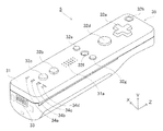
次に、図4〜図7を参照して、コントローラ5について説明する。図4は、コントロー
ラ5の外観構成を示す斜視図である。図5は、コントローラ5の外観構成を示す斜視図で
ある。図4は、コントローラ5の上側後方から見た斜視図であり、図5は、コントローラ
5を下側前方から見た斜視図である。
[Configuration of controller 5]
Next, the
図4および図5において、コントローラ5は、例えばプラスチック成型によって形成さ
れたハウジング31を有している。ハウジング31は、その前後方向(図4に示すZ軸方
向)を長手方向とした略直方体形状を有しており、全体として大人や子供の片手で把持可
能な大きさである。ユーザ(プレイヤ)は、コントローラ5に設けられたボタンを押下す
ること、および、コントローラ5自体を動かしてその位置や姿勢を変えることによってゲ
ーム操作を行うことができる。
4 and 5, the
ハウジング31には、複数の操作ボタンが設けられる。図4に示すように、ハウジング
31の上面には、十字ボタン32a、1番ボタン32b、2番ボタン32c、Aボタン3
2d、マイナスボタン32e、ホームボタン32f、プラスボタン32g、および電源ボ
タン32hが設けられる。本明細書では、これらのボタン32a〜32hが設けられるハ
ウジング31の上面を「ボタン面」と呼ぶことがある。一方、図5に示すように、ハウジ
ング31の下面には凹部が形成されており、当該凹部の後面側傾斜面にはBボタン32i
が設けられる。これらの各操作ボタン32a〜32iには、ゲーム装置3が実行するゲー
ムプログラムに応じた機能が適宜割り当てられる。また、電源ボタン32hは遠隔からゲ
ーム装置3本体の電源をオン/オフするためのものである。ホームボタン32fおよび電
源ボタン32hは、その上面がハウジング31の上面に埋没している。これによって、プ
レイヤがホームボタン32fまたは電源ボタン32hを誤って押下することを防止するこ
とができる。
The
2d, a
Is provided. A function corresponding to the game program executed by the
ハウジング31の後面にはコネクタ33が設けられている。コネクタ33は、コントロ
ーラ5に他の機器を接続するために利用される。また、ハウジング31の後面におけるコ
ネクタ33の両側には、上記他の機器が容易に離脱することを防止するために係止穴33
aが設けられている。
A
a is provided.
ハウジング31上面の後方には複数(図4では4つ)のLED34a〜34dが設けら
れる。ここで、コントローラ5には、他のメインコントローラと区別するためにコントロ
ーラ種別(番号)が付与される。各LED34a〜34dは、コントローラ5に現在設定
されている上記コントローラ種別をプレイヤに通知したり、コントローラ5の電池残量を
プレイヤに通知したりする等の目的で用いられる。具体的には、コントローラ5を用いて
ゲーム操作が行われる際、上記コントローラ種別に応じて複数のLED34a〜34dの
いずれか1つが点灯する。
A plurality (four in FIG. 4) of
また、コントローラ5は撮像情報演算部35(図7)を有しており、図5に示すように
、ハウジング31前面には撮像情報演算部35の光入射面35aが設けられる。光入射面
35aは、マーカ6Rおよび6Lからの赤外光を少なくとも透過する材質で構成される。
Further, the
ハウジング31上面における1番ボタン32bとホームボタン32fとの間には、コン
トローラ5に内蔵されるスピーカ49(図6)からの音を外部に放出するための音抜き孔
31aが形成されている。
A
次に、図6および図7を参照して、コントローラ5の内部構造について説明する。図6
および図7は、コントローラ5の内部構造を示す図である。なお、図6は、コントローラ
5の上筐体(ハウジング31の一部)を外した状態を示す斜視図である。図7は、コント
ローラ5の下筐体(ハウジング31の一部)を外した状態を示す斜視図である。図7に示
す斜視図は、図6に示す基板30を裏面から見た斜視図となっている。
Next, the internal structure of the
FIG. 7 is a diagram showing the internal structure of the
図6において、ハウジング31の内部には基板30が固設されており、当該基板30の
上主面上に各操作ボタン32a〜32h、各LED34a〜34d、加速度センサ37、
アンテナ45、およびスピーカ49等が設けられる。これらは、基板30等に形成された
配線(図示せず)によってマイクロコンピュータ(Micro Computer:マイ
コン)42(図7参照)に接続される。本実施形態では、加速度センサ37は、X軸方向
に関してコントローラ5の中心からずれた位置に配置されている。これによって、コント
ローラ5をZ軸回りに回転させたときのコントローラ5の動きが算出しやすくなる。また
、加速度センサ37は、長手方向(Z軸方向)に関してコントローラ5の中心よりも前方
に配置されている。また、無線モジュール44(図7)およびアンテナ45によって、コ
ントローラ5がワイヤレスコントローラとして機能する。
In FIG. 6, a
An
一方、図7において、基板30の下主面上の前端縁に撮像情報演算部35が設けられる
。撮像情報演算部35は、コントローラ5の前方から順に赤外線フィルタ38、レンズ3
9、撮像素子40、および画像処理回路41を備えている。これらの部材38〜41はそ
れぞれ基板30の下主面に取り付けられる。
On the other hand, in FIG. 7, an imaging
9, an
さらに、基板30の下主面上には、上記マイコン42およびバイブレータ48が設けら
れている。バイブレータ48は、例えば振動モータやソレノイドであり、基板30等に形
成された配線によってマイコン42と接続される。マイコン42の指示によりバイブレー
タ48が作動することによってコントローラ5に振動が発生する。これによって、コント
ローラ5を把持しているプレイヤの手にその振動が伝達される、いわゆる振動対応ゲーム
を実現することができる。本実施形態では、バイブレータ48は、ハウジング31のやや
前方寄りに配置される。つまり、バイブレータ48がコントローラ5の中心よりも端側に
配置することによって、バイブレータ48の振動によりコントローラ5全体を大きく振動
させることができる。また、コネクタ33は、基板30の下主面上の後端縁に取り付けら
れる。なお、図6および図7に示す他、コントローラ5は、マイコン42の基本クロック
を生成する水晶振動子、スピーカ49に音声信号を出力するアンプ等を備えている。
Further, the
なお、図4〜図7に示したコントローラ5の形状や、各操作ボタンの形状、加速度セン
サやバイブレータの数および設置位置等は単なる一例に過ぎず、他の形状、数、および設
置位置であっても、本発明を実現することができる。また、本実施形態では、撮像手段に
よる撮像方向はZ軸正方向であるが、撮像方向はいずれの方向であってもよい。すなわち
、コントローラ5における撮像情報演算部35の位置(撮像情報演算部35の光入射面3
5a)は、ハウジング31の前面でなくてもよく、ハウジング31の外部から光を取り入
れることができれば他の面に設けられてもかまわない。
Note that the shape of the
5a) may not be the front surface of the
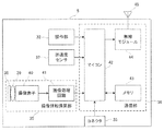
図8は、コントローラ5の構成を示すブロック図である。コントローラ5は、操作部3
2(各操作ボタン32a〜32i)、コネクタ33、撮像情報演算部35、通信部36、
および加速度センサ37を備えている。コントローラ5は、自機に対して行われた操作内
容を示すデータを操作データとしてゲーム装置3へ送信するものである。
FIG. 8 is a block diagram showing the configuration of the
2 (each
And an
操作部32は、上述した各操作ボタン32a〜32iを含み、各操作ボタン32a〜3
2iに対する入力状態(各操作ボタン32a〜32iが押下されたか否か)を示す操作ボ
タンデータを通信部36のマイコン42へ出力する。
The
Operation button data indicating an input state for 2i (whether or not each of the
撮像情報演算部35は、撮像手段が撮像した画像データを解析してその中で輝度が高い
領域を判別してその領域の重心位置やサイズなどを算出するためのシステムである。撮像
情報演算部35は、例えば最大200フレーム/秒程度のサンプリング周期を有するので
、比較的高速なコントローラ5の動きでも追跡して解析することができる。
The imaging
撮像情報演算部35は、赤外線フィルタ38、レンズ39、撮像素子40、および画像
処理回路41を含んでいる。赤外線フィルタ38は、コントローラ5の前方から入射する
光から赤外線のみを通過させる。レンズ39は、赤外線フィルタ38を透過した赤外線を
集光して撮像素子40へ入射させる。撮像素子40は、例えばCMOSセンサやあるいは
CCDセンサのような固体撮像素子であり、レンズ39が集光した赤外線を受光して画像
信号を出力する。ここで、テレビ2の表示画面近傍に配置されるマーカ装置6のマーカ6
Rおよび6Lは、テレビ2の前方に向かって赤外光を出力する赤外LEDで構成される。
したがって、赤外線フィルタ38を設けることによって、撮像素子40は、赤外線フィル
タ38を通過した赤外線だけを受光して画像データを生成するので、マーカ6Rおよび6
Lの画像をより正確に撮像することができる。以下では、撮像素子40によって撮像され
た画像を撮像画像と呼ぶ。撮像素子40によって生成された画像データは、画像処理回路
41で処理される。画像処理回路41は、撮像画像内における撮像対象(マーカ6Rおよ
び6L)の位置を算出する。画像処理回路41は、算出された位置を示す座標を通信部3
6のマイコン42へ出力する。この座標のデータは、マイコン42によって操作データと
してゲーム装置3に送信される。以下では、上記座標を「マーカ座標」と呼ぶ。マーカ座
標はコントローラ5自体の向き(傾斜角度)や位置に対応して変化するので、ゲーム装置
3はこのマーカ座標を用いてコントローラ5の向きや位置を算出することができる。
The imaging
R and 6L are composed of infrared LEDs that output infrared light toward the front of the
Therefore, by providing the
L images can be taken more accurately. Hereinafter, an image captured by the
6 to the
なお、他の実施形態においては、コントローラ5は画像処理回路41を備えていない構
成であってもよく、撮像画像自体がコントローラ5からゲーム装置3へ送信されてもよい
。このとき、ゲーム装置3は、画像処理回路41と同様の機能を有する回路あるいはプロ
グラムを有しており、上記マーカ座標を算出するようにしてもよい。
In other embodiments, the
加速度センサ37は、コントローラ5の加速度(重力加速度を含む)を検出する、すな
わち、コントローラ5に加わる力(重力を含む)を検出する。加速度センサ37は、当該
加速度センサ37の検出部に加わっている加速度のうち、センシング軸方向に沿った直線
方向の加速度(直線加速度)の値を検出する。例えば、2軸以上の多軸加速度センサの場
合には、加速度センサの検出部に加わっている加速度として、各軸に沿った成分の加速度
をそれぞれ検出する。例えば、3軸または2軸の加速度センサは、アナログ・デバイセズ
株式会社(Analog Devices, Inc.)またはSTマイクロエレクトロ
ニクス社(STMicroelectronics N.V.)から入手可能である種類
のものでもよい。なお、加速度センサ37は、例えば静電容量式の加速度センサであると
するが、他の方式の加速度センサを用いるようにしてもよい。
The
本実施形態では、加速度センサ37は、コントローラ5を基準とした上下方向(図4に
示すY軸方向)、左右方向(図4に示すX軸方向)および前後方向(図4に示すZ軸方向
)の3軸方向に関してそれぞれ直線加速度を検出する。加速度センサ37は、各軸に沿っ
た直線方向に関する加速度を検出するものであるため、加速度センサ37からの出力は3
軸それぞれの直線加速度の値を表すものとなる。すなわち、検出された加速度は、コント
ローラ5を基準に設定されるXYZ座標系(コントローラ座標系)における3次元のベク
トル(ax,ay,az)として表される。以下では、加速度センサ37によって検出さ
れる3軸に関する各加速度値を各成分とするベクトルを加速度ベクトルと呼ぶ。
In the present embodiment, the
It represents the linear acceleration value of each axis. That is, the detected acceleration is expressed as a three-dimensional vector (ax, ay, az) in an XYZ coordinate system (controller coordinate system) set with the
加速度センサ37が検出した加速度を示すデータ(加速度データ)は、通信部36へ出
力される。なお、加速度センサ37が検出した加速度は、コントローラ5自体の向き(傾
斜角度)や動きに対応して変化するので、ゲーム装置3は加速度データを用いてコントロ
ーラ5の向きや動きを算出することができる。本実施形態では、ゲーム装置3は、加速度
データに基づいてコントローラ5の姿勢(傾斜角度)を判断する。つまり、加速度センサ
37は、コントローラ5の傾斜角度を判断するためのデータを出力するセンサとして用い
られる。
Data indicating the acceleration detected by the acceleration sensor 37 (acceleration data) is output to the
なお、加速度センサ37から出力される加速度の信号に基づいて、ゲーム装置3のプロ
セッサ(例えばCPU10)またはコントローラ5のプロセッサ(例えばマイコン42)
等のコンピュータが処理を行うことによって、コントローラ5に関するさらなる情報を推
測または算出(判定)することができることは、当業者であれば本明細書の説明から容易
に理解できるであろう。例えば、加速度センサ37を搭載するコントローラ5が静止状態
であることを前提としてコンピュータ側の処理が実行される場合(すなわち、加速度セン
サによって検出される加速度が重力加速度のみであるとして処理が実行される場合)、コ
ントローラ5が現実に静止状態であれば、検出された加速度に基づいてコントローラ5の
姿勢が重力方向に対して傾いているか否かまたはどの程度傾いているかを知ることができ
る。具体的には、加速度センサ37の検出軸が鉛直下方向を向いている状態を基準とした
とき、1G(重力加速度)がかかっているか否かによって、コントローラ5が基準に対し
て傾いているか否かを知ることができるし、その大きさによって基準に対してどの程度傾
いているかも知ることができる。また、多軸の加速度センサ37の場合には、さらに各軸
の加速度の信号に対して処理を施すことによって、重力方向に対してコントローラ5がど
の程度傾いているかをより詳細に知ることができる。この場合において、プロセッサは、
加速度センサ37からの出力に基づいてコントローラ5の傾斜角度を算出してもよいし、
当該傾斜角度を算出せずに、コントローラ5の傾斜方向を算出するようにしてもよい。こ
のように、加速度センサ37をプロセッサと組み合わせて用いることによって、コントロ
ーラ5の傾斜角度または姿勢を判定することができる。
Note that, based on the acceleration signal output from the
Those skilled in the art can easily understand from the description of the present specification that further information regarding the
The tilt angle of the
The tilt direction of the
一方、コントローラ5が動的な状態(コントローラ5が動かされている状態)であるこ
とを前提とする場合には、加速度センサ37は重力加速度に加えてコントローラ5の動き
に応じた加速度を検出するので、検出された加速度から重力加速度の成分を所定の処理に
より除去することによってコントローラ5の動き方向を知ることができる。また、コント
ローラ5が動的な状態であることを前提とする場合であっても、検出された加速度から、
加速度センサの動きに応じた加速度の成分を所定の処理により除去することによって、重
力方向に対するコントローラ5の傾きを知ることが可能である。なお、他の実施例では、
加速度センサ37は、内蔵の加速度検出手段で検出された加速度信号をマイコン42に出
力する前に当該加速度信号に対して所定の処理を行うための、組込み式の処理装置または
他の種類の専用の処理装置を備えていてもよい。組込み式または専用の処理装置は、例え
ば、加速度センサ37が静的な加速度(例えば、重力加速度)を検出するために用いられ
る場合、加速度信号を傾斜角(あるいは、他の好ましいパラメータ)に変換するものであ
ってもよい。
On the other hand, when it is assumed that the
By removing the acceleration component according to the motion of the acceleration sensor by a predetermined process, it is possible to know the inclination of the
The
なお、本実施形態では、コントローラの動きに応じて変化する値を出力するセンサとし
て、例えば静電容量式の加速度センサを用いることとしたが、他の方式の加速度センサや
ジャイロセンサを用いるようにしてもよい。ただし、加速度センサは各軸に沿った直線方
向の加速度をそれぞれ検出するものであるのに対して、ジャイロセンサは回転に伴う角速
度を検出するものである。つまり、加速度センサに代えてジャイロセンサを採用する場合
には、検出される信号の性質が異なるため、両者を簡単に置き換えることはできない。そ
こで、加速度センサの代わりにジャイロセンサを用いて姿勢(傾斜角度)を算出する場合
には、例えば次のような変更を行う。具体的には、ゲーム装置3は、検出開始の状態にお
いて姿勢の値を初期化する。そして、当該ジャイロセンサから出力される角速度のデータ
を積分する。さらに、積分結果を用いて、初期化された姿勢の値からの姿勢の変化量を算
出する。この場合、算出される姿勢は、角度で表されることになる。
In this embodiment, for example, a capacitance type acceleration sensor is used as a sensor that outputs a value that changes in accordance with the movement of the controller. However, other types of acceleration sensors or gyro sensors are used. May be. However, the acceleration sensor detects acceleration in a linear direction along each axis, whereas the gyro sensor detects angular velocity associated with rotation. In other words, when a gyro sensor is employed instead of the acceleration sensor, the nature of the detected signal is different, and therefore both cannot be easily replaced. Therefore, when calculating the attitude (tilt angle) using a gyro sensor instead of the acceleration sensor, for example, the following changes are made. Specifically, the
なお、既に説明したように、加速度センサによって傾斜角度(姿勢)を算出する場合に
は、加速度ベクトルを用いて傾斜角度を算出する。したがって、算出される傾斜角度はベ
クトルで表すことが可能であり、初期化を行わずとも絶対的な方向を算出することが可能
である点で、加速度センサを用いる場合とジャイロセンサを用いる場合とは異なる。また
、傾斜角度として算出される値の性質についても上記のように角度であるかベクトルであ
るかの違いがあるので、加速度センサからジャイロセンサへの置き換えを行う際には当該
傾斜角度のデータに対しても所定の変換を行う必要がある。
As already described, when the inclination angle (posture) is calculated by the acceleration sensor, the inclination angle is calculated using the acceleration vector. Therefore, the calculated tilt angle can be expressed as a vector, and the absolute direction can be calculated without performing initialization. In the case of using an acceleration sensor and the case of using a gyro sensor. Is different. In addition, since the property of the value calculated as the tilt angle also differs depending on whether it is an angle or a vector as described above, when replacing the acceleration sensor with the gyro sensor, the data of the tilt angle is included. Even for this, it is necessary to perform predetermined conversion.
通信部36は、マイコン42、メモリ43、無線モジュール44、およびアンテナ45
を含んでいる。マイコン42は、処理を行う際にメモリ43を記憶領域として用いながら
、マイコン42が取得したデータをゲーム装置3へ無線送信する無線モジュール44を制
御する。また、マイコン42はコネクタ33に接続されている。
The
Is included. The
操作部32、撮像情報演算部35、および加速度センサ37からマイコン42へ出力さ
れたデータは、一時的にメモリ43に格納される。これらのデータは、上記操作データと
してゲーム装置3へ送信される。すなわち、マイコン42は、ゲーム装置3の無線コント
ローラモジュール19への送信タイミングが到来すると、メモリ43に格納されている操
作データを無線モジュール44へ出力する。無線モジュール44は、例えばBlueto
oth(ブルートゥース)(登録商標)の技術を用いて、所定周波数の搬送波を操作デー
タで変調し、その微弱電波信号をアンテナ45から放射する。つまり、操作データは、無
線モジュール44で微弱電波信号に変調されてコントローラ5から送信される。微弱電波
信号はゲーム装置3側の無線コントローラモジュール19で受信される。受信された微弱
電波信号について復調や復号を行うことによって、ゲーム装置3は操作データを取得する
ことができる。そして、ゲーム装置3のCPU10は、取得した操作データとゲームプロ
グラムとに基づいて、ゲーム処理を行う。なお、通信部36から無線コントローラモジュ
ール19への無線送信は所定の周期毎に逐次行われるが、ゲームの処理は1/60秒を単
位として(1フレーム時間として)行われることが一般的であるので、この時間以下の周
期で送信を行うことが好ましい。コントローラ5の通信部36は、例えば1/200秒に
1回の割合で各操作データをゲーム装置3の無線コントローラモジュール19へ出力する
。
Data output from the
Using a technology of oth (Bluetooth) (registered trademark), a carrier wave of a predetermined frequency is modulated with operation data, and the weak radio signal is radiated from the
上記コントローラ5を用いることによって、プレイヤは、各操作ボタンを押下する従来
の一般的なゲーム操作に加えて、コントローラ5を任意の傾斜角度に傾ける操作を行うこ
とができる。その他、上記コントローラ5によれば、プレイヤは、コントローラ5によっ
て画面上の任意の位置を指示する操作、および、コントローラ5自体を動かす操作を行う
こともできる。
By using the
[照明装置9の構成]
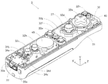
次に、図9から図15を参照して、照明装置9の構成について説明する。図9は、照明
装置9の外観図である。また、図10は、照明装置9内の主要な構成を示す斜視図である
。図9において、照明装置9は、筐体51、カバー52、軸頭部53、支持軸54、支持
部材55、および8個の光モジュール61〜68を備えている。照明装置9は、可視光を
出射するものであり、テレビ2の後方の壁面に可視光を投光することで、テレビ2に表示
される画像に加えてさらなる視覚効果をユーザに与えるものである。なお、上述のように
照明装置9はスピーカ112を備えているが、図10ではスピーカ112は表されていな
い。照明装置9内におけるスピーカ112の配置位置は任意であり、筐体51内の空きス
ペースに適宜取り付けられる。
[Configuration of Lighting Device 9]
Next, the configuration of the
図9に示すように、筐体51は上面(図9に示すy軸正方向側の面)が開口しており、
筐体51の内部には、支持軸54、支持部材55、および8個の光モジュール61〜68
が設置される。支持部材55の上には、8つの光モジュール61〜68(図3に示す各光
モジュール)が取り付けられる。詳細は後述するが、各光モジュール61〜68はそれぞ
れ可視光を出射する部材である。また、支持部材55および各光モジュール61〜68の
上方にある開口部には、透明なカバー52が取り付けられている。したがって、各光モジ
ュール61〜68から出射された光は、カバー52を透過して筐体51の外部へ出射され
る。なお、他の実施形態においては、照明装置9はカバー52を備えていない構成であっ
てもよく、光モジュール61〜68の出射面が外部に露出していてもよい。
As shown in FIG. 9, the
Inside the
Is installed. On the
また、図10に示すように、支持部材55は、その両端(図10に示すx軸方向の端部
)で支持軸54に接続されている。支持軸54は、筐体51の側面に設けられた穴に挿入
されている。したがって、支持部材55は筐体51によって(x軸まわりに)回転可能に
支持されている。また、支持軸54は、筐体51の外側で軸頭部53と接続されている。
したがって、ユーザは、軸頭部53を回転させることによって支持部材55を回転させる
(傾きを変化させる)ことができる。以上のように、照明装置9は支持部材55および支
持軸54を含むチルト機構を有しているので、ユーザは、支持部材55の傾きを変化させ
ることによって、各光モジュール61〜68の出射方向を変化させることができる。
As shown in FIG. 10, the
Therefore, the user can rotate the supporting member 55 (change the inclination) by rotating the
次に、光モジュールの内部構造について説明する。上記各光モジュール61〜68のう
ち、概ね同じ向き(正確には異なっている)に配置された7つの光モジュール61〜67
は、光の断面が長手形状(線状)となる光(後述する「線状光」)を出射する。これら7
つの光モジュール61〜67は、それぞれ同じ構成を有している。一方、光モジュール6
8は、光モジュール61〜67による光よりも断面が広い光(後述する「背景光」)を出
射する。以下では、光モジュール61〜67と光モジュール68とを区別する目的で、前
者を「線状光モジュール」と呼び、後者を「背景光モジュール」と呼ぶことがある。
Next, the internal structure of the optical module will be described. Among the
Emits light ("linear light" to be described later) having a cross section of light having a longitudinal shape (linear shape). These 7
The two
8 emits light having a wider cross section than the light from the
図11は、線状光モジュールの内部構造を示す図である。図11において、線状光モジ
ュール61は、筐体71、カラーLEDモジュール72、集光レンズ73、および拡散シ
ート74を備えている。なお、図11では、線状光モジュール61の内部構成を示すが、
他の線状光モジュール62〜67の内部構成も図11と同様である。
FIG. 11 is a diagram illustrating an internal structure of the linear optical module. In FIG. 11, the linear
The internal configurations of the other linear
図11に示すように、筐体71は、上面が開口した箱状の形状である。筐体71内の基
板(底部)には、カラーLEDモジュール72が取り付けられる。カラーLEDモジュー
ル72は、複数種類の色の光を発光可能である。本実施形態では、カラーLEDモジュー
ル72は、赤色LED75と緑色LED76と青色LED77とを有しており、各LED
75〜77の発光強度(例えばそれぞれ256段階)をマイコン28(図2)が適宜調整
することによって所望の色で発光することが可能である。3つのLED75〜77は、一
列に(図11では、a軸方向に平行な軸Lに沿って一列に)配置される。
As shown in FIG. 11, the
The microcomputer 28 (FIG. 2) appropriately adjusts the light emission intensities of 75 to 77 (for example, 256 levels each) so that light can be emitted in a desired color. The three
カラーLED72の上方には、集光レンズ73が設置される。図11では、集光レンズ
73は筐体71の開口部に取り付けられる。本実施形態では、集光レンズ73は、一方向
にのみ光を集束させる。本実施形態では、集光レンズ73の集束方向(レンズが曲率を有
する方向)は、図11に示すc軸方向である(図11に示す矢印参照)。また、本実施形
態では、光モジュール61の小型化を図るべく、集光レンズ73としてフレネルレンズ(
リニアフレネルレンズ)を用いる。他の実施形態においては、リニアフレネルレンズに代
えて凸シリンドリカルレンズを集光レンズ73として用いてもよい。
A condensing
Linear Fresnel lens) is used. In another embodiment, a convex cylindrical lens may be used as the condensing
集光レンズ73の上側には、拡散シート74が取り付けられる。拡散シート74は、集
光レンズ73の集束方向とは垂直な方向、すなわち、a軸方向にのみ光を拡散する。なお
、他の実施形態においては、拡散シート74に代えて凹シリンドリカルレンズを用いても
よい。
A
図12は、線状光モジュールから出射される光を示す図である。図11に示すように、
カラーLEDモジュール72からの光は、集光レンズ73によってc軸方向に集光される
とともに、拡散シート74によってa軸方向に拡散される。これによって、線状光モジュ
ールから出射される光の断面形状は、図12に示すように、a軸方向に長く、c軸方向に
短い長手形状(線状)となる。ここで、「光の断面形状」とは、光の進行方向に対して垂
直な面に当該光を当てた時の形状を指す。以下では、断面形状が長手形状(線状)となる
光を「線状光」と呼ぶ。
FIG. 12 is a diagram illustrating light emitted from the linear optical module. As shown in FIG.
Light from the
また、本実施形態においては、集光レンズ73の集束方向(図11に示す矢印)は、上
記3つのLED75〜77の配置方向(図11に示す軸Lの方向)に対して垂直である。
すなわち、3つのLED75〜77はa軸方向に平行な軸Lに沿って並んで配置されるの
に対して、集光レンズ73は、集束方向がa軸方向に垂直なc軸方向となるように設置さ
れる。これは、3つのLED75〜77からの3つの光をずれが生じることなく混色し、
壁面に投光された線状光をきれいに見せる(単一の色に見せる)ためである。ここで、仮
に3つのLED75〜77が軸Lに関してずれて配置される場合には、各LED75〜7
7から集光レンズ73を透過して出射される光がc軸方向に関してずれてしまう。図13
は、3つのLED75〜77が軸Lからずれて配置される場合に投光される線状光の一例
を示す図である。上記の場合、各LED75〜77からの3つの光は、c軸方向に関して
ずれて壁面に投光されてしまう結果、図13に示すように、中央の領域81では3つの光
の色が混ざるものの、線状光の短手方向に関して端部の領域82においては3つの光の色
が混ざらなくなってしまう。これに対して、本実施形態では、各LED75〜77を集光
レンズ73の集束方向に垂直な方向に配置することによって、投光された各光の短手方向
の位置を一致させ、投光された光をきれいに見せることができる。
In the present embodiment, the focusing direction of the condenser lens 73 (arrow shown in FIG. 11) is perpendicular to the arrangement direction of the three
That is, the three
This is because the linear light projected on the wall surface is clearly displayed (a single color is displayed). Here, if the three
The light emitted from 7 through the
These are figures which show an example of the linear light projected when three LED75-77 is shifted | deviated from the axis | shaft L and is arrange | positioned. In the above case, the three lights from the
なお、本実施形態では、壁面に線状光を投光すべく、集光レンズ73および拡散シート
74を用いることとした。ここで、他の実施形態においては、線状光はどのような方法で
作成されてもよい。例えば、線状光は、拡散シート74を用いずに集光レンズ73のみを
用いて作成されてもよいし、集光レンズ73および拡散シート74に代えてスリットを用
いて作成されてもよい。また、線状光モジュール61〜67は、LEDによる光に代えて
レーザ光を投光することで線状光を実現するようにしてもよい。
In the present embodiment, the condensing
また、背景光モジュール68は、線状光モジュール61〜67による光よりも断面が広
い光(背景光)を出射する。本実施形態では、背景光モジュール68は、筐体とカラーL
EDモジュールとを備える構成であり、集光レンズおよび拡散シートを有していない。な
お、背景光モジュール68のカラーLEDモジュールは、赤色、緑色、および青色の3つ
のLEDを有するが、これらのLEDとしては、線状光モジュール61〜67で使用され
るLEDに比べて、高輝度かつ広角に発光するものが用いられる。本実施形態では、背景
光モジュール68は、線状光モジュール61〜67の光の強度よりも小さい強度で光を出
射することで、線状光を背景光に比べて目立たせるようにしている。逆に、背景光モジュ
ール68の光の強度を線状光モジュール61〜67の光の強度よりも強くすれば、背景光
を目立たせることができる。また、背景光または線状光の一方のみを投光するようにして
もよい。なお、他の実施形態においては、背景光モジュール68においても線状光モジュ
ール61〜67と同様に、集光レンズを用いてもよいし、集光レンズおよび拡散シートを
用いてもよい。集光レンズを用いる場合における集束方向は、線状光モジュール61〜6
7における集束方向と同様である。また、拡散シートは、縦および横の両方向に光を拡散
するものが用いられる。
The
It is a structure provided with an ED module, and does not have a condensing lens and a diffusion sheet. The color LED module of the
7 is the same as the focusing direction. In addition, a diffusion sheet that diffuses light in both the vertical and horizontal directions is used.
次に、図14を参照して、照明装置9内における各光モジュール61〜68の配置を説
明する。図14は、各光モジュールの配置を示す3面図である。図14に示す(a)図は
、y軸正側(上側)から各光モジュール61〜68を見た図であり、(b)図は、z軸負
側(前側)から各光モジュール61〜68を見た図であり、(c)図は、x軸負側から各
光モジュール61〜68を見た図である。なお、図14では、説明の理解を容易にする目
的で、光モジュール64の出射方向が鉛直上向きとなる状態を示しているが、実際には、
照明装置9から後方の斜め上方に向けて光が出射されるように、各光モジュール61〜6
8は傾いて配置される。
Next, with reference to FIG. 14, arrangement | positioning of each optical module 61-68 in the illuminating
Each of the
8 is inclined and arranged.
線状光モジュール61〜68は、照明装置9の後方の斜め上方に向けて、照明装置9を
略中心として放射状となるようにそれぞれの線状光を出射する。具体的には、図14の(
a)図および(b)図に示すように、各線状光モジュール61〜67は、x軸方向(左右
方向)に並んで配置され、線状光モジュール64を中心としてyz平面に対して対称に配
置される。また、図14の(a)図のように上側(y軸正側)から見た場合、各線状光モ
ジュール61〜67は、各線状光モジュール61〜67の出射面の長手方向(線状光の長
手方向)が照明装置9の後方の所定位置を中心とした略放射状の向きとなるように配置さ
れる。すなわち、上側から見た場合、各線状光モジュール61〜67は、外側に配置され
るモジュールほど、後端(z軸正側の端部)が内側を向くように傾いて配置される。さら
に、図14の(b)図のように前側から見た場合、各線状光モジュール61〜67は、各
線状光モジュール61〜67の出射方向が照明装置9の下方の所定位置を中心とした略放
射状となるように配置される。すなわち、前側から見た場合、各線状光モジュール61〜
67は、外側に配置されるモジュールほど出射方向が外側を向くように傾いて配置される
。
The linear
As shown in FIGS. a and b, the linear
67 is arranged so that the module arranged on the outside is inclined such that the emission direction faces the outside.
また、背景光モジュール68は、線状光モジュール61〜67が出射する各線状光と重
なる向きへ背景光を出射する。具体的には、図14の(a)図のように、背景光モジュー
ル68は、x軸方向(左右方向)に関して各線状光モジュール61〜67の略中心に配置
される。また、背景光モジュール68は、z軸方向(前後方向)に関しては各線状光モジ
ュール61〜67より後方に配置される。さらに、図14の(c)図のように、背景光モ
ジュール68は、出射方向が線状光モジュール64よりもやや下向きとなるように傾いて
配置される。他の実施形態においては、背景光モジュール68が、出射方向が線状光モジ
ュール64よりも上向きとなってもよいし、ほぼ同じ方向となるようにしてもよい。
The
図15は、照明装置9によってテレビ2の背面に投光された線状光および背景光を示す
図である。図15において、領域91は線状光モジュール61からの光が投光される領域
であり、領域92は線状光モジュール62からの光が投光される領域であり、領域93は
線状光モジュール63からの光が投光される領域であり、領域94は線状光モジュール6
4からの光が投光される領域であり、領域95は線状光モジュール65からの光が投光さ
れる領域であり、領域96は線状光モジュール66からの光が投光される領域であり、領
域97は線状光モジュール67からの光が投光される領域であり、領域98は線状光モジ
ュール68からの光が投光される領域である。図15に示すように、本実施形態では、テ
レビ2の背面に光が投光されるので、テレビ2の前側から見ると表示画面の周りに光によ
って装飾が施されているように見え、表示画面に対して効果的な照明効果(装飾効果)を
付与することができる。また、仮に照明装置9の光をユーザに向けて(前方に向けて)出
射する場合には、ユーザにとっては照明装置9の一点のみが光って見えるにすぎず、表示
画面に対する装飾効果としては効果が小さいものになってしまう。これに対して、本実施
形態においては、照明装置9の光を後方に向けて出射することで、壁面に光を投光し、壁
面に当たった光をユーザに見せるようにしている。そのため、テレビ2の表示画面よりも
広い範囲にわたる光をユーザに見せることも可能であり、高い装飾効果を得ることができ
る。
FIG. 15 is a diagram showing linear light and background light projected onto the back surface of the
4 is a region where light from the linear
各線状光モジュール61〜67を図14に示す配置とすることによって、図15に示す
ように、照明装置9の後方の斜め上方に向けて、照明装置9を略中心とした放射状となる
ように線状光を投光することができる。本実施形態によれば、照明装置9は複数の線状光
を投光するので、1つの光のみを投光する場合に比べて、投光パターンを増やすことがで
き、照明効果のバリエーションを増やすことができる。
By arranging each of the linear
一般的には、テレビ2の後方には、平面状の壁が存在する場合の他、凹角となった壁が
存在する場合(典型的には部屋の隅にテレビ2が置かれる場合)や、カーテンが存在する
場合等、壁面に凹凸がある場合も考えられる。このように壁面に凹凸がある場合には、凹
凸があるために投光した光に歪みが生じるおそれがある。例えば横長の光(断面が水平方
向に長い光)を凹凸がある壁面に対して投光すると、投光された光が1本の線状には見え
なくなる。また例えば、複数の光を水平に並ぶように出射しても、投光面に凹凸があると
、投光された光は水平には並ばなくなってしまう。これに対して、本実施形態では、照明
装置9は放射状となるように複数の線状光を投光するので、テレビ2の後方にある投光面
の凹凸による線状光の歪みが目立たず、壁面の状態が異なっていても同じような放射状の
線状光を投光することができる。例えば、部屋の角に向けて複数の線状光を出射しても、
平面上に出射した場合にくらべて放射状の線の開き方が異なるだけで線自体はまっすぐに
投光されることになるので、見た目の違和感が少ない。また、カーテン等の面は、一般的
には横方向に関する凹凸がほとんどで、縦方向にはそれほど凹凸を形成しないものである
ので、同様に線状光の見た目が線状に近いまま投光することができる。
In general, behind the
Compared to the case of emission on a flat surface, the radial lines are projected straight only by the way the radial lines are opened, so that the visual discomfort is less. Further, since the surface of the curtain or the like generally has most unevenness in the horizontal direction and does not form so much unevenness in the vertical direction, similarly, light is projected while the appearance of linear light is close to linear. be able to.
また、図15に示すように、本実施形態では、背景光モジュール68を図14に示す配
置とすることによって、壁面において線状光と背景光とを重ねて投光することができる。
したがって、照明装置9は、線状光の色だけでなく、その背景の色をも制御することがで
きるので、線状光のみを制御する場合に比べて投光パターンを増やすことができ、照明効
果のバリエーションを増やすことができる。また、本実施形態では、背景光モジュール6
8の光の強度を線状光モジュール61〜67の光の強度よりも小さく設定するので、背景
光と線状光の両方が投光される領域は、線状光の色に見える。つまり、壁面には背景光の
上に線状光が重ねて投光されているように見える。
As shown in FIG. 15, in this embodiment, the
Therefore, the
Since the intensity of the light No. 8 is set to be smaller than the intensity of the light of the linear
なお、図14に示す各光モジュール61〜68の配置は一例であり、各線状光モジュー
ル61〜67は、テレビ2の後方の壁面に対して、照明装置9を略中心とした放射状とな
るように線状光を投光するように配置されれば、どのように配置されてもよい。また、他
の実施形態においては、各線状光モジュール61〜67は、例えば各線状光が平行に並ん
で投光されるように配置されてもよいし、各線状光が所定の形状を表すように配置されて
もよい。一方、背景光モジュール68は、線状光モジュール61〜67の光と重なる方向
へ光を出射するように配置されれば、どのように配置されてもよい。また、他の実施形態
においては、各線状光モジュール61〜67のうちいくつかの線状光モジュールの光と重
なる方向へ光を出射するように背景光モジュール68が配置されてもよい。
Note that the arrangement of the
[照明装置9の制御に関するゲーム装置3の処理]
次に、照明装置9に対する制御に関する処理を中心に、ゲーム装置3において実行され
る処理について説明する。本実施形態では、ゲーム装置3は、光ディスク4に記憶された
ゲームプログラムに従ってゲーム処理を実行する際に、テレビ2にゲーム画像を表示する
とともに、照明装置9を用いて照明効果を付加する。また、ゲーム装置3は、テレビ2が
テレビ放送の番組の画像を表示している場合に、照明装置9を用いて照明効果を付加する
。以下、ゲームを実行する際における照明装置9の制御、および、テレビ番組の画像が表
示される際における照明装置9の制御を中心に、ゲーム装置3が実行する処理について説
明する。
[Processing of
Next, the process performed in the
(ゲームを実行する際におけるゲーム装置3の処理)
以下、ゲームを実行する際におけるゲーム装置3の処理について説明する。まず、当該
処理において用いられる主なデータについて図16を用いて説明する。図16は、ゲーム
装置3のメインメモリ(外部メインメモリ12または内部メインメモリ11e)に記憶さ
れる主なデータを示す図である。図16に示すように、ゲーム装置3のメインメモリには
、ゲームプログラム101、操作データ102、および処理用データ106が記憶される
。なお、メインメモリには、図16に示すデータの他、ゲームに登場する各種オブジェク
トの画像データや、オブジェクトの各種パラメータを示すデータ等、ゲーム処理に必要な
データが記憶される。
(Processing of
Hereinafter, processing of the
ゲームプログラム101は、ゲーム装置3が上述した通常モードとなった後の適宜のタ
イミングで光ディスク4からその一部または全部が読み込まれてメインメモリに記憶され
る。ゲームプログラム101には、ゲーム処理を実行するプログラム、および、ゲーム処
理に応じて照明装置9の発光を制御するプログラム(後述するステップS5)が含まれる
。
Part or all of the
操作データ102は、コントローラ5からゲーム装置3へ送信されてくる操作データで
ある。上述したように、コントローラ5からゲーム装置3へ1/200秒に1回の割合で
操作データが送信されるので、メインメモリに記憶される操作データ102はこの割合で
更新される。操作データ102には、操作ボタンデータ103、マーカ座標データ104
、および加速度データ105が含まれる。
The
, And
操作ボタンデータ103は、各操作ボタン32a〜32iに対する入力状態を示すデー
タである。すなわち、操作ボタンデータ103は、各操作ボタン32a〜32iが押下さ
れているか否かを示す。
The
マーカ座標データ104は、撮像情報演算部35の画像処理回路41によって算出され
る座標、すなわち上記マーカ座標を示すデータである。マーカ座標は、撮像画像に対応す
る平面上の位置を表すための2次元座標系で表現される。なお、撮像素子40によって2
つのマーカ6Rおよび6L(赤外光)が撮像される場合には、2つのマーカ座標が算出さ
れる。一方、撮像素子40の撮像可能な範囲内にマーカ6Rおよび6Lのいずれか一方が
位置しない場合には、撮像素子40によって1つのマーカのみが撮像され、1つのマーカ
座標のみが算出される。また、撮像素子40の撮像可能な範囲内にマーカ6Rおよび6L
の両方が位置しない場合には、撮像素子40によってマーカが撮像されず、マーカ座標は
算出されない。したがって、マーカ座標データ104は、2つのマーカ座標を示す場合も
あるし、1つのマーカ座標を示す場合もあるし、マーカ座標がないことを示す場合もある
。
The marker coordinate
When two
If neither of these is located, the marker is not imaged by the
加速度データ105は、加速度センサ37によって検出された加速度(加速度ベクトル
)を示すデータである。ここでは、加速度データ105は、図4に示すXYZの3軸の方
向に関する加速度を各成分とする3次元の加速度ベクトルを示す。
The
処理用データ106は、後述するゲーム処理(図17)において用いられるデータであ
る。処理用データ106は、ゲームデータ107および発光制御データ108を含む。ゲ
ームデータ107は、ゲームパラメータのデータであり、照明装置9に対する制御に影響
を与えるゲームパラメータのデータである。例えば、ゲームデータ107は、ゲームに登
場するキャラクタのパラメータを示すデータであってもよいし、画面上に表示されるカー
ソルの位置を示すデータであってもよい。
The
発光制御データ108は、照明装置9の発光を制御するためのデータである。本実施形
態では、発光制御データ108は、照明装置9の各光モジュール29が発光すべき光の色
および強さを示す。具体的には、例えば赤、緑、青の各LEDの発光強度が256段階で
示されている。詳細は後述するが、発光制御データ108は、照明装置9へ送信されてマ
イコン28にて取得され、マイコン28は発光制御データ108に従って各光モジュール
29を制御する。
The light
次に、ゲーム装置3において行われる処理の詳細を、図17を用いて説明する。図17
は、ゲームを実行する際にゲーム装置3において実行される処理の流れを示すフローチャ
ートである。上記通常モードにおいてユーザからゲーム装置3に対してゲームの開始指示
が入力されると、ゲーム装置3のCPU10は、図示しないブートROMに記憶されてい
る起動プログラムを実行し、これによってメインメモリ等の各ユニットが初期化される。
そして、光ディスク4に記憶されたゲームプログラムがメインメモリに読み込まれ、CP
U10によって当該ゲームプログラムの実行が開始される。図17に示すフローチャート
は、以上の処理が完了した後に行われる処理を示すフローチャートである。
Next, details of processing performed in the
These are flowcharts which show the flow of the process performed in the
Then, the game program stored on the optical disc 4 is read into the main memory, and the CP
Execution of the game program is started by U10. The flowchart shown in FIG. 17 is a flowchart showing a process performed after the above process is completed.
まず、ステップS1において、CPU10は、ゲームに関する初期化処理を実行する。
この初期化処理においては、ゲーム処理に用いられる各種パラメータの値が初期化された
り、仮想のゲーム空間が構築されたり、プレイヤオブジェクトや他のオブジェクトがゲー
ム空間の初期位置に配置されたりする。ステップS1の後、ステップS2〜S6の処理ル
ープが、ゲームが実行される間繰り返し実行される。なお、1回の当該処理ループは、1
フレーム時間(例えば1/60秒)に1回の割合で実行される。
First, in step S1, the
In this initialization process, the values of various parameters used in the game process are initialized, a virtual game space is constructed, and player objects and other objects are placed at initial positions in the game space. After step S1, the processing loop of steps S2 to S6 is repeatedly executed while the game is executed. One processing loop is 1
It is executed once per frame time (for example, 1/60 seconds).
ステップS2において、CPU10は操作データを取得する。すなわち、コントローラ
5から送信されてくる操作データが無線コントローラモジュール19を介して受信される
。そして、受信された操作データに含まれる操作ボタンデータ、マーカ座標データ、およ
び加速度データがそれぞれメインメモリに記憶される。ステップS2の次にステップS3
の処理が実行される。
In step S2, the
The process is executed.
ステップS3において、CPU10は、ステップS2で取得された操作データに基づい
てゲーム処理を実行する。具体的には、例えば操作データに基づいてゲームキャラクタの
動作を制御する処理を実行したり、画面上に表示されるカーソルの位置を操作データ(特
に例えばマーカ座標データ104)に基づいて算出する処理を実行したりする。このとき
、ゲーム処理の結果得られるゲームデータ107がメインメモリに記憶される。上記ステ
ップS3の次にステップS4の処理が実行される。
In step S3, the
ステップS4において、CPU10は、ステップS3で実行されたゲーム処理に応じた
ゲーム画像をテレビ2の画面に表示する。具体的には、CPU10(およびGPU11b
)は、メインメモリからゲームデータ107を読み出し、ゲームデータ107等に基づい
てゲーム画像を生成して画面に表示する。ゲーム画像は、例えば、ゲームキャラクタを含
むゲーム空間の画像であってもよいし、当該画像に重ねてカーソルの画像を含むものであ
ってもよい。また、ステップS4において、CPU10(およびDSP11c)は、ゲー
ム処理に応じたゲーム音をゲームデータ107等に基づいて生成し、スピーカ2aから出
力する。なお、ゲーム音は、ゲーム中のBGMであってもよいし、ゲームの効果音であっ
てもよいし、ゲームキャラクタの声等であってもよい。上記ステップS4の次に、ステッ
プS5の処理が実行される。
In step S <b> 4, the
) Reads out the
ステップS5において、CPU10は、照明装置9による発光を制御する。すなわち、
CPU10は、メインメモリからゲームデータ107を読み出し、各光モジュール29が
発光すべき光の色および強さを示す発光制御データ108をゲームデータ107に基づい
て生成する。生成された発光制御データ108は、メインメモリに記憶され、入出力プロ
セッサ11aによって拡張コネクタ20を介して照明装置9へ送信される。発光制御デー
タ108を受信した照明装置9のマイコン28は、当該発光制御データ108に従って各
光モジュール29の発光を制御する。なお、照明装置9へ発光制御データ108を送信す
る時間間隔はいくらでもよいが、本実施形態では、ゲーム画像の更新間隔(1/60秒)
と同じであるとする。このように、発光制御データ108が繰り返し送信されることによ
って、ゲーム装置3は、照明装置9による投光を変化させることができ、例えばゲーム状
況、ゲーム画像、ゲーム音、およびゲーム操作等に応じた照明効果をユーザに与えること
ができる。上記ステップS5の次に、ステップS6の処理が実行される。
In step S <b> 5, the
The
Is the same. As described above, by repeatedly transmitting the light
上記ステップS5において、CPU10は、照明装置9の発光状態をステップS3のゲ
ーム処理に応じて決定する。例えば、照明装置9の発光状態は、ゲーム状況、ゲーム画像
、ゲーム音、およびゲーム操作等に基づいて決定される。照明装置9の具体的な制御例と
しては例えば以下が挙げられる。
(1)ゲーム画像(ゲーム状況)に応じた制御例
CPU10は、画面におけるゲーム画像(ゲーム状況)の変化に応じて照明装置9の発
光状態(光の強さ、色、および発光パターン等)を変化させる。例えば格闘ゲームにおい
て、キャラクタの攻撃が他のキャラクタにヒットしたことに応じて照明装置9の発光状態
を変化させてもよいし、射撃ゲームにおいて標的に弾が命中したことに応じて照明装置9
の発光状態を変化させてもよい。これによれば、ゲーム画像の変化に応じた照明効果を付
加することによって、ゲーム画像に効果的な照明効果を付加することができる。
(2)ゲーム操作に応じた制御例
CPU10は、ユーザのゲーム操作に応じて、照明装置9の発光状態を変化させる。具
体的には、CPU10は、ユーザがコントローラ5の操作ボタンを押下したことに応じて
各光モジュール61〜68を発光させたり、光の色を変化させたりしてもよい。
また、コントローラ5の操作に応じて画面上のカーソルの位置が制御される場合には、
CPU10は、画面におけるカーソルの位置に応じて、各光モジュール61〜68の発光
状態を変化させてもよい。例えば、画面を横方向に7分割した領域を線状光モジュール6
1〜67に1つずつ対応させ、カーソル位置を含む領域に対応する線状光モジュールのみ
を発光させるようにしてもよい。
(3)ゲーム音に応じた制御例
CPU10は、ゲーム中で流れるBGM等の音楽に合わせて照明装置9の発光状態を変
化させる。具体的には、音楽のリズムに合わせて光モジュール61〜68を点滅させたり
、出力される音の音程(音高)に合わせて発光パターンおよび/または発光色を変化させ
たりする。また、ユーザによるゲーム操作に応じて音楽が演奏される演奏ゲームにおいて
、演奏される音楽に合わせて照明装置9を制御するようにしてもよい。これによれば、ユ
ーザは、自己の操作によって演奏される音楽を聴覚だけでなく視覚でも楽しむことができ
る。
In step S5, the
(1) Control example according to game image (game situation) The
The light emission state may be changed. According to this, an effective lighting effect can be added to the game image by adding the lighting effect according to the change of the game image.
(2) Control example according to game operation CPU10 changes the light emission state of the illuminating
When the position of the cursor on the screen is controlled according to the operation of the
CPU10 may change the light emission state of each optical module 61-68 according to the position of the cursor in a screen. For example, a region obtained by dividing the screen into seven in the horizontal direction is a linear
1 to 67 one by one, and only the linear optical module corresponding to the region including the cursor position may be caused to emit light.
(3) Control example according to game sound CPU10 changes the light emission state of the illuminating
ステップS6において、CPU31は、ゲームを終了するか否かを判定する。ステップ
S6の判定は、例えば、ゲームがクリアされたか否か、ゲームオーバーとなったか否か、
ユーザがゲームを中止する指示を行ったか否か等によって行われる。ステップS6の判定
結果が否定である場合、ステップS2の処理が再度実行される。以降、ステップS6でゲ
ームを終了すると判定されるまで、ステップS2〜S6の処理ループが繰り返し実行され
る。一方、ステップS6の判定結果が肯定である場合、CPU31は、図17に示すゲー
ム処理を終了する。以上で、ゲーム処理の説明を終了する。
In step S6, the
This is performed depending on whether or not the user gives an instruction to stop the game. If the determination result of step S6 is negative, the process of step S2 is executed again. Thereafter, the processing loop of steps S2 to S6 is repeatedly executed until it is determined in step S6 that the game is to be ended. On the other hand, when the determination result of step S6 is affirmative, the
以上のように、本実施形態によれば、ゲーム画像がテレビ2に表示されるとともに、テ
レビ2の後方の壁面には、照明装置9による投光によって照明効果が付加される。これに
よれば、ゲーム画像に加えてさらなる視覚的効果をユーザに与えることができるので、ゲ
ームの迫力や臨場感をより向上することができる。
As described above, according to the present embodiment, a game image is displayed on the
(テレビ番組の画像が表示される際におけるゲーム装置3の処理)
次に、図18および図19を参照して、テレビ番組の画像が表示される際におけるゲー
ム装置3の処理について説明する。図18は、テレビ番組の画像が表示される際にゲーム
装置3において実行される処理の流れを示すメインフローチャートである。また、図19
は、図18に示す処理が実行される際におけるゲーム装置3と他の装置との間のデータの
流れを示す図である。
(Processing of
Next, with reference to FIG. 18 and FIG. 19, processing of the
FIG. 19 is a diagram showing a data flow between the
本実施形態では、ゲーム装置3は、テレビ視聴用のアプリケーションを記憶している。
上記通常モードにおいて当該アプリケーションの開始指示がユーザによって入力されると
、ゲーム装置3は当該アプリケーションの実行を開始する。すなわち、メインメモリ等の
各ユニットが初期化された後、当該アプリケーションのプログラムがメインメモリに読み
込まれ、CPU10によって当該プログラムの実行が開始される。図18に示すフローチ
ャートは、以上の処理が完了した後に行われる処理を示すフローチャートである。なお、
図18においては、上記アプリケーションによる処理のうち、照明装置9の制御に関する
処理のみを記載するが、上記アプリケーションは、例えばEPG(電子番組表)を表示し
たり、テレビ2に対する指示(チャンネルの選局や音量の変更等)を行ったりする機能を
有していてもよい。
In the present embodiment, the
When an instruction to start the application is input by the user in the normal mode, the
In FIG. 18, only the processing related to the control of the
なお、本実施形態では、図18に示す処理が実行される前に(すなわち、上記アプリケ
ーションの開始指示を行う前に)、ユーザは、テレビ2の電源をオンにし、所望のチャン
ネルの番組を表示させておくこととする。
In the present embodiment, before the processing shown in FIG. 18 is executed (that is, before the application start instruction is given), the user turns on the
図18においては、まずステップS11において、CPU10は、テレビ2で表示して
いるチャンネルの入力を受け付ける(ユーザにチャンネルを入力させる)。すなわち、C
PU10は、上記ステップS2と同様の処理によって操作データを取得し、チャンネルを
入力するユーザ指示を受け付ける。このとき、ユーザは、テレビ2で表示されているチャ
ンネルを入力する。なお、ユーザにチャンネルの入力を行わせるためのインターフェース
は、どのようなものであってもよい。例えば、CPU10は、コントローラ5の各ボタン
に対してチャンネルを予め割り当てておき、入力すべきチャンネルに対応するボタンをユ
ーザに押下させるようにしてもよい。これによれば、テレビ2にテレビ番組の画像を表示
したままでチャンネルの入力を行わせることができる。また、例えば、CPU10は、テ
レビ番組の画像の表示を一旦切り替えて入力用の画像をテレビ2に表示させ、当該画像を
用いてユーザにチャンネルの入力を行わせてもよい。具体的には、CPU10は、EPG
の画像をテレビ2に表示させ、所望の番組をユーザに選択させることによってチャンネル
を特定するようにしてもよい。CPU10は、入力されたチャンネルを示すデータをチャ
ンネルデータとしてメインメモリに記憶しておく。ステップS11の次にステップS12
の処理が実行される。
In FIG. 18, first, in step S <b> 11, the
The
The image may be displayed on the
The process is executed.
また、ゲーム装置3がテレビ2に対する指示を行うことが可能な場合には、ステップS
11において、CPU10は、ユーザによって入力されたチャンネルを選局するようにテ
レビ2に指示を行ってもよい。これによれば、ユーザは、テレビ2のチャンネルを予め所
望のチャンネルに合わせておく必要がなく、テレビ2とゲーム装置3との両方に対するチ
ャンネルの指示を1回の操作で行うことができる。なお、ゲーム装置3がテレビ2に対す
る指示を行う方法としては、テレビ2のリモコンから出力される赤外線信号と同様の信号
をマーカ装置6から出力させる方法が考えられる。マーカ装置6から出力された赤外線信
号は、直接、または、テレビ2の周囲の壁面等に反射して、テレビ2の赤外線受光部で受
光されるので、ゲーム装置3はテレビ2に対して指示を行うことができる。
If the
11, the
ステップS12において、CPU10は、上述した指示データを取得する要求(取得要
求)をサーバ110に対して行う。具体的には、CPU10は、メインメモリから上記チ
ャンネルデータを読み出して、取得要求を示すデータ(取得要求データ)を生成し、取得
要求データをネットワーク111を介してサーバ110へ送信する。この取得要求データ
には、指示データの送信先を示すデータ(ゲーム装置3を識別することが可能な情報を示
す)と、ステップS11で入力されたチャンネルを示すデータとが含まれる。ステップS
12の次にステップS13の処理が実行される。
In step S <b> 12, the
Next to 12, the process of step S13 is executed.
図19に示すように、上記取得要求データがゲーム装置3からサーバ110へ送信され
た場合(ステップS21)、サーバ110は、送信元のゲーム装置3に対して指示データ
を送信する(ステップS22)。指示データは、上述したように、照明装置9を発光させ
る指示を示すデータである。本実施形態では、指示データは、照明装置9の各光モジュー
ル29が発光すべき光の色を示し、より具体的には、赤、緑、および青の各LEDの発光
強度を256段階で示す。また、本実施形態では、指示データは、所定時間間隔で(例え
ば、テレビの画像のフレームレートに合わせて1/60秒間隔で)繰り返し送信される。
したがって、サーバ110は、指示データを繰り返し送信することで、照明装置9の発光
状態(換言すれば、照明装置9による照明効果)を動的に変化させることができる。なお
、他の実施形態においては、サーバ110は、複数個の指示データをまとめてゲーム装置
3へ送信するようにしてもよい。
As shown in FIG. 19, when the acquisition request data is transmitted from the
Therefore, the
また、サーバ110は、テレビ放送のチャンネル毎に異なる指示データを記憶しており
、受信した取得要求データが示すチャンネルに対応する指示データを送信する。したがっ
て、サーバ110は、チャンネル毎に(すなわち、番組毎に)異なる発光パターンで照明
装置9を発光させることができ、チャンネル毎に異なる照明効果を与えることができる。
なお、他の実施形態においては、サーバ110は、全チャンネルの指示データを送信し、
各指示データを受信したゲーム装置3が、必要な指示データ(ステップS11で入力され
たチャンネルの指示データ)を選択して利用するようにしてもよい。この場合、上記取得
要求データは、チャンネルを示すデータを含まなくてもよい。
The
In another embodiment, the
The
図18の説明に戻り、ステップS13において、CPU10は、サーバ110からの指
示データを受信する。すなわち、サーバ110から送信されてきた指示データはアンテナ
22および無線通信モジュール18を介してフラッシュメモリ17に記憶されるので、C
PU10はフラッシュメモリ17から指示データを取得する。なお、ステップS13〜S
17の処理ループは、上記指示データの送信間隔(例えば1/60秒間隔)に合わせた時
間間隔に1回の割合で実行される。したがって、ステップS13において、CPU10は
、サーバ110から順次送信されてくる指示データを順次受信する。ステップS13の次
にステップS14の処理が実行される。
Returning to the description of FIG. 18, in step S <b> 13, the
The
Seventeen processing loops are executed at a rate of once per time interval that matches the transmission interval (for example, 1/60 second interval) of the instruction data. Accordingly, in step S <b> 13, the
ステップS14において、CPU10は、ステップS13で受信した指示データに従っ
て照明装置9による発光を制御する。具体的には、まず、CPU10は、上記指示データ
に基づいて発光制御データを生成する。本実施形態では、指示データは、照明装置9の各
光モジュール29が発光すべき光の色を示すのに対して、発光制御データは、各光モジュ
ール29が発光すべき光の色および強さを示す。したがって、CPU10は、指示データ
に対して、光の強さを示す情報を付加することによって発光制御データを生成する。ここ
で、付加すべき光の強さは、ユーザによって予め設定されているものとする。つまり、本
実施形態では、照明装置9が発光する色やパターンはサーバ110において決められ、発
光する光の強さはユーザが適宜調整可能である。これによって、ユーザは、自分の好みに
合わせて、または、テレビ2の周囲の環境に応じた適切な光の強さとなるように、照明装
置9を調整することができる。
In step S14, the
なお、他の実施形態においては、指示データは、照明装置9が発光するパターンのみを
示し、発光する色および強さはゲーム装置3においてユーザによって決められるようにし
てもよい。また、他の実施形態においては、指示データと発光制御データとは同じ内容で
あるとしてもよい。すなわち、照明装置9の発光パターン、光の色、および光の強さが指
示データによって決められてもよい。
In other embodiments, the instruction data may indicate only the pattern that the
以上のようにして発光制御データを生成すると、CPU10は次に、発光制御データを
照明装置9へ送信することによって照明装置9を発光させる。発光制御データを送信する
処理は、上記ステップS5における処理と同じである。以上のステップS14の次に、ス
テップS15の処理が実行される。
After generating the light emission control data as described above, the
上記ステップS14の処理によって、図19に示すように、ゲーム装置3から照明装置
9へ発光制御データが送信される(ステップS23)。発光制御データを受信した照明装
置9のマイコン28は、当該発光制御データに従って各光モジュール29の発光を制御す
る。指示データがサーバ110からゲーム装置3へ繰り返し送信され、指示データの送信
に合わせてステップS13〜S17の処理ループが繰り返し実行されるので、図19に示
すように、発光制御データは照明装置9へ繰り返し送信される。したがって、ゲーム装置
3は、照明装置9による投光を動的に変化させることができ、テレビ番組の内容あるいは
画像の内容に応じて変化するように照明装置9による照明効果を与えることができる。
As a result of the process in step S14, the light emission control data is transmitted from the
なお、サーバ110から送信される各指示データにより指示される発光パターン等の具
体的な内容は、テレビ番組の画像および/または音声に応じたものであればどのようなも
のであってもよい。各指示データは、例えば、テレビ番組の場面(シーン)が変わる毎に
、発光状態を変化させるものであってもよいし、画像に応じて発光状態を変化させるもの
であってもよいし、番組中のBGMや効果音に合わせて発光状態を変化させるものであっ
てもよい。
The specific contents such as the light emission pattern indicated by each instruction data transmitted from the
図18の説明に戻り、ステップS15において、CPU10は操作データを取得する。
ステップS15の処理は、上述したステップS2(図17)と同じである。ステップS1
5の次にステップS16の処理が実行される。
Returning to FIG. 18, in step S <b> 15, the
The process of step S15 is the same as step S2 (FIG. 17) described above. Step S1
Next to 5, the process of step S16 is executed.
ステップS16において、CPU10は、上記ステップS15で取得された操作データ
に基づいて、チャンネルを変更する指示が行われたか否かを判定する。ユーザは、テレビ
2のチャンネルを変更した場合、ゲーム装置3に対してもチャンネルを変更する指示を行
う。ユーザにチャンネルの変更を行わせるためのインターフェースはどのようなものであ
ってもよいが、例えばステップS11におけるインターフェースと同じ方法を用いればよ
い。なお、チャンネルを変更するユーザ指示が行われた場合、CPU10は、入力された
チャンネルを示すデータを新たなチャンネルデータとしてメインメモリに記憶しておく。
ステップS16の判定結果が肯定である場合、ステップS17の処理が実行される。一方
、ステップS16の判定結果が否定である場合、後述するステップS18の処理が実行さ
れる。
In step S16, the
If the determination result of step S16 is affirmative, the process of step S17 is executed. On the other hand, when the determination result of step S16 is negative, a process of step S18 described later is executed.
ステップS17において、CPU10は、送信すべき指示データのチャンネルを変更す
る要求(変更要求)をサーバ110に対して行う。具体的には、CPU10は、メインメ
モリから上記チャンネルデータを読み出して、変更要求を示すデータ(変更要求データ)
を生成し、ネットワーク111を介してサーバ110へ変更要求データを送信する。変更
要求データの内容は、上記取得要求データと同じであり、指示データの送信先を示すデー
タと、ステップS16における変更後のチャンネルを示すデータとが含まれる。上記ステ
ップS17の後、ステップS13の処理が再度実行される。
In step S <b> 17, the
And the change request data is transmitted to the
図19において、上記変更要求データがゲーム装置3からサーバ110へ送信された場
合(ステップS24)、サーバ110は、送信元のゲーム装置3に対して指示データを送
信する(ステップS25)。ここで、送信される指示データは、変更要求データにより示
されるチャンネルに対応する指示データである。また、ステップS25の場合も上記ステ
ップS22の場合と同様、指示データは、所定時間間隔で繰り返し送信される。
In FIG. 19, when the change request data is transmitted from the
ゲーム装置3のCPU10は、上記ステップS17の後、ステップS13およびS14
の処理を再度実行する。したがって、CPU10は、変更要求データに応じてサーバから
順次送信されてくる指示データを順次受信し(ステップS13)、受信した指示データに
応じた発光制御データを照明装置9へ送信することによって照明装置9を制御する(ステ
ップS14,ステップS26)。したがって、ユーザがチャンネルを変更した場合には、
変更後のチャンネルに応じた内容で照明装置9による照明効果が付加される。
The
Execute the process again. Therefore, the
The lighting effect by the
図18の説明に戻り、ステップS18において、CPU10は、照明装置9による照明
効果の付与を終了する指示がユーザからあったか否かを判定する。この判定は、上記ステ
ップS15で取得されてメインメモリに記憶された操作データに基づいて行われる。具体
的には、CPU10は、操作データに含まれる操作ボタンデータ103を参照し、コント
ローラ5の所定のボタンが押下されたか否かを判定する。なお、照明効果の付与を終了す
る指示は、例えば、アプリケーションを終了する指示でも良いし、アプリケーションの終
了とは別に照明装置9の駆動を終了する指示でもよい。ステップS18の判定結果が肯定
である場合、ステップS19の処理が実行される。一方、ステップS18の判定結果が否
定である場合、ステップS13の処理が再度実行される。
Returning to the description of FIG. 18, in step S <b> 18, the
ステップS19において、CPU10は、指示データの送信を終了する要求(終了要求
)をサーバ110に対して行う。具体的には、CPU10は、終了要求を示すデータ(終
了要求データ)を生成し、ネットワーク111を介してサーバ110へ送信する。なお、
終了要求データは、終了要求の要求元を示すデータ(ゲーム装置3を識別することが可能
な情報を示す)を含んでいればよい。ステップS19の終了後、CPU10は、図18に
示す処理を終了する。
In step S <b> 19, the
The end request data only needs to include data indicating the request source of the end request (indicating information capable of identifying the game apparatus 3). After the end of step S19, the
図19に示すように、上記終了要求データがゲーム装置3からサーバ110へ送信され
た場合(ステップS27)、サーバ110は、送信元のゲーム装置3に対して指示データ
を送信することを終了する。以上で、テレビ番組の画像が表示される際におけるゲーム装
置3の処理の説明を終了する。
As shown in FIG. 19, when the end request data is transmitted from the
以上のように、図18および図19に示した処理によれば、ゲーム装置3は、テレビ番
組の画像に対しても照明装置9を用いて照明効果を付加することができ、テレビ番組の迫
力や臨場感をより向上することができる。また、上記実施形態においては、サーバ110
は、テレビ放送のチャンネル毎、および、時間毎に異なる指示データをするので、当該指
示データを受信したゲーム装置3は、テレビ放送の番組毎に、その内容に応じた照明効果
を付与することができる。
As described above, according to the processing shown in FIGS. 18 and 19, the
Since different instruction data is provided for each television broadcast channel and each time, the
なお、上記実施形態では、本発明に係る情報処理装置の一例であるゲーム装置3は、ゲ
ームの実行中にゲーム画像に対して照明効果を付加する処理と、テレビ番組の視聴中にテ
レビ番組の画像に対して照明効果を付加する処理との両方を行うものとした。ここで、他
の実施形態においては、情報処理装置は、どちらか一方の処理のみを実行可能であっても
よい。なお、テレビ番組の画像に対して照明効果を付加する処理のみを実行可能である場
合、情報処理装置は、テレビと電気的に接続されている必要はない。
In the above embodiment, the
[他の実施形態]
上記実施形態は本発明を実施する一例であり、他の実施形態においては例えば以下に説
明する構成で本発明を実施することも可能である。
[Other embodiments]
The above-described embodiment is an example for carrying out the present invention. In other embodiments, the present invention can be implemented with, for example, the configuration described below.
(テレビ放送と照明装置の投光との同期に関する変形例)
上記実施形態では、ステップS22およびS25において、サーバ110は、リアルタ
イムのテレビ番組に合わせて指示データを送信する。つまり、サーバ110は、指示デー
タがゲーム装置3で受信されて直ちに利用されることを想定したタイミングで、指示デー
タを送信する。そのため、ゲーム装置3は、テレビ番組の画像を表示するタイミングと、
照明装置9を発光させるタイミングとの間の同期をとる処理を実行しない。したがって、
本実施形態では、テレビ番組の画像を表示するタイミングと、照明装置9を発光させるタ
イミングとの間で若干のずれが生じる可能性がある。しかし、テレビ番組の画像(および
/または音声)に応じて照明装置9の投光が変化すれば、照明装置9による演出効果は十
分得られるので、上記2つのタイミングに多少のずれが生じても問題はないと考えられる
。なお、サーバ110は、上記のずれをできるだけ低減するために、サーバ110とゲー
ム装置3との間の通信時間や、テレビ2がテレビ番組の画像をデコードするのに要する時
間等を考慮して、指示データを送信するタイミングを調整してもよい。
(Variation regarding synchronization between TV broadcasting and lighting of lighting device)
In the above embodiment, in steps S22 and S25, the
Processing to synchronize with the timing for causing the
In the present embodiment, there may be a slight difference between the timing for displaying the image of the television program and the timing for causing the
以上のように、本実施形態では、ゲーム装置3は、テレビ番組の画像を表示するタイミ
ングと、照明装置9を発光させるタイミングとの間の同期処理を行わない。ただし、他の
実施形態においては、ゲーム装置3側で同期処理を行うようにしてもよい。例えば、指示
データに時刻データを含ませておき、ゲーム装置3は、デジタル放送において送信される
放送データに含まれる時刻情報と同期させて指示データを用いてもよい。すなわち、ゲー
ム装置3は、テレビ放送のデータに含まれる時刻データと、指示データに含まれる時刻デ
ータとを用いて、両者の時刻データが一致するように、テレビ番組の画像の表示タイミン
グと照明装置9の投光タイミングとを同期させる。これによれば、ゲーム装置3はより正
確に同期を取ることができる。
As described above, in the present embodiment, the
(指示データの送信タイミングに関する変形例)
上記実施形態では、サーバ110は、リアルタイムの(現在放送中の)テレビ番組に対
応する指示データを送信するものとしたが、他の実施形態においては、開始前のテレビ番
組に対応する指示データを送信するようにしてもよい。この場合、サーバ110は、(現
在より後の)所定の時間帯のテレビ番組に対応する指示データを各チャンネルについて送
信する。なお、各指示データには、それを利用すべき時刻を示す時刻データが含まれてい
るものとする。ゲーム装置3は、当該指示データを受信し、メインメモリ等に記憶してお
く。そして、上記ステップS11におけるチャンネルの入力があった場合、CPU10は
、入力があったチャンネルの指示データであって、時刻データが現在時刻を示す指示デー
タをメインメモリから読み出し、当該指示データに従って照明装置9を制御する。これに
よれば、サーバ110は、指示データをゲーム装置3へ予め送信しておくことができる。
(Modified example of instruction data transmission timing)
In the above embodiment, the
また、サーバ110が開始前のテレビ番組に対応する指示データを送信する場合には、
ゲーム装置3は、指示データを受信する処理を上記スリープモードにおいても実行するよ
うにしてもよい。なお、ゲーム装置3が指示データの受信処理をスリープモード時におい
て実行する場合には、当該受信処理は一定時間間隔で実行されるとよい。また、上記の場
合、ゲーム装置3は、例えば上記アプリケーションにおいてEPGのデータとともに、指
示データを受信するようにしてもよい。
Further, when the
The
(照明装置9の音声出力に関する変形例)
上記実施形態では、ゲーム装置3が照明装置9による投光を制御する処理について説明
したが、他の実施形態においては、ゲーム装置3は、照明装置9のスピーカ112による
音声出力をさらに制御してもよい。すなわち、上記指示データには、テレビ放送の画像お
よび/または音声に合わせてスピーカ11に音を出力させる指示を示すデータ(音指示デ
ータ)が含まれていてもよい。なお、音指示データは、例えば音の波形を示すデータでも
よいし、MIDIデータであってもよい。CPU10は、受信した指示データに従ってス
ピーカ112に音を出力させる。具体的には、CPU10は、スピーカ112が出力すべ
き音を制御する音制御データを、受信した指示データに基づいて生成する。そして、上記
発光制御データに加えて音制御データを照明装置9へさらに送信する。スピーカ112は
、受信した音制御データに従って音を出力する。これによれば、ゲーム装置3は、照明装
置9によって、視覚的効果に加え、聴覚的効果をもユーザに与えることができる。なお、
上記音指示データ(および音制御データ)の内容はどのようなものであってもよいが、テ
レビ番組の画像および音声に対して演出効果を追加することを鑑みれば、音指示データは
、テレビ番組の音声とは異なる音を出力させる指示を示すものであることが好ましい。ま
た、単なる個別のシーンに演出音声を追加するだけでなく、テレビ番組には含まれていな
い立体音響に対応した音声等を別途出力して、テレビの音声に替えて、もしくはテレビの
音声と合わせて利用されるようにしてもよい。したがって、スピーカ112は複数設けら
れていてもよい。
(Modification regarding sound output of lighting device 9)
In the above embodiment, the process in which the
The contents of the sound instruction data (and sound control data) may be anything, but in view of adding a production effect to the image and sound of a television program, the sound instruction data is a television program. It is preferable to indicate an instruction to output a sound different from the voice. In addition to adding production audio to individual scenes, it also outputs audio that is compatible with stereophonic sound that is not included in TV programs, and replaces it with TV audio or matches it with TV audio. May be used. Therefore, a plurality of
また、照明装置9のスピーカ112を制御する処理は、テレビ番組を表示する場合(図
18)だけでなく、ゲーム画像を表示する場合(図17)においても実行されてもよい。
なお、ゲーム画像を表示する場合においては、上記音制御データは、ゲーム処理に応じた
音が出力されるように、CPU10によって適宜生成される。
Further, the process of controlling the
When displaying a game image, the sound control data is appropriately generated by the
(ゲーム画像以外の画像に応じて照明装置9を駆動させる変形例)
上記実施形態においては、テレビ2の画面にゲーム画像が表示される時、および、テレ
ビ番組の画像が表示される時に照明装置9が照明効果を付加する場合を説明したが、テレ
ビ2の画面に表示される画像はゲーム画像やテレビ番組の画像に限らず、ゲーム画像以外
の動画や静止画であってもよい。例えば、ゲーム装置3は、ネットワークを介して外部の
他のゲーム装置やサーバから画像を取得し、当該画像をテレビ2に表示する時に照明装置
9による照明効果を付加してもよい。この場合、ゲーム装置3は、照明装置9の発光を制
御するためのデータ(上記発光制御データ108)を、画像とともに取得してもよいし、
画像の取得元とは別の装置やサーバから取得してもよい。また、ゲーム装置3は、予め定
められたアルゴリズムに従って、取得された画像から発光制御データを自動的に作成する
ようにしてもよい。
(Modification in which the
In the above embodiment, the case where the
You may acquire from the apparatus and server different from the acquisition source of an image. Further, the
(ユーザに対する通知のために照明装置9を発光させる変形例)
また、照明装置9は、テレビ2に表示される画像に対してさらなる視覚的効果を付加す
る目的の他、ユーザに対する通知を行う目的で利用されてもよい。本実施形態においては
、ゲーム装置3は、上述したスリープモードで動作することが可能である。スリープモー
ド時においてはCPU10は動作しないので、ゲーム処理やゲーム画像の表示は実行され
ないが、入出力プロセッサ11aによってネットワークを介して外部の装置(他のゲーム
装置またはサーバ装置等)との通信が実行される。例えば、ゲーム装置3は、ユーザが作
成した(電子メール形式の)メッセージを他のゲーム装置との間で送受信したり、サーバ
装置からゲームプログラムや動画のデータを受信したりすることをスリープモード時にお
いて行う。本変形例では、ゲーム装置3は、スリープモード時において他のゲーム装置か
らのメッセージを受信した場合に、受信したことを通知するために照明装置9を発光させ
る。以下、詳細を説明する。
(Modification in which the
In addition to the purpose of adding a further visual effect to the image displayed on the
図18は、スリープモード時における入出力プロセッサ11aのデータ受信処理を示す
フローチャートである。スリープモード時において、入出力プロセッサ11aは、図18
に示す処理を所定のタイミング(例えば、所定時間に1回の割合)で実行する。なお、図
18は、スリープモード時における処理を示しているが、入出力プロセッサ11aは通常
モード時においても外部の装置との通信を行う。
FIG. 18 is a flowchart showing data reception processing of the input /
Is executed at a predetermined timing (for example, once every predetermined time). FIG. 18 shows processing in the sleep mode, but the input /
ステップS31において、入出力プロセッサ11aは、メッセージを保存・管理するメ
ールサーバにアクセスし、自機(ゲーム装置3)宛のメッセージがあるかどうかを確認す
る。続くステップS32において、入出力プロセッサ11aは、ステップS31の確認の
結果、受信メッセージがあったか否かを判定する。受信メッセージがある場合、ステップ
S33の処理が実行される。一方、受信メッセージがない場合、入出力プロセッサ11a
は、図18に示すデータ受信処理を終了する。
In step S31, the input /
Ends the data reception process shown in FIG.
ステップS33において、入出力プロセッサ11aは、メールサーバからメッセージを
受信する。すなわち、入出力プロセッサ11aは、メールサーバにアクセスして受信した
メッセージをフラッシュメモリ17に記憶する。ステップS33の次にステップS34の
処理が実行される。
In step S33, the input /
ステップS34において、入出力プロセッサ11aは、照明装置9による発光を開始す
る。具体的には、入出力プロセッサ11aは、上記発光制御データを作成して拡張コネク
タ20を介して照明装置9へ送信する。発光制御データを受信した照明装置9のマイコン
28は、当該発光制御データに従って各光モジュール29の発光を制御する。以降、入出
力プロセッサ11aは、繰り返し発光制御データを送信することによって、照明装置9に
よる発光を継続する。したがって、ユーザは、照明装置9による発光によって、メッセー
ジが届いていることを知ることができる。以上のステップS34の後、入出力プロセッサ
は図18に示すデータ受信処理を終了する。
In step S34, the input /
なお、上記ステップS34において、入出力プロセッサ11aは、データの受信状態に
応じて照明装置9の発光状態(光の強さ、色、および発光パターン等)を変化させてもよ
い。例えば、受信したメッセージの数、メッセージの送信元、および、受信したデータの
種類(メッセージであるか、ゲームに関するデータであるか等)に応じて照明装置9の発
光状態を変化させてもよい。これによれば、ユーザは、どのようなデータを受信したか等
、受信データの情報を照明装置9の発光状態によって知ることができる。
In step S34, the input /
以上のように、上記変形例によれば、ゲーム装置3は、メッセージを受信したことに応
じて照明装置9を発光させることによって、メッセージの受信をユーザに通知することが
できる。なお、上記変形例では、ゲーム装置3は、メッセージを受信したことに応じて照
明装置9を発光させるようにしたが、他の実施形態においては、メッセージのデータに加
えて、または、メッセージのデータに代えて、他のデータ(例えば、サーバから送信され
てくるゲームプログラムや動画のデータ)を受信したことに応じて照明装置9を発光させ
てもよい。
As described above, according to the modified example, the
また、上記変形例では、ゲーム装置3は、データを受信したことに応じた照明装置9の
発光動作をスリープモード時のみに実行するものとしたが、他の実施形態においては、当
該発光動作を通常モード時においても実行するようにしてもよい。
Moreover, in the said modification, the
(明るさに応じて照明装置9の制御を変化させる変形例)
なお、他の実施形態においては、ゲームシステム1は、周囲の明るさに応じて照明装置
9の発光状態を変化させるようにしてもよい。具体的には、ゲームシステム1は、図1に
示す構成に加えて、周囲の明るさを検知するセンサ(例えば照度センサ)を備えており、
当該センサの検知結果に応じて照明装置9の発光状態を変化させてもよい。なお、上記セ
ンサは、ゲーム装置3とは別体で構成されることが好ましく、ゲーム装置3と有線または
無線で通信可能である。また、上記センサは、テレビ2の周囲に設置されることが好まし
い。例えば、ゲーム装置3は、センサの検知結果からゲームシステム1の周囲が相対的に
明るいと判断される場合には、照明装置9の発光状態を相対的に明るくなるように制御し
、ゲームシステム1の周囲が相対的に暗いと判断される場合には、照明装置9の発光状態
を相対的に暗くなるように制御してもよい。なお、上記ステップS14において、CPU
10は、上記センサの検知結果に基づいて光の強さを決定するようにしてもよい。以上の
変形例によれば、ゲームシステム1は、例えば周囲が明るい場合に照明装置9によって投
光された壁面の光が見にくくなることや、あるいは、周囲が暗い場合に照明装置9によっ
て投光された壁面の光が明るすぎたりすることを防止することができる。明るさを検知す
るセンサ以外にも、たとえば人感センサを備え、周囲に人がいるかどうかを感知して、そ
の有無によって演出のON/OFFまたは光の強さを切り替えたり、演出内容を切り替え
たりするようにしてもよい。
(Modification in which control of
In other embodiments, the
You may change the light emission state of the illuminating
10 may determine the light intensity based on the detection result of the sensor. According to the above modification, the
(他のゲームシステムの例)
上記実施形態においては、ゲームシステム1は、テレビ2の周囲に設定されるべき付属
装置として、マーカ装置6を備える構成であった。ここで、他の実施形態においては、上
記付属装置は、例えば次のような装置であってもよい。すなわち、付属装置は、テレビ2
の前方を撮像するカメラであってもよい。このとき、ゲーム装置3は、カメラによって撮
像された画像を用いて所定の情報処理を実行する。所定の情報処理としては、例えば、撮
像されたユーザや入力装置の位置に応じてゲームを制御する処理や、撮像された画像に加
工を施して表示する処理や、撮像された画像の一部(例えばユーザの顔の部分)をゲーム
画像として用いるゲーム処理等が考えられる。
(Examples of other game systems)
In the above embodiment, the
It may be a camera that images the front of the camera. At this time, the
また、上記付属装置は、赤外光を出力する上記マーカ装置6に代えて、電波あるいは超
音波等による所定の信号を出力する装置であってもよい。このとき、入力装置であるコン
トローラ5は上記所定の信号を検知し、ゲーム装置3は、検知結果に基づいて所定の情報
処理を実行する。例えば、ゲーム装置3は、検知結果からコントローラ5の位置等を算出
し、算出した位置をゲーム入力として用いるゲーム処理を所定の情報処理として行う。逆
に、入力装置が上記所定の信号を発し、所定の信号を検知するセンサが付属装置に備えら
れていてもよい。
Further, the accessory device may be a device that outputs a predetermined signal by radio waves or ultrasonic waves, instead of the
以上のように、本発明は、画面に表示される画像に加えてさらなる視覚的効果をユーザ
に与えること等を目的として、例えばテレビ番組の画像を表示する画像表示システム等に
利用することが可能である。
As described above, the present invention can be used for, for example, an image display system that displays an image of a television program, for example, for the purpose of giving a user a further visual effect in addition to the image displayed on the screen. It is.
1 ゲームシステム
2 テレビ
2a スピーカ
3 ゲーム装置
4 光ディスク
5 コントローラ
6 マーカ装置
9 照明装置
10 CPU
11a 入出力プロセッサ
28 マイコン
29 各光モジュール
40 撮像素子
61〜67 線状光モジュール
68 背景光モジュール
71 筐体
72 カラーLEDモジュール
73 集光レンズ
74 拡散シート
75〜77 LED
110 サーバ
112 スピーカ
DESCRIPTION OF
11a Input /
110
Claims (12)
前記情報処理装置は、
テレビ放送の画像および/または音声に合わせて前記照明装置を発光させる指示を示す、チャンネル毎の指示データを前記サーバから受信する受信手段と、
受信された指示データに基づいて、前記照明装置の投光を制御する制御信号を前記照明装置へ出力する投光制御手段とを備え、
前記照明装置は、前記制御信号に従って可視光を投光し、
前記情報処理装置は、テレビ放送を受信して画像を画面に表示する放送受信装置に対して指示を行うことが可能であり、
前記情報処理装置は、ユーザによるチャンネルの入力に応じて、入力された1つのチャンネルを選局する指示を前記放送受信装置に対して行うとともに、入力された1つのチャンネルに対応する指示データを当該チャンネルの入力に応じて前記サーバに対して要求し、当該指示データを前記サーバから受信する、照明システム。 An illumination system including an information processing device capable of communicating with a server via a network, and an illumination device capable of receiving a signal from the information processing device,
The information processing apparatus includes:
Receiving means for receiving, from the server, instruction data for each channel indicating an instruction to cause the illumination device to emit light in accordance with an image and / or sound of a television broadcast;
Based on the received instruction data, provided with a light projection control means for outputting a control signal for controlling the light projection of the lighting device to the lighting device,
The lighting device projects visible light according to the control signal,
The information processing apparatus can instruct a broadcast receiving apparatus that receives a television broadcast and displays an image on a screen;
The information processing apparatus in response to an input of a channel by the user, along with an instruction to select a single channel which is input to the broadcast receiving apparatus, the instruction data corresponding to one channel input A lighting system that makes a request to the server according to a channel input and receives the instruction data from the server.
前記ゲーム処理に応じたゲーム画像を前記放送受信装置の画面に表示させるゲーム表示制御手段とをさらに備え、
前記投光制御手段は、前記放送受信装置の画面にゲーム画像が表示される場合、前記ゲーム処理に基づいて前記照明装置の投光を制御する、請求項1に記載の照明システム。 Game processing means for executing predetermined game processing;
Game display control means for displaying a game image corresponding to the game processing on the screen of the broadcast receiving device;
The lighting system according to claim 1, wherein when a game image is displayed on a screen of the broadcast receiving device, the light projecting control unit controls light projection of the lighting device based on the game process.
赤外光を検知可能な撮像手段を備える入力装置とをさらに含み、
前記ゲーム処理手段は、前記撮像手段が撮像した前記赤外光の位置に基づいて前記ゲーム処理を実行する、請求項2記載の画像表示システム。 An infrared light emitting device that emits infrared light; and
And an input device including an imaging unit capable of detecting infrared light,
The image display system according to claim 2, wherein the game processing unit executes the game processing based on a position of the infrared light captured by the imaging unit.
前記指示データは、テレビ放送の画像および/または音声に合わせて前記音声出力手段に音を出力させる指示をさらに示しており、
前記投光制御手段は、受信された指示データに基づいて前記音声出力手段の音出力をさらに制御する、請求項1から請求項3のいずれか1項に記載の照明システム。 The lighting device further includes an audio output means,
The instruction data further indicates an instruction to cause the audio output means to output sound in accordance with an image and / or sound of a television broadcast,
The lighting system according to any one of claims 1 to 3, wherein the light projection control unit further controls the sound output of the sound output unit based on the received instruction data.
所定の方向に一列に配置され、互いに異なる色の光を発する複数の発光素子と、
前記複数の発光素子からの可視光を透過する位置に配置され、前記所定の方向と垂直な方向にのみ光を集束する集光レンズとを備える、請求項1から請求項5のいずれか1項に記載の照明システム。 The lighting device includes:
A plurality of light emitting elements arranged in a line in a predetermined direction and emitting light of different colors;
6. The light-emitting device according to claim 1, further comprising a condensing lens that is disposed at a position that transmits visible light from the plurality of light-emitting elements and focuses light only in a direction perpendicular to the predetermined direction. The lighting system described in.
可視光を発する発光部と、
前記発光部からの可視光を透過する位置に配置され、所定の一方向にのみ光を集束する集光レンズとを含む、請求項7に記載の照明システム。 The lighting device includes:
A light emitting unit that emits visible light;
The illumination system according to claim 7, further comprising: a condensing lens that is disposed at a position that transmits visible light from the light emitting unit and focuses light only in a predetermined direction.
テレビ放送の画像および/または音声に合わせて前記照明装置を発光させる指示を示す、チャンネル毎の指示データを前記サーバから受信する受信手段と、
受信された指示データに基づいて、前記照明装置の投光を制御する制御信号を前記照明装置へ出力する投光制御手段とを備え、
前記情報処理装置は、テレビ放送を受信して画像を画面に表示する放送受信装置に対して指示を行うことが可能であり、
前記情報処理装置は、ユーザによるチャンネルの入力に応じて、入力された1つのチャンネルを選局する指示を前記放送受信装置に対して行うとともに、入力された1つのチャンネルに対応する指示データを当該チャンネルの入力に応じて前記サーバに対して要求し、当該指示データを前記サーバから受信する、情報処理装置。 An information processing device capable of communicating with a server via a network and capable of transmitting a signal to a lighting device that projects visible light,
Receiving means for receiving, from the server, instruction data for each channel indicating an instruction to cause the illumination device to emit light in accordance with an image and / or sound of a television broadcast;
Based on the received instruction data, provided with a light projection control means for outputting a control signal for controlling the light projection of the lighting device to the lighting device,
The information processing apparatus can instruct a broadcast receiving apparatus that receives a television broadcast and displays an image on a screen;
The information processing apparatus in response to an input of a channel by the user, along with an instruction to select a single channel which is input to the broadcast receiving apparatus, the instruction data corresponding to one channel input An information processing apparatus that makes a request to the server in response to a channel input and receives the instruction data from the server.
前記放送受信装置は、受信したテレビ放送の画像を画面に表示し、
前記情報処理装置は、
ネットワークを介してサーバから、前記テレビ放送の画像および/または音声に合わせて前記照明装置を発光させる指示を示す、チャンネル毎の指示データを受信する受信手段と、
受信された指示データに基づいて、前記照明装置の投光を制御する制御信号を前記照明装置へ出力する投光制御手段とを備え、
前記照明装置は、前記制御信号に従って可視光を投光し、
前記情報処理装置は、テレビ放送を受信して画像を画面に表示する放送受信装置に対して指示を行うことが可能であり、
前記情報処理装置は、ユーザによるチャンネルの入力に応じて、入力された1つのチャンネルを選局する指示を前記放送受信装置に対して行うとともに、入力された1つのチャンネルに対応する指示データを当該チャンネルの入力に応じて前記サーバに対して要求し、当該指示データを前記サーバから受信する、画像表示システム。 An image display system including a broadcast receiving device for receiving a television broadcast, an information processing device connectable to the broadcast receiving device, and an illumination device capable of receiving a signal from the information processing device,
The broadcast receiving device displays a received television broadcast image on a screen,
The information processing apparatus includes:
Receiving means for receiving instruction data for each channel indicating an instruction to cause the lighting device to emit light in accordance with the image and / or sound of the television broadcast from a server via a network;
Based on the received instruction data, provided with a light projection control means for outputting a control signal for controlling the light projection of the lighting device to the lighting device,
The lighting device projects visible light according to the control signal,
The information processing apparatus can instruct a broadcast receiving apparatus that receives a television broadcast and displays an image on a screen;
The information processing apparatus in response to an input of a channel by the user, along with an instruction to select a single channel which is input to the broadcast receiving apparatus, the instruction data corresponding to one channel input An image display system that makes a request to the server according to a channel input and receives the instruction data from the server.
前記情報処理装置は、テレビ放送を受信して画像を画面に表示する放送受信装置に対して指示を行うことが可能であり、
テレビ放送の画像および/または音声に合わせて前記照明装置を発光させる指示を示す指示データを前記サーバから受信する受信手段と、
受信された指示データに基づいて、前記照明装置の投光を制御する制御信号を前記照明装置へ出力する投光制御手段と、
ユーザによるチャンネルの入力に応じて、入力された1つのチャンネルを選局する指示を前記放送受信装置に対して行うとともに、入力された1つのチャンネルに対応する指示データを当該チャンネルの入力に応じて前記サーバに対して要求し、当該指示データを前記サーバから受信するチャンネル変更手段として前記コンピュータを機能させる、制御プログラム。
A control program executed in a computer of an information processing apparatus capable of communicating with a server via a network and capable of transmitting a signal to an illumination apparatus that projects visible light,
The information processing apparatus can instruct a broadcast receiving apparatus that receives a television broadcast and displays an image on a screen;
Receiving means for receiving, from the server, instruction data indicating an instruction to cause the lighting device to emit light according to an image and / or sound of a television broadcast;
Based on the received instruction data, a light projection control means for outputting a control signal for controlling the light projection of the lighting device to the lighting device;
In response to an input of a channel by the user, along with an instruction to select a single channel which is input to the broadcast receiving apparatus, in accordance with instruction data corresponding to one channel input to the input of the channel A control program for making a request to the server and causing the computer to function as channel changing means for receiving the instruction data from the server.
Priority Applications (1)
| Application Number | Priority Date | Filing Date | Title |
|---|---|---|---|
| JP2014124047A JP5965434B2 (en) | 2014-06-17 | 2014-06-17 | Image display system, lighting system, information processing apparatus, and control program |
Applications Claiming Priority (1)
| Application Number | Priority Date | Filing Date | Title |
|---|---|---|---|
| JP2014124047A JP5965434B2 (en) | 2014-06-17 | 2014-06-17 | Image display system, lighting system, information processing apparatus, and control program |
Related Parent Applications (1)
| Application Number | Title | Priority Date | Filing Date |
|---|---|---|---|
| JP2009237110A Division JP2011086437A (en) | 2009-09-10 | 2009-10-14 | Image display system, lighting system, information processing device, and control program |
Publications (3)
| Publication Number | Publication Date |
|---|---|
| JP2014222661A JP2014222661A (en) | 2014-11-27 |
| JP2014222661A5 JP2014222661A5 (en) | 2015-04-02 |
| JP5965434B2 true JP5965434B2 (en) | 2016-08-03 |
Family
ID=52122073
Family Applications (1)
| Application Number | Title | Priority Date | Filing Date |
|---|---|---|---|
| JP2014124047A Active JP5965434B2 (en) | 2014-06-17 | 2014-06-17 | Image display system, lighting system, information processing apparatus, and control program |
Country Status (1)
| Country | Link |
|---|---|
| JP (1) | JP5965434B2 (en) |
Family Cites Families (14)
| Publication number | Priority date | Publication date | Assignee | Title |
|---|---|---|---|---|
| JP4399087B2 (en) * | 2000-05-31 | 2010-01-13 | パナソニック株式会社 | LIGHTING SYSTEM, VIDEO DISPLAY DEVICE, AND LIGHTING CONTROL METHOD |
| JP2002141176A (en) * | 2000-11-02 | 2002-05-17 | Hitachi Ltd | Lighting system, lighting control system, and home electric appliance |
| JP2006330708A (en) * | 2001-06-28 | 2006-12-07 | Matsushita Electric Ind Co Ltd | Reproducing device |
| JP2004240077A (en) * | 2003-02-05 | 2004-08-26 | Yamaha Corp | Musical tone controller, video controller and program |
| JP2004354583A (en) * | 2003-05-28 | 2004-12-16 | Sony Corp | Device and method to generate music |
| JP4651307B2 (en) * | 2004-05-26 | 2011-03-16 | シャープ株式会社 | Illumination environment reproduction apparatus and method, and video reproduction apparatus |
| JP2006310414A (en) * | 2005-04-27 | 2006-11-09 | Shimatec:Kk | Led lighting apparatus |
| JP2006331735A (en) * | 2005-05-24 | 2006-12-07 | Sharp Corp | Audio-visual environment control method, audio-visual environment control device, and image display device |
| JP2007220651A (en) * | 2006-01-20 | 2007-08-30 | Toshiba Lighting & Technology Corp | Illumination device, and illumination system for image device |
| WO2007119277A1 (en) * | 2006-03-20 | 2007-10-25 | Sharp Kabushiki Kaisha | Audiovisual environment control device, audiovisual environment control system, and audiovisual environment control method |
| MX2008012473A (en) * | 2006-03-31 | 2008-10-10 | Koninkl Philips Electronics Nv | Adaptive rendering of video content based on additional frames of content. |
| JP5689574B2 (en) * | 2006-11-17 | 2015-03-25 | 任天堂株式会社 | GAME DEVICE, GAME PROGRAM, GAME SYSTEM, AND GAME CONTROL METHOD |
| JP5059026B2 (en) * | 2006-12-28 | 2012-10-24 | シャープ株式会社 | Viewing environment control device, viewing environment control system, and viewing environment control method |
| JP2011501981A (en) * | 2007-09-07 | 2011-01-20 | エーエムビーエックス ユーケー リミテッド | How to generate effect scripts corresponding to game play events |
-
2014
- 2014-06-17 JP JP2014124047A patent/JP5965434B2/en active Active
Also Published As
| Publication number | Publication date |
|---|---|
| JP2014222661A (en) | 2014-11-27 |
Similar Documents
| Publication | Publication Date | Title |
|---|---|---|
| US8647198B2 (en) | Image display system, illumination system, information processing device, and storage medium having control program stored therein | |
| JP5918618B2 (en) | Information processing program, information processing apparatus, information processing system, and information processing method | |
| JP5591281B2 (en) | Information processing system, information processing apparatus, information processing program, and moving image reproduction control method | |
| US8613672B2 (en) | Game system, image output device, and image display method | |
| US7905782B2 (en) | Game apparatus having general-purpose remote control function | |
| JP5692904B2 (en) | Input system, information processing apparatus, information processing program, and pointing position calculation method | |
| JP5951957B2 (en) | GAME SYSTEM, GAME DEVICE, GAME PROGRAM, AND GAME PROCESSING METHOD | |
| JP5869236B2 (en) | Information processing program, information processing apparatus, information processing system, and information processing method | |
| JP4987399B2 (en) | GAME PROGRAM AND GAME DEVICE | |
| US9005035B2 (en) | Storage medium storing game program, game apparatus, and game controlling method for changing game parameters based on game progress | |
| JP5806003B2 (en) | GAME DEVICE, GAME PROGRAM, GAME CONTROL METHOD, AND GAME SYSTEM | |
| JP5756299B2 (en) | GAME SYSTEM, GAME DEVICE, GAME PROGRAM, AND GAME PROCESSING METHOD | |
| JP5296599B2 (en) | Network system, information processing apparatus, and information processing program | |
| JP5829040B2 (en) | GAME SYSTEM, GAME DEVICE, GAME PROGRAM, AND IMAGE GENERATION METHOD | |
| JP5757741B2 (en) | GAME SYSTEM, GAME DEVICE, GAME PROGRAM, AND GAME PROCESSING METHOD | |
| JP5965434B2 (en) | Image display system, lighting system, information processing apparatus, and control program | |
| JP5350612B2 (en) | GAME PROGRAM, GAME DEVICE, GAME SYSTEM, AND GAME PROCESSING METHOD | |
| JP5727705B2 (en) | GAME SYSTEM, GAME DEVICE, GAME PROGRAM, AND GAME IMAGE OUTPUT METHOD | |
| JP5635751B2 (en) | Lighting device | |
| JP2011086437A (en) | Image display system, lighting system, information processing device, and control program | |
| JP5074944B2 (en) | Display control apparatus and display control program having remote control function | |
| JP5622372B2 (en) | Image display system and lighting device | |
| JP2011156260A (en) | Game system |
Legal Events
| Date | Code | Title | Description |
|---|---|---|---|
| A521 | Request for written amendment filed |
Free format text: JAPANESE INTERMEDIATE CODE: A523 Effective date: 20150217 |
|
| A131 | Notification of reasons for refusal |
Free format text: JAPANESE INTERMEDIATE CODE: A131 Effective date: 20150416 |
|
| A02 | Decision of refusal |
Free format text: JAPANESE INTERMEDIATE CODE: A02 Effective date: 20150701 |
|
| A521 | Request for written amendment filed |
Free format text: JAPANESE INTERMEDIATE CODE: A523 Effective date: 20150930 |
|
| A911 | Transfer to examiner for re-examination before appeal (zenchi) |
Free format text: JAPANESE INTERMEDIATE CODE: A911 Effective date: 20151009 |
|
| A912 | Re-examination (zenchi) completed and case transferred to appeal board |
Free format text: JAPANESE INTERMEDIATE CODE: A912 Effective date: 20151218 |
|
| A61 | First payment of annual fees (during grant procedure) |
Free format text: JAPANESE INTERMEDIATE CODE: A61 Effective date: 20160701 |
|
| R150 | Certificate of patent or registration of utility model |
Ref document number: 5965434 Country of ref document: JP Free format text: JAPANESE INTERMEDIATE CODE: R150 |
|
| R250 | Receipt of annual fees |
Free format text: JAPANESE INTERMEDIATE CODE: R250 |
|
| R250 | Receipt of annual fees |
Free format text: JAPANESE INTERMEDIATE CODE: R250 |
|
| R250 | Receipt of annual fees |
Free format text: JAPANESE INTERMEDIATE CODE: R250 |
|
| R250 | Receipt of annual fees |
Free format text: JAPANESE INTERMEDIATE CODE: R250 |
|
| R250 | Receipt of annual fees |
Free format text: JAPANESE INTERMEDIATE CODE: R250 |