JP5591281B2 - Information processing system, information processing apparatus, information processing program, and moving image reproduction control method - Google Patents
Information processing system, information processing apparatus, information processing program, and moving image reproduction control method Download PDFInfo
- Publication number
- JP5591281B2 JP5591281B2 JP2012102612A JP2012102612A JP5591281B2 JP 5591281 B2 JP5591281 B2 JP 5591281B2 JP 2012102612 A JP2012102612 A JP 2012102612A JP 2012102612 A JP2012102612 A JP 2012102612A JP 5591281 B2 JP5591281 B2 JP 5591281B2
- Authority
- JP
- Japan
- Prior art keywords
- image
- virtual camera
- frame
- information processing
- panoramic
- Prior art date
- Legal status (The legal status is an assumption and is not a legal conclusion. Google has not performed a legal analysis and makes no representation as to the accuracy of the status listed.)
- Active
Links
Images


Classifications
-
- A—HUMAN NECESSITIES
- A63—SPORTS; GAMES; AMUSEMENTS
- A63F—CARD, BOARD, OR ROULETTE GAMES; INDOOR GAMES USING SMALL MOVING PLAYING BODIES; VIDEO GAMES; GAMES NOT OTHERWISE PROVIDED FOR
- A63F13/00—Video games, i.e. games using an electronically generated display having two or more dimensions
- A63F13/50—Controlling the output signals based on the game progress
- A63F13/52—Controlling the output signals based on the game progress involving aspects of the displayed game scene
- A63F13/525—Changing parameters of virtual cameras
- A63F13/5255—Changing parameters of virtual cameras according to dedicated instructions from a player, e.g. using a secondary joystick to rotate the camera around a player's character
-
- A—HUMAN NECESSITIES
- A63—SPORTS; GAMES; AMUSEMENTS
- A63F—CARD, BOARD, OR ROULETTE GAMES; INDOOR GAMES USING SMALL MOVING PLAYING BODIES; VIDEO GAMES; GAMES NOT OTHERWISE PROVIDED FOR
- A63F13/00—Video games, i.e. games using an electronically generated display having two or more dimensions
- A63F13/20—Input arrangements for video game devices
- A63F13/21—Input arrangements for video game devices characterised by their sensors, purposes or types
- A63F13/211—Input arrangements for video game devices characterised by their sensors, purposes or types using inertial sensors, e.g. accelerometers or gyroscopes
-
- A—HUMAN NECESSITIES
- A63—SPORTS; GAMES; AMUSEMENTS
- A63F—CARD, BOARD, OR ROULETTE GAMES; INDOOR GAMES USING SMALL MOVING PLAYING BODIES; VIDEO GAMES; GAMES NOT OTHERWISE PROVIDED FOR
- A63F13/00—Video games, i.e. games using an electronically generated display having two or more dimensions
- A63F13/40—Processing input control signals of video game devices, e.g. signals generated by the player or derived from the environment
- A63F13/42—Processing input control signals of video game devices, e.g. signals generated by the player or derived from the environment by mapping the input signals into game commands, e.g. mapping the displacement of a stylus on a touch screen to the steering angle of a virtual vehicle
- A63F13/428—Processing input control signals of video game devices, e.g. signals generated by the player or derived from the environment by mapping the input signals into game commands, e.g. mapping the displacement of a stylus on a touch screen to the steering angle of a virtual vehicle involving motion or position input signals, e.g. signals representing the rotation of an input controller or a player's arm motions sensed by accelerometers or gyroscopes
-
- A—HUMAN NECESSITIES
- A63—SPORTS; GAMES; AMUSEMENTS
- A63F—CARD, BOARD, OR ROULETTE GAMES; INDOOR GAMES USING SMALL MOVING PLAYING BODIES; VIDEO GAMES; GAMES NOT OTHERWISE PROVIDED FOR
- A63F13/00—Video games, i.e. games using an electronically generated display having two or more dimensions
- A63F13/60—Generating or modifying game content before or while executing the game program, e.g. authoring tools specially adapted for game development or game-integrated level editor
- A63F13/65—Generating or modifying game content before or while executing the game program, e.g. authoring tools specially adapted for game development or game-integrated level editor automatically by game devices or servers from real world data, e.g. measurement in live racing competition
- A63F13/655—Generating or modifying game content before or while executing the game program, e.g. authoring tools specially adapted for game development or game-integrated level editor automatically by game devices or servers from real world data, e.g. measurement in live racing competition by importing photos, e.g. of the player
-
- A—HUMAN NECESSITIES
- A63—SPORTS; GAMES; AMUSEMENTS
- A63F—CARD, BOARD, OR ROULETTE GAMES; INDOOR GAMES USING SMALL MOVING PLAYING BODIES; VIDEO GAMES; GAMES NOT OTHERWISE PROVIDED FOR
- A63F13/00—Video games, i.e. games using an electronically generated display having two or more dimensions
- A63F13/90—Constructional details or arrangements of video game devices not provided for in groups A63F13/20 or A63F13/25, e.g. housing, wiring, connections or cabinets
- A63F13/92—Video game devices specially adapted to be hand-held while playing
-
- G—PHYSICS
- G06—COMPUTING; CALCULATING OR COUNTING
- G06T—IMAGE DATA PROCESSING OR GENERATION, IN GENERAL
- G06T15/00—3D [Three Dimensional] image rendering
- G06T15/10—Geometric effects
- G06T15/20—Perspective computation
-
- A—HUMAN NECESSITIES
- A63—SPORTS; GAMES; AMUSEMENTS
- A63F—CARD, BOARD, OR ROULETTE GAMES; INDOOR GAMES USING SMALL MOVING PLAYING BODIES; VIDEO GAMES; GAMES NOT OTHERWISE PROVIDED FOR
- A63F13/00—Video games, i.e. games using an electronically generated display having two or more dimensions
- A63F13/20—Input arrangements for video game devices
- A63F13/23—Input arrangements for video game devices for interfacing with the game device, e.g. specific interfaces between game controller and console
- A63F13/235—Input arrangements for video game devices for interfacing with the game device, e.g. specific interfaces between game controller and console using a wireless connection, e.g. infrared or piconet
-
- A—HUMAN NECESSITIES
- A63—SPORTS; GAMES; AMUSEMENTS
- A63F—CARD, BOARD, OR ROULETTE GAMES; INDOOR GAMES USING SMALL MOVING PLAYING BODIES; VIDEO GAMES; GAMES NOT OTHERWISE PROVIDED FOR
- A63F13/00—Video games, i.e. games using an electronically generated display having two or more dimensions
- A63F13/25—Output arrangements for video game devices
- A63F13/26—Output arrangements for video game devices having at least one additional display device, e.g. on the game controller or outside a game booth
-
- A—HUMAN NECESSITIES
- A63—SPORTS; GAMES; AMUSEMENTS
- A63F—CARD, BOARD, OR ROULETTE GAMES; INDOOR GAMES USING SMALL MOVING PLAYING BODIES; VIDEO GAMES; GAMES NOT OTHERWISE PROVIDED FOR
- A63F13/00—Video games, i.e. games using an electronically generated display having two or more dimensions
- A63F13/50—Controlling the output signals based on the game progress
- A63F13/52—Controlling the output signals based on the game progress involving aspects of the displayed game scene
- A63F13/525—Changing parameters of virtual cameras
- A63F13/5252—Changing parameters of virtual cameras using two or more virtual cameras concurrently or sequentially, e.g. automatically switching between fixed virtual cameras when a character changes room or displaying a rear-mirror view in a car-driving game
-
- A—HUMAN NECESSITIES
- A63—SPORTS; GAMES; AMUSEMENTS
- A63F—CARD, BOARD, OR ROULETTE GAMES; INDOOR GAMES USING SMALL MOVING PLAYING BODIES; VIDEO GAMES; GAMES NOT OTHERWISE PROVIDED FOR
- A63F13/00—Video games, i.e. games using an electronically generated display having two or more dimensions
- A63F13/50—Controlling the output signals based on the game progress
- A63F13/53—Controlling the output signals based on the game progress involving additional visual information provided to the game scene, e.g. by overlay to simulate a head-up display [HUD] or displaying a laser sight in a shooting game
- A63F13/537—Controlling the output signals based on the game progress involving additional visual information provided to the game scene, e.g. by overlay to simulate a head-up display [HUD] or displaying a laser sight in a shooting game using indicators, e.g. showing the condition of a game character on screen
- A63F13/5378—Controlling the output signals based on the game progress involving additional visual information provided to the game scene, e.g. by overlay to simulate a head-up display [HUD] or displaying a laser sight in a shooting game using indicators, e.g. showing the condition of a game character on screen for displaying an additional top view, e.g. radar screens or maps
-
- A—HUMAN NECESSITIES
- A63—SPORTS; GAMES; AMUSEMENTS
- A63F—CARD, BOARD, OR ROULETTE GAMES; INDOOR GAMES USING SMALL MOVING PLAYING BODIES; VIDEO GAMES; GAMES NOT OTHERWISE PROVIDED FOR
- A63F2300/00—Features of games using an electronically generated display having two or more dimensions, e.g. on a television screen, showing representations related to the game
- A63F2300/10—Features of games using an electronically generated display having two or more dimensions, e.g. on a television screen, showing representations related to the game characterized by input arrangements for converting player-generated signals into game device control signals
- A63F2300/105—Features of games using an electronically generated display having two or more dimensions, e.g. on a television screen, showing representations related to the game characterized by input arrangements for converting player-generated signals into game device control signals using inertial sensors, e.g. accelerometers, gyroscopes
-
- A—HUMAN NECESSITIES
- A63—SPORTS; GAMES; AMUSEMENTS
- A63F—CARD, BOARD, OR ROULETTE GAMES; INDOOR GAMES USING SMALL MOVING PLAYING BODIES; VIDEO GAMES; GAMES NOT OTHERWISE PROVIDED FOR
- A63F2300/00—Features of games using an electronically generated display having two or more dimensions, e.g. on a television screen, showing representations related to the game
- A63F2300/20—Features of games using an electronically generated display having two or more dimensions, e.g. on a television screen, showing representations related to the game characterised by details of the game platform
- A63F2300/204—Features of games using an electronically generated display having two or more dimensions, e.g. on a television screen, showing representations related to the game characterised by details of the game platform the platform being a handheld device
-
- A—HUMAN NECESSITIES
- A63—SPORTS; GAMES; AMUSEMENTS
- A63F—CARD, BOARD, OR ROULETTE GAMES; INDOOR GAMES USING SMALL MOVING PLAYING BODIES; VIDEO GAMES; GAMES NOT OTHERWISE PROVIDED FOR
- A63F2300/00—Features of games using an electronically generated display having two or more dimensions, e.g. on a television screen, showing representations related to the game
- A63F2300/30—Features of games using an electronically generated display having two or more dimensions, e.g. on a television screen, showing representations related to the game characterized by output arrangements for receiving control signals generated by the game device
- A63F2300/301—Features of games using an electronically generated display having two or more dimensions, e.g. on a television screen, showing representations related to the game characterized by output arrangements for receiving control signals generated by the game device using an additional display connected to the game console, e.g. on the controller
-
- A—HUMAN NECESSITIES
- A63—SPORTS; GAMES; AMUSEMENTS
- A63F—CARD, BOARD, OR ROULETTE GAMES; INDOOR GAMES USING SMALL MOVING PLAYING BODIES; VIDEO GAMES; GAMES NOT OTHERWISE PROVIDED FOR
- A63F2300/00—Features of games using an electronically generated display having two or more dimensions, e.g. on a television screen, showing representations related to the game
- A63F2300/30—Features of games using an electronically generated display having two or more dimensions, e.g. on a television screen, showing representations related to the game characterized by output arrangements for receiving control signals generated by the game device
- A63F2300/303—Features of games using an electronically generated display having two or more dimensions, e.g. on a television screen, showing representations related to the game characterized by output arrangements for receiving control signals generated by the game device for displaying additional data, e.g. simulating a Head Up Display
- A63F2300/307—Features of games using an electronically generated display having two or more dimensions, e.g. on a television screen, showing representations related to the game characterized by output arrangements for receiving control signals generated by the game device for displaying additional data, e.g. simulating a Head Up Display for displaying an additional window with a view from the top of the game field, e.g. radar screen
-
- A—HUMAN NECESSITIES
- A63—SPORTS; GAMES; AMUSEMENTS
- A63F—CARD, BOARD, OR ROULETTE GAMES; INDOOR GAMES USING SMALL MOVING PLAYING BODIES; VIDEO GAMES; GAMES NOT OTHERWISE PROVIDED FOR
- A63F2300/00—Features of games using an electronically generated display having two or more dimensions, e.g. on a television screen, showing representations related to the game
- A63F2300/50—Features of games using an electronically generated display having two or more dimensions, e.g. on a television screen, showing representations related to the game characterized by details of game servers
- A63F2300/53—Features of games using an electronically generated display having two or more dimensions, e.g. on a television screen, showing representations related to the game characterized by details of game servers details of basic data processing
- A63F2300/538—Features of games using an electronically generated display having two or more dimensions, e.g. on a television screen, showing representations related to the game characterized by details of game servers details of basic data processing for performing operations on behalf of the game client, e.g. rendering
-
- A—HUMAN NECESSITIES
- A63—SPORTS; GAMES; AMUSEMENTS
- A63F—CARD, BOARD, OR ROULETTE GAMES; INDOOR GAMES USING SMALL MOVING PLAYING BODIES; VIDEO GAMES; GAMES NOT OTHERWISE PROVIDED FOR
- A63F2300/00—Features of games using an electronically generated display having two or more dimensions, e.g. on a television screen, showing representations related to the game
- A63F2300/60—Methods for processing data by generating or executing the game program
- A63F2300/6045—Methods for processing data by generating or executing the game program for mapping control signals received from the input arrangement into game commands
-
- A—HUMAN NECESSITIES
- A63—SPORTS; GAMES; AMUSEMENTS
- A63F—CARD, BOARD, OR ROULETTE GAMES; INDOOR GAMES USING SMALL MOVING PLAYING BODIES; VIDEO GAMES; GAMES NOT OTHERWISE PROVIDED FOR
- A63F2300/00—Features of games using an electronically generated display having two or more dimensions, e.g. on a television screen, showing representations related to the game
- A63F2300/80—Features of games using an electronically generated display having two or more dimensions, e.g. on a television screen, showing representations related to the game specially adapted for executing a specific type of game
- A63F2300/8082—Virtual reality
-
- G—PHYSICS
- G06—COMPUTING; CALCULATING OR COUNTING
- G06T—IMAGE DATA PROCESSING OR GENERATION, IN GENERAL
- G06T2215/00—Indexing scheme for image rendering
- G06T2215/08—Gnomonic or central projection
Description
本発明は、情報処理システム、情報処理装置、情報処理プログラム、および動画再生制御方法に関する。 The present invention relates to an information processing system, an information processing apparatus, an information processing program, and a moving image reproduction control method.
可搬型ディスプレイにその動きや姿勢に応じて仮想空間を表示する技術がある(例えば、特許文献1に記載の技術)。 There is a technique for displaying a virtual space on a portable display according to its movement and posture (for example, a technique described in Patent Document 1).
上記特許文献1に記載の技術は、仮想空間を表示するものであった。
The technique described in
それ故、本発明の目的は、より現実感の高いユーザ体験を提供することができる情報処理システム、情報処理装置、情報処理プログラム、および動画再生制御方法を提供することである。 Therefore, an object of the present invention is to provide an information processing system, an information processing apparatus, an information processing program, and a moving image reproduction control method capable of providing a more realistic user experience.
本発明は、上記の課題を解決するために、以下の構成を採用した。 The present invention employs the following configuration in order to solve the above problems.
(1)本発明の一例は、以下の情報処理システムである。動きまたは姿勢に応じた値を検出するセンサを備える可搬型表示装置に画像を表示する情報処理システムであって、各フレームが現実世界を撮影したパノラマ画像で構成される予め撮影されて記録された動画を記憶するパノラマ動画記憶部と、3次元の仮想空間の所定位置に第1仮想カメラを配置する第1仮想カメラ配置部と、前記仮想空間の前記所定位置を囲むモデルを配置する第1モデル配置部と、前記動画の再生中に、前記センサから出力されるデータに基づいて、前記可搬型表示装置の姿勢にあわせて前記第1仮想カメラの姿勢を変化させる第1仮想カメラ制御部と、前記パノラマ動画記憶部から各フレームの前記パノラマ画像を逐次読みだして、当該パノラマ画像を前記モデルの前記所定位置側の面に逐次貼りつける第1貼りつけ部と、前記第1貼りつけ部による各フレームの前記パノラマ画像の貼りつけにあわせて、前記第1仮想カメラで前記仮想空間を逐次撮影して、撮影した画像を前記可搬型表示装置に逐次表示する第1表示制御部とを備える、情報処理システム。 (1) An example of the present invention is the following information processing system. An information processing system that displays an image on a portable display device having a sensor that detects a value according to movement or posture, and each frame is captured and recorded in advance, which is composed of a panoramic image that captures the real world A panoramic video storage unit that stores a video, a first virtual camera placement unit that places a first virtual camera at a predetermined position in a three-dimensional virtual space, and a first model that places a model surrounding the predetermined position in the virtual space A first virtual camera control unit configured to change an attitude of the first virtual camera in accordance with an attitude of the portable display device based on data output from the sensor during reproduction of the moving image; First pasting that sequentially reads the panoramic image of each frame from the panoramic video storage unit and sequentially pastes the panoramic image onto the surface of the model on the predetermined position side In addition, the virtual space is sequentially photographed by the first virtual camera in accordance with the pasting of the panoramic image of each frame by the first pasting unit, and the photographed images are sequentially displayed on the portable display device. An information processing system comprising a first display control unit.
上記「情報処理システム」は、可搬型表示装置とそれとは別の情報処理装置とによって構成されてもよいし、可搬型表示装置が情報処理機能を有する場合には可搬型表示装置(可搬型表示部を備える可搬型情報処理装置)のみによって構成されてもよい。また、前者の場合、「別の情報処理装置」によって本発明の各処理を実行し、可搬型表示装置は「別の情報処理装置」によって生成された画像を表示処理するのみでもよいし、可搬型表示装置が情報処理機能を有する場合には、可搬型表示装置の情報処理機能と「別の情報処理装置」の情報処理機能との協同により実現してもよい。また、「別の情報処理装置」は複数の情報処理装置によって分散処理するものであってもよい。「情報処理装置」は、後述する実施形態におけるゲーム装置の他、一般的なパーソナルコンピュータのような多用途の情報処理装置であってもよい。 The “information processing system” may be configured by a portable display device and another information processing device, or when the portable display device has an information processing function, a portable display device (portable display). It may be configured only by a portable information processing device including a unit. In the former case, each process of the present invention may be executed by “another information processing apparatus”, and the portable display device may only display an image generated by “another information processing apparatus”. When the portable display device has an information processing function, it may be realized by the cooperation of the information processing function of the portable display device and the information processing function of “another information processing device”. Further, “another information processing apparatus” may be a system that performs distributed processing by a plurality of information processing apparatuses. The “information processing apparatus” may be a versatile information processing apparatus such as a general personal computer in addition to a game apparatus in an embodiment described later.
上記「可搬型表示装置」は、ユーザが手に持って動かしたり、任意の位置に配置を変更したりすることができる程度の大きさの表示装置である。また、「可搬型表示装置」は本発明の各処理を実行する機能を有してもよいし、他の情報処理装置によって生成された画像を受信して表示処理するのみでもよい。 The “portable display device” is a display device that is large enough to be moved by a user and can be moved to an arbitrary position. The “portable display device” may have a function of executing each process of the present invention, or may only receive and display an image generated by another information processing apparatus.
上記「センサ」は、ジャイロセンサや地磁気センサなど、姿勢の算出のためのデータを出力するセンサであればなんでもかまわない。 The “sensor” may be any sensor that outputs data for posture calculation, such as a gyro sensor or a geomagnetic sensor.
上記「パノラマ画像」は、上下方向と左右方向のうち一方方向について画角が180度以上のパノラマ画像であることが好ましい。さらに好ましくは、一方方向について360度のパノラマ画像であることが好ましい。また、他方方向については、仮想カメラの画角以上であることが好ましく、さらに言うと、仮想カメラの画角の2倍以上、120度以上、150度以上、または、180度であることが好ましい。 The “panoramic image” is preferably a panoramic image having an angle of view of 180 degrees or more in one of the vertical direction and the horizontal direction. More preferably, the panoramic image is 360 degrees in one direction. In addition, the other direction is preferably greater than or equal to the angle of view of the virtual camera, and more specifically, preferably greater than or equal to twice the angle of view of the virtual camera, greater than or equal to 120 degrees, greater than or equal to 150 degrees, or 180 degrees. .
なお、以下の説明において、少なくとも一方方向の画角が360度のパノラマ画像を「全周パノラマ画像」と呼ぶ。また、一方方向の画角が360度で他方方向の画角が180度のパノラマ画像を「完全球パノラマ画像」と呼び、一方方向の画角が360度で他方方向の画角が120度以上のパノラマ画像を「全球パノラマ画像」と呼ぶ。また、全球パノラマ画像のうち完全球パノラマ画像以外のものを非完全球パノラマ画像と呼ぶ。 In the following description, a panoramic image having a field angle of 360 degrees in at least one direction is referred to as an “all-round panoramic image”. A panoramic image having a field angle in one direction of 360 degrees and a field angle in the other direction of 180 degrees is referred to as a “perfect spherical panoramic image”. The field angle in one direction is 360 degrees and the field angle in the other direction is 120 degrees or more. These panoramic images are called “global panoramic images”. In addition, a whole panoramic image other than a perfect spherical panoramic image is referred to as a non-perfect spherical panoramic image.
パノラマ画像は、正距円筒図法(メルカトル図法)によるフォーマット(equirectangular)とすることができるが、他のパノラマ画像フォーマットを使用してもよい。 The panoramic image can be in an equirectangular (Merkattle) format, but other panoramic image formats may be used.
また、以下の説明において、「各フレームが現実世界を撮影したパノラマ画像で構成される予め撮影されて記録された動画」のことを「パノラマ動画」と呼ぶ。なお、パノラマ動画は、移動しながら撮影された動画であることが好ましい。 Further, in the following description, “moving images recorded and recorded in advance, each frame including a panoramic image obtained by capturing the real world” is referred to as “panoramic moving image”. The panoramic video is preferably a video shot while moving.
上記「パノラマ動画記憶部」は、当該情報処理システムが有する当該動画の撮影機能により撮影された動画を記憶してもよいし、当該動画の撮影機能を有する他の装置により撮影された動画を所定の記憶媒体やネットワークを介して取り込んで記憶してもよい。 The “panoramic moving image storage unit” may store a moving image shot by the moving image shooting function of the information processing system, or a predetermined moving image shot by another device having the moving image shooting function. May be stored via a storage medium or a network.
上記「囲むモデル」は360度囲むモデルでなくてもかまわない。少なくとも180度以上囲むモデルであることが好ましい。また、上下方向、左右方向のうち、すくなくとも一方に伸びて囲むモデルであればよい。 The “enclosing model” may not be a model enclosing 360 degrees. A model that surrounds at least 180 degrees or more is preferable. Moreover, what is necessary is just the model which extends and encloses at least one among an up-down direction and a left-right direction.
上記「第1仮想カメラ制御部」は、典型的には、可搬型表示装置の姿勢変化に応じて、少なくとも同じ方向に第1仮想カメラを姿勢変化させる。また、好ましくは、可搬型表示装置の姿勢の変化量が大きいほど第1仮想カメラの姿勢変化量を大きくする。さらに好ましくは、可搬型表示装置の姿勢の変化量と第1仮想カメラの姿勢変化量を同じにする。可搬型表示装置の現在の姿勢の基準姿勢からの変化にあわせて、第1仮想カメラの現在の姿勢の基準姿勢からの変化を制御してもよいし、可搬型表示装置の現在の姿勢の直前の姿勢からの変化にあわせて、第1仮想カメラの現在の姿勢の直前の姿勢からの変化を制御してもよい。なお、姿勢は2次元でもよいし、3次元でもよい。 The “first virtual camera control unit” typically changes the attitude of the first virtual camera in at least the same direction in accordance with the attitude change of the portable display device. Preferably, the amount of change in posture of the first virtual camera is increased as the amount of change in posture of the portable display device is larger. More preferably, the attitude change amount of the portable display device and the attitude change amount of the first virtual camera are the same. In accordance with the change of the current posture of the portable display device from the reference posture, the change of the current posture of the first virtual camera from the reference posture may be controlled, or immediately before the current posture of the portable display device. In accordance with the change from the previous posture, the change from the posture immediately before the current posture of the first virtual camera may be controlled. The posture may be two-dimensional or three-dimensional.
上記(1)の構成によれば、今いる現実世界とは別の現実世界で振り向き動作に応じて時々刻々と変化する周囲環境を見回しているかのようなユーザ体験を提供できる。特に、パノラマ動画が移動しながら撮影された動画である場合には、別の現実世界で移動しながら振り向き動作に応じて周囲を見回すユーザ体験を提供できる。 According to the configuration of (1) above, it is possible to provide a user experience as if looking around the surrounding environment that changes momentarily according to the turning motion in the real world different from the current real world. In particular, when the panoramic video is a video taken while moving, it is possible to provide a user experience of looking around according to the turning motion while moving in another real world.
(2)以下のように構成してもよい。
前記第1貼りつけ部は、前記パノラマ画像の固定位置が前記モデルの前記面の固定位置になるように各フレームの前記パノラマ画像を逐次貼りつける。
(2) You may comprise as follows.
The first pasting unit sequentially pastes the panoramic image of each frame so that the fixed position of the panoramic image becomes the fixed position of the surface of the model.
上記「パノラマ画像の固定位置」は、典型的には、パノラマ画像の中心であるがこれに限らない。 The “fixed position of the panoramic image” is typically the center of the panoramic image, but is not limited thereto.
上記「モデルの固定位置」は、典型的には、モデル上の点のうち、第1仮想カメラの基準姿勢における撮影方向(仮想カメラのZ軸方向(奥行方向))に存在する点であるがこれに限らない。 The “model fixed position” is typically a point that exists in the shooting direction (the Z-axis direction (depth direction) of the virtual camera) in the reference posture of the first virtual camera among the points on the model. Not limited to this.
(3)以下のように構成してもよい。
前記第1貼りつけ部は、前記パノラマ画像の固定位置が前記第1仮想カメラの初期の撮影方向と一致するように前記モデルに貼りつける。
(3) You may comprise as follows.
The first pasting unit pastes the panoramic image to the model so that the fixed position of the panoramic image matches the initial shooting direction of the first virtual camera.
(4)以下のように構成してもよい。
前記可搬型表示装置と別体で、無線通信により前記可搬型表示装置に画像データを送信可能な情報処理装置を含み、前記パノラマ動画記憶部、前記第1モデル配置部、前記第1仮想カメラ配置部、前記第1仮想カメラ制御部、前記第1貼りつけ部、前記第1表示制御部は、前記情報処理装置が備え、前記第1表示制御部は、前記撮影した画像を無線通信により前記可搬型表示装置に送信し、前記可搬型表示装置は当該撮影した画像を無線通信により受信して表示する。
(4) You may comprise as follows.
An information processing device that is separate from the portable display device and capable of transmitting image data to the portable display device by wireless communication, the panoramic video storage unit, the first model placement unit, and the first virtual camera placement The first virtual camera control unit, the first pasting unit, and the first display control unit are provided in the information processing apparatus, and the first display control unit is configured to allow the captured image to be transmitted through wireless communication. The image is transmitted to a portable display device, and the portable display device receives and displays the captured image by wireless communication.
(5)以下のように構成してもよい。
前記パノラマ画像を撮影した地域を俯瞰的に表したマップ画像を記憶するマップ画像記憶部と、
前記マップ画像を据置型表示装置に表示する第2表示制御部とをさらに備える。
(5) You may comprise as follows.
A map image storage unit for storing a map image representing a bird's-eye view of the area where the panoramic image is captured;
A second display control unit configured to display the map image on a stationary display device;
上記「据置型表示装置」は、後述する実施形態のようなテレビの他、任意の据置型の表示装置を含む概念である。 The “stationary display device” is a concept including an arbitrary stationary display device in addition to the television as in the embodiments described later.
上記「マップ画像」は、航空写真のような実写画像であってもよいし、模式的な画像であってもよいし、CGであってもよい。 The “map image” may be a real image such as an aerial photograph, a schematic image, or a CG.
(6)以下のように構成してもよい。
前記パノラマ画像の各フレームごとの前記マップ画像上の撮影位置を示す情報を記憶する撮影位置情報記憶部をさらに備え、前記第2表示制御部は、前記第1表示制御部による各フレームの前記パノラマ画像に基づく表示制御にあわせて、各フレームごとの前記撮影位置を示す情報を用いて、前記マップ画像上に当該撮影位置を示す情報を表示する。
(6) You may comprise as follows.
The camera further includes a shooting position information storage unit that stores information indicating a shooting position on the map image for each frame of the panoramic image, and the second display control unit is configured to display the panorama of each frame by the first display control unit. In accordance with display control based on an image, information indicating the shooting position is displayed on the map image using information indicating the shooting position for each frame.
たとえば、マップ画像上の撮影位置に所定のアイコンを表示してもよい。 For example, a predetermined icon may be displayed at the shooting position on the map image.
(7)以下のように構成してもよい。
前記パノラマ画像の各フレームごとの前記マップ画像上の撮影方向を示す情報を記憶する撮影位置情報記憶部をさらに備え、
前記第2表示制御部は、前記第1表示制御部による各フレームの前記パノラマ画像に基づく表示制御にあわせて、各フレームごとの前記撮影方向を示す情報を用いて、前記マップ画像上に当該撮影方向を示す情報を表示する。
(7) You may comprise as follows.
A shooting position information storage unit for storing information indicating a shooting direction on the map image for each frame of the panoramic image;
The second display control unit uses the information indicating the shooting direction for each frame in accordance with display control based on the panoramic image of each frame by the first display control unit, and performs the shooting on the map image. Display direction information.
たとえば、マップ画像上の撮影位置に表示される所定のアイコンの向きを撮影方向にあわせて制御してもよい。 For example, the direction of a predetermined icon displayed at the shooting position on the map image may be controlled in accordance with the shooting direction.
(8)以下のように構成してもよい。
前記マップ画像記憶部は、前記各フレームごとの前記マップ画像を記憶し、前記第2表示制御部は、前記第1表示制御部による前記可搬型表示装置への前記パノラマ画像の各フレームの表示にあわせて、前記各フレームの前記マップ画像を前記据置型表示装置に表示する。
(8) You may comprise as follows.
The map image storage unit stores the map image for each frame, and the second display control unit displays each frame of the panoramic image on the portable display device by the first display control unit. In addition, the map image of each frame is displayed on the stationary display device.
各フレームにおけるマップ画像は、そのフレームにおけるパノラマ画像の撮影方向が常に固定方向(典型的には上方向)になるようなマップ画像とするのが好ましい。 The map image in each frame is preferably a map image in which the shooting direction of the panoramic image in that frame is always a fixed direction (typically upward).
(9)以下のように構成してもよい。
前記第2表示制御部は、第1仮想カメラ制御部による前記第1仮想カメラの姿勢にあわせて、前記マップ画像を回転して表示する。
(9) You may comprise as follows.
The second display control unit rotates and displays the map image in accordance with the attitude of the first virtual camera by the first virtual camera control unit.
(10)以下のように構成してもよい。
各フレームごとの前記パノラマ画像と各フレームごとの前記撮影位置を示す情報とは1つのファイル内に保存される。
(10) You may comprise as follows.
The panoramic image for each frame and the information indicating the photographing position for each frame are stored in one file.
(11)以下のように構成してもよい。
各フレームごとの前記パノラマ画像と各フレームごとの前記撮影方向を示す情報とは1つのファイル内に保存される。
(11) You may comprise as follows.
The panoramic image for each frame and the information indicating the shooting direction for each frame are stored in one file.
(12)以下のように構成してもよい。
各フレームごとの前記パノラマ画像と各フレームごとの前記マップ画像とは1つのファイル内に保存される。
(13)以下のように構成してもよい。
前記所定位置に第2仮想カメラを配置する第2仮想カメラ配置部と、前記第2仮想カメラで前記仮想空間を逐次撮影して、撮影した画像を据置型表示装置に表示する第2表示制御部とをさらに備え、前記第2仮想カメラの姿勢は、前記第1仮想カメラ制御部によって前記第1仮想カメラの姿勢が変化したときであっても変化しない。
(12) You may comprise as follows.
The panoramic image for each frame and the map image for each frame are stored in one file.
(13) You may comprise as follows.
A second virtual camera placement unit that places the second virtual camera at the predetermined position, and a second display control unit that sequentially captures the virtual space with the second virtual camera and displays the captured image on a stationary display device. The attitude of the second virtual camera does not change even when the attitude of the first virtual camera is changed by the first virtual camera control unit.
(14)以下のように構成してもよい。
前記モデルは閉空間モデルである。
(14) You may comprise as follows.
The model is a closed space model.
(15)以下のように構成してもよい。
前記パノラマ画像は死角を有する画像であり、前記第1貼りつけ部は、前記閉空間モデルの内面のうち前記死角に対応する領域以外の領域に前記パノラマ画像とを貼りつける。
(15) You may comprise as follows.
The panoramic image is an image having a blind spot, and the first pasting unit pastes the panoramic image on a region other than the region corresponding to the blind spot on the inner surface of the closed space model.
(16)以下のように構成してもよい。
所定の補完画像を記憶する補完画像記憶部と、前記閉空間モデルの内面のうち前記死角に対応する領域に前記補完画像を貼りつける第2貼りつけ部とをさらに備える。
(16) You may comprise as follows.
The image processing apparatus further includes a complementary image storage unit that stores a predetermined complementary image, and a second pasting unit that pastes the complementary image to an area corresponding to the blind spot in the inner surface of the closed space model.
上記「補完画像」は、予め用意した固定画像であってもよく、たとえば、黒画像であってもよい。また、実写であってもCGであってもよい。また、地面、床、空などを表した画像であってもよく、特に、パノラマ画像を撮影した地域の地面や、床、空などを撮影した画像であってもよい。 The “complementary image” may be a fixed image prepared in advance, for example, a black image. Moreover, it may be a real image or a CG. Further, it may be an image representing the ground, floor, sky or the like, and in particular, an image obtained by photographing the ground, floor, sky or the like in a region where a panoramic image is photographed.
(17)以下のように構成してもよい。
前記パノラマ画像は全球パノラマ画像であり、かつ、下方向または上方向に死角を有する画像であり、前記モデルは、少なくとも球体の上部分を含むモデル、または、少なくとも球体の下部分を含むモデルであり、前記第1貼りつけ部は、前記パノラマ画像を前記上部分の内面、または、前記下部分の内面に貼りつける。
(17) You may comprise as follows.
The panoramic image is a global panoramic image and is an image having a blind spot in a downward direction or an upward direction, and the model is a model including at least an upper part of a sphere, or a model including at least a lower part of a sphere. The first pasting unit pastes the panoramic image on the inner surface of the upper part or the inner surface of the lower part.
上記「モデル」を球体全体を表すモデルとして、第1貼りつけ部が、球体モデルのうちの上部分または下部分の内面に貼りつけてもよいし、「モデル」を球体の上部分または下部分のみを表すモデルとしてもよい。後者の場合、球体の上部分または下部分を平面で切り取った形状のモデルとしてもよい。 The above “model” may be a model representing the entire sphere, and the first pasting part may be pasted on the inner surface of the upper part or the lower part of the spherical model, or the “model” may be the upper part or the lower part of the sphere. It is good also as a model showing only. In the latter case, a model having a shape obtained by cutting the upper part or the lower part of the sphere with a plane may be used.
(18)以下のように構成してもよい。
前記モデルは閉空間モデルであり、所定の補完画像を記憶する補完画像記憶部と、前記閉空間モデルの内面のうち前記パノラマ画像が貼りつけられる領域以外の領域に前記補完画像を貼りつける第2貼りつけ部をさらに備える。
(18) You may comprise as follows.
The model is a closed space model, and a complementary image storage unit that stores a predetermined complementary image, and a second image that pastes the complementary image to a region other than a region where the panoramic image is pasted on the inner surface of the closed space model. A pasting part is further provided.
上記「モデル」が球体全体を表すモデルの場合には、球体モデルのうちの上部分または下部分の内面に補完画像を貼りつける。球体の上部分または下部分を平面で切り取った形状のモデルを使用する場合には、当該平面の内側の面に補完画像を貼りつける。 When the “model” is a model representing the entire sphere, a complementary image is pasted on the inner surface of the upper part or the lower part of the sphere model. When using a model having a shape in which the upper part or the lower part of the sphere is cut out by a plane, a complementary image is pasted on the inner surface of the plane.
(19)以下のように構成してもよい。
前記補完画像記憶部は、前記各フレームごとの前記補完画像を記憶し、前記第2貼りつけ部は、前記第1貼りつけ部による各フレームの前記パノラマ画像の貼りつけにあわせて、前記各フレームの前記補完画像を貼りつける。
(19) You may comprise as follows.
The complementary image storage unit stores the complementary image for each frame, and the second pasting unit is adapted to paste each panoramic image of each frame by the first pasting unit. The supplementary image is pasted.
(20)以下のように構成してもよい。
各フレームごとの前記パノラマ画像と各フレームごとの前記補完画像とは1つのファイル内に保存される。
(20) You may comprise as follows.
The panoramic image for each frame and the complementary image for each frame are stored in one file.
(21)以下のように構成してもよい。
パノラマ画像のタイプ情報を記憶するタイプ情報記憶部をさらに備え、前記第1モデル配置部は、前記タイプ情報に応じて異なるモデルを使用する。
(21) You may comprise as follows.
A type information storage unit that stores type information of the panoramic image is further provided, and the first model arrangement unit uses a different model according to the type information.
(22)以下のように構成してもよい。
前記パノラマ画像と前記タイプ情報とは1つのファイル内に保存される。
(22) You may comprise as follows.
The panoramic image and the type information are stored in one file.
(23)以下のように構成してもよい。
前記可搬型表示装置は、操作入力を受け付ける入力手段を、さらに備え、前記第1仮想カメラ制御部は、前記動画の再生中に、前記入力手段から出力されるデータが所定の操作を示す場合、前記第1仮想カメラの視線方向を反転させる。
(23) You may comprise as follows.
The portable display device further includes an input unit that receives an operation input, and the first virtual camera control unit, when the data output from the input unit indicates a predetermined operation during the reproduction of the moving image, The line-of-sight direction of the first virtual camera is reversed.
(24)以下のように構成してもよい。動きまたは姿勢に応じた値を検出するセンサを備える可搬型表示装置に画像を表示する情報処理システムであって、各フレームが現実世界を撮影した全球または全周のパノラマ画像で構成される予め撮影されて記録された動画を記憶するパノラマ動画記憶部と、3次元の仮想空間に球体表面または円柱側面を表すモデルを配置する第1モデル配置部と、前記モデルの球体内部または円柱内部の位置に第1仮想カメラを配置する第1仮想カメラ配置部と、前記動画の再生中に、前記センサから出力されるデータに基づいて、前記可搬型表示装置の姿勢にあわせて前記第1仮想カメラの姿勢を変化させる第1仮想カメラ制御部と、前記モデルの内面に各フレームのパノラマ画像を逐次貼りつける第1貼りつけ部と、前記第1貼りつけ部により各フレームの前記パノラマ画像を逐次貼りつけにあわせて、前記第1仮想カメラで仮想空間を逐次撮影して、撮影した画像を前記可搬型表示装置に逐次表示する第1表示制御部とを備える。 (24) You may comprise as follows. An information processing system that displays an image on a portable display device that includes a sensor that detects a value according to movement or posture, and each frame is pre-photographed composed of a whole or a panoramic image of the real world. A panoramic video storage unit that stores the recorded video, a first model arrangement unit that arranges a model representing a sphere surface or a cylinder side surface in a three-dimensional virtual space, and a position inside the sphere or cylinder of the model The first virtual camera placement unit for placing the first virtual camera, and the posture of the first virtual camera according to the posture of the portable display device based on the data output from the sensor during the reproduction of the moving image A first virtual camera control unit that changes the image, a first pasting unit that sequentially pastes the panoramic image of each frame on the inner surface of the model, and a first pasting unit. Together sequentially pasted the panoramic image over beam, then sequentially taken virtual space by the first virtual camera, and a first display control unit that sequentially displays the captured image on the portable display device.
(25)本発明の一例は、以下の情報処理システムである。可搬型表示装置に画像を表示する情報処理システムであって、各フレームが現実世界を撮影したパノラマ画像で構成される予め撮影されて記録された動画を記憶するパノラマ動画記憶部と、3次元の仮想空間の所定位置に第1仮想カメラを配置する第1仮想カメラ配置部と、前記仮想空間の前記所定位置を囲むモデルを配置する第1モデル配置部と、前記可搬型表示装置の姿勢を検出または算出する姿勢検出部と、前記動画の再生中に、前記姿勢検出部による前記可搬型表示装置の姿勢にあわせて前記第1仮想カメラの姿勢を変化させる第1仮想カメラ制御部と、前記パノラマ動画記憶部から各フレームの前記パノラマ画像を逐次読みだして、当該パノラマ画像を前記モデルの前記所定位置側の面に逐次貼りつける第1貼りつけ部と、前記第1貼りつけ部による各フレームの前記パノラマ画像の貼りつけにあわせて、前記第1仮想カメラで前記仮想空間を逐次撮影して、撮影した画像を前記可搬型表示装置に逐次表示する第1表示制御部とを備える、情報処理システム。 (25) An example of the present invention is the following information processing system. An information processing system for displaying an image on a portable display device, a panoramic video storage unit for storing a pre-photographed and recorded video composed of panoramic images in which each frame is taken of the real world, and a three-dimensional A first virtual camera placement unit that places a first virtual camera at a predetermined position in a virtual space, a first model placement unit that places a model surrounding the predetermined position in the virtual space, and an attitude of the portable display device Alternatively, a calculated attitude detection unit, a first virtual camera control unit that changes the attitude of the first virtual camera according to the attitude of the portable display device by the attitude detection unit during playback of the moving image, and the panorama A first pasting unit that sequentially reads the panoramic image of each frame from the moving image storage unit and pastes the panoramic image on the surface of the model on the predetermined position side; and A first display control unit that sequentially captures the virtual space with the first virtual camera and sequentially displays the captured images on the portable display device in accordance with the pasting of the panoramic image of each frame by the pasting unit An information processing system comprising:
上記「姿勢検出部」は可搬型表示装置の内部に設けるセンサの出力データに基づいて姿勢を検出または算出するものであってもよいし、可搬型表示装置の外部に設けられる検出システム(外部カメラなど)により姿勢を検出または算出するものであってもよい。 The “attitude detection unit” may detect or calculate the attitude based on output data of a sensor provided inside the portable display device, or may be a detection system (external camera) provided outside the portable display device. Etc.) may be used to detect or calculate the posture.
なお、本発明の別の一例は、上記(1)〜(25)の情報処理システムにおける情報処理装置の形態であってもよい。また、本発明の別の一例は、情報処理装置のコンピュータまたは複数の情報処理装置のコンピュータ群により上記(1)〜(25)における各部と同等の手段として機能させる情報処理プログラムの形態であってもよい。さらに、本発明の別の一例は、上記(1)〜(25)の情報処理システムにおいて行われる動画再生制御方法の形態であってもよい。 Note that another example of the present invention may be a form of an information processing apparatus in the information processing systems (1) to (25). Another example of the present invention is a form of an information processing program that causes a computer of an information processing device or a computer group of a plurality of information processing devices to function as means equivalent to each unit in the above (1) to (25). Also good. Furthermore, another example of the present invention may be a form of a moving image reproduction control method performed in the information processing systems (1) to (25).
以上のように、本発明によれば、より現実感の高いユーザ体験を提供することができる。 As described above, according to the present invention, a more realistic user experience can be provided.
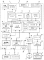
[1.ゲームシステムの全体構成]
以下、図面を参照して、本発明の一実施形態に係るゲームシステム1について説明する。図1は、ゲームシステム1の外観図である。図1において、ゲームシステム1は、テレビジョン受像器等に代表される据置型のディスプレイ装置(以下、「モニタ」と記載する)2、据置型のゲーム装置3、光ディスク4、コントローラ5、マーカ装置6、および、端末装置7を含む。ゲームシステム1は、コントローラ5および/または端末装置7を用いたゲーム操作に基づいてゲーム装置3においてゲーム処理を実行し、ゲーム処理によって得られるゲーム画像をモニタ2および/または端末装置7に表示するものである。
[1. Overall configuration of game system]
Hereinafter, a
ゲーム装置3には、当該ゲーム装置3に対して交換可能に用いられる情報記憶媒体の一例である光ディスク4が脱着可能に挿入される。光ディスク4には、ゲーム装置3において実行されるための情報処理プログラム(典型的にはゲームプログラム)が記憶されている。ゲーム装置3の前面には光ディスク4の挿入口が設けられている。ゲーム装置3は、挿入口に挿入された光ディスク4に記憶されている情報処理プログラムを読み出して実行することによってゲーム処理を実行する。 An optical disk 4 that is an example of an information storage medium that can be used interchangeably with the game apparatus 3 is detachably inserted into the game apparatus 3. The optical disc 4 stores an information processing program (typically a game program) to be executed in the game apparatus 3. An insertion slot for the optical disk 4 is provided on the front surface of the game apparatus 3. The game apparatus 3 executes the game process by reading and executing the information processing program stored in the optical disc 4 inserted into the insertion slot.
ゲーム装置3には、モニタ2が接続コードを介して接続される。モニタ2は、ゲーム装置3において実行されるゲーム処理によって得られるゲーム画像を表示する。モニタ2はスピーカ2a(図2)を有しており、スピーカ2aは、上記ゲーム処理の結果得られるゲーム音声を出力する。なお、他の実施形態においては、ゲーム装置3と据置型の表示装置とは一体となっていてもよい。また、ゲーム装置3とモニタ2との通信は無線通信であってもよい。
A
モニタ2の画面の周辺(図1では画面の上側)には、マーカ装置6が設置される。詳細は後述するが、ユーザ(プレイヤ)はコントローラ5を動かすゲーム操作を行うことができ、マーカ装置6は、コントローラ5の動きや位置や姿勢等をゲーム装置3が算出するために用いられる。マーカ装置6は、その両端に2つのマーカ6Rおよび6Lを備えている。マーカ6R(マーカ6Lも同様)は、具体的には1以上の赤外LED(Light Emitting Diode)であり、モニタ2の前方に向かって赤外光を出力する。マーカ装置6はゲーム装置3に接続されており、ゲーム装置3はマーカ装置6が備える各赤外LEDの点灯を制御することが可能である。なお、マーカ装置6は可搬型であり、ユーザはマーカ装置6を自由な位置に設置することができる。図1ではマーカ装置6がモニタ2の上に設置された態様を表しているが、マーカ装置6を設置する位置および向きは任意である。
A
コントローラ5は、自機に対して行われた操作の内容を表す操作データをゲーム装置3に与えるものである。コントローラ5とゲーム装置3とは無線通信によって通信可能である。本実施形態では、コントローラ5とゲーム装置3との間の無線通信には例えばBluetooth(ブルートゥース)(登録商標)の技術が用いられる。なお、他の実施形態においてはコントローラ5とゲーム装置3とは有線で接続されてもよい。また、本実施形態では、ゲームシステム1に含まれるコントローラ5は1つとするが、ゲーム装置3は複数のコントローラと通信可能であり、所定台数のコントローラを同時に使用することによって複数人でゲームをプレイすることが可能である。コントローラ5の詳細な構成については後述する。
The
端末装置7は、ユーザが把持可能な程度の大きさであり、ユーザは端末装置7を手に持って動かしたり、あるいは、端末装置7を自由な位置に配置したりして使用することが可能である。詳細な構成は後述するが、端末装置7は、表示手段であるLCD(Liquid Crystal Display:液晶表示装置)51、および、入力手段(後述するタッチパネル52やジャイロセンサ64等)を備える。端末装置7とゲーム装置3とは無線(有線であってもよい)によって通信可能である。端末装置7は、ゲーム装置3で生成された画像(例えばゲーム画像)のデータをゲーム装置3から受信し、画像をLCD51に表示する。なお、本実施形態では表示装置としてLCDを用いているが、端末装置7は、例えばEL(Electro Luminescence:電界発光)を利用した表示装置等、他の任意の表示装置を有していてもよい。また、端末装置7は、自機に対して行われた操作の内容を表す操作データをゲーム装置3に送信する。
The
[2.ゲーム装置3の内部構成]
次に、図2を参照して、ゲーム装置3の内部構成について説明する。図2は、ゲーム装置3の内部構成を示すブロック図である。ゲーム装置3は、CPU(Central Processing Unit)10、システムLSI11、外部メインメモリ12、ROM/RTC13、ディスクドライブ14、およびAV−IC15等を有する。
[2. Internal configuration of game device 3]
Next, the internal configuration of the game apparatus 3 will be described with reference to FIG. FIG. 2 is a block diagram showing an internal configuration of the game apparatus 3. The game apparatus 3 includes a CPU (Central Processing Unit) 10, a
CPU10は、光ディスク4に記憶されたゲームプログラムを実行することによってゲーム処理を実行するものであり、ゲームプロセッサとして機能する。CPU10は、システムLSI11に接続される。システムLSI11には、CPU10の他、外部メインメモリ12、ROM/RTC13、ディスクドライブ14およびAV−IC15が接続される。システムLSI11は、それに接続される各構成要素間におけるデータ転送の制御、表示すべき画像の生成、外部装置からのデータの取得等の処理を行う。なお、システムLSI11の内部構成については後述する。揮発性の外部メインメモリ12は、光ディスク4から読み出されたゲームプログラムや、フラッシュメモリ17から読み出されたゲームプログラム等のプログラムを記憶したり、各種データを記憶したりするものであり、CPU10のワーク領域やバッファ領域として用いられる。ROM/RTC13は、ゲーム装置3の起動用のプログラムが組み込まれるROM(いわゆるブートROM)と、時間をカウントするクロック回路(RTC:Real Time Clock)とを有する。ディスクドライブ14は、光ディスク4からプログラムデータやテクスチャデータ等を読み出し、後述する内部メインメモリ11eまたは外部メインメモリ12に読み出したデータを書き込む。
The
システムLSI11には、入出力プロセッサ(I/Oプロセッサ)11a、GPU(Graphics Processor Unit)11b、DSP(Digital Signal Processor)11c、VRAM(Video RAM)11d、および内部メインメモリ11eが設けられる。図示は省略するが、これらの構成要素11a〜11eは内部バスによって互いに接続される。
The
GPU11bは、描画手段の一部を形成し、CPU10からのグラフィクスコマンド(作画命令)に従って画像を生成する。VRAM11dは、GPU11bがグラフィクスコマンドを実行するために必要なデータ(ポリゴンデータやテクスチャデータ等のデータ)を記憶する。画像が生成される際には、GPU11bは、VRAM11dに記憶されたデータを用いて画像データを作成する。なお、ゲーム装置3は、モニタ2に表示する画像と、端末装置7に表示する画像との両方を生成する。以下では、モニタ2に表示される画像を「モニタ用画像」と呼び、端末装置7に表示される画像を「端末用画像」と呼ぶことがある。
The
DSP11cは、オーディオプロセッサとして機能し、内部メインメモリ11eや外部メインメモリ12に記憶されるサウンドデータや音波形(音色)データを用いて、音声データを生成する。なお、本実施形態においては、ゲーム音声についてもゲーム画像と同様、モニタ2のスピーカから出力するゲーム音声と、端末装置7のスピーカから出力するゲーム音声との両方が生成される。以下では、モニタ2から出力される音声を「モニタ用音声」と呼び、端末装置7から出力される音声を「端末用音声」と呼ぶことがある。
The DSP 11c functions as an audio processor, and generates sound data using sound data and sound waveform (tone color) data stored in the internal
上記のようにゲーム装置3において生成される画像および音声のうちで、モニタ2において出力される画像および音声のデータは、AV−IC15によって読み出される。AV−IC15は、読み出した画像データをAVコネクタ16を介してモニタ2に出力するとともに、読み出した音声データを、モニタ2に内蔵されるスピーカ2aに出力する。これによって、モニタ2に画像が表示されるとともにスピーカ2aから音が出力される。なお、ゲーム装置3とモニタ2との接続は、どのような方式で行われてもよいが、ゲーム装置3は、モニタ2を制御する制御指令を有線または無線でモニタ2へ送信するようにしてもよい。例えばHDMI(High−Definition Multimedia Interface)規格に則ったHDMIケーブルが用いられてもよい。HDMI規格では、CEC(Consumer Electronics Control)と呼ばれる機能によって、接続相手の機器を制御することが可能である。したがって、HDMIケーブルが用いられる場合のように、ゲーム装置3がモニタ2に対する制御が可能である場合には、ゲーム装置3は、適宜のタイミングでモニタ2の電源をオンにしたり、モニタ2の入力を切り替えたりすることができる。
Of the images and sounds generated in the game apparatus 3 as described above, the image and sound data output on the
また、ゲーム装置3において生成される画像および音声のうちで、端末装置7において出力される画像および音声のデータは、入出力プロセッサ11a等によって端末装置7へ送信される。入出力プロセッサ11a等による端末装置7へのデータの送信については後述する。
Of the images and sounds generated by the game apparatus 3, the image and sound data output from the
入出力プロセッサ11aは、それに接続される構成要素との間でデータの送受信を実行したり、外部装置からのデータのダウンロードを実行したりする。入出力プロセッサ11aは、フラッシュメモリ17、ネットワーク通信モジュール18、コントローラ通信モジュール19、拡張コネクタ20、メモリカード用コネクタ21、コーデックLSI27に接続される。また、ネットワーク通信モジュール18にはアンテナ22が接続される。コントローラ通信モジュール19にはアンテナ23が接続される。コーデックLSI27は端末通信モジュール28に接続され、端末通信モジュール28にはアンテナ29が接続される。
The input / output processor 11a performs transmission / reception of data to / from components connected to the input / output processor 11a and downloads data from an external device. The input / output processor 11a is connected to the
ゲーム装置3は、インターネット等のネットワークに接続して外部の情報処理装置(例えば他のゲーム装置や、各種サーバ、コンピュータ等)と通信を行うことが可能である。すなわち、入出力プロセッサ11aは、ネットワーク通信モジュール18およびアンテナ22を介してインターネット等のネットワークに接続可能であり、ネットワークに接続される他の装置と通信を行うことができる。入出力プロセッサ11aは、定期的にフラッシュメモリ17にアクセスし、ネットワークへ送信する必要があるデータの有無を検出し、当該データが有る場合には、ネットワーク通信モジュール18およびアンテナ22を介してネットワークに送信する。また、入出力プロセッサ11aは、外部情報処理装置から送信されてくるデータやダウンロードサーバからダウンロードしたデータを、ネットワーク、アンテナ22およびネットワーク通信モジュール18を介して受信し、受信したデータをフラッシュメモリ17に記憶する。CPU10はゲームプログラムを実行することにより、フラッシュメモリ17に記憶されたデータを読み出してゲームプログラムで利用する。フラッシュメモリ17には、ゲーム装置3と外部情報処理装置との間で送受信されるデータの他、ゲーム装置3を利用してプレイしたゲームのセーブデータ(ゲームの結果データまたは途中データ)が記憶されてもよい。また、フラッシュメモリ17にはゲームプログラムが記憶されてもよい。
The game apparatus 3 can connect to a network such as the Internet and communicate with an external information processing apparatus (for example, another game apparatus, various servers, a computer, or the like). In other words, the input / output processor 11a can be connected to a network such as the Internet via the
また、ゲーム装置3は、コントローラ5からの操作データを受信することが可能である。すなわち、入出力プロセッサ11aは、コントローラ5から送信される操作データをアンテナ23およびコントローラ通信モジュール19を介して受信し、内部メインメモリ11eまたは外部メインメモリ12のバッファ領域に記憶(一時記憶)する。
The game apparatus 3 can receive operation data from the
また、ゲーム装置3は、端末装置7との間で画像や音声等のデータを送受信することが可能である。入出力プロセッサ11aは、端末装置7へゲーム画像(端末用ゲーム画像)を送信する場合、GPU11bが生成したゲーム画像のデータをコーデックLSI27へ出力する。コーデックLSI27は、入出力プロセッサ11aからの画像データに対して所定の圧縮処理を行う。端末通信モジュール28は、端末装置7との間で無線通信を行う。したがって、コーデックLSI27によって圧縮された画像データは、端末通信モジュール28によってアンテナ29を介して端末装置7へ送信される。なお、本実施形態では、ゲーム装置3から端末装置7へ送信される画像データはゲームに用いるものであり、ゲームにおいては表示される画像に遅延が生じるとゲームの操作性に悪影響が出る。そのため、ゲーム装置3から端末装置7への画像データの送信に関しては、できるだけ遅延が生じないようにすることが好ましい。したがって、本実施形態では、コーデックLSI27は、例えばH.264規格といった高効率の圧縮技術を用いて画像データを圧縮する。なお、それ以外の圧縮技術を用いてもよいし、通信速度が十分である場合には無圧縮で画像データを送信する構成であってもよい。また、端末通信モジュール28は、例えばWi−Fiの認証を受けた通信モジュールであり、例えばIEEE802.11n規格で採用されるMIMO(Multiple Input Multiple Output)の技術を用いて端末装置7との間の無線通信を高速に行うようにしてもよいし、他の通信方式を用いてもよい。
Further, the game apparatus 3 can transmit and receive data such as images and sounds to and from the
また、ゲーム装置3は、画像データの他、音声データを端末装置7へ送信する。すなわち、入出力プロセッサ11aは、DSP11cが生成した音声データを、コーデックLSI27を介して端末通信モジュール28へ出力する。コーデックLSI27は、音声データに対しても画像データと同様に圧縮処理を行う。音声データに対する圧縮の方式は、どのような方式であってもよいが、圧縮率が高く、音声の劣化が少ない方式が好ましい。また、他の実施形態においては、音声データは圧縮されずに送信されてもよい。端末通信モジュール28は、圧縮された画像データおよび音声データを、アンテナ29を介して端末装置7へ送信する。
In addition to the image data, the game apparatus 3 transmits audio data to the
さらに、ゲーム装置3は、上記画像データおよび音声データの他に、必要に応じて各種の制御データを端末装置7へ送信する。制御データは、端末装置7が備える構成要素に対する制御指示を表すデータであり、例えばマーカ部(図10に示すマーカ部55)の点灯を制御する指示や、カメラ(図10に示すカメラ56)の撮像を制御する指示等を表す。入出力プロセッサ11aは、CPU10の指示に応じて制御データを端末装置7へ送信する。なお、この制御データに関して、本実施形態ではコーデックLSI27はデータの圧縮処理を行わないが、他の実施形態においては圧縮処理を行うようにしてもよい。なお、ゲーム装置3から端末装置7へ送信される上述のデータは、必要に応じて暗号化がされていてもよいし、されていなくともよい。
Further, the game apparatus 3 transmits various control data to the
また、ゲーム装置3は、端末装置7から各種データを受信可能である。詳細は後述するが、本実施形態では、端末装置7は、操作データ、画像データ、および音声データを送信する。端末装置7から送信される各データはアンテナ29を介して端末通信モジュール28によって受信される。ここで、端末装置7からの画像データおよび音声データは、ゲーム装置3から端末装置7への画像データおよび音声データと同様の圧縮処理が施されている。したがって、これら画像データおよび音声データについては、端末通信モジュール28からコーデックLSI27に送られ、コーデックLSI27によって伸張処理が施されて入出力プロセッサ11aに出力される。一方、端末装置7からの操作データに関しては、画像や音声に比べてデータ量が少ないので、圧縮処理が施されていなくともよい。また、必要に応じて暗号化がされていてもよいし、されていなくともよい。したがって、操作データは、端末通信モジュール28で受信された後、コーデックLSI27を介して入出力プロセッサ11aに出力される。入出力プロセッサ11aは、端末装置7から受信したデータを、内部メインメモリ11eまたは外部メインメモリ12のバッファ領域に記憶(一時記憶)する。
The game apparatus 3 can receive various data from the
また、ゲーム装置3は、他の機器や外部記憶媒体に接続することが可能である。すなわち、入出力プロセッサ11aには、拡張コネクタ20およびメモリカード用コネクタ21が接続される。拡張コネクタ20は、USBやSCSIのようなインターフェースのためのコネクタである。拡張コネクタ20に対しては、外部記憶媒体のようなメディアを接続したり、他のコントローラ等の周辺機器を接続したり、有線の通信用コネクタを接続することによってネットワーク通信モジュール18に替えてネットワークとの通信を行ったりすることができる。メモリカード用コネクタ21は、メモリカードのような外部記憶媒体を接続するためのコネクタである。例えば、入出力プロセッサ11aは、拡張コネクタ20やメモリカード用コネクタ21を介して外部記憶媒体にアクセスし、外部記憶媒体にデータを保存したり、外部記憶媒体からデータを読み出したりすることができる。
Further, the game apparatus 3 can be connected to another device or an external storage medium. That is, the
ゲーム装置3には、電源ボタン24、リセットボタン25、およびイジェクトボタン26が設けられる。電源ボタン24およびリセットボタン25は、システムLSI11に接続される。電源ボタン24がオンされると、図示しないACアダプタによって外部の電源からゲーム装置3の各構成要素に対して電力が供給される。リセットボタン25が押されると、システムLSI11は、ゲーム装置3の起動プログラムを再起動する。イジェクトボタン26は、ディスクドライブ14に接続される。イジェクトボタン26が押されると、ディスクドライブ14から光ディスク4が排出される。
The game apparatus 3 is provided with a
なお、他の実施形態においては、ゲーム装置3が備える各構成要素のうちでいくつかの構成要素は、ゲーム装置3とは別体の拡張機器として構成されてもよい。このとき、拡張機器は、例えば上記拡張コネクタ20を介してゲーム装置3と接続されるようにしてもよい。具体的には、拡張機器は、例えば上記コーデックLSI27、端末通信モジュール28およびアンテナ29の各構成要素を備えており、拡張コネクタ20に対して着脱可能であってもよい。これによれば、上記各構成要素を備えていないゲーム装置に対して上記拡張機器を接続することによって、当該ゲーム装置を端末装置7と通信可能な構成とすることができる。
In other embodiments, some of the components included in the game apparatus 3 may be configured as expansion devices that are separate from the game apparatus 3. At this time, the expansion device may be connected to the game apparatus 3 via the
[3.コントローラ5の構成]
次に、図3〜図7を参照して、コントローラ5について説明する。図3は、コントローラ5の外観構成を示す斜視図である。図4は、コントローラ5の外観構成を示す斜視図である。図3は、コントローラ5の上側後方から見た斜視図であり、図4は、コントローラ5を下側前方から見た斜視図である。
[3. Configuration of controller 5]
Next, the
図3および図4において、コントローラ5は、例えばプラスチック成型によって形成されたハウジング31を有している。ハウジング31は、その前後方向(図3に示すZ軸方向)を長手方向とした略直方体形状を有しており、全体として大人や子供の片手で把持可能な大きさである。ユーザは、コントローラ5に設けられたボタンを押下すること、および、コントローラ5自体を動かしてその位置や姿勢(傾き)を変えることによってゲーム操作を行うことができる。
3 and 4, the
ハウジング31には、複数の操作ボタンが設けられる。図3に示すように、ハウジング31の上面には、十字ボタン32a、1番ボタン32b、2番ボタン32c、Aボタン32d、マイナスボタン32e、ホームボタン32f、プラスボタン32g、および電源ボタン32hが設けられる。本明細書では、これらのボタン32a〜32hが設けられるハウジング31の上面を「ボタン面」と呼ぶことがある。一方、図4に示すように、ハウジング31の下面には凹部が形成されており、当該凹部の後面側傾斜面にはBボタン32iが設けられる。これらの各操作ボタン32a〜32iには、ゲーム装置3が実行する情報処理プログラムに応じた機能が適宜割り当てられる。また、電源ボタン32hは遠隔からゲーム装置3本体の電源をオン/オフするためのものである。ホームボタン32fおよび電源ボタン32hは、その上面がハウジング31の上面に埋没している。これによって、ユーザがホームボタン32fまたは電源ボタン32hを誤って押下することを防止することができる。
The
ハウジング31の後面にはコネクタ33が設けられている。コネクタ33は、コントローラ5に他の機器(例えば、他のセンサユニットやコントローラ)を接続するために利用される。また、ハウジング31の後面におけるコネクタ33の両側には、上記他の機器が容易に離脱することを防止するために係止穴33aが設けられている。
A
ハウジング31上面の後方には複数(図3では4つ)のLED34a〜34dが設けられる。ここで、コントローラ5には、他のコントローラと区別するためにコントローラ種別(番号)が付与される。各LED34a〜34dは、コントローラ5に現在設定されている上記コントローラ種別をユーザに通知したり、コントローラ5の電池残量をユーザに通知したりする等の目的で用いられる。具体的には、コントローラ5を用いてゲーム操作が行われる際、上記コントローラ種別に応じて複数のLED34a〜34dのいずれか1つが点灯する。
A plurality (four in FIG. 3) of
また、コントローラ5は撮像情報演算部35(図6)を有しており、図4に示すように、ハウジング31前面には撮像情報演算部35の光入射面35aが設けられる。光入射面35aは、マーカ6Rおよび6Lからの赤外光を少なくとも透過する材質で構成される。
Further, the
ハウジング31上面における1番ボタン32bとホームボタン32fとの間には、コントローラ5に内蔵されるスピーカ47(図5)からの音を外部に放出するための音抜き孔31aが形成されている。
A
次に、図5および図6を参照して、コントローラ5の内部構造について説明する。図5および図6は、コントローラ5の内部構造を示す図である。なお、図5は、コントローラ5の上筐体(ハウジング31の一部)を外した状態を示す斜視図である。図6は、コントローラ5の下筐体(ハウジング31の一部)を外した状態を示す斜視図である。図6に示す斜視図は、図5に示す基板30を裏面から見た斜視図となっている。
Next, the internal structure of the
図5において、ハウジング31の内部には基板30が固設されており、当該基板30の上主面上に各操作ボタン32a〜32h、各LED34a〜34d、加速度センサ37、アンテナ45、およびスピーカ47等が設けられる。これらは、基板30等に形成された配線(図示せず)によってマイクロコンピュータ(Micro Computer:マイコン)42(図6参照)に接続される。本実施形態では、加速度センサ37は、X軸方向に関してコントローラ5の中心からずれた位置に配置されている。これによって、コントローラ5をZ軸回りに回転させたときのコントローラ5の動きが算出しやすくなる。また、加速度センサ37は、長手方向(Z軸方向)に関してコントローラ5の中心よりも前方に配置されている。また、無線モジュール44(図6)およびアンテナ45によって、コントローラ5がワイヤレスコントローラとして機能する。
In FIG. 5, a
一方、図6において、基板30の下主面上の前端縁に撮像情報演算部35が設けられる。撮像情報演算部35は、コントローラ5の前方から順に赤外線フィルタ38、レンズ39、撮像素子40、および画像処理回路41を備えている。これらの部材38〜41はそれぞれ基板30の下主面に取り付けられる。
On the other hand, in FIG. 6, an imaging
さらに、基板30の下主面上には、上記マイコン42およびバイブレータ46が設けられている。バイブレータ46は、例えば振動モータやソレノイドであり、基板30等に形成された配線によってマイコン42と接続される。マイコン42の指示によりバイブレータ46が作動することによってコントローラ5に振動が発生する。これによって、コントローラ5を把持しているユーザの手にその振動が伝達される、いわゆる振動対応ゲームを実現することができる。本実施形態では、バイブレータ46は、ハウジング31のやや前方寄りに配置される。つまり、バイブレータ46がコントローラ5の中心よりも端側に配置することによって、バイブレータ46の振動によりコントローラ5全体を大きく振動させることができる。また、コネクタ33は、基板30の下主面上の後端縁に取り付けられる。なお、図5および図6に示す他、コントローラ5は、マイコン42の基本クロックを生成する水晶振動子、スピーカ47に音声信号を出力するアンプ等を備えている。
Further, the
なお、図3〜図6に示したコントローラ5の形状や、各操作ボタンの形状、加速度センサやバイブレータの数および設置位置等は単なる一例に過ぎず、他の形状、数、および設置位置であってもよい。また、本実施形態では、撮像手段による撮像方向はZ軸正方向であるが、撮像方向はいずれの方向であってもよい。すなわち、コントローラ5における撮像情報演算部35の位置(撮像情報演算部35の光入射面35a)は、ハウジング31の前面でなくてもよく、ハウジング31の外部から光を取り入れることができれば他の面に設けられてもかまわない。
The shape of the
図7は、コントローラ5の構成を示すブロック図である。コントローラ5は、操作部32(各操作ボタン32a〜32i)、撮像情報演算部35、通信部36、加速度センサ37、およびジャイロセンサ48を備えている。コントローラ5は、自機に対して行われた操作内容を表すデータを操作データとしてゲーム装置3へ送信するものである。なお、以下では、コントローラ5が送信する操作データを「コントローラ操作データ」と呼び、端末装置7が送信する操作データを「端末操作データ」と呼ぶことがある。
FIG. 7 is a block diagram showing the configuration of the
操作部32は、上述した各操作ボタン32a〜32iを含み、各操作ボタン32a〜32iに対する入力状態(各操作ボタン32a〜32iが押下されたか否か)を表す操作ボタンデータを通信部36のマイコン42へ出力する。
The
撮像情報演算部35は、撮像手段が撮像した画像データを解析してその中で輝度が高い領域を判別してその領域の重心位置やサイズなどを算出するためのシステムである。撮像情報演算部35は、例えば最大200フレーム/秒程度のサンプリング周期を有するので、比較的高速なコントローラ5の動きでも追跡して解析することができる。
The imaging
撮像情報演算部35は、赤外線フィルタ38、レンズ39、撮像素子40、および画像処理回路41を含んでいる。赤外線フィルタ38は、コントローラ5の前方から入射する光から赤外線のみを通過させる。レンズ39は、赤外線フィルタ38を透過した赤外線を集光して撮像素子40へ入射させる。撮像素子40は、例えばCMOSセンサやあるいはCCDセンサのような固体撮像素子であり、レンズ39が集光した赤外線を受光して画像信号を出力する。ここで、撮像対象となる端末装置7のマーカ部55およびマーカ装置6は、赤外光を出力するマーカで構成される。したがって、赤外線フィルタ38を設けることによって、撮像素子40は、赤外線フィルタ38を通過した赤外線だけを受光して画像データを生成するので、撮像対象(マーカ部55および/またはマーカ装置6)の画像をより正確に撮像することができる。以下では、撮像素子40によって撮像された画像を撮像画像と呼ぶ。撮像素子40によって生成された画像データは、画像処理回路41で処理される。画像処理回路41は、撮像画像内における撮像対象の位置を算出する。画像処理回路41は、算出された位置を示す座標を通信部36のマイコン42へ出力する。この座標のデータは、マイコン42によって操作データとしてゲーム装置3に送信される。以下では、上記座標を「マーカ座標」と呼ぶ。マーカ座標はコントローラ5自体の向き(傾斜角度)や位置に対応して変化するので、ゲーム装置3はこのマーカ座標を用いてコントローラ5の向きや位置を算出することができる。
The imaging
なお、他の実施形態においては、コントローラ5は画像処理回路41を備えていない構成であってもよく、撮像画像自体がコントローラ5からゲーム装置3へ送信されてもよい。このとき、ゲーム装置3は、画像処理回路41と同様の機能を有する回路あるいはプログラムを有しており、上記マーカ座標を算出するようにしてもよい。
In other embodiments, the
加速度センサ37は、コントローラ5の加速度(重力加速度を含む)を検出する、すなわち、コントローラ5に加わる力(重力を含む)を検出する。加速度センサ37は、当該加速度センサ37の検出部に加わっている加速度のうち、センシング軸方向に沿った直線方向の加速度(直線加速度)の値を検出する。例えば、2軸以上の多軸加速度センサの場合には、加速度センサの検出部に加わっている加速度として、各軸に沿った成分の加速度をそれぞれ検出する。なお、加速度センサ37は、例えば静電容量式のMEMS(Micro Electro Mechanical System)型加速度センサであるとするが、他の方式の加速度センサを用いるようにしてもよい。
The
本実施形態では、加速度センサ37は、コントローラ5を基準とした上下方向(図3に示すY軸方向)、左右方向(図3に示すX軸方向)および前後方向(図3に示すZ軸方向)の3軸方向に関してそれぞれ直線加速度を検出する。加速度センサ37は、各軸に沿った直線方向に関する加速度を検出するものであるため、加速度センサ37からの出力は3軸それぞれの直線加速度の値を表すものとなる。すなわち、検出された加速度は、コントローラ5を基準に設定されるXYZ座標系(コントローラ座標系)における3次元のベクトルとして表される。
In the present embodiment, the
加速度センサ37が検出した加速度を表すデータ(加速度データ)は、通信部36へ出力される。なお、加速度センサ37が検出した加速度は、コントローラ5自体の向き(傾斜角度)や動きに対応して変化するので、ゲーム装置3は取得された加速度データを用いてコントローラ5の向きや動きを算出することができる。本実施形態では、ゲーム装置3は、取得された加速度データに基づいてコントローラ5の姿勢や傾斜角度等を算出する。
Data representing the acceleration detected by the acceleration sensor 37 (acceleration data) is output to the
なお、加速度センサ37(後述する加速度センサ63についても同様)から出力される加速度の信号に基づいて、ゲーム装置3のプロセッサ(例えばCPU10)またはコントローラ5のプロセッサ(例えばマイコン42)等のコンピュータが処理を行うことによって、コントローラ5に関するさらなる情報を推測または算出(判定)することができることは、当業者であれば本明細書の説明から容易に理解できるであろう。例えば、加速度センサ37を搭載するコントローラ5が静止状態であることを前提としてコンピュータ側の処理が実行される場合(すなわち、加速度センサによって検出される加速度が重力加速度のみであるとして処理が実行される場合)、コントローラ5が現実に静止状態であれば、検出された加速度に基づいてコントローラ5の姿勢が重力方向に対して傾いているか否かまたはどの程度傾いているかを知ることができる。具体的には、加速度センサ37の検出軸が鉛直下方向を向いている状態を基準としたとき、1G(重力加速度)がかかっているか否かによって、コントローラ5が基準に対して傾いているか否かを知ることができるし、その大きさによって基準に対してどの程度傾いているかも知ることができる。また、多軸の加速度センサ37の場合には、さらに各軸の加速度の信号に対して処理を施すことによって、重力方向に対してコントローラ5がどの程度傾いているかをより詳細に知ることができる。この場合において、プロセッサは、加速度センサ37からの出力に基づいてコントローラ5の傾斜角度を算出してもよいし、当該傾斜角度を算出せずに、コントローラ5の傾斜方向を算出するようにしてもよい。このように、加速度センサ37をプロセッサと組み合わせて用いることによって、コントローラ5の傾斜角度または姿勢を判定することができる。
A computer such as a processor (for example, CPU 10) of the game apparatus 3 or a processor (for example, the microcomputer 42) of the
一方、コントローラ5が動的な状態(コントローラ5が動かされている状態)であることを前提とする場合には、加速度センサ37は重力加速度に加えてコントローラ5の動きに応じた加速度を検出するので、検出された加速度から重力加速度の成分を所定の処理により除去することによってコントローラ5の動き方向を知ることができる。また、コントローラ5が動的な状態であることを前提とする場合であっても、検出された加速度から、加速度センサの動きに応じた加速度の成分を所定の処理により除去することによって、重力方向に対するコントローラ5の傾きを知ることが可能である。なお、他の実施例では、加速度センサ37は、内蔵の加速度検出手段で検出された加速度信号をマイコン42に出力する前に当該加速度信号に対して所定の処理を行うための、組込み式の処理装置または他の種類の専用の処理装置を備えていてもよい。組込み式または専用の処理装置は、例えば、加速度センサ37が静的な加速度(例えば、重力加速度)を検出するために用いられる場合、加速度信号を傾斜角(あるいは、他の好ましいパラメータ)に変換するものであってもよい。
On the other hand, when it is assumed that the
ジャイロセンサ48は、3軸(本実施形態では、XYZ軸)回りの角速度を検出する。本明細書では、コントローラ5の撮像方向(Z軸正方向)を基準として、X軸回りの回転方向をピッチ方向、Y軸回りの回転方向をヨー方向、Z軸回りの回転方向をロール方向と呼ぶ。ジャイロセンサ48は、3軸回りの角速度を検出することができればよく、用いるジャイロセンサの数および組み合わせはどのようなものであってもよい。例えば、ジャイロセンサ48は、3軸ジャイロセンサであってもよいし、2軸ジャイロセンサと1軸ジャイロセンサとを組み合わせて3軸周りの角速度を検出するものであってもよい。ジャイロセンサ48で検出された角速度を表すデータは、通信部36へ出力される。また、ジャイロセンサ48は1軸または2軸回りの角速度を検出するものであってもよい。
The
通信部36は、マイコン42、メモリ43、無線モジュール44、およびアンテナ45を含んでいる。マイコン42は、処理を行う際にメモリ43を記憶領域として用いながら、マイコン42が取得したデータをゲーム装置3へ無線送信する無線モジュール44を制御する。
The
操作部32、撮像情報演算部35、加速度センサ37、およびジャイロセンサ48からマイコン42へ出力されたデータは、一時的にメモリ43に格納される。これらのデータは、操作データ(コントローラ操作データ)としてゲーム装置3へ送信される。すなわち、マイコン42は、ゲーム装置3のコントローラ通信モジュール19への送信タイミングが到来すると、メモリ43に格納されている操作データを無線モジュール44へ出力する。無線モジュール44は、例えばBluetooth(ブルートゥース)(登録商標)の技術を用いて、所定周波数の搬送波を操作データで変調し、その微弱電波信号をアンテナ45から放射する。つまり、操作データは、無線モジュール44で微弱電波信号に変調されてコントローラ5から送信される。微弱電波信号はゲーム装置3側のコントローラ通信モジュール19で受信される。受信された微弱電波信号について復調や復号を行うことによって、ゲーム装置3は操作データを取得することができる。そして、ゲーム装置3のCPU10は、コントローラ5から取得した操作データを用いてゲーム処理を行う。なお、通信部36からコントローラ通信モジュール19への無線送信は所定の周期毎に逐次行われるが、ゲームの処理は1/60秒を単位として(1フレーム時間として)行われることが一般的であるので、この時間以下の周期で送信を行うことが好ましい。コントローラ5の通信部36は、例えば1/200秒に1回の割合で操作データをゲーム装置3のコントローラ通信モジュール19へ出力する。
Data output from the
以上のように、コントローラ5は、自機に対する操作を表す操作データとして、マーカ座標データ、加速度データ、角速度データ、および操作ボタンデータを送信可能である。また、ゲーム装置3は、上記操作データをゲーム入力として用いてゲーム処理を実行する。したがって、上記コントローラ5を用いることによって、ユーザは、各操作ボタンを押下する従来の一般的なゲーム操作に加えて、コントローラ5自体を動かすゲーム操作を行うことができる。例えば、コントローラ5を任意の姿勢に傾ける操作、コントローラ5によって画面上の任意の位置を指示する操作、および、コントローラ5自体を動かす操作等を行うことが可能となる。
As described above, the
また、本実施形態において、コントローラ5は、ゲーム画像を表示する表示手段を有しないが、例えば電池残量を表す画像等を表示するための表示手段を有していてもよい。
In the present embodiment, the
[4.端末装置7の構成]
次に、図8〜図10を参照して、端末装置7の構成について説明する。図8は、端末装置7の外観構成を示す図である。図8における(a)図は端末装置7の正面図であり、(b)図は上面図であり、(c)図は右側面図であり、(d)図は下面図である。また、図9は、ユーザが端末装置7を把持した様子を示す図である。
[4. Configuration of Terminal Device 7]
Next, the configuration of the
図8に示されるように、端末装置7は、大略的には横長の長方形の板状形状であるハウジング50を備える。ハウジング50は、ユーザが把持することができる程度の大きさである。したがって、ユーザは、端末装置7を持って動かしたり、端末装置7の配置位置を変更したりすることができる。
As shown in FIG. 8, the
端末装置7は、ハウジング50の表面にLCD51を有する。LCD51は、ハウジング50の表面の中央付近に設けられる。したがって、ユーザは、図9に示すようにLCD51の両側部分のハウジング50を持つことによって、LCD51の画面を見ながら端末装置を持って動かすことができる。なお、図9ではユーザがLCD51の左右両側の部分のハウジング50を持つことで端末装置7を横持ちで(横に長い向きにして)持つ例を示しているが、端末装置7を縦持ちで(縦に長い向きにして)持つことも可能である。
The
図8の(a)図に示すように、端末装置7は、操作手段として、LCD51の画面上にタッチパネル52を有する。本実施形態では、タッチパネル52は抵抗膜方式のタッチパネルである。ただし、タッチパネルは抵抗膜方式に限らず、例えば静電容量方式等、任意の方式のタッチパネルを用いることができる。また、タッチパネル52はシングルタッチ方式でもよいし、マルチタッチ方式であってもよい。本実施形態では、タッチパネル52として、LCD51の解像度と同解像度(検出精度)のものを利用する。ただし、必ずしもタッチパネル52の解像度とLCD51の解像度が一致している必要はない。タッチパネル52に対する入力は通常タッチペンを用いて行われるが、タッチペンに限らずユーザの指でタッチパネル52に対する入力をすることも可能である。なお、ハウジング50には、タッチパネル52に対する操作を行うために用いられるタッチペンを収納するための収納穴が設けられていてもよい。このように、端末装置7はタッチパネル52を備えるので、ユーザは、端末装置7を動かしながらタッチパネル52を操作することができる。つまりユーザは、LCD51の画面を動かしつつ、その画面に対して直接(タッチパネル52によって)入力を行うことができる。
As illustrated in FIG. 8A, the
図8に示すように、端末装置7は、操作手段として、2つのアナログスティック53Aおよび53Bと、複数のボタン54A〜54Lとを備えている。各アナログスティック53Aおよび53Bは、方向を指示するデバイスである。各アナログスティック53Aおよび53Bは、ユーザの指で操作されるスティック部がハウジング50の表面に対して任意の方向(上下左右および斜め方向の任意の角度)にスライド(または傾倒)することができるように構成されている。また、左アナログスティック53AはLCD51の画面の左側に、右アナログスティック53BはLCD51の画面の右側にそれぞれ設けられる。したがって、ユーザは、左右いずれの手でもアナログスティックを用いて方向を指示する入力を行うことができる。また、図9に示すように、各アナログスティック53Aおよび53Bは、ユーザが端末装置7の左右部分を把持した状態で操作可能な位置に設けられるので、ユーザは、端末装置7を持って動かす場合においても各アナログスティック53Aおよび53Bを容易に操作することができる。
As shown in FIG. 8, the
各ボタン54A〜54Lは、所定の入力を行うための操作手段である。以下に示すように、各ボタン54A〜54Lは、ユーザが端末装置7の左右部分を把持した状態で操作可能な位置に設けられる(図9参照)。したがって、ユーザは、端末装置7を持って動かす場合においてもこれらの操作手段を容易に操作することができる。
Each
図8の(a)図に示すように、ハウジング50の表面には、各操作ボタン54A〜54Lのうち、十字ボタン(方向入力ボタン)54Aと、ボタン54B〜54Hとが設けられる。つまり、これらのボタン54A〜54Gは、ユーザの親指で操作可能な位置に配置されている(図9参照)。
As shown in FIG. 8A, on the surface of the
十字ボタン54Aは、LCD51の左側であって、左アナログスティック53Aの下側に設けられる。つまり、十字ボタン54Aはユーザの左手で操作可能な位置に配置されている。十字ボタン54Aは、十字の形状を有しており、上下左右の方向を指示することが可能なボタンである。また、ボタン54B〜54Dは、LCD51の下側に設けられる。これら3つのボタン54B〜54Dは、左右両方の手で操作可能な位置に配置されている。また、4つのボタン54E〜54Hは、LCD51の右側であって、右アナログスティック53Bの下側に設けられる。つまり、4つのボタン54E〜54Hはユーザの右手で操作可能な位置に配置されている。さらに、4つのボタン54E〜54Hは、(4つのボタン54E〜54Hの中心位置に対して)上下左右の位置関係となるように配置されている。したがって、端末装置7は、ユーザに上下左右の方向を指示させるためのボタンとして4つのボタン54E〜54Hを機能させることも可能である。
The
また、図8の(a)図、(b)図、および(c)図に示すように、第1Lボタン54Iおよび第1Rボタン54Jは、ハウジング50の斜め上部分(左上部分および右上部分)に設けられる。具体的には、第1Lボタン54Iは、板状のハウジング50における上側の側面の左端に設けられ、上側および左側の側面から露出している。また、第1Rボタン54Jは、ハウジング50における上側の側面の右端に設けられ、上側および右側の側面から露出している。このように、第1Lボタン54Iは、ユーザの左手人差し指で操作可能な位置に配置され、第1Rボタン54Jは、ユーザの右手人差し指で操作可能な位置に配置される(図9参照)。
Further, as shown in FIGS. 8A, 8B, and 8C, the first L button 54I and the
また、図8の(b)図および(c)図に示すように、第2Lボタン54Kおよび第2Rボタン54Lは、板状のハウジング50の裏面(すなわちLCD51が設けられる表面の反対側の面)に突起して設けられる足部59Aおよび59Bに配置される。具体的には、第2Lボタン54Kは、ハウジング50の裏面の左側(表面側から見たときの左側)のやや上方に設けられ、第2Rボタン54Lは、ハウジング50の裏面の右側(表面側から見たときの右側)のやや上方に設けられる。換言すれば、第2Lボタン54Kは、表面に設けられる左アナログスティック53Aの概ね反対側の位置に設けられ、第2Rボタン54Lは、表面に設けられる右アナログスティック53Bの概ね反対側の位置に設けられる。このように、第2Lボタン54Kは、ユーザの左手中指で操作可能な位置に配置され、第2Rボタン54Lは、ユーザの右手中指で操作可能な位置に配置される(図9参照)。また、第2Lボタン54Kおよび第2Rボタン54Lは、図8の(c)図に示すように、上記足部59Aおよび59Bの斜め上方を向く面に設けられ、斜め上方を向くボタン面を有する。ユーザが端末装置7を把持した場合には中指は上下方向に動くと考えられるので、ボタン面を上方に向けることで、ユーザは第2Lボタン54Kおよび第2Rボタン54Lを押下しやすくなる。また、ハウジング50の裏面に足部が設けられることにより、ユーザはハウジング50を把持しやすくなり、かつ、足部にボタンが設けられることで、ハウジング50を把持したまま操作しやすくなる。
As shown in FIGS. 8B and 8C, the
なお、図8に示す端末装置7に関しては、第2Lボタン54Kおよび第2Rボタン54Lが裏面に設けられるので、LCD51の画面(ハウジング50の表面)が上を向いた状態で端末装置7を載置させる場合、画面が完全に水平にはならない場合がある。そのため、他の実施形態においては、ハウジング50の裏面に3つ以上の足部が形成されてもよい。これによれば、LCD51の画面が上を向いた状態では足部が床面に接することで床面に載置できるので、画面が水平になるように端末装置7を載置することができる。また、着脱可能な足部を追加することで端末装置7を水平に載置するようにしてもよい。
For the
各ボタン54A〜54Lには、ゲームプログラムに応じた機能が適宜割り当てられる。例えば、十字ボタン54Aおよびボタン54E〜54Hは方向指示操作や選択操作等に用いられてもよいし、各ボタン54B〜54Eは決定操作やキャンセル操作等に用いられてもよい。
Functions corresponding to the game program are appropriately assigned to the
なお、図示しないが、端末装置7は、端末装置7の電源をオン/オフするための電源ボタンを有している。また、端末装置7は、LCD51の画面表示をオン/オフするためのボタンや、ゲーム装置3との接続設定(ペアリング)を行うためのボタンや、スピーカ(図10に示すスピーカ67)の音量を調節するためのボタンを有していてもよい。
Although not shown, the
図8の(a)図に示すように、端末装置7は、マーカ55Aおよびマーカ55Bからなるマーカ部(図10に示すマーカ部55)をハウジング50の表面に備えている。マーカ部55は、LCD51の上側に設けられる。各マーカ55Aおよびマーカ55Bは、マーカ装置6の各マーカ6Rおよび6Lと同様、1以上の赤外LEDで構成される。マーカ部55は、上述のマーカ装置6と同様、コントローラ5の動き等をゲーム装置3が算出するために用いられる。また、ゲーム装置3はマーカ部55が備える各赤外LEDの点灯を制御することが可能である。
As illustrated in FIG. 8A, the
端末装置7は、撮像手段であるカメラ56を備えている。カメラ56は、所定の解像度を有する撮像素子(例えば、CCDイメージセンサやCMOSイメージセンサ等)と、レンズとを含む。図8に示すように、本実施形態では、カメラ56はハウジング50の表面に設けられる。したがって、カメラ56は、端末装置7を持っているユーザの顔を撮像することができ、例えばLCD51を見ながらゲームを行っている時のユーザを撮像することができる。
The
なお、端末装置7は、音声入力手段であるマイク(図10に示すマイク69)を備えている。ハウジング50の表面には、マイクロフォン用孔60が設けられる。マイク69はこのマイクロフォン用孔60の奥のハウジング50内部に設けられる。マイクは、ユーザの音声等、端末装置7の周囲の音を検出する。
The
端末装置7は、音声出力手段であるスピーカ(図10に示すスピーカ67)を備えている。図8の(d)図に示すように、ハウジング50の下側側面にはスピーカ孔57が設けられる。スピーカ67の出力音はこのスピーカ孔57から出力される。本実施形態では、端末装置7は2つのスピーカを備えており、左スピーカおよび右スピーカのそれぞれの位置にスピーカ孔57が設けられる。
The
また、端末装置7は、他の装置を端末装置7に接続するための拡張コネクタ58を備えている。本実施形態においては、図8の(d)図に示すように、拡張コネクタ58は、ハウジング50の下側側面に設けられる。なお、拡張コネクタ58に接続される他の装置はどのようなものであってもよく、例えば、特定のゲームに用いるコントローラ(銃型のコントローラ等)やキーボード等の入力装置であってもよい。他の装置を接続する必要がなければ、拡張コネクタ58は設けられていなくともよい。
Further, the
なお、図8に示した端末装置7に関して、各操作ボタンやハウジング50の形状や、各構成要素の数および設置位置等は単なる一例に過ぎず、他の形状、数、および設置位置であってもよい。
In addition, regarding the
次に、図10を参照して、端末装置7の内部構成について説明する。図10は、端末装置7の内部構成を示すブロック図である。図10に示すように、端末装置7は、図8に示した構成の他、タッチパネルコントローラ61、磁気センサ62、加速度センサ63、ジャイロセンサ64、ユーザインタフェースコントローラ(UIコントローラ)65、コーデックLSI66、スピーカ67、サウンドIC68、マイク69、無線モジュール70、アンテナ71、赤外線通信モジュール72、フラッシュメモリ73、電源IC74、電池75、および、バイブレータ79を備える。これらの電子部品は、電子回路基板上に実装されてハウジング50内に収納される。
Next, the internal configuration of the
UIコントローラ65は、各種の入出力部に対するデータの入出力を制御するための回路である。UIコントローラ65は、タッチパネルコントローラ61、アナログスティック53(アナログスティック53Aおよび53B)、操作ボタン54(各操作ボタン54A〜54L)、マーカ部55、磁気センサ62、加速度センサ63、ジャイロセンサ64、およびバイブレータ79に接続される。また、UIコントローラ65は、コーデックLSI66と拡張コネクタ58に接続される。また、UIコントローラ65には電源IC74が接続され、UIコントローラ65を介して各部に電力が供給される。電源IC74には内蔵の電池75が接続され、電力が供給される。また、電源IC74には、コネクタ等を介して外部電源から電力を取得可能な充電器76またはケーブルを接続することが可能であり、端末装置7は、当該充電器76またはケーブルを用いて外部電源からの電力供給と充電を行うことができる。なお、端末装置7は、図示しない充電機能を有するクレイドルに端末装置7を装着することで充電を行うようにしてもよい。
The
タッチパネルコントローラ61は、タッチパネル52に接続され、タッチパネル52の制御を行う回路である。タッチパネルコントローラ61は、タッチパネル52からの信号に基づいて所定の形式のタッチ位置データを生成してUIコントローラ65へ出力する。タッチ位置データは、タッチパネル52の入力面において入力が行われた位置の座標を表す。なお、タッチパネルコントローラ61は、タッチパネル52からの信号の読み込み、および、タッチ位置データの生成を所定時間に1回の割合で行う。また、UIコントローラ65からタッチパネルコントローラ61へは、タッチパネル52に対する各種の制御指示が出力される。
The
アナログスティック53は、ユーザの指で操作されるスティック部がスライドした(または傾倒した)方向および量を表すスティックデータをUIコントローラ65へ出力する。また、操作ボタン54は、各操作ボタン54A〜54Lに対する入力状況(押下されたか否か)を表す操作ボタンデータをUIコントローラ65へ出力する。
The
磁気センサ62は、磁界の大きさおよび方向を検知することで方位を検出する。検出された方位を示す方位データは、UIコントローラ65へ出力される。また、UIコントローラ65から磁気センサ62へは、磁気センサ62に対する制御指示が出力される。磁気センサ62に関しては、MI(磁気インピーダンス)素子、フラックスゲートセンサ、ホール素子、GMR(巨大磁気抵抗)素子、TMR(トンネル磁気抵抗)素子、あるいはAMR(異方性磁気抵抗)素子等を用いたセンサがあるが、方位を検出することができればどのようなものが用いられてもよい。なお、厳密には、地磁気以外に磁界が発生している場所においては、得られた方位データは方位を示さないことになるが、そのような場合であっても、端末装置7が動いた場合には方位データが変化するため、端末装置7の姿勢の変化を算出することができる。
The magnetic sensor 62 detects the azimuth by detecting the magnitude and direction of the magnetic field. The azimuth data indicating the detected azimuth is output to the
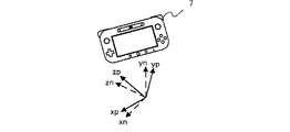
加速度センサ63は、ハウジング50の内部に設けられ、3軸(図8の(a)図に示すxyz軸)方向に沿った直線加速度の大きさを検出する。具体的には、加速度センサ63は、ハウジング50の長辺方向をx軸、ハウジング50の短辺方向をy軸、ハウジング50の表面に対して垂直な方向をz軸として、各軸の直線加速度の大きさを検出する。検出された加速度を表す加速度データはUIコントローラ65へ出力される。また、UIコントローラ65から加速度センサ63へは、加速度センサ63に対する制御指示が出力される。加速度センサ63は、本実施形態では例えば静電容量式のMEMS型加速度センサであるとするが、他の実施形態においては他の方式の加速度センサを用いるようにしてもよい。また、加速度センサ63は1軸または2軸方向を検出する加速度センサであってもよい。
The
ジャイロセンサ64は、ハウジング50の内部に設けられ、上記x軸、y軸およびz軸の3軸周りの角速度を検出する。検出された角速度を表す角速度データは、UIコントローラ65へ出力される。また、UIコントローラ65からジャイロセンサ64へは、ジャイロセンサ64に対する制御指示が出力される。なお、3軸の角速度を検出するために用いられるジャイロセンサの数および組み合わせはどのようなものであってもよく、ジャイロセンサ64はジャイロセンサ48と同様、2軸ジャイロセンサと1軸ジャイロセンサとで構成されてもよい。また、ジャイロセンサ64は1軸または2軸方向を検出するジャイロセンサであってもよい。
The gyro sensor 64 is provided inside the
バイブレータ79は、例えば振動モータやソレノイドであり、UIコントローラ65に接続される。UIコントローラ65の指示によりバイブレータ79が作動することによって端末装置7に振動が発生する。これによって、端末装置7を把持しているユーザの手にその振動が伝達される、いわゆる振動対応ゲームを実現することができる。
The vibrator 79 is a vibration motor or a solenoid, for example, and is connected to the
UIコントローラ65は、上記の各構成要素から受け取ったタッチ位置データ、スティックデータ、操作ボタンデータ、方位データ、加速度データ、および角速度データを含む操作データをコーデックLSI66に出力する。なお、拡張コネクタ58を介して端末装置7に他の装置が接続される場合には、当該他の装置に対する操作を表すデータが上記操作データにさらに含まれていてもよい。
The
コーデックLSI66は、ゲーム装置3へ送信するデータに対する圧縮処理、および、ゲーム装置3から送信されたデータに対する伸張処理を行う回路である。コーデックLSI66には、LCD51、カメラ56、サウンドIC68、無線モジュール70、フラッシュメモリ73、および赤外線通信モジュール72が接続される。また、コーデックLSI66はCPU77と内部メモリ78を含む。端末装置7はゲーム処理自体を行なわない構成であるが、端末装置7の管理や通信のための最小限のプログラムを実行する必要がある。電源投入時にフラッシュメモリ73に格納されたプログラムを内部メモリ78に読み出してCPU77が実行することで、端末装置7が起動する。また、内部メモリ78の一部の領域はLCD51のためのVRAMとして使用される。
The
カメラ56は、ゲーム装置3からの指示に従って画像を撮像し、撮像した画像データをコーデックLSI66へ出力する。また、コーデックLSI66からカメラ56へは、画像の撮像指示等、カメラ56に対する制御指示が出力される。なお、カメラ56は動画の撮影も可能である。すなわち、カメラ56は、繰り返し撮像を行って画像データをコーデックLSI66へ繰り返し出力することも可能である。
The
サウンドIC68は、スピーカ67およびマイク69に接続され、スピーカ67およびマイク69への音声データの入出力を制御する回路である。すなわち、コーデックLSI66から音声データを受け取った場合、サウンドIC68は当該音声データに対してD/A変換を行って得られる音声信号をスピーカ67へ出力し、スピーカ67から音を出力させる。また、マイク69は、端末装置7に伝わる音(ユーザの音声等)を検知して、当該音を示す音声信号をサウンドIC68へ出力する。サウンドIC68は、マイク69からの音声信号に対してA/D変換を行い、所定の形式の音声データをコーデックLSI66へ出力する。
The
赤外線通信モジュール72は、赤外線信号を発光し、他の装置との間で赤外線通信を行う。ここでは、赤外線通信モジュール72は、例えばIrDAの規格に従った赤外線通信を行う機能と、モニタ2を制御するための赤外線信号を出力する機能とを備える。
The
コーデックLSI66は、カメラ56からの画像データと、マイク69からの音声データと、UIコントローラ65からの端末操作データとを無線モジュール70を介してゲーム装置3へ送信する。本実施形態では、コーデックLSI66は、画像データおよび音声データに対して、コーデックLSI27と同様の圧縮処理を行う。上記端末操作データ、ならびに、圧縮された画像データおよび音声データは、送信データとして無線モジュール70に出力される。無線モジュール70にはアンテナ71が接続されており、無線モジュール70はアンテナ71を介してゲーム装置3へ上記送信データを送信する。無線モジュール70は、ゲーム装置3の端末通信モジュール28と同様の機能を有している。すなわち、無線モジュール70は、例えばIEEE802.11nの規格に準拠した方式により、無線LANに接続する機能を有する。送信されるデータは必要に応じて暗号化されていてもよいし、されていなくともよい。
The
以上のように、端末装置7からゲーム装置3へ送信される送信データには、操作データ(端末操作データ)、画像データ、および音声データが含まれる。なお、拡張コネクタ58を介して端末装置7に他の装置が接続される場合には、当該他の装置から受け取ったデータが上記送信データにさらに含まれていてもよい。コーデックLSI66は、赤外線通信モジュール72による赤外線通信によって受信したデータを、必要に応じて上記送信データに含めてゲーム装置3へ送信してもよい。
As described above, the transmission data transmitted from the
また、上述のように、ゲーム装置3から端末装置7へは、圧縮された画像データおよび音声データが送信される。これらのデータはアンテナ71および無線モジュール70を介してコーデックLSI66に受信される。コーデックLSI66は、受信した画像データおよび音声データを伸張する。伸張された画像データはLCD51へ出力され、画像がLCD51に表示される。また、伸張された音声データはサウンドIC68へ出力され、サウンドIC68はスピーカ67から音を出力させる。
Further, as described above, compressed image data and audio data are transmitted from the game apparatus 3 to the
また、ゲーム装置3から受信されるデータに制御データが含まれる場合、コーデックLSI66およびUIコントローラ65は、制御データに従った制御指示を各部に行う。上述のように、制御データは、端末装置7が備える各構成要素(本実施形態では、カメラ56、タッチパネルコントローラ61、マーカ部55、各センサ62〜64、赤外線通信モジュール72、およびバイブレータ79)に対する制御指示を表すデータである。本実施形態では、制御データが表す制御指示としては、上記各構成要素を動作させたり、動作を休止(停止)させたりする指示が考えられる。すなわち、ゲームで使用しない構成要素については電力消費を抑えるために休止させてもよく、その場合、端末装置7からゲーム装置3へ送信される送信データには、休止した構成要素からのデータが含まれないようにする。なお、マーカ部55は赤外LEDであるので、制御は単に電力の供給のON/OFFでよい。
When the control data is included in the data received from the game apparatus 3, the
また、ゲーム装置3は、上記赤外線通信モジュール72の出力を制御することによって、モニタ2の動作を制御することが可能である。すなわち、ゲーム装置3は、モニタ2を制御するための制御指令に対応する赤外線信号を赤外線通信モジュール72に出力させるための指示(上記制御データ)を端末装置7に出力する。この指示に応じて、コーデックLSI66は、上記制御指令に対応する赤外線信号を赤外線通信モジュール72に出力させる。ここで、モニタ2は赤外線信号を受光可能な赤外線受光部を備えている。赤外線通信モジュール72から出力された赤外線信号が赤外線受光部によって受光されることで、モニタ2は当該赤外線信号に応じた動作を行う。なお、ゲーム装置3からの上記指示は、赤外線信号のパターンを示すものであってもよいし、端末装置7が赤外線信号のパターンを記憶している場合には、当該パターンを示す指示であってもよい。
Further, the game apparatus 3 can control the operation of the
以上のように、端末装置7は、タッチパネル52、アナログスティック53、および操作ボタン54といった操作手段を備えるが、他の実施形態においては、これらの操作手段に代えて、または、これらの操作手段とともに、他の操作手段を備える構成であってもよい。
As described above, the
また、端末装置7は、端末装置7の動き(位置や姿勢、あるいは、位置や姿勢の変化を含む)を算出するためのセンサとして、磁気センサ62、加速度センサ63、およびジャイロセンサ64を備えるが、他の実施形態においては、これらのセンサのうち1つまたは2つのみを備える構成であってもよい。また、他の実施形態においては、これらのセンサに代えて、または、これらのセンサとともに、他のセンサを備える構成であってもよい。
Further, the
また、端末装置7は、カメラ56およびマイク69を備える構成であるが、他の実施形態においては、カメラ56およびマイク69を備えていなくてもよく、また、いずれか一方のみを備えていてもよい。
Moreover, although the
また、端末装置7は、端末装置7とコントローラ5との位置関係(コントローラ5から見た端末装置7の位置および/または姿勢等)を算出するための構成としてマーカ部55を備える構成であるが、他の実施形態ではマーカ部55を備えていない構成としてもよい。また、他の実施形態では、端末装置7は、上記位置関係を算出するための構成として他の手段を備えていてもよい。例えば、他の実施形態においては、コントローラ5がマーカ部を備え、端末装置7が撮像素子を備える構成としてもよい。さらにこの場合、マーカ装置6は赤外LEDに代えて、撮像素子を備える構成としてもよい。
Further, the
[5.パノラマ動画の再生]
次に、ゲームシステム1において実行される動画再生の動作について説明する。ゲームシステム1は、内部メモリに記憶されたパノラマ動画を読みだして再生し、端末装置7に表示する。端末装置7には、動画の再生の進行にしたがって、所定時間ごとに、パノラマ動画の各フレームが順次表示されるが、各フレームのパノラマ画像の全体が端末装置7に表示されるのではなく、その一部が表示される。パノラマ画像のうち表示される領域(以下、単に「表示領域」と呼ぶこともある)は、そのときの端末装置7の姿勢に応じて変更される。以下、具体的に説明する。
[5. Play panoramic video]
Next, the moving image playback operation executed in the
パノラマ動画の再生開始を指示すると、端末装置7にはパノラマ動画の先頭フレームのパノラマ画像のうちデフォルトの領域が表示される。このデフォルトの領域は、パノラマ画像のうちパノラマ撮影の基準方向(通常は、撮影機材の進行方向)に対応する領域とするのが好ましく、典型的には、パノラマ画像の中央の領域とするのが好ましい。その後、パノラマ動画の再生が継続するが、端末装置7の姿勢を変化せずに保持する限り、端末装置7には各フレームのパノラマ画像のうちのデフォルトの範囲が表示される。そして、パノラマ動画の再生継続中に端末装置7の姿勢を変更すると、表示領域が変更される。
When the start of playback of the panoramic video is instructed, the
より具体的には、端末装置7を把持した使用者が、端末装置7の画面を自分の方に向けたまま、自分を中心にして端末装置7を上下左右に動かすことにより、表示領域が上下左右に変更される。ここで、使用者が端末装置7の画面を自分の方に向けたまま、端末装置7を自分を中心にして上方向に動かすと、端末装置7の画面は斜め下方向または下方向を向き、使用者は自分より上にある端末装置7の画面を下から見るような位置関係となる。このとき、表示領域は、デフォルト領域よりも、または、動かす前の表示領域よりも、上側の領域となる。また、使用者が端末装置7の画面を自分の方に向けたまま、端末装置7を自分を中心にして下方向に動かすと、端末装置7の画面は斜め上方向または上方向を向き、使用者は自分より下にある端末装置7の画面を上から見るような位置関係になる。このとき、表示領域は、デフォルト領域よりも、または、動かす前の表示領域よりも下側の領域となる。また、使用者が端末装置7の画面を自分の方に向けたまま、端末装置7を自分を中心にして右方向に動かすと、端末装置7の画面は動かす前よりも左方向を向き、表示領域は、デフォルト領域よりも、または、動かす前の表示領域よりも、右側の領域となる。また、使用者が端末装置7の画面を自分の方に向けたまま、端末装置7を自分を中心にして左方向に動かすと、端末装置7の画面は動かす前よりも右方向を向き、表示領域は、デフォルト領域よりも、または、動かす前の表示領域よりも左側の領域となる。このような動作が毎フレームおこなわれることにより、端末装置7に表示される領域は端末装置7の姿勢に応じて随時変更される。
More specifically, the user holding the
また、端末装置7を把持した使用者が、端末装置7の画面に垂直な軸まわりに端末装置7を回転させると、表示領域は回転される。
When the user holding the
なお、本実施例では端末装置7の3軸まわりの姿勢に応じて、表示領域を上下左右に移動かつ回転するが、端末装置7の1軸まわりの姿勢に応じて、表示領域を左右方向のみ移動、または、上下方向のみ移動させてもよい。また、端末装置7の2軸まわりの姿勢に応じて、表示領域を上下左右に移動、または、表示領域を上下方向に移動かつ回転、表示領域を左右方向に移動かつ回転させてもよい。
In the present embodiment, the display area is moved up and down and left and right according to the attitude of the
なお、端末装置7の基準姿勢からの変位だけ、表示領域をデフォルトの領域から変位させてもよい。そうすることによって、端末装置7の姿勢が基準姿勢から変化したときには表示領域はデフォルトの領域から変位するが、その後再び基準姿勢に戻ったときに、表示領域はデフォルトの領域に戻ることになる。
Note that the display area may be displaced from the default area by a displacement from the reference posture of the
また、使用者が端末装置7を自分を中心にして左右方向に1周(360度回転)したときには、表示領域は同じ領域に戻るようにするのが好ましい。
Further, when the user makes the
また、端末装置7を把持した使用者が、所定の操作ボタン54を押下した場合、当該押下時点で端末装置7に表示されているパノラマ画像の表示領域に対して真逆方向となる当該パノラマ画像の表示領域が、端末装置7に表示されてもよい。一例として、仮想空間に設けられた後述する仮想カメラから見たパノラマ画像を端末装置7に表示し、当該仮想カメラの視線方向を端末装置7の姿勢に応じて変化させる場合、上記所定の操作ボタン54の押下操作に応じて当該仮想カメラの視線方向を真逆方向へ反転させるとともに、仮想空間の上下方向を中心に当該仮想カメラの上下方向を180度回転させる。これによって、画面上の実空間鉛直方向をそのままにして、端末装置7の奥行方向が反転するように端末装置7の姿勢を変化させた場合に表示されるパノラマ動画が、端末装置7の画面に表示される。したがって、使用者が端末装置7の画面を自分の方に向けたまま所定の操作ボタン54を押下した場合、画面上の仮想空間の上下方向や水平方向をそのままにして使用者の背後となる方向のパノラマ画像が端末装置7の画面に表示されることになる。そして、所定の操作ボタン54が押下された状態で端末装置7の姿勢が変化した場合、当該姿勢変化に応じて同様に仮想カメラの姿勢を変化させてパノラマ画像を生成する。また、所定の操作ボタン54の押下が解除された場合、上述した仮想カメラを反転させる処理の逆方向に当該仮想カメラの姿勢を変化(再反転)させて、元の位置関係に戻す。
Further, when the user holding the
なお、上述した仮想カメラを反転させる処理は、所定の操作ボタン54が押下されている間ではなく、所定の操作ボタン54が押下される毎に仮想カメラの反転/再反転が繰り返し行われてもかまわない。また、上述した真逆方向となるパノラマ画像を端末装置7に表示する処理は、他の方法で行われてもかまわない。
Note that the above-described process of inverting the virtual camera is not performed while the predetermined operation button 54 is being pressed, but may be repeated every time the predetermined operation button 54 is pressed. It doesn't matter. Further, the above-described processing for displaying the panoramic image in the reverse direction on the
上述したような動作は、一例として、各フレームのパノラマ画像を仮想空間中の球体モデル(完全球体モデル、非完全体モデル)または円柱モデルの内面にテクスチャとして貼りつけて、当該モデルの内側から仮想カメラで撮影し、当該仮想カメラの撮影方向を端末装置7の姿勢に応じて変更することにより実現される。
As an example of the above-described operation, the panoramic image of each frame is pasted as a texture on the inner surface of a spherical model (complete sphere model, non-complete model) or a cylindrical model in the virtual space, and virtual from the inside of the model. This is realized by shooting with a camera and changing the shooting direction of the virtual camera according to the attitude of the
図11は、完全球パノラマ画像を使用する場合の実施例を示す図である。完全球パノラマ画像を使用する場合、完全球モデル100が仮想空間に配置される。そして、当該完全球モデル100の内面の全域に完全球パノラマ画像がテクスチャとして貼りつけられる。
FIG. 11 is a diagram illustrating an example in the case of using a perfect spherical panoramic image. When using a perfect sphere panoramic image, the
本実施例においては、パノラマ画像は、正距円筒図法(equirectangular)によるフォーマットを使用する。このフォーマットによるパノラマ画像を球体モデルの内面に貼りつけるマッピング手法は周知であるのでここでは省略する。 In this embodiment, the panoramic image uses an equirectangular format. Since a mapping method for pasting a panoramic image in this format to the inner surface of the spherical model is well known, it is omitted here.
当該モデルの中心に仮想カメラ101が配置され、この仮想カメラ101により球体モデル100の内面の一部領域が撮影されることにより、パノラマ画像の一部領域がレンダリングされる。この仮想カメラ101は後述するように、端末装置7の姿勢に応じて撮影方向が変更される。なお、仮想カメラ101の位置は固定である。
A
なお、完全球パノラマ画像の場合、カメラの足やカメラマンの身体の一部などがパノラマ画像に写ってしまうことがある。その場合には、以下のいずれか方法を採用することができる。
・パノラマ画像のうちのカメラの足などを画像処理により消去する。
・パノラマ画像のうちの最下部(または最上部)から一定範囲(典型的には矩形領域)を他の画像(例えば、黒画像)に置き換える
In the case of a perfect spherical panoramic image, the camera foot or a part of the cameraman's body may be reflected in the panoramic image. In that case, any of the following methods can be employed.
・ Erase the camera foot in the panorama image by image processing.
-Replace a certain range (typically a rectangular area) from the bottom (or top) of the panoramic image with another image (for example, a black image).
図12から図15は、非完全球パノラマ画像を使用する場合の実施例を示す図である。非完全球パノラマ画像は、撮影時にカメラの足などが写らないように撮影されたパノラマ画像や、撮影時は完全球パノラマ画像として撮影されたが、撮影された完全球パノラマ画像の最下部(または最上部)から一定範囲(典型的には矩形領域)を切り取ることにより生成されたものなどがある。 FIG. 12 to FIG. 15 are diagrams showing an example in the case of using a non-perfect spherical panoramic image. A non-perfect spherical panoramic image is a panoramic image that is taken so that the camera foot is not visible at the time of shooting, or a full spherical panoramic image that was taken at the time of shooting. Some of them are generated by cutting a certain range (typically a rectangular region) from the top.
非完全球パノラマ画像は、典型的には、下方に死角のあるもの(下方向の一定の範囲の画角の撮影情報を欠くもの)と上方に死角のあるもの(上方向の一定の範囲の画角の撮影情報を欠くもの)とがある。 Non-perfect spherical panorama images typically have a blind spot at the bottom (those that lack imaging information for a certain range of field in the downward direction) and an image with a blind spot at the top (a certain range in the upward direction). Lacking field-of-view shooting information).
図12および図13は、下方に死角のある非完全球パノラマ画像を使用する場合の実施例である。図12に示す方法、または、図13に示す方法が選択的に使用される。 FIG. 12 and FIG. 13 are examples in the case of using a non-perfect spherical panoramic image having a blind spot below. The method shown in FIG. 12 or the method shown in FIG. 13 is selectively used.
図12の実施例と図13の実施例とでは、いずれも、完全球モデル100が仮想空間に配置される。そして、パノラマ画像は、完全球モデル100のうちの下部領域を除く部分100aの内面(上部球面部分の内面)に貼りつけられる。より具体的には、完全球モデル100が仮想空間の原点に配置され、上下方向がY軸の正負方向であるとして、完全球モデルのうちY>Y1(負の値)の部分の内面に貼りつけられる。なお、Y1の値は死角の大きさに応じて決定する。より具体的には、死角が大きいときにはY1の値は大きい値(0に近い値)とし、死角が小さいときにはY1の値は小さい値(0から遠い値)とする。
In both the embodiment of FIG. 12 and the embodiment of FIG. 13, the
ここで、仮想カメラ101の視野範囲にY<Y1の部分が入る場合、テクスチャが何も貼られていないモデルが撮影されてしまう。そこで、図12の実施例では、完全球モデル100のうちの下部領域100bの内面(左上がり斜線部分の球面部分の内面)に所定のテクスチャを貼りつける。より具体的には、完全球モデルのうちY<Y1(負の値)の部分の内面に貼りつけられる。「所定のテクスチャ」は単色画像(例えば、黒画像)であってもよいし、地面や床や地表などを表現した写真やCG画像であってもよい。また、動画であってもよいし、所定条件により(一定時間ごと、シーンの切替時など)、他の画像に切り替えてもよい。
Here, when a portion of Y <Y1 enters the visual field range of the
一方、図13の実施例では、球体モデル100のうちパノラマ画像が貼りつけられる部分の開口部に、当該開口部をふさぐような平面モデルを配置して、当該平面モデルに上記「所定のテクスチャ」を貼りつける。より具体的には当該平面モデルの「球体モデルの中心側の面」に貼りつける。図13の例では、Y=Y1の位置にZX面に平行に円板モデル102(図13の左上がり斜線部分)が配置される。なお、この円板モデルの半径は、球体モデルの表面に接するように設定される。
On the other hand, in the embodiment of FIG. 13, a plane model that closes the opening is arranged in the opening of the
このように、死角部分に「所定のテクスチャ」を貼りつけることによって、仮想カメラが360度いずれの方向を向いた場合でも正しくレンダリング画像を生成することができる。また、図13の実施例では「所定のテクスチャ」を平面モデルに貼りつけるので、「所定のテクスチャ」を通常の平面画像として用意すればよい。 In this way, by pasting the “predetermined texture” on the blind spot, a rendering image can be generated correctly regardless of which direction the virtual camera is directed to 360 degrees. In the embodiment of FIG. 13, since “predetermined texture” is pasted on the planar model, “predetermined texture” may be prepared as a normal planar image.
そして、図12の実施例と図13の実施例とでは、いずれも、図11と同様、球体モデルの中心に仮想カメラ101が配置され、この仮想カメラ101により球体モデル100の内面の一部領域が撮影されることにより、パノラマ画像の一部領域がレンダリングされる。この仮想カメラ101は後述するように、端末装置7の姿勢に応じて撮影方向が変更される。なお、仮想カメラ101の位置は固定である。
In both the embodiment of FIG. 12 and the embodiment of FIG. 13, as in FIG. 11, the
図14および図15は、上方に死角のある非完全球パノラマ画像を使用する場合の実施例である。図14または図15に示す方法が選択的に使用される。 FIG. 14 and FIG. 15 are examples in the case of using a non-perfect spherical panoramic image having a blind spot on the upper side. The method shown in FIG. 14 or FIG. 15 is selectively used.
図14の実施例と図15の実施例とでは、いずれも、完全球モデル100が仮想空間に配置される。そして、パノラマ画像は、完全球モデル100のうちの上部領域を除く部分100cの内面(下部球面部分の内面)に貼りつけられる。より具体的には、完全球モデル100が仮想空間の原点に配置され、上下方向がY軸の正負方向であるとして、完全球モデルのうちY<Y2(正の値)の部分の内面に貼りつけられる。なお、Y2の値は死角の大きさに応じて決定する。より具体的には、死角が大きいときにはY2の値は小さい値とし、死角が小さいときにはY2の値は大きいとする。
In both the embodiment of FIG. 14 and the embodiment of FIG. 15, the
ここで、仮想カメラ101の視野範囲にY>Y2の部分が入る場合、テクスチャが何も貼られていないモデルが撮影されてしまう。そこで、図14の実施例では、完全球モデル100のうちの上部領域100dの内面(左上がり斜線部分の球面部分の内面)に所定のテクスチャを貼りつける。より具体的には、完全球モデルのうちY<Y2(正の値)の部分の内面に貼りつけられる。「所定のテクスチャ」は単色画像(例えば、黒画像)であってもよいし、空や宇宙や天井などを表現した写真やCG画像であってもよい。また、動画であってもよいし、所定条件により(一定時間ごと、シーンの切替時など)、他の画像に切り替えてもよい。
Here, when a portion of Y> Y2 enters the visual field range of the
一方、図15の実施例では、球体モデル100のうちパノラマ画像が貼りつけられる部分の開口部に、当該開口部をふさぐような平面モデルを配置して、当該平面モデルに上記「所定のテクスチャ」を貼りつける。より具体的には当該平面モデルの「球体モデルの中心側の面」に貼りつける。図15の例では、Y=Y2の位置にZX面に平行に円板モデル103(図15の左上がり斜線部分)が配置される。なお、この円板モデルの半径は、球体モデルの表面に接するように設定される。
On the other hand, in the embodiment of FIG. 15, a plane model that closes the opening is arranged in the opening of the part where the panoramic image is pasted in the
そして、図14の実施例と図15の実施例とでは、いずれも、球体モデルの中心に仮想カメラ101が配置され、この仮想カメラ101により球体モデル100の内面の一部領域が撮影されることにより、パノラマ画像の一部領域がレンダリングされる。この仮想カメラ101は後述するように、端末装置7の姿勢に応じて撮影方向が変更される。なお、仮想カメラ101の位置は固定である。
In both the embodiment of FIG. 14 and the embodiment of FIG. 15, the
図16は、「全周パノラマ画像であって、左右方向に360度の画角を有し、上下方向の画角は所定角度(180度より小さい)」のパノラマ画像(以下、「左右のみ全周パノラマ画像」と呼ぶ)を使用する場合の実施例である。 FIG. 16 shows a panoramic image (hereinafter referred to as “all the left and right panoramic images are 360 ° in the horizontal direction and the vertical angle of view is a predetermined angle (less than 180 °)”). This is an example in the case of using “circumferential panoramic image”.
左右のみ全周パノラマ画像を使用する場合、円柱モデル104が仮想空間に配置される。そして、パノラマ画像は、この円柱モデル104のうちの側面の内面の全域に貼りつけられる。
When the panoramic image is used only for the left and right, the
ここで、図16に示すように、仮想カメラ101の上下方向の視野角は、パノラマ画像の画角と同じに設定される。それゆえ、端末装置7には、パノラマ画像の上から下まで全体が表示される(ただし、言うまでもないが、左右方向についてはその一部が表示される)。
Here, as shown in FIG. 16, the vertical viewing angle of the
そして、円柱モデル104の中心に仮想カメラ101が配置され、この仮想カメラ101により円柱モデル104の内面の一部領域が撮影されることにより、パノラマ画像の一部領域がレンダリングされる。この仮想カメラ101は後述するように、端末装置7の左右方向の姿勢に応じて撮影方向が変更される。しかしながら、端末装置7の上下方向の姿勢に応じた撮影方向の変更は行われない。なお、仮想カメラ101の位置は固定である。
Then, the
なお、円柱モデルを使用する場合でも、仮想カメラ101の上下方向の視野角をパノラマ画像の画角より小さく設定して、その一部を表示するようにしてもよい。そして、端末装置7の上下方向の姿勢に応じた撮影方向の変更をおこなうようにしてもよい。また、その場合、円柱モデルの上面および/または底面の内面に「所定のテクスチャ」を貼り付けるようにしてもよい。
Even when the cylindrical model is used, the viewing angle in the vertical direction of the
図17は、「全周パノラマ画像であって、左右方向に360度より小さい画角(好ましくは180度以上)を有し、上下方向の画角は所定角度(180度より小さい)」のパノラマ画像(以下、「左右のみパノラマ画像」と呼ぶ)を使用する場合の実施例である。 FIG. 17 shows a panorama of “a panoramic image of the entire circumference, having an angle of view smaller than 360 degrees (preferably 180 degrees or more) in the left-right direction, and a vertical angle of view of a predetermined angle (smaller than 180 degrees)”. This is an embodiment in the case of using an image (hereinafter referred to as “panoramic image only on the left and right”).
左右のみパノラマ画像を使用する場合、図16で示したような円柱モデル104が仮想空間に配置される。そして、パノラマ画像は、この円柱モデル104のうちの側面の内面のうち図17で示す範囲104aに貼りつけられる。なお、範囲104aはパノラマ画像の左右方向の画角に応じて決定される。より具体的には、画角が大きいほど範囲104aは大きくなる。典型的には、画角と範囲104aのY軸から見た角度は一致する。
When panoramic images are used only on the left and right, a
なお、円柱モデル104の側面の内面のうち範囲104a以外の部分については、上記「所定のテクスチャ」が貼りつけられる。
Note that the “predetermined texture” is pasted on the inner surface of the side surface of the
仮想カメラの上下方向の視野角、配置位置、および、撮影方向の制御については、図16の実施例と同様である。 Control of the vertical viewing angle, arrangement position, and shooting direction of the virtual camera is the same as in the embodiment of FIG.
なお、図11〜図17のいずれの実施例においても、仮想カメラの左右方向についての視野角は、パノラマ画像の左右方向の画角よりも小さく設定され、典型的には、25度〜90度(より好ましくは30度〜60度)に設定される。また、図11〜図15の実施例においては、仮想カメラの上下方向についての視野角は、パノラマ画像の上下方向の画角よりも小さく設定され、典型的には、20度〜60度(より好ましくは20度〜40度)に設定される。 11 to 17, the viewing angle in the horizontal direction of the virtual camera is set to be smaller than the horizontal viewing angle of the panoramic image, typically 25 degrees to 90 degrees. (More preferably 30 to 60 degrees). In the embodiments of FIGS. 11 to 15, the viewing angle in the vertical direction of the virtual camera is set to be smaller than the vertical viewing angle of the panoramic image, typically 20 degrees to 60 degrees (more Preferably, it is set to 20 to 40 degrees.
また、図11〜図17のいずれの実施例においても、仮想カメラ101の初期姿勢は、仮想空間のX軸、Y軸、Z軸に一致するように配置される。より具体的には、仮想カメラ101の撮影方向(z軸)がZ軸に一致し、左右方向(x軸)がX軸に一致し、上下方向(y軸)がY軸に一致するように配置される(当該初期姿勢となった仮想カメラ101のx軸、y軸、z軸を、それぞれx0軸、y0軸、z0軸とする)。
Also, in any of the embodiments of FIGS. 11 to 17, the initial posture of the
図18A〜図18Cは、端末装置7の姿勢に応じた仮想カメラ101の撮影方向の制御を示す図である。図18Aを参照して、まず、端末装置7の基準姿勢(xn,yn,zn)が設定される。より具体的には、動画再生の開始時または開始前の所定タイミングにおける端末装置7の姿勢が基準姿勢に設定される。より具体的には、動画再生の開始時の端末装置7の姿勢を基準姿勢として設定してもよいし、動画再生の開始前にユーザが所定の操作をしたときの端末装置7の姿勢を基準姿勢として設定してもよいし、予め定める固定的な姿勢を基準姿勢として設定してもよいし、予め定める固定的な複数の姿勢のうちユーザが選択してもよい。
18A to 18C are diagrams illustrating control of the shooting direction of the
なお、本実施例では、端末装置7の姿勢はジャイロセンサ64の出力値に基づいて算出されるので、基準姿勢の設定は、ジャイロセンサ64により算出される姿勢値のリセットである。しかしながら、基準姿勢の設定は、センサの種類によって適宜の処理を実行してよい。
In this embodiment, since the attitude of the
基準姿勢が設定された後、図18Bに示すように、ジャイロセンサ64の出力値に基づいて端末装置7の姿勢(xp,yp,zp)が逐次算出される。なお、ジャイロセンサ64の代わりに、加速度センサ63の値を用いて姿勢を算出することもできるし、ジャイロセンサ64と加速度センサ63との両方の値を用いて姿勢を算出することもできる。
After the reference posture is set, the posture (xp, yp, zp) of the
そして、図18Cに示すように、端末装置7の姿勢(xp,yp,zp)の基準姿勢(xn,yn,zn)に対する姿勢変化(xn軸まわりの回転、yn軸まわりの回転、zn軸まわりの回転)の方向に応じて、仮想カメラ101の姿勢を、初期姿勢(基準姿勢;前述の通り、仮想カメラ101のx軸、y軸、z軸が仮想空間のX軸、Y軸、Z軸と一致するx0軸、y0軸、z0軸)から当該姿勢変化と同じ方向に変化させる(X軸まわりの回転、Y軸まわりの回転、Z軸まわりの回転)。なお、端末装置7の姿勢(xp,yp,zp)の基準姿勢(xn,yn,zn)に対する姿勢変化量(xn軸まわりの回転量、yn軸まわりの回転量、zn軸まわりの回転量)に応じて、仮想カメラ101の姿勢を、初期姿勢(基準姿勢;前述の通り、仮想カメラ101のx軸、y軸、z軸が仮想空間のX軸、Y軸、Z軸と一致するx0軸、y0軸、z0軸)から当該姿勢変化量と同じ量だけ変化させるようにするのが好ましい。
Then, as shown in FIG. 18C, the posture change (rotation around the xn axis, rotation around the yn axis, rotation around the zn axis) with respect to the reference posture (xn, yn, zn) of the posture (xp, yp, zp) of the
図19は、本実施例におけるパノラマ画像データファイルのファイルフォーマットを示す図である。本実施例のファイルは、1つのファイル内に、以下を含む。
(1)パノラマタイプ情報T
(2)フレームごとの情報として、フレーム番号N、パノラマ画像データIp、補完画像データIc、位置情報P、向き情報Di、マップ画像データM
FIG. 19 is a diagram showing a file format of the panoramic image data file in the present embodiment. The file of this embodiment includes the following in one file.
(1) Panorama type information T
(2) As information for each frame, frame number N, panoramic image data Ip, complementary image data Ic, position information P, orientation information Di, map image data M
パノラマタイプ情報Tは、パノラマ画像の種類を表す情報であり、具体的には、完全球、非完全球(下方死角有)、非完全球(上方死角有)、左右のみ全周、左右のみパノラマなどを識別する情報であり、たとえば、各タイプに割り当てられる識別番号であってもよい。 The panorama type information T is information indicating the type of panorama image. Specifically, a complete sphere, a non-perfect sphere (with a lower dead angle), a non-perfect sphere (with an upper dead angle), a full circle only on the left and right, and a panorama only on the left and right. For example, it may be an identification number assigned to each type.
フレームごとの情報は、フレーム番号(1,2,3・・・)ごとに各種データが記録される。パノラマ画像データIpは、説明が不要であるので省略する。補完画像データIcは、前述した「所定のテクスチャ」として使用されるデータであり、パノラマ画像の死角部分を補完するためのデータである。また、位置情報Pは、当該フレームにおけるパノラマ画像の撮影場所を示す情報であり、マップ画像M上の座標を示すデータであってもよいし、GPSのような絶対的な地点情報であってもよい。また、向き情報Diは、当該フレームにおけるパノラマ画像の撮影方向を示す情報であり、マップ画像M上の向きを示すデータであってもよいし、GPSのような絶対的な方位情報であってもよい。また、マップ画像Mは、パノラマ撮影が行われた地域を表す画像データであり、写真であってもよいし、CGであってもよい。典型的には、当該地域を俯瞰的に表現した画像が用いられる。マップ画像Mは、後述するようにモニタ2に表示されるデータである。なお、マップ画像Mは、そのフレームにおけるパノラマ撮影の基準方向が上方向となるような画像とするのが好ましい。
As the information for each frame, various data are recorded for each frame number (1, 2, 3,...). The panorama image data Ip is omitted because it does not require explanation. The complementary image data Ic is data used as the “predetermined texture” described above, and is data for complementing the blind spot portion of the panoramic image. Further, the position information P is information indicating the shooting location of the panoramic image in the frame, and may be data indicating coordinates on the map image M, or may be absolute point information such as GPS. Good. The orientation information Di is information indicating the shooting direction of the panoramic image in the frame, and may be data indicating the orientation on the map image M, or may be absolute orientation information such as GPS. Good. The map image M is image data representing an area where panoramic shooting is performed, and may be a photograph or a CG. Typically, an image that represents the area in a bird's-eye view is used. The map image M is data displayed on the
なお、補完画像は、フレームごとのデータがなくてもよい。例えば、1つの動画ファイルに対して、1つの補完画像を記録してもよいし、複数のフレームに対して1つの補完画像を記録してもよい。マップ画像についても同様である。また、位置情報および向き情報は、複数のフレームに対して1つの情報を記録してもよい。 Note that the complementary image may not have data for each frame. For example, one complementary image may be recorded for one moving image file, or one complementary image may be recorded for a plurality of frames. The same applies to the map image. Further, as the position information and the orientation information, one piece of information may be recorded for a plurality of frames.
図20ないし図22は、ゲーム装置3の処理動作を示すフローチャートである。このフローチャートで示される各ステップの処理は、ゲーム装置3内の不揮発メモリ、または、光ディスク4に記憶されるプログラム(ブラウザプログラム)をCPU10が実行することにより実現される。
20 to 22 are flowcharts showing the processing operation of the game apparatus 3. The processing of each step shown in this flowchart is realized by the
まず、図20を参照して、ステップS11において、ゲーム装置3は、パノラマ画像ファイルを取得する。具体的には、ゲーム装置3内の不揮発メモリから、または、ゲーム装置3に装着された記憶媒体から、または、ネットワークを介して所定のサーバーから、ファイルを取得する。 First, referring to FIG. 20, in step S11, game device 3 acquires a panoramic image file. Specifically, the file is acquired from the nonvolatile memory in the game apparatus 3, from a storage medium attached to the game apparatus 3, or from a predetermined server via the network.
ステップS11の後、ステップS12において、ステップS11で取得したファイル内のパノラマタイプ情報に基づいて、パノラマタイプに対応するモデルを仮想空間にその中心が原点に位置するように配置する。具体的には、全球パノラマ(完全球、非完全球)の場合には、球体モデルを配置する。左右のみ全周、左右のみパノラマ等の場合には、円柱モデルを配置する。また、前述した図13および図15の実施例の場合には、円板モデルも配置する。 After step S11, in step S12, based on the panorama type information in the file acquired in step S11, a model corresponding to the panorama type is arranged in the virtual space so that its center is located at the origin. Specifically, in the case of a global panorama (perfect sphere, non-perfect sphere), a spherical model is arranged. In the case of panorama only on the left and right, panorama only on the left and right, a cylindrical model is arranged. In the case of the embodiment shown in FIGS. 13 and 15, the disk model is also arranged.
ステップS12の後、ステップS13において、第1仮想カメラをモデルと同じ仮想空間に配置する。本実施例では、第1仮想カメラの位置は仮想空間の原点とし、第1仮想カメラの姿勢は、カメラのxyz軸が仮想空間のXYZ軸に一致するように配置する。なお、本実施例では、第1仮想カメラの姿勢を、XZ平面に平行になるようにしたが、XZ平面と所定角度を有するようにしてもよい。なお、このときの、仮想空間における仮想カメラの姿勢を「カメラ基準姿勢」と呼ぶ。第1仮想カメラは端末装置7に出力される画像を生成するためのカメラであり、図11〜図17における仮想カメラ101は第1仮想カメラである。
After step S12, in step S13, the first virtual camera is placed in the same virtual space as the model. In this embodiment, the position of the first virtual camera is the origin of the virtual space, and the attitude of the first virtual camera is arranged so that the xyz axis of the camera coincides with the XYZ axes of the virtual space. In the present embodiment, the posture of the first virtual camera is made parallel to the XZ plane, but it may have a predetermined angle with the XZ plane. The posture of the virtual camera in the virtual space at this time is referred to as “camera reference posture”. The first virtual camera is a camera for generating an image output to the
ステップS13の後、ステップS14において、第2仮想カメラを同じ仮想空間に配置する。より具体的には、第2仮想カメラの位置および姿勢は第1仮想カメラと同じに設定される。 After step S13, in step S14, the second virtual camera is placed in the same virtual space. More specifically, the position and orientation of the second virtual camera are set to be the same as those of the first virtual camera.
ステップS14の後、ステップS15において、端末装置7の基準姿勢を設定する。より具体的には、端末装置7またはモニタ2に、基準姿勢を設定する旨の表示をおこない、かつ、所定ボタンを押すことを促す表示をおこなうとともに、当該所定ボタンの入力待ちをおこなう。そして、当該所定ボタンが操作されたときの端末装置7の姿勢を基準姿勢として設定する。このときの端末装置7の姿勢を「ディスプレイ基準姿勢」と呼ぶ。
After step S14, the reference posture of the
ステップS15の後、図21のステップS16において、nを1に設定する。nはフレーム番号である。ステップS16の後、パノラマ動画の再生が終了するまで、ステップS17からステップS30の処理が所定周期毎に繰り返される。 After step S15, n is set to 1 in step S16 of FIG. n is a frame number. After step S16, the processing from step S17 to step S30 is repeated at predetermined intervals until the playback of the panoramic video is completed.
ステップS17において、パノラマ画像ファイル内の情報のうちフレームnの情報(パノラマ画像Ip、補完画像Ic、位置情報P、向き情報Di、マップ情報M)を取得する。 In step S17, information of the frame n (panoramic image Ip, complementary image Ic, position information P, orientation information Di, map information M) is acquired from the information in the panoramic image file.
ステップS17の後、ステップS18において、ステップS17で取得したパノラマ画像Ipを、ステップS12で配置したモデルにテクスチャとして貼りつける。なお、図11〜図17を用いて前述したとおり、ステップS11で取得したパノラマタイプ情報に基づいて、貼りつける場所を決定する。 After step S17, in step S18, the panoramic image Ip acquired in step S17 is pasted as a texture on the model arranged in step S12. Note that, as described above with reference to FIGS. 11 to 17, the paste location is determined based on the panorama type information acquired in step S <b> 11.
より具体的には、ステップS18においては、パノラマ画像の上下方向を第1仮想カメラの基準姿勢の上下方向(本実施例では、y0軸正負方向であり仮想空間のY軸の正負方向)に一致させ、かつ、パノラマ画像の左右方向を第1仮想カメラの基準姿勢の左右方向(本実施例では、x0軸正負方向であり仮想空間のX軸の正負方向)に一致させ、かつ、パノラマ画像の中心を第1仮想カメラの基準姿勢における撮影方向に一致するように貼り付ける。本実施例では、第1仮想カメラの基準姿勢となるx0軸、y0軸、z0軸は仮想空間のX軸、Y軸、Z軸に平行であるので、パノラマ画像の中心が、ステップS12で配置されるモデルのZ軸との交点のうち(Z>0)の点と一致するように貼り付ける。なお、パノラマ画像の中心は、第1仮想カメラの基準姿勢における撮影方向(仮想カメラのZ軸方向(奥行方向))とステップS12で配置されるモデルの交点と一致するように貼り付けるのが好ましい。 More specifically, in step S18, the vertical direction of the panoramic image matches the vertical direction of the reference posture of the first virtual camera (in this embodiment, the positive / negative direction of the y0 axis and the positive / negative direction of the Y axis of the virtual space). And the left-right direction of the panoramic image is made to coincide with the left-right direction of the reference posture of the first virtual camera (in this embodiment, the positive / negative direction of the x0 axis and the positive / negative direction of the X axis of the virtual space) The center is pasted so as to coincide with the shooting direction in the reference posture of the first virtual camera. In this embodiment, since the x0 axis, y0 axis, and z0 axis, which are the reference postures of the first virtual camera, are parallel to the X axis, Y axis, and Z axis of the virtual space, the center of the panoramic image is arranged in step S12. Pasted so as to coincide with the point (Z> 0) among the intersection points with the Z axis of the model. The center of the panoramic image is preferably pasted so that the photographing direction in the reference posture of the first virtual camera (the Z-axis direction (depth direction) of the virtual camera) coincides with the intersection of the models arranged in step S12. .
前述した図12〜図15、および図17の実施例の場合には、ステップS18の後、ステップS19において、ステップS17で取得した補完画像Icを、図12〜図15および図17を用いて前述したモデルに貼りつける。なお、図11、図16の実施例の場合には、ステップS19の処理はおこなわれない。なお、補完画像の貼り付け方法(方向および中心位置)はステップS18におけるパノラマ画像の貼り付け方法と同一である。 12 to 15 and FIG. 17 described above, after step S18, in step S19, the complementary image Ic acquired in step S17 is described above with reference to FIGS. 12 to 15 and FIG. Paste it on the model. In the case of the embodiment of FIGS. 11 and 16, the process of step S19 is not performed. Note that the complementary image pasting method (direction and center position) is the same as the panoramic image pasting method in step S18.
ステップS19の後(図11、図16の実施例の場合には、ステップS18の後)、ステップS20において端末装置7のジャイロセンサ64の出力値を取得する。なお、端末装置7からはジャイロセンサの出力値が一定周期でゲーム装置3に送信されて記憶される。
After step S19 (in the case of the example of FIGS. 11 and 16, after step S18), the output value of the gyro sensor 64 of the
ステップS20の後、ステップS21において、ステップS20において取得したデータを利用して、端末装置7の「ディスプレイ基準姿勢」からの回転方向および回転量(ステップS15で初期化してからの回転方向および回転量)を算出する。例えば、上記ステップS21では、ディスプレイ基準姿勢におけるx軸(図18Aのxn)まわりの回転方向および回転量と、y軸(図18Aのyn)まわりの回転方向および回転量と、z軸(図18Aのzn)まわりの回転方向および回転量とがそれぞれ算出される。なお、回転方向は、回転量の正負により表すことができるので、データとしては回転量データのみでもよい。 After step S20, in step S21, using the data acquired in step S20, the rotation direction and rotation amount from the “display reference posture” of the terminal device 7 (the rotation direction and rotation amount after initialization in step S15). ) Is calculated. For example, in step S21, the rotation direction and rotation amount about the x axis (xn in FIG. 18A), the rotation direction and rotation amount about the y axis (yn in FIG. 18A), and the z axis (FIG. 18A) in the display reference posture. The rotation direction and the rotation amount around zn) are respectively calculated. Since the rotation direction can be expressed by the sign of the rotation amount, only the rotation amount data may be used as data.
より具体的には、上記ステップS21では、前回処理におけるステップS21において算出された回転量に、今回ステップS20で取得した角速度に基づく回転量を加えて、新たな回転量として算出する。 More specifically, in step S21, a rotation amount based on the angular velocity acquired in step S20 this time is added to the rotation amount calculated in step S21 in the previous process to calculate a new rotation amount.
ステップS21の後、ステップS22において、第1仮想カメラの仮想空間における姿勢を「カメラ基準姿勢」から、ステップS21で算出された回転量だけ回転する。より具体的には、第1仮想カメラの姿勢を、「カメラ基準姿勢」から、ステップS21で算出された端末装置7のxn軸まわりの回転量と同じだけ仮想空間のX軸(図18Cのx0)まわりに回転させ、かつ、端末装置7のyn軸まわりの回転量と同じだけ仮想空間のY軸(図18Cのy0)まわりに回転させ、かつ、端末装置7のzn軸まわりの回転量と同じだけ仮想空間のZ軸(図18Cのz0)まわりに回転させる。なお、第2仮想カメラの姿勢は変化させない。
After step S21, in step S22, the posture of the first virtual camera in the virtual space is rotated from the “camera reference posture” by the rotation amount calculated in step S21. More specifically, the orientation of the first virtual camera is changed from the “camera reference orientation” to the X-axis (x0 in FIG. 18C) of the virtual space by the same amount of rotation around the xn axis of the
ステップS22の後、ステップS23において、第1仮想カメラで仮想空間を撮影して画像生成し、端末装置7に無線出力する。
After step S <b> 22, in step S <b> 23, the virtual space is photographed by the first virtual camera to generate an image, which is wirelessly output to the
ステップS23の後、図22のステップS24において、マップモードか否かが判断される。マップモードとは、モニタ2にマップ画像Mを表示するモードであり、マップモードでない場合には、モニタ2にはパノラマ画像が表示される。なお、モニタ2に表示されるパノラマ画像は、第2仮想カメラで撮影された画像である。マップモードか非マップモードかは、ユーザが端末装置7の所定の操作部を操作することにより切り替えるようにしてもよい。
After step S23, it is determined in step S24 in FIG. The map mode is a mode in which the map image M is displayed on the
ステップS24においてマップモードであると判定されたときには、ステップS25において、ステップS17で取得した向き情報と第1仮想カメラの撮影方向(仮想空間のXZ平面に第1仮想カメラのz軸方向(奥行方向)を投影した方向)に基づいて、パノラマ画像のうち、現在、端末装置7に表示されている方向を算出する。具体的には、向き情報をマップ画像上における向きの情報とし、その向きを現在の第1仮想カメラの撮影方向の基準姿勢における撮影方向からの変化量だけ変化させた向きが、端末装置7に表示されている方向をマップ画像上で示す向きとなる。
If it is determined in step S24 that the map mode is selected, in step S25, the orientation information acquired in step S17 and the shooting direction of the first virtual camera (the z-axis direction (depth direction of the first virtual camera on the XZ plane of the virtual space) ) In the panoramic image, the direction currently displayed on the
ステップS25の後、ステップS26において、ステップS17で取得した位置情報、および、ステップS25で算出した向き情報に基づいて、ステップS17で取得したマップ画像上に、当該位置および当該向きを示すアイコンを合成する。 After step S25, in step S26, based on the position information acquired in step S17 and the direction information calculated in step S25, an icon indicating the position and the direction is synthesized on the map image acquired in step S17. To do.
ステップS24においてマップモードでないと判定されたときには、ステップS27において、第2仮想カメラで仮想空間を撮影して画像を生成する。 If it is determined in step S24 that the map mode is not selected, in step S27, the virtual space is photographed by the second virtual camera to generate an image.
ステップS26またはステップS27の後、ステップS26またはステップS27の画像をモニタ2に出力する。
After step S26 or step S27, the image of step S26 or step S27 is output to the
ステップS28の後、ステップS29において、nをインクリメントし、ステップS30において最後のフレームを再生終了したか否かを判断し、最後のフレームを再生終了したときには処理を終了し、そうでなければ、ステップS17に戻って、動画再生を繰り返す。 After step S28, n is incremented in step S29, and it is determined in step S30 whether or not the last frame has been reproduced. When the last frame has been reproduced, the process is terminated. Returning to S17, the moving image reproduction is repeated.
[6.変形例]
上記実施形態は本発明を実施する一例であり、他の実施形態においては例えば以下に説明する構成で本発明を実施することも可能である。
[6. Modified example]
The above-described embodiment is an example for carrying out the present invention. In other embodiments, the present invention can be implemented with, for example, the configuration described below.
上記実施形態においては、ゲームシステム1は端末装置7を1つのみ有する構成であったが、ゲームシステム1は複数の端末装置を有する構成であってもよい。すなわち、ゲーム装置3は、複数の端末装置とそれぞれ無線通信可能であり、画像のデータを各端末装置へ送信し、ジャイロセンサのデータとを各端末装置から受信するものであってもよい。そして、仮想空間に各端末装置ごとの仮想カメラを配置して、各端末装置の姿勢に応じて各仮想カメラの姿勢を制御して、各仮想カメラで仮想空間を撮影した画像を各端末装置に送信するようにすればよい。なお、ゲーム装置3は、複数の端末装置のそれぞれと無線通信を行うが、このとき、ゲーム装置3は、各端末装置との無線通信を時分割で行ってもよいし、周波数帯域を分割して行ってもよい。
In the above embodiment, the
端末装置は、例えば携帯ゲーム機のように、所定のプログラム(ゲームプログラム)によって所定の情報処理(ゲーム処理)を実行する機能を有する装置であってもよい。 The terminal device may be a device having a function of executing predetermined information processing (game processing) by a predetermined program (game program), such as a portable game machine.
上記実施形態においては、ゲームシステム1において実行される一連の情報処理をゲーム装置3が実行したが、当該情報処理の一部は他の装置によって実行されてもよい。例えば、他の実施形態においては、情報処理の一部(例えば、端末用画像の生成処理)を端末装置7が実行するようにしてもよい。また、他の実施形態では、互いに通信可能な複数の情報処理装置を有するゲームシステムにおいて、当該複数の情報処理装置が情報処理を分担して実行するようにしてもよい。なお、複数の情報処理装置において情報処理が実行される場合には、各情報処理装置で実行される処理を同期させる必要があり、処理が複雑になってしまう。これに対して、上記実施形態のように、情報処理が1つのゲーム装置3によって実行され、端末装置7が画像を受信して表示する場合(つまり、端末装置7がシンクライアント端末である場合)には、複数の情報処理装置間で処理の同期をとる必要がなく、処理を簡易化することができる。
In the above embodiment, the game apparatus 3 executes a series of information processing executed in the
また、上記実施形態においては、ゲーム処理を実行することが可能なゲーム装置3を含むゲームシステム1を例として説明したが、上記実施形態で記載した各処理動作は、ゲームシステムおよびゲーム装置に限らず、任意の情報処理システムおよび情報処理装置によって実行可能である。情報処理システムは、情報処理装置と、ユーザによる操作入力が可能な可搬型の表示装置(例えば端末装置7)とを含むものであればよく、情報処理装置は、可搬型の表示装置と、当該可搬型の表示装置とは異なる表示装置(例えばテレビ2)とにそれぞれ画像を出力して表示させることができるものであればよい。
Moreover, in the said embodiment, although the
上記のように、本明細書で説明した種々のシステム、方法、および技術は、デジタル電子回路、コンピュータハードウェア、ファームウェア、ソフトウェア、またはこれら要素の組み合わせによって提供されてもよい。上記の技術を実現するための装置は、プログラム可能なプロセッサによる実行のためのコンピュータ読み取り可能な非一時的な記憶装置において実体的に具体化されるコンピュータプログラムプロダクト、入出力装置、およびコンピュータプロセッサを含んでもよい。上記技術を実現するための処理は、入力データを処理して所望の出力を生成することによって、要求される機能を実行するためのプログラムを実行する、プログラム可能なプロセッサによって実行されてもよい。上記の技術は、入力装置、出力装置、および情報記憶装置といったハードウェア資源との間でデータや指示のやり取りを行うプログラム可能なプロセッサを含むコンピュータシステム上で実行可能な1以上のコンピュータプログラムによって実現されてもよい。また、各コンピュータプログラムは、手続型やオブジェクト指向型の高水準プログラミング言語、アセンブリ言語、または、機械語によって実現されてもよく、必要に応じてコンパイルまたはインタプリタされて実行されてもよい。また、上記のプロセッサは、汎用または専用のマイクロプロセッサであってもよい。プロセッサは、一般的に、ROMまたはRAMからデータおよび指示を受け取る。また、上記の記憶装置は、(a)EPROM、EEPROM、フラッシュメモリのような半導体メモリ装置を含む不揮発性のメモリ、(b)内部ハードディスクあるいは着脱可能な外部ディスクのような磁気ディスク、(c)光磁気ディスク、(d)CDROM、に限定されず、あらゆる種類のコンピュータメモリを含む。上記のプロセッサや記憶装置は、ASIC(Application Specific Integrated Circuit)によって補充される、あるいは、ASICに組み込まれる形で実現されてもよい。 As noted above, the various systems, methods, and techniques described herein may be provided by digital electronic circuitry, computer hardware, firmware, software, or a combination of these elements. An apparatus for implementing the above technique includes a computer program product, an input / output device, and a computer processor that are embodied in a computer-readable non-transitory storage device for execution by a programmable processor. May be included. The process for realizing the above technique may be executed by a programmable processor that executes a program for executing a required function by processing input data and generating a desired output. The above technique is realized by one or more computer programs that can be executed on a computer system including a programmable processor that exchanges data and instructions with hardware resources such as an input device, an output device, and an information storage device. May be. Each computer program may be realized by a procedural or object-oriented high-level programming language, assembly language, or machine language, and may be compiled or interpreted as necessary. The above processor may be a general-purpose or dedicated microprocessor. The processor typically receives data and instructions from ROM or RAM. The storage device includes (a) a nonvolatile memory including a semiconductor memory device such as an EPROM, an EEPROM, or a flash memory, (b) a magnetic disk such as an internal hard disk or a removable external disk, and (c). It is not limited to a magneto-optical disk (d) CDROM, but includes all kinds of computer memory. The processor and the storage device described above may be supplemented by an ASIC (Application Specific Integrated Circuit) or may be implemented in a form incorporated in the ASIC.
また、本明細書に記載の処理システム(回路)は、本明細書において記載された内容に応じたゲーム処理のような制御処理のためにプログラムされる。上記の内容に応じた指示を実行する少なくとも1つのCPUを含む処理システムが、上記の内容によって定義される処理動作を実行するための「プログラムされた論理回路」として作用するものであってもよい。 Further, the processing system (circuit) described in this specification is programmed for control processing such as game processing according to the contents described in this specification. A processing system including at least one CPU that executes an instruction according to the above contents may act as a “programmed logic circuit” for executing a processing operation defined by the above contents. .
以上のように、本発明は、より現実感の高いユーザ体験を提供することができること等を目的として、例えば、ゲームシステムおよびゲーム装置等に利用することができる。 As described above, the present invention can be used for, for example, a game system and a game device for the purpose of providing a more realistic user experience.
1 ゲームシステム
2 テレビ
3 ゲーム装置
4 光ディスク
7 端末装置
10 CPU
51 端末装置の画面
100 球体モデル
101 仮想カメラ
104 円柱モデル
DESCRIPTION OF
51
Claims (30)
各フレームが現実世界を撮影したパノラマ画像で構成される予め撮影されて記録された動画を記憶するパノラマ動画記憶部と、
3次元の仮想空間の所定位置に第1仮想カメラを配置する第1仮想カメラ配置部と、
前記仮想空間の前記所定位置を囲むモデルを配置する第1モデル配置部と、
前記動画の再生中に、前記センサから出力されるデータに基づいて、前記可搬型表示装置の直交する3軸方向に対する姿勢にあわせて前記第1仮想カメラの直交する3軸方向に対する姿勢をそれぞれ変化させる第1仮想カメラ制御部と、
前記パノラマ動画記憶部から各フレームの前記パノラマ画像を逐次読みだして、当該パノラマ画像を前記モデルの前記所定位置側の面に逐次貼りつける第1貼りつけ部と、
前記第1貼りつけ部による各フレームの前記パノラマ画像の貼りつけにあわせて、前記第1仮想カメラで前記仮想空間を逐次撮影して、撮影した画像を前記可搬型表示装置に逐次表示する第1表示制御部とを備える、情報処理システム。 An information processing system that displays an image on a portable display device including a sensor that detects a value according to movement or posture,
A panoramic video storage unit that stores a video that has been captured and recorded in advance, each frame including a panoramic image of the real world;
A first virtual camera placement unit for placing the first virtual camera at a predetermined position in a three-dimensional virtual space;
A first model placement unit for placing a model surrounding the predetermined position of the virtual space;
During playback of the moving image, based on data output from the sensor, each changing the attitude for orthogonal three-axis directions of the first virtual camera in accordance with the orientation with respect to three axial directions perpendicular to the portable display device A first virtual camera control unit,
A first pasting unit that sequentially reads the panoramic image of each frame from the panoramic video storage unit and sequentially pastes the panoramic image to the surface of the model on the predetermined position side;
In accordance with the pasting of the panoramic image of each frame by the first pasting unit, the virtual space is sequentially photographed by the first virtual camera, and the photographed images are sequentially displayed on the portable display device. An information processing system comprising a display control unit.
前記パノラマ動画記憶部、前記第1モデル配置部、前記第1仮想カメラ配置部、前記第1仮想カメラ制御部、前記第1貼りつけ部、前記第1表示制御部は、前記情報処理装置が備え、
前記第1表示制御部は、前記撮影した画像を無線通信により前記可搬型表示装置に送信し、前記可搬型表示装置は当該撮影した画像を無線通信により受信して表示する、請求項1に記載の情報処理システム。 An information processing device that is separate from the portable display device and capable of transmitting image data to the portable display device by wireless communication;
The information processing apparatus includes the panoramic video storage unit, the first model placement unit, the first virtual camera placement unit, the first virtual camera control unit, the first pasting unit, and the first display control unit. ,
The first display control unit transmits the captured image to the portable display device by wireless communication, and the portable display device receives and displays the captured image by wireless communication. Information processing system.
前記マップ画像を据置型表示装置に表示する第2表示制御部とをさらに備える、請求項1に記載の情報処理システム。 A map image storage unit for storing a map image representing a bird's-eye view of the area where the panoramic image is captured;
The information processing system according to claim 1, further comprising: a second display control unit that displays the map image on a stationary display device.
前記第2表示制御部は、前記第1表示制御部による各フレームの前記パノラマ画像に基づく表示制御にあわせて、各フレームごとの前記撮影位置を示す情報を用いて、前記マップ画像上に当該撮影位置を示す情報を表示する、請求項5に記載の情報処理システム。 A shooting position information storage unit for storing information indicating a shooting position on the map image for each frame of the panoramic image;
The second display control unit uses the information indicating the shooting position for each frame in accordance with display control based on the panoramic image of each frame by the first display control unit, and performs the shooting on the map image. The information processing system according to claim 5, wherein information indicating a position is displayed.
前記第2表示制御部は、前記第1表示制御部による各フレームの前記パノラマ画像に基づく表示制御にあわせて、各フレームごとの前記撮影方向を示す情報を用いて、前記マップ画像上に当該撮影方向を示す情報を表示する、請求項5または6に記載の情報処理システム。 A shooting position information storage unit for storing information indicating a shooting direction on the map image for each frame of the panoramic image;
The second display control unit uses the information indicating the shooting direction for each frame in accordance with display control based on the panoramic image of each frame by the first display control unit, and performs the shooting on the map image. The information processing system according to claim 5 or 6, wherein information indicating a direction is displayed.
前記第1貼りつけ部は、前記閉空間モデルの内面のうち前記死角に対応する領域以外の領域に前記パノラマ画像とを貼りつける、請求項13に記載の情報処理システム。 The panoramic image is an image having a blind spot,
The first pasting portion is pasted with the panoramic image in a region other than the region corresponding to the blind spot of the inner surface of the closed space model, the information processing system according to claim 1 3.
前記閉空間モデルの内面のうち前記死角に対応する領域に前記補完画像を貼りつける第2貼りつけ部とをさらに備える、請求項14に記載の情報処理システム。 A complementary image storage unit for storing a predetermined complementary image;
Further comprising a second pasting portion that paste the complement image in an area corresponding to the blind spot of the inner surface of the closed space model, the information processing system according to claim 1 4.
前記モデルは、少なくとも球体の上部分を含むモデル、または、少なくとも球体の下部分を含むモデルであり、
前記第1貼りつけ部は、前記パノラマ画像を前記上部分の内面、または、前記下部分の内面に貼りつける、請求項1に記載の情報処理システム。 The panoramic image is a global panoramic image and an image having a blind spot in a downward direction or an upward direction,
The model is a model including at least an upper part of a sphere, or a model including at least a lower part of a sphere,
The information processing system according to claim 1, wherein the first pasting unit pastes the panoramic image on the inner surface of the upper part or the inner surface of the lower part.
所定の補完画像を記憶する補完画像記憶部と、
前記閉空間モデルの内面のうち前記パノラマ画像が貼りつけられる領域以外の領域に前記補完画像を貼りつける第2貼りつけ部をさらに備える、請求項16に記載の情報処理システム。 The model is a closed space model;
A complementary image storage unit for storing a predetermined complementary image;
The information processing system according to claim 16 , further comprising a second pasting unit that pastes the complementary image to a region other than a region to which the panoramic image is pasted, of the inner surface of the closed space model.
前記第2貼りつけ部は、前記第1貼りつけ部による各フレームの前記パノラマ画像の貼りつけにあわせて、前記各フレームの前記補完画像を貼りつける、請求項15または17に記載の情報処理システム。 The complementary image storage unit stores the complementary image for each frame,
The information according to claim 15 or 17 , wherein the second pasting unit pastes the complementary image of each frame in accordance with the pasting of the panoramic image of each frame by the first pasting unit. Processing system.
前記第1モデル配置部は、前記タイプ情報に応じて異なるモデルを使用する、請求項1に記載の情報処理システム。 A type information storage unit for storing type information of the panoramic image;
The information processing system according to claim 1, wherein the first model arrangement unit uses a different model according to the type information.
前記第1仮想カメラ制御部は、前記動画の再生中に、前記入力手段から出力されるデータが所定の操作を示す場合、前記第1仮想カメラの視線方向を反転させる、請求項1に記載の情報処理システム。 The portable display device further includes input means for receiving an operation input,
The first virtual camera control unit according to claim 1, wherein the first virtual camera control unit reverses the line-of-sight direction of the first virtual camera when the data output from the input means indicates a predetermined operation during the reproduction of the moving image. Information processing system.
各フレームが現実世界を撮影した全球または全周のパノラマ画像で構成される予め撮影されて記録された動画を記憶するパノラマ動画記憶部と、
3次元の仮想空間に球体表面または円柱側面を表すモデルを配置する第1モデル配置部と、
前記モデルの球体内部または円柱内部の位置に第1仮想カメラを配置する第1仮想カメラ配置部と、
前記動画の再生中に、前記センサから出力されるデータに基づいて、前記可搬型表示装置の直交する3軸方向に対する姿勢にあわせて前記第1仮想カメラの直交する3軸方向に対する姿勢をそれぞれ変化させる第1仮想カメラ制御部と、
前記モデルの内面に各フレームのパノラマ画像を逐次貼りつける第1貼りつけ部と、
前記第1貼りつけ部により各フレームの前記パノラマ画像を逐次貼りつけにあわせて、前記第1仮想カメラで仮想空間を逐次撮影して、撮影した画像を前記可搬型表示装置に逐次表示する第1表示制御部とを備える、情報処理システム。 An information processing system that displays an image on a portable display device including a sensor that detects a value according to movement or posture,
A panoramic video storage unit for storing a video that has been captured and recorded in advance, each frame consisting of a panoramic image of the entire globe or the entire circumference in which the real world is captured;
A first model placement unit for placing a model representing a spherical surface or a cylindrical side surface in a three-dimensional virtual space;
A first virtual camera placement unit for placing the first virtual camera at a position inside the sphere or cylinder of the model;
During playback of the moving image, based on data output from the sensor, each changing the attitude for orthogonal three-axis directions of the first virtual camera in accordance with the orientation with respect to three axial directions perpendicular to the portable display device A first virtual camera control unit,
A first pasting unit for sequentially pasting panoramic images of each frame on the inner surface of the model;
The first pasting unit sequentially photographs the virtual space with the first virtual camera in accordance with the sequential pasting of the panoramic image of each frame, and sequentially displays the photographed image on the portable display device. An information processing system comprising a display control unit.
各フレームが現実世界を撮影したパノラマ画像で構成される予め撮影されて記録された動画を記憶するパノラマ動画記憶部と、
3次元の仮想空間の所定位置に第1仮想カメラを配置する第1仮想カメラ配置部と、
前記仮想空間の前記所定位置を囲むモデルを配置する第1モデル配置部と、
前記動画の再生中に、前記センサから出力されるデータに基づいて、前記可搬型表示装置の直交する3軸方向に対する姿勢にあわせて前記第1仮想カメラの直交する3軸方向に対する姿勢をそれぞれ変化させる第1仮想カメラ制御部と、
前記パノラマ動画記憶部から各フレームの前記パノラマ画像を逐次読みだして、当該パノラマ画像を前記モデルの前記所定位置側の面に逐次貼りつける第1貼りつけ部と、
前記第1貼りつけ部による各フレームの前記パノラマ画像を逐次貼りつけにあわせて、前記第1仮想カメラで前記仮想空間を逐次撮影して、撮影した画像を前記可搬型表示装置に逐次表示する第1表示制御部とを備える、情報処理装置。 An information processing apparatus that displays an image on a portable display device including a sensor that detects a value according to movement or posture,
A panoramic video storage unit that stores a video that has been captured and recorded in advance, each frame including a panoramic image of the real world;
A first virtual camera placement unit for placing the first virtual camera at a predetermined position in a three-dimensional virtual space;
A first model placement unit for placing a model surrounding the predetermined position of the virtual space;
During playback of the moving image, based on data output from the sensor, each changing the attitude for orthogonal three-axis directions of the first virtual camera in accordance with the orientation with respect to three axial directions perpendicular to the portable display device A first virtual camera control unit,
A first pasting unit that sequentially reads the panoramic image of each frame from the panoramic video storage unit and sequentially pastes the panoramic image to the surface of the model on the predetermined position side;
The virtual space is sequentially photographed by the first virtual camera in accordance with the sequential pasting of the panoramic image of each frame by the first pasting unit, and the captured image is sequentially displayed on the portable display device. An information processing apparatus comprising one display control unit.
各フレームが現実世界を撮影したパノラマ画像で構成される予め撮影されて記録された動画を記憶するパノラマ動画記憶手段と、
3次元の仮想空間の所定位置に第1仮想カメラを配置する第1仮想カメラ配置手段と、
前記仮想空間の前記所定位置を囲むモデルを配置する第1モデル配置手段と、
前記動画の再生中に、前記センサから出力されるデータに基づいて、前記可搬型表示装置の直交する3軸方向に対する姿勢にあわせて前記第1仮想カメラの直交する3軸方向に対する姿勢をそれぞれ変化させる第1仮想カメラ制御手段と、
前記パノラマ動画記憶手段から各フレームの前記パノラマ画像を逐次読みだして、当該パノラマ画像を前記モデルの前記所定位置側の面に逐次貼りつける第1貼りつけ手段と、
前記第1貼りつけ手段による各フレームの前記パノラマ画像を逐次貼りつけにあわせて、前記第1仮想カメラで前記仮想空間を逐次撮影して、撮影した画像を前記可搬型表示装置に逐次表示する第1表示制御手段として前記コンピュータを機能させる、情報処理プログラム。 An information processing program that is executed in a computer of an information processing device that displays an image on a portable display device that includes a sensor that detects a value according to movement or posture,
Panoramic video storage means for storing a pre-photographed and recorded video composed of panoramic images in which each frame is taken of the real world;
First virtual camera placement means for placing the first virtual camera at a predetermined position in a three-dimensional virtual space;
First model placement means for placing a model surrounding the predetermined position of the virtual space;
During playback of the moving image, based on data output from the sensor, each changing the attitude for orthogonal three-axis directions of the first virtual camera in accordance with the orientation with respect to three axial directions perpendicular to the portable display device First virtual camera control means,
First pasting means for sequentially reading the panoramic image of each frame from the panoramic video storage means and pasting the panoramic image on the surface of the model on the predetermined position side;
The panoramic image of each frame by the first pasting means is sequentially pasted together, the virtual space is sequentially photographed by the first virtual camera, and the photographed images are sequentially displayed on the portable display device. 1. An information processing program for causing the computer to function as display control means.
各フレームが現実世界を撮影したパノラマ画像で構成される予め撮影されて記録された動画を記憶し、
3次元の仮想空間の所定位置に第1仮想カメラを配置し、前記仮想空間の前記所定位置を囲むモデルを配置し、
前記動画の再生中に、前記センサから出力されるデータに基づいて、前記可搬型表示装置の直交する3軸方向に対する姿勢にあわせて前記第1仮想カメラの直交する3軸方向に対する姿勢をそれぞれ変化させ、
前記記憶された各フレームの前記パノラマ画像を逐次読みだして、当該パノラマ画像を前記モデルの前記所定位置側の面に逐次貼りつけ、
前記貼りつけられた各フレームの前記パノラマ画像を逐次貼りつけにあわせて、前記第1仮想カメラで前記仮想空間を逐次撮影して、撮影した画像を前記可搬型表示装置に逐次表示する、動画再生制御方法。 A moving image reproduction control method for displaying an image on a portable display device including a sensor that detects a value according to movement or posture,
Stores pre-shooted and recorded videos, each frame consisting of a panoramic image of the real world,
Disposing a first virtual camera at a predetermined position in a three-dimensional virtual space, disposing a model surrounding the predetermined position in the virtual space;
During playback of the moving image, based on data output from the sensor, each changing the attitude for orthogonal three-axis directions of the first virtual camera in accordance with the orientation with respect to three axial directions perpendicular to the portable display device Let
The panoramic image of each stored frame is read sequentially, and the panoramic image is sequentially pasted on the surface on the predetermined position side of the model,
Video playback, wherein the panoramic image of each pasted frame is sequentially pasted, the virtual space is sequentially photographed by the first virtual camera, and the photographed image is sequentially displayed on the portable display device Control method.
各フレームが現実世界を撮影したパノラマ画像で構成される予め撮影されて記録された動画を記憶するパノラマ動画記憶部と、A panoramic video storage unit that stores a video that has been captured and recorded in advance, each frame including a panoramic image of the real world;
3次元の仮想空間の所定位置に第1仮想カメラを配置する第1仮想カメラ配置部と、A first virtual camera placement unit for placing the first virtual camera at a predetermined position in a three-dimensional virtual space;
前記仮想空間の前記所定位置を囲むモデルを配置する第1モデル配置部と、A first model placement unit for placing a model surrounding the predetermined position of the virtual space;
前記動画の再生中に、前記センサから出力されるデータに基づいて、前記可搬型表示装置の姿勢にあわせて前記第1仮想カメラの姿勢を変化させる第1仮想カメラ制御部と、A first virtual camera control unit configured to change an attitude of the first virtual camera according to an attitude of the portable display device based on data output from the sensor during reproduction of the moving image;
前記パノラマ動画記憶部から各フレームの前記パノラマ画像を逐次読みだして、当該パノラマ画像を前記モデルの前記所定位置側の面に逐次貼りつける第1貼りつけ部と、A first pasting unit that sequentially reads the panoramic image of each frame from the panoramic video storage unit and sequentially pastes the panoramic image to the surface of the model on the predetermined position side;
前記第1貼りつけ部による各フレームの前記パノラマ画像の貼りつけにあわせて、前記第1仮想カメラで前記仮想空間を逐次撮影して、撮影した画像を前記可搬型表示装置に逐次表示する第1表示制御部と、In accordance with the pasting of the panoramic image of each frame by the first pasting unit, the virtual space is sequentially photographed by the first virtual camera, and the photographed images are sequentially displayed on the portable display device. A display control unit;
前記所定位置に第2仮想カメラを配置する第2仮想カメラ配置部と、A second virtual camera placement unit for placing a second virtual camera at the predetermined position;
前記第2仮想カメラで前記仮想空間を逐次撮影して、撮影した画像を据置型表示装置に表示する第2表示制御部とを備え、A second display control unit that sequentially captures the virtual space with the second virtual camera and displays the captured image on a stationary display device;
前記第2仮想カメラの姿勢は、前記第1仮想カメラ制御部によって前記第1仮想カメラの姿勢が変化したときであっても変化しない、情報処理システム。The information processing system, wherein the attitude of the second virtual camera does not change even when the attitude of the first virtual camera is changed by the first virtual camera control unit.
各フレームが現実世界を撮影したパノラマ画像で構成される予め撮影されて記録された動画を記憶するパノラマ動画記憶部と、A panoramic video storage unit that stores a video that has been captured and recorded in advance, each frame including a panoramic image of the real world;
3次元の仮想空間の所定位置に第1仮想カメラを配置する第1仮想カメラ配置部と、A first virtual camera placement unit for placing the first virtual camera at a predetermined position in a three-dimensional virtual space;
前記仮想空間の前記所定位置を囲むモデルを配置する第1モデル配置部と、A first model placement unit for placing a model surrounding the predetermined position of the virtual space;
前記動画の再生中に、前記センサから出力されるデータに基づいて、前記可搬型表示装置の姿勢にあわせて前記第1仮想カメラの姿勢を変化させる第1仮想カメラ制御部と、A first virtual camera control unit configured to change an attitude of the first virtual camera according to an attitude of the portable display device based on data output from the sensor during reproduction of the moving image;
前記パノラマ動画記憶部から各フレームの前記パノラマ画像を逐次読みだして、当該パノラマ画像を前記モデルの前記所定位置側の面に逐次貼りつける第1貼りつけ部と、A first pasting unit that sequentially reads the panoramic image of each frame from the panoramic video storage unit and sequentially pastes the panoramic image to the surface of the model on the predetermined position side;
前記第1貼りつけ部による各フレームの前記パノラマ画像を逐次貼りつけにあわせて、前記第1仮想カメラで前記仮想空間を逐次撮影して、撮影した画像を前記可搬型表示装置に逐次表示する第1表示制御部と、The virtual space is sequentially photographed by the first virtual camera in accordance with the sequential pasting of the panoramic image of each frame by the first pasting unit, and the captured image is sequentially displayed on the portable display device. 1 display control unit;
前記所定位置に第2仮想カメラを配置する第2仮想カメラ配置部と、A second virtual camera placement unit for placing a second virtual camera at the predetermined position;
前記第2仮想カメラで前記仮想空間を逐次撮影して、撮影した画像を据置型表示装置に表示する第2表示制御部とを備え、A second display control unit that sequentially captures the virtual space with the second virtual camera and displays the captured image on a stationary display device;
前記第2仮想カメラの姿勢は、前記第1仮想カメラ制御部によって前記第1仮想カメラの姿勢が変化したときであっても変化しない、情報処理装置。The information processing apparatus, wherein the attitude of the second virtual camera does not change even when the attitude of the first virtual camera is changed by the first virtual camera control unit.
各フレームが現実世界を撮影したパノラマ画像で構成される予め撮影されて記録された動画を記憶するパノラマ動画記憶手段と、Panoramic video storage means for storing a pre-photographed and recorded video composed of panoramic images in which each frame is taken of the real world;
3次元の仮想空間の所定位置に第1仮想カメラを配置する第1仮想カメラ配置手段と、First virtual camera placement means for placing the first virtual camera at a predetermined position in a three-dimensional virtual space;
前記仮想空間の前記所定位置を囲むモデルを配置する第1モデル配置手段と、First model placement means for placing a model surrounding the predetermined position of the virtual space;
前記動画の再生中に、前記センサから出力されるデータに基づいて、前記可搬型表示装置の姿勢にあわせて前記第1仮想カメラの姿勢を変化させる第1仮想カメラ制御手段と、First virtual camera control means for changing the attitude of the first virtual camera in accordance with the attitude of the portable display device based on data output from the sensor during reproduction of the moving image;
前記パノラマ動画記憶手段から各フレームの前記パノラマ画像を逐次読みだして、当該パノラマ画像を前記モデルの前記所定位置側の面に逐次貼りつける第1貼りつけ手段と、First pasting means for sequentially reading the panoramic image of each frame from the panoramic video storage means and pasting the panoramic image on the surface of the model on the predetermined position side;
前記第1貼りつけ手段による各フレームの前記パノラマ画像を逐次貼りつけにあわせて、前記第1仮想カメラで前記仮想空間を逐次撮影して、撮影した画像を前記可搬型表示装置に逐次表示する第1表示制御手段と、The panoramic image of each frame by the first pasting means is sequentially pasted together, the virtual space is sequentially photographed by the first virtual camera, and the photographed images are sequentially displayed on the portable display device. 1 display control means;
前記所定位置に第2仮想カメラを配置する第2仮想カメラ配置部と、A second virtual camera placement unit for placing a second virtual camera at the predetermined position;
前記第2仮想カメラで前記仮想空間を逐次撮影して、撮影した画像を据置型表示装置に表示する第2表示制御部として、前記コンピュータを機能させ、Causing the computer to function as a second display control unit that sequentially captures the virtual space with the second virtual camera and displays the captured image on a stationary display device;
前記第2仮想カメラの姿勢は、前記第1仮想カメラ制御部によって前記第1仮想カメラの姿勢が変化したときであっても変化しない、情報処理プログラム。An information processing program in which the attitude of the second virtual camera does not change even when the attitude of the first virtual camera is changed by the first virtual camera control unit.
各フレームが現実世界を撮影したパノラマ画像で構成される予め撮影されて記録された動画を記憶し、Stores pre-shooted and recorded videos, each frame consisting of a panoramic image of the real world,
3次元の仮想空間の所定位置に第1仮想カメラを配置し、前記仮想空間の前記所定位置を囲むモデルを配置し、Disposing a first virtual camera at a predetermined position in a three-dimensional virtual space, disposing a model surrounding the predetermined position in the virtual space;
前記動画の再生中に、前記センサから出力されるデータに基づいて、前記可搬型表示装置の姿勢にあわせて前記第1仮想カメラの姿勢を変化させ、During the reproduction of the moving image, based on the data output from the sensor, the posture of the first virtual camera is changed in accordance with the posture of the portable display device,
前記記憶された各フレームの前記パノラマ画像を逐次読みだして、当該パノラマ画像を前記モデルの前記所定位置側の面に逐次貼りつけ、The panoramic image of each stored frame is read sequentially, and the panoramic image is sequentially pasted on the surface on the predetermined position side of the model,
前記貼りつけられた各フレームの前記パノラマ画像を逐次貼りつけにあわせて、前記第1仮想カメラで前記仮想空間を逐次撮影して、撮影した画像を前記可搬型表示装置に逐次表示し、In accordance with the sequential pasting of the panoramic image of each pasted frame, the virtual space is sequentially photographed by the first virtual camera, and the photographed image is sequentially displayed on the portable display device,
前記所定位置に第2仮想カメラを配置し、A second virtual camera is disposed at the predetermined position;
前記第2仮想カメラで前記仮想空間を逐次撮影して、撮影した画像を据置型表示装置に表示し、The virtual space is sequentially captured by the second virtual camera, and the captured image is displayed on a stationary display device,
前記第2仮想カメラの姿勢は、前記第1仮想カメラ制御部によって前記第1仮想カメラの姿勢が変化したときであっても変化しない、動画再生制御方法。The moving image reproduction control method, wherein the posture of the second virtual camera does not change even when the posture of the first virtual camera is changed by the first virtual camera control unit.
Priority Applications (3)
| Application Number | Priority Date | Filing Date | Title |
|---|---|---|---|
| JP2012102612A JP5591281B2 (en) | 2011-06-03 | 2012-04-27 | Information processing system, information processing apparatus, information processing program, and moving image reproduction control method |
| US13/469,690 US20120307001A1 (en) | 2011-06-03 | 2012-05-11 | Information processing system, information processing device, storage medium storing information processing program, and moving image reproduction control method |
| EP12168513.5A EP2529810B1 (en) | 2011-06-03 | 2012-05-18 | Information processing system, information processing device, information processing program, and moving image reproduction control method |
Applications Claiming Priority (3)
| Application Number | Priority Date | Filing Date | Title |
|---|---|---|---|
| JP2011125866 | 2011-06-03 | ||
| JP2011125866 | 2011-06-03 | ||
| JP2012102612A JP5591281B2 (en) | 2011-06-03 | 2012-04-27 | Information processing system, information processing apparatus, information processing program, and moving image reproduction control method |
Publications (2)
| Publication Number | Publication Date |
|---|---|
| JP2013012180A JP2013012180A (en) | 2013-01-17 |
| JP5591281B2 true JP5591281B2 (en) | 2014-09-17 |
Family
ID=46245455
Family Applications (1)
| Application Number | Title | Priority Date | Filing Date |
|---|---|---|---|
| JP2012102612A Active JP5591281B2 (en) | 2011-06-03 | 2012-04-27 | Information processing system, information processing apparatus, information processing program, and moving image reproduction control method |
Country Status (3)
| Country | Link |
|---|---|
| US (1) | US20120307001A1 (en) |
| EP (1) | EP2529810B1 (en) |
| JP (1) | JP5591281B2 (en) |
Families Citing this family (27)
| Publication number | Priority date | Publication date | Assignee | Title |
|---|---|---|---|---|
| US9090214B2 (en) | 2011-01-05 | 2015-07-28 | Orbotix, Inc. | Magnetically coupled accessory for a self-propelled device |
| US9429940B2 (en) | 2011-01-05 | 2016-08-30 | Sphero, Inc. | Self propelled device with magnetic coupling |
| US9218316B2 (en) | 2011-01-05 | 2015-12-22 | Sphero, Inc. | Remotely controlling a self-propelled device in a virtualized environment |
| US20120173050A1 (en) | 2011-01-05 | 2012-07-05 | Bernstein Ian H | System and method for controlling a self-propelled device in connection with a virtual environment |
| US10281915B2 (en) | 2011-01-05 | 2019-05-07 | Sphero, Inc. | Multi-purposed self-propelled device |
| US20120244969A1 (en) | 2011-03-25 | 2012-09-27 | May Patents Ltd. | System and Method for a Motion Sensing Device |
| JP5918618B2 (en) | 2011-06-03 | 2016-05-18 | 任天堂株式会社 | Information processing program, information processing apparatus, information processing system, and information processing method |
| JP2015524951A (en) | 2012-05-14 | 2015-08-27 | オルボティックス, インコーポレイテッドOrbotix, Inc. | Manipulating computing devices by detecting round objects in images |
| US9292758B2 (en) | 2012-05-14 | 2016-03-22 | Sphero, Inc. | Augmentation of elements in data content |
| US9827487B2 (en) | 2012-05-14 | 2017-11-28 | Sphero, Inc. | Interactive augmented reality using a self-propelled device |
| JP2015156523A (en) | 2012-06-06 | 2015-08-27 | ソニー株式会社 | Image processing device, image processing method, and program |
| US10056791B2 (en) | 2012-07-13 | 2018-08-21 | Sphero, Inc. | Self-optimizing power transfer |
| JP6143526B2 (en) * | 2013-04-10 | 2017-06-07 | キヤノン株式会社 | Information processing apparatus and control method thereof |
| CN105745917A (en) * | 2013-10-15 | 2016-07-06 | 斯飞乐有限公司 | Interactive augmented reality using a self-propelled device |
| US9829882B2 (en) | 2013-12-20 | 2017-11-28 | Sphero, Inc. | Self-propelled device with center of mass drive system |
| JP2015173424A (en) * | 2014-03-12 | 2015-10-01 | 株式会社セック | Video distribution system and video display device |
| JP5920507B1 (en) | 2015-03-10 | 2016-05-18 | 株式会社リコー | Image processing system, image processing method, and program |
| TWI564647B (en) | 2015-03-27 | 2017-01-01 | 國立臺北科技大學 | Method of image conversion operation for panorama dynamic ip camera |
| US10147224B2 (en) | 2016-02-16 | 2018-12-04 | Samsung Electronics Co., Ltd. | Method and apparatus for generating omni media texture mapping metadata |
| JP6938123B2 (en) * | 2016-09-01 | 2021-09-22 | キヤノン株式会社 | Display control device, display control method and program |
| CN106383655A (en) * | 2016-09-19 | 2017-02-08 | 北京小度互娱科技有限公司 | Interaction control method for controlling visual angle conversion in panorama playing process, and device for realizing interaction control method |
| CN106485772B (en) * | 2016-09-30 | 2019-10-15 | 北京百度网讯科技有限公司 | Panorama switching method and system |
| JP7020024B2 (en) * | 2016-11-30 | 2022-02-16 | 株式会社リコー | Information processing equipment and programs |
| JP6714564B2 (en) * | 2017-09-27 | 2020-06-24 | 任天堂株式会社 | Information processing program, information processing apparatus, information processing system, and information processing method |
| JP2019185475A (en) * | 2018-04-12 | 2019-10-24 | 富士通株式会社 | Specification program, specification method, and information processing device |
| FR3083414A1 (en) * | 2018-06-28 | 2020-01-03 | My Movieup | AUDIOVISUAL MOUNTING PROCESS |
| US10573067B1 (en) * | 2018-08-22 | 2020-02-25 | Sony Corporation | Digital 3D model rendering based on actual lighting conditions in a real environment |
Family Cites Families (24)
| Publication number | Priority date | Publication date | Assignee | Title |
|---|---|---|---|---|
| JPH09305788A (en) | 1996-05-10 | 1997-11-28 | Canon Inc | Information processor |
| US6009190A (en) * | 1997-08-01 | 1999-12-28 | Microsoft Corporation | Texture map construction method and apparatus for displaying panoramic image mosaics |
| GB2328848B (en) * | 1997-10-18 | 1999-11-03 | John William Hookway | Apparatus for navigation |
| JP2916142B1 (en) * | 1998-08-10 | 1999-07-05 | 洋夫 岩田 | All-round spherical screen projector |
| JP2000076284A (en) * | 1998-08-31 | 2000-03-14 | Sony Corp | Information processor, information processing method and provision medium |
| US20010056574A1 (en) * | 2000-06-26 | 2001-12-27 | Richards Angus Duncan | VTV system |
| US6559846B1 (en) * | 2000-07-07 | 2003-05-06 | Microsoft Corporation | System and process for viewing panoramic video |
| JP4691268B2 (en) * | 2001-05-02 | 2011-06-01 | 任天堂株式会社 | Game system and game program |
| US7445549B1 (en) * | 2001-05-10 | 2008-11-04 | Best Robert M | Networked portable and console game systems |
| US7096428B2 (en) * | 2001-09-28 | 2006-08-22 | Fuji Xerox Co., Ltd. | Systems and methods for providing a spatially indexed panoramic video |
| JP2003143477A (en) * | 2001-10-31 | 2003-05-16 | Canon Inc | Image compositing device and method |
| JP4610156B2 (en) * | 2001-11-13 | 2011-01-12 | アルスロン株式会社 | A system for grasping the space of roads, rivers, and railways using panoramic images |
| JP3982273B2 (en) * | 2002-02-05 | 2007-09-26 | 三菱電機株式会社 | Navigation device |
| US20030231189A1 (en) * | 2002-05-31 | 2003-12-18 | Microsoft Corporation | Altering a display on a viewing device based upon a user controlled orientation of the viewing device |
| US7594847B1 (en) * | 2002-10-11 | 2009-09-29 | Microsoft Corporation | Squad command interface for console-based video game |
| US20040198313A1 (en) * | 2003-04-07 | 2004-10-07 | Hung-Che Chiu | Method and device of wireless audio/video monitoring based on a mobile communication network |
| TWI233066B (en) * | 2003-10-24 | 2005-05-21 | Univ Nat Chiao Tung | Monitoring system for burglarproof |
| JP4666927B2 (en) * | 2004-02-18 | 2011-04-06 | ソニー・エリクソン・モバイルコミュニケーションズ株式会社 | Portable information terminal |
| US7430473B2 (en) * | 2004-10-01 | 2008-09-30 | Bose Corporation | Vehicle navigation display |
| US8224122B2 (en) * | 2006-12-15 | 2012-07-17 | Microsoft Corporation | Dynamic viewing of wide angle images |
| US8847992B2 (en) * | 2008-08-22 | 2014-09-30 | Google Inc. | Navigation in a three dimensional environment using an orientation of a mobile device |
| US8842190B2 (en) * | 2008-08-29 | 2014-09-23 | Adobe Systems Incorporated | Method and apparatus for determining sensor format factors from image metadata |
| US8245143B2 (en) * | 2008-10-08 | 2012-08-14 | Research In Motion Limited | Method and handheld electronic device having a graphical user interface which arranges icons dynamically |
| US8581844B2 (en) * | 2010-06-23 | 2013-11-12 | Google Inc. | Switching between a first operational mode and a second operational mode using a natural motion gesture |
-
2012
- 2012-04-27 JP JP2012102612A patent/JP5591281B2/en active Active
- 2012-05-11 US US13/469,690 patent/US20120307001A1/en not_active Abandoned
- 2012-05-18 EP EP12168513.5A patent/EP2529810B1/en active Active
Also Published As
| Publication number | Publication date |
|---|---|
| EP2529810A3 (en) | 2015-02-18 |
| EP2529810B1 (en) | 2020-09-09 |
| US20120307001A1 (en) | 2012-12-06 |
| EP2529810A2 (en) | 2012-12-05 |
| JP2013012180A (en) | 2013-01-17 |
Similar Documents
| Publication | Publication Date | Title |
|---|---|---|
| JP5591281B2 (en) | Information processing system, information processing apparatus, information processing program, and moving image reproduction control method | |
| JP5918618B2 (en) | Information processing program, information processing apparatus, information processing system, and information processing method | |
| JP5692904B2 (en) | Input system, information processing apparatus, information processing program, and pointing position calculation method | |
| JP5869236B2 (en) | Information processing program, information processing apparatus, information processing system, and information processing method | |
| JP5689014B2 (en) | Input system, information processing apparatus, information processing program, and three-dimensional position calculation method | |
| JP5943553B2 (en) | GAME SYSTEM, GAME DEVICE, GAME PROGRAM, AND GAME PROCESSING METHOD | |
| JP5829020B2 (en) | GAME SYSTEM, GAME DEVICE, GAME PROGRAM, AND GAME PROCESSING METHOD | |
| JP5943554B2 (en) | GAME SYSTEM, GAME DEVICE, GAME PROGRAM, AND GAME PROCESSING METHOD | |
| JP5800526B2 (en) | GAME DEVICE, GAME PROGRAM, GAME SYSTEM, AND GAME PROCESSING METHOD | |
| JP5756299B2 (en) | GAME SYSTEM, GAME DEVICE, GAME PROGRAM, AND GAME PROCESSING METHOD | |
| JP5829040B2 (en) | GAME SYSTEM, GAME DEVICE, GAME PROGRAM, AND IMAGE GENERATION METHOD | |
| JP5607579B2 (en) | Information processing system, information processing apparatus, information processing program, and content reproduction control method | |
| JP5757741B2 (en) | GAME SYSTEM, GAME DEVICE, GAME PROGRAM, AND GAME PROCESSING METHOD | |
| JP5937792B2 (en) | GAME PROGRAM, GAME DEVICE, GAME SYSTEM, AND GAME PROCESSING METHOD | |
| JP2013029921A (en) | Pointing system, information processing system, setting method for coordinate system and the like, information processing device, and information processing program | |
| JP6045777B2 (en) | Direction control system, direction control device, direction control program, and direction control method | |
| JP5807089B2 (en) | Information processing system, information processing apparatus, information processing program, and content reproduction control method | |
| JP6262563B2 (en) | Information processing program, information processing apparatus, information processing system, and information processing method | |
| JP5875169B2 (en) | GAME SYSTEM, GAME DEVICE, GAME PROGRAM, AND GAME PROCESSING METHOD |
Legal Events
| Date | Code | Title | Description |
|---|---|---|---|
| A621 | Written request for application examination |
Free format text: JAPANESE INTERMEDIATE CODE: A621 Effective date: 20130717 |
|
| A977 | Report on retrieval |
Free format text: JAPANESE INTERMEDIATE CODE: A971007 Effective date: 20140407 |
|
| A131 | Notification of reasons for refusal |
Free format text: JAPANESE INTERMEDIATE CODE: A131 Effective date: 20140410 |
|
| A521 | Request for written amendment filed |
Free format text: JAPANESE INTERMEDIATE CODE: A523 Effective date: 20140529 |
|
| TRDD | Decision of grant or rejection written | ||
| A01 | Written decision to grant a patent or to grant a registration (utility model) |
Free format text: JAPANESE INTERMEDIATE CODE: A01 Effective date: 20140717 |
|
| A61 | First payment of annual fees (during grant procedure) |
Free format text: JAPANESE INTERMEDIATE CODE: A61 Effective date: 20140729 |
|
| R150 | Certificate of patent or registration of utility model |
Ref document number: 5591281 Country of ref document: JP Free format text: JAPANESE INTERMEDIATE CODE: R150 |
|
| R250 | Receipt of annual fees |
Free format text: JAPANESE INTERMEDIATE CODE: R250 |
|
| R250 | Receipt of annual fees |
Free format text: JAPANESE INTERMEDIATE CODE: R250 |
|
| R250 | Receipt of annual fees |
Free format text: JAPANESE INTERMEDIATE CODE: R250 |
|
| R250 | Receipt of annual fees |
Free format text: JAPANESE INTERMEDIATE CODE: R250 |
|
| R250 | Receipt of annual fees |
Free format text: JAPANESE INTERMEDIATE CODE: R250 |
|
| R250 | Receipt of annual fees |
Free format text: JAPANESE INTERMEDIATE CODE: R250 |
|
| R250 | Receipt of annual fees |
Free format text: JAPANESE INTERMEDIATE CODE: R250 |