JP5943554B2 - GAME SYSTEM, GAME DEVICE, GAME PROGRAM, AND GAME PROCESSING METHOD - Google Patents

GAME SYSTEM, GAME DEVICE, GAME PROGRAM, AND GAME PROCESSING METHOD Download PDF

Info

Publication number
JP5943554B2
JP5943554B2 JP2011115100A JP2011115100A JP5943554B2 JP 5943554 B2 JP5943554 B2 JP 5943554B2 JP 2011115100 A JP2011115100 A JP 2011115100A JP 2011115100 A JP2011115100 A JP 2011115100A JP 5943554 B2 JP5943554 B2 JP 5943554B2
Authority
JP
Japan
Prior art keywords
game
image
data
terminal device
display device
Prior art date
Legal status (The legal status is an assumption and is not a legal conclusion. Google has not performed a legal analysis and makes no representation as to the accuracy of the status listed.)
Active
Application number
JP2011115100A
Other languages
Japanese (ja)
Other versions
JP2012239762A (en
JP2012239762A5 (en
Inventor
宏昌 四方
宏昌 四方
賢太 佐藤
賢太 佐藤
Current Assignee (The listed assignees may be inaccurate. Google has not performed a legal analysis and makes no representation or warranty as to the accuracy of the list.)
Nintendo Co Ltd
Original Assignee
Nintendo Co Ltd
Priority date (The priority date is an assumption and is not a legal conclusion. Google has not performed a legal analysis and makes no representation as to the accuracy of the date listed.)
Filing date
Publication date
Application filed by Nintendo Co Ltd filed Critical Nintendo Co Ltd
Priority to JP2011115100A priority Critical patent/JP5943554B2/en
Priority to US13/279,692 priority patent/US20120302345A1/en
Publication of JP2012239762A publication Critical patent/JP2012239762A/en
Publication of JP2012239762A5 publication Critical patent/JP2012239762A5/ja
Application granted granted Critical
Publication of JP5943554B2 publication Critical patent/JP5943554B2/en
Active legal-status Critical Current
Anticipated expiration legal-status Critical

Links

Images

Classifications

    • AHUMAN NECESSITIES
    • A63SPORTS; GAMES; AMUSEMENTS
    • A63FCARD, BOARD, OR ROULETTE GAMES; INDOOR GAMES USING SMALL MOVING PLAYING BODIES; VIDEO GAMES; GAMES NOT OTHERWISE PROVIDED FOR
    • A63F13/00Video games, i.e. games using an electronically generated display having two or more dimensions
    • A63F13/85Providing additional services to players
    • AHUMAN NECESSITIES
    • A63SPORTS; GAMES; AMUSEMENTS
    • A63FCARD, BOARD, OR ROULETTE GAMES; INDOOR GAMES USING SMALL MOVING PLAYING BODIES; VIDEO GAMES; GAMES NOT OTHERWISE PROVIDED FOR
    • A63F13/00Video games, i.e. games using an electronically generated display having two or more dimensions
    • A63F13/20Input arrangements for video game devices
    • A63F13/21Input arrangements for video game devices characterised by their sensors, purposes or types
    • A63F13/211Input arrangements for video game devices characterised by their sensors, purposes or types using inertial sensors, e.g. accelerometers or gyroscopes
    • AHUMAN NECESSITIES
    • A63SPORTS; GAMES; AMUSEMENTS
    • A63FCARD, BOARD, OR ROULETTE GAMES; INDOOR GAMES USING SMALL MOVING PLAYING BODIES; VIDEO GAMES; GAMES NOT OTHERWISE PROVIDED FOR
    • A63F13/00Video games, i.e. games using an electronically generated display having two or more dimensions
    • A63F13/25Output arrangements for video game devices
    • A63F13/26Output arrangements for video game devices having at least one additional display device, e.g. on the game controller or outside a game booth
    • AHUMAN NECESSITIES
    • A63SPORTS; GAMES; AMUSEMENTS
    • A63FCARD, BOARD, OR ROULETTE GAMES; INDOOR GAMES USING SMALL MOVING PLAYING BODIES; VIDEO GAMES; GAMES NOT OTHERWISE PROVIDED FOR
    • A63F13/00Video games, i.e. games using an electronically generated display having two or more dimensions
    • A63F13/25Output arrangements for video game devices
    • A63F13/27Output arrangements for video game devices characterised by a large display in a public venue, e.g. in a movie theatre, stadium or game arena
    • AHUMAN NECESSITIES
    • A63SPORTS; GAMES; AMUSEMENTS
    • A63FCARD, BOARD, OR ROULETTE GAMES; INDOOR GAMES USING SMALL MOVING PLAYING BODIES; VIDEO GAMES; GAMES NOT OTHERWISE PROVIDED FOR
    • A63F13/00Video games, i.e. games using an electronically generated display having two or more dimensions
    • A63F13/40Processing input control signals of video game devices, e.g. signals generated by the player or derived from the environment
    • A63F13/42Processing input control signals of video game devices, e.g. signals generated by the player or derived from the environment by mapping the input signals into game commands, e.g. mapping the displacement of a stylus on a touch screen to the steering angle of a virtual vehicle
    • A63F13/426Processing input control signals of video game devices, e.g. signals generated by the player or derived from the environment by mapping the input signals into game commands, e.g. mapping the displacement of a stylus on a touch screen to the steering angle of a virtual vehicle involving on-screen location information, e.g. screen coordinates of an area at which the player is aiming with a light gun
    • AHUMAN NECESSITIES
    • A63SPORTS; GAMES; AMUSEMENTS
    • A63FCARD, BOARD, OR ROULETTE GAMES; INDOOR GAMES USING SMALL MOVING PLAYING BODIES; VIDEO GAMES; GAMES NOT OTHERWISE PROVIDED FOR
    • A63F13/00Video games, i.e. games using an electronically generated display having two or more dimensions
    • A63F13/50Controlling the output signals based on the game progress
    • A63F13/52Controlling the output signals based on the game progress involving aspects of the displayed game scene
    • A63F13/525Changing parameters of virtual cameras
    • A63F13/5252Changing parameters of virtual cameras using two or more virtual cameras concurrently or sequentially, e.g. automatically switching between fixed virtual cameras when a character changes room or displaying a rear-mirror view in a car-driving game
    • AHUMAN NECESSITIES
    • A63SPORTS; GAMES; AMUSEMENTS
    • A63FCARD, BOARD, OR ROULETTE GAMES; INDOOR GAMES USING SMALL MOVING PLAYING BODIES; VIDEO GAMES; GAMES NOT OTHERWISE PROVIDED FOR
    • A63F13/00Video games, i.e. games using an electronically generated display having two or more dimensions
    • A63F13/50Controlling the output signals based on the game progress
    • A63F13/52Controlling the output signals based on the game progress involving aspects of the displayed game scene
    • A63F13/525Changing parameters of virtual cameras
    • A63F13/5255Changing parameters of virtual cameras according to dedicated instructions from a player, e.g. using a secondary joystick to rotate the camera around a player's character
    • AHUMAN NECESSITIES
    • A63SPORTS; GAMES; AMUSEMENTS
    • A63FCARD, BOARD, OR ROULETTE GAMES; INDOOR GAMES USING SMALL MOVING PLAYING BODIES; VIDEO GAMES; GAMES NOT OTHERWISE PROVIDED FOR
    • A63F13/00Video games, i.e. games using an electronically generated display having two or more dimensions
    • A63F13/50Controlling the output signals based on the game progress
    • A63F13/52Controlling the output signals based on the game progress involving aspects of the displayed game scene
    • A63F13/525Changing parameters of virtual cameras
    • A63F13/5258Changing parameters of virtual cameras by dynamically adapting the position of the virtual camera to keep a game object or game character in its viewing frustum, e.g. for tracking a character or a ball
    • AHUMAN NECESSITIES
    • A63SPORTS; GAMES; AMUSEMENTS
    • A63FCARD, BOARD, OR ROULETTE GAMES; INDOOR GAMES USING SMALL MOVING PLAYING BODIES; VIDEO GAMES; GAMES NOT OTHERWISE PROVIDED FOR
    • A63F13/00Video games, i.e. games using an electronically generated display having two or more dimensions
    • A63F13/85Providing additional services to players
    • A63F13/86Watching games played by other players
    • AHUMAN NECESSITIES
    • A63SPORTS; GAMES; AMUSEMENTS
    • A63FCARD, BOARD, OR ROULETTE GAMES; INDOOR GAMES USING SMALL MOVING PLAYING BODIES; VIDEO GAMES; GAMES NOT OTHERWISE PROVIDED FOR
    • A63F13/00Video games, i.e. games using an electronically generated display having two or more dimensions
    • A63F13/90Constructional details or arrangements of video game devices not provided for in groups A63F13/20 or A63F13/25, e.g. housing, wiring, connections or cabinets
    • A63F13/92Video game devices specially adapted to be hand-held while playing
    • AHUMAN NECESSITIES
    • A63SPORTS; GAMES; AMUSEMENTS
    • A63FCARD, BOARD, OR ROULETTE GAMES; INDOOR GAMES USING SMALL MOVING PLAYING BODIES; VIDEO GAMES; GAMES NOT OTHERWISE PROVIDED FOR
    • A63F13/00Video games, i.e. games using an electronically generated display having two or more dimensions
    • A63F13/20Input arrangements for video game devices
    • A63F13/21Input arrangements for video game devices characterised by their sensors, purposes or types
    • A63F13/214Input arrangements for video game devices characterised by their sensors, purposes or types for locating contacts on a surface, e.g. floor mats or touch pads
    • A63F13/2145Input arrangements for video game devices characterised by their sensors, purposes or types for locating contacts on a surface, e.g. floor mats or touch pads the surface being also a display device, e.g. touch screens
    • AHUMAN NECESSITIES
    • A63SPORTS; GAMES; AMUSEMENTS
    • A63FCARD, BOARD, OR ROULETTE GAMES; INDOOR GAMES USING SMALL MOVING PLAYING BODIES; VIDEO GAMES; GAMES NOT OTHERWISE PROVIDED FOR
    • A63F13/00Video games, i.e. games using an electronically generated display having two or more dimensions
    • A63F13/30Interconnection arrangements between game servers and game devices; Interconnection arrangements between game devices; Interconnection arrangements between game servers
    • A63F13/32Interconnection arrangements between game servers and game devices; Interconnection arrangements between game devices; Interconnection arrangements between game servers using local area network [LAN] connections
    • A63F13/323Interconnection arrangements between game servers and game devices; Interconnection arrangements between game devices; Interconnection arrangements between game servers using local area network [LAN] connections between game devices with different hardware characteristics, e.g. hand-held game devices connectable to game consoles or arcade machines
    • AHUMAN NECESSITIES
    • A63SPORTS; GAMES; AMUSEMENTS
    • A63FCARD, BOARD, OR ROULETTE GAMES; INDOOR GAMES USING SMALL MOVING PLAYING BODIES; VIDEO GAMES; GAMES NOT OTHERWISE PROVIDED FOR
    • A63F13/00Video games, i.e. games using an electronically generated display having two or more dimensions
    • A63F13/30Interconnection arrangements between game servers and game devices; Interconnection arrangements between game devices; Interconnection arrangements between game servers
    • A63F13/32Interconnection arrangements between game servers and game devices; Interconnection arrangements between game devices; Interconnection arrangements between game servers using local area network [LAN] connections
    • A63F13/327Interconnection arrangements between game servers and game devices; Interconnection arrangements between game devices; Interconnection arrangements between game servers using local area network [LAN] connections using wireless networks, e.g. Wi-Fi or piconet
    • AHUMAN NECESSITIES
    • A63SPORTS; GAMES; AMUSEMENTS
    • A63FCARD, BOARD, OR ROULETTE GAMES; INDOOR GAMES USING SMALL MOVING PLAYING BODIES; VIDEO GAMES; GAMES NOT OTHERWISE PROVIDED FOR
    • A63F13/00Video games, i.e. games using an electronically generated display having two or more dimensions
    • A63F13/80Special adaptations for executing a specific game genre or game mode
    • A63F13/822Strategy games; Role-playing games
    • AHUMAN NECESSITIES
    • A63SPORTS; GAMES; AMUSEMENTS
    • A63FCARD, BOARD, OR ROULETTE GAMES; INDOOR GAMES USING SMALL MOVING PLAYING BODIES; VIDEO GAMES; GAMES NOT OTHERWISE PROVIDED FOR
    • A63F13/00Video games, i.e. games using an electronically generated display having two or more dimensions
    • A63F13/80Special adaptations for executing a specific game genre or game mode
    • A63F13/847Cooperative playing, e.g. requiring coordinated actions from several players to achieve a common goal
    • AHUMAN NECESSITIES
    • A63SPORTS; GAMES; AMUSEMENTS
    • A63FCARD, BOARD, OR ROULETTE GAMES; INDOOR GAMES USING SMALL MOVING PLAYING BODIES; VIDEO GAMES; GAMES NOT OTHERWISE PROVIDED FOR
    • A63F2300/00Features of games using an electronically generated display having two or more dimensions, e.g. on a television screen, showing representations related to the game
    • A63F2300/10Features of games using an electronically generated display having two or more dimensions, e.g. on a television screen, showing representations related to the game characterized by input arrangements for converting player-generated signals into game device control signals
    • A63F2300/105Features of games using an electronically generated display having two or more dimensions, e.g. on a television screen, showing representations related to the game characterized by input arrangements for converting player-generated signals into game device control signals using inertial sensors, e.g. accelerometers, gyroscopes
    • AHUMAN NECESSITIES
    • A63SPORTS; GAMES; AMUSEMENTS
    • A63FCARD, BOARD, OR ROULETTE GAMES; INDOOR GAMES USING SMALL MOVING PLAYING BODIES; VIDEO GAMES; GAMES NOT OTHERWISE PROVIDED FOR
    • A63F2300/00Features of games using an electronically generated display having two or more dimensions, e.g. on a television screen, showing representations related to the game
    • A63F2300/10Features of games using an electronically generated display having two or more dimensions, e.g. on a television screen, showing representations related to the game characterized by input arrangements for converting player-generated signals into game device control signals
    • A63F2300/1068Features of games using an electronically generated display having two or more dimensions, e.g. on a television screen, showing representations related to the game characterized by input arrangements for converting player-generated signals into game device control signals being specially adapted to detect the point of contact of the player on a surface, e.g. floor mat, touch pad
    • A63F2300/1075Features of games using an electronically generated display having two or more dimensions, e.g. on a television screen, showing representations related to the game characterized by input arrangements for converting player-generated signals into game device control signals being specially adapted to detect the point of contact of the player on a surface, e.g. floor mat, touch pad using a touch screen
    • AHUMAN NECESSITIES
    • A63SPORTS; GAMES; AMUSEMENTS
    • A63FCARD, BOARD, OR ROULETTE GAMES; INDOOR GAMES USING SMALL MOVING PLAYING BODIES; VIDEO GAMES; GAMES NOT OTHERWISE PROVIDED FOR
    • A63F2300/00Features of games using an electronically generated display having two or more dimensions, e.g. on a television screen, showing representations related to the game
    • A63F2300/30Features of games using an electronically generated display having two or more dimensions, e.g. on a television screen, showing representations related to the game characterized by output arrangements for receiving control signals generated by the game device
    • A63F2300/301Features of games using an electronically generated display having two or more dimensions, e.g. on a television screen, showing representations related to the game characterized by output arrangements for receiving control signals generated by the game device using an additional display connected to the game console, e.g. on the controller
    • AHUMAN NECESSITIES
    • A63SPORTS; GAMES; AMUSEMENTS
    • A63FCARD, BOARD, OR ROULETTE GAMES; INDOOR GAMES USING SMALL MOVING PLAYING BODIES; VIDEO GAMES; GAMES NOT OTHERWISE PROVIDED FOR
    • A63F2300/00Features of games using an electronically generated display having two or more dimensions, e.g. on a television screen, showing representations related to the game
    • A63F2300/30Features of games using an electronically generated display having two or more dimensions, e.g. on a television screen, showing representations related to the game characterized by output arrangements for receiving control signals generated by the game device
    • A63F2300/308Details of the user interface
    • AHUMAN NECESSITIES
    • A63SPORTS; GAMES; AMUSEMENTS
    • A63FCARD, BOARD, OR ROULETTE GAMES; INDOOR GAMES USING SMALL MOVING PLAYING BODIES; VIDEO GAMES; GAMES NOT OTHERWISE PROVIDED FOR
    • A63F2300/00Features of games using an electronically generated display having two or more dimensions, e.g. on a television screen, showing representations related to the game
    • A63F2300/60Methods for processing data by generating or executing the game program
    • A63F2300/6045Methods for processing data by generating or executing the game program for mapping control signals received from the input arrangement into game commands
    • AHUMAN NECESSITIES
    • A63SPORTS; GAMES; AMUSEMENTS
    • A63FCARD, BOARD, OR ROULETTE GAMES; INDOOR GAMES USING SMALL MOVING PLAYING BODIES; VIDEO GAMES; GAMES NOT OTHERWISE PROVIDED FOR
    • A63F2300/00Features of games using an electronically generated display having two or more dimensions, e.g. on a television screen, showing representations related to the game
    • A63F2300/60Methods for processing data by generating or executing the game program
    • A63F2300/66Methods for processing data by generating or executing the game program for rendering three dimensional images
    • A63F2300/6661Methods for processing data by generating or executing the game program for rendering three dimensional images for changing the position of the virtual camera
    • A63F2300/6676Methods for processing data by generating or executing the game program for rendering three dimensional images for changing the position of the virtual camera by dedicated player input

Description

本発明は、複数のプレイヤによって行われるゲーム処理を実行するゲームシステム、ゲーム装置、ゲームプログラム、およびゲーム処理方法に関する。   The present invention relates to a game system, a game device, a game program, and a game processing method for executing a game process performed by a plurality of players.

従来、2以上のプレイヤによって行われるゲームを実行するゲーム装置が存在する。例えば、特許文献1では、複数人でプレイする競争ゲームが開示されており、各プレイヤ用の画像が、表示装置の画面を複数に分割したそれぞれの領域に表示される。各プレイヤは自身が操作するオブジェクトを当該表示装置の画面で視認することができるとともに、他のプレイヤが操作するオブジェクトも当該表示装置の画面で視認することができる。   Conventionally, there are game devices that execute a game played by two or more players. For example, Patent Document 1 discloses a competitive game played by a plurality of people, and an image for each player is displayed in each area obtained by dividing the screen of the display device into a plurality of parts. Each player can visually recognize an object operated by the player on the screen of the display device, and can also visually recognize an object operated by another player on the screen of the display device.

特許第4473688号公報Japanese Patent No. 4473688

しかしながら、特許文献1に記載のゲーム装置は、各プレイヤ用の画像が1つの表示装置にそれぞれ表示されるだけであり、様々なゲーム画像をプレイヤに提示するという観点では改善の余地があった。   However, the game device described in Patent Document 1 only displays images for each player on one display device, and there is room for improvement in terms of presenting various game images to the player.

それ故、本発明の目的は、複数のプレイヤによって行われるゲームにおいて様々なゲーム画像を複数のプレイヤに提示することができるゲームシステム、ゲーム装置、ゲームプログラム、およびゲーム処理方法を提供することである。   Therefore, an object of the present invention is to provide a game system, a game device, a game program, and a game processing method capable of presenting various game images to a plurality of players in a game performed by a plurality of players. .

本発明は、上記の課題を解決するために、以下の構成を採用した。   The present invention employs the following configuration in order to solve the above problems.

本発明の一例は、第1操作データを出力する少なくとも1つの操作装置と、第2操作データを出力する可搬型表示装置と、ゲーム装置とを含むゲームシステムである。前記ゲーム装置は、操作データ取得手段と、操作対象設定手段と、動作制御手段と、第1カメラ設定手段と、第1画像取得手段と、第2画像取得手段と、第1画像出力手段と、第2画像出力手段とを備える。操作データ取得手段は、前記操作装置からの第1操作データと、前記可搬型表示装置からの第2操作データとを取得する。操作対象設定手段は、前記少なくとも1つの操作装置に対応する少なくとも1つの第1操作対象、および、前記可搬型表示装置に対応する第2操作対象を仮想空間内に設定する。動作制御手段は、前記第1操作データに基づいて第1操作対象の動作を制御し、前記第2操作データに基づいて第2操作対象の動作を制御する。第1カメラ設定手段は、前記第1操作対象および第2操作対象に1つずつ対応する複数の第1仮想カメラを前記仮想空間に設定する。第1画像取得手段は、前記複数の第1仮想カメラで前記仮想空間を撮像して得られる複数の画像を含む第1ゲーム画像を取得する。第2画像取得手段は、前記第2操作対象の動作に応じた第2ゲーム画像を取得する。第1画像出力手段は、前記第1ゲーム画像を前記可搬型表示装置とは別体の表示装置に出力する。第2画像出力手段は、前記第2ゲーム画像を前記可搬型表示装置に送信する。また、前記可搬型表示装置は、前記第2ゲーム画像を受信する画像受信手段と、前記第2ゲーム画像を表示する表示部とを備える。   An example of the present invention is a game system including at least one operation device that outputs first operation data, a portable display device that outputs second operation data, and a game device. The game apparatus includes operation data acquisition means, operation target setting means, operation control means, first camera setting means, first image acquisition means, second image acquisition means, first image output means, Second image output means. The operation data acquisition means acquires first operation data from the operation device and second operation data from the portable display device. The operation target setting means sets at least one first operation target corresponding to the at least one operation device and a second operation target corresponding to the portable display device in a virtual space. The operation control means controls the operation of the first operation object based on the first operation data, and controls the operation of the second operation object based on the second operation data. The first camera setting means sets a plurality of first virtual cameras corresponding to the first operation object and the second operation object one by one in the virtual space. The first image acquisition means acquires a first game image including a plurality of images obtained by imaging the virtual space with the plurality of first virtual cameras. The second image acquisition means acquires a second game image corresponding to the operation of the second operation target. The first image output means outputs the first game image to a display device separate from the portable display device. The second image output means transmits the second game image to the portable display device. The portable display device includes image receiving means for receiving the second game image and a display unit for displaying the second game image.

なお、上記第2ゲーム画像は、仮想カメラで仮想空間を撮像することで動的に得られる画像でもよいし、予め記憶された静的な画像であってもよい。また、操作装置は、例えば当該操作装置の姿勢の変化に応じた第1操作データを出力してもよいし、操作装置に操作ボタンが設けられ、当該操作ボタンに対する操作に応じた第1操作データを出力してもよい。また、可搬型表示装置は、例えば当該可搬型表示装置の姿勢の変化に応じた第2操作データを出力してもよし、可搬型表示装置に操作ボタンが設けられ、当該操作ボタンに対する操作に応じた第2操作データを出力してもよい。また、上記ゲーム装置は、パーソナルコンピュータのような多用途の情報処理装置であってもよい。   Note that the second game image may be an image dynamically obtained by imaging a virtual space with a virtual camera, or may be a static image stored in advance. Further, the operating device may output, for example, first operation data corresponding to a change in the attitude of the operating device, or an operating button is provided on the operating device, and the first operating data corresponding to the operation on the operating button is provided. May be output. Further, the portable display device may output, for example, second operation data corresponding to a change in the attitude of the portable display device. The portable display device is provided with an operation button, and according to an operation on the operation button. The second operation data may be output. The game apparatus may be a multipurpose information processing apparatus such as a personal computer.

上記構成によれば、操作装置からの第1操作データに基づいて、第1操作対象(例えば、剣オブジェクト)を動作させ、可搬型表示装置からの第2操作データに基づいて、第2操作対象(例えば、弓オブジェクト)を動作させる。第1仮想カメラは、第1操作対象および第2操作対象にそれぞれ対応して設定される。そして、複数の第1仮想カメラで仮想空間を撮像することで得られた複数の画像を含む第1ゲーム画像を可搬型表示装置とは別体の表示装置に表示させるとともに、可搬型表示装置に第2操作対象の動作に対応した第2ゲーム画像を表示させることができる。すなわち、第2操作対象を操作するプレイヤは、可搬型表示装置と、それとは別体の表示装置の両方を使うことができ、それ以外のプレイヤは、当該表示装置を使うことになる。このことによって、プレイヤの操作内容の間に違いが生まれ、全員に平等に同じプレイを提供するシステムにくらべて、多様なゲームを提供することが可能となる。   According to the above configuration, the first operation target (for example, a sword object) is operated based on the first operation data from the operation device, and the second operation target is based on the second operation data from the portable display device. (For example, a bow object) is operated. The first virtual camera is set corresponding to each of the first operation object and the second operation object. The first game image including a plurality of images obtained by imaging the virtual space with the plurality of first virtual cameras is displayed on a display device separate from the portable display device, and the portable display device A second game image corresponding to the operation of the second operation target can be displayed. That is, the player who operates the second operation target can use both the portable display device and a separate display device, and the other players use the display device. As a result, a difference occurs between the operation contents of the player, and it becomes possible to provide a variety of games compared to a system that provides the same play to all of the players equally.

また、他の構成では、前記第1カメラ設定手段は、前記第1操作対象および前記第2操作対象がそれぞれに対応する前記第1仮想カメラの視野範囲に含まれるように、各前記第1仮想カメラを設定してもよい。   Further, in another configuration, the first camera setting unit includes the first virtual object such that the first operation object and the second operation object are included in the field of view of the first virtual camera corresponding to the first operation object and the second operation object, respectively. A camera may be set.

上記構成によれば、第1ゲーム画像に含まれる複数の画像は、各操作対象を含むゲーム空間の画像となる。これにより、各プレイヤが第1ゲーム画像を見ることで、各プレイヤがそれぞれ操作する操作対象を視認して操作することができる。   According to the above configuration, the plurality of images included in the first game image are images of the game space including each operation target. Thereby, each player can visually recognize and operate the operation target that each player operates by viewing the first game image.

また、他の構成では、前記ゲーム装置は、第2カメラ設定手段をさらに備えてもよい。第2カメラ設定手段は、前記第1仮想カメラと異なる第2仮想カメラを前記仮想空間に設定する。また、前記第2画像取得手段は、前記第2仮想カメラで前記仮想空間を撮像して得られる第2ゲーム画像を取得する。   In another configuration, the game device may further include a second camera setting unit. The second camera setting means sets a second virtual camera different from the first virtual camera in the virtual space. The second image acquisition means acquires a second game image obtained by imaging the virtual space with the second virtual camera.

上記構成によれば、第1仮想カメラとは異なる第2仮想カメラで仮想空間を撮像した第2ゲーム画像を可搬型表示装置の表示部に表示させることができる。   According to the said structure, the 2nd game image which imaged virtual space with the 2nd virtual camera different from a 1st virtual camera can be displayed on the display part of a portable display apparatus.

また、他の構成では、前記第2カメラ設定手段は、前記第2操作対象の位置および姿勢に応じた位置および姿勢で前記第2仮想カメラを設定してもよい。   In another configuration, the second camera setting unit may set the second virtual camera at a position and posture corresponding to the position and posture of the second operation target.

上記構成によれば、第2操作対象の位置および姿勢に応じて第2仮想カメラの位置および姿勢が設定されるため、例えば、第2仮想カメラを第2操作対象に固定させて、第2操作対象を常に同じ方向から見た画像を可搬型表示装置に表示させることができる。   According to the above configuration, since the position and orientation of the second virtual camera are set according to the position and orientation of the second operation object, for example, the second operation is performed by fixing the second virtual camera to the second operation object. An image in which the target is always viewed from the same direction can be displayed on the portable display device.

また、他の構成では、前記第1画像取得手段は、前記複数の第1仮想カメラで前記仮想空間を撮像して得られる複数の画像を、第1ゲーム画像の領域を複数に分割した各領域にそれぞれ配置することにより第1ゲーム画像を取得してもよい。   In another configuration, the first image acquisition unit includes a plurality of images obtained by imaging the virtual space with the plurality of first virtual cameras, and each region obtained by dividing a region of the first game image into a plurality of regions. You may acquire a 1st game image by arrange | positioning to each.

上記構成によれば、表示装置の画面を複数の領域に分割して、当該分割した領域に各の第1仮想カメラで仮想空間を撮像した画像を表示させることができる。   According to the above configuration, the screen of the display device can be divided into a plurality of regions, and images obtained by capturing the virtual space with the respective first virtual cameras can be displayed in the divided regions.

また、他の構成では、前記可搬型表示装置は、慣性センサを含んでもよい。前記第2カメラ設定手段は、前記慣性センサの出力に基づいて前記第2仮想カメラの姿勢を設定する。   In another configuration, the portable display device may include an inertial sensor. The second camera setting means sets the attitude of the second virtual camera based on the output of the inertia sensor.

上記構成によれば、可搬型表示装置に対する操作(当該装置の姿勢を変化させる操作)によって、第2仮想カメラの姿勢を設定することができる。   According to the above configuration, the posture of the second virtual camera can be set by an operation on the portable display device (an operation for changing the posture of the device).

また、他の構成では、前記可搬型表示装置は、前記表示部の画面上に設けられるタッチパネルをさらに備えてもよい。前記動作制御手段は、前記タッチパネルに対する入力に基づいて前記第2操作対象を動作させる。   In another configuration, the portable display device may further include a touch panel provided on the screen of the display unit. The operation control means operates the second operation target based on an input to the touch panel.

上記構成によれば、タッチパネルに対するタッチ操作によって第2操作対象を動作させることができる。例えば、第2操作対象としての弓オブジェクトをタッチ操作によって動作させることができる。   According to the above configuration, the second operation target can be operated by a touch operation on the touch panel. For example, a bow object as the second operation target can be moved by a touch operation.

また、他の構成では、前記可搬型表示装置は、少なくとも4方向の入力が可能な方向入力手段をさらに備えてもよい。前記動作制御手段は、前記方向入力手段に対する入力に応じて前記第2操作対象を動作させる。   In another configuration, the portable display device may further include direction input means capable of inputting in at least four directions. The operation control unit operates the second operation target in accordance with an input to the direction input unit.

上記構成によれば、可搬型表示装置に設けられた方向入力手段に対する入力によって第2操作対象を動作させることができる。   According to the said structure, a 2nd operation target can be operated by the input with respect to the direction input means provided in the portable display apparatus.

また、他の構成では、前記第2画像出力手段は、前記第2ゲーム画像を前記可搬型表示装置に無線送信してもよい。   In another configuration, the second image output means may wirelessly transmit the second game image to the portable display device.

上記構成によれば、ゲーム装置と可搬型表示装置とが互いに無線通信することにより、ゲーム装置から可搬型表示装置に対して第2ゲーム画像を送信することができる。   According to the above configuration, the game device and the portable display device wirelessly communicate with each other, whereby the second game image can be transmitted from the game device to the portable display device.

また、他の構成では、前記ゲーム装置は、前記第2ゲーム画像を圧縮する画像圧縮手段をさらに備えてもよい。前記第2画像出力手段は、圧縮された第2ゲーム画像を無線送信する。また、前記可搬型表示装置は、前記画像受信手段によって受信される、圧縮された第2ゲーム画像を伸張する画像伸張手段をさらに備える。前記表示部は、前記画像伸張手段によって伸張された第2ゲーム画像を表示する。   In another configuration, the game device may further include image compression means for compressing the second game image. The second image output means wirelessly transmits the compressed second game image. The portable display device further includes image expansion means for expanding the compressed second game image received by the image reception means. The display unit displays the second game image expanded by the image expansion unit.

上記構成によれば、ゲーム装置は第2ゲーム画像を圧縮して可搬型表示装置に送信することができる。これにより、データ量の大きな画像であっても短時間でゲーム装置から可搬型表示装置に送信することができる。   According to the above configuration, the game device can compress the second game image and transmit it to the portable display device. Thereby, even an image with a large amount of data can be transmitted from the game device to the portable display device in a short time.

なお、本発明の別の一例は、上記ゲームシステムに含まれるゲーム装置であってもよい。また、ゲーム装置(情報処理装置を含む)のコンピュータを上記各手段として機能させるゲームプログラムの形態であってもよい。さらに、本発明の別の一例は、上記のゲーム装置またはゲームシステムにおいて行われるゲーム処理方法の形態であってもよい。   Note that another example of the present invention may be a game device included in the game system. Moreover, the form of the game program which makes the computer of a game device (including information processing apparatus) function as said each means may be sufficient. Furthermore, another example of the present invention may be in the form of a game processing method performed in the above game device or game system.

本発明によれば、様々なゲーム画像をプレイヤに提示することができ、より興趣性の高いゲームを提供することが可能となる。   According to the present invention, various game images can be presented to the player, and a more interesting game can be provided.

ゲームシステム1の外観図External view of game system 1 ゲーム装置3の内部構成を示すブロック図Block diagram showing the internal configuration of the game apparatus 3 メインコントローラ8の外観構成を示す斜視図The perspective view which shows the external appearance structure of the main controller 8 メインコントローラ8の外観構成を示す斜視図The perspective view which shows the external appearance structure of the main controller 8 メインコントローラ8の内部構造を示す図The figure which shows the internal structure of the main controller 8 メインコントローラ8の内部構造を示す図The figure which shows the internal structure of the main controller 8 サブコントローラ9の外観構成を示す斜視図The perspective view which shows the external appearance structure of the subcontroller 9. コントローラ5の構成を示すブロック図Block diagram showing the configuration of the controller 5 端末装置7の外観構成を示す図The figure which shows the external appearance structure of the terminal device 7 ユーザが端末装置7を把持した様子を示す図The figure which shows a mode that the user hold | gripped the terminal device 7. 端末装置7の内部構成を示すブロック図The block diagram which shows the internal structure of the terminal device 7 テレビ2に表示されるテレビ用ゲーム画像の一例を示す図The figure which shows an example of the game image for television displayed on the television 2 端末装置7に表示される端末用ゲーム画像の一例を示す図The figure which shows an example of the game image for terminals displayed on the terminal device 7 本実施形態におけるゲームを実行する際の端末装置7の基準姿勢を示す図The figure which shows the reference | standard attitude | position of the terminal device 7 at the time of performing the game in this embodiment 第1プレイヤによって行われるタッチパネル52に対するタッチ操作の一例を示す図The figure which shows an example of the touch operation with respect to the touch panel 52 performed by the 1st player. 第1プレイヤがタッチパネル52に対するタッチ操作を行った場合において、第1プレイヤの指がタッチオン位置とタッチオフ位置との間に位置するときのテレビ2の左上の領域に表示される画像90aを示す図The figure which shows the image 90a displayed on the upper left area | region of the television 2 when a 1st player performs the touch operation with respect to the touchscreen 52, when a 1st player's finger | toe is located between a touch-on position and a touch-off position. 第1プレイヤがタッチパネル52に対するタッチ操作を行った場合において、第1プレイヤの指がタッチオフ位置に位置するときのテレビ2の左上の領域に表示される画像90aを示す図The figure which shows the image 90a displayed on the area | region on the upper left of the television 2 when a 1st player's finger | toe is located in a touch-off position when the 1st player performs touch operation with respect to the touch panel 52. 図16Aに示す画像90aがテレビ2に表示されている場合において、基準姿勢からY軸周りに角度θ1だけ回転させたときの端末装置7を、実空間の上方から見た図FIG. 16A is a diagram of the terminal device 7 as viewed from above the real space when the image 90a illustrated in FIG. 16A is displayed on the television 2 and rotated from the reference posture by the angle θ1 around the Y axis. 図16Aに示す画像90aがテレビ2に表示されている場合において、端末装置7を基準姿勢からY軸周りに角度θ1だけ回転させたときに、テレビ2の左上の領域に表示される画像90aの一例を示す図When the image 90a shown in FIG. 16A is displayed on the television 2, when the terminal device 7 is rotated from the reference posture by the angle θ1 around the Y axis, the image 90a displayed in the upper left area of the television 2 is displayed. Figure showing an example 端末装置7をY軸周りに角度θ1だけ回転させた場合の第1仮想カメラAを上方から見た図The figure which looked at the 1st virtual camera A at the time of rotating the terminal device 7 only the angle (theta) 1 around the Y-axis. ゲーム処理において用いられる各種データを示す図Diagram showing various data used in game processing ゲーム装置3において実行されるゲーム処理の流れを示すメインフローチャートMain flowchart showing a flow of game processing executed in the game apparatus 3 図21に示すゲーム制御処理(ステップS3)の詳細な流れを示すフローチャートThe flowchart which shows the detailed flow of the game control process (step S3) shown in FIG. 図22に示す端末装置7の姿勢算出処理(ステップS11)の詳細な流れを示すフローチャートThe flowchart which shows the detailed flow of the attitude | position calculation process (step S11) of the terminal device 7 shown in FIG. 図22に示す照準設定処理(ステップS13)の詳細な流れを示すフローチャートThe flowchart which shows the detailed flow of the aim setting process (step S13) shown in FIG. 図22に示す弓および矢の設定処理(ステップS15)の詳細な流れを示すフローチャートThe flowchart which shows the detailed flow of the setting process (step S15) of a bow and an arrow shown in FIG. 図22に示す発射処理(ステップS16)の詳細な流れを示すフローチャートThe flowchart which shows the detailed flow of the discharge process (step S16) shown in FIG. 端末装置7の姿勢に応じた照準95の位置の算出方法を説明するための図The figure for demonstrating the calculation method of the position of the aim 95 according to the attitude | position of the terminal device 7 弓オブジェクト91をゲーム空間の上方から見た図A view of the bow object 91 as seen from above the game space 弓オブジェクト91を真後ろ(第1仮想カメラA)から見た図A view of the bow object 91 viewed from directly behind (first virtual camera A)

[1.ゲームシステムの全体構成]
以下、図面を参照して、本発明の一実施形態に係るゲームシステム1について説明する。図1は、ゲームシステム1の外観図である。図1において、ゲームシステム1は、テレビジョン受像器等に代表される据置型のディスプレイ装置(以下、「テレビ」と記載する)2、据置型のゲーム装置3、光ディスク4、コントローラ5、マーカ装置6、および、端末装置7を含む。ゲームシステム1は、コントローラ5を用いたゲーム操作に基づいてゲーム装置3においてゲーム処理を実行し、ゲーム処理によって得られるゲーム画像をテレビ2および/または端末装置7に表示するものである。
[1. Overall configuration of game system]
Hereinafter, a game system 1 according to an embodiment of the present invention will be described with reference to the drawings. FIG. 1 is an external view of the game system 1. In FIG. 1, a game system 1 includes a stationary display device (hereinafter referred to as “TV”) 2 typified by a television receiver, a stationary game device 3, an optical disc 4, a controller 5, and a marker device. 6 and the terminal device 7. The game system 1 executes a game process in the game apparatus 3 based on a game operation using the controller 5 and displays a game image obtained by the game process on the television 2 and / or the terminal device 7.

ゲーム装置3には、当該ゲーム装置3に対して交換可能に用いられる情報記憶媒体の一例である光ディスク4が脱着可能に挿入される。光ディスク4には、ゲーム装置3において実行されるための情報処理プログラム(典型的にはゲームプログラム)が記憶されている。ゲーム装置3の前面には光ディスク4の挿入口が設けられている。ゲーム装置3は、挿入口に挿入された光ディスク4に記憶されている情報処理プログラムを読み出して実行することによってゲーム処理を実行する。   An optical disk 4 that is an example of an information storage medium that can be used interchangeably with the game apparatus 3 is detachably inserted into the game apparatus 3. The optical disc 4 stores an information processing program (typically a game program) to be executed in the game apparatus 3. An insertion slot for the optical disk 4 is provided on the front surface of the game apparatus 3. The game apparatus 3 executes the game process by reading and executing the information processing program stored in the optical disc 4 inserted into the insertion slot.

ゲーム装置3には、テレビ2が接続コードを介して接続される。テレビ2は、ゲーム装置3において実行されるゲーム処理によって得られるゲーム画像を表示する。テレビ2はスピーカ2a(図2)を有しており、スピーカ2aは、上記ゲーム処理の結果得られるゲーム音声を出力する。なお、他の実施形態においては、ゲーム装置3と据置型の表示装置とは一体となっていてもよい。また、ゲーム装置3とテレビ2との通信は無線通信であってもよい。   The game apparatus 3 is connected to the television 2 via a connection cord. The television 2 displays a game image obtained by a game process executed in the game device 3. The television 2 has a speaker 2a (FIG. 2), and the speaker 2a outputs game sound obtained as a result of the game processing. In other embodiments, the game apparatus 3 and the stationary display apparatus may be integrated. The communication between the game apparatus 3 and the television 2 may be wireless communication.

テレビ2の画面の周辺(図1では画面の上側)には、マーカ装置6が設置される。詳細は後述するが、ユーザ(プレイヤ)はコントローラ5を動かすゲーム操作を行うことができ、マーカ装置6は、コントローラ5の動きや位置や姿勢等をゲーム装置3が算出するために用いられる。マーカ装置6は、その両端に2つのマーカ6Rおよび6Lを備えている。マーカ6R(マーカ6Lも同様)は、具体的には1以上の赤外LED(Light Emitting Diode)であり、テレビ2の前方に向かって赤外光を出力する。マーカ装置6は有線で(無線であってもよい)ゲーム装置3に接続されており、ゲーム装置3はマーカ装置6が備える各赤外LEDの点灯を制御することが可能である。なお、マーカ装置6は可搬型であり、ユーザはマーカ装置6を自由な位置に設置することができる。図1ではマーカ装置6がテレビ2の上に設置された態様を表しているが、マーカ装置6を設置する位置および向きは任意である。   A marker device 6 is installed around the screen of the television 2 (upper side of the screen in FIG. 1). Although details will be described later, the user (player) can perform a game operation to move the controller 5, and the marker device 6 is used for the game device 3 to calculate the movement, position, posture, and the like of the controller 5. The marker device 6 includes two markers 6R and 6L at both ends thereof. The marker 6 </ b> R (same for the marker 6 </ b> L) is specifically one or more infrared LEDs (Light Emitting Diodes), and outputs infrared light toward the front of the television 2. The marker device 6 is connected to the game device 3 by wire (may be wireless), and the game device 3 can control lighting of each infrared LED provided in the marker device 6. The marker device 6 is portable, and the user can install the marker device 6 at a free position. Although FIG. 1 shows a mode in which the marker device 6 is installed on the television 2, the position and orientation in which the marker device 6 is installed are arbitrary.

コントローラ5は、自機に対する操作に基づく操作データをゲーム装置3に与えるものである。本実施形態では、コントローラ5は、メインコントローラ8とサブコントローラ9とを有し、サブコントローラ9がメインコントローラ8に着脱可能に装着される構成である。コントローラ5とゲーム装置3とは無線通信によって通信可能である。本実施形態では、コントローラ5とゲーム装置3との間の無線通信には例えばBluetooth(ブルートゥース)(登録商標)の技術が用いられる。なお、他の実施形態においてはコントローラ5とゲーム装置3とは有線で接続されてもよい。また、図1では、ゲームシステム1に含まれるコントローラ5は1つとするが、ゲームシステム1は複数のコントローラ5を含んでいてもよい。つまり、ゲーム装置3は複数のコントローラと通信可能であり、所定台数のコントローラを同時に使用することによって複数人でゲームをプレイすることが可能である。コントローラ5の詳細な構成については後述する。   The controller 5 gives the operation data based on the operation on the own device to the game apparatus 3. In the present embodiment, the controller 5 has a main controller 8 and a sub-controller 9, and the sub-controller 9 is detachably attached to the main controller 8. The controller 5 and the game apparatus 3 can communicate with each other by wireless communication. In the present embodiment, for example, Bluetooth (registered trademark) technology is used for wireless communication between the controller 5 and the game apparatus 3. In other embodiments, the controller 5 and the game apparatus 3 may be connected by wire. In FIG. 1, the game system 1 includes one controller 5, but the game system 1 may include a plurality of controllers 5. That is, the game apparatus 3 can communicate with a plurality of controllers, and a plurality of people can play a game by using a predetermined number of controllers simultaneously. A detailed configuration of the controller 5 will be described later.

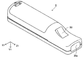
端末装置7は、ユーザが把持可能な程度の大きさであり、ユーザは端末装置7を手に持って動かしたり、あるいは、端末装置7を自由な位置に配置したりして使用することが可能である。詳細な構成は後述するが、端末装置7は、表示手段であるLCD(Liquid Crystal Display:液晶表示装置)51、および、入力手段(後述するタッチパネル52やジャイロセンサ64等)を備える。端末装置7とゲーム装置3とは無線(有線であってもよい)によって通信可能である。端末装置7は、ゲーム装置3で生成された画像(例えばゲーム画像)のデータをゲーム装置3から受信し、画像をLCD51に表示する。なお、本実施形態では表示装置としてLCDを用いているが、端末装置7は、例えばEL(Electro Luminescence:電界発光)を利用した表示装置等、他の任意の表示装置を有していてもよい。また、端末装置7は、自機に対する操作に基づく操作データをゲーム装置3に送信する。   The terminal device 7 is large enough to be gripped by the user, and can be used by the user holding the terminal device 7 in his / her hand or placing the terminal device 7 in a free position. It is. Although the detailed configuration will be described later, the terminal device 7 includes an LCD (Liquid Crystal Display) 51 that is a display means, and input means (a touch panel 52, a gyro sensor 64, and the like described later). The terminal device 7 and the game device 3 can communicate wirelessly (may be wired). The terminal device 7 receives data of an image (for example, a game image) generated by the game device 3 from the game device 3 and displays the image on the LCD 51. In the present embodiment, an LCD is used as the display device. However, the terminal device 7 may have any other display device such as a display device using EL (Electro Luminescence). . In addition, the terminal device 7 transmits operation data based on an operation on the own device to the game device 3.

[2.ゲーム装置3の内部構成]
次に、図2を参照して、ゲーム装置3の内部構成について説明する。図2は、ゲーム装置3の内部構成を示すブロック図である。ゲーム装置3は、CPU(Central Processing Unit)10、システムLSI11、外部メインメモリ12、ROM/RTC13、ディスクドライブ14、およびAV−IC15等を有する。
[2. Internal configuration of game device 3]
Next, the internal configuration of the game apparatus 3 will be described with reference to FIG. FIG. 2 is a block diagram showing an internal configuration of the game apparatus 3. The game apparatus 3 includes a CPU (Central Processing Unit) 10, a system LSI 11, an external main memory 12, a ROM / RTC 13, a disk drive 14, an AV-IC 15, and the like.

CPU10は、光ディスク4に記憶されたゲームプログラムを実行することによってゲーム処理を実行するものであり、ゲームプロセッサとして機能する。CPU10は、システムLSI11に接続される。システムLSI11には、CPU10の他、外部メインメモリ12、ROM/RTC13、ディスクドライブ14およびAV−IC15が接続される。システムLSI11は、それに接続される各構成要素間におけるデータ転送の制御、表示すべき画像の生成、外部装置からのデータの取得等の処理を行う。なお、システムLSI11の内部構成については後述する。揮発性の外部メインメモリ12は、光ディスク4から読み出されたゲームプログラムや、フラッシュメモリ17から読み出されたゲームプログラム等のプログラムを記憶したり、各種データを記憶したりするものであり、CPU10のワーク領域やバッファ領域として用いられる。ROM/RTC13は、ゲーム装置3の起動用のプログラムが組み込まれるROM(いわゆるブートROM)と、時間をカウントするクロック回路(RTC:Real Time Clock)とを有する。ディスクドライブ14は、光ディスク4からプログラムデータやテクスチャデータ等を読み出し、後述する内部メインメモリ11eまたは外部メインメモリ12に読み出したデータを書き込む。   The CPU 10 executes a game process by executing a game program stored on the optical disc 4, and functions as a game processor. The CPU 10 is connected to the system LSI 11. In addition to the CPU 10, an external main memory 12, a ROM / RTC 13, a disk drive 14, and an AV-IC 15 are connected to the system LSI 11. The system LSI 11 performs processing such as control of data transfer between components connected thereto, generation of an image to be displayed, and acquisition of data from an external device. The internal configuration of the system LSI 11 will be described later. The volatile external main memory 12 stores a program such as a game program read from the optical disc 4 or a game program read from the flash memory 17, or stores various data. Used as a work area and buffer area. The ROM / RTC 13 includes a ROM (so-called boot ROM) in which a program for starting the game apparatus 3 is incorporated, and a clock circuit (RTC: Real Time Clock) that counts time. The disk drive 14 reads program data, texture data, and the like from the optical disk 4 and writes the read data to an internal main memory 11e or an external main memory 12 described later.

システムLSI11には、入出力プロセッサ(I/Oプロセッサ)11a、GPU(Graphics Processor Unit)11b、DSP(Digital Signal Processor)11c、VRAM(Video RAM)11d、および内部メインメモリ11eが設けられる。図示は省略するが、これらの構成要素11a〜11eは内部バスによって互いに接続される。   The system LSI 11 is provided with an input / output processor (I / O processor) 11a, a GPU (Graphics Processor Unit) 11b, a DSP (Digital Signal Processor) 11c, a VRAM (Video RAM) 11d, and an internal main memory 11e. Although not shown, these components 11a to 11e are connected to each other by an internal bus.

GPU11bは、描画手段の一部を形成し、CPU10からのグラフィクスコマンド(作画命令)に従って画像を生成する。VRAM11dは、GPU11bがグラフィクスコマンドを実行するために必要なデータ(ポリゴンデータやテクスチャデータ等のデータ)を記憶する。画像が生成される際には、GPU11bは、VRAM11dに記憶されたデータを用いて画像データを作成する。なお、本実施形態においては、ゲーム装置3は、テレビ2に表示するゲーム画像と、端末装置7に表示するゲーム画像との両方を生成する。以下では、テレビ2に表示されるゲーム画像を「テレビ用ゲーム画像」と呼び、端末装置7に表示されるゲーム画像を「端末用ゲーム画像」と呼ぶことがある。   The GPU 11b forms part of a drawing unit and generates an image according to a graphics command (drawing command) from the CPU 10. The VRAM 11d stores data (data such as polygon data and texture data) necessary for the GPU 11b to execute the graphics command. When an image is generated, the GPU 11b creates image data using data stored in the VRAM 11d. In the present embodiment, the game apparatus 3 generates both a game image to be displayed on the television 2 and a game image to be displayed on the terminal device 7. Hereinafter, a game image displayed on the television 2 may be referred to as a “television game image”, and a game image displayed on the terminal device 7 may be referred to as a “terminal game image”.

DSP11cは、オーディオプロセッサとして機能し、内部メインメモリ11eや外部メインメモリ12に記憶されるサウンドデータや音波形(音色)データを用いて、音声データを生成する。なお、本実施形態においては、ゲーム音声についてもゲーム画像と同様、テレビ2のスピーカから出力するゲーム音声と、端末装置7のスピーカから出力するゲーム音声との両方が生成される。以下では、テレビ2から出力されるゲーム音声を「テレビ用ゲーム音声」と呼び、端末装置7から出力されるゲーム音声を「端末用ゲーム音声」と呼ぶことがある。   The DSP 11c functions as an audio processor, and generates sound data using sound data and sound waveform (tone color) data stored in the internal main memory 11e and the external main memory 12. In the present embodiment, both the game sound output from the speaker of the television 2 and the game sound output from the speaker of the terminal device 7 are generated for the game sound as well as the game image. Hereinafter, the game sound output from the television 2 may be referred to as “television game sound”, and the game sound output from the terminal device 7 may be referred to as “terminal game sound”.

上記のようにゲーム装置3において生成される画像および音声のうちで、テレビ2において出力される画像および音声のデータは、AV−IC15によって読み出される。AV−IC15は、読み出した画像データをAVコネクタ16を介してテレビ2に出力するとともに、読み出した音声データを、テレビ2に内蔵されるスピーカ2aに出力する。これによって、テレビ2に画像が表示されるとともにスピーカ2aから音が出力される。   Of the images and sounds generated by the game apparatus 3 as described above, image and sound data output by the television 2 is read by the AV-IC 15. The AV-IC 15 outputs the read image data to the television 2 via the AV connector 16, and outputs the read audio data to the speaker 2 a built in the television 2. Thus, an image is displayed on the television 2 and a sound is output from the speaker 2a.

また、ゲーム装置3において生成される画像および音声のうちで、端末装置7において出力される画像および音声のデータは、入出力プロセッサ11a等によって端末装置7へ送信される。入出力プロセッサ11a等による端末装置7へのデータの送信については後述する。   Of the images and sounds generated by the game apparatus 3, the image and sound data output from the terminal apparatus 7 is transmitted to the terminal apparatus 7 by the input / output processor 11a and the like. Data transmission to the terminal device 7 by the input / output processor 11a and the like will be described later.

入出力プロセッサ11aは、それに接続される構成要素との間でデータの送受信を実行したり、外部装置からのデータのダウンロードを実行したりする。入出力プロセッサ11aは、フラッシュメモリ17、ネットワーク通信モジュール18、コントローラ通信モジュール19、拡張コネクタ20、メモリカード用コネクタ21、コーデックLSI27に接続される。また、ネットワーク通信モジュール18にはアンテナ22が接続される。コントローラ通信モジュール19にはアンテナ23が接続される。コーデックLSI27は端末通信モジュール28に接続され、端末通信モジュール28にはアンテナ29が接続される。   The input / output processor 11a performs transmission / reception of data to / from components connected to the input / output processor 11a and downloads data from an external device. The input / output processor 11a is connected to the flash memory 17, the network communication module 18, the controller communication module 19, the expansion connector 20, the memory card connector 21, and the codec LSI 27. An antenna 22 is connected to the network communication module 18. An antenna 23 is connected to the controller communication module 19. The codec LSI 27 is connected to a terminal communication module 28, and an antenna 29 is connected to the terminal communication module 28.

ゲーム装置3は、インターネット等のネットワークに接続して外部情報処理装置(例えば他のゲーム装置や、各種サーバや、各種情報処理装置等)と通信を行うことが可能である。すなわち、入出力プロセッサ11aは、ネットワーク通信モジュール18およびアンテナ22を介してインターネット等のネットワークに接続し、ネットワークに接続される外部情報処理装置と通信することができる。入出力プロセッサ11aは、定期的にフラッシュメモリ17にアクセスし、ネットワークへ送信する必要があるデータの有無を検出し、当該データが有る場合には、ネットワーク通信モジュール18およびアンテナ22を介してネットワークに送信する。また、入出力プロセッサ11aは、外部情報処理装置から送信されてくるデータやダウンロードサーバからダウンロードしたデータを、ネットワーク、アンテナ22およびネットワーク通信モジュール18を介して受信し、受信したデータをフラッシュメモリ17に記憶する。CPU10はゲームプログラムを実行することにより、フラッシュメモリ17に記憶されたデータを読み出してゲームプログラムで利用する。フラッシュメモリ17には、ゲーム装置3と外部情報処理装置との間で送受信されるデータの他、ゲーム装置3を利用してプレイしたゲームのセーブデータ(ゲームの結果データまたは途中データ)が記憶されてもよい。また、フラッシュメモリ17にはゲームプログラムが記憶されてもよい。   The game apparatus 3 is connected to a network such as the Internet and can communicate with an external information processing apparatus (for example, other game apparatuses, various servers, various information processing apparatuses, etc.). That is, the input / output processor 11a is connected to a network such as the Internet via the network communication module 18 and the antenna 22, and can communicate with an external information processing apparatus connected to the network. The input / output processor 11a periodically accesses the flash memory 17 to detect the presence / absence of data that needs to be transmitted to the network. Send. Further, the input / output processor 11a receives data transmitted from the external information processing apparatus or data downloaded from the download server via the network, the antenna 22 and the network communication module 18, and receives the received data in the flash memory 17. Remember. By executing the game program, the CPU 10 reads out the data stored in the flash memory 17 and uses it in the game program. In addition to data transmitted and received between the game apparatus 3 and the external information processing apparatus, the flash memory 17 stores game save data (game result data or intermediate data) played using the game apparatus 3. May be. The flash memory 17 may store a game program.

また、ゲーム装置3は、コントローラ5からの操作データを受信することが可能である。すなわち、入出力プロセッサ11aは、コントローラ5から送信される操作データをアンテナ23およびコントローラ通信モジュール19を介して受信し、内部メインメモリ11eまたは外部メインメモリ12のバッファ領域に記憶(一時記憶)する。   The game apparatus 3 can receive operation data from the controller 5. That is, the input / output processor 11a receives the operation data transmitted from the controller 5 via the antenna 23 and the controller communication module 19, and stores (temporarily stores) it in the buffer area of the internal main memory 11e or the external main memory 12.

また、ゲーム装置3は、端末装置7との間で画像や音声等のデータを送受信することが可能である。入出力プロセッサ11aは、端末装置7へゲーム画像(端末用ゲーム画像)を送信する場合、GPU11bが生成したゲーム画像のデータをコーデックLSI27へ出力する。コーデックLSI27は、入出力プロセッサ11aからの画像データに対して所定の圧縮処理を行う。端末通信モジュール28は、端末装置7との間で無線通信を行う。したがって、コーデックLSI27によって圧縮された画像データは、端末通信モジュール28によってアンテナ29を介して端末装置7へ送信される。なお、本実施形態では、ゲーム装置3から端末装置7へ送信される画像データはゲームに用いるものであり、ゲームにおいては表示される画像に遅延が生じるとゲームの操作性に悪影響が出る。そのため、ゲーム装置3から端末装置7への画像データの送信に関しては、できるだけ遅延が生じないようにすることが好ましい。したがって、本実施形態では、コーデックLSI27は、例えばH.264規格といった高効率の圧縮技術を用いて画像データを圧縮する。なお、それ以外の圧縮技術を用いてもよいし、通信速度が十分である場合には無圧縮で画像データを送信する構成であってもよい。また、端末通信モジュール28は、例えばWi−Fiの認証を受けた通信モジュールであり、例えばIEEE802.11n規格で採用されるMIMO(Multiple Input Multiple Output)の技術を用いて端末装置7との間の無線通信を高速に行うようにしてもよいし、他の通信方式を用いてもよい。   Further, the game apparatus 3 can transmit and receive data such as images and sounds to and from the terminal device 7. When transmitting a game image (terminal game image) to the terminal device 7, the input / output processor 11 a outputs the game image data generated by the GPU 11 b to the codec LSI 27. The codec LSI 27 performs predetermined compression processing on the image data from the input / output processor 11a. The terminal communication module 28 performs wireless communication with the terminal device 7. Therefore, the image data compressed by the codec LSI 27 is transmitted to the terminal device 7 via the antenna 29 by the terminal communication module 28. In the present embodiment, the image data transmitted from the game apparatus 3 to the terminal apparatus 7 is used for the game, and if the displayed image is delayed in the game, the operability of the game is adversely affected. For this reason, it is preferable that the transmission of image data from the game apparatus 3 to the terminal device 7 is as little as possible. Therefore, in this embodiment, the codec LSI 27 is, for example, H.264. The image data is compressed using a highly efficient compression technique such as H.264 standard. Other compression techniques may be used, and when the communication speed is sufficient, the image data may be transmitted without compression. The terminal communication module 28 is a communication module that has received, for example, Wi-Fi authentication. For example, the terminal communication module 28 uses a MIMO (Multiple Input Multiple Output) technique adopted in the IEEE802.11n standard. Wireless communication may be performed at high speed, or another communication method may be used.

また、ゲーム装置3は、画像データの他、音声データを端末装置7へ送信する。すなわち、入出力プロセッサ11aは、DSP11cが生成した音声データを、コーデックLSI27を介して端末通信モジュール28へ出力する。コーデックLSI27は、音声データに対しても画像データと同様に圧縮処理を行う。音声データに対する圧縮の方式は、どのような方式であってもよいが、圧縮率が高く、音声の劣化が少ない方式が好ましい。また、他の実施形態においては、音声データは圧縮されずに送信されてもよい。端末通信モジュール28は、圧縮された画像データおよび音声データを、アンテナ29を介して端末装置7へ送信する。   In addition to the image data, the game apparatus 3 transmits audio data to the terminal device 7. That is, the input / output processor 11 a outputs the audio data generated by the DSP 11 c to the terminal communication module 28 via the codec LSI 27. The codec LSI 27 performs compression processing on the audio data in the same manner as the image data. The compression method for the audio data may be any method, but a method with a high compression rate and less deterioration of the sound is preferable. In other embodiments, audio data may be transmitted without being compressed. The terminal communication module 28 transmits the compressed image data and audio data to the terminal device 7 via the antenna 29.

さらに、ゲーム装置3は、上記画像データおよび音声データの他に、必要に応じて各種の制御データを端末装置7へ送信する。制御データは、端末装置7が備える構成要素に対する制御指示を表すデータであり、例えばマーカ部(図11に示すマーカ部55)の点灯を制御する指示や、カメラ(図11に示すカメラ56)の撮像を制御する指示等を表す。入出力プロセッサ11aは、CPU10の指示に応じて制御データを端末装置7へ送信する。なお、この制御データに関して、本実施形態ではコーデックLSI27はデータの圧縮処理を行わないが、他の実施形態においては圧縮処理を行うようにしてもよい。なお、ゲーム装置3から端末装置7へ送信される上述のデータは、必要に応じて暗号化がされていてもよいし、されていなくともよい。 Further, the game apparatus 3 transmits various control data to the terminal apparatus 7 as necessary in addition to the image data and the sound data. The control data is data representing a control instruction for a component included in the terminal device 7, and for example, an instruction to control lighting of the marker unit (marker unit 55 shown in FIG. 11 ) or a camera (camera 56 shown in FIG. 11 ). Indicates an instruction to control imaging. The input / output processor 11 a transmits control data to the terminal device 7 in accordance with an instruction from the CPU 10. With respect to this control data, the codec LSI 27 does not perform data compression processing in the present embodiment, but may perform compression processing in other embodiments. Note that the above-described data transmitted from the game device 3 to the terminal device 7 may or may not be encrypted as necessary.

また、ゲーム装置3は、端末装置7から各種データを受信可能である。詳細は後述するが、本実施形態では、端末装置7は、操作データ、画像データ、および音声データを送信する。端末装置7から送信される各データはアンテナ29を介して端末通信モジュール28によって受信される。ここで、端末装置7からの画像データおよび音声データは、ゲーム装置3から端末装置7への画像データおよび音声データと同様の圧縮処理が施されている。したがって、これら画像データおよび音声データについては、端末通信モジュール28からコーデックLSI27に送られ、コーデックLSI27によって伸張処理が施されて入出力プロセッサ11aに出力される。一方、端末装置7からの操作データに関しては、画像や音声に比べてデータ量が少ないので、圧縮処理が施されていなくともよい。また、必要に応じて暗号化がされていてもよいし、されていなくともよい。したがって、操作データは、端末通信モジュール28で受信された後、コーデックLSI27を介して入出力プロセッサ11aに出力される。入出力プロセッサ11aは、端末装置7から受信したデータを、内部メインメモリ11eまたは外部メインメモリ12のバッファ領域に記憶(一時記憶)する。   The game apparatus 3 can receive various data from the terminal device 7. Although details will be described later, in the present embodiment, the terminal device 7 transmits operation data, image data, and audio data. Each data transmitted from the terminal device 7 is received by the terminal communication module 28 via the antenna 29. Here, the image data and audio data from the terminal device 7 are subjected to the same compression processing as the image data and audio data from the game device 3 to the terminal device 7. Therefore, these image data and audio data are sent from the terminal communication module 28 to the codec LSI 27, subjected to expansion processing by the codec LSI 27, and output to the input / output processor 11a. On the other hand, the operation data from the terminal device 7 has a smaller amount of data than images and sounds, and therefore may not be subjected to compression processing. Further, encryption may or may not be performed as necessary. Accordingly, the operation data is received by the terminal communication module 28 and then output to the input / output processor 11 a via the codec LSI 27. The input / output processor 11a stores (temporarily stores) the data received from the terminal device 7 in the buffer area of the internal main memory 11e or the external main memory 12.

また、ゲーム装置3は、他の機器や外部記憶媒体に接続することが可能である。すなわち、入出力プロセッサ11aには、拡張コネクタ20およびメモリカード用コネクタ21が接続される。拡張コネクタ20は、USBやSCSIのようなインターフェースのためのコネクタである。拡張コネクタ20に対しては、外部記憶媒体のようなメディアを接続したり、他のコントローラ等の周辺機器を接続したり、有線の通信用コネクタを接続することによってネットワーク通信モジュール18に替えてネットワークとの通信を行ったりすることができる。メモリカード用コネクタ21は、メモリカードのような外部記憶媒体を接続するためのコネクタである。例えば、入出力プロセッサ11aは、拡張コネクタ20やメモリカード用コネクタ21を介して外部記憶媒体にアクセスし、外部記憶媒体にデータを保存したり、外部記憶媒体からデータを読み出したりすることができる。   Further, the game apparatus 3 can be connected to another device or an external storage medium. That is, the expansion connector 20 and the memory card connector 21 are connected to the input / output processor 11a. The expansion connector 20 is a connector for an interface such as USB or SCSI. A network such as an external storage medium is connected to the expansion connector 20, a peripheral device such as another controller is connected, or a wired communication connector is connected to replace the network communication module 18 with a network. You can communicate with. The memory card connector 21 is a connector for connecting an external storage medium such as a memory card. For example, the input / output processor 11a can access an external storage medium via the expansion connector 20 or the memory card connector 21 to store data in the external storage medium or read data from the external storage medium.

ゲーム装置3には、電源ボタン24、リセットボタン25、およびイジェクトボタン26が設けられる。電源ボタン24およびリセットボタン25は、システムLSI11に接続される。電源ボタン24がオンされると、図示しないACアダプタによって外部の電源からゲーム装置3の各構成要素に対して電力が供給される。リセットボタン25が押されると、システムLSI11は、ゲーム装置3の起動プログラムを再起動する。イジェクトボタン26は、ディスクドライブ14に接続される。イジェクトボタン26が押されると、ディスクドライブ14から光ディスク4が排出される。   The game apparatus 3 is provided with a power button 24, a reset button 25, and an eject button 26. The power button 24 and the reset button 25 are connected to the system LSI 11. When the power button 24 is turned on, power is supplied to each component of the game apparatus 3 from an external power source by an AC adapter (not shown). When the reset button 25 is pressed, the system LSI 11 restarts the boot program for the game apparatus 3. The eject button 26 is connected to the disk drive 14. When the eject button 26 is pressed, the optical disk 4 is ejected from the disk drive 14.

なお、他の実施形態においては、ゲーム装置3が備える各構成要素のうちでいくつかの構成要素は、ゲーム装置3とは別体の拡張機器として構成されてもよい。このとき、拡張機器は、例えば上記拡張コネクタ20を介してゲーム装置3と接続されるようにしてもよい。具体的には、拡張機器は、例えば上記コーデックLSI27、端末通信モジュール28およびアンテナ29の各構成要素を備えており、拡張コネクタ20に対して着脱可能であってもよい。これによれば、上記各構成要素を備えていないゲーム装置に対して上記拡張機器を接続することによって、当該ゲーム装置を端末装置7と通信可能な構成とすることができる。   In other embodiments, some of the components included in the game apparatus 3 may be configured as expansion devices that are separate from the game apparatus 3. At this time, the expansion device may be connected to the game apparatus 3 via the expansion connector 20, for example. Specifically, the extension device includes, for example, each component of the codec LSI 27, the terminal communication module 28, and the antenna 29, and may be detachable from the extension connector 20. According to this, the said game device can be set as the structure which can communicate with the terminal device 7 by connecting the said expansion apparatus with respect to the game device which is not provided with said each component.

[3.コントローラ5の構成]
次に、図3〜図7を参照して、コントローラ5について説明する。上述のように、コントローラ5は、メインコントローラ8とサブコントローラ9とによって構成される。図3は、メインコントローラ8の外観構成を示す斜視図である。図4は、メインコントローラ8の外観構成を示す斜視図である。図3は、メインコントローラ8の上側後方から見た斜視図であり、図4は、メインコントローラ8を下側前方から見た斜視図である。
[3. Configuration of controller 5]
Next, the controller 5 will be described with reference to FIGS. As described above, the controller 5 includes the main controller 8 and the sub controller 9. FIG. 3 is a perspective view showing an external configuration of the main controller 8. FIG. 4 is a perspective view showing an external configuration of the main controller 8. FIG. 3 is a perspective view of the main controller 8 as seen from the upper rear side, and FIG. 4 is a perspective view of the main controller 8 as seen from the lower front side.

図3および図4において、メインコントローラ8は、例えばプラスチック成型によって形成されたハウジング31を有している。ハウジング31は、その前後方向(図3に示すZ1軸方向)を長手方向とした略直方体形状を有しており、全体として大人や子供の片手で把持可能な大きさである。ユーザは、メインコントローラ8に設けられたボタンを押下すること、および、メインコントローラ8自体を動かしてその位置や姿勢(傾き)を変えることによってゲーム操作を行うことができる。   3 and 4, the main controller 8 has a housing 31 formed by plastic molding, for example. The housing 31 has a substantially rectangular parallelepiped shape whose longitudinal direction is the front-rear direction (Z1 axis direction shown in FIG. 3), and is a size that can be gripped with one hand of an adult or a child as a whole. The user can perform a game operation by pressing a button provided on the main controller 8 and moving the main controller 8 itself to change its position and posture (tilt).

ハウジング31には、複数の操作ボタンが設けられる。図3に示すように、ハウジング31の上面には、十字ボタン32a、1番ボタン32b、2番ボタン32c、Aボタン32d、マイナスボタン32e、ホームボタン32f、プラスボタン32g、および電源ボタン32hが設けられる。本明細書では、これらのボタン32a〜32hが設けられるハウジング31の上面を「ボタン面」と呼ぶことがある。一方、図4に示すように、ハウジング31の下面には凹部が形成されており、当該凹部の後面側傾斜面にはBボタン32iが設けられる。これらの各操作ボタン32a〜32iには、ゲーム装置3が実行する情報処理プログラムに応じた機能が適宜割り当てられる。また、電源ボタン32hは遠隔からゲーム装置3本体の電源をオン/オフするためのものである。ホームボタン32fおよび電源ボタン32hは、その上面がハウジング31の上面に埋没している。これによって、ユーザがホームボタン32fまたは電源ボタン32hを誤って押下することを防止することができる。   The housing 31 is provided with a plurality of operation buttons. As shown in FIG. 3, a cross button 32a, a first button 32b, a second button 32c, an A button 32d, a minus button 32e, a home button 32f, a plus button 32g, and a power button 32h are provided on the upper surface of the housing 31. It is done. In the present specification, the upper surface of the housing 31 on which these buttons 32a to 32h are provided may be referred to as a “button surface”. On the other hand, as shown in FIG. 4, a recess is formed on the lower surface of the housing 31, and a B button 32i is provided on the rear inclined surface of the recess. A function corresponding to the information processing program executed by the game apparatus 3 is appropriately assigned to each of the operation buttons 32a to 32i. The power button 32h is for remotely turning on / off the main body of the game apparatus 3. The home button 32 f and the power button 32 h are embedded in the upper surface of the housing 31. Thereby, it is possible to prevent the user from pressing the home button 32f or the power button 32h by mistake.

ハウジング31の後面にはコネクタ33が設けられている。コネクタ33は、メインコントローラ8に他の機器(例えば、サブコントローラ9や他のセンサユニット等)を接続するために利用される。また、ハウジング31の後面におけるコネクタ33の両側には、上記他の機器が容易に離脱することを防止するために係止穴33aが設けられている。   A connector 33 is provided on the rear surface of the housing 31. The connector 33 is used for connecting other devices (for example, the sub-controller 9 and other sensor units) to the main controller 8. Further, locking holes 33a are provided on both sides of the connector 33 on the rear surface of the housing 31 in order to prevent the other devices from being easily detached.

ハウジング31上面の後方には複数(図3では4つ)のLED34a〜34dが設けられる。ここで、コントローラ5(メインコントローラ8)には、他のコントローラと区別するためにコントローラ種別(番号)が付与される。各LED34a〜34dは、コントローラ5に現在設定されている上記コントローラ種別をユーザに通知したり、コントローラ5の電池残量をユーザに通知したりする等の目的で用いられる。具体的には、コントローラ5を用いてゲーム操作が行われる際、上記コントローラ種別に応じて複数のLED34a〜34dのいずれか1つが点灯する。   A plurality (four in FIG. 3) of LEDs 34 a to 34 d are provided behind the upper surface of the housing 31. Here, a controller type (number) is assigned to the controller 5 (main controller 8) in order to distinguish it from other controllers. The LEDs 34a to 34d are used for the purpose of notifying the user of the controller type currently set in the controller 5 and notifying the user of the remaining battery level of the controller 5. Specifically, when a game operation is performed using the controller 5, any one of the plurality of LEDs 34a to 34d is turned on according to the controller type.

また、メインコントローラ8は撮像情報演算部35(図6)を有しており、図4に示すように、ハウジング31前面には撮像情報演算部35の光入射面35aが設けられる。光入射面35aは、マーカ6Rおよび6Lからの赤外光を少なくとも透過する材質で構成される。   Further, the main controller 8 has an imaging information calculation unit 35 (FIG. 6). As shown in FIG. 4, a light incident surface 35a of the imaging information calculation unit 35 is provided on the front surface of the housing 31. The light incident surface 35a is made of a material that transmits at least infrared light from the markers 6R and 6L.

ハウジング31上面における1番ボタン32bとホームボタン32fとの間には、メインコントローラ8に内蔵されるスピーカ47(図5)からの音を外部に放出するための音抜き孔31aが形成されている。   Between the first button 32b and the home button 32f on the upper surface of the housing 31, there is formed a sound release hole 31a for emitting sound from the speaker 47 (FIG. 5) built in the main controller 8 to the outside. .

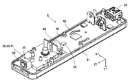
次に、図5および図6を参照して、メインコントローラ8の内部構造について説明する。図5および図6は、メインコントローラ8の内部構造を示す図である。なお、図5は、メインコントローラ8の上筐体(ハウジング31の一部)を外した状態を示す斜視図である。図6は、メインコントローラ8の下筐体(ハウジング31の一部)を外した状態を示す斜視図である。図6に示す斜視図は、図5に示す基板30を裏面から見た斜視図となっている。   Next, the internal structure of the main controller 8 will be described with reference to FIGS. 5 and 6 are diagrams showing the internal structure of the main controller 8. FIG. FIG. 5 is a perspective view showing a state in which the upper housing (a part of the housing 31) of the main controller 8 is removed. FIG. 6 is a perspective view showing a state in which the lower casing (a part of the housing 31) of the main controller 8 is removed. The perspective view shown in FIG. 6 is a perspective view of the substrate 30 shown in FIG.

図5において、ハウジング31の内部には基板30が固設されており、当該基板30の上主面上に各操作ボタン32a〜32h、各LED34a〜34d、加速度センサ37、アンテナ45、およびスピーカ47等が設けられる。これらは、基板30等に形成された配線(図示せず)によってマイクロコンピュータ(Micro Computer:マイコン)42(図6参照)に接続される。本実施形態では、加速度センサ37は、X1軸方向に関してメインコントローラ8の中心からずれた位置に配置されている。これによって、メインコントローラ8をZ1軸回りに回転させたときのメインコントローラ8の動きが算出しやすくなる。また、加速度センサ37は、長手方向(Z1軸方向)に関してメインコントローラ8の中心よりも前方に配置されている。また、無線モジュール44(図6)およびアンテナ45によって、コントローラ5(メインコントローラ8)がワイヤレスコントローラとして機能する。   In FIG. 5, a substrate 30 is fixed inside the housing 31, and operation buttons 32 a to 32 h, LEDs 34 a to 34 d, an acceleration sensor 37, an antenna 45, and a speaker 47 are provided on the upper main surface of the substrate 30. Etc. are provided. These are connected to a microcomputer (microcomputer) 42 (see FIG. 6) by wiring (not shown) formed on the substrate 30 and the like. In the present embodiment, the acceleration sensor 37 is arranged at a position shifted from the center of the main controller 8 in the X1 axis direction. This makes it easier to calculate the movement of the main controller 8 when the main controller 8 is rotated about the Z1 axis. Further, the acceleration sensor 37 is disposed in front of the center of the main controller 8 in the longitudinal direction (Z1-axis direction). Further, the controller 5 (main controller 8) functions as a wireless controller by the wireless module 44 (FIG. 6) and the antenna 45.

一方、図6において、基板30の下主面上の前端縁に撮像情報演算部35が設けられる。撮像情報演算部35は、メインコントローラ8の前方から順に赤外線フィルタ38、レンズ39、撮像素子40、および画像処理回路41を備えている。これらの部材38〜41はそれぞれ基板30の下主面に取り付けられる。   On the other hand, in FIG. 6, an imaging information calculation unit 35 is provided at the front edge on the lower main surface of the substrate 30. The imaging information calculation unit 35 includes an infrared filter 38, a lens 39, an imaging element 40, and an image processing circuit 41 in order from the front of the main controller 8. These members 38 to 41 are respectively attached to the lower main surface of the substrate 30.

さらに、基板30の下主面上には、上記マイコン42およびバイブレータ46が設けられている。バイブレータ46は、例えば振動モータやソレノイドであり、基板30等に形成された配線によってマイコン42と接続される。マイコン42の指示によりバイブレータ46が作動することによってメインコントローラ8に振動が発生する。これによって、メインコントローラ8を把持しているユーザの手にその振動が伝達される、いわゆる振動対応ゲームを実現することができる。本実施形態では、バイブレータ46は、ハウジング31のやや前方寄りに配置される。つまり、バイブレータ46がメインコントローラ8の中心よりも端側に配置することによって、バイブレータ46の振動によりメインコントローラ8全体を大きく振動させることができる。また、コネクタ33は、基板30の下主面上の後端縁に取り付けられる。なお、図5および図6に示す他、メインコントローラ8は、マイコン42の基本クロックを生成する水晶振動子、スピーカ47に音声信号を出力するアンプ等を備えている。   Further, the microcomputer 42 and the vibrator 46 are provided on the lower main surface of the substrate 30. The vibrator 46 is, for example, a vibration motor or a solenoid, and is connected to the microcomputer 42 by wiring formed on the substrate 30 or the like. The vibration is generated in the main controller 8 by the operation of the vibrator 46 according to the instruction of the microcomputer 42. As a result, a so-called vibration-compatible game in which the vibration is transmitted to the user's hand holding the main controller 8 can be realized. In the present embodiment, the vibrator 46 is disposed slightly forward of the housing 31. That is, by arranging the vibrator 46 on the end side of the center of the main controller 8, the entire main controller 8 can be vibrated greatly by the vibration of the vibrator 46. The connector 33 is attached to the rear edge on the lower main surface of the substrate 30. 5 and 6, the main controller 8 includes a crystal resonator that generates a basic clock of the microcomputer 42, an amplifier that outputs an audio signal to the speaker 47, and the like.

図7は、サブコントローラ9の外観構成を示す斜視図である。サブコントローラ9は、例えばプラスチック成型によって形成されたハウジング80を有している。ハウジング80は、メインコントローラ8と同様に、全体として大人や子供の片手で把持可能な大きさである。このサブコントローラ9を用いることによっても、プレイヤは、ボタンやスティックを操作することと、コントローラ自体の位置や向きを変えることとによって、ゲーム操作を行うことができる。   FIG. 7 is a perspective view showing an external configuration of the sub-controller 9. The sub-controller 9 has a housing 80 formed by plastic molding, for example. Similar to the main controller 8, the housing 80 is sized so that it can be grasped with one hand of an adult or child as a whole. By using the sub-controller 9, the player can perform game operations by operating buttons and sticks and changing the position and orientation of the controller itself.

図7に示すように、ハウジング80の上面(Y2軸負方向側の面)の先端側(Z2軸正側)には、アナログジョイスティック81が設けられる。また、図示されないが、ハウジング80の先端には、後方にやや傾斜する先端面が設けられており、この先端面には、上下方向(図7に示すY2軸方向)に並べて、CボタンおよびZボタンが設けられる。アナログジョイスティック81および各ボタン(CボタンおよびZボタン)には、ゲーム装置3が実行するゲームプログラムに応じてそれぞれ適宜の機能が割り当てられる。なお、アナログジョイスティック81および各ボタンを包括的に「操作部82(図8参照)」と呼ぶことがある。   As shown in FIG. 7, an analog joystick 81 is provided on the distal end side (Z2 axis positive side) of the upper surface (surface on the Y2 axis negative direction side) of the housing 80. Although not shown in the drawings, the front end of the housing 80 is provided with a front end surface that is slightly inclined to the rear, and on the front end surface, the C button and the Z button are arranged in the vertical direction (Y2 axis direction shown in FIG. 7). A button is provided. An appropriate function is assigned to the analog joystick 81 and each button (C button and Z button) according to the game program executed by the game apparatus 3. The analog joystick 81 and each button may be collectively referred to as “operation unit 82 (see FIG. 8)”.

また、図7では示されないが、サブコントローラ9は、ハウジング80の内部に加速度センサ(図8に示す加速度センサ83)を有している。本実施形態においては、加速度センサ83は、メインコントローラ8の加速度センサ37と同様のものが用いられる。ただし、加速度センサ83は、加速度センサ37とは異なるものであってもよく、例えば所定の1軸または2軸の加速度を検出するものであってもよい。   Although not shown in FIG. 7, the sub-controller 9 has an acceleration sensor (acceleration sensor 83 shown in FIG. 8) inside the housing 80. In the present embodiment, the acceleration sensor 83 is the same as the acceleration sensor 37 of the main controller 8. However, the acceleration sensor 83 may be different from the acceleration sensor 37. For example, the acceleration sensor 83 may detect a predetermined one-axis or two-axis acceleration.

また、図7に示すように、ハウジング80の後端にはケーブルの一端が接続されている。図7では示されないが、ケーブルの他端にはコネクタ(図8に示すコネクタ84)が接続される。このコネクタはメインコントローラ8のコネクタ33と接続可能である。つまり、コネクタ33とコネクタ84とを接続することによって、メインコントローラ8とサブコントローラ9とが接続される。   Further, as shown in FIG. 7, one end of the cable is connected to the rear end of the housing 80. Although not shown in FIG. 7, a connector (connector 84 shown in FIG. 8) is connected to the other end of the cable. This connector can be connected to the connector 33 of the main controller 8. That is, the main controller 8 and the sub-controller 9 are connected by connecting the connector 33 and the connector 84.

なお、図3〜図7に示したメインコントローラ8およびサブコントローラ9の形状や、各操作ボタンの形状、加速度センサやバイブレータの数および設置位置等は単なる一例に過ぎず、他の形状、数、および設置位置であってもよい。また、本実施形態では、メインコントローラ8の撮像手段による撮像方向はZ1軸正方向であるが、撮像方向はいずれの方向であってもよい。すなわち、コントローラ5における撮像情報演算部35の位置(撮像情報演算部35の光入射面35a)は、ハウジング31の前面でなくてもよく、ハウジング31の外部から光を取り入れることができれば他の面に設けられてもかまわない。   The shapes of the main controller 8 and the sub controller 9 shown in FIGS. 3 to 7, the shapes of the operation buttons, the number of acceleration sensors and vibrators, and the installation positions are merely examples, and other shapes, numbers, And the installation position. In the present embodiment, the imaging direction by the imaging means of the main controller 8 is the positive Z1-axis direction, but the imaging direction may be any direction. That is, the position of the imaging information calculation unit 35 in the controller 5 (the light incident surface 35a of the imaging information calculation unit 35) does not have to be the front surface of the housing 31, and other surfaces can be used as long as light can be taken in from the outside of the housing 31. May be provided.

図8は、コントローラ5の構成を示すブロック図である。図8に示すように、メインコントローラ8は、操作部32(各操作ボタン32a〜32i)、撮像情報演算部35、通信部36、加速度センサ37、およびジャイロセンサ48を備えている。また、サブコントローラ9は、操作部82および加速度センサ83を備えている。コントローラ5は、自機に対して行われた操作内容を表すデータを操作データとしてゲーム装置3へ送信するものである。なお、以下では、コントローラ5が送信する操作データを「コントローラ操作データ」と呼び、端末装置7が送信する操作データを「端末操作データ」と呼ぶことがある。   FIG. 8 is a block diagram showing the configuration of the controller 5. As shown in FIG. 8, the main controller 8 includes an operation unit 32 (operation buttons 32 a to 32 i), an imaging information calculation unit 35, a communication unit 36, an acceleration sensor 37, and a gyro sensor 48. The sub-controller 9 includes an operation unit 82 and an acceleration sensor 83. The controller 5 transmits data representing the content of the operation performed on the own device to the game apparatus 3 as operation data. Hereinafter, the operation data transmitted from the controller 5 may be referred to as “controller operation data”, and the operation data transmitted from the terminal device 7 may be referred to as “terminal operation data”.

操作部32は、上述した各操作ボタン32a〜32iを含み、各操作ボタン32a〜32iに対する入力状態(各操作ボタン32a〜32iが押下されたか否か)を表す操作ボタンデータを通信部36のマイコン42へ出力する。   The operation unit 32 includes the operation buttons 32a to 32i described above, and the operation button data indicating the input state (whether or not each operation button 32a to 32i is pressed) to each operation button 32a to 32i is transmitted to the microcomputer of the communication unit 36. Output to 42.

撮像情報演算部35は、撮像手段が撮像した画像データを解析してその中で輝度が高い領域を判別してその領域の重心位置やサイズなどを算出するためのシステムである。撮像情報演算部35は、例えば最大200フレーム/秒程度のサンプリング周期を有するので、比較的高速なコントローラ5の動きでも追跡して解析することができる。   The imaging information calculation unit 35 is a system for analyzing the image data captured by the imaging unit, discriminating a region having a high luminance in the image data, and calculating a center of gravity position, a size, and the like of the region. Since the imaging information calculation unit 35 has a sampling period of, for example, about 200 frames / second at the maximum, it can track and analyze even a relatively fast movement of the controller 5.

撮像情報演算部35は、赤外線フィルタ38、レンズ39、撮像素子40、および画像処理回路41を含んでいる。赤外線フィルタ38は、コントローラ5の前方から入射する光から赤外線のみを通過させる。レンズ39は、赤外線フィルタ38を透過した赤外線を集光して撮像素子40へ入射させる。撮像素子40は、例えばCMOSセンサやあるいはCCDセンサのような固体撮像素子であり、レンズ39が集光した赤外線を受光して画像信号を出力する。ここで、撮像対象となる端末装置7のマーカ部55およびマーカ装置6は、赤外光を出力するマーカで構成される。したがって、赤外線フィルタ38を設けることによって、撮像素子40は、赤外線フィルタ38を通過した赤外線だけを受光して画像データを生成するので、撮像対象(マーカ部55および/またはマーカ装置6)の画像をより正確に撮像することができる。以下では、撮像素子40によって撮像された画像を撮像画像と呼ぶ。撮像素子40によって生成された画像データは、画像処理回路41で処理される。画像処理回路41は、撮像画像内における撮像対象の位置を算出する。画像処理回路41は、算出された位置を示す座標を通信部36のマイコン42へ出力する。この座標のデータは、マイコン42によって操作データとしてゲーム装置3に送信される。以下では、上記座標を「マーカ座標」と呼ぶ。マーカ座標はコントローラ5自体の向き(傾斜角度)や位置に対応して変化するので、ゲーム装置3はこのマーカ座標を用いてコントローラ5の向きや位置を算出することができる。   The imaging information calculation unit 35 includes an infrared filter 38, a lens 39, an imaging element 40, and an image processing circuit 41. The infrared filter 38 passes only infrared rays from the light incident from the front of the controller 5. The lens 39 collects the infrared light transmitted through the infrared filter 38 and makes it incident on the image sensor 40. The image sensor 40 is a solid-state image sensor such as a CMOS sensor or a CCD sensor, for example, and receives the infrared light collected by the lens 39 and outputs an image signal. Here, the marker unit 55 and the marker device 6 of the terminal device 7 to be imaged are configured by a marker that outputs infrared light. Therefore, by providing the infrared filter 38, the image sensor 40 receives only the infrared light that has passed through the infrared filter 38 and generates image data. Therefore, the image of the imaging target (the marker unit 55 and / or the marker device 6) is captured. More accurate imaging can be performed. Hereinafter, an image captured by the image sensor 40 is referred to as a captured image. Image data generated by the image sensor 40 is processed by the image processing circuit 41. The image processing circuit 41 calculates the position of the imaging target in the captured image. The image processing circuit 41 outputs coordinates indicating the calculated position to the microcomputer 42 of the communication unit 36. The coordinate data is transmitted to the game apparatus 3 as operation data by the microcomputer 42. Hereinafter, the coordinates are referred to as “marker coordinates”. Since the marker coordinates change corresponding to the direction (tilt angle) and position of the controller 5 itself, the game apparatus 3 can calculate the direction and position of the controller 5 using the marker coordinates.

なお、他の実施形態においては、コントローラ5は画像処理回路41を備えていない構成であってもよく、撮像画像自体がコントローラ5からゲーム装置3へ送信されてもよい。このとき、ゲーム装置3は、画像処理回路41と同様の機能を有する回路あるいはプログラムを有しており、上記マーカ座標を算出するようにしてもよい。   In other embodiments, the controller 5 may not include the image processing circuit 41, and the captured image itself may be transmitted from the controller 5 to the game apparatus 3. At this time, the game apparatus 3 may have a circuit or a program having the same function as the image processing circuit 41, and may calculate the marker coordinates.

加速度センサ37は、コントローラ5の加速度(重力加速度を含む)を検出する、すなわち、コントローラ5に加わる力(重力を含む)を検出する。加速度センサ37は、当該加速度センサ37の検出部に加わっている加速度のうち、センシング軸方向に沿った直線方向の加速度(直線加速度)の値を検出する。例えば、2軸以上の多軸加速度センサの場合には、加速度センサの検出部に加わっている加速度として、各軸に沿った成分の加速度をそれぞれ検出する。なお、加速度センサ37は、例えば静電容量式のMEMS(Micro Electro Mechanical System)型加速度センサであるとするが、他の方式の加速度センサを用いるようにしてもよい。   The acceleration sensor 37 detects the acceleration (including gravity acceleration) of the controller 5, that is, detects the force (including gravity) applied to the controller 5. The acceleration sensor 37 detects the value of the acceleration (linear acceleration) in the linear direction along the sensing axis direction among the accelerations applied to the detection unit of the acceleration sensor 37. For example, in the case of a multi-axis acceleration sensor having two or more axes, the component acceleration along each axis is detected as the acceleration applied to the detection unit of the acceleration sensor. The acceleration sensor 37 is, for example, a capacitive MEMS (Micro Electro Mechanical System) type acceleration sensor, but other types of acceleration sensors may be used.

本実施形態では、加速度センサ37は、コントローラ5を基準とした上下方向(図3に示すY1軸方向)、左右方向(図3に示すX1軸方向)および前後方向(図3に示すZ1軸方向)の3軸方向に関してそれぞれ直線加速度を検出する。加速度センサ37は、各軸に沿った直線方向に関する加速度を検出するものであるため、加速度センサ37からの出力は3軸それぞれの直線加速度の値を表すものとなる。すなわち、検出された加速度は、コントローラ5を基準に設定されるX1Y1Z1座標系(コントローラ座標系)における3次元のベクトルとして表される。   In the present embodiment, the acceleration sensor 37 has a vertical direction (Y1-axis direction shown in FIG. 3), a horizontal direction (X1-axis direction shown in FIG. 3), and a front-back direction (Z1-axis direction shown in FIG. 3) with reference to the controller 5. ) Linear acceleration is detected in each of the three axis directions. Since the acceleration sensor 37 detects acceleration in the linear direction along each axis, the output from the acceleration sensor 37 represents the linear acceleration value of each of the three axes. That is, the detected acceleration is expressed as a three-dimensional vector in the X1Y1Z1 coordinate system (controller coordinate system) set with the controller 5 as a reference.

加速度センサ37が検出した加速度を表すデータ(加速度データ)は、通信部36へ出力される。なお、加速度センサ37が検出した加速度は、コントローラ5自体の向き(傾斜角度)や動きに対応して変化するので、ゲーム装置3は取得された加速度データを用いてコントローラ5の向きや動きを算出することができる。本実施形態では、ゲーム装置3は、取得された加速度データに基づいてコントローラ5の姿勢や傾斜角度等を算出する。   Data representing the acceleration detected by the acceleration sensor 37 (acceleration data) is output to the communication unit 36. The acceleration detected by the acceleration sensor 37 changes in accordance with the direction (tilt angle) and movement of the controller 5 itself, so the game apparatus 3 calculates the direction and movement of the controller 5 using the acquired acceleration data. can do. In the present embodiment, the game apparatus 3 calculates the attitude, tilt angle, and the like of the controller 5 based on the acquired acceleration data.

なお、加速度センサ37(後述する加速度センサ63についても同様)から出力される加速度の信号に基づいて、ゲーム装置3のプロセッサ(例えばCPU10)またはコントローラ5のプロセッサ(例えばマイコン42)等のコンピュータが処理を行うことによって、コントローラ5に関するさらなる情報を推測または算出(判定)することができることは、当業者であれば本明細書の説明から容易に理解できるであろう。例えば、加速度センサ37を搭載するコントローラ5が静止状態であることを前提としてコンピュータ側の処理が実行される場合(すなわち、加速度センサによって検出される加速度が重力加速度のみであるとして処理が実行される場合)、コントローラ5が現実に静止状態であれば、検出された加速度に基づいてコントローラ5の姿勢が重力方向に対して傾いているか否かまたはどの程度傾いているかを知ることができる。具体的には、加速度センサ37の検出軸が鉛直下方向を向いている状態を基準としたとき、1G(重力加速度)がかかっているか否かによって、コントローラ5が基準に対して傾いているか否かを知ることができるし、その大きさによって基準に対してどの程度傾いているかも知ることができる。また、多軸の加速度センサ37の場合には、さらに各軸の加速度の信号に対して処理を施すことによって、重力方向に対してコントローラ5がどの程度傾いているかをより詳細に知ることができる。この場合において、プロセッサは、加速度センサ37からの出力に基づいてコントローラ5の傾斜角度を算出してもよいし、当該傾斜角度を算出せずに、コントローラ5の傾斜方向を算出するようにしてもよい。このように、加速度センサ37をプロセッサと組み合わせて用いることによって、コントローラ5の傾斜角度または姿勢を判定することができる。   A computer such as a processor (for example, CPU 10) of the game apparatus 3 or a processor (for example, the microcomputer 42) of the controller 5 performs processing based on an acceleration signal output from the acceleration sensor 37 (the same applies to an acceleration sensor 63 described later). It can be easily understood by those skilled in the art from the description of the present specification that by performing the above, it is possible to estimate or calculate (determine) further information regarding the controller 5. For example, when processing on the computer side is executed on the assumption that the controller 5 on which the acceleration sensor 37 is mounted is stationary (that is, the processing is executed assuming that the acceleration detected by the acceleration sensor is only gravitational acceleration). When the controller 5 is actually stationary, it can be determined whether or not the attitude of the controller 5 is inclined with respect to the direction of gravity based on the detected acceleration. Specifically, whether or not the controller 5 is inclined with respect to the reference depending on whether or not 1G (gravity acceleration) is applied, based on the state in which the detection axis of the acceleration sensor 37 is directed vertically downward. It is possible to know how much it is inclined with respect to the reference according to its size. Further, in the case of the multi-axis acceleration sensor 37, it is possible to know in detail how much the controller 5 is inclined with respect to the direction of gravity by further processing the acceleration signal of each axis. . In this case, the processor may calculate the tilt angle of the controller 5 based on the output from the acceleration sensor 37, or may calculate the tilt direction of the controller 5 without calculating the tilt angle. Good. Thus, by using the acceleration sensor 37 in combination with the processor, the tilt angle or posture of the controller 5 can be determined.

一方、コントローラ5が動的な状態(コントローラ5が動かされている状態)であることを前提とする場合には、加速度センサ37は重力加速度に加えてコントローラ5の動きに応じた加速度を検出するので、検出された加速度から重力加速度の成分を所定の処理により除去することによってコントローラ5の動き方向を知ることができる。また、コントローラ5が動的な状態であることを前提とする場合であっても、検出された加速度から、加速度センサの動きに応じた加速度の成分を所定の処理により除去することによって、重力方向に対するコントローラ5の傾きを知ることが可能である。なお、他の実施例では、加速度センサ37は、内蔵の加速度検出手段で検出された加速度信号をマイコン42に出力する前に当該加速度信号に対して所定の処理を行うための、組込み式の処理装置または他の種類の専用の処理装置を備えていてもよい。組込み式または専用の処理装置は、例えば、加速度センサ37が静的な加速度(例えば、重力加速度)を検出するために用いられる場合、加速度信号を傾斜角(あるいは、他の好ましいパラメータ)に変換するものであってもよい。   On the other hand, when it is assumed that the controller 5 is in a dynamic state (a state in which the controller 5 is moved), the acceleration sensor 37 detects an acceleration corresponding to the movement of the controller 5 in addition to the gravitational acceleration. Therefore, the movement direction of the controller 5 can be known by removing the gravitational acceleration component from the detected acceleration by a predetermined process. Even if it is assumed that the controller 5 is in a dynamic state, the direction of gravity is obtained by removing the acceleration component corresponding to the movement of the acceleration sensor from the detected acceleration by a predetermined process. It is possible to know the inclination of the controller 5 with respect to. In another embodiment, the acceleration sensor 37 is a built-in process for performing a predetermined process on the acceleration signal before outputting the acceleration signal detected by the built-in acceleration detection means to the microcomputer 42. An apparatus or other type of dedicated processing apparatus may be provided. A built-in or dedicated processing device converts the acceleration signal into a tilt angle (or other preferred parameter) if, for example, the acceleration sensor 37 is used to detect static acceleration (eg, gravitational acceleration). It may be a thing.

ジャイロセンサ48は、3軸(本実施形態では、X1Y1Z1軸)回りの角速度を検出する。本明細書では、コントローラ5の撮像方向(Z1軸正方向)を基準として、X1軸回りの回転方向をピッチ方向、Y1軸回りの回転方向をヨー方向、Z1軸回りの回転方向をロール方向と呼ぶ。ジャイロセンサ48は、3軸回りの角速度を検出することができればよく、用いるジャイロセンサの数および組み合わせはどのようなものであってもよい。例えば、ジャイロセンサ48は、3軸ジャイロセンサであってもよいし、2軸ジャイロセンサと1軸ジャイロセンサとを組み合わせて3軸周りの角速度を検出するものであってもよい。ジャイロセンサ48で検出された角速度を表すデータは、通信部36へ出力される。また、ジャイロセンサ48は1軸または2軸回りの角速度を検出するものであってもよい。   The gyro sensor 48 detects angular velocities about three axes (X1Y1Z1 axes in the present embodiment). In this specification, with reference to the imaging direction of the controller 5 (Z1 axis positive direction), the rotation direction around the X1 axis is the pitch direction, the rotation direction around the Y1 axis is the yaw direction, and the rotation direction around the Z1 axis is the roll direction. Call. The gyro sensor 48 only needs to be able to detect angular velocities about three axes, and any number and combination of gyro sensors may be used. For example, the gyro sensor 48 may be a three-axis gyro sensor or a combination of a two-axis gyro sensor and a one-axis gyro sensor to detect an angular velocity around three axes. Data representing the angular velocity detected by the gyro sensor 48 is output to the communication unit 36. Further, the gyro sensor 48 may detect an angular velocity around one axis or two axes.

また、サブコントローラ9の操作部82は、上述したアナログジョイスティック81、CボタンおよびZボタンを含む。操作部82は、アナログジョイスティック81に対する傾倒方向および傾倒量を表すスティックデータ(サブスティックデータと呼ぶ)と、各ボタンに対する入力状態(各ボタンが押下されたか否か)を表す操作ボタンデータ(サブ操作ボタンデータと呼ぶ)とを、コネクタ84を介してメインコントローラ8へ出力する。   The operation unit 82 of the sub-controller 9 includes the above-described analog joystick 81, C button, and Z button. The operation unit 82 includes stick data (referred to as sub-stick data) indicating the tilt direction and the tilt amount with respect to the analog joystick 81, and operation button data (sub-operation) indicating an input state (whether each button is pressed) with respect to each button. (Referred to as button data) is output to the main controller 8 via the connector 84.

また、サブコントローラ9の加速度センサ83は、メインコントローラ8の加速度センサ37と同様のセンサであり、サブコントローラ9の加速度(重力加速度を含む)を検出する、すなわち、サブコントローラ9に加わる力(重力を含む)を検出する。加速度センサ83は、当該加速度センサ83の検出部に加わっている加速度のうち、所定の3軸方向に沿った直線方向の加速度(直線加速度)の値を検出する。検出された加速度を表すデータ(サブ加速度データと呼ぶ)は、コネクタ84を介してメインコントローラ8へ出力される。   The acceleration sensor 83 of the sub-controller 9 is the same sensor as the acceleration sensor 37 of the main controller 8, and detects the acceleration (including gravitational acceleration) of the sub-controller 9, that is, the force applied to the sub-controller 9 (gravity) Detected). The acceleration sensor 83 detects a value of linear acceleration (linear acceleration) along a predetermined three-axis direction among accelerations applied to the detection unit of the acceleration sensor 83. Data representing the detected acceleration (referred to as sub acceleration data) is output to the main controller 8 via the connector 84.

以上のように、サブコントローラ9は、上記サブスティックデータ、サブ操作ボタンデータ、およびサブ加速度データを含むサブコントローラデータをメインコントローラ8へ出力する。   As described above, the sub controller 9 outputs the sub controller data including the sub stick data, the sub operation button data, and the sub acceleration data to the main controller 8.

メインコントローラ8の通信部36は、マイコン42、メモリ43、無線モジュール44、およびアンテナ45を含んでいる。マイコン42は、処理を行う際にメモリ43を記憶領域として用いながら、マイコン42が取得したデータをゲーム装置3へ無線送信する無線モジュール44を制御する。   The communication unit 36 of the main controller 8 includes a microcomputer 42, a memory 43, a wireless module 44, and an antenna 45. The microcomputer 42 controls the wireless module 44 that wirelessly transmits data acquired by the microcomputer 42 to the game apparatus 3 while using the memory 43 as a storage area when performing processing.

サブコントローラ9からのサブコントローラデータは、マイコン42に入力され、一時的にメモリ43に格納される。また、操作部32、撮像情報演算部35、加速度センサ37、およびジャイロセンサ48からマイコン42へ出力されたデータ(メインコントローラデータと呼ぶ)は、一時的にメモリ43に格納される。これらのメインコントローラおよびサブコントローラデータは、操作データ(コントローラ操作データ)としてゲーム装置3へ送信される。すなわち、マイコン42は、ゲーム装置3のコントローラ通信モジュール19への送信タイミングが到来すると、メモリ43に格納されている操作データを無線モジュール44へ出力する。無線モジュール44は、例えばBluetooth(ブルートゥース)(登録商標)の技術を用いて、所定周波数の搬送波を操作データで変調し、その微弱電波信号をアンテナ45から放射する。つまり、操作データは、無線モジュール44で微弱電波信号に変調されてコントローラ5から送信される。微弱電波信号はゲーム装置3側のコントローラ通信モジュール19で受信される。受信された微弱電波信号について復調や復号を行うことによって、ゲーム装置3は操作データを取得することができる。そして、ゲーム装置3のCPU10は、コントローラ5から取得した操作データを用いてゲーム処理を行う。なお、通信部36からコントローラ通信モジュール19への無線送信は所定の周期毎に逐次行われるが、ゲームの処理は1/60秒を単位として(1フレーム時間として)行われることが一般的であるので、この時間以下の周期で送信を行うことが好ましい。コントローラ5の通信部36は、例えば1/200秒に1回の割合で操作データをゲーム装置3のコントローラ通信モジュール19へ出力する。   Sub-controller data from the sub-controller 9 is input to the microcomputer 42 and temporarily stored in the memory 43. Further, data (referred to as main controller data) output from the operation unit 32, the imaging information calculation unit 35, the acceleration sensor 37, and the gyro sensor 48 to the microcomputer 42 is temporarily stored in the memory 43. These main controller and sub-controller data are transmitted to the game apparatus 3 as operation data (controller operation data). That is, the microcomputer 42 outputs the operation data stored in the memory 43 to the wireless module 44 when the transmission timing to the controller communication module 19 of the game apparatus 3 arrives. The wireless module 44 modulates a carrier wave of a predetermined frequency with operation data using, for example, Bluetooth (registered trademark) technology, and radiates a weak radio signal from the antenna 45. That is, the operation data is modulated by the wireless module 44 into a weak radio signal and transmitted from the controller 5. The weak radio signal is received by the controller communication module 19 on the game apparatus 3 side. By demodulating and decoding the received weak radio signal, the game apparatus 3 can acquire operation data. Then, the CPU 10 of the game apparatus 3 performs a game process using the operation data acquired from the controller 5. Note that wireless transmission from the communication unit 36 to the controller communication module 19 is sequentially performed at predetermined intervals, but game processing is generally performed in units of 1/60 seconds (one frame time). Therefore, it is preferable to perform transmission at a period equal to or shorter than this time. The communication unit 36 of the controller 5 outputs the operation data to the controller communication module 19 of the game apparatus 3 at a rate of once every 1/200 seconds, for example.

以上のように、メインコントローラ8は、自機に対する操作を表す操作データとして、マーカ座標データ、加速度データ、角速度データ、および操作ボタンデータを送信可能である。サブコントローラ9は、自機に対する操作を表す操作データとして、加速度データ、スティックデータ、および操作ボタンデータを送信可能である。また、ゲーム装置3は、上記操作データをゲーム入力として用いてゲーム処理を実行する。したがって、上記コントローラ5を用いることによって、ユーザは、各操作ボタンを押下するという従来の一般的なゲーム操作に加えて、コントローラ5自体を動かすゲーム操作を行うことができる。例えば、メインコントローラ8および/またはサブコントローラ9を任意の姿勢に傾ける操作、メインコントローラ8によって画面上の任意の位置を指示する操作、および、メインコントローラ8および/またはサブコントローラ9自体を動かす操作等を行うことが可能となる。   As described above, the main controller 8 can transmit the marker coordinate data, the acceleration data, the angular velocity data, and the operation button data as the operation data representing the operation on the own device. The sub-controller 9 can transmit acceleration data, stick data, and operation button data as operation data representing operations on the own device. Further, the game apparatus 3 executes a game process using the operation data as a game input. Therefore, by using the controller 5, the user can perform a game operation for moving the controller 5 in addition to the conventional general game operation of pressing each operation button. For example, an operation of tilting the main controller 8 and / or the sub controller 9 to an arbitrary posture, an operation of instructing an arbitrary position on the screen by the main controller 8, an operation of moving the main controller 8 and / or the sub controller 9 itself, etc. Can be performed.

また、本実施形態において、コントローラ5は、ゲーム画像を表示する表示手段を有しないが、例えば電池残量を表す画像等を表示するための表示手段を有していてもよい。   In the present embodiment, the controller 5 does not have a display unit that displays a game image, but may include a display unit that displays, for example, an image representing the remaining battery level.

[4.端末装置7の構成]
次に、図9〜図11を参照して、端末装置7の構成について説明する。図9は、端末装置7の外観構成を示す図である。図9における(a)図は端末装置7の正面図であり、(b)図は上面図であり、(c)図は右側面図であり、(d)図は下面図である。また、図10は、ユーザが端末装置7を把持した様子を示す図である。
[4. Configuration of Terminal Device 7]
Next, the configuration of the terminal device 7 will be described with reference to FIGS. FIG. 9 is a diagram illustrating an external configuration of the terminal device 7. 9A is a front view of the terminal device 7, FIG. 9B is a top view, FIG. 9C is a right side view, and FIG. 9D is a bottom view. FIG. 10 is a diagram illustrating a state where the user holds the terminal device 7.

図9に示されるように、端末装置7は、大略的には横長の長方形の板状形状であるハウジング50を備える。ハウジング50は、ユーザが把持することができる程度の大きさである。したがって、ユーザは、端末装置7を持って動かしたり、端末装置7の配置位置を変更したりすることができる。   As shown in FIG. 9, the terminal device 7 includes a housing 50 that is generally a horizontally long rectangular plate-like shape. The housing 50 is large enough to be gripped by the user. Therefore, the user can move the terminal apparatus 7 or change the arrangement position of the terminal apparatus 7.

端末装置7は、ハウジング50の表面にLCD51を有する。LCD51は、ハウジング50の表面の中央付近に設けられる。したがって、ユーザは、図10に示すようにLCD51の両側部分のハウジング50を持つことによって、LCD51の画面を見ながら端末装置を持って動かすことができる。なお、図10ではユーザがLCD51の左右両側の部分のハウジング50を持つことで端末装置7を横持ちで(横に長い向きにして)持つ例を示しているが、端末装置7を縦持ちで(縦に長い向きにして)持つことも可能である。   The terminal device 7 has an LCD 51 on the surface of the housing 50. The LCD 51 is provided near the center of the surface of the housing 50. Therefore, as shown in FIG. 10, the user can move the terminal device while holding the housing 50 on both sides of the LCD 51 while viewing the screen of the LCD 51. FIG. 10 shows an example in which the user holds the terminal device 7 horizontally by holding the housings 50 on both the left and right sides of the LCD 51 (in a long horizontal direction), but the terminal device 7 is held vertically. It can also be held (with a long vertical orientation).

図9の(a)図に示すように、端末装置7は、操作手段として、LCD51の画面上にタッチパネル52を有する。本実施形態では、タッチパネル52は抵抗膜方式のタッチパネルである。ただし、タッチパネルは抵抗膜方式に限らず、例えば静電容量方式等、任意の方式のタッチパネルを用いることができる。また、タッチパネル52はシングルタッチ方式でもよいし、マルチタッチ方式であってもよい。本実施形態では、タッチパネル52として、LCD51の解像度と同解像度(検出精度)のものを利用する。ただし、必ずしもタッチパネル52の解像度とLCD51の解像度が一致している必要はない。タッチパネル52に対する入力は通常タッチペンを用いて行われるが、タッチペンに限らずユーザの指でタッチパネル52に対する入力をすることも可能である。なお、ハウジング50には、タッチパネル52に対する操作を行うために用いられるタッチペンを収納するための収納穴が設けられていてもよい。このように、端末装置7はタッチパネル52を備えるので、ユーザは、端末装置7を動かしながらタッチパネル52を操作することができる。つまりユーザは、LCD51の画面を動かしつつ、その画面に対して直接(タッチパネル52によって)入力を行うことができる。   As illustrated in FIG. 9A, the terminal device 7 includes a touch panel 52 on the screen of the LCD 51 as an operation unit. In the present embodiment, the touch panel 52 is a resistive film type touch panel. However, the touch panel is not limited to the resistive film type, and any type of touch panel such as a capacitance type can be used. The touch panel 52 may be a single touch method or a multi-touch method. In the present embodiment, the touch panel 52 having the same resolution (detection accuracy) as the resolution of the LCD 51 is used. However, the resolution of the touch panel 52 and the resolution of the LCD 51 are not necessarily matched. Input to the touch panel 52 is normally performed using a touch pen, but it is also possible to input to the touch panel 52 with a user's finger without being limited to the touch pen. The housing 50 may be provided with a storage hole for storing a touch pen used to perform an operation on the touch panel 52. Thus, since the terminal device 7 includes the touch panel 52, the user can operate the touch panel 52 while moving the terminal device 7. That is, the user can directly input (by the touch panel 52) to the screen while moving the screen of the LCD 51.

図9に示すように、端末装置7は、操作手段として、2つのアナログスティック53Aおよび53Bと、複数のボタン54A〜54Lとを備えている。各アナログスティック53Aおよび53Bは、方向を指示するデバイスである。各アナログスティック53Aおよび53Bは、ユーザの指で操作されるスティック部がハウジング50の表面に対して任意の方向(上下左右および斜め方向の任意の角度)にスライド(または傾倒)することができるように構成されている。また、左アナログスティック53AはLCD51の画面の左側に、右アナログスティック53BはLCD51の画面の右側にそれぞれ設けられる。したがって、ユーザは、左右いずれの手でもアナログスティックを用いて方向を指示する入力を行うことができる。また、図10に示すように、各アナログスティック53Aおよび53Bは、ユーザが端末装置7の左右部分を把持した状態で操作可能な位置に設けられるので、ユーザは、端末装置7を持って動かす場合においても各アナログスティック53Aおよび53Bを容易に操作することができる。   As shown in FIG. 9, the terminal device 7 includes two analog sticks 53A and 53B and a plurality of buttons 54A to 54L as operation means. Each analog stick 53A and 53B is a device that indicates a direction. Each of the analog sticks 53A and 53B can slide (or tilt) the stick portion operated by the user's finger in any direction (any angle in the up / down / left / right and diagonal directions) with respect to the surface of the housing 50. It is configured. The left analog stick 53A is provided on the left side of the screen of the LCD 51, and the right analog stick 53B is provided on the right side of the screen of the LCD 51. Therefore, the user can make an input for instructing the direction with the left and right hands using the analog stick. Further, as shown in FIG. 10, the analog sticks 53 </ b> A and 53 </ b> B are provided at positions where the user can operate while holding the left and right portions of the terminal device 7. Also, the analog sticks 53A and 53B can be easily operated.

各ボタン54A〜54Lは、所定の入力を行うための操作手段である。以下に示すように、各ボタン54A〜54Lは、ユーザが端末装置7の左右部分を把持した状態で操作可能な位置に設けられる(図10参照)。したがって、ユーザは、端末装置7を持って動かす場合においてもこれらの操作手段を容易に操作することができる。   Each button 54A-54L is an operation means for performing a predetermined input. As shown below, each button 54A-54L is provided in the position which a user can operate in the state which hold | gripped the left-right part of the terminal device 7 (refer FIG. 10). Therefore, the user can easily operate these operation means even when the user moves the terminal device 7.

図9の(a)図に示すように、ハウジング50の表面には、各操作ボタン54A〜54Lのうち、十字ボタン(方向入力ボタン)54Aと、ボタン54B〜54Hとが設けられる。つまり、これらのボタン54A〜54Hは、ユーザの親指で操作可能な位置に配置されている(図10参照)。   As shown in FIG. 9A, on the surface of the housing 50, among the operation buttons 54A to 54L, a cross button (direction input button) 54A and buttons 54B to 54H are provided. That is, these buttons 54 </ b> A to 54 </ b> H are arranged at positions that can be operated with the user's thumb (see FIG. 10).

十字ボタン54Aは、LCD51の左側であって、左アナログスティック53Aの下側に設けられる。つまり、十字ボタン54Aはユーザの左手で操作可能な位置に配置されている。十字ボタン54Aは、十字の形状を有しており、上下左右の方向を指示することが可能なボタンである。また、ボタン54B〜54Dは、LCD51の下側に設けられる。これら3つのボタン54B〜54Dは、左右両方の手で操作可能な位置に配置されている。また、4つのボタン54E〜54Hは、LCD51の右側であって、右アナログスティック53Bの下側に設けられる。つまり、4つのボタン54E〜54Hはユーザの右手で操作可能な位置に配置されている。さらに、4つのボタン54E〜54Hは、(4つのボタン54E〜54Hの中心位置に対して)上下左右の位置関係となるように配置されている。したがって、端末装置7は、ユーザに上下左右の方向を指示させるためのボタンとして4つのボタン54E〜54Hを機能させることも可能である。   The cross button 54A is provided on the left side of the LCD 51 and below the left analog stick 53A. That is, the cross button 54A is arranged at a position where it can be operated with the left hand of the user. The cross button 54 </ b> A has a cross shape and is a button capable of instructing the vertical and horizontal directions. The buttons 54B to 54D are provided below the LCD 51. These three buttons 54B to 54D are arranged at positions that can be operated by both the left and right hands. The four buttons 54E to 54H are provided on the right side of the LCD 51 and below the right analog stick 53B. That is, the four buttons 54E to 54H are arranged at positions that can be operated with the right hand of the user. Further, the four buttons 54E to 54H are arranged so as to have a vertical / left / right positional relationship (relative to the center position of the four buttons 54E to 54H). Therefore, the terminal device 7 can also function the four buttons 54 </ b> E to 54 </ b> H as buttons for instructing the user in the up / down / left / right directions.

また、図9の(a)図、(b)図、および(c)図に示すように、第1Lボタン54Iおよび第1Rボタン54Jは、ハウジング50の斜め上部分(左上部分および右上部分)に設けられる。具体的には、第1Lボタン54Iは、板状のハウジング50における上側の側面の左端に設けられ、上側および左側の側面から露出している。また、第1Rボタン54Jは、ハウジング50における上側の側面の右端に設けられ、上側および右側の側面から露出している。このように、第1Lボタン54Iは、ユーザの左手人差し指で操作可能な位置に配置され、第1Rボタン54Jは、ユーザの右手人差し指で操作可能な位置に配置される(図10参照)。   Further, as shown in FIGS. 9A, 9B, and 9C, the first L button 54I and the first R button 54J are provided on the diagonally upper portion (upper left portion and upper right portion) of the housing 50. Provided. Specifically, the first L button 54I is provided at the left end of the upper side surface of the plate-like housing 50, and is exposed from the upper and left side surfaces. The first R button 54J is provided at the right end of the upper side surface of the housing 50, and is exposed from the upper and right side surfaces. In this way, the first L button 54I is disposed at a position operable with the user's left index finger, and the first R button 54J is disposed at a position operable with the user's right hand index finger (see FIG. 10).

また、図9の(b)図および(c)図に示すように、第2Lボタン54Kおよび第2Rボタン54Lは、板状のハウジング50の裏面(すなわちLCD51が設けられる表面の反対側の面)に突起して設けられる足部59Aおよび59Bに配置される。具体的には、第2Lボタン54Kは、ハウジング50の裏面の左側(表面側から見たときの左側)のやや上方に設けられ、第2Rボタン54Lは、ハウジング50の裏面の右側(表面側から見たときの右側)のやや上方に設けられる。換言すれば、第2Lボタン54Kは、表面に設けられる左アナログスティック53Aの概ね反対側の位置に設けられ、第2Rボタン54Lは、表面に設けられる右アナログスティック53Bの概ね反対側の位置に設けられる。このように、第2Lボタン54Kは、ユーザの左手中指で操作可能な位置に配置され、第2Rボタン54Lは、ユーザの右手中指で操作可能な位置に配置される(図10参照)。また、第2Lボタン54Kおよび第2Rボタン54Lは、図9の(c)図に示すように、上記足部59Aおよび59Bの斜め上方を向く面に設けられ、斜め上方を向くボタン面を有する。ユーザが端末装置7を把持した場合には中指は上下方向に動くと考えられるので、ボタン面を上方に向けることで、ユーザは第2Lボタン54Kおよび第2Rボタン54Lを押下しやすくなる。また、ハウジング50の裏面に足部が設けられることにより、ユーザはハウジング50を把持しやすくなり、かつ、足部にボタンが設けられることで、ハウジング50を把持したまま操作しやすくなる。   Further, as shown in FIGS. 9B and 9C, the second L button 54K and the second R button 54L are provided on the back surface of the plate-like housing 50 (that is, the surface opposite to the surface on which the LCD 51 is provided). It is arrange | positioned at the leg parts 59A and 59B provided by protruding. Specifically, the second L button 54K is provided slightly above the left side (left side when viewed from the front side) of the housing 50, and the second R button 54L is provided on the right side (from the front side of the housing 50). It is provided slightly above the right side when viewed. In other words, the second L button 54K is provided at a position approximately opposite to the left analog stick 53A provided on the surface, and the second R button 54L is provided at a position approximately opposite to the right analog stick 53B provided on the surface. It is done. As described above, the second L button 54K is disposed at a position operable with the user's left middle finger, and the second R button 54L is disposed at a position operable with the user's right middle finger (see FIG. 10). Further, as shown in FIG. 9C, the second L button 54K and the second R button 54L are provided on the surfaces of the feet 59A and 59B that face obliquely upward, and have button surfaces that face obliquely upward. When the user grips the terminal device 7, it is considered that the middle finger moves in the vertical direction. Therefore, the user can easily press the second L button 54K and the second R button 54L by turning the button surface upward. In addition, the foot is provided on the back surface of the housing 50, so that the user can easily hold the housing 50, and the buttons are provided on the foot, so that the user can easily operate while holding the housing 50.

なお、図9に示す端末装置7に関しては、第2Lボタン54Kおよび第2Rボタン54Lが裏面に設けられるので、LCD51の画面(ハウジング50の表面)が上を向いた状態で端末装置7を載置させる場合、画面が完全に水平にはならない場合がある。そのため、他の実施形態においては、ハウジング50の裏面に3つ以上の足部が形成されてもよい。これによれば、LCD51の画面が上を向いた状態では足部が床面(または他の水平な面)に接することで床面に載置できるので、画面が水平になるように端末装置7を載置することができる。また、着脱可能な足部を追加することで端末装置7を水平に載置するようにしてもよい。   9, since the second L button 54K and the second R button 54L are provided on the back surface, the terminal device 7 is placed with the screen of the LCD 51 (the surface of the housing 50) facing upward. The screen may not be completely horizontal. Therefore, in other embodiments, three or more legs may be formed on the back surface of the housing 50. According to this, in the state where the screen of the LCD 51 is facing upward, the foot can be placed on the floor surface by contacting the floor surface (or other horizontal surface), so that the terminal device 7 is arranged so that the screen is horizontal. Can be placed. Further, the terminal device 7 may be placed horizontally by adding a detachable foot.

各ボタン54A〜54Lには、ゲームプログラムに応じた機能が適宜割り当てられる。例えば、十字ボタン54Aおよびボタン54E〜54Hは方向指示操作や選択操作等に用いられてもよいし、各ボタン54B〜54Eは決定操作やキャンセル操作等に用いられてもよい。   Functions corresponding to the game program are appropriately assigned to the buttons 54A to 54L. For example, the cross button 54A and the buttons 54E to 54H may be used for a direction instruction operation or a selection operation, and the buttons 54B to 54E may be used for a determination operation or a cancel operation.

なお、図示しないが、端末装置7は、端末装置7の電源をオン/オフするための電源ボタンを有している。また、端末装置7は、LCD51の画面表示をオン/オフするためのボタンや、ゲーム装置3との接続設定(ペアリング)を行うためのボタンや、スピーカ(図11に示すスピーカ67)の音量を調節するためのボタンを有していてもよい。   Although not shown, the terminal device 7 has a power button for turning on / off the terminal device 7. The terminal device 7 also has a button for turning on / off the screen display of the LCD 51, a button for setting connection (pairing) with the game device 3, and the volume of the speaker (the speaker 67 shown in FIG. 11). You may have a button for adjusting.

図9の(a)図に示すように、端末装置7は、マーカ55Aおよびマーカ55Bからなるマーカ部(図11に示すマーカ部55)をハウジング50の表面に備えている。マーカ部55は、どの位置に設けられてもよいが、ここではLCD51の上側に設けられる。各マーカ55Aおよびマーカ55Bは、マーカ装置6の各マーカ6Rおよび6Lと同様、1以上の赤外LEDで構成される。マーカ部55は、上述のマーカ装置6と同様、コントローラ5(メインコントローラ8)の動き等をゲーム装置3が算出するために用いられる。また、ゲーム装置3はマーカ部55が備える各赤外LEDの点灯を制御することが可能である。   As illustrated in FIG. 9A, the terminal device 7 includes a marker portion (a marker portion 55 illustrated in FIG. 11) including a marker 55 </ b> A and a marker 55 </ b> B on the surface of the housing 50. The marker portion 55 may be provided at any position, but is provided above the LCD 51 here. Each of the markers 55A and 55B is composed of one or more infrared LEDs, like the markers 6R and 6L of the marker device 6. The marker unit 55 is used for the game device 3 to calculate the movement of the controller 5 (main controller 8) and the like, similar to the marker device 6 described above. Further, the game apparatus 3 can control lighting of each infrared LED included in the marker unit 55.

端末装置7は、撮像手段であるカメラ56を備えている。カメラ56は、所定の解像度を有する撮像素子(例えば、CCDイメージセンサやCMOSイメージセンサ等)と、レンズとを含む。図9に示すように、本実施形態では、カメラ56はハウジング50の表面に設けられる。したがって、カメラ56は、端末装置7を持っているユーザの顔を撮像することができ、例えばLCD51を見ながらゲームを行っている時のユーザを撮像することができる。なお、他の実施形態では、1以上のカメラが端末装置7に設けられてもよい。   The terminal device 7 includes a camera 56 that is an imaging unit. The camera 56 includes an imaging element (for example, a CCD image sensor or a CMOS image sensor) having a predetermined resolution, and a lens. As shown in FIG. 9, in this embodiment, the camera 56 is provided on the surface of the housing 50. Therefore, the camera 56 can take an image of the face of the user who has the terminal device 7, and can take an image of the user who is playing the game while watching the LCD 51, for example. In other embodiments, one or more cameras may be provided in the terminal device 7.

なお、端末装置7は、音声入力手段であるマイク(図11に示すマイク69)を備えている。ハウジング50の表面には、マイクロフォン用孔60が設けられる。マイク69はこのマイクロフォン用孔60の奥のハウジング50内部に設けられる。マイクは、ユーザの音声等、端末装置7の周囲の音を検出する。なお、他の実施形態では、1以上のマイクが端末装置7に設けられてもよい。   The terminal device 7 includes a microphone (a microphone 69 shown in FIG. 11) that is a voice input unit. A microphone hole 60 is provided on the surface of the housing 50. The microphone 69 is provided inside the housing 50 behind the microphone hole 60. The microphone detects sounds around the terminal device 7 such as user's voice. In other embodiments, one or more microphones may be provided in the terminal device 7.

端末装置7は、音声出力手段であるスピーカ(図11に示すスピーカ67)を備えている。図9の(d)図に示すように、ハウジング50の下側側面にはスピーカ孔57が設けられる。スピーカ67の出力音はこのスピーカ孔57から出力される。本実施形態では、端末装置7は2つのスピーカを備えており、左スピーカおよび右スピーカのそれぞれの位置にスピーカ孔57が設けられる。なお、端末装置7が備えるスピーカの数はいくつであってもよく、上記2つのスピーカに加えて追加のスピーカが端末装置7に設けられてもよい。   The terminal device 7 includes a speaker (speaker 67 shown in FIG. 11) which is an audio output means. As shown in FIG. 9D, a speaker hole 57 is provided on the lower side surface of the housing 50. The output sound of the speaker 67 is output from the speaker hole 57. In the present embodiment, the terminal device 7 includes two speakers, and speaker holes 57 are provided at positions of the left speaker and the right speaker. The number of speakers included in the terminal device 7 may be any number, and an additional speaker may be provided in the terminal device 7 in addition to the two speakers.

また、端末装置7は、他の装置を端末装置7に接続するための拡張コネクタ58を備えている。本実施形態においては、図9の(d)図に示すように、拡張コネクタ58は、ハウジング50の下側側面に設けられる。なお、拡張コネクタ58に接続される他の装置はどのようなものであってもよく、例えば、特定のゲームに用いるコントローラ(銃型のコントローラ等)やキーボード等の入力装置であってもよい。他の装置を接続する必要がなければ、拡張コネクタ58は設けられていなくともよい。   Further, the terminal device 7 includes an expansion connector 58 for connecting other devices to the terminal device 7. In the present embodiment, the extension connector 58 is provided on the lower side surface of the housing 50 as shown in FIG. Note that any other device connected to the expansion connector 58 may be used. For example, a controller (such as a gun-type controller) used for a specific game or an input device such as a keyboard may be used. If it is not necessary to connect another device, the expansion connector 58 may not be provided.

なお、図9に示した端末装置7に関して、各操作ボタンやハウジング50の形状や、各構成要素の数および設置位置等は単なる一例に過ぎず、他の形状、数、および設置位置であってもよい。   In addition, regarding the terminal device 7 shown in FIG. 9, the shape of each operation button and the housing 50, the number of each component, the installation position, and the like are merely examples, and other shapes, numbers, and installation positions. Also good.

次に、図11を参照して、端末装置7の内部構成について説明する。図11は、端末装置7の内部構成を示すブロック図である。図11に示すように、端末装置7は、図9に示した構成の他、タッチパネルコントローラ61、磁気センサ62、加速度センサ63、ジャイロセンサ64、ユーザインタフェースコントローラ(UIコントローラ)65、コーデックLSI66、スピーカ67、サウンドIC68、マイク69、無線モジュール70、アンテナ71、赤外線通信モジュール72、フラッシュメモリ73、電源IC74、電池75、および、バイブレータ79を備える。これらの電子部品は、電子回路基板上に実装されてハウジング50内に収納される。   Next, the internal configuration of the terminal device 7 will be described with reference to FIG. FIG. 11 is a block diagram illustrating an internal configuration of the terminal device 7. As shown in FIG. 11, in addition to the configuration shown in FIG. 9, the terminal device 7 includes a touch panel controller 61, a magnetic sensor 62, an acceleration sensor 63, a gyro sensor 64, a user interface controller (UI controller) 65, a codec LSI 66, and a speaker. 67, a sound IC 68, a microphone 69, a wireless module 70, an antenna 71, an infrared communication module 72, a flash memory 73, a power supply IC 74, a battery 75, and a vibrator 79. These electronic components are mounted on an electronic circuit board and stored in the housing 50.

UIコントローラ65は、各種の入出力部に対するデータの入出力を制御するための回路である。UIコントローラ65は、タッチパネルコントローラ61、アナログスティック53(アナログスティック53Aおよび53B)、操作ボタン54(各操作ボタン54A〜54L)、マーカ部55、磁気センサ62、加速度センサ63、ジャイロセンサ64、およびバイブレータ79に接続される。また、UIコントローラ65は、コーデックLSI66と拡張コネクタ58に接続される。また、UIコントローラ65には電源IC74が接続され、UIコントローラ65を介して各部に電力が供給される。電源IC74には内蔵の電池75が接続され、電力が供給される。また、電源IC74には、コネクタ等を介して外部電源から電力を取得可能な充電器76またはケーブルを接続することが可能であり、端末装置7は、当該充電器76またはケーブルを用いて外部電源からの電力供給と充電を行うことができる。なお、端末装置7は、図示しない充電機能を有するクレイドルに端末装置7を装着することで充電を行うようにしてもよい。   The UI controller 65 is a circuit for controlling input / output of data to / from various input / output units. The UI controller 65 includes a touch panel controller 61, an analog stick 53 (analog sticks 53A and 53B), operation buttons 54 (operation buttons 54A to 54L), a marker unit 55, a magnetic sensor 62, an acceleration sensor 63, a gyro sensor 64, and a vibrator. 79. The UI controller 65 is connected to the codec LSI 66 and the expansion connector 58. A power supply IC 74 is connected to the UI controller 65, and power is supplied to each unit via the UI controller 65. A built-in battery 75 is connected to the power supply IC 74 to supply power. The power supply IC 74 can be connected to a charger 76 or a cable that can acquire power from an external power source via a connector or the like. The terminal device 7 can be connected to the external power source using the charger 76 or the cable. Power supply and charging from can be performed. The terminal device 7 may be charged by attaching the terminal device 7 to a cradle having a charging function (not shown).

タッチパネルコントローラ61は、タッチパネル52に接続され、タッチパネル52の制御を行う回路である。タッチパネルコントローラ61は、タッチパネル52からの信号に基づいて所定の形式のタッチ位置データを生成してUIコントローラ65へ出力する。タッチ位置データは、タッチパネル52の入力面において入力が行われた位置(タッチパネル52がマルチタッチ方式である場合は複数の位置であってもよい)の座標を表す。なお、タッチパネルコントローラ61は、タッチパネル52からの信号の読み込み、および、タッチ位置データの生成を所定時間に1回の割合で行う。また、UIコントローラ65からタッチパネルコントローラ61へは、タッチパネル52に対する各種の制御指示が出力される。   The touch panel controller 61 is a circuit that is connected to the touch panel 52 and controls the touch panel 52. The touch panel controller 61 generates touch position data in a predetermined format based on a signal from the touch panel 52 and outputs the generated touch position data to the UI controller 65. The touch position data represents coordinates of a position where an input is performed on the input surface of the touch panel 52 (a plurality of positions may be used when the touch panel 52 is a multi-touch method). The touch panel controller 61 reads signals from the touch panel 52 and generates touch position data at a rate of once per predetermined time. Various control instructions for the touch panel 52 are output from the UI controller 65 to the touch panel controller 61.

アナログスティック53は、ユーザの指で操作されるスティック部がスライドした(または傾倒した)方向および量を表すスティックデータをUIコントローラ65へ出力する。また、操作ボタン54は、各操作ボタン54A〜54Lに対する入力状況(押下されたか否か)を表す操作ボタンデータをUIコントローラ65へ出力する。   The analog stick 53 outputs to the UI controller 65 stick data representing the direction and amount in which the stick unit operated by the user's finger has slid (or tilted). In addition, the operation button 54 outputs operation button data representing an input status (whether or not the button is pressed) to each of the operation buttons 54 </ b> A to 54 </ b> L to the UI controller 65.

磁気センサ62は、磁界の大きさおよび方向を検知することで方位を検出する。検出された方位を示す方位データは、UIコントローラ65へ出力される。また、UIコントローラ65から磁気センサ62へは、磁気センサ62に対する制御指示が出力される。磁気センサ62に関しては、MI(磁気インピーダンス)素子、フラックスゲートセンサ、ホール素子、GMR(巨大磁気抵抗)素子、TMR(トンネル磁気抵抗)素子、あるいはAMR(異方性磁気抵抗)素子等を用いたセンサがあるが、方位を検出することができればどのようなものが用いられてもよい。なお、厳密には、地磁気以外に磁界が発生している場所においては、得られた方位データは方位を示さないことになるが、そのような場合であっても、端末装置7が動いた場合には方位データが変化するため、端末装置7の姿勢の変化を算出することができる。   The magnetic sensor 62 detects the azimuth by detecting the magnitude and direction of the magnetic field. The azimuth data indicating the detected azimuth is output to the UI controller 65. Further, a control instruction for the magnetic sensor 62 is output from the UI controller 65 to the magnetic sensor 62. For the magnetic sensor 62, an MI (magnetic impedance) element, a fluxgate sensor, a Hall element, a GMR (giant magnetoresistance) element, a TMR (tunnel magnetoresistance) element, an AMR (anisotropic magnetoresistance) element, or the like was used. Although there is a sensor, any sensor may be used as long as it can detect the direction. Strictly speaking, in a place where a magnetic field is generated in addition to the geomagnetism, the obtained azimuth data does not indicate the azimuth, but even in such a case, the terminal device 7 moves. Since the orientation data changes, the change in the attitude of the terminal device 7 can be calculated.

加速度センサ63は、ハウジング50の内部に設けられ、3軸(図9の(a)図に示すXYZ軸)方向に沿った直線加速度の大きさを検出する。具体的には、加速度センサ63は、ハウジング50の長辺方向をZ軸、ハウジング50の短辺方向をX軸、ハウジング50の表面に対して垂直な方向をY軸として、各軸の直線加速度の大きさを検出する。検出された加速度を表す加速度データはUIコントローラ65へ出力される。また、UIコントローラ65から加速度センサ63へは、加速度センサ63に対する制御指示が出力される。加速度センサ63は、本実施形態では例えば静電容量式のMEMS型加速度センサであるとするが、他の実施形態においては他の方式の加速度センサを用いるようにしてもよい。また、加速度センサ63は1軸または2軸方向を検出する加速度センサであってもよい。   The acceleration sensor 63 is provided inside the housing 50 and detects the magnitude of linear acceleration along the direction of the three axes (the XYZ axes shown in FIG. 9A). Specifically, the acceleration sensor 63 has a linear acceleration of each axis with the long side direction of the housing 50 as the Z axis, the short side direction of the housing 50 as the X axis, and the direction perpendicular to the surface of the housing 50 as the Y axis. Detect the size of. Acceleration data representing the detected acceleration is output to the UI controller 65. Further, a control instruction for the acceleration sensor 63 is output from the UI controller 65 to the acceleration sensor 63. The acceleration sensor 63 is, for example, a capacitive MEMS acceleration sensor in the present embodiment, but other types of acceleration sensors may be used in other embodiments. Further, the acceleration sensor 63 may be an acceleration sensor that detects a uniaxial or biaxial direction.

ジャイロセンサ64は、ハウジング50の内部に設けられ、上記X軸、Y軸およびZ軸の3軸周りの角速度を検出する。検出された角速度を表す角速度データは、UIコントローラ65へ出力される。また、UIコントローラ65からジャイロセンサ64へは、ジャイロセンサ64に対する制御指示が出力される。なお、3軸の角速度を検出するために用いられるジャイロセンサの数および組み合わせはどのようなものであってもよく、ジャイロセンサ64はジャイロセンサ48と同様、2軸ジャイロセンサと1軸ジャイロセンサとで構成されてもよい。また、ジャイロセンサ64は1軸または2軸方向を検出するジャイロセンサであってもよい。   The gyro sensor 64 is provided inside the housing 50 and detects angular velocities around the three axes of the X axis, the Y axis, and the Z axis. Angular velocity data representing the detected angular velocity is output to the UI controller 65. Further, a control instruction for the gyro sensor 64 is output from the UI controller 65 to the gyro sensor 64. Any number and combination of gyro sensors may be used for detecting the three-axis angular velocity, and the gyro sensor 64 is similar to the gyro sensor 48 in that a two-axis gyro sensor, a one-axis gyro sensor, It may be constituted by. Further, the gyro sensor 64 may be a gyro sensor that detects a uniaxial or biaxial direction.

バイブレータ79は、例えば振動モータやソレノイドであり、UIコントローラ65に接続される。UIコントローラ65の指示によりバイブレータ79が作動することによって端末装置7に振動が発生する。これによって、端末装置7を把持しているユーザの手にその振動が伝達される、いわゆる振動対応ゲームを実現することができる。   The vibrator 79 is a vibration motor or a solenoid, for example, and is connected to the UI controller 65. The terminal 79 is vibrated by the operation of the vibrator 79 according to the instruction from the UI controller 65. Thereby, it is possible to realize a so-called vibration-compatible game in which the vibration is transmitted to the user's hand holding the terminal device 7.

UIコントローラ65は、上記の各構成要素から受け取ったタッチ位置データ、スティックデータ、操作ボタンデータ、方位データ、加速度データ、および角速度データを含む操作データ(端末操作データ)をコーデックLSI66に出力する。なお、拡張コネクタ58を介して端末装置7に他の装置が接続される場合には、当該他の装置に対する操作を表すデータが上記操作データにさらに含まれていてもよい。   The UI controller 65 outputs operation data (terminal operation data) including touch position data, stick data, operation button data, azimuth data, acceleration data, and angular velocity data received from each component described above to the codec LSI 66. When another device is connected to the terminal device 7 via the extension connector 58, the operation data may further include data representing an operation on the other device.

コーデックLSI66は、ゲーム装置3へ送信するデータに対する圧縮処理、および、ゲーム装置3から送信されたデータに対する伸張処理を行う回路である。コーデックLSI66には、LCD51、カメラ56、サウンドIC68、無線モジュール70、フラッシュメモリ73、および赤外線通信モジュール72が接続される。また、コーデックLSI66はCPU77と内部メモリ78を含む。端末装置7はゲーム処理自体を行なわない構成であるが、端末装置7の管理や通信のための最小限のプログラムを実行する必要がある。電源投入時にフラッシュメモリ73に格納されたプログラムを内部メモリ78に読み出してCPU77が実行することで、端末装置7が起動する。また、内部メモリ78の一部の領域はLCD51のためのVRAMとして使用される。   The codec LSI 66 is a circuit that performs compression processing on data transmitted to the game apparatus 3 and expansion processing on data transmitted from the game apparatus 3. Connected to the codec LSI 66 are an LCD 51, a camera 56, a sound IC 68, a wireless module 70, a flash memory 73, and an infrared communication module 72. The codec LSI 66 includes a CPU 77 and an internal memory 78. Although the terminal device 7 is configured not to perform the game process itself, it is necessary to execute a minimum program for management and communication of the terminal device 7. When the power is turned on, the program stored in the flash memory 73 is read into the internal memory 78 and executed by the CPU 77, whereby the terminal device 7 is activated. A part of the internal memory 78 is used as a VRAM for the LCD 51.

カメラ56は、ゲーム装置3からの指示に従って画像を撮像し、撮像した画像データをコーデックLSI66へ出力する。また、コーデックLSI66からカメラ56へは、画像の撮像指示等、カメラ56に対する制御指示が出力される。なお、カメラ56は動画の撮影も可能である。すなわち、カメラ56は、繰り返し撮像を行って画像データをコーデックLSI66へ繰り返し出力することも可能である。   The camera 56 captures an image in accordance with an instruction from the game apparatus 3 and outputs the captured image data to the codec LSI 66. Control instructions for the camera 56 such as an image capturing instruction are output from the codec LSI 66 to the camera 56. Note that the camera 56 can also capture moving images. That is, the camera 56 can repeatedly capture images and repeatedly output image data to the codec LSI 66.

サウンドIC68は、スピーカ67およびマイク69に接続され、スピーカ67およびマイク69への音声データの入出力を制御する回路である。すなわち、コーデックLSI66から音声データを受け取った場合、サウンドIC68は当該音声データに対してD/A変換を行って得られる音声信号をスピーカ67へ出力し、スピーカ67から音を出力させる。また、マイク69は、端末装置7に伝わる音(ユーザの音声等)を検知して、当該音を示す音声信号をサウンドIC68へ出力する。サウンドIC68は、マイク69からの音声信号に対してA/D変換を行い、所定の形式の音声データをコーデックLSI66へ出力する。   The sound IC 68 is a circuit that is connected to the speaker 67 and the microphone 69 and controls input / output of audio data to and from the speaker 67 and the microphone 69. That is, when audio data is received from the codec LSI 66, the sound IC 68 outputs an audio signal obtained by performing D / A conversion on the audio data to the speaker 67 and causes the speaker 67 to output sound. The microphone 69 detects a sound (such as a user's voice) transmitted to the terminal device 7 and outputs a sound signal indicating the sound to the sound IC 68. The sound IC 68 performs A / D conversion on the audio signal from the microphone 69 and outputs audio data in a predetermined format to the codec LSI 66.

コーデックLSI66は、カメラ56からの画像データ、マイク69からの音声データ、および、UIコントローラ65からの操作データを、端末操作データとして無線モジュール70を介してゲーム装置3へ送信する。本実施形態では、コーデックLSI66は、画像データおよび音声データに対して、コーデックLSI27と同様の圧縮処理を行う。上記端末操作データ、ならびに、圧縮された画像データおよび音声データは、送信データとして無線モジュール70に出力される。無線モジュール70にはアンテナ71が接続されており、無線モジュール70はアンテナ71を介してゲーム装置3へ上記送信データを送信する。無線モジュール70は、ゲーム装置3の端末通信モジュール28と同様の機能を有している。すなわち、無線モジュール70は、例えばIEEE802.11nの規格に準拠した方式により、無線LANに接続する機能を有する。送信されるデータは必要に応じて暗号化されていてもよいし、されていなくともよい。   The codec LSI 66 transmits the image data from the camera 56, the audio data from the microphone 69, and the operation data from the UI controller 65 to the game apparatus 3 via the wireless module 70 as terminal operation data. In the present embodiment, the codec LSI 66 performs the same compression processing as the codec LSI 27 on the image data and the audio data. The terminal operation data and the compressed image data and audio data are output to the wireless module 70 as transmission data. An antenna 71 is connected to the wireless module 70, and the wireless module 70 transmits the transmission data to the game apparatus 3 via the antenna 71. The wireless module 70 has the same function as the terminal communication module 28 of the game apparatus 3. That is, the wireless module 70 has a function of connecting to a wireless LAN by a method compliant with, for example, the IEEE 802.11n standard. The data to be transmitted may or may not be encrypted as necessary.

以上のように、端末装置7からゲーム装置3へ送信される送信データには、操作データ(端末操作データ)、画像データ、および音声データが含まれる。なお、拡張コネクタ58を介して端末装置7に他の装置が接続される場合には、当該他の装置から受け取ったデータが上記送信データにさらに含まれていてもよい。また、赤外線通信モジュール72は、他の装置との間で例えばIRDAの規格に従った赤外線通信を行う。コーデックLSI66は、赤外線通信によって受信したデータを、必要に応じて上記送信データに含めてゲーム装置3へ送信してもよい。   As described above, the transmission data transmitted from the terminal device 7 to the game apparatus 3 includes operation data (terminal operation data), image data, and audio data. When another device is connected to the terminal device 7 via the extension connector 58, the data received from the other device may be further included in the transmission data. In addition, the infrared communication module 72 performs infrared communication with other devices in accordance with, for example, the IRDA standard. The codec LSI 66 may include the data received by infrared communication in the transmission data as necessary and transmit the data to the game apparatus 3.

また、上述のように、ゲーム装置3から端末装置7へは、圧縮された画像データおよび音声データが送信される。これらのデータはアンテナ71および無線モジュール70を介してコーデックLSI66に受信される。コーデックLSI66は、受信した画像データおよび音声データを伸張する。伸張された画像データはLCD51へ出力され、画像がLCD51に表示される。また、伸張された音声データはサウンドIC68へ出力され、サウンドIC68はスピーカ67から音を出力させる。   Further, as described above, compressed image data and audio data are transmitted from the game apparatus 3 to the terminal apparatus 7. These data are received by the codec LSI 66 via the antenna 71 and the wireless module 70. The codec LSI 66 decompresses the received image data and audio data. The expanded image data is output to the LCD 51, and the image is displayed on the LCD 51. The expanded audio data is output to the sound IC 68, and the sound IC 68 outputs sound from the speaker 67.

また、ゲーム装置3から受信されるデータに制御データが含まれる場合、コーデックLSI66およびUIコントローラ65は、制御データに従った制御指示を各部に行う。上述のように、制御データは、端末装置7が備える各構成要素(本実施形態では、カメラ56、タッチパネルコントローラ61、マーカ部55、各センサ62〜64、赤外線通信モジュール72、およびバイブレータ79)に対する制御指示を表すデータである。本実施形態では、制御データが表す制御指示としては、上記各構成要素を動作させたり、動作を休止(停止)させたりする指示が考えられる。すなわち、ゲームで使用しない構成要素については電力消費を抑えるために休止させてもよく、その場合、端末装置7からゲーム装置3へ送信される送信データには、休止した構成要素からのデータが含まれないようにする。なお、マーカ部55は赤外LEDであるので、制御は単に電力の供給のON/OFFでよい。   When the control data is included in the data received from the game apparatus 3, the codec LSI 66 and the UI controller 65 issue a control instruction to each unit according to the control data. As described above, the control data is for each component included in the terminal device 7 (in this embodiment, the camera 56, the touch panel controller 61, the marker unit 55, the sensors 62 to 64, the infrared communication module 72, and the vibrator 79). Data representing a control instruction. In the present embodiment, as the control instruction represented by the control data, an instruction to operate each of the above components or to stop (stop) the operation can be considered. That is, components that are not used in the game may be paused in order to reduce power consumption. In that case, the transmission data transmitted from the terminal device 7 to the game device 3 includes data from the paused components. Do not let it. In addition, since the marker part 55 is infrared LED, control may just be ON / OFF of supply of electric power.

以上のように、端末装置7は、タッチパネル52、アナログスティック53、および操作ボタン54といった操作手段を備えるが、他の実施形態においては、これらの操作手段に代えて、または、これらの操作手段とともに、他の操作手段を備える構成であってもよい。   As described above, the terminal device 7 includes operation means such as the touch panel 52, the analog stick 53, and the operation button 54. However, in other embodiments, instead of these operation means or together with these operation means. The configuration may include other operation means.

また、端末装置7は、端末装置7の動き(位置や姿勢、あるいは、位置や姿勢の変化を含む)を算出するためのセンサとして、磁気センサ62、加速度センサ63、およびジャイロセンサ64を備えるが、他の実施形態においては、これらのセンサのうち1つまたは2つのみを備える構成であってもよい。また、他の実施形態においては、これらのセンサに代えて、または、これらのセンサとともに、他のセンサを備える構成であってもよい。   Further, the terminal device 7 includes a magnetic sensor 62, an acceleration sensor 63, and a gyro sensor 64 as sensors for calculating the movement of the terminal device 7 (including changes in position and orientation, or position and orientation). In other embodiments, the configuration may include only one or two of these sensors. Moreover, in other embodiment, it may replace with these sensors or the structure provided with another sensor with these sensors may be sufficient.

また、端末装置7は、カメラ56およびマイク69を備える構成であるが、他の実施形態においては、カメラ56およびマイク69を備えていなくてもよく、また、いずれか一方のみを備えていてもよい。   Moreover, although the terminal device 7 is a structure provided with the camera 56 and the microphone 69, in other embodiment, it does not need to be provided with the camera 56 and the microphone 69, and may be provided only with either one. Good.

また、端末装置7は、端末装置7とメインコントローラ8との位置関係(メインコントローラ8から見た端末装置7の位置および/または姿勢等)を算出するための構成としてマーカ部55を備える構成であるが、他の実施形態ではマーカ部55を備えていない構成としてもよい。また、他の実施形態では、端末装置7は、上記位置関係を算出するための構成として他の手段を備えていてもよい。例えば、他の実施形態においては、メインコントローラ8がマーカ部を備え、端末装置7が撮像素子を備える構成としてもよい。さらにこの場合、マーカ装置6は赤外LEDに代えて、撮像素子を備える構成としてもよい。   In addition, the terminal device 7 includes a marker unit 55 as a configuration for calculating the positional relationship between the terminal device 7 and the main controller 8 (position and / or posture of the terminal device 7 viewed from the main controller 8). However, in another embodiment, the marker unit 55 may not be provided. In another embodiment, the terminal device 7 may include other means as a configuration for calculating the positional relationship. For example, in another embodiment, the main controller 8 may include a marker unit, and the terminal device 7 may include an imaging element. Furthermore, in this case, the marker device 6 may be configured to include an imaging element instead of the infrared LED.

[5.ゲーム処理の概要]
次に、本実施形態のゲームシステム1において実行されるゲーム処理の概要について説明する。本実施形態におけるゲームは、複数のプレイヤによって行われるゲームである。本実施形態では、ゲーム装置3には1台の端末装置7と、複数台のメインコントローラ8とが無線通信により接続される。なお、本実施形態のゲームでは、サブコントローラ9はゲーム操作には用いられないためメインコントローラ8に接続される必要はないが、メインコントローラ8とサブコントローラ9とが接続された状態でも、当該ゲームは実行可能である。また、本実施形態のゲームでは、ゲーム装置3に接続可能なメインコントローラ8の台数は3台までとする。
[5. Overview of game processing]
Next, an outline of game processing executed in the game system 1 of the present embodiment will be described. The game in the present embodiment is a game played by a plurality of players. In the present embodiment, one terminal device 7 and a plurality of main controllers 8 are connected to the game apparatus 3 by wireless communication. In the game of the present embodiment, the sub-controller 9 is not used for game operations and thus does not need to be connected to the main controller 8. However, even when the main controller 8 and the sub-controller 9 are connected, the game Is feasible. In the game of this embodiment, the number of main controllers 8 that can be connected to the game apparatus 3 is limited to three.

本実施形態では、一人の第1プレイヤが端末装置7を操作するとともに、複数の第2プレイヤがそれぞれメインコントローラ8を操作する。以下では、第2プレイヤが2人(第2プレイヤAおよび第2プレイヤB)である場合について説明する。また、本実施形態では、テレビ2にテレビ用ゲーム画像が表示され、端末装置7に端末用ゲーム画像が表示される。   In the present embodiment, one first player operates the terminal device 7, and a plurality of second players each operate the main controller 8. Hereinafter, a case where there are two second players (second player A and second player B) will be described. In the present embodiment, a television game image is displayed on the television 2, and a terminal game image is displayed on the terminal device 7.

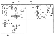
図12は、テレビ2に表示されるテレビ用ゲーム画像の一例を示す図である。図13は、端末装置7に表示される端末用ゲーム画像の一例を示す図である。   FIG. 12 is a diagram illustrating an example of a television game image displayed on the television 2. FIG. 13 is a diagram illustrating an example of a terminal game image displayed on the terminal device 7.

図12に示すように、テレビ2には、第1キャラクタ97、第2キャラクタ98a、第2キャラクタ98b、弓オブジェクト91、矢オブジェクト92、岩オブジェクト93、木オブジェクト94、剣オブジェクト96a、剣オブジェクト96b、および、敵キャラクタ99が表示される。   As shown in FIG. 12, the television 2 includes a first character 97, a second character 98a, a second character 98b, a bow object 91, an arrow object 92, a rock object 93, a tree object 94, a sword object 96a, and a sword object 96b. , And the enemy character 99 is displayed.

第1キャラクタ97は、ゲーム空間(仮想空間)に配置される仮想キャラクタであり、第1プレイヤによって操作される。第1キャラクタ97は、弓オブジェクト91および矢オブジェクト92を把持して、矢オブジェクト92をゲーム空間内に発射させて、敵キャラクタ99に対して攻撃を行う。また、第2キャラクタ98aは、ゲーム空間に配置される仮想キャラクタであり、第2プレイヤAによって操作される。第2キャラクタ98aは、剣オブジェクト96aを把持し、当該剣オブジェクト96aを用いて敵キャラクタ99に対して攻撃を行う。また、第2キャラクタ98bは、ゲーム空間に配置される仮想キャラクタであり、第2プレイヤBによって操作される。第2キャラクタ98bは、剣オブジェクト96bを把持し、当該剣オブジェクト96bを用いて敵キャラクタ99に対して攻撃を行う。敵キャラクタ99は、ゲーム装置3によって制御される仮想キャラクタである。本実施形態のゲームは、第1プレイヤ、第2プレイヤAおよび第2プレイヤBが互いに協力することによって、敵キャラクタ99を倒すことを目的とするゲームである。   The first character 97 is a virtual character placed in the game space (virtual space) and is operated by the first player. The first character 97 holds the bow object 91 and the arrow object 92, fires the arrow object 92 into the game space, and attacks the enemy character 99. The second character 98a is a virtual character placed in the game space and is operated by the second player A. The second character 98a holds the sword object 96a and attacks the enemy character 99 using the sword object 96a. The second character 98b is a virtual character placed in the game space and is operated by the second player B. The second character 98b holds the sword object 96b and attacks the enemy character 99 using the sword object 96b. The enemy character 99 is a virtual character controlled by the game apparatus 3. The game of this embodiment is a game aimed at defeating the enemy character 99 by the first player, the second player A, and the second player B cooperating with each other.

図12に示すように、テレビ2には、画面を上下左右に4等分した領域にそれぞれ異なる画像が表示される。具体的には、画面の左上の領域には、第1プレイヤが端末装置7を用いて操作する第1キャラクタ97の背後からゲーム空間を見た画像90aが表示される。具体的には、画像90aには、第1キャラクタ97、弓オブジェクト91、および矢オブジェクト92が含まれる。なお、本実施形態では、第1キャラクタ97が半透明で表示されるものとするが、第1キャラクタ97は表示されなくてもよい。画像90aは、ゲーム空間に設定された第1仮想カメラAでゲーム空間を撮像することによって取得される画像である。ゲーム空間の位置は、ゲーム空間に固定された直交座標系(xyz座標系)の各軸に関する座標値で表される。y軸はゲーム空間の地面に対して垂直上向きに設定され、x軸およびz軸は、ゲーム空間の地面と平行に設定される。第1キャラクタ97は、ゲーム空間の地面(xz平面)上を向き(xz平面に平行な向き)を変えながら移動する。第1キャラクタ97のゲーム空間における位置および向き(姿勢)は、所定の規則に従って変化される。なお、第1キャラクタ97の位置および姿勢は、第1プレイヤによる端末装置7に対する操作(例えば、左アナログスティック53Aに対する操作や十字ボタン54Aに対する操作)に応じて変化されてもよい。また、第1仮想カメラAのゲーム空間における位置は、第1キャラクタ97の位置に応じて定められ、第1仮想カメラAのゲーム空間における姿勢は、第1キャラクタ97の姿勢と端末装置7の姿勢とに応じて設定される。   As shown in FIG. 12, the television 2 displays different images in areas obtained by dividing the screen into four equal parts vertically and horizontally. Specifically, in the upper left area of the screen, an image 90a in which the game space is viewed from behind the first character 97 operated by the first player using the terminal device 7 is displayed. Specifically, the image 90a includes a first character 97, a bow object 91, and an arrow object 92. In the present embodiment, the first character 97 is displayed in a translucent manner, but the first character 97 may not be displayed. The image 90a is an image acquired by imaging the game space with the first virtual camera A set in the game space. The position of the game space is represented by coordinate values related to each axis of an orthogonal coordinate system (xyz coordinate system) fixed in the game space. The y axis is set vertically upward with respect to the ground of the game space, and the x axis and the z axis are set parallel to the ground of the game space. The first character 97 moves while changing its direction (direction parallel to the xz plane) on the ground (xz plane) of the game space. The position and orientation (posture) of the first character 97 in the game space are changed according to a predetermined rule. Note that the position and orientation of the first character 97 may be changed according to an operation on the terminal device 7 by the first player (for example, an operation on the left analog stick 53A or an operation on the cross button 54A). Further, the position of the first virtual camera A in the game space is determined according to the position of the first character 97, and the attitude of the first virtual camera A in the game space is the attitude of the first character 97 and the attitude of the terminal device 7. It is set according to.

また、画面の右上の領域には、第2プレイヤAがメインコントローラ8aを用いて操作する第2キャラクタ98aの背後からゲーム空間を見た画像90bが表示される。画像90bには、第2キャラクタ98aおよび剣オブジェクト96aが含まれる。なお、本実施形態では、第2キャラクタ98aが半透明で表示されるものとするが、第2キャラクタ98aは表示されなくてもよい。画像90bは、ゲーム空間に設定された第1仮想カメラBでゲーム空間を撮像することによって取得される画像である。第2キャラクタ98aは、ゲーム空間の地面上を向きを変えながら移動する。第2キャラクタ98aの位置および向き(姿勢)は、所定の規則に従って変化される。なお、第2キャラクタ98aの位置および姿勢は、第2プレイヤAによるメインコントローラ8aに対する操作(例えば、十字ボタン32aに対する操作、あるいは、サブコントローラ9が接続される場合にはアナログジョイスティック81に対する操作)に応じて変化されてもよい。また、第1仮想カメラBの位置および姿勢は、第2キャラクタ98aの位置および姿勢に応じて定められる。   In addition, in the upper right area of the screen, an image 90b of the game space viewed from behind the second character 98a operated by the second player A using the main controller 8a is displayed. The image 90b includes a second character 98a and a sword object 96a. In the present embodiment, the second character 98a is displayed in a translucent manner, but the second character 98a may not be displayed. The image 90b is an image acquired by imaging the game space with the first virtual camera B set in the game space. The second character 98a moves on the ground of the game space while changing its direction. The position and orientation (posture) of the second character 98a are changed according to a predetermined rule. The position and posture of the second character 98a are determined by the operation of the second player A on the main controller 8a (for example, operation on the cross button 32a or operation on the analog joystick 81 when the sub controller 9 is connected). It may be changed accordingly. Further, the position and posture of the first virtual camera B are determined according to the position and posture of the second character 98a.

また、画面の左下の領域には、第2プレイヤBがメインコントローラ8bを用いて操作する第2キャラクタ98bの背後からゲーム空間を見た画像90cが表示される。画像90cには、第2キャラクタ98bおよび剣オブジェクト96bが含まれる。なお、本実施形態では、第2キャラクタ98bが半透明で表示されるものとするが、第2キャラクタ98bは表示されなくてもよい。画像90cは、ゲーム空間に設定された第1仮想カメラCによってゲーム空間を撮像することによって取得される画像である。第2キャラクタ98bは、ゲーム空間の地面上を向きを変えながら移動する。第2キャラクタ98bの位置および向き(姿勢)は、所定の規則に従って変化される。なお、第2キャラクタ98bの位置および姿勢は、第2プレイヤBによるメインコントローラ8bに対する操作(例えば、十字ボタン32a等に対する操作)に応じて変化されてもよい。また、第1仮想カメラCの位置および姿勢は、第2キャラクタ98bの位置および姿勢に応じて定められる。なお、画面の右下の領域には何も表示されないが、第2プレイヤが3人の場合には、画面の右下の領域にも画像が表示される。   In the lower left area of the screen, an image 90c of the game space viewed from behind the second character 98b operated by the second player B using the main controller 8b is displayed. The image 90c includes a second character 98b and a sword object 96b. In the present embodiment, the second character 98b is displayed in a translucent manner, but the second character 98b may not be displayed. The image 90c is an image acquired by imaging the game space with the first virtual camera C set in the game space. The second character 98b moves while changing its direction on the ground of the game space. The position and orientation (posture) of the second character 98b are changed according to a predetermined rule. Note that the position and orientation of the second character 98b may be changed according to an operation on the main controller 8b by the second player B (for example, an operation on the cross button 32a or the like). Further, the position and posture of the first virtual camera C are determined according to the position and posture of the second character 98b. Note that nothing is displayed in the lower right area of the screen, but when there are three second players, an image is also displayed in the lower right area of the screen.

なお、各仮想カメラ(第1仮想カメラA〜C)は、各プレイヤキャラクタ(97、98a、98b)の背後の所定位置に設定されるが、各仮想カメラは各プレイヤキャラクタの視点と一致するように設定されてもよい。   Each virtual camera (first virtual camera A to C) is set at a predetermined position behind each player character (97, 98a, 98b), but each virtual camera matches the viewpoint of each player character. May be set.

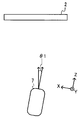
一方、図13に示すように、端末装置7には弓オブジェクト91および矢オブジェクト92を含む画像90eが表示される。画像90eは、ゲーム空間に配置された第2仮想カメラによってゲーム空間を撮像することによって取得される画像である。具体的には、図13に示す画像90eは、弓オブジェクト91および矢オブジェクト92をゲーム空間の上方から見た画像である。第2仮想カメラは弓オブジェクト91に固定されており、第2仮想カメラのゲーム空間における位置および姿勢は、弓オブジェクト91の位置および姿勢に応じて定められる。   On the other hand, as shown in FIG. 13, the terminal device 7 displays an image 90 e including a bow object 91 and an arrow object 92. The image 90e is an image acquired by imaging the game space with the second virtual camera arranged in the game space. Specifically, an image 90e shown in FIG. 13 is an image of the bow object 91 and the arrow object 92 viewed from above the game space. The second virtual camera is fixed to the bow object 91, and the position and posture of the second virtual camera in the game space are determined according to the position and posture of the bow object 91.

上述のように、第1プレイヤは端末装置7を操作することによって、第1キャラクタ97に矢オブジェクト92をゲーム空間に発射させることにより、敵キャラクタ99に対して攻撃を行う。具体的には、第1プレイヤは、端末装置7の姿勢を基準姿勢から変化させることで矢オブジェクト92の発射方向、および第1仮想カメラAの撮像方向を変化させ、端末装置7のタッチパネル52に対するタッチ操作を行うことで、矢オブジェクト92を発射させる。   As described above, the first player attacks the enemy character 99 by operating the terminal device 7 to cause the first character 97 to fire the arrow object 92 into the game space. Specifically, the first player changes the firing direction of the arrow object 92 and the imaging direction of the first virtual camera A by changing the posture of the terminal device 7 from the reference posture, and the touch panel 52 of the terminal device 7 is touched. The arrow object 92 is fired by performing a touch operation.

図14は、本実施形態におけるゲームを実行する際の端末装置7の基準姿勢を示す図である。ここで、「基準姿勢」は、例えば、端末装置7のLCD51の画面が地面と水平であって、かつ、端末装置7の右側面(図9(c))がテレビ2を向く姿勢である。すなわち、基準姿勢は、端末装置7を基準としたXYZ座標系のY軸方向(LCD51の外向きの法線方向)が実空間の上方向と一致し、かつ、Z軸(端末装置7の長辺方向と平行な軸)がテレビ2の画面の中心(あるいは画像90aの中心)に向かう姿勢である。   FIG. 14 is a diagram illustrating the reference posture of the terminal device 7 when executing the game in the present embodiment. Here, the “reference posture” is, for example, a posture in which the screen of the LCD 51 of the terminal device 7 is horizontal with the ground, and the right side surface (FIG. 9C) of the terminal device 7 faces the television 2. In other words, the reference orientation is such that the Y-axis direction (the outward normal direction of the LCD 51) of the XYZ coordinate system with respect to the terminal device 7 coincides with the upward direction of the real space, and the Z-axis (the length of the terminal device 7). In this posture, the axis parallel to the side direction is directed toward the center of the screen of the television 2 (or the center of the image 90a).

図14に示すように、初期的には、端末装置7は、基準姿勢で第1プレイヤによって把持され、第1プレイヤはテレビ2に表示されたゲーム画像を見ながら、端末装置7をテレビ2の方向に向けるとともに、端末装置7のタッチパネル52に対するタッチ操作を行う。第1プレイヤは、端末装置7を基準姿勢から他の姿勢へと変化させることによって、矢オブジェクト92の発射方向(移動方向)を制御し、タッチパネル52に対してタッチ操作を行うことによって、矢オブジェクト92を発射方向に発射させる。   As shown in FIG. 14, initially, the terminal device 7 is held by the first player in the reference posture, and the first player holds the terminal device 7 on the television 2 while watching the game image displayed on the television 2. In addition, the touch operation on the touch panel 52 of the terminal device 7 is performed. The first player controls the firing direction (movement direction) of the arrow object 92 by changing the terminal device 7 from the reference posture to another posture, and performs a touch operation on the touch panel 52 to thereby move the arrow object. 92 is fired in the firing direction.

図15は、第1プレイヤによって行われるタッチパネル52に対するタッチ操作の一例を示す図である。なお、図15においては、弓オブジェクト91および矢オブジェクト92の表示が省略されている。図15に示すように、第1プレイヤは、自身の指でタッチパネル52上の位置にタッチオン操作を行う。ここで、タッチオン操作とは、タッチパネル52に指が接触していない場合において、タッチパネル52に指を接触させる操作である。タッチオンが行われた位置をタッチオン位置という。次に、第1プレイヤは、指をタッチパネル52に接触させたまま、図15の矢印の方向(テレビ2に向かう方向と反対方向;Z軸負方向)に指をスライドさせる。そして、第1プレイヤは、タッチパネル52に対してタッチオフ操作を行う。ここで、タッチオフ操作とは、タッチパネル52に指が接触している場合において、指をタッチパネル52から離す(リリースする)操作である。タッチオフが行われた位置をタッチオフ位置という。このような第1プレイヤによるタッチパネル52に対するスライド操作に応じて、テレビ2の左上の領域に表示される画像90aは変化する。   FIG. 15 is a diagram illustrating an example of a touch operation on the touch panel 52 performed by the first player. In FIG. 15, the display of the bow object 91 and the arrow object 92 is omitted. As shown in FIG. 15, the first player performs a touch-on operation at a position on the touch panel 52 with his / her finger. Here, the touch-on operation is an operation of bringing a finger into contact with the touch panel 52 when the finger is not in contact with the touch panel 52. The position where the touch-on is performed is called a touch-on position. Next, the first player slides the finger in the direction of the arrow in FIG. 15 (the direction opposite to the direction toward the television 2; the Z-axis negative direction) while keeping the finger in contact with the touch panel 52. Then, the first player performs a touch-off operation on the touch panel 52. Here, the touch-off operation is an operation of releasing (releasing) the finger from the touch panel 52 when the finger is in contact with the touch panel 52. The position where the touch-off is performed is called a touch-off position. The image 90a displayed in the upper left area of the television 2 changes according to such a slide operation on the touch panel 52 by the first player.

図16Aは、第1プレイヤがタッチパネル52に対するタッチ操作を行った場合において、第1プレイヤの指がタッチオン位置とタッチオフ位置との間に位置するときのテレビ2の左上の領域に表示される画像90aを示す図である。図16Bは、第1プレイヤがタッチパネル52に対するタッチ操作を行った場合において、第1プレイヤの指がタッチオフ位置に位置するときのテレビ2の左上の領域に表示される画像90aを示す図である。なお、図16Aおよび図16Bにおいては、第1キャラクタ97の表示は省略されている。   FIG. 16A shows an image 90a displayed in the upper left area of the television 2 when the finger of the first player is located between the touch-on position and the touch-off position when the first player performs a touch operation on the touch panel 52. FIG. FIG. 16B is a diagram illustrating an image 90a displayed in the upper left area of the television 2 when the finger of the first player is located at the touch-off position when the first player performs a touch operation on the touch panel 52. In FIG. 16A and FIG. 16B, the display of the first character 97 is omitted.

図16Aに示すように、第1プレイヤが自身の指をタッチパネル52に接触させると、画像90aには、照準95(照準オブジェクト95)が表示される。照準95は円形状であり、当該円の中心は矢オブジェクト92がゲーム空間に発射された場合の矢オブジェクト92が飛んでいく位置(到達目標の位置)を示す。図16Aおよび図16Bに示す例では、照準95の中心は敵キャラクタ99上に位置し、この状態で矢オブジェクト92が発射されると、矢オブジェクト92は敵キャラクタ99に刺さる。なお、矢オブジェクト92は、照準95の中心に必ずしも到達することはなく、他の要因(例えば、重力や風等の影響)によって、実際の到達位置は照準95の中心からずれる場合もある。また、照準95の形状は円形状に限らず、どのような形状(四角や三角、あるいは点)でもよい。   As shown in FIG. 16A, when the first player makes his / her finger touch the touch panel 52, an aim 95 (an aim object 95) is displayed on the image 90a. The aim 95 has a circular shape, and the center of the circle indicates a position where the arrow object 92 flies when the arrow object 92 is fired into the game space (position of the reaching target). In the example shown in FIGS. 16A and 16B, the center of the aim 95 is located on the enemy character 99, and when the arrow object 92 is fired in this state, the arrow object 92 stabs the enemy character 99. Note that the arrow object 92 does not necessarily reach the center of the aim 95, and the actual arrival position may deviate from the center of the aim 95 due to other factors (for example, the influence of gravity or wind). Further, the shape of the aim 95 is not limited to a circular shape, but may be any shape (square, triangle, or point).

また、第1プレイヤが自身の指をタッチパネル52に接触させたまま図15の矢印の方向に移動させると、当該指の移動距離に応じて第1仮想カメラAのズーム設定が変化する。具体的には、図16Aに示すように、第1プレイヤの指がタッチオン位置とタッチオフ位置との間に位置する場合(図15参照)、第1仮想カメラAはズームインされて、図16Aに示す画像90aは、図12に示す画像90aよりもゲーム空間の一部を拡大した画像となる。さらに、図16Bに示すように、第1プレイヤが指をタッチオフ位置までスライドさせると、図16Bに示す画像90aはゲーム空間の一部をさらに拡大した画像となる。なお、画像90aはテレビ2を4等分に分割した場合の左上の領域に表示される画像であり、上記移動距離に応じて画像90a自体の大きさは変化しない。   When the first player moves his / her finger in the direction of the arrow in FIG. 15 while keeping his / her finger in contact with the touch panel 52, the zoom setting of the first virtual camera A changes according to the moving distance of the finger. Specifically, as shown in FIG. 16A, when the first player's finger is located between the touch-on position and the touch-off position (see FIG. 15), the first virtual camera A is zoomed in and shown in FIG. 16A. The image 90a is an image obtained by enlarging a part of the game space as compared with the image 90a shown in FIG. Further, as shown in FIG. 16B, when the first player slides his / her finger to the touch-off position, the image 90a shown in FIG. 16B becomes an image obtained by further enlarging a part of the game space. The image 90a is an image displayed in the upper left area when the television 2 is divided into four equal parts, and the size of the image 90a itself does not change according to the movement distance.

また、図16Aおよび図16Bに示すように、第1プレイヤによるタッチ操作に応じて、弓オブジェクト91および矢オブジェクト92の表示も変化する。具体的には、上記指の移動距離が長いほど矢オブジェクト92が手前側に引かれるように表示される。   Further, as shown in FIGS. 16A and 16B, the display of the bow object 91 and the arrow object 92 also changes in response to the touch operation by the first player. Specifically, the arrow object 92 is displayed so as to be pulled toward the near side as the moving distance of the finger increases.

第1プレイヤの指がタッチパネル52から離れると、矢オブジェクト92が発射され、矢オブジェクト92がゲーム空間を飛んでいく様子がテレビ2に表示される。具体的には、矢オブジェクト92は、現在の矢オブジェクト92の位置から照準95によって示される画像90a上の位置に対応する、ゲーム空間内の位置に向かって発射されてゲーム空間内を飛んでいく。   When the finger of the first player leaves the touch panel 52, the arrow object 92 is fired, and the state in which the arrow object 92 flies through the game space is displayed on the television 2. Specifically, the arrow object 92 is fired from the current position of the arrow object 92 toward the position in the game space corresponding to the position on the image 90a indicated by the aim 95, and flies through the game space. .

次に、第1プレイヤが端末装置7の姿勢を変化させた場合について、説明する。図17は、図16Aに示す画像90aがテレビ2に表示されている場合において、基準姿勢からY軸周りに角度θ1だけ回転させたときの端末装置7を、実空間の上方から見た図である。図18は、図16Aに示す画像90aがテレビ2に表示されている場合において、端末装置7を基準姿勢からY軸周りに角度θ1だけさせたときに、テレビ2の左上の領域に表示される画像90aの一例を示す図である。   Next, a case where the first player changes the attitude of the terminal device 7 will be described. FIG. 17 is a view of the terminal device 7 as viewed from above the real space when the image 90a shown in FIG. 16A is displayed on the television 2 and rotated from the reference posture by the angle θ1 around the Y axis. is there. FIG. 18 is displayed in the upper left area of the television 2 when the terminal device 7 is moved by the angle θ1 around the Y axis from the reference posture when the image 90a shown in FIG. It is a figure which shows an example of the image 90a.

図17および図18に示すように、端末装置7を基準姿勢からY軸周りに角度θ1だけ回転させると、図16Aに示す場合よりも右側のゲーム空間を撮像した画像90aが、テレビ2に表示される。すなわち、端末装置7のZ軸をテレビ2の画面の中心(あるいは画像90aの中心)よりも右側の位置に向けるように端末装置7の姿勢を変化させると、ゲーム空間の第1仮想カメラAの姿勢も同様に変化して、第1仮想カメラAによって撮像される画像90aは変化する。   As shown in FIGS. 17 and 18, when the terminal device 7 is rotated from the reference posture by the angle θ1 around the Y axis, an image 90a obtained by imaging the game space on the right side of the case shown in FIG. Is done. That is, when the attitude of the terminal device 7 is changed so that the Z axis of the terminal device 7 is directed to the right side of the center of the screen of the television 2 (or the center of the image 90a), the first virtual camera A in the game space is changed. The posture also changes in the same manner, and the image 90a captured by the first virtual camera A changes.

具体的には、端末装置7を基準姿勢からY軸周りに角度θ1だけ回転させると、第1仮想カメラAの撮像方向(第1仮想カメラAを基準とした座標系におけるCZ軸方向)がゲーム空間の垂直上向きの軸(y軸)周りに回転する。図19は、端末装置7をY軸周りに角度θ1だけ回転させた場合の第1仮想カメラAを上方から見た図である。図19において、軸CZは、端末装置7が基準姿勢であるときの第1仮想カメラAの撮像方向を示し、軸CZ’は、端末装置7がY軸周りに角度θ1だけ回転されたときの第1仮想カメラAの撮像方向を示す。図19に示すように、端末装置7がY軸周りに角度θ1だけ回転されると、第1仮想カメラAは、y軸周りに角度θ2(>θ1)だけ回転される。すなわち、端末装置7の姿勢の変化量よりも、第1仮想カメラAの姿勢の変化量の方が大きくなるように、第1仮想カメラAの姿勢が変化される。このため、例えば、第1プレイヤが現在表示されていない第1キャラクタ97の右側のゲーム空間を表示させるために、第1仮想カメラAを90度回転させようとする場合、端末装置7を90度Y軸周りに回転させる必要はない。この場合、例えば、第1プレイヤは端末装置7をY軸周りに45度だけ回転させることで、第1仮想カメラAを90度回転させて、現在表示されていない第1キャラクタ97の右側のゲーム空間を表示させることができる。これにより、第1プレイヤが向く方向がテレビ2の画面を向く方向から大きくずれることなく、第1プレイヤは第1仮想カメラAを大きく回転させて現在表示されているゲーム空間の領域とは異なる領域をテレビ2に表示させることができる。従って、第1プレイヤはテレビ2の画面を見ながらゲームを楽しむことができる。   Specifically, when the terminal device 7 is rotated from the reference posture around the Y axis by an angle θ1, the imaging direction of the first virtual camera A (CZ axis direction in the coordinate system with reference to the first virtual camera A) is the game. Rotate around the vertical upward axis of space (y-axis). FIG. 19 is a view of the first virtual camera A as viewed from above when the terminal device 7 is rotated about the Y axis by an angle θ1. In FIG. 19, the axis CZ indicates the imaging direction of the first virtual camera A when the terminal device 7 is in the reference posture, and the axis CZ ′ is when the terminal device 7 is rotated about the Y axis by an angle θ1. The imaging direction of the first virtual camera A is shown. As shown in FIG. 19, when the terminal device 7 is rotated about the Y axis by an angle θ1, the first virtual camera A is rotated about the y axis by an angle θ2 (> θ1). That is, the posture of the first virtual camera A is changed so that the amount of change in the posture of the first virtual camera A is larger than the amount of change in the posture of the terminal device 7. Therefore, for example, when the first virtual camera A is to be rotated 90 degrees in order to display the game space on the right side of the first character 97 that is not currently displayed, the terminal device 7 is set to 90 degrees. There is no need to rotate around the Y axis. In this case, for example, the first player rotates the terminal device 7 by 45 degrees around the Y axis, thereby rotating the first virtual camera A by 90 degrees and playing the game on the right side of the first character 97 that is not currently displayed. Space can be displayed. Thereby, the first player turns the first virtual camera A greatly and the area different from the area of the game space currently displayed without greatly deviating from the direction facing the screen of the television 2. Can be displayed on the television 2. Therefore, the first player can enjoy the game while watching the screen of the television 2.

また、図18に示すように、端末装置7の姿勢の変化に応じて、照準95の位置も変化する。具体的には、端末装置7が基準姿勢である場合には照準95は画像90aの中心に位置するが、端末装置7を基準姿勢からY軸周りに角度θ1だけ回転させると、照準95も画像90aの中心よりも右側に移動する。端末装置7をY軸周りにさらに回転させると、第1仮想カメラAはさらに回転して、照準95もさらに右方向に移動する。端末装置7をY軸周りに所定の閾値まで回転させると、第1仮想カメラAのy軸周りの回転角は当該所定の閾値に応じた値まで変化するとともに、照準95は画像90aの右端に移動する。しかしながら、端末装置7をY軸周りに所定の閾値を超えて回転させても、第1仮想カメラAのy軸周りの回転角はそれ以上大きくならず、照準95の位置もそれ以上移動しない。これにより、端末装置7のZ軸がテレビ2を向く方向から大きく外れるように第1プレイヤが端末装置7を操作してしまうことが減り、操作しやすくなる。   Also, as shown in FIG. 18, the position of the aim 95 also changes according to the change in the attitude of the terminal device 7. Specifically, when the terminal device 7 is in the reference posture, the aim 95 is positioned at the center of the image 90a. Move to the right from the center of 90a. When the terminal device 7 is further rotated around the Y axis, the first virtual camera A further rotates, and the aim 95 further moves in the right direction. When the terminal device 7 is rotated around the Y axis to a predetermined threshold, the rotation angle around the y axis of the first virtual camera A changes to a value corresponding to the predetermined threshold, and the aim 95 is at the right end of the image 90a. Moving. However, even if the terminal device 7 is rotated around the Y axis beyond a predetermined threshold, the rotation angle around the y axis of the first virtual camera A does not increase any more, and the position of the aim 95 does not move any further. Accordingly, the first player is less likely to operate the terminal device 7 so that the Z axis of the terminal device 7 is greatly deviated from the direction facing the television 2, and the operation becomes easier.

以上のように、端末装置7の姿勢に応じて矢オブジェクト92の発射方向が決定され、タッチパネル52に対するタッチ操作に応じて矢オブジェクト92が発射される。   As described above, the firing direction of the arrow object 92 is determined according to the attitude of the terminal device 7, and the arrow object 92 is fired according to the touch operation on the touch panel 52.

なお、第2プレイヤは、メインコントローラ8を振ることによって、自身によって操作される第2キャラクタに剣オブジェクト96を振らせ、敵キャラクタ99に対して攻撃を行う。第2キャラクタが把持する剣オブジェクト96の姿勢は、メインコントローラ8の姿勢の変化に応じて変化する。例えば、メインコントローラ8bのZ1軸(図3参照)が重力方向と反対方向となるようにメインコントローラ8bが把持されている場合、剣オブジェクト96bはゲーム空間のy軸方向を向く。この場合、図12に示すように、第2キャラクタ98bが剣オブジェクト96bを真上に振り上げている様子が表示される。なお、剣オブジェクト96は、メインコントローラ8の姿勢に限らず、メインコントローラ8の操作ボタンに対する操作に応じて制御されてもよい。   The second player swings the main controller 8 to cause the second character operated by the second player to swing the sword object 96 and attack the enemy character 99. The posture of the sword object 96 held by the second character changes according to the change in the posture of the main controller 8. For example, when the main controller 8b is gripped so that the Z1 axis (see FIG. 3) of the main controller 8b is opposite to the direction of gravity, the sword object 96b faces the y-axis direction of the game space. In this case, as shown in FIG. 12, a state in which the second character 98b swings up the sword object 96b is displayed. Note that the sword object 96 is not limited to the posture of the main controller 8 and may be controlled in accordance with an operation on the operation button of the main controller 8.

[6.ゲーム処理の詳細]
次に、本ゲームシステムにおいて実行されるゲーム処理の詳細を説明する。まず、ゲーム処理において用いられる各種データについて説明する。図20は、ゲーム処理において用いられる各種データを示す図である。図20において、ゲーム装置3のメインメモリ(外部メインメモリ12または内部メインメモリ11e)に記憶される主なデータを示す図である。図20に示すように、ゲーム装置3のメインメモリには、ゲームプログラム100、コントローラ操作データ110、端末操作データ120、および処理用データ130が記憶される。なお、メインメモリには、図20に示すデータの他、ゲームに登場する各種オブジェクトの画像データやゲームに使用される音声データ等、ゲームに必要なデータが記憶される。
[6. Details of game processing]
Next, details of the game process executed in this game system will be described. First, various data used in the game process will be described. FIG. 20 is a diagram showing various data used in the game process. In FIG. 20, it is a figure which shows the main data memorize | stored in the main memory (the external main memory 12 or the internal main memory 11e) of the game device 3. As shown in FIG. 20, a game program 100, controller operation data 110, terminal operation data 120, and processing data 130 are stored in the main memory of the game apparatus 3. In addition to the data shown in FIG. 20, the main memory stores data necessary for the game such as image data of various objects appearing in the game and sound data used in the game.

ゲームプログラム100は、ゲーム装置3に電源が投入された後の適宜のタイミングで光ディスク4からその一部または全部が読み込まれてメインメモリに記憶される。なお、ゲームプログラム100は、光ディスク4に代えて、フラッシュメモリ17やゲーム装置3の外部装置から(例えばインターネットを介して)取得されてもよい。また、ゲームプログラム100に含まれる一部(例えば、メインコントローラ8および/または端末装置7の姿勢を算出するためのプログラム)については、ゲーム装置3内に予め記憶されていてもよい。   A part or all of the game program 100 is read from the optical disk 4 and stored in the main memory at an appropriate timing after the game apparatus 3 is turned on. The game program 100 may be obtained from the flash memory 17 or an external device of the game device 3 (for example, via the Internet) instead of the optical disc 4. Further, a part of the game program 100 (for example, a program for calculating the attitude of the main controller 8 and / or the terminal device 7) may be stored in advance in the game apparatus 3.

コントローラ操作データ110は、メインコントローラ8に対するユーザ(第2プレイヤ)の操作を表すデータであり、メインコントローラ8に対する操作に基づいてメインコントローラ8から出力(送信)される。コントローラ操作データ110は、メインコントローラ8から送信されてゲーム装置3において取得され、メインメモリに記憶される。コントローラ操作データ110は、角速度データ111、メイン操作ボタンデータ112、加速度データ113を含む。なお、コントローラ操作データ110は、これらのデータの他、メインコントローラ8の画像処理回路41によって算出される座標を示すマーカ座標データ等を含む。また、ゲーム装置3は、複数のメインコントローラ8(具体的には、メインコントローラ8aおよび8b)から操作データを取得するため、各メインコントローラ8からそれぞれ送信されてくる各コントローラ操作データ110をメインメモリにそれぞれ記憶する。最新の(最後に取得された)データから所定個数のコントローラ操作データ110が、メインコントローラ8毎に、時系列に記憶されてもよい。   The controller operation data 110 is data representing a user (second player) operation on the main controller 8 and is output (transmitted) from the main controller 8 based on the operation on the main controller 8. The controller operation data 110 is transmitted from the main controller 8, acquired by the game apparatus 3, and stored in the main memory. The controller operation data 110 includes angular velocity data 111, main operation button data 112, and acceleration data 113. The controller operation data 110 includes, in addition to these data, marker coordinate data indicating coordinates calculated by the image processing circuit 41 of the main controller 8. In addition, since the game apparatus 3 acquires operation data from a plurality of main controllers 8 (specifically, main controllers 8a and 8b), the controller operation data 110 transmitted from each main controller 8 is stored in the main memory. Remember each. A predetermined number of controller operation data 110 from the latest (last acquired) data may be stored in time series for each main controller 8.

角速度データ111は、メインコントローラ8におけるジャイロセンサ48によって検出された角速度を表すデータである。ここでは、角速度データ111は、メインコントローラ8に固定のX1Y1Z1座標系(図3参照)の各軸回りの角速度をそれぞれ表すものであるが、他の実施形態においては、任意の1軸以上の軸回り角速度を表すものであればよい。このように、本実施形態においては、メインコントローラ8がジャイロセンサ48を備え、コントローラ操作データ110には、メインコントローラ8の姿勢を算出するための物理量として上記角速度データ111が含まれる。したがって、ゲーム装置3は、メインコントローラ8の姿勢を角速度に基づいて正確に算出することができる。具体的には、ゲーム装置3は、ジャイロセンサ48によって検出されたX1軸、Y1軸、Z1軸周りの角速度をそれぞれ時間で積分することによって、初期的な姿勢からのX1Y1Z1座標系の各軸周りの回転角を算出することができる。 The angular velocity data 111 is data representing the angular velocity detected by the gyro sensor 48 in the main controller 8. Here, the angular velocity data 111 represents the angular velocity around each axis of the X1Y1Z1 coordinate system (see FIG. 3) fixed to the main controller 8, but in other embodiments, any one or more axes Any device that expresses the rotational angular velocity may be used. As described above, in this embodiment, the main controller 8 includes the gyro sensor 48, and the controller operation data 110 includes the angular velocity data 111 as a physical quantity for calculating the attitude of the main controller 8. Therefore, the game apparatus 3 can accurately calculate the attitude of the main controller 8 based on the angular velocity. Specifically, the game apparatus 3 integrates the angular velocities around the X1 axis, the Y1 axis, and the Z1 axis detected by the gyro sensor 48 with respect to time, so that each of the axes of the X1Y1Z1 coordinate system from the initial posture is rotated. The rotation angle can be calculated.

メイン操作ボタンデータ112は、メインコントローラ8に設けられた各操作ボタン32a〜32iに対する入力状態を表すデータである。具体的には、メイン操作ボタンデータ112は、各操作ボタン32a〜32iが押下されているか否かを表す。   The main operation button data 112 is data representing an input state with respect to the operation buttons 32 a to 32 i provided in the main controller 8. Specifically, the main operation button data 112 represents whether or not each of the operation buttons 32a to 32i is pressed.

加速度データ113は、メインコントローラ8の加速度センサ37によって検出された加速度を表すデータである。ここでは、加速度データ113は、メインコントローラ8に固定のX1Y1Z1座標系の各軸周りの加速度をそれぞれ表す。   The acceleration data 113 is data representing the acceleration detected by the acceleration sensor 37 of the main controller 8. Here, the acceleration data 113 represents the acceleration around each axis of the X1Y1Z1 coordinate system fixed to the main controller 8.

なお、コントローラ操作データ110は、サブコントローラ9に対するプレイヤの操作を表すデータを含んでもよい。   The controller operation data 110 may include data representing the player's operation on the sub-controller 9.

端末操作データ120は、端末装置7に対するユーザ(第1プレイヤ)の操作を表すデータであり、端末装置7に対する操作に基づいて端末装置7から出力(送信)される。端末操作データ120は、端末装置7から送信されてゲーム装置3において取得され、メインメモリに記憶される。端末操作データ120は、角速度データ121、タッチ位置データ122、操作ボタンデータ123、および加速度データ124を含む。なお、端末操作データ120は、これらのデータの他、端末装置7の磁気センサ62によって検出された方位を示す方位データデータ等を含む。また、ゲーム装置3は、複数の端末装置7から端末操作データを取得する場合、各端末装置7からそれぞれ送信されてくる各端末操作データ120をメインメモリにそれぞれ記憶してもよい。   The terminal operation data 120 is data representing a user (first player) operation on the terminal device 7 and is output (transmitted) from the terminal device 7 based on the operation on the terminal device 7. The terminal operation data 120 is transmitted from the terminal device 7, acquired by the game device 3, and stored in the main memory. The terminal operation data 120 includes angular velocity data 121, touch position data 122, operation button data 123, and acceleration data 124. The terminal operation data 120 includes azimuth data data indicating the azimuth detected by the magnetic sensor 62 of the terminal device 7 in addition to these data. In addition, when the game apparatus 3 acquires terminal operation data from a plurality of terminal apparatuses 7, each terminal operation data 120 transmitted from each terminal apparatus 7 may be stored in the main memory.

角速度データ121は、端末装置7におけるジャイロセンサ64によって検出された角速度を表すデータである。ここでは、角速度データ121は、端末装置7に固定のXYZ座標系(図9参照)の各軸回りの角速度をそれぞれ表すものであるが、他の実施形態においては、任意の1軸以上の軸回り角速度を表すものであればよい。   The angular velocity data 121 is data representing the angular velocity detected by the gyro sensor 64 in the terminal device 7. Here, the angular velocity data 121 represents the angular velocity around each axis of the XYZ coordinate system (see FIG. 9) fixed to the terminal device 7, but in one or more other axes in other embodiments. Any device that expresses the rotational angular velocity may be used.

タッチ位置データ122は、端末装置7のタッチパネル52においてタッチが行われた位置(タッチ位置)の座標を示すデータである。タッチ位置データ122は、最新のタッチ位置の座標を示すデータに加えて、過去所定期間において検出されたタッチ位置の座標を示すデータが含まれる。なお、タッチパネル52がタッチ位置を検出した場合は、タッチ位置の座標値は予め定められた範囲となり、タッチパネル52がタッチ位置を検出しない場合は、タッチ位置の座標値は当該範囲外の所定の値となる。   The touch position data 122 is data indicating the coordinates of the position (touch position) where the touch is performed on the touch panel 52 of the terminal device 7. The touch position data 122 includes data indicating the coordinates of the touch position detected in the past predetermined period in addition to the data indicating the coordinates of the latest touch position. When the touch panel 52 detects the touch position, the coordinate value of the touch position is in a predetermined range. When the touch panel 52 does not detect the touch position, the coordinate value of the touch position is a predetermined value outside the range. It becomes.

操作ボタンデータ123は、端末装置7に設けられた各操作ボタン54A〜54Lに対する入力状態を表すデータである。具体的には、操作ボタンデータ123は、各操作ボタン54A〜54Lが押下されているか否かを表す。   The operation button data 123 is data representing an input state for each of the operation buttons 54 </ b> A to 54 </ b> L provided on the terminal device 7. Specifically, the operation button data 123 represents whether or not each of the operation buttons 54A to 54L is pressed.

加速度データ124は、端末装置7の加速度センサ63によって検出された加速度を表すデータである。ここでは、端末装置7に固定のXYZ座標系(図9参照)の各軸回りの加速度をそれぞれ表す。   The acceleration data 124 is data representing the acceleration detected by the acceleration sensor 63 of the terminal device 7. Here, the acceleration around each axis of the XYZ coordinate system (see FIG. 9) fixed to the terminal device 7 is represented.

処理用データ130は、後述するゲーム処理(図21)において用いられるデータである。処理用データ130は、端末姿勢データ131、キャラクタデータ132、照準データ133、弓データ134、矢データ135、目標位置データ136、第1仮想カメラAデータ137、第1仮想カメラBデータ138、第1仮想カメラCデータ139、および、第2仮想カメラデータ140を含む。なお、図20に示すデータの他、処理用データ130は、ゲームに登場する各種オブジェクトに設定される各種パラメータを表すデータ等、ゲーム処理において用いられる各種データを含む。   The processing data 130 is data used in a game process (FIG. 21) described later. The processing data 130 includes terminal attitude data 131, character data 132, aiming data 133, bow data 134, arrow data 135, target position data 136, first virtual camera A data 137, first virtual camera B data 138, first data Virtual camera C data 139 and second virtual camera data 140 are included. In addition to the data shown in FIG. 20, the processing data 130 includes various data used in the game process, such as data representing various parameters set for various objects appearing in the game.

端末姿勢データ131は、端末装置7の姿勢を表すデータである。端末装置7の姿勢は、例えば、上記基準姿勢から現在の姿勢への回転を表す回転行列によって表現されてもよいし、3つの角度によって表現されてもよい。端末姿勢データ131は、端末装置7からの端末操作データ120に含まれる角速度データ121に基づいて算出される。具体的には、端末姿勢データ131は、ジャイロセンサ64によって検出されたX軸、Y軸、Z軸周りの角速度をそれぞれ時間で積分することによって算出される。なお、端末装置7の姿勢は、ジャイロセンサ64によって検出された角速度を示す角速度データ121に限らず、加速度センサ63によって検出された加速度を表す加速度データ124、および、磁気センサ62によって検出された方位を示す方位データに基づいて算出されてもよい。また、角速度に基づいて算出される姿勢を加速度データや方位データに基づいて補正をすることによって姿勢を算出するようにしてもよい。   The terminal attitude data 131 is data representing the attitude of the terminal device 7. The attitude of the terminal device 7 may be expressed by, for example, a rotation matrix representing rotation from the reference attitude to the current attitude, or may be expressed by three angles. The terminal attitude data 131 is calculated based on the angular velocity data 121 included in the terminal operation data 120 from the terminal device 7. Specifically, the terminal attitude data 131 is calculated by integrating the angular velocities around the X, Y, and Z axes detected by the gyro sensor 64 with time. Note that the attitude of the terminal device 7 is not limited to the angular velocity data 121 indicating the angular velocity detected by the gyro sensor 64, but the acceleration data 124 indicating the acceleration detected by the acceleration sensor 63 and the azimuth detected by the magnetic sensor 62. It may be calculated based on the azimuth data indicating. Further, the posture may be calculated by correcting the posture calculated based on the angular velocity based on the acceleration data or the azimuth data.

キャラクタデータ132は、各キャラクタのゲーム空間における位置および姿勢を表すデータである。具体的には、キャラクタデータ132は、第1キャラクタ97の位置および姿勢を表すデータ、第2キャラクタ98aの位置および姿勢を表すデータ、および、第2キャラクタ98bの位置および姿勢を表すデータを含む。   The character data 132 is data representing the position and posture of each character in the game space. Specifically, the character data 132 includes data representing the position and posture of the first character 97, data representing the position and posture of the second character 98a, and data representing the position and posture of the second character 98b.

照準データ133は、照準95の位置を示すデータ、および、照準95を画面に表示するか否かを示すフラグを含む。照準95の位置は、テレビ2の左上の領域に表示される画像90a上の位置であり、画像90aの中心を原点として右方向にs軸、上方向にt軸が設定されるst座標系の座標値で表される。   The aiming data 133 includes data indicating the position of the aiming 95 and a flag indicating whether or not to display the aiming 95 on the screen. The position of the aim 95 is a position on the image 90a displayed in the upper left area of the television 2, and the st coordinate system in which the s axis is set to the right and the t axis is set to the upper side with the center of the image 90a as the origin. Expressed as coordinate values.

弓データ134は、弓オブジェクト91の位置および姿勢(ゲーム空間における位置および姿勢)を示すデータである。弓オブジェクト91の位置および姿勢は、第1キャラクタ97の位置および姿勢に応じて設定され、弓オブジェクト91は、第1キャラクタ97の移動に伴って移動する。また、弓オブジェクト91の姿勢は、端末装置7の姿勢に応じて変化する。   The bow data 134 is data indicating the position and posture of the bow object 91 (position and posture in the game space). The position and posture of the bow object 91 are set according to the position and posture of the first character 97, and the bow object 91 moves as the first character 97 moves. Further, the posture of the bow object 91 changes according to the posture of the terminal device 7.

矢データ135は、矢オブジェクト92の位置および姿勢(ゲーム空間における位置および姿勢)を示すデータ、および、矢の移動状態を表すデータを含む。矢オブジェクト92の姿勢は、矢オブジェクト92の発射方向(移動方向)を示し、ゲーム空間における3次元ベクトルで表される。矢オブジェクト92の発射方向は、矢オブジェクト92が飛んでいく方向である。矢オブジェクト92は、発射される前においては、第1キャラクタ97および弓オブジェクト91の移動に伴って移動し、発射された後においては発射時の矢オブジェクト92の位置から発射方向に移動する。そして、矢オブジェクト92は、ゲーム空間内の他のオブジェクトと接触するとその接触した位置で停止する。矢の移動状態は、現在、矢オブジェクト92が発射前の状態か、あるいは、移動中の状態かの何れかである。矢データ135は、矢オブジェクト92が発射される前、および、発射されてから停止するまでの間における、当該矢オブジェクト92の位置、発射方向、および、移動状態を表すデータである。   The arrow data 135 includes data indicating the position and posture of the arrow object 92 (position and posture in the game space), and data indicating the movement state of the arrow. The posture of the arrow object 92 indicates the firing direction (movement direction) of the arrow object 92 and is represented by a three-dimensional vector in the game space. The firing direction of the arrow object 92 is a direction in which the arrow object 92 flies. The arrow object 92 moves with the movement of the first character 97 and the bow object 91 before being fired, and moves in the firing direction from the position of the arrow object 92 at the time of firing after being fired. When the arrow object 92 comes into contact with another object in the game space, the arrow object 92 stops at the contacted position. The moving state of the arrow is either the state before the arrow object 92 is being launched or the moving state. The arrow data 135 is data representing the position, firing direction, and movement state of the arrow object 92 before the arrow object 92 is fired and before it is fired until it stops.

目標位置データ136は、ゲーム空間における目標位置を示すデータであり、矢オブジェクト92の到達目標となるゲーム空間における位置を示すデータである。具体的には、目標位置データ136は、照準95の位置(st座標系の座標値で表される位置)に基づいて算出されるゲーム空間における位置を示すデータである。   The target position data 136 is data indicating a target position in the game space, and is data indicating a position in the game space that is an arrival target of the arrow object 92. Specifically, the target position data 136 is data indicating a position in the game space calculated based on the position of the aim 95 (position represented by the coordinate values of the st coordinate system).

第1仮想カメラAデータ137は、第1キャラクタ97の背後に設定される第1仮想カメラAのゲーム空間における位置および姿勢を示すデータ、および、第1仮想カメラAのズーム設定を示すデータを含む。   The first virtual camera A data 137 includes data indicating the position and orientation of the first virtual camera A in the game space set behind the first character 97 and data indicating the zoom setting of the first virtual camera A. .

第1仮想カメラBデータ138は、第2キャラクタ98aの背後に設定される第1仮想カメラBのゲーム空間における位置および姿勢を示すデータである。   The first virtual camera B data 138 is data indicating the position and orientation of the first virtual camera B in the game space set behind the second character 98a.

第1仮想カメラCデータ139は、第2キャラクタ98bの背後に設定される第1仮想カメラCのゲーム空間における位置および姿勢を示すデータである。   The first virtual camera C data 139 is data indicating the position and orientation of the first virtual camera C set in the game space behind the second character 98b.

第2仮想カメラデータ140は、弓オブジェクト91に固定された第2仮想カメラの位置および姿勢を示すデータである。端末装置7のLCD51には、当該第2仮想カメラで弓オブジェクト91を撮像した画像(端末用ゲーム画像)が表示される。第2仮想カメラは弓オブジェクト91に固定されるため、当該第2仮想カメラの位置および姿勢は、弓オブジェクト91の位置および姿勢の変化に伴って変化する。   The second virtual camera data 140 is data indicating the position and orientation of the second virtual camera fixed to the bow object 91. On the LCD 51 of the terminal device 7, an image (terminal game image) obtained by capturing the bow object 91 with the second virtual camera is displayed. Since the second virtual camera is fixed to the bow object 91, the position and posture of the second virtual camera change as the position and posture of the bow object 91 change.

次に、ゲーム装置3において実行されるゲーム処理の詳細を、図21〜図26を用いて説明する。図21は、ゲーム装置3において実行されるゲーム処理の流れを示すメインフローチャートである。ゲーム装置3の電源が投入されると、ゲーム装置3のCPU10は、図示しないブートROMに記憶されている起動プログラムを実行し、これによってメインメモリ等の各ユニットが初期化される。そして、光ディスク4に記憶されたゲームプログラムがメインメモリに読み込まれ、CPU10によって当該ゲームプログラムの実行が開始される。図21に示すフローチャートは、以上の処理が完了した後に行われる処理を示すフローチャートである。なお、ゲーム装置3においては、電源投入後にゲームプログラムがすぐに実行される構成であってもよいし、電源投入後にまず所定のメニュー画面を表示する内蔵プログラムが実行され、その後例えばユーザによるメニュー画面に対する選択操作によってゲームの開始が指示されたことに応じてゲームプログラムが実行される構成であってもよい。   Next, the details of the game process executed in the game apparatus 3 will be described with reference to FIGS. FIG. 21 is a main flowchart showing the flow of game processing executed in the game apparatus 3. When the power of the game apparatus 3 is turned on, the CPU 10 of the game apparatus 3 executes a startup program stored in a boot ROM (not shown), whereby each unit such as the main memory is initialized. Then, the game program stored in the optical disc 4 is read into the main memory, and the CPU 10 starts executing the game program. The flowchart shown in FIG. 21 is a flowchart showing a process performed after the above process is completed. Note that the game apparatus 3 may be configured such that the game program is executed immediately after the power is turned on, or a built-in program that displays a predetermined menu screen is executed first after the power is turned on. The game program may be executed in response to an instruction to start the game by a selection operation.

なお、図21〜図26に示すフローチャートにおける各ステップの処理は、単なる一例に過ぎず、同様の結果が得られるのであれば、各ステップの処理順序を入れ替えてもよい。また、変数や定数の値等も、単なる一例に過ぎず、必要に応じて他の値を採用してもよい。また、本実施形態では、上記フローチャートの各ステップの処理をCPU10が実行するものとして説明するが、上記フローチャートにおける一部のステップの処理を、CPU10以外のプロセッサや専用回路が実行するようにしてもよい。   Note that the processing of each step in the flowcharts shown in FIGS. 21 to 26 is merely an example, and the processing order of each step may be changed as long as a similar result is obtained. Further, the values of variables and constants are merely examples, and other values may be adopted as necessary. In the present embodiment, the processing of each step in the flowchart is described as being executed by the CPU 10. However, the processing of some steps in the flowchart may be executed by a processor or a dedicated circuit other than the CPU 10. Good.

まず、ステップS1において、CPU10は初期処理を実行する。初期処理は、仮想のゲーム空間を構築し、ゲーム空間に登場する各オブジェクト(第1、第2キャラクタや弓オブジェクト、各仮想カメラ等)を初期位置に配置したり、ゲーム処理で用いる各種パラメータの初期値を設定したりする処理である。なお、本実施形態においては、第1キャラクタ97が所定の位置および所定の姿勢で配置され、当該第1キャラクタ97の位置および姿勢に応じて、第1仮想カメラA、弓オブジェクト91、矢オブジェクト92、および、第2仮想カメラが設定される。また、第2キャラクタ98aの位置および姿勢が設定され、当該第2キャラクタ98aの位置および姿勢に応じて、第1仮想カメラBが設定される。同様に、第2キャラクタ98bの位置および姿勢が設定され、当該第2キャラクタ98bの位置および姿勢に応じて、第1仮想カメラCが設定される。   First, in step S1, the CPU 10 executes an initial process. In the initial process, a virtual game space is constructed, and each object (first and second characters, a bow object, each virtual camera, etc.) appearing in the game space is placed at an initial position, and various parameters used in the game process are set. This is a process for setting an initial value. In the present embodiment, the first character 97 is arranged at a predetermined position and a predetermined posture, and the first virtual camera A, the bow object 91, and the arrow object 92 according to the position and posture of the first character 97. And the second virtual camera is set. Further, the position and posture of the second character 98a are set, and the first virtual camera B is set according to the position and posture of the second character 98a. Similarly, the position and posture of the second character 98b are set, and the first virtual camera C is set according to the position and posture of the second character 98b.

また、ステップS1において、端末装置7の初期処理および各メインコントローラ8の初期処理が行われる。例えば、第1プレイヤに端末装置7を図14に示す姿勢で把持して、当該姿勢のまま端末装置7の所定の操作ボタンを押させるための画像がテレビ2に表示される。同様に、例えば、第2プレイヤおよび第2プレイヤにメインコントローラ8を所定の姿勢(例えば、メインコントローラ8のZ1軸がテレビ2に向く姿勢)で把持させるための画像が表示される。このような端末装置7の初期処理によって端末装置7の基準姿勢が設定され、各メインコントローラ8の初期処理によって各メインコントローラ8の初期的な姿勢が設定される。すなわち、これらの初期処理によって、端末装置7のXYZ各軸周りの回転角が0に設定され、各メインコントローラ8のX1Y1Z1各軸周りの回転角が0に設定される。端末装置7の所定の操作ボタンが押されて端末装置7の初期処理が完了し、かつ、各メインコントローラ8の初期処理が完了すると、CPU10は、次にステップS2の処理を実行する。以降、ステップS2〜S8の一連の処理からなる処理ループが所定時間(1フレーム時間。例えば1/60秒)に1回の割合で繰り返し実行される。 In step S1, initial processing of the terminal device 7 and initial processing of each main controller 8 are performed. For example, an image for allowing the first player to hold the terminal device 7 in the posture shown in FIG. 14 and press a predetermined operation button of the terminal device 7 in the posture is displayed on the television 2. Similarly, for example, an image for causing the second player A and the second player B to hold the main controller 8 in a predetermined posture (for example, a posture in which the Z1 axis of the main controller 8 faces the television 2) is displayed. The reference posture of the terminal device 7 is set by such initial processing of the terminal device 7, and the initial posture of each main controller 8 is set by the initial processing of each main controller 8. That is, by these initial processes, the rotation angle of the terminal device 7 around each axis of XYZ is set to 0, and the rotation angle of each main controller 8 around each axis of X1Y1Z1 is set to 0. When a predetermined operation button of the terminal device 7 is pressed to complete the initial processing of the terminal device 7 and when the initial processing of each main controller 8 is completed, the CPU 10 next executes the processing of step S2. Thereafter, a processing loop consisting of a series of processes in steps S2 to S8 is repeatedly executed at a rate of once per predetermined time (one frame time, for example, 1/60 seconds).

ステップS2において、CPU10は、端末装置7および2つのメインコントローラ8から送信されてくる操作データをそれぞれ取得する。端末装置7および各メインコントローラ8は操作データ(端末操作データおよびコントローラ操作データ)をゲーム装置3へ繰り返し送信する。ゲーム装置3においては、端末通信モジュール28が端末操作データを逐次受信し、受信された端末操作データが入出力プロセッサ11aによってメインメモリに逐次記憶される。また、コントローラ通信モジュール19が各コントローラ操作データを逐次受信し、受信された各コントローラ操作データが入出力プロセッサ11aによってメインメモリに逐次記憶される。メインコントローラ8とゲーム装置3との間における送受信の間隔、および、端末装置7とゲーム装置3との間における送受信の間隔はゲームの処理時間よりも短い方が好ましく、例えば200分の1秒である。ステップS2においては、CPU10は、最新のコントローラ操作データ110および最新の端末操作データ120をメインメモリから読み出す。ステップS2の次にステップS3の処理が実行される。   In step S <b> 2, the CPU 10 acquires operation data transmitted from the terminal device 7 and the two main controllers 8. The terminal device 7 and each main controller 8 repeatedly transmit operation data (terminal operation data and controller operation data) to the game device 3. In the game apparatus 3, the terminal communication module 28 sequentially receives terminal operation data, and the received terminal operation data is sequentially stored in the main memory by the input / output processor 11a. Further, the controller communication module 19 sequentially receives each controller operation data, and each received controller operation data is sequentially stored in the main memory by the input / output processor 11a. The transmission / reception interval between the main controller 8 and the game apparatus 3 and the transmission / reception interval between the terminal apparatus 7 and the game apparatus 3 are preferably shorter than the game processing time. is there. In step S2, the CPU 10 reads the latest controller operation data 110 and the latest terminal operation data 120 from the main memory. Following step S2, the process of step S3 is executed.

ステップS3において、CPU10はゲーム制御処理を実行する。ゲーム制御処理は、プレイヤによるゲーム操作に従ってゲームを進行させる処理である。具体的には、本実施形態におけるゲーム制御処理では、主に、端末装置7に対する操作に応じて、照準95を設定する処理、第1仮想カメラAを設定する処理、弓および矢の設定処理、射撃処理等が実行される。以下、図22を参照して、ゲーム制御処理の詳細について説明する。   In step S3, the CPU 10 executes a game control process. The game control process is a process for progressing the game according to the game operation by the player. Specifically, in the game control process in the present embodiment, mainly the process of setting the aim 95, the process of setting the first virtual camera A, the process of setting the bow and arrow, according to the operation on the terminal device 7, A shooting process or the like is executed. Hereinafter, the game control process will be described in detail with reference to FIG.

図22は、図21に示すゲーム制御処理(ステップS3)の詳細な流れを示すフローチャートである。   FIG. 22 is a flowchart showing a detailed flow of the game control process (step S3) shown in FIG.

ステップS11において、CPU10は端末装置7の姿勢算出処理を実行する。ステップS11における端末装置7の姿勢算出処理は、端末装置7からの端末操作データに含まれる角速度に基づいて端末装置7の姿勢を算出する処理である。以下、図23を参照して、姿勢算出処理の詳細について説明する。図23は、図22に示す端末装置7の姿勢算出処理(ステップS11)の詳細な流れを示すフローチャートである。   In step S <b> 11, the CPU 10 executes the attitude calculation process of the terminal device 7. The attitude calculation process of the terminal device 7 in step S11 is a process of calculating the attitude of the terminal device 7 based on the angular velocity included in the terminal operation data from the terminal device 7. Hereinafter, the details of the posture calculation processing will be described with reference to FIG. FIG. 23 is a flowchart showing a detailed flow of the attitude calculation process (step S11) of the terminal device 7 shown in FIG.

ステップS21において、CPU10は、所定のボタンが押されたか否かを判定する。具体的には、CPU10は、ステップS2で取得した端末操作データ120の操作ボタンデータ123を参照して、端末装置7の所定のボタン(例えば、複数の操作ボタン54のうちの何れか1つのボタン)が押されたか否かを判定する。判定結果が否定の場合、CPU10は、次にステップS22の処理を実行する。一方、判定結果が肯定の場合、CPU10は、次にステップS23の処理を実行する。   In step S21, the CPU 10 determines whether or not a predetermined button has been pressed. Specifically, the CPU 10 refers to the operation button data 123 of the terminal operation data 120 acquired in step S <b> 2 and refers to a predetermined button (for example, any one of the plurality of operation buttons 54) of the terminal device 7. ) Is pressed. If the determination result is negative, the CPU 10 next executes a process of step S22. On the other hand, when the determination result is affirmative, the CPU 10 next executes a process of step S23.

ステップS22において、CPU10は、角速度に基づいて端末装置7の姿勢を算出する。具体的には、CPU10は、ステップS2で取得した角速度データ121と、メインメモリに記憶されている端末姿勢データ131とに基づいて、端末装置7の姿勢を算出する。より具体的には、CPU10は、ステップS2で取得した角速度データ121によって表わされる各軸(X軸、Y軸、Z軸)周りの角速度に1フレーム時間をかけて得られる各軸周りの回転角を算出する。このようにして算出される各軸周りの回転角は、前回の処理ループが実行されてから今回の処理ループが実行されるまでの、端末装置7の各軸周りの回転角(1フレーム時間における回転角)である。次に、CPU10は、端末姿勢データ131によって示される端末装置7の各軸周りの回転角に、当該算出された各軸周りの回転角(1フレーム時間における回転角)を加えることにより、端末装置7の各軸周りの最新の回転角(端末装置7の最新の姿勢)を算出する。なお、算出された姿勢に対して加速度に基づいた補正をさらに行ってもよい。具体的には、端末装置7の動きが少ないときには加速度の方向を下方向とみなすことができるので、端末装置7の動きが少ないときに、角速度に基づいて算出された姿勢の下方向が、加速度方向に近づくように姿勢を補正するようにすればよい。そして、CPU10は、算出した端末装置7の最新の姿勢を端末姿勢データ131として、メインメモリに記憶する。以上のようにして算出された端末装置7の最新の姿勢は、初期化された時点(ステップS1において初期化された時点、あるいは、次に示すステップS23で初期化された時点)を基準姿勢として、当該基準姿勢からの端末装置7の各軸周りの回転角を示す。具体的には、端末装置7の姿勢を示す端末姿勢データ131は、回転行列を表すデータである。ステップS22の処理の後、CPU10は、図23に示す姿勢算出処理を終了する。   In step S22, the CPU 10 calculates the attitude of the terminal device 7 based on the angular velocity. Specifically, the CPU 10 calculates the attitude of the terminal device 7 based on the angular velocity data 121 acquired in step S2 and the terminal attitude data 131 stored in the main memory. More specifically, the CPU 10 obtains the rotation angle around each axis obtained by taking one frame time to the angular velocity around each axis (X axis, Y axis, Z axis) represented by the angular velocity data 121 acquired in step S2. Is calculated. The rotation angle around each axis calculated in this way is the rotation angle around each axis of the terminal device 7 from the execution of the previous processing loop to the execution of the current processing loop (in one frame time). Rotation angle). Next, the CPU 10 adds the calculated rotation angle (rotation angle in one frame time) around each axis to the rotation angle around each axis of the terminal device 7 indicated by the terminal attitude data 131, thereby obtaining the terminal device. The latest rotation angle around each axis of 7 (the latest posture of the terminal device 7) is calculated. Note that correction based on acceleration may be further performed on the calculated posture. Specifically, when the movement of the terminal device 7 is small, the direction of acceleration can be regarded as the downward direction. Therefore, when the movement of the terminal device 7 is small, the downward direction of the posture calculated based on the angular velocity is the acceleration. The posture may be corrected so as to approach the direction. Then, the CPU 10 stores the calculated latest attitude of the terminal device 7 as terminal attitude data 131 in the main memory. The latest posture of the terminal device 7 calculated as described above is based on the time when it is initialized (the time when it is initialized at step S1 or the time when it is initialized at the next step S23) as a reference posture. The rotation angle around each axis of the terminal device 7 from the reference posture is shown. Specifically, the terminal attitude data 131 indicating the attitude of the terminal device 7 is data representing a rotation matrix. After the process of step S22, the CPU 10 ends the attitude calculation process shown in FIG.

ステップS23において、CPU10は、端末装置7の姿勢を初期化する。具体的には、CPU10は、端末装置7の各軸周りの回転角に0を設定して、端末姿勢データ131としてメインメモリに記憶する。ステップS23の処理は、端末装置7の所定のボタンが押された時点の姿勢を、基準姿勢として設定する処理である。すなわち、前述の所定のボタンは姿勢をリセットするためのボタンとして設定されたボタンであるということができる。ステップS23の処理の後、CPU10は、図23に示す姿勢算出処理を終了する。   In step S <b> 23, the CPU 10 initializes the attitude of the terminal device 7. Specifically, the CPU 10 sets 0 as the rotation angle around each axis of the terminal device 7 and stores it in the main memory as the terminal attitude data 131. The process of step S23 is a process of setting a posture at the time when a predetermined button of the terminal device 7 is pressed as a reference posture. That is, it can be said that the predetermined button described above is a button set as a button for resetting the posture. After the process of step S23, the CPU 10 ends the attitude calculation process shown in FIG.

図22に戻り、次にステップS12の処理が実行される。ステップS12において、CPU10は、各キャラクタ(第1キャラクタ97、第2キャラクタ98a、第2キャラクタ98b、および敵キャラクタ99)の移動処理を行う。具体的には、CPU10は、キャラクタデータ132を更新して、第1キャラクタ97、第2キャラクタ98aおよび第2キャラクタ98bのゲーム空間における位置および姿勢を更新する。第1キャラクタ97、第2キャラクタ98aおよび第2キャラクタ98bの位置および姿勢は、予め定められたアルゴリズムによって更新されてもよいし、各プレイヤの操作(端末装置7やメインコントローラ8に対する操作)に基づいて更新されてもよい。例えば、第1キャラクタ97は、端末装置7の十字ボタン54Aが示す方向や左アナログスティック53Aが示す方向に応じてゲーム空間内を移動してもよい。また、CPU10は、第1キャラクタ97の位置および姿勢の更新に応じて、弓オブジェクト91の位置および姿勢も更新する。なお、弓オブジェクト91の位置や姿勢が、例えば、端末装置7の十字ボタン54Aや左アナログスティック53A、タッチパネル52等に対する操作に応じて調整されてもよい。例えば、予め定められたアルゴリズムによって第1キャラクタ97の位置および姿勢が設定されるとともに、弓オブジェクト91の位置および姿勢が設定される。そして、第1プレイヤによる端末装置7に対する操作(方向入力操作やタッチ操作、ボタン操作等)に応じて弓オブジェクト91の位置および姿勢が調整されてもよい。   Returning to FIG. 22, the process of step S12 is performed next. In step S12, the CPU 10 performs a movement process for each character (first character 97, second character 98a, second character 98b, and enemy character 99). Specifically, the CPU 10 updates the character data 132 to update the positions and postures of the first character 97, the second character 98a, and the second character 98b in the game space. The positions and postures of the first character 97, the second character 98a, and the second character 98b may be updated by a predetermined algorithm, or based on the operation of each player (operation on the terminal device 7 or the main controller 8). May be updated. For example, the first character 97 may move in the game space according to the direction indicated by the cross button 54A of the terminal device 7 or the direction indicated by the left analog stick 53A. Further, the CPU 10 updates the position and posture of the bow object 91 in accordance with the update of the position and posture of the first character 97. Note that the position and orientation of the bow object 91 may be adjusted according to an operation on the cross button 54A, the left analog stick 53A, the touch panel 52, and the like of the terminal device 7, for example. For example, the position and posture of the first character 97 are set by a predetermined algorithm, and the position and posture of the bow object 91 are set. Then, the position and posture of the bow object 91 may be adjusted according to an operation (direction input operation, touch operation, button operation, etc.) on the terminal device 7 by the first player.

また、CPU10は、矢オブジェクト92が発射される前である場合、第1キャラクタ97(弓オブジェクト91)の位置および姿勢の更新に応じて、矢オブジェクト92の位置および姿勢も更新する。また、CPU10は、第1キャラクタ97、第2キャラクタ98aおよび第2キャラクタ98bの位置の更新に応じて、第1仮想カメラA、第1仮想カメラB、第1仮想カメラCおよび第2仮想カメラの位置も更新する。具体的には、CPU10は、第1キャラクタ97の位置から当該第1キャラクタ97の姿勢(向き)と反対方向の所定位置に第1仮想カメラAの位置を設定する。同様に、CPU10は、第2キャラクタ98aの位置に応じて、第1仮想カメラBの位置を設定し、第2キャラクタ98bの位置に応じて、第1仮想カメラCの位置を設定する。さらに、CPU10は、敵キャラクタ99の位置および姿勢を予め定められたアルゴリズムによって更新する。次に、CPU10は、ステップS13の処理を実行する。   In addition, when the arrow object 92 is before being fired, the CPU 10 also updates the position and posture of the arrow object 92 according to the update of the position and posture of the first character 97 (bow object 91). Further, the CPU 10 updates the positions of the first virtual camera A, the first virtual camera B, the first virtual camera C, and the second virtual camera according to the update of the positions of the first character 97, the second character 98a, and the second character 98b. Also update the position. Specifically, the CPU 10 sets the position of the first virtual camera A from the position of the first character 97 to a predetermined position opposite to the posture (orientation) of the first character 97. Similarly, the CPU 10 sets the position of the first virtual camera B according to the position of the second character 98a, and sets the position of the first virtual camera C according to the position of the second character 98b. Further, the CPU 10 updates the position and posture of the enemy character 99 with a predetermined algorithm. Next, the CPU 10 executes the process of step S13.

ステップS13において、CPU10は、照準設定処理を実行する。ステップS13における照準設定処理は、端末装置7からの端末操作データに基づいて、照準95を設定する処理である。以下、図24を参照して、照準設定処理の詳細について説明する。図24は、図22に示す照準設定処理(ステップS13)の詳細な流れを示すフローチャートである。   In step S13, the CPU 10 executes aim setting processing. The aim setting process in step S <b> 13 is a process for setting the aim 95 based on the terminal operation data from the terminal device 7. Hereinafter, the details of the aim setting process will be described with reference to FIG. FIG. 24 is a flowchart showing a detailed flow of the aim setting process (step S13) shown in FIG.

ステップS31において、CPU10は、端末装置7の姿勢に応じて照準95の位置を算出する。具体的には、CPU10は、ステップS11で算出された端末装置7の姿勢に応じて、照準95の位置を算出する。ステップS31において算出される照準95の位置について、図27を用いて説明する。   In step S <b> 31, the CPU 10 calculates the position of the aim 95 according to the attitude of the terminal device 7. Specifically, the CPU 10 calculates the position of the aim 95 according to the attitude of the terminal device 7 calculated in step S11. The position of the aim 95 calculated in step S31 will be described with reference to FIG.

図27は、端末装置7の姿勢に応じた照準95の位置の算出方法を説明するための図である。図27において、実線によって示されるXYZ軸は、姿勢が変化される前の端末装置7の姿勢(基準姿勢)を示し、点線によって示されるX’Y’Z’軸は、姿勢が変化された後の端末装置7の姿勢を示す。CPU10は、以下の式(1)および式(2)に基づいて、座標(s,t)を算出する。
s=(−Zx/Zz)×k (1)
t=(Zy/Zz)×k (2)
FIG. 27 is a diagram for explaining a method of calculating the position of the aim 95 according to the attitude of the terminal device 7. In FIG. 27, the XYZ axes indicated by the solid line indicate the attitude (reference attitude) of the terminal device 7 before the attitude is changed, and the X′Y′Z ′ axis indicated by the dotted line is after the attitude is changed. The attitude | position of the terminal device 7 is shown. The CPU 10 calculates coordinates (s, t) based on the following formulas (1) and (2).
s = (− Zx / Zz) × k (1)
t = (Zy / Zz) × k (2)

ここで、Zzは、姿勢が変化された後の端末装置7のZ’軸方向の単位ベクトルを、姿勢が変化される前のXYZ座標系で表した場合のZ軸の座標値である。Zxは、姿勢が変化された後のZ’軸方向の単位ベクトルを、姿勢が変化される前のXYZ座標系で表した場合のX軸の座標値である。Zyは、姿勢が変化された後のZ’軸方向の単位ベクトルを、姿勢が変化される前のXYZ座標系で表した場合のY軸の座標値である。より具体的には、Zx、Zy、Zzは、それぞれステップS11で算出された端末装置7の姿勢を示す回転行列に基づいて、取得される。また、kは所定の係数である。kは端末装置7の姿勢の変化に応じて、照準95の位置をどの程度変化させるかを調整するためのパラメータである。kが1より小さい場合(例えば、0.1の場合)、端末装置7の姿勢を基準姿勢から大きく変化させても、照準95の位置は画像90aの中心からそれほど大きく変化しない。一方、kを1より大きくすると(例えば、10)、端末装置7の姿勢を基準姿勢から少しでも変化させると、照準95の位置は画像90aの中心から大きく変化する。本実施形態では、例えば、kは2に設定される。なお、式(1)および式(2)におけるkはそれぞれ異なる値であってもよい。   Here, Zz is a coordinate value of the Z axis when the unit vector in the Z′-axis direction of the terminal device 7 after the posture is changed is expressed in the XYZ coordinate system before the posture is changed. Zx is the coordinate value of the X axis when the unit vector in the Z′-axis direction after the posture is changed is expressed in the XYZ coordinate system before the posture is changed. Zy is a coordinate value of the Y axis when the unit vector in the Z′-axis direction after the posture is changed is expressed in the XYZ coordinate system before the posture is changed. More specifically, Zx, Zy, and Zz are acquired based on the rotation matrix that indicates the attitude of the terminal device 7 calculated in step S11. K is a predetermined coefficient. k is a parameter for adjusting how much the position of the aim 95 is changed in accordance with the change in the attitude of the terminal device 7. When k is smaller than 1 (for example, 0.1), the position of the aim 95 does not change so much from the center of the image 90a even if the attitude of the terminal device 7 is largely changed from the reference attitude. On the other hand, when k is larger than 1 (for example, 10), the position of the aim 95 is greatly changed from the center of the image 90a when the attitude of the terminal device 7 is changed from the reference attitude even a little. In the present embodiment, for example, k is set to 2. Note that k in Formula (1) and Formula (2) may be different values.

なお、上記sおよびtの値は、予め定められた範囲にそれぞれ設定され、式(1)および式(2)で算出された値が当該範囲を超える場合、上記sおよびtの値は、当該範囲の上限または下限(境界)にそれぞれ設定される。   Note that the values of s and t are set in predetermined ranges, respectively, and when the values calculated by Equation (1) and Equation (2) exceed the range, the values of s and t are Set to the upper or lower limit (boundary) of the range, respectively.

kが1に設定された場合において、上記式(1)および式(2)に基づいて算出された座標(s,t)は、テレビ2の画面上の位置を示し、例えば、座標(0,0)は画面の中心を示す。図27に示すように、kが1に設定された場合、座標(s,t)は、姿勢が変化された後の端末装置7に固定された座標系のZ’軸を伸ばした直線が、テレビ2の画面に当たる点Pを示す。CPU10は、上記式(1)および式(2)に基づいて算出した座標(s,t)を、照準データ133の照準95の位置としてメインメモリに記憶する。次に、CPU10は、ステップS32の処理を実行する。   When k is set to 1, the coordinates (s, t) calculated based on the above formulas (1) and (2) indicate the position on the screen of the television 2, for example, the coordinates (0, 0) indicates the center of the screen. As shown in FIG. 27, when k is set to 1, the coordinate (s, t) is a straight line obtained by extending the Z ′ axis of the coordinate system fixed to the terminal device 7 after the posture is changed, A point P corresponding to the screen of the television 2 is shown. The CPU 10 stores the coordinates (s, t) calculated based on the equations (1) and (2) in the main memory as the position of the aim 95 of the aim data 133. Next, the CPU 10 executes the process of step S32.

ステップS32において、CPU10は、タッチパネル52がタッチ位置を検出しているか否かを判定する。具体的には、CPU10は、ステップS2で取得した端末操作データ120のタッチ位置データ122を参照して、タッチパネル52がタッチ位置を検出しているか否かを判定する。タッチパネル52がタッチ位置を検出していない場合、タッチ位置データ122にはタッチ位置が検出されていないことを示す値が格納される。このため、CPU10は、タッチ位置データ122を参照することにより、タッチパネル52がタッチ位置を検出しているか否かを判定することができる。判定結果が肯定の場合、CPU10は、次にステップS33の処理を実行する。一方、判定結果が否定の場合、CPU10は、次にステップS34の処理を実行する。   In step S32, the CPU 10 determines whether or not the touch panel 52 has detected the touch position. Specifically, the CPU 10 refers to the touch position data 122 of the terminal operation data 120 acquired in step S2, and determines whether or not the touch panel 52 has detected the touch position. When the touch panel 52 does not detect the touch position, the touch position data 122 stores a value indicating that the touch position is not detected. For this reason, the CPU 10 can determine whether or not the touch panel 52 has detected the touch position by referring to the touch position data 122. If the determination result is affirmative, the CPU 10 next executes a process of step S33. On the other hand, if the determination result is negative, the CPU 10 next executes a process of step S34.

ステップS33において、CPU10は、照準95の表示をオンに設定する。具体的には、CPU10は、照準データ133に含まれる、照準95を画面に表示するか否かを示すフラグをオンに設定する。その後、CPU10は、図24に示す照準設定処理を終了する。   In step S33, the CPU 10 sets the display of the aim 95 to ON. Specifically, the CPU 10 sets a flag included in the aiming data 133 indicating whether or not to display the aiming 95 on the screen. Thereafter, the CPU 10 ends the aim setting process shown in FIG.

ステップS34において、CPU10は、照準95の表示をオフに設定する。ここでは、タッチパネル52に対してタッチが行われていないため、照準95を画面に表示させないために照準95の表示をオフに設定する。具体的には、CPU10は、照準データ133に含まれる照準95を画面に表示するか否かを示すフラグをオフに設定する。その後、CPU10は、図24に示す照準設定処理を終了する。   In step S34, the CPU 10 sets the display of the aim 95 to off. Here, since the touch is not performed on the touch panel 52, the display of the aim 95 is set off in order not to display the aim 95 on the screen. Specifically, the CPU 10 sets a flag indicating whether or not to display the aim 95 included in the aiming data 133 on the screen. Thereafter, the CPU 10 ends the aim setting process shown in FIG.

図22に戻り、CPU10は、ステップS13の処理の後、次にステップS14の処理を実行する。   Returning to FIG. 22, the CPU 10 executes the process of step S14 next after the process of step S13.

ステップS14において、CPU10は、第1仮想カメラAの設定処理を行う。ここでは、CPU10は、第1キャラクタ97の背後に設定される第1仮想カメラAの、ゲーム空間における姿勢を設定するとともに、第1仮想カメラAのズーム設定を行う。具体的には、CPU10は、第1仮想カメラAの撮像方向を示す単位ベクトルCZ、第1仮想カメラAの撮像方向に対して左向きの単位ベクトルCX、第1仮想カメラAの撮像方向に対して上向きの単位ベクトルCYを算出する。より具体的には、CPU10は、まず、第1キャラクタ97の姿勢を基準とした、第1仮想カメラAの撮像方向を示す単位ベクトルCZ’を以下の式(3)〜式(5)に基づいて、算出する。
CZ’.x=−(s/k)×scale (3)
CZ’.y=(t/k)×scale (4)
CZ’.z=1 (5)
CPU10は、上記式(3)〜式(5)で算出されたベクトルCZ’を正規化する(長さを1にする)ことにより、単位ベクトルCZ’を算出する。
In step S <b> 14, the CPU 10 performs a setting process for the first virtual camera A. Here, the CPU 10 sets the posture of the first virtual camera A set behind the first character 97 in the game space, and performs zoom setting of the first virtual camera A. Specifically, the CPU 10 has a unit vector CZ indicating the imaging direction of the first virtual camera A, a unit vector CX facing left with respect to the imaging direction of the first virtual camera A, and an imaging direction of the first virtual camera A. An upward unit vector CY is calculated. More specifically, the CPU 10 first calculates a unit vector CZ ′ indicating the imaging direction of the first virtual camera A based on the posture of the first character 97 based on the following equations (3) to (5). To calculate.
CZ '. x = − (s / k) × scale (3)
CZ '. y = (t / k) × scale (4)
CZ '. z = 1 (5)
The CPU 10 normalizes the vector CZ ′ calculated by the above formulas (3) to (5) (by setting the length to 1), thereby calculating the unit vector CZ ′.

ここで、係数scaleは、予め定められた値であり、例えば、2に設定される。係数scaleが1よりも小さく設定されると、端末装置7の姿勢の変化量に対して、第1仮想カメラAの姿勢の変化量が小さくなる。一方、係数scaleが1よりも大きく設定されると、端末装置7の姿勢の変化量に対して、第1仮想カメラAの姿勢の変化量が大きくなる。なお、式(3)および式(4)におけるscaleの値は異なっていてもよい。   Here, the coefficient scale is a predetermined value, and is set to 2, for example. When the coefficient scale is set to be smaller than 1, the amount of change in the attitude of the first virtual camera A is smaller than the amount of change in the attitude of the terminal device 7. On the other hand, when the coefficient scale is set to be larger than 1, the amount of change in the attitude of the first virtual camera A is larger than the amount of change in the attitude of the terminal device 7. Note that the values of scale in Formula (3) and Formula (4) may be different.

CPU10は、ベクトルCZ’を算出すると、ゲーム空間における上方向の単位ベクトル(y軸方向の単位ベクトル)とベクトルCZ’との外積を算出することにより、第1仮想カメラAの撮像方向と直交する、第1仮想カメラAの撮像方向に対して左向きのベクトルを算出する。そして、CPU10は、当該算出したベクトルを正規化することによって、単位ベクトルCX’を算出する。さらに、CPU10は、ベクトルCZ’とベクトルCX’との外積を算出して、正規化することにより、第1仮想カメラAの撮像方向に対して上向きの単位ベクトルCY’を算出する。以上のようにして、第1キャラクタ97の姿勢を基準とした第1仮想カメラAの姿勢を示す3つのベクトルCX’、CY’、CZ’が算出される。そして、CPU10は、算出した3つのベクトルCX’、CY’、CZ’に対して座標変換(第1キャラクタ97に固定の座標系からゲーム空間に固定のxyz座標系へと変換する座標変換)を行うことにより、ゲーム空間における第1仮想カメラAの姿勢を示す3つのベクトルCX,CY、CYを算出する。CPU10は、算出したゲーム空間における第1仮想カメラAの姿勢を第1仮想カメラAデータ137としてメインメモリに記憶する。   When calculating the vector CZ ′, the CPU 10 calculates the outer product of the unit vector in the upward direction (unit vector in the y-axis direction) and the vector CZ ′ in the game space, thereby orthogonal to the imaging direction of the first virtual camera A. Then, a leftward vector with respect to the imaging direction of the first virtual camera A is calculated. Then, the CPU 10 calculates a unit vector CX ′ by normalizing the calculated vector. Further, the CPU 10 calculates an outer product of the vector CZ ′ and the vector CX ′ and normalizes it to calculate a unit vector CY ′ that is upward with respect to the imaging direction of the first virtual camera A. As described above, the three vectors CX ′, CY ′, and CZ ′ indicating the attitude of the first virtual camera A with the attitude of the first character 97 as a reference are calculated. Then, the CPU 10 performs coordinate conversion on the calculated three vectors CX ′, CY ′, and CZ ′ (coordinate conversion for converting the coordinate system fixed to the first character 97 to the xyz coordinate system fixed to the game space). By doing so, three vectors CX, CY, and CY indicating the attitude of the first virtual camera A in the game space are calculated. The CPU 10 stores the calculated attitude of the first virtual camera A in the game space as first virtual camera A data 137 in the main memory.

さらに、CPU10は、ステップS14において、第1仮想カメラAのズーム設定を行う。具体的には、CPU10は、照準95の表示がオンに設定されている場合(すなわち、ステップS32でタッチ位置が検出されていると判定された場合)、タッチ位置データ122を参照して、第1仮想カメラAのズーム設定を行う。より具体的には、CPU10は、タッチ位置データ122を参照して、過去にタッチオンが行われた位置から最新のタッチ位置までの距離(スライド距離)を算出する。そして、CPU10は、算出した距離に応じて、第1仮想カメラAの位置を維持したまま、第1仮想カメラAのズーム設定(視野範囲の調整)を行う。これにより、タッチパネル52に対するスライド操作の距離が長いほどゲーム空間がより拡大(ズームイン)されてテレビ2の左上の領域に表示される。ステップS14の処理の後、CPU10は、次にステップS15の処理を実行する。   Further, the CPU 10 performs zoom setting of the first virtual camera A in step S14. Specifically, the CPU 10 refers to the touch position data 122 when the display of the aim 95 is set to ON (that is, when it is determined that the touch position is detected in step S32). 1 Zoom setting of virtual camera A is performed. More specifically, the CPU 10 refers to the touch position data 122 and calculates the distance (slide distance) from the position where the touch-on has been performed in the past to the latest touch position. Then, the CPU 10 performs zoom setting (adjustment of the visual field range) of the first virtual camera A while maintaining the position of the first virtual camera A according to the calculated distance. As a result, the longer the distance of the slide operation with respect to the touch panel 52, the larger (zoomed in) the game space is displayed in the upper left area of the television 2. After the process of step S14, the CPU 10 next executes a process of step S15.

ステップS15において、CPU10は、弓および矢の設定処理を実行する。ステップS15における処理は、端末装置7の姿勢に基づいて弓オブジェクト91および矢オブジェクト92の姿勢を算出する処理である。以下、図25を参照して、弓および矢の設定処理の詳細について説明する。図25は、図22に示す弓および矢の設定処理(ステップS15)の詳細な流れを示すフローチャートである。   In step S15, the CPU 10 executes a bow and arrow setting process. The process in step S <b> 15 is a process for calculating the attitudes of the bow object 91 and the arrow object 92 based on the attitude of the terminal device 7. The details of the bow and arrow setting process will be described below with reference to FIG. FIG. 25 is a flowchart showing a detailed flow of the bow and arrow setting process (step S15) shown in FIG.

ステップS41において、CPU10は、ゲーム空間における目標位置を算出する。ゲーム空間における目標位置は、ステップS13において算出された照準95の位置(st座標系の座標値)に対応する、ゲーム空間における位置(xyz座標系における座標値)である。具体的には、CPU10は、照準データ133および第1仮想カメラAデータ137を参照して、ゲーム空間における目標位置を算出する。上述のように、照準データ133が示す照準95の位置(2次元位置)は、第1仮想カメラAでゲーム空間を撮像して得られる画像上の位置を示す。CPU10は、照準95の位置に対応するゲーム空間における位置(3次元位置)を、照準95の位置(2次元位置)と、第1仮想カメラAの位置および姿勢とに基づいて、算出することができる。例えば、CPU10は、ゲーム空間の仮想平面上(当該仮想平面は第1仮想カメラAの撮像方向と垂直な平面である)の照準95の位置に対応する位置から第1仮想カメラAの撮像方向の伸びる3次元直線を算出する。そして、CPU10は、当該3次元直線とゲーム空間のオブジェクトが接触する位置を、ゲーム空間における目標位置として算出してもよい。また、例えば、CPU10は、第1仮想カメラAでゲーム空間を撮像した画像上の照準95の位置における画素の深度値と、当該照準95の位置とに基づいて、照準95の位置に対応するゲーム空間における位置を算出してもよい。CPU10は、第1仮想カメラAのゲーム空間における位置および姿勢と、照準95の位置とに基づいて、第1仮想カメラAを基準とした座標系(ステップS14で算出したCX軸、CY軸、CZ軸を各軸とする座標系)のCX座標値およびCY座標値を算出することができる。また、CPU10は、上記深度値に基づいて、第1仮想カメラAを基準とした座標系のCZ座標値を算出することができる。このようにして算出した照準95の位置に対応するゲーム空間における位置を、目標位置として算出してもよい。CPU10は、算出した目標位置を目標位置データ136としてメインメモリに記憶し、次に、ステップS42の処理を実行する。   In step S41, the CPU 10 calculates a target position in the game space. The target position in the game space is a position in the game space (coordinate value in the xyz coordinate system) corresponding to the position of the aim 95 (coordinate value in the st coordinate system) calculated in step S13. Specifically, the CPU 10 refers to the aiming data 133 and the first virtual camera A data 137 to calculate a target position in the game space. As described above, the position (two-dimensional position) of the aim 95 indicated by the aim data 133 indicates the position on the image obtained by imaging the game space with the first virtual camera A. The CPU 10 can calculate the position (three-dimensional position) in the game space corresponding to the position of the aim 95 based on the position of the aim 95 (two-dimensional position) and the position and orientation of the first virtual camera A. it can. For example, the CPU 10 changes the imaging direction of the first virtual camera A from the position corresponding to the position of the aim 95 on the virtual plane of the game space (the virtual plane is a plane perpendicular to the imaging direction of the first virtual camera A). An extending three-dimensional straight line is calculated. Then, the CPU 10 may calculate a position where the three-dimensional straight line and the object in the game space contact as a target position in the game space. In addition, for example, the CPU 10 plays a game corresponding to the position of the aim 95 based on the depth value of the pixel at the position of the aim 95 on the image obtained by imaging the game space with the first virtual camera A and the position of the aim 95. You may calculate the position in space. Based on the position and orientation of the first virtual camera A in the game space and the position of the aim 95, the CPU 10 uses the coordinate system based on the first virtual camera A (CX axis, CY axis, CZ calculated in step S14). CX coordinate value and CY coordinate value of a coordinate system having an axis as each axis) can be calculated. Further, the CPU 10 can calculate the CZ coordinate value of the coordinate system based on the first virtual camera A based on the depth value. The position in the game space corresponding to the position of the aim 95 calculated in this way may be calculated as the target position. The CPU 10 stores the calculated target position in the main memory as target position data 136, and then executes the process of step S42.

ステップS42において、CPU10は、ゲーム空間における矢オブジェクト92の位置からステップS41で算出した目標位置への方向を算出する。具体的には、CPU10は、矢データ135によって示される矢オブジェクト92の位置を始点とし、ステップS41で算出した目標位置を終点とするベクトルを算出する。次に、CPU10は、ステップS43の処理を実行する。   In step S42, the CPU 10 calculates the direction from the position of the arrow object 92 in the game space to the target position calculated in step S41. Specifically, the CPU 10 calculates a vector having the position of the arrow object 92 indicated by the arrow data 135 as the start point and the target position calculated in step S41 as the end point. Next, the CPU 10 executes the process of step S43.

ステップS43において、CPU10は、ステップS42で算出した方向を矢オブジェクト92の発射方向として設定する。具体的には、CPU10は、算出したベクトルを、矢データ135に含まれる矢オブジェクト92の姿勢(発射方向)を示すデータとして、メインメモリに記憶する。次に、CPU10は、ステップS44の処理を実行する。   In step S43, the CPU 10 sets the direction calculated in step S42 as the firing direction of the arrow object 92. Specifically, the CPU 10 stores the calculated vector in the main memory as data indicating the posture (fire direction) of the arrow object 92 included in the arrow data 135. Next, the CPU 10 executes the process of step S44.

ステップS44において、CPU10は、弓オブジェクト91の姿勢、および弓オブジェクト91の動作を設定する。具体的には、CPU10は、矢オブジェクト92の発射方向と端末装置7のZ軸周りの回転とに基づいて、弓オブジェクト91の姿勢を設定する。図28Aは、弓オブジェクト91をゲーム空間の上方から見た図である。図28Bは、弓オブジェクト91を真後ろ(第1仮想カメラA)から見た図である。図28Aに示すように、CPU10は、弓オブジェクト91が矢オブジェクト92と垂直になるように、弓オブジェクト91をゲーム空間(xyz座標系)におけるy軸(地面から垂直上向きの軸)周りに回転させる。また、図28Bに示すように、CPU10は、端末装置7のZ軸周りの回転角に応じて、弓オブジェクト91を回転させる。図28Bにおいては、端末装置7が図14に示す基準姿勢からZ軸を基準として反時計回りに90度回転された場合の、弓オブジェクト91の姿勢が示されている。このように、弓オブジェクト91がテレビ2に表示された場合の左右方向の傾きと、端末装置7のX軸の傾きとが一致するように、弓オブジェクト91の姿勢が設定される。CPU10は、矢オブジェクト92の姿勢および端末装置7のZ軸周りの回転に応じて算出した弓オブジェクト91の姿勢を、弓データ134としてメインメモリに記憶する。また、CPU10は、タッチ位置データ122に基づいて、弓オブジェクト91を引く距離を決定する。これにより、タッチパネル52において行われたスライド操作の距離に応じて弓オブジェクト91の弦がスライド方向に伸びる様子がLCD51に表示される。CPU10は、ステップS44の処理の後、図25に示す弓および矢の設定処理を終了する。   In step S44, the CPU 10 sets the posture of the bow object 91 and the operation of the bow object 91. Specifically, the CPU 10 sets the posture of the bow object 91 based on the firing direction of the arrow object 92 and the rotation of the terminal device 7 around the Z axis. FIG. 28A is a view of the bow object 91 as viewed from above the game space. FIG. 28B is a view of the bow object 91 as seen from directly behind (first virtual camera A). As shown in FIG. 28A, the CPU 10 rotates the bow object 91 around the y-axis (vertically upward axis from the ground) in the game space (xyz coordinate system) so that the bow object 91 is perpendicular to the arrow object 92. . As illustrated in FIG. 28B, the CPU 10 rotates the bow object 91 according to the rotation angle of the terminal device 7 around the Z axis. FIG. 28B shows the posture of the bow object 91 when the terminal device 7 is rotated 90 degrees counterclockwise from the reference posture shown in FIG. 14 with respect to the Z axis. In this way, the posture of the bow object 91 is set so that the horizontal tilt when the bow object 91 is displayed on the television 2 matches the X-axis tilt of the terminal device 7. The CPU 10 stores the attitude of the bow object 91 calculated according to the attitude of the arrow object 92 and the rotation of the terminal device 7 around the Z axis as bow data 134 in the main memory. Further, the CPU 10 determines the distance to draw the bow object 91 based on the touch position data 122. As a result, a state in which the string of the bow object 91 extends in the sliding direction according to the distance of the sliding operation performed on the touch panel 52 is displayed on the LCD 51. After the process of step S44, the CPU 10 ends the bow and arrow setting process shown in FIG.

図22に戻り、CPU10は、ステップS15の処理の後、次にステップS16の処理を実行する。   Returning to FIG. 22, the CPU 10 next executes the process of step S16 after the process of step S15.

ステップS16において、CPU10は、射撃処理を実行する。ステップS16における射撃処理は、矢オブジェクト92をゲーム空間に発射させたり、既に発射された矢オブジェクト92を移動させたりする処理である。以下、図26を参照して、発射処理の詳細について説明する。図26は、図22に示す発射処理(ステップS16)の詳細な流れを示すフローチャートである。   In step S16, the CPU 10 executes a shooting process. The shooting process in step S16 is a process of firing the arrow object 92 into the game space or moving the already fired arrow object 92. Hereinafter, the details of the firing process will be described with reference to FIG. FIG. 26 is a flowchart showing a detailed flow of the launching process (step S16) shown in FIG.

ステップS51において、CPU10は、矢オブジェクト92がゲーム空間内を移動中か否かを判定する。具体的には、CPU10は、矢データ135を参照して、矢オブジェクト92が移動中か否かを判定する。判定結果が否定の場合、CPU10は、次にステップS52の処理を実行する。一方、判定結果が肯定の場合、CPU10は、次にステップS54の処理を実行する。   In step S51, the CPU 10 determines whether or not the arrow object 92 is moving in the game space. Specifically, the CPU 10 refers to the arrow data 135 to determine whether or not the arrow object 92 is moving. When the determination result is negative, the CPU 10 next executes a process of step S52. On the other hand, when the determination result is affirmative, the CPU 10 next executes a process of step S54.

ステップS52において、CPU10は、タッチオフを検出したか否かを判定する。具体的には、CPU10は、タッチ位置データ122を参照して、前回の処理ループでタッチ位置を検出し、かつ、今回の処理ループでタッチ位置を検出しなかった場合、タッチオフを検出したと判定する。判定結果が肯定の場合、CPU10は、次にステップS53の処理を実行する。一方、判定結果が否定の場合、CPU10は、図26に示す射撃処理を終了する。   In step S52, the CPU 10 determines whether or not touch-off is detected. Specifically, with reference to the touch position data 122, the CPU 10 determines that the touch-off is detected when the touch position is detected in the previous processing loop and the touch position is not detected in the current processing loop. To do. If the determination result is affirmative, the CPU 10 next executes a process of step S53. On the other hand, if the determination result is negative, the CPU 10 ends the shooting process shown in FIG.

ステップS53において、CPU10は、矢オブジェクト92の移動を開始する。具体的には、CPU10は、矢オブジェクト92が移動中であることを示す値を設定して、矢データ135を更新する。なお、CPU10は、ステップS52においてタッチオフを検出したと判定した場合であっても、スライド操作の距離(タッチオン位置からタッチオフ位置までの距離)が所定の閾値よりも小さい場合、矢オブジェクト92の移動を開始しなくてもよい。ステップS53の処理の後、CPU10は、図26に示す射撃処理を終了する。   In step S <b> 53, the CPU 10 starts moving the arrow object 92. Specifically, the CPU 10 sets a value indicating that the arrow object 92 is moving, and updates the arrow data 135. Even if it is determined that the touch-off is detected in step S52, the CPU 10 moves the arrow object 92 when the distance of the slide operation (the distance from the touch-on position to the touch-off position) is smaller than a predetermined threshold. It does not have to start. After the process of step S53, the CPU 10 ends the shooting process shown in FIG.

一方、ステップS54において、CPU10は、矢オブジェクト92の発射方向に沿って矢オブジェクト92を移動させる。具体的には、CPU10は、現在の矢オブジェクト92の位置に、矢オブジェクト92の発射方向と同じ方向の所定の長さの移動ベクトル(当該ベクトルの長さは矢オブジェクト92の速さを示す)を加えることにより、矢オブジェクト92を移動させる。なお、矢オブジェクト92の速さは、予め定められた値に設定されてもよいし、当該矢オブジェクト92が発射されたときのスライド操作の距離に応じて定められてもよい。また、重力や風の影響を考慮して、矢オブジェクト92の移動が制御されてもよい。具体的には、重力の影響により矢オブジェクト92はy軸負方向にさらに移動され、風の影響により風が吹く方向にさらに移動される。CPU10は、次にステップS55の処理を実行する。   On the other hand, in step S <b> 54, the CPU 10 moves the arrow object 92 along the firing direction of the arrow object 92. Specifically, the CPU 10 moves to the current position of the arrow object 92 at a predetermined length in the same direction as the firing direction of the arrow object 92 (the length of the vector indicates the speed of the arrow object 92). The arrow object 92 is moved by adding. Note that the speed of the arrow object 92 may be set to a predetermined value, or may be determined according to the distance of the slide operation when the arrow object 92 is fired. The movement of the arrow object 92 may be controlled in consideration of the influence of gravity and wind. Specifically, the arrow object 92 is further moved in the negative y-axis direction due to the influence of gravity, and is further moved in the direction in which the wind blows due to the influence of the wind. Next, the CPU 10 executes a process of step S55.

ステップS55において、CPU10は、矢オブジェクト92がゲーム空間内のオブジェクトと当ったか否かを判定する。判定結果が肯定の場合、CPU10は、次にステップS56の処理を実行する。一方、判定結果が否定の場合、CPU10は、図26に示す射撃処理を終了する。   In step S55, the CPU 10 determines whether or not the arrow object 92 hits an object in the game space. If the determination result is affirmative, the CPU 10 next executes a process of step S56. On the other hand, if the determination result is negative, the CPU 10 ends the shooting process shown in FIG.

ステップS56において、CPU10は、矢オブジェクト92の移動を停止する。また、CPU10は、矢オブジェクト92の停止位置に応じた処理を実行する。例えば、矢オブジェクト92が敵キャラクタ99に当たった場合、CPU10は、当該敵キャラクタ99の生命力を示すパラメータを減少させる。また、CPU10は、矢オブジェクト92が移動前の状態であることを示す値を設定して、矢データ135を更新する(新たな矢オブジェクト92を生成する)。ステップS56の処理の後、CPU10は、図26に示す射撃処理を終了する。   In step S56, the CPU 10 stops the movement of the arrow object 92. In addition, the CPU 10 executes a process according to the stop position of the arrow object 92. For example, when the arrow object 92 hits the enemy character 99, the CPU 10 decreases a parameter indicating the vitality of the enemy character 99. Further, the CPU 10 sets a value indicating that the arrow object 92 is in a state before movement, and updates the arrow data 135 (generates a new arrow object 92). After the process of step S56, the CPU 10 ends the shooting process shown in FIG.

図22に戻り、CPU10は、ステップS16の処理の後、次にステップS17の処理を実行する。   Returning to FIG. 22, the CPU 10 next executes the process of step S <b> 17 after the process of step S <b> 16.

ステップS17において、CPU10は、メインコントローラ8の姿勢に応じて、剣オブジェクト96を制御する。具体的には、CPU10は、まず、コントローラ操作データ110を参照して、メインコントローラ8aおよびメインコントローラ8bの姿勢を算出する。各メインコントローラ8の姿勢は、上述のように、角速度を時間で積分することにより求められる。次に、CPU10は、メインコントローラ8aの姿勢に応じて、剣オブジェクト96aの姿勢を設定し、メインコントローラ8bの姿勢に応じて、剣オブジェクト96bの姿勢を設定する。そして、CPU10は、各剣オブジェクト96の位置および姿勢に応じて第2キャラクタの動作を制御する。これにより、例えば、メインコントローラ8aが上方向に向けられている場合、剣オブジェクト96aがゲーム空間の上方向に向けられ、第2キャラクタ98aが剣オブジェクト96aを振り上げているような様子がテレビ2に表示される。この場合において、第2キャラクタ98aが手で剣オブジェクト96aを把持しているように、剣オブジェクト96aの位置が調整される。さらに、CPU10は、剣オブジェクト96aが他のオブジェクトに当ったか否かを判定し、判定結果に応じた処理を実行する。例えば、剣オブジェクト96aが敵キャラクタ99に当たった場合、敵キャラクタ99の生命力を示すパラメータを減少させる。CPU10は、次にステップS18の処理を実行する。   In step S <b> 17, the CPU 10 controls the sword object 96 according to the attitude of the main controller 8. Specifically, the CPU 10 first calculates the attitudes of the main controller 8a and the main controller 8b with reference to the controller operation data 110. As described above, the posture of each main controller 8 is obtained by integrating the angular velocity with time. Next, the CPU 10 sets the posture of the sword object 96a according to the posture of the main controller 8a, and sets the posture of the sword object 96b according to the posture of the main controller 8b. Then, the CPU 10 controls the movement of the second character according to the position and posture of each sword object 96. Thereby, for example, when the main controller 8a is directed upward, the TV 2 shows that the sword object 96a is directed upward in the game space and the second character 98a swings up the sword object 96a. Is displayed. In this case, the position of the sword object 96a is adjusted so that the second character 98a is holding the sword object 96a by hand. Furthermore, the CPU 10 determines whether or not the sword object 96a has hit another object, and executes processing according to the determination result. For example, when the sword object 96a hits the enemy character 99, the parameter indicating the vitality of the enemy character 99 is decreased. Next, the CPU 10 executes a process of step S18.

ステップS18において、CPU10は、第1仮想カメラB、第1仮想カメラCおよび第2仮想カメラの設定処理を実行する。具体的には、CPU10は、第2キャラクタ98aの位置および姿勢に応じて、第1仮想カメラBの位置および姿勢を設定し、第2キャラクタ98bの位置および姿勢に応じて、第1仮想カメラCの位置および姿勢を設定する。また、CPU10は、弓オブジェクト91の位置および姿勢に応じて、第2仮想カメラの位置および姿勢を設定する。第2仮想カメラと弓オブジェクト91とは予め定められた位置関係を有する。すなわち、第2仮想カメラは、弓オブジェクト91に固定されるため、弓オブジェクト91の位置に応じて第2仮想カメラの位置が定められ、弓オブジェクト91の姿勢に応じて第2仮想カメラの姿勢も定められる。ステップS18の処理の後、CPU10は、図22に示すゲーム制御処理を終了する。   In step S18, the CPU 10 executes setting processing for the first virtual camera B, the first virtual camera C, and the second virtual camera. Specifically, the CPU 10 sets the position and posture of the first virtual camera B according to the position and posture of the second character 98a, and sets the first virtual camera C according to the position and posture of the second character 98b. Set the position and posture. Further, the CPU 10 sets the position and posture of the second virtual camera according to the position and posture of the bow object 91. The second virtual camera and the bow object 91 have a predetermined positional relationship. That is, since the second virtual camera is fixed to the bow object 91, the position of the second virtual camera is determined according to the position of the bow object 91, and the attitude of the second virtual camera is also determined according to the attitude of the bow object 91. Determined. After the process of step S18, the CPU 10 ends the game control process shown in FIG.

図21に戻り、ステップS3のゲーム制御処理の後、CPU10は、次にステップS4の処理を実行する。   Returning to FIG. 21, after the game control process of step S3, the CPU 10 next executes the process of step S4.

ステップS4において、CPU10は、テレビ用ゲーム画像の生成処理を実行する。ステップS4においては、テレビ2に表示される画像90a、画像90b、および、画像90cが生成される。具体的には、CPU10は、第1仮想カメラAでゲーム空間を撮像することによって画像を取得する。そして、CPU10は、照準データ133を参照して、生成した画像に照準95の画像を重ね合わせることにより、テレビ2の左上の領域に表示される画像90aを生成する。すなわち、CPU10は、照準95の表示がオンに設定されている場合、照準データ133によって示される座標(s,t)を中心とする円形の画像を、第1仮想カメラAでゲーム空間を撮像することによって取得された画像に重ね合わせる。これにより、第1キャラクタ97や弓オブジェクト91、照準95等を含む画像90aが生成される。なお、照準95の表示がオフに設定されている場合は、照準95は表示されない。また、CPU10は、第1仮想カメラBでゲーム空間を撮像することにより画像90bを生成し、第1仮想カメラCでゲーム空間を撮像することにより画像90cを生成する。そして、CPU10は、生成した3つの画像90a〜画像90cを含む1つのテレビ用ゲーム画像を生成する。テレビ用ゲーム画像の左上の領域には画像90a、右上の領域には画像90b、左下の領域には画像90cが配置される。CPU10は、次にステップS5の処理を実行する。   In step S4, the CPU 10 executes a TV game image generation process. In step S4, an image 90a, an image 90b, and an image 90c displayed on the television 2 are generated. Specifically, the CPU 10 acquires an image by imaging the game space with the first virtual camera A. Then, the CPU 10 refers to the aiming data 133 and superimposes the image of the aiming 95 on the generated image, thereby generating an image 90 a displayed in the upper left area of the television 2. That is, when the display of the aim 95 is set to ON, the CPU 10 captures a circular image centered on the coordinates (s, t) indicated by the aim data 133 with the first virtual camera A in the game space. Is superimposed on the acquired image. As a result, an image 90a including the first character 97, the bow object 91, the aim 95, and the like is generated. Note that when the display of the aim 95 is set to off, the aim 95 is not displayed. Further, the CPU 10 generates the image 90b by capturing the game space with the first virtual camera B, and generates the image 90c by capturing the game space with the first virtual camera C. Then, the CPU 10 generates one television game image including the generated three images 90a to 90c. An image 90a is arranged in the upper left area of the television game image, an image 90b is arranged in the upper right area, and an image 90c is arranged in the lower left area. Next, the CPU 10 executes the process of step S5.

ステップS5において、CPU10は、端末用ゲーム画像の生成処理を実行する。具体的には、CPU10は、第2仮想カメラでゲーム空間を撮像することにより端末用ゲーム画像を生成する。CPU10は、次にステップS6の処理を実行する。   In step S5, the CPU 10 executes a terminal game image generation process. Specifically, the CPU 10 generates a game image for the terminal by capturing the game space with the second virtual camera. Next, the CPU 10 executes the process of step S6.

ステップS6において、CPU10は、テレビ2へステップS4で生成したテレビ用ゲーム画像を出力する。これにより、テレビ2には、図12に示すような画像が表示される。また、ステップS6においては、テレビ用ゲーム画像と共に音声データがテレビ2へ出力され、テレビ2のスピーカ2aからゲーム音声が出力される。CPU10は、次にステップS7の処理を実行する。   In step S <b> 6, the CPU 10 outputs the television game image generated in step S <b> 4 to the television 2. As a result, an image as shown in FIG. 12 is displayed on the television 2. In step S6, the audio data is output to the television 2 together with the television game image, and the game audio is output from the speaker 2a of the television 2. Next, the CPU 10 executes the process of step S7.

ステップS7において、CPU10は、端末装置7へ端末用ゲーム画像を送信する。具体的には、CPU10は、ステップS5で生成した端末用ゲーム画像をコーデックLSI27に送り、当該コーデックLSI27は、端末用ゲーム画像に対して所定の圧縮処理を行う。圧縮処理が施された画像のデータは、端末通信モジュール28によってアンテナ29を介して端末装置7へ送信される。端末装置7は、ゲーム装置3から送信されてくる画像のデータを無線モジュール70によって受信する。コーデックLSI66は、受信された画像データに対して所定の伸張処理を行う。伸張処理が行われた画像データはLCD51に出力される。これによって、端末用ゲーム画像がLCD51に表示される。また、ステップS7においては、端末用ゲーム画像と共に音声データが端末装置7へ送信され、端末装置7のスピーカ67からゲーム音声が出力されてもよい。CPU10は、次にステップS8の処理を実行する。   In step S <b> 7, the CPU 10 transmits a terminal game image to the terminal device 7. Specifically, the CPU 10 sends the terminal game image generated in step S5 to the codec LSI 27, and the codec LSI 27 performs a predetermined compression process on the terminal game image. The compressed image data is transmitted to the terminal device 7 through the antenna 29 by the terminal communication module 28. The terminal device 7 receives the image data transmitted from the game device 3 by the wireless module 70. The codec LSI 66 performs a predetermined decompression process on the received image data. The image data that has undergone the decompression process is output to the LCD 51. As a result, the terminal game image is displayed on the LCD 51. Moreover, in step S7, sound data may be transmitted to the terminal device 7 together with the terminal game image, and the game sound may be output from the speaker 67 of the terminal device 7. Next, the CPU 10 executes the process of step S8.

ステップS8において、CPU10は、ゲームを終了するか否かを判定する。ステップS8の判定は、例えば、ゲームオーバーになったか否か、あるいは、ユーザがゲームを中止する指示を行ったか否か等によって行われる。ステップS8の判定結果が否定の場合、ステップS2の処理が再度実行される。一方、ステップS8の判定結果が肯定の場合、CPU10は図21に示すゲーム処理を終了する。   In step S8, the CPU 10 determines whether or not to end the game. The determination in step S8 is performed based on, for example, whether or not the game is over or whether or not the user has given an instruction to stop the game. If the determination result of step S8 is negative, the process of step S2 is executed again. On the other hand, if the determination result of step S8 is affirmative, the CPU 10 ends the game process shown in FIG.

以上のように、第1プレイヤは、端末装置7の姿勢を変化させることで、矢オブジェクト92の発射方向を制御することができる。また、第1プレイヤは、端末装置7の姿勢を変化させることで、第1仮想カメラAの姿勢を変化させて、ゲーム空間の表示を変化させることができる。より具体的には、端末装置7の姿勢の変化量よりも第1仮想カメラAの姿勢の変化量の方が大きくなるように、第1仮想カメラAの姿勢が変化される。これにより、第1プレイヤは、テレビ2の画面を視認可能な範囲で端末装置7の姿勢を変化させて、より広い範囲のゲーム空間をテレビ2に表示させることができる。   As described above, the first player can control the firing direction of the arrow object 92 by changing the attitude of the terminal device 7. Further, the first player can change the display of the game space by changing the attitude of the first virtual camera A by changing the attitude of the terminal device 7. More specifically, the posture of the first virtual camera A is changed so that the amount of change in the posture of the first virtual camera A is larger than the amount of change in the posture of the terminal device 7. Thereby, the 1st player can change the attitude | position of the terminal device 7 in the range which can visually recognize the screen of the television 2, and can display the game space of a wider range on the television 2. FIG.

また、テレビ2には照準95が表示され、照準95の位置は端末装置7の姿勢に応じて変化する。照準95は、常に画面(画像90a)の中心に表示されるのではなく、端末装置7の姿勢に応じて、照準95の表示上の位置が決定される。具体的には、端末装置7の姿勢の変化量よりも照準95の移動量の方が大きくなるように、照準95が移動される。例えば、第1プレイヤが端末装置7を画面の右方向に向けた場合、照準95は右端に移動する。これにより、第1プレイヤが端末装置7を回転させすぎることを防止することができる。   Further, an aim 95 is displayed on the television 2, and the position of the aim 95 changes according to the attitude of the terminal device 7. The aim 95 is not always displayed at the center of the screen (image 90a), but the position of the aim 95 on the display is determined according to the attitude of the terminal device 7. Specifically, the aim 95 is moved so that the amount of movement of the aim 95 is larger than the amount of change in the attitude of the terminal device 7. For example, when the first player points the terminal device 7 rightward on the screen, the aim 95 moves to the right end. Thereby, it can prevent that a 1st player rotates the terminal device 7 too much.

また、テレビ2には、各プレイヤが操作する各キャラクタの視点でゲーム空間を見た画像がそれぞれ表示され、端末装置7にも弓オブジェクト91を含むゲーム空間の画像が表示される。具体的には、端末装置7からの操作データに基づいて操作される第1キャラクタ97の背後に第1仮想カメラAが設定され、当該第1仮想カメラAでゲーム空間を撮像した画像がテレビ2に表示される。また、メインコントローラ8aおよび8bからの操作データに基づいて操作される第2キャラクタ98aおよび98bの背後に第1仮想カメラBおよびCが設定され、当該第1仮想カメラBおよびCでゲーム空間を撮像した画像がテレビ2に表示される。さだに、弓オブジェクト91に固定された第2仮想カメラでゲーム空間を撮像した画像が端末装置7に表示される。このように本実施形態のゲームでは、様々な視点からゲーム空間を見た画像を、テレビ2およびテレビ2とは異なる端末装置7の表示装置に表示することができる。   In addition, an image of the game space viewed from the viewpoint of each character operated by each player is displayed on the television 2, and an image of the game space including the bow object 91 is also displayed on the terminal device 7. Specifically, the first virtual camera A is set behind the first character 97 operated based on the operation data from the terminal device 7, and an image obtained by capturing the game space with the first virtual camera A is the television 2. Is displayed. The first virtual cameras B and C are set behind the second characters 98a and 98b operated based on the operation data from the main controllers 8a and 8b, and the game space is imaged by the first virtual cameras B and C. The displayed image is displayed on the television 2. Now, an image obtained by capturing the game space with the second virtual camera fixed to the bow object 91 is displayed on the terminal device 7. Thus, in the game of the present embodiment, images of the game space viewed from various viewpoints can be displayed on the display device of the terminal device 7 different from the television 2 and the television 2.

[7.変形例]
なお、上記実施形態は本発明を実施する一例であり、他の実施形態においては例えば以下に説明する構成で本発明を実施することも可能である。
[7. Modified example]
In addition, the said embodiment is an example which implements this invention, and in other embodiment, it is also possible to implement this invention by the structure demonstrated below, for example.

例えば、本実施形態では、矢オブジェクト92を1つずつゲーム空間に発射させる(すなわち、1つの矢オブジェクト92を発射させて当該矢オブジェクト92が停止するまで他の矢オブジェクト92が発射されない)場合について説明したが、他の実施形態では、矢オブジェクト92を連続して発射させてもよい(すなわち、1つの矢オブジェクト92を発射させて当該矢オブジェクト92が停止するまでに他の矢オブジェクト92を発射させてもよい)。また、複数の矢オブジェクト92を同時に発射させてもよい。例えば、照準95をあるオブジェクトに合わせて所定の操作を行う(例えば、端末装置7の所定のボタンを押す)ことによって、当該オブジェクトをロックオンし、他のオブジェクトに照準95を合わせて同様の操作を行うことによって他のオブジェクトをロックオンする。そして、ロックオンした複数のオブジェクトに対して、同時に複数の矢オブジェクト92を発射させてもよい。   For example, in this embodiment, the arrow objects 92 are fired one by one in the game space (that is, the other arrow object 92 is not fired until one arrow object 92 is fired and the arrow object 92 stops). As described above, in other embodiments, the arrow object 92 may be fired continuously (that is, another arrow object 92 is fired before the arrow object 92 is stopped by firing one arrow object 92). May be allowed). A plurality of arrow objects 92 may be fired simultaneously. For example, by performing a predetermined operation with the aim 95 set to an object (for example, pressing a predetermined button of the terminal device 7), the object is locked on, and the same operation is performed with the aim 95 set to another object. Lock on other objects by doing Then, a plurality of arrow objects 92 may be fired simultaneously on a plurality of objects that are locked on.

また、本実施形態では、端末装置7に対する操作に応じて矢オブジェクトを移動させたが、他の実施形態では、移動させる物体は、例えば、ボール等の球体、銃弾、砲弾、槍、ブーメラン等、どのようなものでもよい。   In this embodiment, the arrow object is moved according to the operation on the terminal device 7, but in other embodiments, the object to be moved is, for example, a ball such as a ball, a bullet, a shell, a spear, a boomerang, or the like. It can be anything.

また、本実施形態では、端末装置7の姿勢に基づいて、矢の発射方向(移動方向)を設定するとともに、第1仮想カメラAの撮像方向を設定した。他の実施形態では、端末装置7の姿勢に基づいて、その他の制御方向を設定し、当該制御方向に基づいてゲーム処理を行ってもよい。例えば、制御方向としては、上記のようなオブジェクトの移動方向であったり、仮想カメラの撮像方向の他、キャラクタの視線方向、移動するオブジェクトの移動を変化させる方向(例えば、ボールを投げたときのボールがカーブする方向)等であってもよい。   Further, in the present embodiment, the shooting direction (movement direction) of the arrow is set based on the attitude of the terminal device 7 and the imaging direction of the first virtual camera A is set. In another embodiment, another control direction may be set based on the attitude of the terminal device 7 and the game process may be performed based on the control direction. For example, the control direction is the moving direction of the object as described above, the imaging direction of the virtual camera, the direction of the character's line of sight, the direction of changing the movement of the moving object (for example, when the ball is thrown) The direction in which the ball curves) may be used.

また、本実施形態では、テレビ2の画面を4等分し、それぞれの領域に異なる画像を表示した。他の実施形態では、画面の分割数や各分割領域の大きさはどのようなものでもよい。例えば、表示装置の画面は2等分されてもよいし、複数の領域に異なる大きさで分割されて、それぞれ異なる画像(各キャラクタからゲーム空間を見た画像)が表示されてもよい。例えば、端末装置7を操作するプレイヤと、コントローラ5を操作するプレイヤの2人のプレイヤでゲームが行われてもよく、この場合は、テレビ2の画面が2等分されてもよい。また、複数の表示装置が用意され、ゲーム装置3と複数の表示装置とが接続されて、各表示装置にそれぞれ別の画像が表示されてもよい。   In the present embodiment, the screen of the television 2 is divided into four equal parts, and different images are displayed in the respective areas. In other embodiments, the number of screen divisions and the size of each divided area may be arbitrary. For example, the screen of the display device may be divided into two equal parts, or may be divided into a plurality of areas with different sizes, and different images (images of the game space viewed from each character) may be displayed. For example, the game may be performed by two players, a player who operates the terminal device 7 and a player who operates the controller 5, and in this case, the screen of the television 2 may be divided into two equal parts. Also, a plurality of display devices may be prepared, the game apparatus 3 and the plurality of display devices may be connected, and different images may be displayed on the respective display devices.

また、本実施形態では、1人のプレイヤが端末装置7を操作し、最大3人のプレイヤがメインコントローラ8を操作することにより、最大4人のプレイヤでゲームを行う場合について説明した。他の実施形態では、複数のプレイヤが端末装置7を操作し、複数のプレイヤがメインコントローラ8を操作して、ゲームを行ってもよい。   In the present embodiment, a case has been described in which one player operates the terminal device 7 and a maximum of three players operate the main controller 8 to play a game with a maximum of four players. In another embodiment, a plurality of players may operate the terminal device 7 and a plurality of players may operate the main controller 8 to play a game.

また、本実施形態では、ゲーム装置3において端末用ゲーム画像を生成し、当該生成した画像を端末装置7に無線通信により送信することにより、端末装置7に端末用ゲーム画像を表示した。他の実施形態では、端末装置7において端末用ゲーム画像を生成して、生成した画像を端末装置7の表示部に表示してもよい。この場合において、端末装置7には、ゲーム装置3からゲーム空間のキャラクタや仮想カメラに関する情報(位置や姿勢等の情報)が送信され、当該情報に基づいて端末装置7内でゲーム画像が生成される。   In the present embodiment, the terminal game image is displayed on the terminal device 7 by generating a terminal game image in the game device 3 and transmitting the generated image to the terminal device 7 by wireless communication. In another embodiment, a terminal game image may be generated in the terminal device 7, and the generated image may be displayed on the display unit of the terminal device 7. In this case, information (characteristics such as position and posture) regarding the characters and virtual camera in the game space is transmitted from the game device 3 to the terminal device 7, and a game image is generated in the terminal device 7 based on the information. The

また、本実施形態では、端末装置7のLCD51には、弓オブジェクト91に固定された第2仮想カメラで弓オブジェクト91を撮像することによって動的に取得される画像が表示された。他の実施形態では、端末装置7のLCD51には、弓オブジェクト91の静的な画像(予めゲーム装置3に記憶された画像)や、その他の静的な画像が表示されてもよい。例えば、端末装置7に対する操作に応じて弓オブジェクト91の動作が決定され、当該決定された動作に応じて予め記憶された複数の画像の中から1つの画像が選択されることにより、弓オブジェクト91の画像が取得される。そして、当該弓オブジェクト91の画像が端末装置7のLCD51に表示される。   In the present embodiment, the LCD 51 of the terminal device 7 displays an image that is dynamically acquired by capturing the bow object 91 with the second virtual camera fixed to the bow object 91. In another embodiment, the LCD 51 of the terminal device 7 may display a static image of the bow object 91 (an image stored in advance in the game device 3) or other static images. For example, the motion of the bow object 91 is determined according to an operation on the terminal device 7, and one image is selected from a plurality of images stored in advance according to the determined motion, whereby the bow object 91 is selected. Images are acquired. Then, the image of the bow object 91 is displayed on the LCD 51 of the terminal device 7.

また、本実施形態では、端末装置7のタッチパネル52に対してタッチオフ(タッチのリリース)が行われた場合に矢オブジェクト92をゲーム空間内に発射させた。他の実施形態では、端末装置7のタッチパネル52に対してタッチオンが行われた場合に矢オブジェクト92を発射させてもよいし、タッチパネル52に対する所定のタッチ操作が行われた場合に矢オブジェクト92を発射させてもよい。所定のタッチ操作としては、所定のパターンを描く操作であってもよい。   In the present embodiment, the arrow object 92 is fired into the game space when the touch-off (touch release) is performed on the touch panel 52 of the terminal device 7. In another embodiment, the arrow object 92 may be fired when the touch-on is performed on the touch panel 52 of the terminal device 7, or the arrow object 92 is displayed when a predetermined touch operation is performed on the touch panel 52. May fire. The predetermined touch operation may be an operation for drawing a predetermined pattern.

また、本実施形態では、端末装置7のタッチパネル52に対してスライド操作が行われた場合に第1仮想カメラAのズーム設定(具体的には第1仮想カメラAの位置を維持したままズームイン)を行った。他の実施形態では、端末装置7のタッチパネル52に対して所定のタッチ操作が行われた場合に第1仮想カメラAのズーム設定(ズームインまたはズームアウト)を行ってもよい。例えば、タッチ位置に応じてズーム設定が変化するように構成されていてもよく、テレビ2から遠い方向の位置よりもテレビ2に近い方向の位置がタッチされた場合に、ゲーム空間がズームインされてもよい。   In the present embodiment, the zoom setting of the first virtual camera A is performed when a slide operation is performed on the touch panel 52 of the terminal device 7 (specifically, zooming in while maintaining the position of the first virtual camera A). Went. In another embodiment, the zoom setting (zoom in or zoom out) of the first virtual camera A may be performed when a predetermined touch operation is performed on the touch panel 52 of the terminal device 7. For example, the zoom setting may be changed according to the touch position, and the game space is zoomed in when a position closer to the TV 2 than a position far from the TV 2 is touched. Also good.

また、他の実施形態では、第1仮想カメラAを撮像方向に移動させることにより、ゲーム空間を拡大してテレビ2に表示してもよい。スライド操作の距離が長いほど、第1仮想カメラAを撮像方向に移動(または撮像方向と反対方向に移動)させることにより、ゲーム空間を拡大(または縮小)した画像を生成することができる。すなわち、タッチパネル52に対するスライド操作や所定の位置へのタッチに応じて第1仮想カメラAの設定を変更する(撮像方向に移動する、または、視野範囲を調整する)ことにより、ゲーム空間をズームイン(拡大表示)またはズームアウト(縮小表示)してもよい。   In another embodiment, the game space may be enlarged and displayed on the television 2 by moving the first virtual camera A in the imaging direction. As the slide operation distance is longer, the first virtual camera A is moved in the imaging direction (or moved in the direction opposite to the imaging direction), thereby generating an image in which the game space is enlarged (or reduced). That is, the game space is zoomed in by changing the setting of the first virtual camera A (moving in the imaging direction or adjusting the field of view range) in response to a slide operation on the touch panel 52 or a touch to a predetermined position. (Enlarged display) or zoomed out (reduced display) may be used.

また、他の実施形態では、端末装置7は、LCD51の画面上に設けられるタッチパネル52の代わりに、LCD51の画面とは異なる位置に配置されたタッチパッドを備えてもよい。   In another embodiment, the terminal device 7 may include a touch pad disposed at a position different from the screen of the LCD 51 instead of the touch panel 52 provided on the screen of the LCD 51.

また、他の実施形態では、端末装置7に対する操作に応じて行われた処理をコントローラ5(メインコントローラ8)に対する操作に応じて行ってもよい。すなわち、上述した端末装置7の代わりにコントローラ5が用いられ、上述した端末装置7の姿勢に応じたゲーム処理(矢の移動方向を決定したり、仮想カメラの姿勢を決定したり、照準の位置を決定したりする処理)をコントローラ5の姿勢に応じて行ってもよい。   In another embodiment, the process performed in response to the operation on the terminal device 7 may be performed in accordance with the operation on the controller 5 (main controller 8). That is, the controller 5 is used in place of the terminal device 7 described above, and game processing (determining the moving direction of the arrow, determining the posture of the virtual camera, Or the like) may be performed according to the attitude of the controller 5.

また、本実施形態では、角速度センサが検出した角速度に基づいて、端末装置7の姿勢を算出し、加速度センサが検出した加速度に基づいて端末装置7の姿勢を補正した。すなわち、これらの2種類の慣性センサ(加速度センサおよび角速度センサ)が検出する物理量の双方を用いて、端末装置7の姿勢を算出した。他の実施形態では、磁気センサが検出する方位(磁気センサが検出する地磁気によって示される方角)に基づいて、端末装置7の姿勢を算出してもよい。磁気センサによって端末装置7がどの方向(地面に平行な方向)を向いているかを検出することができる。この場合、さらに加速度センサを用いると、重力方向に対する傾きを検出することができ、端末装置7の3次元空間における姿勢を算出することができる。   In the present embodiment, the attitude of the terminal device 7 is calculated based on the angular velocity detected by the angular velocity sensor, and the attitude of the terminal device 7 is corrected based on the acceleration detected by the acceleration sensor. That is, the attitude of the terminal device 7 was calculated using both physical quantities detected by these two types of inertial sensors (acceleration sensor and angular velocity sensor). In another embodiment, the attitude of the terminal device 7 may be calculated based on the direction detected by the magnetic sensor (the direction indicated by the geomagnetism detected by the magnetic sensor). It is possible to detect in which direction (direction parallel to the ground) the terminal device 7 is directed by the magnetic sensor. In this case, if an acceleration sensor is further used, the inclination with respect to the direction of gravity can be detected, and the attitude of the terminal device 7 in the three-dimensional space can be calculated.

また、他の実施形態では、マーカ装置6のマーカを端末装置7が撮像することによって、端末装置7のテレビ2に対する姿勢を算出してもよい。この場合、例えば、端末装置7のカメラ56によって、あるいはこれとは異なる撮像部によって、マーカ装置6のマーカ6Rおよびマーカ6Lからの赤外光を受光して画像データを生成し、当該画像に含まれるマーカの位置に基づいて、端末装置7がテレビ2の方向を向いているか、水平方向にどの程度傾いているかを検出することができる。また、他の実施形態では、端末装置7のマーカ部55からの赤外光を受光して画像を取得するカメラ、あるいは、端末装置7自体の画像を取得するカメラが実空間の所定位置に配置され、当該カメラからの画像に基づいて、端末装置7の姿勢を検出してもよい。例えば、テレビ2の上にカメラが配置され、ゲーム装置3は、当該カメラによって撮像された画像に含まれる端末装置7をパターンマッチング等によって検出することで、端末装置7の実空間における姿勢を算出することができる。   In another embodiment, the terminal device 7 may calculate the attitude of the terminal device 7 with respect to the television 2 by imaging the marker of the marker device 6. In this case, for example, the infrared light from the marker 6R and the marker 6L of the marker device 6 is received by the camera 56 of the terminal device 7 or by an imaging unit different from this, and image data is generated and included in the image. Based on the position of the marker to be detected, it is possible to detect whether the terminal device 7 is facing the direction of the television 2 or how much it is inclined in the horizontal direction. In another embodiment, a camera that receives infrared light from the marker unit 55 of the terminal device 7 to acquire an image, or a camera that acquires an image of the terminal device 7 itself is arranged at a predetermined position in the real space. The attitude of the terminal device 7 may be detected based on the image from the camera. For example, a camera is arranged on the television 2, and the game apparatus 3 calculates the posture of the terminal apparatus 7 in the real space by detecting the terminal apparatus 7 included in the image captured by the camera by pattern matching or the like. can do.

また、本実施形態では、端末装置7のXYZ軸の3軸周り回転角に基づいてゲーム処理が行われたが、他の実施形態では、1軸あるいは2軸周りの回転角に基づいてゲーム処理が行われてもよい。   In the present embodiment, the game process is performed based on the rotation angle around the three axes of the XYZ axes of the terminal device 7, but in another embodiment, the game process is performed based on the rotation angle around one axis or two axes. May be performed.

また、他の実施形態では、端末装置7においてジャイロセンサ64等によって検出された物理量に基づいて、端末装置7の姿勢が算出され、当該姿勢に関するデータがゲーム装置3に送信されてもよい。そして、ゲーム装置3において、端末装置7からのデータを受信して、端末装置7の姿勢を取得し、当該端末装置7の姿勢に基づいて、上述のように照準の位置や矢の発射方向等が決定されてもよい。すなわち、ゲーム装置3は、端末装置7からのジャイロセンサ64等によって検出された物理量に応じたデータに基づいて、端末装置7の姿勢を算出することによって端末装置7の姿勢を取得してもよいし、端末装置7において算出された姿勢に関するデータに基づいて、端末装置7の姿勢を取得してもよい。   In another embodiment, the attitude of the terminal device 7 may be calculated based on a physical quantity detected by the gyro sensor 64 or the like in the terminal device 7, and data related to the attitude may be transmitted to the game apparatus 3. Then, the game apparatus 3 receives data from the terminal apparatus 7 to acquire the attitude of the terminal apparatus 7, and based on the attitude of the terminal apparatus 7, the aiming position and the shooting direction of the arrow as described above May be determined. That is, the game apparatus 3 may acquire the attitude of the terminal device 7 by calculating the attitude of the terminal device 7 based on data corresponding to the physical quantity detected by the gyro sensor 64 or the like from the terminal device 7. Then, the attitude of the terminal device 7 may be acquired based on the data related to the attitude calculated in the terminal device 7.

また、他の実施形態では、ゲーム装置3において行われたゲーム処理の一部が、端末装置7において実行されてもよい。例えば、端末装置7で操作されるゲーム空間内のオブジェクトの位置や姿勢、動作等が端末装置7において決定され、当該決定した情報がゲーム装置3に送信されてもよい。ゲーム装置3は受信した情報に基づいて、その他のゲーム処理を実行してもよい。   In another embodiment, a part of the game process performed in the game device 3 may be executed in the terminal device 7. For example, the position, posture, action, and the like of an object in the game space operated by the terminal device 7 may be determined by the terminal device 7, and the determined information may be transmitted to the game device 3. The game apparatus 3 may execute other game processes based on the received information.

さらに、他の実施形態では、互いに通信可能な複数の情報処理装置を有するゲームシステムにおいて、当該複数の情報処理装置が、上述のようなゲーム装置3において実行されたゲーム処理を分担して実行するようにしてもよい。例えば、インターネットのようなネットワークに接続された複数の情報処理装置によって上述のようなゲームシステムが構成されてもよい。この場合、例えば、プレイヤはネットワークに接続可能でかつ姿勢を検出可能な慣性センサ(加速度センサや角速度センサ)、あるいは、磁気センサ等の方向を検出するセンサを備える操作装置に対するゲーム操作を行う。当該ゲーム操作に応じた操作情報は、ネットワークを介して他の情報処理装置に送信され、当該他の情報処理装置は、受信した操作情報に基づいたゲーム処理を実行し、実行結果を操作装置に送信する。   Furthermore, in another embodiment, in a game system having a plurality of information processing devices that can communicate with each other, the plurality of information processing devices share and execute the game processing executed on the game device 3 as described above. You may do it. For example, a game system as described above may be configured by a plurality of information processing devices connected to a network such as the Internet. In this case, for example, the player performs a game operation on an operation device including an inertial sensor (an acceleration sensor or an angular velocity sensor) that can be connected to a network and can detect a posture, or a sensor that detects a direction such as a magnetic sensor. The operation information corresponding to the game operation is transmitted to another information processing device via the network, and the other information processing device executes a game process based on the received operation information and sends the execution result to the operation device. Send.

また、他の実施形態では、ゲーム装置3と、メインコントローラ8(コントローラ5)および端末装置7とが無線ではなく有線で接続されることによって、データが送受信されてもよい。   In another embodiment, the game apparatus 3, the main controller 8 (controller 5), and the terminal apparatus 7 may be connected to each other by wire instead of wirelessly to transmit and receive data.

上述したプログラムは、ゲーム装置3以外の様々な情報処理を行う目的で用いられる情報処理装置、例えばパーソナルコンピュータ等において実行されてもよい。   The above-described program may be executed in an information processing apparatus used for the purpose of performing various information processing other than the game apparatus 3, such as a personal computer.

また、上記ゲームプログラムは、光ディスクに限らず、磁気ディスク、不揮発性メモリ等の記憶媒体に記憶されてもよく、ネットワークに接続されたサーバ上のRAMや磁気ディスク等のコンピュータ読み取り可能な記憶媒体に記憶されて、ネットワークを介して当該プログラムが提供されてもよい。また、上記ゲームプログラムは、ソースコードとして情報処理装置に読み込まれて、プログラムの実行の際にコンパイルされて実行されてもよい。   The game program is not limited to an optical disc, and may be stored in a storage medium such as a magnetic disk or a non-volatile memory. The game program may be stored in a computer-readable storage medium such as a RAM or magnetic disk on a server connected to a network. The program may be stored and provided via a network. The game program may be read into the information processing apparatus as source code and compiled and executed when the program is executed.

また、上記実施形態においては、ゲーム装置3のCPU10が上記ゲームプログラムを実行することによって、上述したフローチャートによる処理が行われた。他の実施形態においては、上記処理の一部又は全部は、ゲーム装置3が備える専用回路によって行われてもよし、他の汎用プロセッサによって行われてもよい。少なくとも1つのプロセッサが、上記処理を実行するための「プログラムされた論理回路」として動作するものであってもよい。   Moreover, in the said embodiment, the process by the flowchart mentioned above was performed because CPU10 of the game device 3 performed the said game program. In other embodiments, part or all of the above processing may be performed by a dedicated circuit included in the game apparatus 3 or may be performed by another general-purpose processor. At least one processor may operate as a “programmed logic circuit” for executing the above processing.

1 ゲームシステム
2 テレビ
3 ゲーム装置
4 光ディスク
5 コントローラ
6 マーカ装置
7 端末装置
8 メインコントローラ
9 サブコントローラ
10 CPU
11e 内部メインメモリ
12 外部メインメモリ
35 撮像情報演算部
37 加速度センサ
48 ジャイロセンサ
51 LCD
52 タッチパネル
55 マーカ部
70 無線モジュール
91 弓オブジェクト
92 矢オブジェクト
95 照準
96a、96b 剣オブジェクト
97 第1キャラクタ
98a、98b 第2キャラクタ
99 敵キャラクタ
DESCRIPTION OF SYMBOLS 1 Game system 2 Television 3 Game device 4 Optical disk 5 Controller 6 Marker device 7 Terminal device 8 Main controller 9 Sub controller 10 CPU
11e Internal main memory 12 External main memory 35 Imaging information calculation section 37 Acceleration sensor 48 Gyro sensor 51 LCD
52 Touch Panel 55 Marker Unit 70 Wireless Module 91 Bow Object 92 Arrow Object 95 Aim 96a, 96b Sword Object 97 First Character 98a, 98b Second Character 99 Enemy Character

Claims (22)

第1操作データを出力する少なくとも1つの操作装置と、第2操作データを出力する可搬型表示装置と、ゲーム装置とを含み、
前記ゲーム装置は、
前記操作装置からの第1操作データと、前記可搬型表示装置からの第2操作データとを取得する操作データ取得手段と、
前記少なくとも1つの操作装置に対応する少なくとも1つの第1操作対象、および、前記可搬型表示装置に対応する第2操作対象を仮想空間内に設定する操作対象設定手段と、
前記第1操作データに基づいて前記仮想空間に設定された第1操作対象の動作を制御し、前記第2操作データに基づいて前記仮想空間に設定された第2操作対象の動作を制御する動作制御手段と、
前記仮想空間に設定された第1操作対象および第2操作対象に1つずつ対応する複数の第1仮想カメラを前記仮想空間に設定する第1カメラ設定手段と、
前記複数の第1仮想カメラで前記仮想空間を撮像して得られる複数の画像を含む第1ゲーム画像を取得するとともに、前仮想空間に設定された第2操作対象の動作に応じた第2ゲーム画像を取得する画像取得手段と、
前記画像取得手段によって取得された前記第1ゲーム画像を前記可搬型表示装置とは別体の表示装置に出力するとともに前記画像取得手段によって取得された前記第2ゲーム画像を前記可搬型表示装置に送信する画像出力手段とを備え、
前記可搬型表示装置は、
前記画像出力手段によって出力された前記第2ゲーム画像を受信する画像受信手段と、
前記画像受信手段によって受信された前記第2ゲーム画像を表示する表示部とを備える、ゲームシステム。
Including at least one operation device that outputs first operation data, a portable display device that outputs second operation data, and a game device;
The game device includes:
Operation data acquisition means for acquiring first operation data from the operation device and second operation data from the portable display device;
An operation target setting means for setting in a virtual space at least one first operation target corresponding to the at least one operation device and a second operation target corresponding to the portable display device;
An operation for controlling the operation of the first operation target set in the virtual space based on the first operation data and for controlling the operation of the second operation target set in the virtual space based on the second operation data. Control means;
A first camera setting means for setting a plurality of first virtual camera corresponding one on the first operation target and the second operation target set in the virtual space in the virtual space,
To obtain the first game image including a plurality of images obtained by imaging the virtual space by said plurality of first virtual camera, the corresponding prior Symbol second operation target operation set in the virtual space 2 and images acquisition means you get a game image,
Outputs the first game image which has been acquired by the image acquisition means to the display device separate from said portable display device, the portable display device the second game image which has been acquired by the image acquisition unit an images output means that sends to the,
The portable display device is:
Image receiving means for receiving the second game image output by the image output means ;
And a display unit for displaying the second game image received by the image receiving means .
前記第1カメラ設定手段は、前記第1操作対象および前記第2操作対象がそれぞれに対応する前記第1仮想カメラの視野範囲に含まれるように、各前記第1仮想カメラを設定する、請求項1に記載のゲームシステム。   The said 1st camera setting means sets each said 1st virtual camera so that the said 1st operation object and the said 2nd operation object are contained in the visual field range of the said 1st virtual camera to respectively correspond. The game system according to 1. 前記ゲーム装置は、
前記第1仮想カメラと異なる第2仮想カメラを前記仮想空間に設定する第2カメラ設定手段をさらに備え、
記画像取得手段は、前記第2仮想カメラで前記仮想空間を撮像して得られる第2ゲーム画像を取得する、請求項2に記載のゲームシステム。
The game device includes:
A second camera setting means for setting a second virtual camera different from the first virtual camera in the virtual space;
Before Kiga image obtaining means obtains the second game image obtained by imaging the virtual space by the second virtual camera, a game system according to claim 2.
前記第2カメラ設定手段は、前記第2操作対象の位置および姿勢に応じた位置および姿勢で前記第2仮想カメラを設定する、請求項3に記載のゲームシステム。   The game system according to claim 3, wherein the second camera setting unit sets the second virtual camera at a position and posture corresponding to the position and posture of the second operation target. 記画像取得手段は、前記複数の第1仮想カメラで前記仮想空間を撮像して得られる複数の画像を、第1ゲーム画像の領域を複数に分割した各領域にそれぞれ配置することにより第1ゲーム画像を取得する、請求項1から4の何れかに記載のゲームシステム。 Before Kiga image acquisition means, first by placing each a plurality of images obtained by imaging the virtual space by said plurality of first virtual camera, each area obtained by dividing an area of the first game image into a plurality The game system according to claim 1, wherein one game image is acquired. 前記可搬型表示装置は、慣性センサを含み、
前記第2カメラ設定手段は、前記慣性センサの出力に基づいて前記第2仮想カメラの姿勢を設定する、請求項3または4に記載のゲームシステム。
The portable display device includes an inertial sensor,
5. The game system according to claim 3, wherein the second camera setting unit sets an attitude of the second virtual camera based on an output of the inertial sensor.
前記可搬型表示装置は、前記表示部の画面上に設けられるタッチパネルをさらに備え、
前記動作制御手段は、前記タッチパネルに対する入力に基づいて前記第2操作対象を動作させる、請求項1から6の何れかに記載のゲームシステム。
The portable display device further includes a touch panel provided on the screen of the display unit,
The game system according to claim 1, wherein the operation control unit operates the second operation target based on an input to the touch panel.
前記可搬型表示装置は、少なくとも4方向の入力が可能な方向入力手段をさらに備え、
前記動作制御手段は、前記方向入力手段に対する入力に応じて前記第2操作対象を動作させる、請求項1から7の何れかに記載のゲームシステム。
The portable display device further includes direction input means capable of inputting at least four directions,
The game system according to claim 1, wherein the operation control unit operates the second operation target in accordance with an input to the direction input unit.
記画像出力手段は、前記第2ゲーム画像を前記可搬型表示装置に無線送信する、請求項1から8の何れかに記載のゲームシステム。 Before Kiga image output means wirelessly transmits the second game image on the portable display device, a game system according to any of claims 1 to 8. 前記ゲーム装置は、前記第2ゲーム画像を圧縮する画像圧縮手段をさらに備え、
記画像出力手段は、圧縮された第2ゲーム画像を無線送信し、
前記可搬型表示装置は、前記画像受信手段によって受信される、圧縮された第2ゲーム画像を伸張する画像伸張手段をさらに備え、
前記表示部は、前記画像伸張手段によって伸張された第2ゲーム画像を表示する、請求項9に記載のゲームシステム。
The game apparatus further includes image compression means for compressing the second game image,
Before Kiga image output means, the second game image which has been compressed to a radio transmission,
The portable display device further includes image expansion means for expanding the compressed second game image received by the image reception means,
The game system according to claim 9, wherein the display unit displays a second game image expanded by the image expansion unit.
少なくとも1つの操作装置からの第1操作データと、可搬型表示装置からの第2操作データとを取得する操作データ取得手段と、
前記少なくとも1つの操作装置に対応する少なくとも1つの第1操作対象、および、前記可搬型表示装置に対応する第2操作対象を仮想空間内に設定する操作対象設定手段と、
前記第1操作データに基づいて前記仮想空間に設定された第1操作対象の動作を制御し、前記第2操作データに基づいて前記仮想空間に設定された第2操作対象の動作を制御する動作制御手段と、
前記仮想空間に設定された第1操作対象および第2操作対象に1つずつ対応する複数の第1仮想カメラを前記仮想空間に設定する第1カメラ設定手段と、
前記複数の第1仮想カメラで前記仮想空間を撮像して得られる複数の画像を含む第1ゲーム画像を取得するとともに、前仮想空間に設定された第2操作対象の動作に応じた第2ゲーム画像を取得する画像取得手段と、
前記画像取得手段によって取得された前記第1ゲーム画像を前記可搬型表示装置とは別体の表示装置に出力するとともに前記画像取得手段によって取得された前記第2ゲーム画像を前記可搬型表示装置に送信する画像出力手段とを備える、ゲーム装置。
Operation data acquisition means for acquiring first operation data from at least one operation device and second operation data from a portable display device;
An operation target setting means for setting in a virtual space at least one first operation target corresponding to the at least one operation device and a second operation target corresponding to the portable display device;
An operation for controlling the operation of the first operation target set in the virtual space based on the first operation data and for controlling the operation of the second operation target set in the virtual space based on the second operation data. Control means;
A first camera setting means for setting a plurality of first virtual camera corresponding one on the first operation target and the second operation target set in the virtual space in the virtual space,
To obtain the first game image including a plurality of images obtained by imaging the virtual space by said plurality of first virtual camera, the corresponding prior Symbol second operation target operation set in the virtual space 2 and images acquisition means you get a game image,
Outputs the first game image which has been acquired by the image acquisition means to the display device separate from said portable display device, the portable display device the second game image which has been acquired by the image acquisition unit and an images output means that sends to the game device.
ゲーム装置のコンピュータにおいて実行されるゲームプログラムであって、前記コンピュータを、
少なくとも1つの操作装置からの第1操作データと、可搬型表示装置からの第2操作データとを取得する操作データ取得手段と、
前記少なくとも1つの操作装置に対応する少なくとも1つの第1操作対象、および、前記可搬型表示装置に対応する第2操作対象を仮想空間内に設定する操作対象設定手段と、
前記第1操作データに基づいて前記仮想空間に設定された第1操作対象の動作を制御し、前記第2操作データに基づいて前記仮想空間に設定された第2操作対象の動作を制御する動作制御手段と、
前記仮想空間に設定された第1操作対象および第2操作対象に1つずつ対応する複数の第1仮想カメラを前記仮想空間に設定する第1カメラ設定手段と、
前記複数の第1仮想カメラで前記仮想空間を撮像して得られる複数の画像を含む第1ゲーム画像を取得するとともに、前仮想空間に設定された第2操作対象の動作に応じた第2ゲーム画像を取得する画像取得手段と、
前記画像取得手段によって取得された前記第1ゲーム画像を前記可搬型表示装置とは別体の表示装置に出力するとともに前記画像取得手段によって取得された前記第2ゲーム画像を前記可搬型表示装置に送信する画像出力手段として機能させる、ゲームプログラム。
A game program executed on a computer of a game device, wherein the computer is
Operation data acquisition means for acquiring first operation data from at least one operation device and second operation data from a portable display device;
An operation target setting means for setting in a virtual space at least one first operation target corresponding to the at least one operation device and a second operation target corresponding to the portable display device;
An operation for controlling the operation of the first operation target set in the virtual space based on the first operation data and for controlling the operation of the second operation target set in the virtual space based on the second operation data. Control means;
A first camera setting means for setting a plurality of first virtual camera corresponding one on the first operation target and the second operation target set in the virtual space in the virtual space,
To obtain the first game image including a plurality of images obtained by imaging the virtual space by said plurality of first virtual camera, the corresponding prior Symbol second operation target operation set in the virtual space 2 and images acquisition means you get a game image,
Outputs the first game image which has been acquired by the image acquisition means to the display device separate from said portable display device, the portable display device the second game image which has been acquired by the image acquisition unit function as images output means that sends to the game program.
ゲームシステムにおいて行われるゲーム処理方法であって、
前記ゲームシステムは、第1操作データを出力する少なくとも1つの操作装置と、第2操作データを出力する可搬型表示装置と、ゲーム装置とを含み、
前記ゲーム装置は、
前記操作装置からの第1操作データと、前記可搬型表示装置からの第2操作データとを取得する操作データ取得ステップと、
前記少なくとも1つの操作装置に対応する少なくとも1つの第1操作対象、および、前記可搬型表示装置に対応する第2操作対象を仮想空間内に設定する操作対象設定ステップと、
前記第1操作データに基づいて前記仮想空間に設定された第1操作対象の動作を制御し、前記第2操作データに基づいて前記仮想空間に設定された第2操作対象の動作を制御する動作制御ステップと、
前記仮想空間に設定された第1操作対象および第2操作対象に1つずつ対応する複数の第1仮想カメラを前記仮想空間に設定する第1カメラ設定ステップと、
前記複数の第1仮想カメラで前記仮想空間を撮像して得られる複数の画像を含む第1ゲーム画像を取得するとともに、前仮想空間に設定された第2操作対象の動作に応じた第2ゲーム画像を取得する画像取得ステップと、
前記画像取得ステップで取得された前記第1ゲーム画像を前記可搬型表示装置とは別体の表示装置に出力するとともに前記画像取得ステップで取得された前記第2ゲーム画像を前記可搬型表示装置に送信する画像出力ステップとを実行し、
前記可搬型表示装置は、
前記画像出力ステップで出力された前記第2ゲーム画像を受信する画像受信ステップと、
前記画像受信ステップで受信された前記第2ゲーム画像を表示部に表示させる表示制御ステップとを実行する、ゲーム処理方法。
A game processing method performed in a game system,
The game system includes at least one operation device that outputs first operation data, a portable display device that outputs second operation data, and a game device,
The game device includes:
An operation data acquisition step of acquiring first operation data from the operation device and second operation data from the portable display device;
An operation target setting step for setting in a virtual space at least one first operation target corresponding to the at least one operation device and a second operation target corresponding to the portable display device;
An operation for controlling the operation of the first operation target set in the virtual space based on the first operation data and for controlling the operation of the second operation target set in the virtual space based on the second operation data. Control steps;
A first camera setting step of setting a plurality of first virtual camera in the virtual space corresponding one on the first operation target and the second operation target set in the virtual space,
To obtain the first game image including a plurality of images obtained by imaging the virtual space by said plurality of first virtual camera, the corresponding prior Symbol second operation target operation set in the virtual space 2 and images acquisition step get a game image,
Outputs the first game image which has been acquired by the image acquisition step separately display device and the portable display device, the portable display device the second game image which has been acquired by the image acquisition step run the images output step that sends the,
The portable display device is:
An image receiving step of receiving the second game image output in the image output step ;
A game processing method for executing a display control step of displaying the second game image received in the image receiving step on a display unit.
前記第1カメラ設定ステップでは、前記第1操作対象および前記第2操作対象がそれぞれに対応する前記第1仮想カメラの視野範囲に含まれるように、各前記第1仮想カメラを設定する、請求項13に記載のゲーム処理方法。   The first camera setting step sets each of the first virtual cameras so that the first operation target and the second operation target are included in the field of view of the corresponding first virtual camera. 14. The game processing method according to 13. 前記ゲーム装置は、
前記第1仮想カメラと異なる第2仮想カメラを前記仮想空間に設定する第2カメラ設定ステップをさらに実行し、
記画像取得ステップでは、前記第2仮想カメラで前記仮想空間を撮像して得られる第2ゲーム画像を取得する、請求項14に記載のゲーム処理方法。
The game device includes:
A second camera setting step of setting a second virtual camera different from the first virtual camera in the virtual space;
Prior Kiga image obtaining step obtains the second game image obtained by imaging the virtual space by the second virtual camera, a game processing method according to claim 14.
前記第2カメラ設定ステップでは、前記第2操作対象の位置および姿勢に応じた位置および姿勢で前記第2仮想カメラを設定する、請求項15に記載のゲーム処理方法。   The game processing method according to claim 15, wherein, in the second camera setting step, the second virtual camera is set with a position and posture corresponding to the position and posture of the second operation target. 記画像取得ステップでは、前記複数の第1仮想カメラで前記仮想空間を撮像して得られる複数の画像を、第1ゲーム画像の領域を複数に分割した各領域にそれぞれ配置することにより第1ゲーム画像を取得する、請求項13から16の何れかに記載のゲーム処理方法。 Prior Kiga image acquisition step, first by placing each a plurality of images obtained by imaging the virtual space by said plurality of first virtual camera, each area obtained by dividing an area of the first game image into a plurality The game processing method according to claim 13, wherein one game image is acquired. 前記可搬型表示装置は、慣性センサを含み、
前記第2カメラ設定ステップでは、前記慣性センサの出力に基づいて前記第2仮想カメラの姿勢を設定する、請求項15または16に記載のゲーム処理方法。
The portable display device includes an inertial sensor,
The game processing method according to claim 15 or 16, wherein, in the second camera setting step, an attitude of the second virtual camera is set based on an output of the inertia sensor.
前記可搬型表示装置は、前記表示部の画面上に設けられるタッチパネルを備え、
前記動作制御ステップでは、前記タッチパネルに対する入力に基づいて前記第2操作対象を動作させる、請求項13から18の何れかに記載のゲーム処理方法。
The portable display device includes a touch panel provided on a screen of the display unit,
The game processing method according to claim 13, wherein, in the operation control step, the second operation target is operated based on an input to the touch panel.
前記可搬型表示装置は、少なくとも4方向の入力が可能な方向入力手段を備え、
前記動作制御ステップでは、前記方向入力手段に対する入力に応じて前記第2操作対象を動作させる、請求項13から19の何れかに記載のゲーム処理方法。
The portable display device includes direction input means capable of inputting at least four directions,
The game processing method according to any one of claims 13 to 19, wherein, in the operation control step, the second operation target is operated in accordance with an input to the direction input means.
記画像出力ステップでは、前記第2ゲーム画像を前記可搬型表示装置に無線送信する、請求項13から20の何れかに記載のゲーム処理方法。 In the previous outs image output step, the second game image is wirelessly transmitted to the portable display device, a game processing method according to claim 13 20. 前記ゲーム装置は、前記第2ゲーム画像を圧縮する画像圧縮ステップをさらに実行し、
記画像出力ステップでは、圧縮された第2ゲーム画像を無線送信し、
前記可搬型表示装置は、前記画像受信ステップによって受信される、圧縮された第2ゲーム画像を伸張する画像伸張ステップをさらに実行し、
前記表示制御ステップでは、前記画像伸張ステップで伸張された第2ゲーム画像を前記表示部に表示させる、請求項21に記載のゲーム処理方法。
The game device further executes an image compression step of compressing the second game image,
In the previous outs image outputting step, the second game image which has been compressed to a radio transmission,
The portable display device further executes an image expansion step of expanding the compressed second game image received by the image reception step,
The game processing method according to claim 21, wherein in the display control step, the second game image expanded in the image expansion step is displayed on the display unit.
JP2011115100A 2011-05-23 2011-05-23 GAME SYSTEM, GAME DEVICE, GAME PROGRAM, AND GAME PROCESSING METHOD Active JP5943554B2 (en)

Priority Applications (2)

Application Number Priority Date Filing Date Title
JP2011115100A JP5943554B2 (en) 2011-05-23 2011-05-23 GAME SYSTEM, GAME DEVICE, GAME PROGRAM, AND GAME PROCESSING METHOD
US13/279,692 US20120302345A1 (en) 2011-05-23 2011-10-24 Game system, game apparatus, computer-readable storage medium having stored therein game program, and game processing method

Applications Claiming Priority (1)

Application Number Priority Date Filing Date Title
JP2011115100A JP5943554B2 (en) 2011-05-23 2011-05-23 GAME SYSTEM, GAME DEVICE, GAME PROGRAM, AND GAME PROCESSING METHOD

Publications (3)

Publication Number Publication Date
JP2012239762A JP2012239762A (en) 2012-12-10
JP2012239762A5 JP2012239762A5 (en) 2014-06-26
JP5943554B2 true JP5943554B2 (en) 2016-07-05

Family

ID=47219586

Family Applications (1)

Application Number Title Priority Date Filing Date
JP2011115100A Active JP5943554B2 (en) 2011-05-23 2011-05-23 GAME SYSTEM, GAME DEVICE, GAME PROGRAM, AND GAME PROCESSING METHOD

Country Status (2)

Country Link
US (1) US20120302345A1 (en)
JP (1) JP5943554B2 (en)

Families Citing this family (17)

* Cited by examiner, † Cited by third party
Publication number Priority date Publication date Assignee Title
JP6030356B2 (en) * 2012-06-29 2016-11-24 京楽産業.株式会社 Game machine
JP6030355B2 (en) * 2012-06-29 2016-11-24 京楽産業.株式会社 Game machine
CN108854055B (en) * 2012-11-28 2021-08-20 辉达公司 Cloud-based virtualized graphics processing system and media for remote displays
KR101298030B1 (en) * 2013-03-12 2013-08-26 주식회사 네시삼십삼분 Computer readable medium recording a shooting game
US9529445B2 (en) * 2014-01-08 2016-12-27 Fujitsu Limited Input device and input method
JP6269316B2 (en) * 2014-01-08 2018-01-31 富士通株式会社 Input device, input method, and input program
JP6133344B2 (en) * 2015-03-10 2017-05-24 株式会社コロプラ User interface display method and program for display on head mounted display
JP6643191B2 (en) * 2016-06-07 2020-02-12 任天堂株式会社 GAME DEVICE, GAME PROGRAM, GAME SYSTEM, AND GAME PROCESSING METHOD
JP6564755B2 (en) 2016-10-17 2019-08-21 任天堂株式会社 Information processing system, information processing apparatus, information processing program, and information processing method
EP3441120A4 (en) 2017-05-22 2020-01-22 Nintendo Co., Ltd. Game program, information processing device, information processing system, and game processing method
WO2018216080A1 (en) * 2017-05-22 2018-11-29 任天堂株式会社 Game program, information processing device, information processing system, and game processing method
JP7083822B2 (en) 2017-05-22 2022-06-13 任天堂株式会社 Game programs, information processing devices, information processing systems, and game processing methods
CN107913515B (en) 2017-10-25 2019-01-08 网易(杭州)网络有限公司 Information processing method and device, storage medium, electronic equipment
JP6916150B2 (en) * 2018-06-05 2021-08-11 任天堂株式会社 Game systems, game programs, game devices, and game processing methods
JP6688423B1 (en) 2019-08-20 2020-04-28 任天堂株式会社 Information processing system, information processing program, information processing apparatus, and information processing method
CN111589133B (en) * 2020-04-28 2022-02-22 腾讯科技(深圳)有限公司 Virtual object control method, device, equipment and storage medium
CN112235648A (en) * 2020-10-15 2021-01-15 南京华捷艾米软件科技有限公司 Smart television processing method, device and system

Family Cites Families (10)

* Cited by examiner, † Cited by third party
Publication number Priority date Publication date Assignee Title
JP2001034247A (en) * 1999-07-19 2001-02-09 Minolta Co Ltd Video display device
US6375572B1 (en) * 1999-10-04 2002-04-23 Nintendo Co., Ltd. Portable game apparatus with acceleration sensor and information storage medium storing a game progam
US20020010026A1 (en) * 2000-05-08 2002-01-24 Keith York Multiplayer video game enhancer
JP4691268B2 (en) * 2001-05-02 2011-06-01 任天堂株式会社 Game system and game program
JP4115809B2 (en) * 2002-11-11 2008-07-09 任天堂株式会社 GAME SYSTEM AND GAME PROGRAM
US20110126255A1 (en) * 2002-12-10 2011-05-26 Onlive, Inc. System and method for remote-hosted video effects
JP2004223110A (en) * 2003-01-27 2004-08-12 Nintendo Co Ltd Game apparatus, game system and game program
JP4048150B2 (en) * 2003-05-12 2008-02-13 任天堂株式会社 GAME DEVICE, GAME PROGRAM, AND GAME SYSTEM
JP2005245927A (en) * 2004-03-08 2005-09-15 Nintendo Co Ltd Game system and game program
GB0608939D0 (en) * 2006-05-05 2006-06-14 Sony Comp Entertainment Europe Display apparatus and method

Also Published As

Publication number Publication date
JP2012239762A (en) 2012-12-10
US20120302345A1 (en) 2012-11-29

Similar Documents

Publication Publication Date Title
JP5943553B2 (en) GAME SYSTEM, GAME DEVICE, GAME PROGRAM, AND GAME PROCESSING METHOD
JP5943554B2 (en) GAME SYSTEM, GAME DEVICE, GAME PROGRAM, AND GAME PROCESSING METHOD
JP5829020B2 (en) GAME SYSTEM, GAME DEVICE, GAME PROGRAM, AND GAME PROCESSING METHOD
JP5901891B2 (en) GAME SYSTEM, GAME PROCESSING METHOD, GAME DEVICE, AND GAME PROGRAM
KR101154636B1 (en) Display device, game system, and game method
JP5869236B2 (en) Information processing program, information processing apparatus, information processing system, and information processing method
JP6188766B2 (en) Operating device and operating system
JP5780755B2 (en) GAME SYSTEM, GAME DEVICE, GAME PROGRAM, AND GAME PROCESSING METHOD
JP5800526B2 (en) GAME DEVICE, GAME PROGRAM, GAME SYSTEM, AND GAME PROCESSING METHOD
US8764564B2 (en) Game system, game processing method, recording medium storing game program, and game device
JP5756299B2 (en) GAME SYSTEM, GAME DEVICE, GAME PROGRAM, AND GAME PROCESSING METHOD
JP4798809B1 (en) Display device, game system, and game processing method
JP5829040B2 (en) GAME SYSTEM, GAME DEVICE, GAME PROGRAM, AND IMAGE GENERATION METHOD
JP5757741B2 (en) GAME SYSTEM, GAME DEVICE, GAME PROGRAM, AND GAME PROCESSING METHOD
JP5719147B2 (en) GAME SYSTEM, GAME DEVICE, GAME PROGRAM, AND GAME PROCESSING METHOD
JP5937792B2 (en) GAME PROGRAM, GAME DEVICE, GAME SYSTEM, AND GAME PROCESSING METHOD
JP6103677B2 (en) GAME SYSTEM, OPERATION DEVICE, AND GAME PROCESSING METHOD
JP2012096005A (en) Display device, game system and game processing method
US8753207B2 (en) Game system, game processing method, recording medium storing game program, and game device
JP5875169B2 (en) GAME SYSTEM, GAME DEVICE, GAME PROGRAM, AND GAME PROCESSING METHOD

Legal Events

Date Code Title Description
A621 Written request for application examination

Free format text: JAPANESE INTERMEDIATE CODE: A621

Effective date: 20140425

A521 Request for written amendment filed

Free format text: JAPANESE INTERMEDIATE CODE: A523

Effective date: 20140509

A977 Report on retrieval

Free format text: JAPANESE INTERMEDIATE CODE: A971007

Effective date: 20150821

A131 Notification of reasons for refusal

Free format text: JAPANESE INTERMEDIATE CODE: A131

Effective date: 20150828

A521 Request for written amendment filed

Free format text: JAPANESE INTERMEDIATE CODE: A523

Effective date: 20151022

TRDD Decision of grant or rejection written
A01 Written decision to grant a patent or to grant a registration (utility model)

Free format text: JAPANESE INTERMEDIATE CODE: A01

Effective date: 20160516

A61 First payment of annual fees (during grant procedure)

Free format text: JAPANESE INTERMEDIATE CODE: A61

Effective date: 20160524

R150 Certificate of patent or registration of utility model

Ref document number: 5943554

Country of ref document: JP

Free format text: JAPANESE INTERMEDIATE CODE: R150

R250 Receipt of annual fees

Free format text: JAPANESE INTERMEDIATE CODE: R250

R250 Receipt of annual fees

Free format text: JAPANESE INTERMEDIATE CODE: R250

R250 Receipt of annual fees

Free format text: JAPANESE INTERMEDIATE CODE: R250

R250 Receipt of annual fees

Free format text: JAPANESE INTERMEDIATE CODE: R250

R250 Receipt of annual fees

Free format text: JAPANESE INTERMEDIATE CODE: R250