JP5964844B2 - Microfluidic device for analyzing sample liquids - Google Patents
Microfluidic device for analyzing sample liquids Download PDFInfo
- Publication number
- JP5964844B2 JP5964844B2 JP2013535401A JP2013535401A JP5964844B2 JP 5964844 B2 JP5964844 B2 JP 5964844B2 JP 2013535401 A JP2013535401 A JP 2013535401A JP 2013535401 A JP2013535401 A JP 2013535401A JP 5964844 B2 JP5964844 B2 JP 5964844B2
- Authority
- JP
- Japan
- Prior art keywords
- section
- chamber
- channel
- valve
- valve section
- Prior art date
- Legal status (The legal status is an assumption and is not a legal conclusion. Google has not performed a legal analysis and makes no representation as to the accuracy of the status listed.)
- Expired - Fee Related
Links
Images


Classifications
-
- F—MECHANICAL ENGINEERING; LIGHTING; HEATING; WEAPONS; BLASTING
- F16—ENGINEERING ELEMENTS AND UNITS; GENERAL MEASURES FOR PRODUCING AND MAINTAINING EFFECTIVE FUNCTIONING OF MACHINES OR INSTALLATIONS; THERMAL INSULATION IN GENERAL
- F16K—VALVES; TAPS; COCKS; ACTUATING-FLOATS; DEVICES FOR VENTING OR AERATING
- F16K99/00—Subject matter not provided for in other groups of this subclass
-
- B—PERFORMING OPERATIONS; TRANSPORTING
- B01—PHYSICAL OR CHEMICAL PROCESSES OR APPARATUS IN GENERAL
- B01L—CHEMICAL OR PHYSICAL LABORATORY APPARATUS FOR GENERAL USE
- B01L3/00—Containers or dishes for laboratory use, e.g. laboratory glassware; Droppers
- B01L3/50—Containers for the purpose of retaining a material to be analysed, e.g. test tubes
- B01L3/502—Containers for the purpose of retaining a material to be analysed, e.g. test tubes with fluid transport, e.g. in multi-compartment structures
- B01L3/5027—Containers for the purpose of retaining a material to be analysed, e.g. test tubes with fluid transport, e.g. in multi-compartment structures by integrated microfluidic structures, i.e. dimensions of channels and chambers are such that surface tension forces are important, e.g. lab-on-a-chip
- B01L3/502738—Containers for the purpose of retaining a material to be analysed, e.g. test tubes with fluid transport, e.g. in multi-compartment structures by integrated microfluidic structures, i.e. dimensions of channels and chambers are such that surface tension forces are important, e.g. lab-on-a-chip characterised by integrated valves
-
- B—PERFORMING OPERATIONS; TRANSPORTING
- B01—PHYSICAL OR CHEMICAL PROCESSES OR APPARATUS IN GENERAL
- B01L—CHEMICAL OR PHYSICAL LABORATORY APPARATUS FOR GENERAL USE
- B01L3/00—Containers or dishes for laboratory use, e.g. laboratory glassware; Droppers
- B01L3/50—Containers for the purpose of retaining a material to be analysed, e.g. test tubes
- B01L3/502—Containers for the purpose of retaining a material to be analysed, e.g. test tubes with fluid transport, e.g. in multi-compartment structures
- B01L3/5027—Containers for the purpose of retaining a material to be analysed, e.g. test tubes with fluid transport, e.g. in multi-compartment structures by integrated microfluidic structures, i.e. dimensions of channels and chambers are such that surface tension forces are important, e.g. lab-on-a-chip
- B01L3/502723—Containers for the purpose of retaining a material to be analysed, e.g. test tubes with fluid transport, e.g. in multi-compartment structures by integrated microfluidic structures, i.e. dimensions of channels and chambers are such that surface tension forces are important, e.g. lab-on-a-chip characterised by venting arrangements
-
- B—PERFORMING OPERATIONS; TRANSPORTING
- B01—PHYSICAL OR CHEMICAL PROCESSES OR APPARATUS IN GENERAL
- B01L—CHEMICAL OR PHYSICAL LABORATORY APPARATUS FOR GENERAL USE
- B01L3/00—Containers or dishes for laboratory use, e.g. laboratory glassware; Droppers
-
- F—MECHANICAL ENGINEERING; LIGHTING; HEATING; WEAPONS; BLASTING
- F16—ENGINEERING ELEMENTS AND UNITS; GENERAL MEASURES FOR PRODUCING AND MAINTAINING EFFECTIVE FUNCTIONING OF MACHINES OR INSTALLATIONS; THERMAL INSULATION IN GENERAL
- F16K—VALVES; TAPS; COCKS; ACTUATING-FLOATS; DEVICES FOR VENTING OR AERATING
- F16K99/00—Subject matter not provided for in other groups of this subclass
- F16K99/0001—Microvalves
- F16K99/0003—Constructional types of microvalves; Details of the cutting-off member
- F16K99/0017—Capillary or surface tension valves, e.g. using electro-wetting or electro-capillarity effects
-
- F—MECHANICAL ENGINEERING; LIGHTING; HEATING; WEAPONS; BLASTING
- F16—ENGINEERING ELEMENTS AND UNITS; GENERAL MEASURES FOR PRODUCING AND MAINTAINING EFFECTIVE FUNCTIONING OF MACHINES OR INSTALLATIONS; THERMAL INSULATION IN GENERAL
- F16K—VALVES; TAPS; COCKS; ACTUATING-FLOATS; DEVICES FOR VENTING OR AERATING
- F16K99/00—Subject matter not provided for in other groups of this subclass
- F16K99/0001—Microvalves
- F16K99/0034—Operating means specially adapted for microvalves
- F16K99/0063—Operating means specially adapted for microvalves using centrifugal forces
-
- B—PERFORMING OPERATIONS; TRANSPORTING
- B01—PHYSICAL OR CHEMICAL PROCESSES OR APPARATUS IN GENERAL
- B01L—CHEMICAL OR PHYSICAL LABORATORY APPARATUS FOR GENERAL USE
- B01L2200/00—Solutions for specific problems relating to chemical or physical laboratory apparatus
- B01L2200/06—Fluid handling related problems
- B01L2200/0684—Venting, avoiding backpressure, avoid gas bubbles
-
- B—PERFORMING OPERATIONS; TRANSPORTING
- B01—PHYSICAL OR CHEMICAL PROCESSES OR APPARATUS IN GENERAL
- B01L—CHEMICAL OR PHYSICAL LABORATORY APPARATUS FOR GENERAL USE
- B01L2200/00—Solutions for specific problems relating to chemical or physical laboratory apparatus
- B01L2200/12—Specific details about manufacturing devices
-
- B—PERFORMING OPERATIONS; TRANSPORTING
- B01—PHYSICAL OR CHEMICAL PROCESSES OR APPARATUS IN GENERAL
- B01L—CHEMICAL OR PHYSICAL LABORATORY APPARATUS FOR GENERAL USE
- B01L2300/00—Additional constructional details
- B01L2300/08—Geometry, shape and general structure
- B01L2300/0803—Disc shape
-
- B—PERFORMING OPERATIONS; TRANSPORTING
- B01—PHYSICAL OR CHEMICAL PROCESSES OR APPARATUS IN GENERAL
- B01L—CHEMICAL OR PHYSICAL LABORATORY APPARATUS FOR GENERAL USE
- B01L2400/00—Moving or stopping fluids
- B01L2400/04—Moving fluids with specific forces or mechanical means
- B01L2400/0403—Moving fluids with specific forces or mechanical means specific forces
- B01L2400/0406—Moving fluids with specific forces or mechanical means specific forces capillary forces
-
- B—PERFORMING OPERATIONS; TRANSPORTING
- B01—PHYSICAL OR CHEMICAL PROCESSES OR APPARATUS IN GENERAL
- B01L—CHEMICAL OR PHYSICAL LABORATORY APPARATUS FOR GENERAL USE
- B01L2400/00—Moving or stopping fluids
- B01L2400/04—Moving fluids with specific forces or mechanical means
- B01L2400/0403—Moving fluids with specific forces or mechanical means specific forces
- B01L2400/0409—Moving fluids with specific forces or mechanical means specific forces centrifugal forces
-
- B—PERFORMING OPERATIONS; TRANSPORTING
- B01—PHYSICAL OR CHEMICAL PROCESSES OR APPARATUS IN GENERAL
- B01L—CHEMICAL OR PHYSICAL LABORATORY APPARATUS FOR GENERAL USE
- B01L2400/00—Moving or stopping fluids
- B01L2400/06—Valves, specific forms thereof
- B01L2400/0688—Valves, specific forms thereof surface tension valves, capillary stop, capillary break
-
- F—MECHANICAL ENGINEERING; LIGHTING; HEATING; WEAPONS; BLASTING
- F16—ENGINEERING ELEMENTS AND UNITS; GENERAL MEASURES FOR PRODUCING AND MAINTAINING EFFECTIVE FUNCTIONING OF MACHINES OR INSTALLATIONS; THERMAL INSULATION IN GENERAL
- F16K—VALVES; TAPS; COCKS; ACTUATING-FLOATS; DEVICES FOR VENTING OR AERATING
- F16K99/00—Subject matter not provided for in other groups of this subclass
- F16K2099/0082—Microvalves adapted for a particular use
- F16K2099/0084—Chemistry or biology, e.g. "lab-on-a-chip" technology
Description
本発明は、基体と、基体および被覆層によって取り囲まれたチャンネル構造を有するマイクロ流体移送システム(microfluidic transport system)とを備える、流体試料を分析するためのマイクロ流体素子に関する。このチャンネル構造は、チャンネルと、チャンネルに流体連通されるチャンバとを備える。流体はこのチャンネルを通してチャンバ内へと移送され、このことにより、チャンバ内への流体の流入は、制御されたやり方で行われる。 The present invention relates to a microfluidic device for analyzing a fluid sample comprising a substrate and a microfluidic transport system having a channel structure surrounded by the substrate and a coating layer. The channel structure includes a channel and a chamber in fluid communication with the channel. Fluid is transferred through this channel into the chamber, so that the inflow of fluid into the chamber takes place in a controlled manner.
このタイプのマイクロ流体素子または試験キャリアは、例えば、流体の種々のパラメータがチャンバ内でアッセイされるような生化学アッセイで使用される。このタイプの試験は、例えば免疫アッセイのための、インビトロ診断システムで使用される。これらの免疫試験はしばしば多段階の反応プロトコルを必要とすることから、試験手順が複数のサブステップで実施される。例えば、試験される試料が最初に試料チャンバ内に配置される。ここでは、試験される試料は、固定された受容体分子、すなわち、チャンバ内で局部的に固定された分子に接触させられ、それにより、受容体分子内に対して相補的な試料流体中の分子がそれらの受容体分子と反応できるようになる。これらの受容体分子は個別のスポットの形態であってよいが、マイクロアレイで固定されてもよい。1つのチャンバ内で種々の試料パラメータを試験する場合には、マイクロアレイが有利である。抗体であってよい固定された受容体分子を試料と反応させた後、例えば、手順の別のステップで、試料チャンバが洗浄流体を用いて洗浄される。次のステップでは、標識流体がチャンバ内に移送されるかまたは試薬が加えられ、検出抗体(detecting antibody)が束縛分子に到達することができる。このタイプの標識は、例えば、蛍光タグを備える受容体抗体であってよい。別のステップで、試料チャンバが洗浄流体を用いて再び洗浄される。このステップは、例えば、遊離し未束縛の検出抗体、例えば、蛍光標識と結合した抗体を分離することを目的として、「束縛分子/遊離分子の分離(bound/free separation)」に使用される。この洗浄プロセスは、しばしば、すべての遊離標識抗体を除去することができるように連続して数回実施される。この手法でのみ、すべての遊離抗体が除去され、束縛抗体のみを測定することができることが保証される。 This type of microfluidic device or test carrier is used, for example, in biochemical assays in which various parameters of the fluid are assayed in the chamber. This type of test is used in in vitro diagnostic systems, for example for immunoassays. Since these immunoassays often require a multi-step reaction protocol, the test procedure is performed in multiple substeps. For example, the sample to be tested is first placed in the sample chamber. Here, the sample to be tested is brought into contact with an immobilized receptor molecule, i.e. a molecule immobilized locally within the chamber, so that it is in a sample fluid complementary to the interior of the receptor molecule. Molecules can react with their receptor molecules. These receptor molecules may be in the form of individual spots, but may be immobilized in a microarray. Microarrays are advantageous when testing various sample parameters in one chamber. After reacting the immobilized receptor molecule, which may be an antibody, with the sample, the sample chamber is cleaned with a cleaning fluid, for example, in another step of the procedure. In the next step, the labeled fluid is transferred into the chamber or a reagent is added and the detecting antibody can reach the bound molecule. This type of label may be, for example, a receptor antibody with a fluorescent tag. In another step, the sample chamber is cleaned again using a cleaning fluid. This step is used for “bound / free separation”, eg, for the purpose of separating free and unbound detection antibody, eg, antibody bound to a fluorescent label. This washing process is often performed several times in succession so that all free labeled antibody can be removed. Only with this technique all free antibodies are removed, ensuring that only bound antibodies can be measured.
このシステムの性質により、および、スペースの不足により、プロセスの各々のステップにおいて、1つのマイクロ流体素子を用いて、別個の毛細管栓(capillary stop)を備える別個のチャンネルを試験キャリアまたはマイクロ流体素子に組み込むことがしばしば不可能となる。したがって、これらのチャンネルおよびバルブを連続して複数回使用することが必要となる。流体流れを制御するために、例えば毛細管栓として幾何学的バルブが使用される。毛細管作用により流体を移送することは、小さいチャンネルが大きいチャンバ内に開いている場合に断面が急激に変化することにより、停止される。したがって、このような移行部によりバルブが形成される。 Due to the nature of this system and due to lack of space, one microfluidic device is used at each step of the process to provide a separate channel with a separate capillary stop to the test carrier or microfluidic device. It is often impossible to incorporate. It is therefore necessary to use these channels and valves multiple times in succession. To control fluid flow, geometric valves are used, for example as capillary plugs. Transfer of fluid by capillary action is stopped by a sudden change in cross section when a small channel is open into a large chamber. Thus, a valve is formed by such a transition.
しかし、当技術分野で知られるバルブおよび移行部は、一回のみ使用されるように設計されている。複数回使用する場合には、これらのバルブおよび移行部は高い信頼性および堅牢性で液体を排出することができず、したがって、高い信頼性で流体を移送することを制御することが保証されない。洗浄剤を含有する溶液を含む洗浄緩衝液の場合、特に、バルブのところにしばしば石鹸膜が形成され、バルブおよびチャンネルが液体を抜くことがこの石鹸膜によって妨害される。さらに、このシステムの性質により、高い毛管力または付着力により、しばしば、チャンネルの縁部または角部のところに流体が残留し続ける。したがって、例えばサイフォンバルブ(2つのチャンバの間のS形またはU形のチャンネル)の毛細管を充填する際に、次のチャンバへと移動するときにその端部に残留する流体残留物が互いの中に流れ込む可能性があり、それにより次の充填の際に、もはや空気を排出することができない。したがって、連通するチャンネル(パイプ)の原理を満たすことができないため、流体栓(fluid stop)を用いて充填すること、および、流体を次のチャンバへ移送することは、もはや不可能となる。このリスクは、サイフォン構造を備え、複数回使用されることを想定されるようなマイクロ流体チャンネルを使用する場合に特に高くなる。別のバルブタイプでは、チャンネル内に残留する流体の危険性は低い。なぜならその場合、チャンネル構造を機能させるのにチャンネルを連通させる必要がないからである。この問題は、主として、毛細管作用によりチャンネルを充填する必要がある場合に生じる。 However, valves and transitions known in the art are designed to be used only once. When used multiple times, these valves and transitions cannot drain liquid with high reliability and robustness, and therefore are not guaranteed to control the transfer of fluid with high reliability. In the case of a wash buffer containing a solution containing a detergent, a soap film is often formed at the valve, which prevents the valve and channel from draining liquid. Furthermore, due to the nature of this system, high capillary forces or adhesive forces often cause fluid to remain at the edges or corners of the channel. Thus, for example, when filling a capillary of a siphon valve (S-shaped or U-shaped channel between two chambers), fluid residues remaining at the ends of the capillary when moving to the next chamber Can then flow into the air so that it can no longer be vented during the next filling. Therefore, it is no longer possible to fill with a fluid stop and transfer the fluid to the next chamber because the principle of the communicating channel (pipe) cannot be fulfilled. This risk is particularly high when using a microfluidic channel that has a siphon structure and is expected to be used multiple times. In other valve types, the risk of fluid remaining in the channel is low. This is because in that case, it is not necessary for the channels to communicate in order for the channel structure to function. This problem occurs mainly when the channel needs to be filled by capillary action.
当技術分野では、複数回使用され得るバルブを提供するための解決策に対して種々の試みが行われている。例として、米国特許出願第2007/0134799A1号および米国特許第6395553B1号が、ばね荷重式鋼ボールにより出口を閉じるマイクロ流体バルブを提供している。高価で製造が複雑であるこのタイプのバルブは、チャンネルに対してサイフォン状の構造が採用され得ないようなマイクロ流体試験アッセイで使用される。流体を移送するためには、チャンバ出口のところにあるバルブを開く必要がある。これは、通常、遠心力を発生させることにより達成されるため、このようなバルブを使用することは回転式試験キャリアのみに限定される。 Various attempts have been made in the art for solutions to provide valves that can be used multiple times. By way of example, US Patent Application No. 2007/0134799 A1 and US Pat. No. 6,395,553 B1 provide a microfluidic valve that closes the outlet with a spring loaded steel ball. This type of valve, which is expensive and complicated to manufacture, is used in microfluidic test assays where siphonic structures cannot be employed for the channel. In order to transfer fluid, it is necessary to open a valve at the chamber outlet. Since this is usually achieved by generating a centrifugal force, the use of such a valve is limited only to rotary test carriers.
回転が始まると、バルブ内部のボールが径方向外側に押され、それによりオリフィスが開き、流体がバルブを通って流れることができるようになる。速度が予め設定された回転速度より低い場合、遠心力が低下し、ボールに作用するばねのばね力が勝り、バルブが閉じられる。バルブを開くためには、このばね力に加えて、バルブボールの摩擦力にも打ち勝つ必要がある。 When rotation begins, the ball inside the valve is pushed radially outward, thereby opening the orifice and allowing fluid to flow through the valve. When the speed is lower than a preset rotational speed, the centrifugal force is reduced, the spring force of the spring acting on the ball is won, and the valve is closed. In order to open the valve, it is necessary to overcome the friction force of the valve ball in addition to this spring force.
また、しばしば、流体を制御するのに必要となる力は、別の毛細管構造内で遠心力によって生成される。流体を制御するための別の手段が知られているが、例えばDE10 2005 048 260A1で概説されている。回転式試験キャリア内で流体を制御するための1つの考えられる例は、2つのチャンバの間でサイフォンチャンネルを使用することであり、所望される通りに流体を制御することが、サイフォンチャンネルの入口およびそこからの径方向への出口を適切に配置構成することによって達成される。例えば、WO95/33986A1、WO95/06870A1、WO93/19827A1および米国特許第5160702B1号も、この種類の概念を採用している。
Also, often the force required to control the fluid is generated by centrifugal forces in another capillary structure. Other means for controlling the fluid are known, for example outlined in
従来技術では、生化学アッセイのためのマイク流体構造を改善するために上で引用した処置が行われているが、従来技術では、個別のチャンネル、特にサイフォンチャンネルを通気させることに関する問題が繰り返し発生している。これらの問題は、種々の流体により1つのチャンネルを複数回使用することで増加し、これは特に、約0.4mm未満の範囲の比較的狭いサイフォンチャンネルを用いる場合に増加する。 While the prior art has taken the above-cited procedure to improve the microphone fluid structure for biochemical assays, the prior art has repeatedly encountered problems with venting individual channels, especially siphon channels. doing. These problems are increased by using a channel multiple times with different fluids, particularly when using relatively narrow siphon channels in the range of less than about 0.4 mm.
したがって、当技術分野では、一方で複数回使用する場合でもチャンネル構造内部で高い信頼性で流体を制御することを達成し、さらに他方で複数回使用される場合に高い信頼性で通気を行うことができるような、マイクロ流体チャンネル構造を備えるマイクロ流体素子を提供することが必要とされている。加えて、このような素子は安価に製造されるべきである。 Therefore, the art achieves highly reliable fluid control inside the channel structure even when used multiple times on the one hand, and highly reliable ventilation when used multiple times on the other hand. There is a need to provide a microfluidic device with a microfluidic channel structure that can In addition, such devices should be manufactured inexpensively.
本目的は、請求項1の特徴を備えるマイクロ流体素子によって解決される。
本発明によると、流体試料を分析するための、特に、多段階生化学分析プロセスを実施するための、マイクロ流体素子が、基体、ならびに、基体によって取り囲まれたマイクロ流体移送システムおよび被覆層を備える。この移送システムは、2つの側壁を有する1つのチャンネルと、チャンネルに流体連通されるチャンバとを備える少なくとも1つのチャンネル構造を備える。チャンネルは、平行に延びる側壁を備えるチャンネル区間と、チャンネル区間に隣接し、チャンネル構造のチャンバ内に繋がるバルブ区間とを備えるように提供される。チャンバはバルブ区間端部のところに入口オリフィスを備えるチャンバ壁を有し、ここでは、流体はチャンネルから流れ出てバルブ区間および入口オリフィスを介してチャンバに入ることができる。したがって、チャンバはバルブ区間に直接に隣接する。本発明によると、バルブ区間は、流れ方向において拡大する流体移送断面(fluid transport cross−section)を有する。この流体移送断面は、前のチャンネル区間内の流体移送断面より大きい。チャンネル区間とバルブとの間の移行部では、好適には断面は一定である。チャンバの入口オリフィスのところでは、バルブ区間の断面は、チャンネル区間への移行部のところの断面より大きい。「流体移送断面」という用語は、移送される流体の流れ方向に対して垂直である、チャンネル構造のチャンネル断面を意味するものとして理解されるべきである。円形断面を有するチャンネルの場合、流体移送断面は半径がおよぶチャンネルの面積に等しい。長方形チャンネルの場合、流体移送断面はチャンネルが延在する高さおよび幅によって与えられる。
This object is solved by a microfluidic device comprising the features of claim 1.
According to the present invention, a microfluidic device for analyzing a fluid sample, in particular for performing a multi-stage biochemical analysis process, comprises a substrate and a microfluidic transfer system and a coating layer surrounded by the substrate. . The transfer system comprises at least one channel structure comprising a channel having two side walls and a chamber in fluid communication with the channel. The channel is provided with a channel section with parallel extending side walls and a valve section adjacent to the channel section and leading into the chamber of the channel structure. The chamber has a chamber wall with an inlet orifice at the end of the valve section, where fluid can flow out of the channel and enter the chamber via the valve section and the inlet orifice. Thus, the chamber is directly adjacent to the valve section. According to the invention, the valve section has a fluid transport cross-section that expands in the flow direction. This fluid transfer section is larger than the fluid transfer section in the previous channel section. The cross section is preferably constant at the transition between the channel section and the valve. At the inlet orifice of the chamber, the cross section of the valve section is larger than the cross section at the transition to the channel section. The term “fluid transfer cross section” should be understood as meaning a channel cross section of a channel structure that is perpendicular to the flow direction of the fluid to be transferred. For channels with a circular cross section, the fluid transfer cross section is equal to the area of the channel spanned by the radius. In the case of a rectangular channel, the fluid transfer cross section is given by the height and width that the channel extends.
本発明によると、バルブ区間の寸法およびバルブ区間に隣接するチャンバの寸法は、それらにより幾何学的バルブが形成されるような、寸法であり、すなわち、バルブ区間および隣接するチャンバにより毛細管栓が構成される。この毛細管栓により、チャンネルを通って流れる流体が、チャンバの入口オリフィスのところにあるバルブ区間の端部で止まるようになる。この場合、作用する毛管力が大幅に小さいことから、制御されない形で流体がチャンバに入ることはない。流体に作用する(外部の)力によって毛細管栓が開く場合のみ、流体がチャンバに入る。高い信頼性で毛細管栓を機能させるには、流体流れ方向におけるバルブ区間の端部においてさらに拡張(broadening)を行う必要があり、それにより、毛細管作用によって移動する流体がさらに流れることが防止される。結果として、チャンバの断面は、バルブ区間の端部のところの断面より、すなわち、チャンバ壁内の入口オリフィスのところの断面より、チャンバの入口オリフィスのすぐ後ろのところで大幅に大きくならなければならない。したがって、バルブ区間の流体移送断面に対して平行となるように位置決めされる断面積をチャンバ内に定める必要がある。これは、「関連(relevant)チャンバ断面積」または「関連チャンバ断面」として説明される。 According to the present invention, the dimension of the valve section and the dimension of the chamber adjacent to the valve section are such that they form a geometric valve, i.e. the valve section and the adjacent chamber constitute a capillary plug. Is done. This capillary plug causes fluid flowing through the channel to stop at the end of the valve section at the inlet orifice of the chamber. In this case, the acting capillary force is so small that no fluid enters the chamber in an uncontrolled manner. Fluid enters the chamber only when the capillary plug is opened by a force (external) acting on the fluid. In order for the capillary plug to function reliably, it is necessary to further expand at the end of the valve section in the direction of fluid flow, thereby preventing further movement of fluid moving by capillary action. . As a result, the cross section of the chamber must be significantly larger immediately after the inlet orifice of the chamber than the cross section at the end of the valve section, i.e., at the inlet orifice in the chamber wall. Therefore, it is necessary to define in the chamber a cross-sectional area positioned so as to be parallel to the fluid transfer cross section of the valve section. This is described as “relevant chamber cross section” or “related chamber cross section”.
チャンネル区間とバルブ区間とを備えるチャンネルを備えさらにはチャンバを備えるチャンネル構造が、バルブ区間とチャンバとの間の移行部ところで、すなわち、バルブ区間に隣接するチャンバ壁内の入口オリフィスのところで直接に、バルブとして機能する。 A channel structure comprising a channel comprising a channel section and a valve section and further comprising a chamber is formed at the transition between the valve section and the chamber, i.e. directly at the inlet orifice in the chamber wall adjacent to the valve section, Functions as a valve.
バルブ区間とチャンバ壁との間の移行部のところにバルブ機能を提供するために、チャンネル構造は好適には以下のように拡張される:バルブ区間が隣接するところの、チャンバ壁内の入口オリフィスに近接するチャンバの関連断面が、チャンバ壁の入口オリフィスのところのバルブ区間内の流体移送断面より1.5倍大きいこと。好適な実施形態では、バルブ区間が隣接するところの、チャンバ壁内の入口オリフィスからチャンバの関連断面積までの距離は0.2mmである。 In order to provide a valve function at the transition between the valve section and the chamber wall, the channel structure is preferably expanded as follows: the inlet orifice in the chamber wall where the valve section is adjacent The relevant cross section of the chamber adjacent to the chamber is 1.5 times larger than the fluid transfer cross section in the valve section at the inlet orifice of the chamber wall. In a preferred embodiment, the distance from the inlet orifice in the chamber wall to the relevant cross-sectional area of the chamber where the valve sections are adjacent is 0.2 mm.
特に好適な実施形態では、入口オリフィスから所定の距離のところにある関連チャンバ断面は、入口開口部のところのバルブ区間の流体移送断面の少なくとも2倍大きく、特に好適には少なくとも4倍大きい。一部の実施形態では、チャンバ内の関連断面は、バルブ区間の端部のところの断面より6倍、10倍またはそれ以上大きい。別の好適な実施形態では、入口オリフィスから0.4mmの所定の距離のところの関連断面は、バルブ区間内の流体移送断面より少なくとも3倍大きくなければならない。 In a particularly preferred embodiment, the associated chamber cross section at a predetermined distance from the inlet orifice is at least twice as large as the valve section fluid transfer section at the inlet opening, particularly preferably at least four times larger. In some embodiments, the relevant cross section in the chamber is 6 times, 10 times or more larger than the cross section at the end of the valve section. In another preferred embodiment, the associated cross section at a predetermined distance of 0.4 mm from the inlet orifice must be at least three times larger than the fluid transfer cross section in the valve section.
バルブ区間内で拡大する流体移送断面を備えるこのタイプのチャンネルは、以下のような利点を有する。高い信頼性でチャンネルを通気させることができるように、バルブから流体残留物を排出することができ、それによりチャンネルを複数可使用することが可能となる。特に、バルブのところに石鹸膜を形成する傾向がある洗浄剤を含有する洗浄緩衝液溶液が使用されるような、多段階分析プロセスの場合、チャンバに向かうにつれて断面積を拡大させることにより、石鹸膜により毛細管チャンネルが閉鎖されることが回避され、それにより、チャンネルが複数回充填される場合でも効果的に通気されるようになる。原則的に、毛細管の断面の大幅に拡大させることにより、石鹸膜が形成されるのを回避することが分かっている。しかし、断面を大幅に拡大させることにより、そのような大きい毛細管に作用する毛管力が小さくなることから、サイフォンバルブ形状の毛細管を充填するときの時間が非常に長くなる。さらに、チャンネル内に多くの流体が残ることから、チャンネルの死容積が増大する。しかし、これは可能な限り少量の試料の場合に所望されることと正反対である。また、大きい毛細管を充填することには、これらのチャンネル内に空気気泡が容易に形成され得るという不利益がある。 This type of channel with a fluid transfer cross-section expanding in the valve section has the following advantages. In order to be able to vent the channel with high reliability, the fluid residue can be drained from the valve, thereby enabling the use of multiple channels. In particular, in a multi-step analytical process where a wash buffer solution containing a detergent that tends to form a soap film at the valve is used, the cross-sectional area increases toward the chamber, thereby increasing the soap area. Closure of the capillary channel by the membrane is avoided so that it can be effectively vented even when the channel is filled multiple times. In principle, it has been found that greatly increasing the cross-section of the capillary avoids the formation of a soap film. However, since the capillary force acting on such a large capillary is reduced by enlarging the cross section, the time for filling the capillary having a siphon valve shape becomes very long. In addition, the dead volume of the channel increases because more fluid remains in the channel. However, this is the opposite of what is desired with as small a sample as possible. Also, filling large capillaries has the disadvantage that air bubbles can easily form in these channels.
本発明の文脈において、上記のチャンネル構造と、次のチャンバへの移行部のところにある拡張バルブ区間との技術的実装形態が、残留流体が毛細管の端部に残ることを実質的に防止するのに、使用され得る。一般に、2つのチャンバが1つの毛細管チャンネルに接続されるようなチャンネル構造を用いると、毛細管チャンネル、詳細にはサイフォンバルブ形状またはサイフォン形状の毛細管の端部のところに残留流体が残り得るという問題が生じる。この残留流体は、排出することが不完全であること、または、一体に流れる流体が(接着物により)毛細管壁上に固着したままであることにより、生じる。排出する際、次のチャンバ内まで通過するサイフォンバルブ形状の毛細管(サイフォンバルブ)の一部分内の流体柱にかかる圧力が低下する。副チャンバ(ante−chamber)(流れ方向における第1のチャンバ)が空であり、副チャンバに隣接するサイフォンバルブ毛細管内に依然として残留流体がある場合、臨界点に達する。理想的な事例では、残留流体が次のチャンバ内へと完全に排出される。しかし、既知のマイクロ流体素子を用いる場合では常にこのようになるわけではない。 In the context of the present invention, the technical implementation of the channel structure described above and the expansion valve section at the transition to the next chamber substantially prevents residual fluid from remaining at the end of the capillary. However, it can be used. In general, the use of a channel structure in which two chambers are connected to one capillary channel has the problem that residual fluid can remain at the end of the capillary channel, in particular the siphon valve shape or the siphon shape capillary. Arise. This residual fluid arises either due to incomplete drainage or because the integrally flowing fluid remains stuck on the capillary wall (due to the adhesive). When discharging, the pressure applied to the fluid column in a portion of the siphon valve-shaped capillary tube (siphon valve) that passes into the next chamber decreases. A critical point is reached if the ante-chamber (first chamber in the flow direction) is empty and there is still residual fluid in the siphon valve capillary adjacent to the secondary chamber. In the ideal case, the residual fluid is completely drained into the next chamber. However, this is not always the case when using known microfluidic devices.
所与の圧力で排出される残留物の量は、次のチャンバ内に入るチャンネルの移行部の形状に本質的に依存することが観察されている。下流のチャンバへの通常のサイフォンバルブ移行部の場合のように、縁部および急激な表面拡張部位が存在する場合、流体がこの移行部位(ステップ部分)を通過するためには特定の量のエネルギーが必要となる。副チャンバ内に十分な量の流体がある限り、このことは重要ではない。排出が終了に近づくにつれて圧力が低下すると、移行部のところの流体柱が不安定になり、ある程度再現的に崩れる。次いで、この残留流体は毛細管作用によりサイフォンバルブ内で保持されるが、縮小された「小さい」流体柱では非常に低い圧力しか発生させることができないため、この残留流体を除去することは困難である。通気することができる見込みが低いため、サイフォンバルブを新たに充填することが不可能となる。しかし、本発明ではチャンネルを拡張させるため、特に拡張されるバルブ区間ではないところのチャンネル内には残留流体が残らない。急激な空間的移行部を使用することが回避される。もちろん、本発明の実施形態では、バルブ区間からチャンバに入るところは大きく拡張される。しかし、チャンバまでのこの移行部は拡張されるバルブ区間によって最適化され(ランプなどの追加の要素の助けを部分的に受ける)、したがって、この移行部はステップが少なくしたがって毛細管チャンネル内の残留物を排出することが可能である。 It has been observed that the amount of residue discharged at a given pressure depends essentially on the shape of the transition of the channel entering the next chamber. If there is an edge and a sudden surface extension site, as in the case of a normal siphon valve transition to the downstream chamber, a certain amount of energy is required for the fluid to pass through this transition site (step portion). Is required. This is not important as long as there is a sufficient amount of fluid in the secondary chamber. If the pressure decreases as the discharge approaches the end, the fluid column at the transition becomes unstable and collapses to some extent reproducibly. This residual fluid is then retained in the siphon valve by capillary action, but it is difficult to remove this residual fluid because a reduced "small" fluid column can only generate very low pressure. . Due to the low probability of being able to vent, it becomes impossible to refill the siphon valve. However, in the present invention, since the channel is expanded, there is no residual fluid left in the channel that is not specifically the valve section to be expanded. The use of abrupt spatial transitions is avoided. Of course, in embodiments of the present invention, the entry from the valve section into the chamber is greatly expanded. However, this transition to the chamber is optimized by the bulb section being expanded (partially with the help of additional elements such as lamps), so this transition has fewer steps and therefore remains in the capillary channel Can be discharged.
したがって、拡張されるバルブ区間を備える本発明のこの毛細管チャンネルは、従来技術の問題を排除し、また、石鹸膜が形成されるかまたは安定化するのを効果的に防止し、さらに、残留流体が毛細管内に残るのを防止し、さらにそれにより毛細管チャンネルが閉鎖されるのを防止する。加えて、この毛細管チャンネルは、任意選択で、一方の縁部および部分において表面が急激に拡張されるのを回避するような、形状を取ることができ(例えば、湾曲する)、また、毛細管は任意選択で下流のチャンバ壁の近傍に配置される。結果として、本発明の毛細管構造では、2カ所で拡張が行われる。1つ目では、チャンネルがバルブ区間内で流体流れの方向において広げられる。2つ目の拡張は、隣接するチャンバに入るチャンネルの移行部のところで行われ、すなわち正確には、バルブ区間がチャンネル壁に接触するところで行われる。したがって、チャンバ自体が、上流のバルブ区間と比較してさらに拡張される。バルブ区間を拡張することにより、毛細管チャンネルを確実に完全に空にすることができる2つ目のように、チャンネルに入る移行部のところを拡張させることにより、バルブ区間の端部のところのチャンネル構造において所望のバルブ機能を得ることができる。例えば回転力などの外部の力が幾何学的バルブに打ち勝つ場合のみ、流体がチャンバ内に流れる。 Thus, this capillary channel of the present invention with an expanded valve section eliminates the problems of the prior art, effectively prevents soap film from forming or stabilizing, Is prevented from remaining in the capillary tube, and further prevents the capillary channel from being closed. In addition, the capillary channel can optionally be shaped (eg, curved) to avoid a sudden expansion of the surface at one edge and portion, and the capillary can be Optionally located near the downstream chamber wall. As a result, the capillary structure of the present invention is expanded at two locations. In the first, the channel is expanded in the direction of fluid flow within the valve section. The second expansion takes place at the transition of the channel entering the adjacent chamber, i.e. exactly where the valve section contacts the channel wall. Thus, the chamber itself is further expanded compared to the upstream valve section. By expanding the valve section, the channel at the end of the valve section can be expanded by expanding the transition that enters the channel, such as a second that can ensure that the capillary channel is completely emptied. A desired valve function can be obtained in the structure. Only when an external force, such as a rotational force, overcomes the geometric valve, fluid will flow into the chamber.
本発明のバルブ区間構成は、チャンネル構造全体が従来通りに既知の射出成形技術を使用して製造され得る、という追加の利点を有する。追加の外部要素を使用する必要がなく、これは1つには材料コストが低く維持されることを意味し、もう1つにはプロセスの製造コストを妥当にすることを意味する。クロージングボールを用いる既知のばね荷重バルブと比較して単純な幾何学構図であることにより、製造コストの点でも大きく有利である。 The valve section configuration of the present invention has the additional advantage that the entire channel structure can be manufactured conventionally using known injection molding techniques. There is no need to use additional external elements, which means that material costs are kept low in part and that manufacturing costs for the process are reasonable. A simple geometric composition compared to known spring-loaded valves using closing balls is also a great advantage in terms of manufacturing costs.
好適な一実施形態では、流体移送断面が、バルブ区間内で平行に延在せずにチャンバの入口オリフィスに向かうにつれて拡張されるような側壁を有することにより、拡張され得る。したがって、チャンバの入口オリフィスのところにおけるバルブ区間側壁の間の距離は、バルブ区間とチャンネル区間との移行部のところの側壁の間の距離より大きい。好適には、バルブ区間は流体流れの方向において連続的に外側に拡張され、したがってこの場合の拡張は連続的である。断面が安定的に拡大する。このバルブ区間は、幅が一定であったりまたは断面積が一定であったりする領域を一切有さない。原則的には、断面のステップ状の変化が、変化による作用が毛細管栓として機能しないくらの大きさであれば、ステップ状に拡張させることも可能である。いずれのも場合も、流体移送断面積はバルブ区間において縮小されてはならない。 In one preferred embodiment, the fluid transfer cross-section can be expanded by having sidewalls that do not extend in parallel within the valve section but are expanded toward the inlet orifice of the chamber. Thus, the distance between the valve section side walls at the inlet orifice of the chamber is greater than the distance between the side walls at the transition between the valve section and the channel section. Preferably, the valve section is continuously expanded in the direction of fluid flow, so that the expansion in this case is continuous. The cross section stably expands. This valve section has no region where the width is constant or the cross-sectional area is constant. In principle, if the step-like change of the cross section is so large that the effect of the change does not function as a capillary plug, it can be expanded stepwise. In either case, the fluid transfer cross-sectional area must not be reduced in the valve section.
好適な一実施形態では、バルブ区間は一定の高さを有することができる。その場合、流体移送断面を拡張させることは、側壁間の距離を増大させることによってのみ実現される。別法としてまたは追加で、流体移送断面を拡大させることは、高さを増大させることによって実現されてもよく、その場合、チャンバの入口オリフィスに向かうにつれてバルブ区間の高さが増大していく。 In a preferred embodiment, the valve section can have a constant height. In that case, expanding the fluid transfer cross section can only be achieved by increasing the distance between the side walls. Alternatively or additionally, enlarging the fluid transfer cross section may be achieved by increasing the height, in which case the height of the valve section increases towards the chamber inlet orifice.
本発明の文脈では、好適には、チャンバの入口オリフィスのところにおけるバルブ区間側壁の間の距離が、チャンネル区間への移行部のところにおけるバルブ区間側壁の間の距離の少なくとも2倍であることを認識されたい。好適には、入口オリフィスのところにおける側壁間の距離は、チャンネル区間のところにおける側壁間の距離より少なくとも3倍大きく、より好適には少なくとも4倍大きい。別法としてまたは追加で、高さは同じ割合で変化してよい。 In the context of the present invention, preferably the distance between the valve section side walls at the inlet orifice of the chamber is at least twice the distance between the valve section side walls at the transition to the channel section. I want to be recognized. Preferably, the distance between the side walls at the inlet orifice is at least 3 times greater, more preferably at least 4 times greater than the distance between the side walls at the channel section. Alternatively or additionally, the height may vary at the same rate.
バルブ区間と比較して、チャンバは大幅に大きい幅および高さを有することから、バルブ区間は毛細管栓として効率的に機能し、したがって、毛細管作用を受けて流れる流体はチャンバの入口オリフィスのところで停止される。好適には、チャンバの高さはチャンネルの高さの少なくとも2倍である。チャンネル内の流れる流体に毛管力のみが作用する限りにおいては、毛細管チャンネルのチャンネル区間およびバルブ区間は流体で充填される。流体はチャンネル内では静止しており、隣接するチャンバ内に勝手に流れることはない。流体は、追加の力を受けることによってのみチャンバ内に流れることができる。適切な(外部の)力は例えば外部ポンプによって生成されてよく、または、そのような力は、マイクロ流体素子を回転させることによって生成される遠心力であってもよい。バルブ区間の貫流振動数(breakthrough frequency)は、バルブ区間のための適切な幾何形状および流体素子の回転により、設定される。貫流振動数とは、毛細管栓が流体を阻害せずにバルブを開けるときの振動数のことである。貫流振動数を超えるとすぐに毛細管チャンネルが空になる。流体はチャンネルから出てチャンバ内へと流れる。非回転式のシステムの場合、外部の力を適切に設定する必要がある。 Since the chamber has a much larger width and height compared to the valve section, the valve section functions effectively as a capillary plug, so that fluid flowing under capillary action stops at the inlet orifice of the chamber. Is done. Preferably, the chamber height is at least twice the channel height. As long as only capillary forces act on the flowing fluid in the channel, the channel section and valve section of the capillary channel are filled with fluid. The fluid is stationary in the channel and does not flow arbitrarily into the adjacent chamber. Fluid can only flow into the chamber by receiving additional forces. An appropriate (external) force may be generated, for example, by an external pump, or such a force may be a centrifugal force generated by rotating the microfluidic device. The breakthrough frequency of the valve section is set by the appropriate geometry for the valve section and the rotation of the fluid element. The once-through frequency is the frequency at which the capillary plug opens the valve without obstructing the fluid. As soon as the once-through frequency is exceeded, the capillary channel is emptied. The fluid exits the channel and flows into the chamber. For non-rotating systems, the external force must be set appropriately.
チャンバの入口オリフィスに向かうバルブ区間を拡張することにより、流体残留物は最後までチャンネルの外に流れることができる。好適には、流体残留物の流出が、チャンバ壁内の入口オリフィスをチャンバ側壁に近接させて配置することにより、補助される。バルブ区間は、好適には、バルブ区間側壁の一方がチャンバ側壁付近のチャンバ壁に接触するように、配置される。側壁が付着力により残留流体を引き寄せることで、または、側壁がチャンバ内への凝集力により側壁に沿って既に流れている残留流体を引き寄せることで、残留流体がチャンネルから出ることが補助される。また、バルブ内に形成される石鹸膜が隣接する側壁によって「引っ張られる」ことから、石鹸膜が安定化することはなく、したがって外に広がることもなく、最終的には消滅する。バルブ区間側壁からチャンバ側壁までの距離は、有利には、チャンネル区間の幅の最大で2倍である。好適には、この距離は、最大で、チャンネル区間の幅と同等であり、より好適には、チャンネル区間の幅の少なくとも半分またはチャンネル区間の幅の4分の1である。 By extending the valve section towards the inlet orifice of the chamber, the fluid residue can flow out of the channel to the end. Preferably, the outflow of fluid residue is assisted by positioning the inlet orifice in the chamber wall close to the chamber side wall. The valve section is preferably arranged such that one of the valve section side walls contacts the chamber wall near the chamber side wall. Residual fluid exits the channel either by attracting residual fluid by adhesion or by attracting residual fluid already flowing along the sidewall by cohesive force into the chamber. Also, since the soap film formed in the bulb is “pulled” by the adjacent side walls, the soap film does not stabilize and therefore does not spread out and eventually disappears. The distance from the valve section side wall to the chamber side wall is advantageously at most twice the width of the channel section. Preferably, this distance is at most equal to the width of the channel section, more preferably at least half the width of the channel section or one quarter of the width of the channel section.
マイクロ流体素子の代替の好適な一実施形態では、2つのバルブ区間側壁の間のバルブ区間において、隣接して配置される2つのバルブ区間サブチャンネルが形成されるように、リブが配置される。好適には、サブチャンネルは異なるサイズを有する。このリブは好適には以下のように構成される:チャンバに入る入口オリフィスの領域内における2つのサブチャンネルの流体移送断面の合計がチャンネル区間の流体移送断面より大きい。特定の一実施形態では、2つのサブチャンネルの流体移送断面の合計は、チャンネル区間内の流体移送断面の少なくとも2倍である。一実施例では、各サブチャンネルの断面はチャンネル区間の断面と同じ大きさであってよい。任意選択で、2つのバルブ区間サブチャンネルのうちの一方のサブチャンネルの幅がチャンネル区間内のチャンネルの幅と等しい。好適には、さらに、2つのサブチャンネルのうちの少なくとも1つがチャンバに向かうにつれて拡張される。好適には、リブは、マイクロ流体素子の基体のサブパートによって形成され、上記のサブパートはチャンバに向かうにつれて拡大する。 In an alternative preferred embodiment of the microfluidic device, the ribs are arranged such that in the valve section between the two valve section side walls, two adjacent valve section subchannels are formed. Preferably, the subchannels have different sizes. This rib is preferably configured as follows: the sum of the fluid transfer cross sections of the two subchannels in the region of the inlet orifice entering the chamber is larger than the fluid transfer cross section of the channel section. In one particular embodiment, the sum of the fluid transfer cross sections of the two subchannels is at least twice the fluid transfer cross section within the channel section. In one embodiment, the cross section of each subchannel may be the same size as the cross section of the channel section. Optionally, the width of one of the two valve section subchannels is equal to the width of the channel in the channel section. Preferably, further, at least one of the two subchannels is expanded toward the chamber. Preferably, the rib is formed by a subpart of the substrate of the microfluidic device, said subpart expanding towards the chamber.
2つのバルブ区間サブチャンネルの各々はチャンバのチャンバ壁のところで終端する。チャンバ壁のところにおける第1のバルブ区間サブチャンネルと第2のバルブ区間サブチャンネルとの間の距離は、より狭いバルブ区間サブチャンネルの幅の距離の少なくとも2倍である。好適には、チャンバ壁のところにおける2つのバルブ区間サブチャンネルの間の距離は、より狭いバルブ区間サブチャンネルの幅の少なくとも4倍であり、特に好適には少なくとも6倍である。マイクロ流体素子の特定の実施形態では、2つのバルブ区間サブチャンネルの間の距離は、より狭いバルブ区間サブチャンネルの幅の距離の少なくとも8倍または10倍である。 Each of the two valve section subchannels terminates at the chamber wall of the chamber. The distance between the first valve section subchannel and the second valve section subchannel at the chamber wall is at least twice the distance of the width of the narrower valve section subchannel. Preferably, the distance between the two valve section subchannels at the chamber wall is at least four times, particularly preferably at least six times the width of the narrower valve section subchannel. In particular embodiments of the microfluidic device, the distance between the two valve section subchannels is at least 8 times or 10 times the distance of the narrower valve section subchannel width.
2つのバルブ区間サブチャンネルと、それらの間に配置されるリブとを備えるバルブ区間の構成により、両方のバルブ区間サブチャンネルが共に個別の毛細管栓を形成するチャンバを備える。したがって、バルブ区間サブチャンネルおよびチャンバは各々が幾何学的バルブとして構成される。適切な寸法のチャンバを使用することにより以下のようなバルブ機能が得られる:バルブ区間サブチャンネルからチャンバまでのそれぞれの移行部において流体が停止するようになり、それによりバルブ機能が得られる。 Due to the configuration of the valve section comprising two valve section subchannels and a rib disposed between them, both valve section subchannels together comprise a chamber forming a separate capillary plug. Thus, the valve section subchannel and the chamber are each configured as a geometric valve. By using an appropriately sized chamber, the following valve function is obtained: fluid stops at each transition from the valve section subchannel to the chamber, thereby providing the valve function.
好適には、2つのサブチャンネルは互いに対して少なくとも約40°の角度で閉じる。2つのサブチャンネルの間の角度が少なくとも50度であることが有利であることが分かっており、特に好適にはこれは少なくとも60度である。流体が流れている条件下では、バルブ区間サブチャンネルをチャンネル区間に実質的に位置合わせすることが有利である。このサブチャンネルは主サブチャンネルと称される。好適には、その幅はチャンネルのチャンネル区間の幅に実質的に一致する。第2のサブチャンネルは流れ方向において拡張される。 Preferably, the two subchannels close at an angle of at least about 40 ° relative to each other. It has been found advantageous that the angle between the two subchannels is at least 50 degrees, particularly preferably this is at least 60 degrees. Under conditions where fluid is flowing, it is advantageous to substantially align the valve section subchannel with the channel section. This subchannel is referred to as the main subchannel. Preferably, the width substantially matches the width of the channel section of the channel. The second subchannel is expanded in the flow direction.
本発明の例示の実施形態を示す添付図面を参照して、以下で本発明をより完全に説明する。本明細書で示される特定の特徴は、本発明の好適な実施形態を提供するために個別にまたは組み合わせで導入され得る。説明される実施形態は、特許請求の範囲においてその一般的な形態で定義される本発明を限定しない。ここでの例示の説明は、回転式マイクロ流体素子および回転式試験キャリアに対してなされる。好適な実施形態が非回転式試験キャリアと共に採用され得ることは自明である。 The invention will be described more fully hereinafter with reference to the accompanying drawings, which illustrate exemplary embodiments of the invention. Certain features shown herein may be introduced individually or in combination to provide preferred embodiments of the invention. The described embodiments do not limit the invention, which is defined in its general form in the claims. Illustrative descriptions herein are made for a rotating microfluidic device and a rotating test carrier. Obviously, a preferred embodiment can be employed with a non-rotating test carrier.
図1は、移送システム2を有する、インビトロ診断のためのマイクロ流体素子1の一実施形態を示す。移送システム2は、マイクロ流体素子1の基体34と、図示されない被覆層とによって取り囲まれる。基体34は、例えば、シクロオレフィン共重合体(COC(cyclo−olefin copolymer))、ポリメチルメタクリレート(PMMA(polymethyl methacrylate))、ポリカーボネートまたはポリスチレンなどの、プラスチック材料で構成される。示される実施例では、マイクロ流体素子1は、例えば回転可能ディスクの形態の、回転式試験キャリア3として構成される。
FIG. 1 shows an embodiment of a microfluidic device 1 for in vitro diagnosis with a
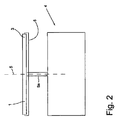
試験キャリア3は例えば図2に示される遠心デバイス4内で保持され、回転軸5を中心に回転される。遠心デバイス4は、回転可能に設置される回転シャフト5aの端部のところに設置されて試験キャリアを保持するホルダ6を装備する。回転シャフト5aは回転軸5と同心円状に配置される。ここで示される実施形態では、回転軸5は試験キャリア3の中心点を通って延在する。回転軸が素子1の中心点を通って延在しなかったりまたは素子1を通って延在しなかったりするような、マイクロ流体素子1の別の実施形態も可能であることは明白である。
The test carrier 3 is held, for example, in a centrifugal device 4 shown in FIG. The centrifuge device 4 is equipped with a holder 6 that is installed at the end of a rotating shaft 5a that is rotatably mounted to hold a test carrier. The rotating shaft 5 a is arranged concentrically with the
マイクロ流体素子1を回転式試験キャリア3として構成することは、それにより、移送システム2内の流体を制御するために外部の力を発生させることができる、考えられる一実施形態である。遠心力の代わりに、例えば、外部で生成される圧力による力が採用されてもよい。
Configuring the microfluidic device 1 as a rotating test carrier 3 is one possible embodiment whereby an external force can be generated to control the fluid in the
ここに示されるマイクロ流体素子1は血液試験に使用される。この点に関連して、複数のプロセスステップが連続して実施され、ここでは、このプロセスを進行させる際に、移送システム2の複数の部分または領域が複数回使用される。プロセスのステップの間で移送システム2のチャンネルを乾燥させることは不可能であるため、マイクロ流体素子1およびその中に含まれる移送システム2は、移送システム2の個別のチャンネルが複数回充填されるような場合でも、プロセス手順が安全に実施されるようにしなければならず、またここでは、特に、残留流体が残ることのために望ましくない空気気泡が発生しないようにしなければならない。
The microfluidic device 1 shown here is used for blood tests. In this regard, a plurality of process steps are carried out in succession, where a plurality of parts or regions of the
移送システム2は、チャンネル8およびチャンバ9をそれぞれが備える複数のチャンネル構造7を備える。これらのチャンネル構造7のうちの、複数回使用される1つが、廃棄物チャンバ12として形成されるチャンバ11と、試料流体を試験するための測定チャンバ10と廃棄物チャンバ12との間を延在するチャンネル13とを備える。廃棄物チャンバ12は、余分な流体またはそれ以降必要ない流体のための破棄物リザーバとして機能する。
The
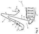
図3は、2つのチャンネル構造7a、7bを備える、図1の移送システム2の一区間を示し;図4aから4bは、チャンネル構造7aを備える一区間を示す。ここで説明される実施形態は回転式試験キャリアのみに限定されず、マイクロ流体チャンネルが複数回充填されるような移送システムを備える任意の試験キャリアで使用され得る。チャンネル構造7aは回収チャンバ15および測定チャンバ10を備え、さらには、回収チャンバ15と測定チャンバ10との間に配置される、サイフォン形状を有する流体チャンネル8を備える。このチャンネルはサイフォンバルブと称される。チャンネル構造7bは、測定チャンバ10と、サイフォン形状チャンネル13とを含み、さらには、一部分のみが示される廃棄物チャンバ12を含む。特定の一実施形態では、破棄物チャンバ12は、チャンバ内に流れる流体を吸い上げる繊維マット14を含む。試料流体を分析するのに必要となる反応は測定チャンバ10内で行われる。その反応には、例えば、固定された抗体を用いるマイクロアッセイが含まれてよい。簡略化のため、例えばチャンバ内にある、通気オリフィスは図示しない。
FIG. 3 shows a section of the
したがって、チャンネル構造7、7a、7bは、常に、第1のチャンバおよび第2のチャンバ、さらには、これらのチャンバを接続するチャンネル(毛細管チャンネル)を含む。好適には、このタイプのチャンネル構造のチャンネルは、形状がサイフォン状である、いわゆるサイフォンバルブである。チャンネル構造7aでは、第1のチャンバは回収チャンバ15であり、第2のチャンバは中間バルブチャンバ16である。チャンネル構造7bでは、第1のチャンバは測定チャンバ10であり、第2のチャンバは廃棄物チャンバ12である。
Accordingly, the
図4a、4bは中間バルブチャンバ16およびチャンネル8の詳細図を示し、図4bは等角図を示す。チャンネル8および中間バルブチャンバ16は、毛細管栓17を形成する幾何学的バルブを構成し、したがってここでは、毛細管作用によりチャンネル8内で移送される流体は中間バルブチャンバ16の上流で静止する。したがって、チャンネル8は流れ方向(矢印S)に作用する毛管力によって充填される。
4a and 4b show a detailed view of the
流体素子1が矢印Rの方向に回転されると、流体がこの場合では矢印rの方向である径方向外側に押される。回転振動数が貫流振動数に達すると、すなわち、マイクロ流体素子1が十分に速く回転されると、毛細管栓17がすぐに開き、流体がチャンネル8から流れ出て測定チャンバ10に入ることができる。中間バルブチャンバ16は入口オリフィス21を有するチャンバ壁20を装備し、流体はこの入口オリフィス21を介してチャンネル8から中間バルブチャンバ16内へと流れる。
When the fluid element 1 is rotated in the direction of the arrow R, the fluid is pushed outward in the radial direction, in this case the direction of the arrow r. When the rotational frequency reaches the once-through frequency, i.e. when the microfluidic device 1 is rotated sufficiently fast, the
チャンネル8は、チャンネル区間8と、流れ方向においてチャンネル区間8に隣接するバルブ区間19とを備える。本発明によると、バルブ区間19は、流れ方向において増大する流体移送断面を有する。入口オリフィス2のところにおける、バルブ区間19の流体移送断面は、チャンネル区間18からバルブ区間19までの移行部のところの流体移送断面より大きい。
The
チャンネル8の側壁22は好適にはチャンネル区間18内で互いに平行に延びる。バルブ区間19では、側壁(バルブ区間側壁26)は好適には平行ではなく、チャンネルの幅は拡張される。バルブ区間19の高さは一定であり、チャンネル8の高さは概して一定である。ここでの「高さ」という用語は、マイクロ流体素子1の表面の平面に対して垂直な寸法を意味する。
The
ここに示される実施形態では、入口オリフィス21のところにおけるバルブ区間19の幅(側壁22間の距離)は、チャンネル区間18からバルブ区間19までの移行部23のところのチャンネル8の幅より3倍大きい。
In the embodiment shown here, the width of the
本発明の文脈において、バルブ区間19の長さlが好適にはチャンネル区間18のところにおける側壁22の間の距離より少なくとも3倍大きく、好適には、チャンネル区間18からバルブ区間19までの移行部23のところの側壁22の間の距離より3倍大きいことが観察された。特に好適には、バルブ区間19の長さlは有利には移行部23のところにおける側壁22の間の距離の少なくとも5倍である。側壁22の間の距離の7倍の長さの場合、特に優れた特性を有するバルブ区間が提供されることが分かっている。
In the context of the present invention, the length l of the
図4aおよび4cによると、中間バルブチャンバ16はバルブ区間19に隣接する。ここを通過すると、中間バルブチャンバ16の関連断面積Qは入口オリフィス21のところにおけるバルブ区間19の端部の流体移送断面積qより大幅に大きいことから、このチャンネル構造の断面もやはり拡張される。
According to FIGS. 4 a and 4 c, the
図4cは、チャンネル8のバルブ区間19と、隣接する中間バルブチャンバ16との概略図を示す。流れ方方向sにおけるバルブ区間19の拡張、および、チャンバ壁20の入口オリフィス21のところの流体移送断面qを明瞭に見ることができる。バルブ区間19からチャンバ16までの第2の拡張を特徴付けるのに使用される関連チャンバ断面積Qをチャンバ壁から距離「a」のところに明瞭に見ることができる。入口オリフィスから0.2mmの距離が、関連チャンバ断面を設定するための適切な測定値であることが分かっている。好適には、関連チャンバ断面からチャンバ壁までの距離はチャンバ壁に対して垂直に測定される。チャンバの関連断面積は流体移送断面の表面に平行であるとする。
FIG. 4 c shows a schematic view of the
本実施例では、バルブ区間19の長さlは1.4mmであり、バルブ区間19とチャンネル区間18との間の移行部23のところの幅は0.2mmである。入口オリフィス21のところのバルブ区間19の幅は0.74mmである。バルブ区間の高さは0.15mmで一定する。バルブ区間の端部に一致する、入口オリフィス21から距離0.2mmのところの中間バルブチャンバ16は1.6mmの幅および0.5mmの高さを有する。これは0.8mm2の関連チャンバ断面積Qに相当する。入口オリフィス21のところの流体移送断面qと関連チャンバ断面積Qを比較すると、6.7の拡大率が得られる。これらの寸法により、チャンネル8を所望される通りに空にすることが確実に実施され、また、バルブ区間19の端部ところに所望される通りのバルブ機能が得られる。
In this embodiment, the length l of the
したがって、このバルブ機能は、チャンバ(ここでは中間バルブチャンバ16)の高さおよび/または幅が入口オリフィス21のところのバルブ区間19の高さおよび/または幅より大きい場合にも得られる。チャンバおよびバルブ区間に対して寸法を適切に選択することにより、入口オリフィス付近の深さおよび幅により形成されるチャンバ断面は、バルブ区間19の端部のところの流体移送断面より少なくとも1.5倍大きい。
This valve function is therefore also obtained when the height and / or width of the chamber (here intermediate valve chamber 16) is greater than the height and / or width of the
別法として、チャンネル構造7の機能を実施するために採用される寸法基準は、オリフィス21が中に配置されるチャンバ壁20のサイズであってもよい。チャンバ壁20の面積は、好適には、入口オリフィス21の面積の少なくとも1.5倍または少なくとも2倍でなければならない。この種の寸法設定を実現するために、チャンバ壁20の幅および/または高さは、相応して、入口オリフィス21の幅および/高さより大きくなければならない。その長さが移行部23のところにおける側壁22の間の距離の最大で10倍であるようなバルブ区間19を用いると、チャンネル8および回収チャンバ15は効率的に空にされ、チャンネル構造7a内に流体残留物が残ることはない。洗浄緩衝液溶液を使用する場合、バルブ区間19からの出口のところに石鹸膜が形成されることが高い信頼性で防止され、それによりチャンネル8が通気され得るようになる。
Alternatively, the dimensional criteria employed to perform the function of the channel structure 7 may be the size of the
したがって、好適には、中間バルブチャンバ16のチャンバ壁20上にバルブ区間19を非対称に配置することにより、バルブ区間19およびチャンネル区間18を含むチャンネル8を完全に空にすることがさらに改善される。側壁22のうちの1つは、チャンバ壁20に隣接するチャンバ側壁25により接近して配置される。チャンバ側壁25は、好適には、チャンバ壁に対して少なくとも80度から170度の角度で取り囲んでいるが、ここではこの角度は90度である。好適には、バルブ区間側壁26のうちの1つがチャンバ側壁25の近傍に配置され、ここでは、そのバルブ区間側壁26とチャンバ側壁25との間の距離27が最大でチャンネル区間18の幅と等しく、好適には、移行部23のところにおける側壁22の間の距離に等しい。本発明の文脈では、バルブ区間側壁26のうちの一方をチャンバ側壁25に可能な限り接近させて配置することが、残留物を排出することに関して有利であることが観察されている。一実施例として、距離27は最大で移行部23のところのチャンネル8の幅の半分であり、好適には最大でこの幅の3分の1である。
Accordingly, it is further improved to completely empty the
好適には、距離27は、バルブ区間側壁26とチャンバ側壁25との間においてチャンバ壁20の湾曲部29に対して測定される。この距離27は、好適には、移行部23のところのチャンネル8の幅の最大で3分の1であるべきである。チャンネルの幅が0.2mmである場合、距離27は最大で0.06mm程度になる。
Preferably, the distance 27 is measured relative to the
適切な回転方向(矢印R)を選択することにより、回転中に発生するコリオリの力と、回転の反対方向に作用する、加速中に発生するオイラーの力(Euler’s force)とにより、流体試料がバルブ区間19からチャンバ16まで移送されるときにその最も近い壁25に押圧され得るようになる。特に、この事実により、バルブ19から残留物が完全に排出されるようになり、また、チャンネル18が再び充填され得ることが保証される。
By selecting the appropriate direction of rotation (arrow R), the Coriolis force generated during rotation and the Euler's force generated during acceleration acting in the opposite direction of rotation When the sample is transferred from the
また、チャンネル13と、換気オリフィス(図示せず)を備える廃棄物チャンバ12とを備える図3のチャンネル構造7bも、サイフォン構造として構成され、流体を移送することを制御するためのサイフォンバルブとして機能する。図5および6は、チャンネル区間18およびバルブ区間19を備えるチャンネル13の一部分を詳細に示す。トランペット形状のバルブ区間19が流れ方向において拡張される。その流体移送断面は、移行部23のところより、チャンバ壁20内の入口オリフィス21のところの方が大きい。この実施形態では、バルブ区間19は廃棄物チャンバ12のチャンバ側壁25のところには配置されない。この場合、チャンネル13を確実に完全に空にするために、廃棄物チャンバ12がランプ30を備え、このランプ30は廃棄物チャンバ12の床部31のところに配置され、チャンバ壁20のところの入口オリフィス21から離れるように延在する。これに関連して、ランプ30の高さ36は、チャンバ壁20からの距離が増すにつれて減少する。ランプ30の頂面32はバルブ区間の床部33と厳密に同一面上にあり、したがって、図5に示されるように、さらには図6に示される図5内の線A−Aに沿った断面で使用されるように、連続的な移行部が形成される。ランプ30はまた、射出成形技術を使用してマイクロ流体素子1の基体34内、または試験キャリア3内にも作られる。したがって、ランプ30を作ることによってコストが増大することはない。
The
同様に廃棄物チャンバ12として形成されるチャンバ11の場合、入口オリフィス21から0.2mmの距離のところの関連チャンバ断面Qが入口オリフィス21のところの流体移送断面qより1.5倍大きいことが有利であることが分かっている。本実施形態に対する試験により、チャンバ12内でランプ30を備える構成であるが、ランプ30がバルブ区間19の床部への連続的な移行部を構成する場合でも、この基準が満たされることが分かった。入口オリフィス21から0.4mmの距離のところでは、入口オリフィスのところの流体移送断面qに対する関連チャンバ断面Qの比が大幅に大きくなり、この場合では36倍大きい。これは、チャンネル8を残留物がなくなるよう空にするための所望される機能および入口オリフィス21のところのバルブ機能が、高い信頼性で実現されることを意味する。
Similarly, in the case of a
ランプ30を介したバルブ区間19から廃棄物チャンバ12までの床部上の連続的な移行部により、図4a、4bに関連させて説明した前の実施形態における、バルブ区間19を一方のチャンバ側壁25に接近させて配置する場合と同様に、バルブ区間19およびチャンネル8を空にすることがさらに改善される。
Due to the continuous transition on the floor from the
好適には、ランプ30は、その頂部側32が平坦となるように、構成される。別法として、頂部側32は湾曲していてもよい。バルブ区間19の床部33とランプ30の頂部側32とによって形成される「接線方向」移行部(湾曲部30)は、好適には、Z方向(図6を参照)に好適には1.25mmから2.25mmの範囲の湾曲半径(rounding radius)を有するように丸められる。本実施例では、湾曲部35の半径は1.75mmである。
Preferably, the
好適な一実施形態では、バルブ区間19は、バルブ区間側壁26が少なくとも部分的に直線状に延びるように、構成される。入口オリフィス21に向かうバルブ区間19の端部では、実用試験により、チャンバ壁20への移行部内の湾曲部37が有利であることが分かった。X−Y方向の湾曲部37は、好適には、0.5mmから1mmの範囲の湾曲半径を有し、示される実施形態ではこれは0.65mmである。
In a preferred embodiment, the
有利には、ランプ30の幅38は入口オリフィス21の幅bより大きい。好適には、このランプは、入口オリフィス21より少なくとも10%から50%広く、特に好適にはその幅は2倍である。本発明の文脈では、入口オリフィス21の幅bの3倍の幅38を備えるランプ30がやはり有利であることが分かっている。ランプ30の幅は、入口オリフィス21の幅b(湾曲部37を有さない)より最大で5倍大きくあるべきである。ランプ30は横方向において入口オリフィス21と重なることから、ランプを横方向において丸めることは必要ない。ランプ30の側部により廃棄物チャンバ12のチャンバ床部31への急激な移行部を形成することが有利であることが分かっている。これにより、廃棄物チャンバから出る流体がバルブ区間19へと環流することが防止される。
Advantageously, the
また、廃棄物チャンバ12内でランプ30を使用することにより、バルブ区間19内に形態された石鹸膜が「チャンバ内に引き寄せられる」ようになり、それにより石鹸膜が破壊される。チャンネル13からの流体残留物は凝集力によりランプ30を介して離れる方向に誘導される。
Also, the use of the
図7は、本発明の代替のチャンネル構造7を備えるマイクロ流体素子1の移送システム2の断面図を示す。この移送システム2は、チャンネル13と、任意選択の繊維マット14を備える廃棄物チャンバ12とを備える。廃棄物チャンバ12は、その端部のところに、通気オリフィス51を備える通気チャンネル50を有し、空気はこの通気オリフィス51を介して廃棄物チャンバ12およびチャンネル構造7から逃がされ得る。チャンネル13は、チャンネル区間18と、隣接するバルブ区間19とを備え、廃棄物チャンバ12を備える毛細管栓を形成する。流体は、毛細管栓が貫流されているときのみ廃棄物チャンバ12内に流れ込むことができる。
FIG. 7 shows a cross-sectional view of a
2つのバルブ区間側壁26の間において、バルブ区間19は好適にはリブ40を備え、それにより、隣接して配置される2つのバルブ区間サブチャンネル41、42が形成される。バルブ区間19のこのサブ区間42内でも同様に、図7、8に見られるように、流体移送断面が流れ方向Sにおいて拡張される。
Between the two valve
好適には、第1のバルブ区間サブチャンネル41が主サブチャンネル43を形成し、第2のバルブ区間サブチャンネル42がバイパスサブチャンネル44を形成する。この場合のこれらの2つのサブチャンネル41、42は65度の角度を有する。 Preferably, the first valve section subchannel 41 forms the main subchannel 43 and the second valve section subchannel 42 forms the bypass subchannel 44. These two subchannels 41, 42 in this case have an angle of 65 degrees.
図8、9に見られるように、主サブチャンネル43はチャンネル区間18に位置合わせされる。図9はバルブ区間の等角図を示す。主サブチャンネル43の幅および高さはチャンネル区間18の幅および高さに一致する。主サブチャンネル43の側壁は好適には互いに平行である。主サブチャンネル43の高さは好適には0.14mmから0.2mmの範囲、特に好適には0.15mmから0.18mmの範囲である。ここに示される実施例では、主サブチャンネル43の高さは0.15mmであり、幅は0.2mmである。
As can be seen in FIGS. 8 and 9, the main sub-channel 43 is aligned with the
バイパスサブチャンネル44は好適には主サブチャンネル43より幅が広い。好適には、バイパスサブチャンネル44は、分岐部位45から廃棄物チャンバ12のチャンバ壁20内のバイパス入口オリフィス46に向かって、広くなる。したがって、バイパスサブチャンネル44の流体移送断面は流れ方向において拡張される。本実施例では、分岐部位45のところのバイパスサブチャンネル44の幅は0.38mmであり、バイパス入口オリフィス46のところの幅(バルブ区間側壁26に平行)は0.6mmである。バイパス入口オリフィス46のところのバイパスサブチャンネル44の高さ(Z方向)は0.24mmから0.3mmの範囲内にあるべきであり、好適には0.25mmから0.28mmの範囲内にあるべきである。示される実施形態では、高さは0.25mmである。示される実施例の廃棄物チャンバ12の高さは1.4mmである。
The bypass subchannel 44 is preferably wider than the main subchannel 43. Preferably, the bypass subchannel 44 widens from the
チャンバ壁20のところのバイパスサブチャンネル44の高さは好適にはチャンバ壁20のところの主サブチャンネル43のところの高さより大きい(図9)。好適には、ここで示されるように、分岐部位45のところの2つのサブチャンネル41、42の高さは等しい。
The height of the bypass subchannel 44 at the
バルブ区間19の一実施形態(図7から9)では、主サブチャンネル43は、90度以外の角度で、廃棄物チャンバ12のチャンバ壁20に接触する。好適には、主サブチャンネル43はチャンバ壁43に対して直角となるように配置される。
In one embodiment of the valve section 19 (FIGS. 7-9), the main subchannel 43 contacts the
この実施形態でも同様に、チャンバ壁20付近の関連チャンバ断面Qは入口オリフィス21および46のところの流体移送断面qより大幅に大きい。また、毛細管栓を備えるバルブ機構が得られることおよびこのチャンバ内のチャンネル8が空になることも保証される。好適には、ここでもやはり、関連チャンバ断面Qはチャンバ壁20から0.2mmの距離のところで決定される。この距離はチャンバ壁20に対して垂直である。
In this embodiment as well, the associated chamber cross section Q near the
図7、8は、リブ40を備えるバルブ区間19がバイパスサブチャンネル44を形成するのを示す。バルブ区間19は好適には以下のような形でチャンバ12のところに配置される:バイパスサブチャンネル44が、主サブチャンネル43と比較して、チャンバ側壁25により接近して配置されること。チャンバ側壁25に対してバイパスサブチャンネル44がこのように空間的に近接することは、トランペット形状のバルブ区間と同様の効果が得られることを意味する。ここでもやはり、排出するときに流体柱が分割されることが防止され、高い信頼性で残留物が排出される。
7 and 8 show that the
チャンネル構造7a(図3)では、バルブ区間19は流れ方向においてトランペット状に拡張される。バルブ区間19の回転方向Rに対向するように方向付けられる側壁26(右側の側壁)がチャンバ側壁25に接近している。マイクロ流体素子1は時計回り方向(矢印R)に回転されることから、マイクロ流体素子1が加速されると、チャンネル8内に含まれる流体がチャンネル8の右側の側壁22に対して押圧される。この側壁22、26はチャンバ側壁25に接近しており、それにより、チャンネル8を空にすることが、回転中に発生するコリオリの力および加速中に発生するオイラーの力によって最適化される。チャンネル8を通気することおよびしたがってチャンネル8を再充填することも効果的に保証される。
In the
一方で、図7、8、9による、バイパスを備えるバルブ区間19の実施形態では、バイパスサブチャンネル44がチャンバ側壁25に接近している。この場合、反時計回りに回転する。この場合、回転中に発生するコリオリの力および加速中に発生するオイラーの力により、流体は、バルブ区間のサブ毛細管42に隣接するチャンバ11の左側の壁25に対して押圧され、バイパスサブチャンネル44を空にするのを補助する。洗浄緩衝液容器を使用する場合には、石鹸膜が形成されることが防止される。バイパスサブチャンネル44を通してチャンネル13を効率的に通気させることができることから、バルブ区間19の主サブチャンネル43の比較的狭いところでは石鹸膜が形成されることが深刻かつ有害であったりすることはない。先ず、予め設定された貫流振動数に達し(回転振動数が貫流振動数を超える)、その後、バイパスサブチャンネル44を介して、チャンネル13が空にされてさらにはバルブ区間19が貫流されるが、ここでのバイパスサブチャンネル44は、その流体移送断面が拡張されているが、依然として毛細管作用によって充填されることが可能であるように、構成される。バイパスサブチャンネル44は以下のように設計される:排出する作業が終わりに近づいても流体が分割されることがなく、したがって確実に排出されることさらにはそれにより通気されることが保証される。このように、サイフォン状構成のサイフォンバルブチャンネル13は高い信頼性で複数回使用され得る。
On the other hand, in the embodiment of the
主サブチャンネル43は、チャンバ側壁から離れるように配置されることから、チャンバから出る流体が環流するのを防止する働きをする。破棄物チャンバ12から出てチャンバ壁20に沿ってバルブ区間19の方向に戻るように流れてチャンバ壁20を湿らせている流体が、毛細管作用を受けて狭いサブチャンネル43内に送られる。これは、主サブチャンネル43の断面が小さく、したがってバイパスサブチャンネル44より毛細管効果が高いからである。このように、凝集力により、逆流する流体は狭い主サブチャンネル43内に誘導されることから、バイパスサブチャンネル44に到達することはない。したがって、バイパスサブチャンネル44が閉鎖されることはなく、移行部が、チャンバから出る流体が逆流することから保護される。このことは、特に、廃棄物チャンバが徐々に充填されていく場合に、重要となる可能性がある。
Since the main subchannel 43 is disposed away from the chamber side wall, it functions to prevent the fluid exiting the chamber from circulating. Fluid that exits the
マイクロ流体素子が静止している場合、毛細管作用により流体が測定チャンバ10から出て、チャンネル13内へと流れ込む。この点に関連して、先ず、狭い主サブチャンネル43が比較的迅速に充填される。次いで、バイパスサブチャンネル44のみが充填され、したがってバイパスサブチャンネル44は主サブチャンネル43より緩やかに充填される。特にバイパスサブチャンネル44を拡張させさらには2つのサブチャンネル41、42の間の角度を調整することにより、2つのサブチャンネル41、42を適切に構成することで、生じる毛管力との関係により充填を調整することが可能となる。
When the microfluidic device is stationary, fluid exits the
マイクロ流体が回転し始めるとすぐに、バイパスサブチャンネル44が最初に貫流される。これは、振動数が比較的低くても起こる。したがって、生化学分析プロセス(生化学分析アッセイ)では、例えばタンパク質などを損傷させないように、チャンバを慎重に空にすることが可能である。 As soon as the microfluidic begins to rotate, the bypass subchannel 44 is initially flowed through. This occurs even at relatively low frequencies. Thus, in a biochemical analysis process (biochemical analysis assay), the chamber can be carefully emptied so as not to damage, for example, proteins.
本発明によるバルブ区間19では、チャンネルを閉鎖することなく同一の毛細管または同一のチャンネル8、13を使用して複数のプロセスステップ(アッセイステップ)を高い堅牢性で実施することができることを示してきた。また、複数のプロセスステップにわたって、毛細管(チャンネル8、13)を通気させることが保証され、したがって、種々の流体を複数回導入すること保証される。したがって、石鹸膜を形成させることなく、また、残留溶液(残留流体)を混合させることまたは残留溶液(残留流体)によりチャンネルを再充填させることなく、高い洗浄剤濃度を有する容器も使用され得る。
The
Claims (11)
前記チャンネル構造(7)が、2つの側壁(22)を備えるチャンネル(8、13)、および前記チャンネル(8、13)に隣接するチャンバ(9、11)を備え、
前記チャンネル(8、13)が、チャンネル区間(18)、および前記チャンネル区間(18)に隣接するバルブ区間(19)を備え、前記チャンネル(8、13)の少なくとも一部は、毛細管作用を発生させるように構成され、
前記2つの側壁(22)が、前記チャンネル区間(18)内で互いに平行に延び、
前記チャンバ(9、11)が、入口オリフィス(21)を備えるチャンバ壁(20)を有し、
前記チャンバ壁(20)内の前記入口オリフィス(21)が前記バルブ区間(19)に隣接し、それにより、流体が前記チャンネル区間(18)から出て前記バルブ区間(19)を通って前記チャンバ(9、11)内まで流れることができ、
前記バルブ区間(19)が流れ方向において拡大する流体移送断面を有し、前記バルブ区間(19)の前記流体移送断面が、前にある前記チャンネル区間(18)内の流体移送断面より大きく、
前記バルブ区間(19)および前記チャンバ(9、11)が、幾何学的バルブを構成する毛細管栓(17)を形成し、それにより、前記チャンネル(8、13)を通って流れる流体が、前記チャンバ(9、11)の前記入口オリフィス(21)のところにある前記バルブ区間(19)の端部のところで停止され、
リブ(40)が、前記バルブ区間の2つの側壁(26)の間の前記バルブ区間(19)内に配置され、共に前記チャンバ(9、11)の前記チャンバ壁(20)のところで終端する2つの隣接するバルブ区間サブチャンネル(41、42)が形成され、前記チャンバ壁(20)のところにおける第2のバルブ区間サブチャンネル(42)から第1のバルブ区間サブチャンネル(41)までの距離が、より狭いバルブ区間サブチャンネル(41、42)より少なくとも2倍の幅である、
マイクロ流体素子。 A fluid sample comprising a substrate (34) and a microfluidic transfer system (2) having a channel structure (7), wherein the microfluidic transfer system (2) is surrounded by the substrate (34) and a coating layer. A microfluidic device for analysis comprising:
The channel structure (7) comprises a channel (8, 13) comprising two side walls (22) and a chamber (9, 11) adjacent to the channel (8, 13);
The channel (8, 13) includes a channel section (18) and a valve section (19) adjacent to the channel section (18), and at least a part of the channel (8, 13) generates capillary action. Configured to let
The two side walls (22) extend parallel to each other in the channel section (18);
The chamber (9, 11) has a chamber wall (20) with an inlet orifice (21);
The inlet orifice (21) in the chamber wall (20) is adjacent to the valve section (19) so that fluid exits the channel section ( 18 ) and through the valve section (19). (9, 11)
The valve section (19) has a fluid transfer section that expands in the flow direction, the fluid transfer section of the valve section (19) being larger than the fluid transfer section in the preceding channel section (18);
The valve section (19) and the chamber (9, 11) form a capillary plug (17) that constitutes a geometric valve, so that the fluid flowing through the channels (8, 13) Stopped at the end of the valve section (19) at the inlet orifice (21) of the chamber (9, 11) ,
A rib (40) is disposed in the valve section (19) between the two side walls (26) of the valve section and both terminate at the chamber wall (20) of the chamber (9, 11). Two adjacent valve section subchannels (41, 42) are formed, and the distance from the second valve section subchannel (42) to the first valve section subchannel (41) at the chamber wall (20) is , At least twice as wide as the narrower valve section subchannels (41, 42),
Microfluidic device.
前記バルブ区間(19)の前記バイパスサブチャンネル(44)が、前記バルブ区間(19)の前記主サブチャンネル(43)よりも、前記チャンバ側壁(25)に接近して配置されることを特徴とする、請求項7から9までのいずれか1項に記載のマイクロ流体素子。 The chamber (9, 11) comprises a chamber side wall (25) adjacent to the chamber wall (20);
The bypass subchannel (44) of the valve section (19) is disposed closer to the chamber side wall (25) than the main subchannel (43) of the valve section (19). The microfluidic device according to any one of claims 7 to 9 .
Applications Claiming Priority (3)
| Application Number | Priority Date | Filing Date | Title |
|---|---|---|---|
| EP10189383A EP2455162A1 (en) | 2010-10-29 | 2010-10-29 | Microfluidic element for analysing a fluid sample |
| EP10189383.2 | 2010-10-29 | ||
| PCT/EP2011/068638 WO2012055861A1 (en) | 2010-10-29 | 2011-10-25 | Microfluidic element for analysis of a sample liquid |
Publications (3)
| Publication Number | Publication Date |
|---|---|
| JP2013541014A JP2013541014A (en) | 2013-11-07 |
| JP2013541014A5 JP2013541014A5 (en) | 2014-09-25 |
| JP5964844B2 true JP5964844B2 (en) | 2016-08-03 |
Family
ID=43618942
Family Applications (1)
| Application Number | Title | Priority Date | Filing Date |
|---|---|---|---|
| JP2013535401A Expired - Fee Related JP5964844B2 (en) | 2010-10-29 | 2011-10-25 | Microfluidic device for analyzing sample liquids |
Country Status (6)
| Country | Link |
|---|---|
| US (1) | US9221051B2 (en) |
| EP (2) | EP2455162A1 (en) |
| JP (1) | JP5964844B2 (en) |
| KR (1) | KR101506936B1 (en) |
| CN (1) | CN103167910B (en) |
| WO (1) | WO2012055861A1 (en) |
Families Citing this family (13)
| Publication number | Priority date | Publication date | Assignee | Title |
|---|---|---|---|---|
| WO2014059134A1 (en) * | 2012-10-11 | 2014-04-17 | Siemens Healthcare Diagnostics Inc. | Automation maintenance carrier |
| CN103464230B (en) * | 2013-09-25 | 2015-02-18 | 中国科学院长春光学精密机械与物理研究所 | Centrifugal whole blood analysis micro-fluidic chip, preparation method as well as application method thereof |
| EP2952257A1 (en) | 2014-06-06 | 2015-12-09 | Roche Diagnostics GmbH | Rotatable cartridge for processing and analyzing a biological sample |
| EP2952258A1 (en) * | 2014-06-06 | 2015-12-09 | Roche Diagnostics GmbH | Rotatable cartridge for analyzing a biological sample |
| WO2015185763A1 (en) | 2014-06-06 | 2015-12-10 | Roche Diagnostics Gmbh | Rotatable cartridge with a metering chamber for analyzing a biological sample |
| EP2957890A1 (en) * | 2014-06-16 | 2015-12-23 | Roche Diagnostics GmbH | Cartridge with a rotatable lid |
| DE102014019526B4 (en) * | 2014-12-23 | 2016-10-27 | Testo Ag | Examination procedure, disk-shaped sample carrier and use of a sample carrier |
| CN107305210B (en) * | 2016-04-20 | 2019-09-17 | 光宝电子(广州)有限公司 | Biological detection cassette and its current method for detecting fluid |
| WO2017191080A1 (en) * | 2016-05-02 | 2017-11-09 | Danmarks Tekniske Universitet | A method for preparing a substrate by applying a sample to be analysed |
| DE102016207845B4 (en) * | 2016-05-06 | 2018-04-12 | Hahn-Schickard-Gesellschaft für angewandte Forschung e.V. | Fluid handling device and method of fluid handling |
| EP3324189B1 (en) * | 2016-11-16 | 2021-01-06 | Roche Diagnostics GmbH | Rotatable cartridge with multiple metering chambers |
| US11213824B2 (en) | 2017-03-29 | 2022-01-04 | The Research Foundation For The State University Of New York | Microfluidic device and methods |
| CN113617401B (en) * | 2020-05-08 | 2023-06-06 | 浙江普施康生物科技有限公司 | Centrifugal detection flow channel, detection device and detection method |
Family Cites Families (39)
| Publication number | Priority date | Publication date | Assignee | Title |
|---|---|---|---|---|
| FR2400700A1 (en) | 1977-08-18 | 1979-03-16 | Guigan Jean | CONDITIONING DEVICE FOR A LIQUID SAMPLE FOR ANALYSIS |
| US4426451A (en) * | 1981-01-28 | 1984-01-17 | Eastman Kodak Company | Multi-zoned reaction vessel having pressure-actuatable control means between zones |
| US5160702A (en) | 1989-01-17 | 1992-11-03 | Molecular Devices Corporation | Analyzer with improved rotor structure |
| US5061381A (en) | 1990-06-04 | 1991-10-29 | Abaxis, Inc. | Apparatus and method for separating cells from biological fluids |
| US5304348A (en) | 1992-02-11 | 1994-04-19 | Abaxis, Inc. | Reagent container for analytical rotor |
| WO1993019827A1 (en) | 1992-04-02 | 1993-10-14 | Abaxis, Inc. | Analytical rotor with dye mixing chamber |
| US5591643A (en) | 1993-09-01 | 1997-01-07 | Abaxis, Inc. | Simplified inlet channels |
| EP0764266A4 (en) | 1994-06-06 | 1998-08-05 | Abay Sa | Modified siphons for improved metering precision |
| US20010055812A1 (en) * | 1995-12-05 | 2001-12-27 | Alec Mian | Devices and method for using centripetal acceleration to drive fluid movement in a microfluidics system with on-board informatics |
| US6143248A (en) * | 1996-08-12 | 2000-11-07 | Gamera Bioscience Corp. | Capillary microvalve |
| BR9909249B1 (en) * | 1998-03-11 | 2009-12-01 | sample holder. | |
| US6162400A (en) | 1998-08-12 | 2000-12-19 | Agilent Technologies, Inc. | Apparatus for controlling reactions |
| US6601613B2 (en) * | 1998-10-13 | 2003-08-05 | Biomicro Systems, Inc. | Fluid circuit components based upon passive fluid dynamics |
| KR20010089295A (en) * | 1998-10-13 | 2001-09-29 | 마이클 알. 맥닐리 | Fluid circuit components based upon passive fluid dynamics |
| SE0001779D0 (en) | 2000-05-12 | 2000-05-12 | Gyros Ab | Microanalysis device |
| EP1201304B1 (en) * | 2000-10-25 | 2006-08-16 | Boehringer Ingelheim microParts GmbH | Microstructured platform for examining a liquid |
| AU2002249481A1 (en) * | 2000-10-25 | 2002-08-12 | Exiqon A/S | Open substrate platforms suitable for analysis of biomolecules |
| US6919058B2 (en) | 2001-08-28 | 2005-07-19 | Gyros Ab | Retaining microfluidic microcavity and other microfluidic structures |
| WO2003024598A1 (en) * | 2001-09-17 | 2003-03-27 | Gyros Ab | Functional unit enabling controlled flow in a microfluidic device |
| FR2841158B1 (en) * | 2002-06-24 | 2007-02-23 | Bio Merieux | THERMO-PNEUMATICALLY FLEXIBLE FLUID DEVICE ISOLATION AND POSSIBLY AGITATION OF THE CONTENT OF AN OPERATIVE CAVITY |
| KR100480338B1 (en) * | 2002-08-08 | 2005-03-30 | 한국전자통신연구원 | Microfluidic devices for the controlled movements of solution |
| US7125711B2 (en) | 2002-12-19 | 2006-10-24 | Bayer Healthcare Llc | Method and apparatus for splitting of specimens into multiple channels of a microfluidic device |
| DE10302720A1 (en) * | 2003-01-23 | 2004-08-05 | Steag Microparts Gmbh | Microfluidic switch for stopping the flow of fluid during a time interval |
| EP1525916A1 (en) * | 2003-10-23 | 2005-04-27 | F. Hoffmann-La Roche Ag | Flow triggering device |
| DE10360220A1 (en) * | 2003-12-20 | 2005-07-21 | Steag Microparts Gmbh | Fine structure arrangement in fluid ejection system, has predetermined region in transitional zone between inlet and discharge ports, at which capillary force is maximum |
| KR100540143B1 (en) * | 2003-12-22 | 2006-01-10 | 한국전자통신연구원 | Microfluidic control device and method for controlling microfluidic |
| DE102004027422A1 (en) | 2004-06-04 | 2005-12-29 | Boehringer Ingelheim Microparts Gmbh | Device for receiving blood and separating blood components |
| US20060002817A1 (en) * | 2004-06-30 | 2006-01-05 | Sebastian Bohm | Flow modulation devices |
| WO2006022495A1 (en) * | 2004-08-21 | 2006-03-02 | Lg Chem, Ltd. | A capillary flow control module and lab-on-a-chip equipped with the same |
| DE102004063438A1 (en) * | 2004-12-23 | 2006-07-06 | Oktavia Backes | Novel microfluidic sample carriers |
| CN101262948B (en) * | 2005-06-06 | 2011-07-06 | 决策生物标志股份有限公司 | Assays based on liquid flow over arrays |
| DE102005048260A1 (en) | 2005-10-07 | 2007-04-12 | Albert-Ludwigs-Universität Freiburg | A method and apparatus for handling a liquid sample using rotation with a time-varying rotary vector |
| JPWO2007116909A1 (en) | 2006-04-04 | 2009-08-20 | パナソニック株式会社 | Sample solution analysis panel |
| EP1977829A1 (en) | 2007-03-29 | 2008-10-08 | Roche Diagnostics GmbH | Device for performing multiple analyses in parallel |
| EP1977830A1 (en) * | 2007-03-30 | 2008-10-08 | Roche Diagnostics GmbH | Micro-fluidic temperature driven valve |
| JP2008256493A (en) * | 2007-04-04 | 2008-10-23 | Matsushita Electric Ind Co Ltd | Chemical examination plate |
| EP2072131B1 (en) * | 2007-12-13 | 2015-04-22 | Roche Diagnostics GmbH | Microfluid element for mixing a fluid into a reagent |
| WO2009099512A2 (en) * | 2008-02-04 | 2009-08-13 | Micropoint Biosciences, Inc. | Centrifugal fluid analyzer rotor |
| JP4784652B2 (en) * | 2008-02-26 | 2011-10-05 | パナソニック電工株式会社 | Power supply device |
-
2010
- 2010-10-29 EP EP10189383A patent/EP2455162A1/en not_active Withdrawn
-
2011
- 2011-10-25 EP EP11773475.6A patent/EP2632591B1/en active Active
- 2011-10-25 KR KR1020137013691A patent/KR101506936B1/en not_active IP Right Cessation
- 2011-10-25 CN CN201180052210.XA patent/CN103167910B/en not_active Expired - Fee Related
- 2011-10-25 WO PCT/EP2011/068638 patent/WO2012055861A1/en active Application Filing
- 2011-10-25 JP JP2013535401A patent/JP5964844B2/en not_active Expired - Fee Related
-
2013
- 2013-04-29 US US13/872,686 patent/US9221051B2/en active Active
Also Published As
| Publication number | Publication date |
|---|---|
| CN103167910B (en) | 2016-12-07 |
| KR101506936B1 (en) | 2015-03-31 |
| EP2455162A1 (en) | 2012-05-23 |
| JP2013541014A (en) | 2013-11-07 |
| EP2632591A1 (en) | 2013-09-04 |
| CN103167910A (en) | 2013-06-19 |
| US9221051B2 (en) | 2015-12-29 |
| WO2012055861A1 (en) | 2012-05-03 |
| US20130243664A1 (en) | 2013-09-19 |
| KR20140009217A (en) | 2014-01-22 |
| EP2632591B1 (en) | 2018-12-26 |
Similar Documents
| Publication | Publication Date | Title |
|---|---|---|
| JP5964844B2 (en) | Microfluidic device for analyzing sample liquids | |
| JP5908917B2 (en) | A microfluidic test carrier for allocating a certain volume of liquid to partial volumes | |
| JP6494658B2 (en) | Rotatable cartridge for analyzing biological samples | |
| JP6527531B2 (en) | Rotatable cartridge comprising a metering chamber for analyzing a biological sample | |
| US9421540B2 (en) | Microfluidic device with auxiliary and bypass channels | |
| JP5050178B2 (en) | Microfluidic chip for fluid sample analysis | |
| JP2007232674A (en) | Centrifugal separation device and centrifugal separation method | |
| JP6604966B2 (en) | Rotatable cartridge for processing and analyzing biological samples | |
| JP2004500578A (en) | Method for reducing fluid carryover in microfluidic devices | |
| JP2005230816A (en) | Platform microstructured to process liquid and using method of the same | |
| JP5182366B2 (en) | Microchip, microchip liquid feeding system, and microchip liquid feeding method | |
| JP5376427B2 (en) | Analytical device | |
| JP4181497B2 (en) | Microfluidic microcavity and other microfluidic structures for holding | |
| CN108855258B (en) | Microfluidic inspection device and microfluidic control method thereof | |
| JP4869205B2 (en) | Microfluidic device and microfluidic device apparatus | |
| JP4339200B2 (en) | Sample supply element for immunochromatography equipment | |
| CN112996599A (en) | Diagnostic device | |
| JP2007212285A (en) | Fluid handling device | |
| JP2007521496A (en) | Large-scale surface improvement of microfluidic devices | |
| CN114768899A (en) | Micro-fluidic chip applying phase change valve and in-vitro diagnostic device | |
| JP2014134476A (en) | Micro flow passage device |
Legal Events
| Date | Code | Title | Description |
|---|---|---|---|
| A521 | Written amendment |
Free format text: JAPANESE INTERMEDIATE CODE: A523 Effective date: 20140807 |
|
| A621 | Written request for application examination |
Free format text: JAPANESE INTERMEDIATE CODE: A621 Effective date: 20140807 |
|
| A977 | Report on retrieval |
Free format text: JAPANESE INTERMEDIATE CODE: A971007 Effective date: 20150527 |
|
| A131 | Notification of reasons for refusal |
Free format text: JAPANESE INTERMEDIATE CODE: A131 Effective date: 20150616 |
|
| A521 | Written amendment |
Free format text: JAPANESE INTERMEDIATE CODE: A523 Effective date: 20150909 |
|
| A131 | Notification of reasons for refusal |
Free format text: JAPANESE INTERMEDIATE CODE: A131 Effective date: 20160226 |
|
| A521 | Written amendment |
Free format text: JAPANESE INTERMEDIATE CODE: A523 Effective date: 20160511 |
|
| TRDD | Decision of grant or rejection written | ||
| A01 | Written decision to grant a patent or to grant a registration (utility model) |
Free format text: JAPANESE INTERMEDIATE CODE: A01 Effective date: 20160601 |
|
| A61 | First payment of annual fees (during grant procedure) |
Free format text: JAPANESE INTERMEDIATE CODE: A61 Effective date: 20160630 |
|
| R150 | Certificate of patent or registration of utility model |
Ref document number: 5964844 Country of ref document: JP Free format text: JAPANESE INTERMEDIATE CODE: R150 |
|
| LAPS | Cancellation because of no payment of annual fees |