JP5964255B2 - Container with pump - Google Patents
Container with pump Download PDFInfo
- Publication number
- JP5964255B2 JP5964255B2 JP2013015773A JP2013015773A JP5964255B2 JP 5964255 B2 JP5964255 B2 JP 5964255B2 JP 2013015773 A JP2013015773 A JP 2013015773A JP 2013015773 A JP2013015773 A JP 2013015773A JP 5964255 B2 JP5964255 B2 JP 5964255B2
- Authority
- JP
- Japan
- Prior art keywords
- cover
- container
- peripheral wall
- pump
- wall
- Prior art date
- Legal status (The legal status is an assumption and is not a legal conclusion. Google has not performed a legal analysis and makes no representation as to the accuracy of the status listed.)
- Active
Links
Images


Landscapes
- Containers And Packaging Bodies Having A Special Means To Remove Contents (AREA)
- Closures For Containers (AREA)
Description
本発明は、容器の口部にポンプを備えるポンプ付き容器に関するものであり、特に、ポンプの誤操作を簡単な構成で防止する容器に関する。 The present invention relates to a container with a pump provided with a pump at the mouth of the container, and more particularly to a container that prevents erroneous operation of the pump with a simple configuration.
従来、ポンプの誤作動を防止するために、押下ヘッド(吐出部)を覆うオーバーキャップ(カバー)を設け、このオーバーキャップを下方にスライド移動させることで押下ヘッドを突出させ、該押下ヘッドを操作可能とする誤操作防止機能を備えたポンプ付き容器が知られている(例えば特許文献1)。 Conventionally, in order to prevent malfunction of the pump, an overcap (cover) that covers the pressing head (discharge section) has been provided, and the pressing head protrudes by sliding the overcap downward, and the pressing head is operated. A container with a pump having a function to prevent erroneous operation is known (for example, Patent Document 1).
ところで、従来の容器の使用に当たっては、オーバーキャップをスライド移動させた後に押下ヘッドを押圧するという、同軸方向の操作を繰り返し行う必要があり、その操作性に改善の余地があった。また、押下ヘッドをオーバーキャップで覆った保管状態においても、押下ヘッドの天面壁がオーバーキャップの上面開口から露出しているため、この状態で誤作動が生じる可能性が懸念された。 By the way, when the conventional container is used, it is necessary to repeatedly perform the operation in the coaxial direction of pressing the pressing head after sliding the overcap, and there is room for improvement in operability. Further, even in the storage state where the pressing head is covered with the overcap, the top wall of the pressing head is exposed from the upper surface opening of the overcap, and there is a concern that malfunction may occur in this state.
本発明は、このような問題を解決することを課題とするものであり、その目的は、簡単な構成で誤操作を防止するとともに、吐出操作の操作性を高めた新規のポンプ付き容器を提案するところにある。 An object of the present invention is to solve such a problem, and an object of the present invention is to propose a new pump-equipped container that prevents erroneous operation with a simple configuration and improves operability of discharge operation. By the way.
本発明は、容器の内側に繋がる開口を有し該容器の口部に固定保持されるベースキャップと、該開口を通して吊り下げ保持されステムの押し込みと復帰動作の繰り返しにより内容物を吸引、加圧、圧送するポンプと、該ステムに連結する吐出部を設けるとともに少なくとも該ベースキャップを取り囲むカバー周壁を該吐出部の周壁と一体連結させたカバーと、該カバー上に設けられた蓋体とを備え、
前記吐出部は、該周壁の上方を閉鎖する天面壁を有し、該天面壁及び周壁の少なくとも一方に内容物の注出口を備えており、
前記カバーは、前記天面壁及び周壁の一部を切り取った切り欠き部を有し、前記蓋体は、該切り欠き部に適合する延長部を備え、
該延長部は、該切り欠き部の端面に設けた軸部又は軸受け部に適合して該蓋体を揺動可能に保持する軸受け部又は軸部を有するとともに、該蓋体の閉鎖姿勢時に前記ベースキャップの一部に対して当接するか僅かに隙間をあけた所に位置してステムに繋がる前記カバーの押し込みを阻止する端部を備える、ポンプ付き容器である。
The present invention has a base cap that has an opening connected to the inside of the container and is fixedly held at the mouth of the container, and is held by being suspended through the opening, and the contents are sucked and pressurized by repeating the pushing and returning operation of the stem. A pump for pumping, a discharge portion connected to the stem, and a cover in which at least a cover peripheral wall surrounding the base cap is integrally connected to the peripheral wall of the discharge portion, and a lid provided on the cover ,
The discharge part has a top wall that closes above the peripheral wall, and has a spout for contents on at least one of the top wall and the peripheral wall,
The cover has a cutout part obtained by cutting out a part of the top wall and the peripheral wall, and the lid body includes an extension part adapted to the cutout part,
The extension portion has a bearing portion or a shaft portion that fits a shaft portion or a bearing portion provided on an end surface of the notch portion and holds the lid body so as to be swingable. It is a container with a pump provided with the edge part which contact | abuts to a part of base cap, or is located in the place which opened the clearance gap slightly, and prevents the pushing of the said cover connected with a stem.
前記注出口は前記天面壁に設けられ、前記蓋体によって該注出口が覆われていることが好ましい。 The spout is preferably provided on the top wall, and the spout is covered with the lid.
前記カバー周壁は、前記吐出部の周壁を介して天面壁に一体連結する小径部と該小径部に段部を介して一体連結する大径部とを備えることが好ましい。 The cover peripheral wall preferably includes a small-diameter portion that is integrally connected to the top wall through the peripheral wall of the discharge portion, and a large-diameter portion that is integrally connected to the small-diameter portion via a step portion.
前記ベースキャップは、前記カバーの内周面に設けた縦リブ又は縦溝に連係する縦溝又は縦リブを備えることが好ましい。 The base cap preferably includes a longitudinal groove or a longitudinal rib linked to a longitudinal rib or a longitudinal groove provided on the inner peripheral surface of the cover.
蓋体を閉鎖姿勢に変位させた際に、蓋体に設けた延長部の端部が、ベースキャップの一部に対して当接するか僅かに隙間をあけた所に位置するようにしたので、蓋体やカバーに触れてもポンプのステムは押し込まれず、誤操作を防止することが可能となる。 When the lid was displaced to the closed position, the end of the extension provided on the lid was positioned against the part of the base cap or at a slight gap, Even if the cover or cover is touched, the stem of the pump is not pushed in, and erroneous operation can be prevented.
天面壁に設けた注出口を蓋体にて覆う場合は、保管時に埃等が注出口内に入り込むことがなくなる。 When the spout provided on the top wall is covered with a lid, dust or the like does not enter the spout during storage.
カバー周壁を、吐出部の周壁を介して天面壁に一体連結する小径部と、この小径部に段部を介して一体連結する大径部とを備えるように構成する場合は、吐出部の天面壁のみならず、段部を押圧して内容物を注出させることができる。また、カバーを手のひら全体で掴んで内容物を注出させることもできるので、指先に力が入りにくい使用者であっても使いやすくなる。 When the cover peripheral wall is configured to include a small-diameter portion that is integrally connected to the top wall through the peripheral wall of the discharge portion and a large-diameter portion that is integrally connected to the small-diameter portion via a step portion, the top of the discharge portion is configured. The contents can be poured out by pressing not only the face wall but also the stepped portion. In addition, since the contents can be poured out by grasping the cover with the entire palm, even a user who does not easily apply force to the fingertip is easy to use.
ベースキャップに、カバーの内周面に設けた縦リブ又は縦溝に連係する縦溝又は縦リブを設ける場合は、カバーがベースキャップ及び容器に対して回り止め保持される結果、蓋体の向きも容器に対して一定となる。これにより、蓋体を開くに当たって指をかける部分の位置が、容器を据え置いて使用する場合に意図せず変わってしまうことがなくなるので、より使いやすくなる。 When the base cap is provided with vertical ribs or vertical ribs linked to the inner peripheral surface of the cover, the cover is prevented from rotating against the base cap and the container. Is also constant with respect to the container. Accordingly, the position of the portion where the finger is applied when the lid is opened does not change unintentionally when the container is used in a stationary state, which makes it easier to use.
以下、図面を参照して、本発明をより具体的に説明する。
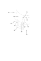
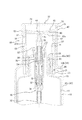
図1は、本発明に従うポンプ付き容器の一実施形態を蓋体の閉鎖姿勢で示す、(a)は平面図であり、(b)は、側面視での断面図であって、図2は、図1(b)の要部拡大図であって、図3は、カバーと蓋体との揺動機構を示す斜視図であって、図4は、図2の状態から蓋体を開放姿勢に変位させてカバーを押圧する状況を示す要部拡大断面図である。
Hereinafter, the present invention will be described more specifically with reference to the drawings.
1 shows one embodiment of a container with a pump according to the present invention in a closed position of a lid, (a) is a plan view, (b) is a cross-sectional view in side view, and FIG. 1B is an enlarged view of the main part of FIG. 1B, FIG. 3 is a perspective view showing a swing mechanism of the cover and the lid, and FIG. 4 is a posture in which the lid is opened from the state of FIG. It is a principal part expanded sectional view which shows the condition which is displaced to and presses a cover.
図1(a)、(b)において、符号10は内容物を収容する容器であり、符号20は容器10に固定保持されるベースキャップであり、符号30は容器10内の内容物を注出させるポンプであり、符号40はカバーであり、符号50は蓋体である。また、後述するようにカバー40の上部には吐出部を設けている。
1 (a) and 1 (b),
本実施形態において容器10は、円板状となる底部11の縁部より円筒状の胴部12が立ち上がり、肩部13を介して胴部12よりも小径となる円筒状の口部14を一体連結したものである。また、口部14の外周面にはねじ部を設けている。
In this embodiment, the
図2に示すようにベースキャップ20は、容器10の口部14を取り囲む円筒状の基部21と、基部21の径方向内側にて水平方向に延在(基部21の上端から径方向に延在)する上壁部22と、上壁部22の径方向内側に設けられ下向き凹状空間を形成する連結部23とを一体連結するものであり、連結部23の径方向内側には表裏を貫通する開口24を設けている。基部21の内周面には、口部14のねじ部に適合するねじ部を設けている。また、上壁部22は、その縁部に上方に向けて延びる環状壁部25を備えている。
As shown in FIG. 2, the
本実施形態においてポンプ30は、上部をベースキャップ20の連結部23に嵌合させて口部14内に吊り下げ保持される円筒状のシリンダー31と、シリンダー31内への内容物の流入、停止を司るポペット弁32と、シリンダー31とポペット弁32との間の環状長手空間内に配置されるコイルバネ33と、コイルバネ33にて上方に付勢されるとともにその内側に内容物の流路を備える管状のピストン保持具34と、ピストン保持具34に連結する管状のステム35と、ステム35の押し込みに伴いシリンダー31内を加圧するピストン36とを備えている。本発明に従うポンプ30は、本実施形態のような構成となるものに限られず、既知の種々のポンプを適用することが可能である。また、シリンダー31の底部には、容器10内の内容物をシリンダー31内に吸い上げるパイプ37を設けている。更に、パッキン38が、口部14と上壁部22とで挟持されている。
In the present embodiment, the
本実施形態におけるカバー40は、ステム35を嵌合保持する円筒状の嵌合筒41をその裏面に備える天面壁42と、天面壁42の縁部に一体連結し少なくともベースキャップ20を取り囲む周壁43とを備えるものであり、天面壁42と周壁43の上部で吐出部を形成し、周壁43の残部がカバー周壁を形成している。本実施形態における吐出部は、天面壁42の上面が、縁部から中央部に向かって下向きに滑らかに湾曲する凹面状となっており、更に中央部には、ステム35の内側に繋がる注出口44が設けられていて、これにより注出した内容物を受け入れる受皿部45を形成している。天面壁42の裏面には、嵌合筒41と周壁43との間を直線状に繋いだ横リブ42aを設けていて、本実施形態では複数の横リブ42aを全体で放射状となるように設けている。また図3に示すようにカバー40には、天面壁42及び周壁43の連結部において、これらの一部を切り取った切り欠き部46を備えている。そして切り欠き部46の端面の両側には、円柱状の軸部47を設けている。
The
また、図2に示すように周壁43は、本実施形態では、天面壁42に一体連結する小径部43aと、小径部43aに段部43bを介して一体連結する大径部43cとで形成されている。
In addition, as shown in FIG. 2, the
蓋体50は、図2に示すように、カバー40の周壁43に連なる外周壁51と、外周壁51の上部を覆う円板状の頂壁52とを備えている。また、図3に示すように外周壁51には、その一部分をカバー40の切り欠き部46に適合するように延ばした延長部53を設けていて、延長部53の両端面には、その一部を内側に凹ませた軸受け部54を設けている。これにより蓋体50は、軸受け部54を軸部47に嵌め込むことで、カバー40に対して揺動可能に保持される。また、延長部53の下方における端部55は、ポンプ30を不用意に作動させないためのストッパーとして機能するものである。この点については後述する。更に、蓋体50には、図2に示すように延長部53の反対側に径方向外側に突き出す指掛かり部56を設けている。なお、カバー40の軸部47と蓋体50の軸受け部54とを、相互に入れ換えて設けてもよい。
As shown in FIG. 2, the
上記のような部材にて構成されるポンプ付き容器は、図2に示すように蓋体50が閉鎖姿勢に変位している時、延長部53の端部55を、ベースキャップ20の一部(本実施形態では環状壁部25の頂部25a)に対し、当接するか、僅かに隙間をあけた所に位置するように設けている。これにより、カバー40や蓋体50を下向きに押圧しても、端部55が環状壁部25の頂部25aに当たるので、ステム35の押し込みが阻止される。
As shown in FIG. 2, the pump-equipped container constituted by the members as described above is configured so that the
なお、本実施形態では環状壁部25の頂部25aに延長部53の端部55が当たるように構成したが、容器のサイズによっては、環状壁部25を省略して延長部53をベースキャップ20の上壁部22まで延ばして、端部55が上壁部22に当たるように構成してもよい。
In the present embodiment, the
一方、図4に示すように蓋体50を開くと、延長部53の内周面が横リブ42aに当接し、蓋体50は開放姿勢に維持される。この場合において、端部55は環状壁部25の頂部25aから離れているので、受皿部45を押圧することで、ステム35が押し込まれてポンプ30を作動させることができる。本実施形態においては、段部43bに指をかけて押し下げたり、周壁43を手のひら全体で掴んで押し下げたりすることもできる。受皿部45内に注出された内容物を、コットンやパフ等の塗布用具にしみ込ませて使用する場合には、塗布用具を受皿部45に載置しておき、その状態のままカバー40を押し下げる操作も可能である。また、カバー40の周壁43がベースキャップ20を取り囲んでいるので、受皿部45から内容物がこぼれてもベースキャップ20側に入り込むことがなく、こぼれた内容物を簡単に拭き取ることができる。なお、ステム35に対するカバー40の下降限位置のストッパーとしては、延長部53の外周面と環状壁部25の頂部25aとの当接や、カバー40における嵌合筒41の先端とベースキャップ20における連結部23の上面との当接、或いは、図1を参照して明らかなようにカバー40の下端と容器10を載置する接地面との当接等を、適宜選択して利用することができる。
On the other hand, when the
次に本発明に従うポンプ付き容器の他の実施形態について、図5を参照しつつ説明する。なお、同一の機能を有する部材については、同一の符号を付してここでは説明を省略する。図5に示すポンプ付き容器は、ベースキャップ20の基部21の外周面に、その相互間に縦溝26を形成する一対のリブ27を設け、カバー40の周壁43の内周面に、縦溝26に適合する1つの縦リブ48を設けたものである(図示の例では、縦溝26と縦リブ48からなる組を2組設けているが、1つ、又は3つ以上設けても良い。)。これによりカバー40は、容器10に対して回り止め保持されるので、容器10に対する蓋体50の向きは常に一定となり、容器10を据え置いて使用する場合に指掛かり部56の向きが意図せず変わってしまうことがなくなる。
Next, another embodiment of the container with a pump according to the present invention will be described with reference to FIG. In addition, about the member which has the same function, the same code | symbol is attached | subjected and description is abbreviate | omitted here. The container with a pump shown in FIG. 5 is provided with a pair of
図2に示す実施形態では、内容物を収容した容器10に対し、ポンプ30を装着したベースキャップ20を取り付け、その後、カバー40を取り付ける必要があるが、図5に示す実施形態では、予め、ポンプ30を装着したベースキャップ20とカバー40とを組み合わせておき、内容物を収容した容器10に対してこれらを1回で取り付けることができるので、組み立て工程が簡単になるという利点がある。
In the embodiment shown in FIG. 2, it is necessary to attach the
なお、これまで述べた実施形態では、注出口44を天面壁42に形成した受皿部45を備えるものとして説明したが、本発明はこのような形態に限定されるものではなく、例えば、受皿部45を設けず、天面壁42を平坦面や膨出面としたり、注出口を吐出部の周壁である周壁43の上部に設けた横向きタイプの吐出部とすることもできる。
In the embodiment described so far, the description has been made assuming that the receiving
本発明によれば、蓋体を閉めておけばポンプを誤って作動させてしまうことがなく、また蓋体を開ければすぐにポンプの操作が可能となるので、使い勝手に優れた、新たなポンプ付き容器を提供することができる。 According to the present invention, if the lid is closed, the pump will not be erroneously operated, and the pump can be operated immediately after the lid is opened. An attached container can be provided.
10 容器
14 口部
20 ベースキャップ
24 開口
25a 環状壁部の頂部(ベースキャップの頂部)
26 縦溝
30 ポンプ
35 ステム
40 カバー
42 天面壁(吐出部の天面壁)
43 周壁(吐出部の周壁とカバー周壁の結合体)
43a 小径部
43b 段部
43c 大径部
44 注出口
45 受皿部
46 切り欠き部
47 軸部
48 縦リブ
50 蓋体
51 外周壁
52 頂壁
53 延長部
54 軸受け部
55 端部
10
26
43 Peripheral wall (combined body of discharge part and cover peripheral wall)
43a
Claims (4)
前記吐出部は、該周壁の上方を閉鎖する天面壁を有し、該天面壁及び周壁の少なくとも一方に内容物の注出口を備えており、
前記カバーは、前記天面壁及び周壁の一部を切り取った切り欠き部を有し、前記蓋体は、該切り欠き部に適合する延長部を備え、
該延長部は、該切り欠き部の端面に設けた軸部又は軸受け部に適合して該蓋体を揺動可能に保持する軸受け部又は軸部を有するとともに、該蓋体の閉鎖姿勢時に前記ベースキャップの一部に対して当接するか僅かに隙間をあけた所に位置してステムに繋がる前記カバーの押し込みを阻止する端部を備える、ポンプ付き容器。 A base cap having an opening connected to the inside of the container and fixedly held at the mouth of the container, and a pump that is suspended and held through the opening and sucks, pressurizes, and pumps the contents by repeatedly pushing and returning the stem. And a cover provided with a discharge portion connected to the stem and at least a cover peripheral wall surrounding the base cap and integrally connected to the peripheral wall of the discharge portion, and a lid provided on the cover,
The discharge part has a top wall that closes above the peripheral wall, and has a spout for contents on at least one of the top wall and the peripheral wall,
The cover has a cutout part obtained by cutting out a part of the top wall and the peripheral wall, and the lid body includes an extension part adapted to the cutout part,
The extension portion has a bearing portion or a shaft portion that fits a shaft portion or a bearing portion provided on an end surface of the notch portion and holds the lid body so as to be swingable. A container with a pump, comprising: an end portion that contacts a part of a base cap or is positioned at a slight gap to prevent pushing of the cover connected to the stem.
Priority Applications (1)
| Application Number | Priority Date | Filing Date | Title |
|---|---|---|---|
| JP2013015773A JP5964255B2 (en) | 2013-01-30 | 2013-01-30 | Container with pump |
Applications Claiming Priority (1)
| Application Number | Priority Date | Filing Date | Title |
|---|---|---|---|
| JP2013015773A JP5964255B2 (en) | 2013-01-30 | 2013-01-30 | Container with pump |
Publications (2)
| Publication Number | Publication Date |
|---|---|
| JP2014144802A JP2014144802A (en) | 2014-08-14 |
| JP5964255B2 true JP5964255B2 (en) | 2016-08-03 |
Family
ID=51425403
Family Applications (1)
| Application Number | Title | Priority Date | Filing Date |
|---|---|---|---|
| JP2013015773A Active JP5964255B2 (en) | 2013-01-30 | 2013-01-30 | Container with pump |
Country Status (1)
| Country | Link |
|---|---|
| JP (1) | JP5964255B2 (en) |
Families Citing this family (1)
| Publication number | Priority date | Publication date | Assignee | Title |
|---|---|---|---|---|
| JP6669578B2 (en) * | 2016-04-28 | 2020-03-18 | 東洋エアゾール工業株式会社 | Actuator |
Family Cites Families (2)
| Publication number | Priority date | Publication date | Assignee | Title |
|---|---|---|---|---|
| JPS63175049U (en) * | 1987-02-14 | 1988-11-14 | ||
| JPH0930548A (en) * | 1995-07-18 | 1997-02-04 | Kao Corp | Ejection device |
-
2013
- 2013-01-30 JP JP2013015773A patent/JP5964255B2/en active Active
Also Published As
| Publication number | Publication date |
|---|---|
| JP2014144802A (en) | 2014-08-14 |
Similar Documents
| Publication | Publication Date | Title |
|---|---|---|
| US20160262523A1 (en) | Cream-type cosmetic container | |
| KR20170006133A (en) | Cosmetic container | |
| JP2011116424A (en) | Container with pump | |
| JP3223051U (en) | Cap with dropper | |
| KR101701311B1 (en) | Pump Container | |
| JP2014193747A (en) | Pouring container | |
| KR200475334Y1 (en) | A cosmetic vessel capable of refill | |
| JP5964255B2 (en) | Container with pump | |
| JP6027327B2 (en) | Dispensing container | |
| JP2015006671A (en) | Stopper for container with pump | |
| JP2015030482A (en) | Teeming container | |
| JP4743389B2 (en) | Small discharge container | |
| JP6320776B2 (en) | Pump type dispenser | |
| JP2013249087A (en) | Attachment for head operation of discharge container | |
| JP6261428B2 (en) | Dropper container | |
| JP2017013844A (en) | Discharge container for discharging content onto discharge surface | |
| JP2020192273A (en) | Discharge container | |
| JP6138707B2 (en) | Pump type dispenser | |
| JP6362968B2 (en) | Pump container with saucer | |
| JP5489536B2 (en) | Container with pump | |
| JP2021031064A (en) | Discharge device | |
| JP6150978B2 (en) | Pump container provided with a head for an extractor and an extractor used therefor | |
| JP2019081570A (en) | Attachment for pump operation and pump container with attachment for pump operation | |
| JP7303501B2 (en) | Injection operation support equipment | |
| CN205131984U (en) | Automatic box -like singlehanded finger pressure bottle lid of lid |
Legal Events
| Date | Code | Title | Description |
|---|---|---|---|
| A621 | Written request for application examination |
Free format text: JAPANESE INTERMEDIATE CODE: A621 Effective date: 20150731 |
|
| A977 | Report on retrieval |
Free format text: JAPANESE INTERMEDIATE CODE: A971007 Effective date: 20160526 |
|
| TRDD | Decision of grant or rejection written | ||
| A01 | Written decision to grant a patent or to grant a registration (utility model) |
Free format text: JAPANESE INTERMEDIATE CODE: A01 Effective date: 20160628 |
|
| A61 | First payment of annual fees (during grant procedure) |
Free format text: JAPANESE INTERMEDIATE CODE: A61 Effective date: 20160629 |
|
| R150 | Certificate of patent or registration of utility model |
Ref document number: 5964255 Country of ref document: JP Free format text: JAPANESE INTERMEDIATE CODE: R150 |