JP5962030B2 - Image forming apparatus - Google Patents
Image forming apparatus Download PDFInfo
- Publication number
- JP5962030B2 JP5962030B2 JP2012015947A JP2012015947A JP5962030B2 JP 5962030 B2 JP5962030 B2 JP 5962030B2 JP 2012015947 A JP2012015947 A JP 2012015947A JP 2012015947 A JP2012015947 A JP 2012015947A JP 5962030 B2 JP5962030 B2 JP 5962030B2
- Authority
- JP
- Japan
- Prior art keywords
- charger
- value
- voltage
- current
- control
- Prior art date
- Legal status (The legal status is an assumption and is not a legal conclusion. Google has not performed a legal analysis and makes no representation as to the accuracy of the status listed.)
- Active
Links
Images


Classifications
-
- G—PHYSICS
- G03—PHOTOGRAPHY; CINEMATOGRAPHY; ANALOGOUS TECHNIQUES USING WAVES OTHER THAN OPTICAL WAVES; ELECTROGRAPHY; HOLOGRAPHY
- G03G—ELECTROGRAPHY; ELECTROPHOTOGRAPHY; MAGNETOGRAPHY
- G03G15/00—Apparatus for electrographic processes using a charge pattern
- G03G15/02—Apparatus for electrographic processes using a charge pattern for laying down a uniform charge, e.g. for sensitising; Corona discharge devices
- G03G15/0283—Arrangements for supplying power to the sensitising device
-
- G—PHYSICS
- G03—PHOTOGRAPHY; CINEMATOGRAPHY; ANALOGOUS TECHNIQUES USING WAVES OTHER THAN OPTICAL WAVES; ELECTROGRAPHY; HOLOGRAPHY
- G03G—ELECTROGRAPHY; ELECTROPHOTOGRAPHY; MAGNETOGRAPHY
- G03G15/00—Apparatus for electrographic processes using a charge pattern
- G03G15/02—Apparatus for electrographic processes using a charge pattern for laying down a uniform charge, e.g. for sensitising; Corona discharge devices
- G03G15/0266—Arrangements for controlling the amount of charge
-
- G—PHYSICS
- G03—PHOTOGRAPHY; CINEMATOGRAPHY; ANALOGOUS TECHNIQUES USING WAVES OTHER THAN OPTICAL WAVES; ELECTROGRAPHY; HOLOGRAPHY
- G03G—ELECTROGRAPHY; ELECTROPHOTOGRAPHY; MAGNETOGRAPHY
- G03G21/00—Arrangements not provided for by groups G03G13/00 - G03G19/00, e.g. cleaning, elimination of residual charge
- G03G21/16—Mechanical means for facilitating the maintenance of the apparatus, e.g. modular arrangements
- G03G21/18—Mechanical means for facilitating the maintenance of the apparatus, e.g. modular arrangements using a processing cartridge, whereby the process cartridge comprises at least two image processing means in a single unit
- G03G21/1875—Mechanical means for facilitating the maintenance of the apparatus, e.g. modular arrangements using a processing cartridge, whereby the process cartridge comprises at least two image processing means in a single unit provided with identifying means or means for storing process- or use parameters, e.g. lifetime of the cartridge
Landscapes
- Physics & Mathematics (AREA)
- Engineering & Computer Science (AREA)
- General Physics & Mathematics (AREA)
- Plasma & Fusion (AREA)
- Computer Vision & Pattern Recognition (AREA)
- Color Electrophotography (AREA)
- Electrostatic Charge, Transfer And Separation In Electrography (AREA)
- Control Or Security For Electrophotography (AREA)
Description
本発明は、感光体を帯電させる帯電器をそれぞれ有し、装置本体に対して着脱可能な複数のカートリッジを備えた画像形成装置に関する。 The present invention relates to an image forming apparatus having a plurality of cartridges each having a charger for charging a photosensitive member and detachable from an apparatus main body.
従来、並列に接続した複数の帯電器に対して1つの共通電源を接続してコストダウンを図る技術が知られている(特許文献1参照)。また、帯電器を備えるプロセスカートリッジ(カートリッジ)が、複数、画像形成装置本体に対して着脱可能に構成された技術も知られている(特許文献2参照)。 2. Description of the Related Art Conventionally, a technique for reducing cost by connecting one common power source to a plurality of chargers connected in parallel is known (see Patent Document 1). There is also known a technique in which a plurality of process cartridges (cartridges) including a charger are configured to be detachable from the image forming apparatus main body (see Patent Document 2).
ところで、出願人は、並列に接続した複数の帯電器に対して1つの電圧印加回路を接続する構成において、各帯電器に流れる電流のうち、最小値となる電流が所定の値となるように複数の帯電器に印加する電圧(電圧印加回路)を制御する画像形成装置を提案している。このような装置において、帯電器を有するカートリッジの1つが装着されていないと、装着されていない位置の電流の値を最小値として当該位置の電流値を上げようとする電圧制御が行われるため、装着されているカートリッジの帯電器に過大な電圧が印加され、帯電器に過電流が流れてしまう可能性がある。 By the way, the applicant, in a configuration in which one voltage application circuit is connected to a plurality of chargers connected in parallel, among the currents flowing through each charger, the current that becomes the minimum value becomes a predetermined value. An image forming apparatus that controls voltages (voltage application circuits) applied to a plurality of chargers has been proposed. In such a device, if one of the cartridges having a charger is not mounted, voltage control is performed to increase the current value at the position with the current value at the position where the charger is not mounted as the minimum value. There is a possibility that an excessive voltage is applied to the charger of the mounted cartridge and an overcurrent flows through the charger.
そこで、本発明は、帯電器に過電流が流れることを抑制することができる画像形成装置を提供することを目的とする。 SUMMARY An advantage of some aspects of the invention is that it provides an image forming apparatus capable of suppressing an overcurrent from flowing through a charger.
前記した目的を達成するため、本発明の画像形成装置は、装置本体と、第1感光体と当該第1感光体を帯電させる第1帯電器とを有し、装置本体に対して着脱可能な第1カートリッジと、第2感光体と当該第2感光体を帯電させる第2帯電器とを有し、装置本体に対して着脱可能な第2カートリッジと、第1帯電器および当該第1帯電器と並列に接続された第2帯電器に電圧を印加する電圧印加手段と、装置本体に対して第1カートリッジおよび第2カートリッジが装着されているか否かを判定可能な装着判定手段と、第1帯電器および第2帯電器に印加する電圧の値が所定電圧値となるように電圧印加手段を制御する定電圧制御と、第1帯電器に流れる電流および第2帯電器に流れる電流のうち最小値となる電流が所定電流値となるように電圧印加手段を制御する定電流制御とを実行可能な制御手段とを備える。
そして、制御手段は、印刷準備のための初期動作の開始時に定電圧制御を実行し、装着判定手段がすべてのカートリッジが装着されていると判定した場合に定電圧制御から定電流制御に切り替える。
In order to achieve the above-described object, an image forming apparatus of the present invention includes an apparatus main body, a first photosensitive member, and a first charger that charges the first photosensitive member, and is detachable from the apparatus main body. A second cartridge that has a first cartridge, a second photosensitive member, and a second charger that charges the second photosensitive member, and is attachable to and detachable from the apparatus main body; a first charger; and the first charger. Voltage applying means for applying a voltage to a second charger connected in parallel with the battery, mounting determination means for determining whether or not the first cartridge and the second cartridge are mounted on the apparatus main body, and a first Constant voltage control for controlling the voltage application means so that the value of the voltage applied to the charger and the second charger becomes a predetermined voltage value, and the minimum of the current flowing through the first charger and the current flowing through the second charger So that the current value becomes the predetermined current value And a viable control means and a constant current control for controlling the voltage application means.
The control unit executes constant voltage control at the start of the initial operation for preparing for printing, and switches from constant voltage control to constant current control when the mounting determination unit determines that all cartridges are mounted.
この構成によれば、印刷準備のための初期動作の開始時に定電圧制御、すなわち帯電器に印加する電圧を一定とする制御を実行するので、カートリッジの例えば1つが装着されていない場合に帯電器に印加する電圧が上昇するというようなことがなくなる。これにより、装着されているカートリッジの帯電器に過電流が流れることを抑制することができる。 According to this configuration, constant voltage control is performed at the start of the initial operation for preparing for printing, that is, control to make the voltage applied to the charger constant, so that the charger is charged when, for example, one of the cartridges is not mounted. The voltage applied to is not increased. As a result, it is possible to suppress an overcurrent from flowing through the charger of the mounted cartridge.
前記した画像形成装置において、制御手段は、装着判定手段がすべてのカートリッジが装着されていると判定した場合、定電圧制御から定電流制御への切り替えを初期動作中に実行するように構成することが望ましい。 In the image forming apparatus described above, the control unit is configured to perform switching from constant voltage control to constant current control during the initial operation when the mounting determination unit determines that all the cartridges are mounted. Is desirable.
これによれば、定電圧制御から定電流制御への切り替えを初期動作中に実行することで、定電圧制御から定電流制御への切り替えを初期動作終了後に実行する場合と比較して、画像形成装置が印刷可能な状態となるまでに要する時間を短縮化することができる。 According to this, the switching from the constant voltage control to the constant current control is performed during the initial operation, so that the image formation is performed as compared with the case where the switching from the constant voltage control to the constant current control is performed after the initial operation is completed. The time required for the apparatus to be ready for printing can be shortened.
前記した各画像形成装置において、装着判定手段は、定電圧制御中に、第1帯電器に流れる電流および第2帯電器に流れる電流を個別に取得し、取得した電流値が第1基準値以下である場合は、対応する帯電器を有しているカートリッジが装着されていないと判定し、取得した電流値が第1基準値を超える場合は、対応する帯電器を有するカートリッジが装着されていると判定するように構成することができる。 In each of the image forming apparatuses described above, the attachment determination unit individually acquires the current flowing through the first charger and the current flowing through the second charger during the constant voltage control, and the acquired current value is equal to or less than the first reference value. If it is determined that the cartridge having the corresponding charger is not mounted, and the acquired current value exceeds the first reference value, the cartridge having the corresponding charger is mounted. Can be configured.
これによれば、装置本体内にカートリッジの有無を検出するためのセンサを設けなくても、カートリッジが装着されているか否かを判定することができる。これにより、部品点数の削減や低コスト化、装置の小型化などが可能となる。 According to this, it is possible to determine whether or not a cartridge is mounted without providing a sensor for detecting the presence or absence of the cartridge in the apparatus main body. As a result, the number of parts can be reduced, the cost can be reduced, and the size of the apparatus can be reduced.
また、本発明の画像形成装置において、制御手段は、定電圧制御を実行するときに所定電圧値を少なくとも第1の電圧値と当該第1の電圧値とは異なる第2の電圧値とに切り替えるように構成することができる。
この場合、装着判定手段は、定電圧制御中に、第1帯電器に流れる電流および第2帯電器に流れる電流を個別に取得し、第1の電圧値の電圧が印加されているときに取得した第1の電流値と、第2の電圧値の電圧が印加されているときに取得した第2の電流値との差が第2基準値以下である場合は、対応する帯電器を有しているカートリッジが装着されていないと判定し、第1の電流値と第2の電流値との差が第2基準値を超える場合は、対応する帯電器を有するカートリッジが装着されていると判定するように構成することができる。
In the image forming apparatus of the present invention, the control unit switches the predetermined voltage value to at least the first voltage value and the second voltage value different from the first voltage value when performing the constant voltage control. It can be constituted as follows.
In this case, during the constant voltage control, the mounting determination unit individually acquires the current flowing through the first charger and the current flowing through the second charger, and acquires when the voltage of the first voltage value is applied. If the difference between the first current value obtained and the second current value obtained when the voltage of the second voltage value is applied is equal to or less than the second reference value, a corresponding charger is provided. If the difference between the first current value and the second current value exceeds the second reference value, it is determined that the cartridge having the corresponding charger is installed. Can be configured to.
これによれば、装置本体内にカートリッジの有無を検出するためのセンサを設けなくても、カートリッジが装着されているか否かを判定することができる。特に、取得した電流値自体ではなく、第1の電流値と第2の電流値との差からカートリッジが装着されているか否かを判定するので、仮にもともと電流が流れにくい帯電器があったとしても、カートリッジが装着されているか否かを精度良く判定することができる。また、カートリッジの有無を検出するセンサを設ける必要がなくなるため、部品点数の削減や低コスト化、装置の小型化などが可能となる。 According to this, it is possible to determine whether or not a cartridge is mounted without providing a sensor for detecting the presence or absence of the cartridge in the apparatus main body. In particular, since it is determined whether or not the cartridge is mounted based on the difference between the first current value and the second current value, rather than the acquired current value itself, it is assumed that there was a charger that does not easily flow current. In addition, it is possible to accurately determine whether or not a cartridge is mounted. Further, since it is not necessary to provide a sensor for detecting the presence / absence of a cartridge, the number of parts can be reduced, the cost can be reduced, and the apparatus can be downsized.
前記した各画像形成装置において、制御手段は、装着判定手段がブラックに対応する第1カートリッジが装着され、ブラック以外の色に対応する第2カートリッジが装着されていないと判定し、かつ、印刷データが入力された場合は、第1カートリッジを用いたモノクロ印刷動作を定電圧制御で実行するように構成することができる。 In each of the image forming apparatuses described above, the control unit determines that the mounting determination unit has mounted the first cartridge corresponding to black and that the second cartridge corresponding to a color other than black has not been mounted, and print data. Can be configured to execute a monochrome printing operation using the first cartridge with constant voltage control.
これによれば、ブラック以外の色に対応する第2カートリッジ、例えば、マゼンタのカートリッジが装着されていない場合においても、モノクロ印刷は可能としつつ、ブラックやシアン、イエローのカートリッジの帯電器に過電流が流れることを抑制することができる。 According to this, even when a second cartridge corresponding to a color other than black, for example, a magenta cartridge is not mounted, monochrome printing is possible, but an overcurrent is applied to the chargers of the black, cyan, and yellow cartridges. Can be prevented from flowing.
前記した各画像形成装置においては、報知手段を備え、制御手段は、装着判定手段が少なくとも1つのカートリッジが装着されていないと判定した場合に報知手段にエラーを報知させるように構成することができる。Each of the image forming apparatuses described above includes a notification unit, and the control unit can be configured to cause the notification unit to notify an error when the mounting determination unit determines that at least one cartridge is not mounted. .
これによれば、カートリッジが装着されていない旨の情報をユーザに対して報知することができる。According to this, it is possible to notify the user that the cartridge is not mounted.
また、前記した目的を達成するため、本発明の画像形成装置は、装置本体と、第1感光体と当該第1感光体を帯電させる第1帯電器とを有し、装置本体に対して着脱可能な第1カートリッジと、第2感光体と当該第2感光体を帯電させる第2帯電器とを有し、装置本体に対して着脱可能な第2カートリッジと、第1帯電器および当該第1帯電器と並列に接続された第2帯電器に電圧を印加する電圧印加手段と、制御手段とを備える。In order to achieve the above-described object, the image forming apparatus of the present invention includes an apparatus main body, a first photosensitive member, and a first charger for charging the first photosensitive member, and is attached to and detached from the apparatus main body. A second cartridge that can be attached to and detached from the apparatus main body, the first charger, and the first charger. Voltage application means for applying a voltage to a second charger connected in parallel with the charger, and control means are provided.
そして、制御手段は、第1帯電器および第2帯電器に印加する電圧の値が所定電圧値となるように電圧印加手段を制御して第1帯電器に流れる電流および第2帯電器に流れる電流を個別に取得し、取得した各電流値が第1基準値を超える場合は、第1帯電器に流れる電流および第2帯電器に流れる電流のうち最小値となる電流が所定電流値となるように電圧印加手段を制御する。 Then, the control means controls the voltage application means so that the value of the voltage applied to the first charger and the second charger becomes a predetermined voltage value, and flows the current flowing through the first charger and the second charger. When the current is acquired individually and each acquired current value exceeds the first reference value, the current that becomes the minimum value among the current that flows through the first charger and the current that flows through the second charger becomes the predetermined current value. Thus, the voltage application means is controlled.
この構成によれば、まず、帯電器に印加する電圧を一定とする制御を実行するので、カートリッジの例えば1つが装着されていない場合に帯電器に印加する電圧が上昇するというようなことがなくなる。これにより、装着されているカートリッジの帯電器に過電流が流れることを抑制することができる。According to this configuration, first, the control to make the voltage applied to the charger constant is executed, so that the voltage applied to the charger does not increase when, for example, one of the cartridges is not mounted. . As a result, it is possible to suppress an overcurrent from flowing through the charger of the mounted cartridge.
前記した画像形成装置において、制御手段は、印刷準備のための初期動作の開始時に第1帯電器および第2帯電器に印加する電圧の値が所定電圧値となるように電圧印加手段を制御して第1帯電器に流れる電流および第2帯電器に流れる電流を個別に取得し、取得した各電流値が第1基準値を超える場合は、印刷動作時に第1帯電器に流れる電流および第2帯電器に流れる電流のうち最小値となる電流が所定電流値となるように電圧印加手段を制御するように構成することができる。In the above-described image forming apparatus, the control unit controls the voltage application unit so that the value of the voltage applied to the first charger and the second charger at the start of the initial operation for preparing for printing becomes a predetermined voltage value. When the current value flowing through the first charger and the current flowing through the second charger are individually acquired and the acquired current values exceed the first reference value, the current flowing through the first charger and the second current during the printing operation are obtained. The voltage application unit can be configured so that the current that becomes the minimum value among the currents flowing through the charger becomes a predetermined current value.
本発明によれば、印刷準備のための初期動作の開始時には定電圧制御を実行し、すべてのカートリッジが装着されていると判定された場合に定電圧制御から定電流制御に切り替えるので、帯電器に過電流が流れることを抑制することができる。 According to the present invention, the constant voltage control is executed at the start of the initial operation for printing preparation, and when it is determined that all the cartridges are mounted, the constant voltage control is switched to the constant current control. Overcurrent can be suppressed.
次に、本発明の一実施形態について、適宜図面を参照しながら詳細に説明する。なお、以下の説明では、まず、画像形成装置の一例としてのカラープリンタ1の概略構成を説明した後、本発明の特徴部分に係るカラープリンタ1の詳細な構成について説明する。
Next, an embodiment of the present invention will be described in detail with reference to the drawings as appropriate. In the following description, first, a schematic configuration of the
また、以下の説明において、方向は、カラープリンタ1を使用するユーザを基準にした方向で説明する。すなわち、図1における左側を「前」、右側を「後」とし、手前側を「右」、奥側を「左」とする。また、図1における上下方向を「上下」とする。
In the following description, the direction will be described with reference to the user who uses the
<カラープリンタの全体構成>
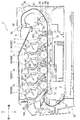
図1に示すように、カラープリンタ1は、装置本体の一例としての本体筐体10と、アッパーカバー11と、用紙Sを供給する給紙部20と、供給された用紙Sに画像を形成する画像形成部30と、画像が形成された用紙Sを排出する排紙部90とを主に備えている。
<Overall configuration of color printer>
As shown in FIG. 1, the
アッパーカバー11は、本体筐体10の上部に設けられ、後側の回動軸12を中心として前側が本体筐体10に対し上下に回動することで、本体筐体10の上面に形成された開口10Aを開閉する。開口10Aは、本体筐体10の内部に収容された部材をメンテナンスするための開口である。
The
なお、内部に収容された部材のメンテナンスの具体例としては、後述するプロセスカートリッジ50(帯電器52)などを新しいものに交換することや、帯電器52(ワイヤ電極521)をクリーニングすることなどを挙げることができる。ちなみに、帯電器52をクリーニングするための具体的な方法や構成などは公知であるので、本明細書においては詳細な説明を省略する。
Specific examples of the maintenance of the members accommodated in the interior include replacement of a process cartridge 50 (charger 52) described later with a new one, cleaning of the charger 52 (wire electrode 521), and the like. Can be mentioned. Incidentally, since a specific method and configuration for cleaning the
給紙部20は、本体筐体10内の下部に設けられ、用紙Sを収容する給紙トレイ21と、給紙トレイ21から用紙Sを画像形成部30に供給する用紙供給機構22とを主に備えている。給紙トレイ21内の用紙Sは、用紙供給機構22によって1枚ずつ分離されて画像形成部30に供給される。
The
画像形成部30は、4つのLEDユニット40と、4つのカートリッジの一例としてのプロセスカートリッジ50と、転写ユニット70と、定着ユニット80とを主に備えて構成されている。
The
LEDユニット40は、アッパーカバー11に保持部14を介して揺動可能に支持されており、アッパーカバー11を閉じた状態において感光体ドラム51の上方に対向して配置される。このLEDユニット40は、画像データに基づいて先端の発光部(LED)が明滅することで、帯電後の感光体ドラム51の表面を露光する。
The
プロセスカートリッジ50は、アッパーカバー11と給紙トレイ21との間で前後方向に沿って並列配置されており、アッパーカバー11を開いたときに露出する本体筐体10の開口10Aから、本体筐体10に対し略上下方向に着脱(交換)可能に装着される構成となっている。
The
プロセスカートリッジ50は、感光体の一例としての感光体ドラム51と、帯電器52と、現像ローラ53と、供給ローラ54と、層厚規制ブレード55と、正帯電性のトナー(現像剤)を収容するトナー収容部56とを主に備えている。
The
プロセスカートリッジ50は、ブラック用、イエロー用、マゼンタ用およびシアン用の各色のトナーが入った50K,50Y,50M,50Cの符号で示すものが用紙Sの搬送方向上流からこの順で並んで配置されている。なお、本明細書および図面において、トナーの色に対応した感光体ドラム51、帯電器52などを特定する場合には、ブラック、イエロー、マゼンタ、シアンのそれぞれに対応させて、K、Y、M、Cの記号を付することとする。
In the
感光体ドラム51は、導電性を有する円筒状のドラム本体の表面(外周面)に感光層が形成されるとともに、ドラム本体に導通する回転軸が接地(図2参照)された公知の感光体である。
The
帯電器52は、各感光体ドラム51に対応して設けられており、ワイヤ電極521と、グリッド電極522とを主に有している。この帯電器52は、帯電バイアス(電圧)が印加されることでコロナ放電を発生させ、対応する感光体ドラム51の表面を正の電位に帯電させる。
The
転写ユニット70は、給紙トレイ21とプロセスカートリッジ50との間に設けられ、駆動ローラ71と、従動ローラ72と、駆動ローラ71と従動ローラ72の間に張設された無端状の搬送ベルト73と、4つの転写ローラ74とを主に備えている。搬送ベルト73は、外側の面が各感光体ドラム51に接しており、その内側には各転写ローラ74が各感光体ドラム51との間で搬送ベルト73を挟持するように配置されている。
The
定着ユニット80は、プロセスカートリッジ50および転写ユニット70の後方に設けられ、加熱ローラ81と、加熱ローラ81と対向配置されて加熱ローラ81を押圧する加圧ローラ82とを主に備えている。
The fixing
画像形成部30では、感光体ドラム51の表面が、帯電器52により一様に帯電された後、LEDユニット40により露光されることで、感光体ドラム51上に画像データに基づく静電潜像が形成される。
In the
また、トナー収容部56内のトナーは、供給ローラ54を介して現像バイアスが印加された現像ローラ53に供給され、現像ローラ53と層厚規制ブレード55との間に進入して一定厚さの薄層として現像ローラ53上に担持される。なお、このような過程において、トナーは、現像ローラ53と供給ローラ54の間や、現像ローラ53と層厚規制ブレード55の間などで正に摩擦帯電される。
Further, the toner in the
そして、現像ローラ53上に担持されたトナーが感光体ドラム51の露光部分に供給されることで、静電潜像が可視像化され、感光体ドラム51上にトナー像が形成される。その後、給紙部20から供給された用紙Sが、感光体ドラム51と搬送ベルト73(転写バイアスが印加された転写ローラ74)の間を搬送されることで、感光体ドラム51上に形成されたトナー像が用紙S上に転写される。トナー像が転写された用紙Sは、加熱ローラ81と加圧ローラ82の間を搬送されることでトナー像が熱定着される。
The toner carried on the developing roller 53 is supplied to the exposed portion of the
なお、カラープリンタ1において、カラー画像を形成する場合は、すべてのプロセスカートリッジ50の感光体ドラム51にトナー像が形成され、用紙Sが感光体ドラム51と搬送ベルト73の間を搬送されるときに、各色のトナー像が用紙S上に順次重ね合わせて転写される。一方、ブラックのトナーのみでモノクロ画像を形成する場合は、ブラックのトナーを収容するプロセスカートリッジ50の感光体ドラム51のみにトナー像が形成され、用紙Sが感光体ドラム51と搬送ベルト73の間を搬送されるときに、ブラックのトナー像が用紙S上に転写される。
When a color image is formed in the
排紙部90は、定着ユニット80から搬出された用紙Sを案内するための排紙経路91と、用紙Sを搬送する複数の搬送ローラ92とを主に備えている。トナー像が熱定着された用紙S(画像が形成された用紙S)は、搬送ローラ92によって排紙経路91を搬送され、本体筐体10の外部に排出されて排紙トレイ13上に載置される。
The
<カラープリンタの詳細構成>
図2に示すように、カラープリンタ1は、帯電バイアス印加装置110と、接離機構200と、制御手段の一例としての制御装置130と、報知手段150とをさらに備えている。
<Detailed configuration of color printer>
As shown in FIG. 2, the
なお、本実施形態では、ブラックのトナーを収容するプロセスカートリッジ50K、感光体ドラム51Kおよび帯電器52Kが、「第1カートリッジ」、「第1感光体」および「第1帯電器」に相当する。また、ブラック以外の色、すなわち、イエロー、マゼンタ、シアンのトナーを収容するプロセスカートリッジ50Y,50M,50C、感光体ドラム51Y,51M,51Cおよび帯電器52Y,52M,52Cが、「第2カートリッジ」、「第2感光体」および「第2帯電器」に相当する。
In the present embodiment, the
帯電バイアス印加装置110は、電圧印加手段の一例としての帯電バイアス印加回路111と、4つの定電圧回路D1,D2,D3,D4と、4つの電流検出部R1,R2,R3,R4とを主に備えて構成されている。
The charging
帯電バイアス印加回路111は、並列に接続された4つのワイヤ電極521に接続されており、各ワイヤ電極521に共通の帯電バイアス(電圧)を印加する回路である。なお、ワイヤ電極521に帯電バイアスを印加する回路の具体的な構成などは公知であるので、本明細書においては詳細な説明を省略する。
The charging
定電圧回路D1〜D4は、例えば、直列に接続された3つのツェナーダイオードから構成されており、各帯電器52のグリッド電極522に印加する電圧を定電圧化する回路である。また、電流検出部R1〜R4は、例えば、抵抗器から構成されており、一端が対応する定電圧回路D1〜D4に接続されるとともに、他端が接地されている。
The constant voltage circuits D <b> 1 to D <b> 4 are constituted by, for example, three Zener diodes connected in series, and are circuits that make the voltage applied to the
接離機構200は、本体筐体10に装着されているプロセスカートリッジ50の感光体ドラム51に対して、対応する現像ローラ53を接触または離間させる公知の機構である。この接離機構200は、例えば、ブラックのトナーのみでモノクロ画像を形成する場合に制御装置130によって駆動され、感光体ドラム51Y,51M,51Cから、対応する現像ローラ53Y,53M,53Cを離間させる。これにより、画像形成(モノクロ印刷)に用いない現像ローラ53Y,53M,53Cから、対応する感光体ドラム51Y,51M,51Cにトナーが移るのを抑えることができるので、用紙Sの汚れを抑制することができる。
The contact / separation mechanism 200 is a known mechanism that causes the corresponding developing roller 53 to contact or separate from the
制御装置130は、図示しないCPU、RAM、ROM、入出力インターフェースなどを備えて構成されており、予め設定されたプログラムなどに従ってカラープリンタ1の各部、例えば、画像形成部30や帯電バイアス印加装置110などを制御する。
The
この制御装置130は、開かれた状態のアッパーカバー11が閉じられたことを図示しないセンサが検知したときにカラープリンタ1を起動し、画像形成部30などを駆動させてトナー収容部56内のトナーを撹拌したり、加熱ローラ81を加熱したりする、ウォーミングアップ動作(印刷準備のための初期動作)を開始するように構成されている。なお、ウォーミングアップ動作は、カラープリンタ1が印刷可能な状態となるまでの動作であり、例えば、加熱ローラ81の表面温度がトナー像の熱定着に適した温度となるまでなどである。
The
制御装置130は、本発明に関連する機能部として、帯電電流検知手段131と、帯電バイアス制御手段132と、装着判定手段133と、印刷制御手段135と、記憶部139とを主に備えている。
The
帯電電流検知手段131は、4つの各ワイヤ電極521に流れた帯電電流を個別に検知する機能を有している。具体的に、帯電電流検知手段131は、配線を介し、各定電圧回路D1〜D4と、当該定電圧回路D1〜D4に対応する電流検出部R1〜R4との間に接続されており、各ワイヤ電極521に流れた帯電電流(詳しくは、各グリッド電極522に流れた電流)の大きさに比例した電圧が入力されるようになっている。これにより、帯電電流検知手段131は、入力された電圧を読み取ることで、各ワイヤ電極521に流れた帯電電流を検知することができるようになっている。
The charging
このように4つの各ワイヤ電極521に流れた帯電電流を個別に検知できることで、後述するように、ワイヤ電極521を有するプロセスカートリッジ50の装着の有無を制御装置130で個別に(色ごとに)把握することが可能となっている。
Since the charging currents flowing through the four
帯電バイアス制御手段132は、帯電バイアス印加回路111を制御することで、各帯電器52に印加する帯電バイアスを制御する機能を有している。具体的に、帯電バイアス制御手段132は、帯電バイアス印加回路111の制御において、定電圧制御と定電流制御とを実行可能に構成されている。
The charging
定電圧制御は、各帯電器52に印加する帯電バイアスの値が後述する所定バイアス値(所定電圧値)となるように帯電バイアス印加回路111を制御するものである。また、定電流制御は、各帯電器52に流れた帯電電流のうち、最小値となる電流が所定電流値となるように帯電バイアス印加回路111を制御するものである。
The constant voltage control is to control the charging
なお、各帯電器52に流れた帯電電流のうち最小値となる電流が所定電流値となるように帯電バイアス印加回路111を制御する、定電流制御を実行することで、帯電後のすべての感光体ドラム51の表面電位を所望の値以上に維持することができる。これにより、特に、印刷のときに、露光部分と未露光部分との電位差をある程度大きくできるため、未露光部分へのトナーの付着を抑制することができ、いわゆるかぶりなどの画像品質の低下を抑制することができる。
It should be noted that by performing constant current control that controls the charging
本実施形態において、帯電バイアス制御手段132は、ウォーミングアップ動作の開始時に、帯電バイアス印加回路111を制御して定電圧制御を実行する。定電圧制御を実行するとき、帯電バイアス制御手段132は、所定バイアス値を、第1バイアス値(第1の電圧値)と、第1バイアス値とは異なる第2バイアス値(第2の電圧値)とに切り替えるように構成されている。
In the present embodiment, the charging
具体的に、帯電バイアス制御手段132は、ウォーミングアップ動作の開始時に、まず、各帯電器52(各ワイヤ電極521)に対し、所定バイアス値として、記憶部139から取得した前回印加した帯電バイアスの値(前回バイアス値)よりも絶対値が小さい第1バイアス値で帯電バイアスを印加するように帯電バイアス印加回路111を制御する。
Specifically, at the start of the warm-up operation, the charging
次いで、帯電バイアス制御手段132は、ウォーミングアップ動作中の、第1バイアス値での帯電バイアスの印加開始時から所定時間経過後に、所定バイアス値として、第1バイアス値よりも絶対値が小さい第2バイアス値で帯電バイアスを印加するように帯電バイアス印加回路111を制御する。なお、帯電電流検知手段131は、第1バイアス値での帯電バイアスの印加によって各ワイヤ電極521に流れた帯電電流を個別に検知して記憶部139に記憶させ、また、第2バイアス値での帯電バイアスの印加によって各ワイヤ電極521に流れた帯電電流を個別に検知して記憶部139に記憶させる。
Next, the charging bias control means 132 is a second bias whose absolute value is smaller than the first bias value as the predetermined bias value after a predetermined time has elapsed since the start of applying the charging bias at the first bias value during the warm-up operation. The charging
なお、第1バイアス値は、実験やシミュレーションなどによって予め定めた固定値、または、予め設定した計算式に基づいて設定すればよい。固定値としては、例えば、印刷制御時に印加される電圧の最小値(各ワイヤ電極521がすべて新品状態であるときに印加される電圧値)よりも小さい値などを採用することができる。また、計算式に基づく値としては、例えば、前回バイアス値の70〜80%程度の値を採用することができる。同様に、第2バイアス値も、予め定めた固定値、または、予め設定した計算式に基づいて設定すればよい。
Note that the first bias value may be set based on a fixed value determined in advance by experiment, simulation, or the like, or a preset calculation formula. As the fixed value, for example, a value smaller than the minimum value of the voltage applied at the time of printing control (the voltage value applied when all the
定電圧制御の開始後、帯電バイアス制御手段132は、装着判定手段133が本体筐体10に対してすべてのプロセスカートリッジ50が装着されていると判定した場合には、帯電バイアス印加回路111の制御を定電圧制御から定電流制御に切り替える。帯電バイアス制御手段132は、装着判定手段133がすべてのカートリッジが装着されていると判定した場合の定電圧制御から定電流制御への切り替えをウォーミングアップ動作中に実行する。
After the start of the constant voltage control, the charging
また、帯電バイアス制御手段132は、印刷制御における所定のタイミングごとに、各帯電器52に印加した帯電バイアスの値を、それぞれ前回値(前回バイアス値)として記憶部139に記憶させる機能を有している。ここで、印刷制御における所定のタイミングとは、例えば、1枚の用紙Sに画像が形成されるたびであってもよいし、カラープリンタ1に入力された1印刷ジョブの処理が終了するたびであってもよい。また、印刷制御における所定のタイミングは、入力された印刷ジョブの処理がすべて終了したとき(印刷終了時)であってもよいし、各帯電器52に印加する帯電バイアスの値が変化したときであってもよい。
Further, the charging
装着判定手段133は、本体筐体10に対して各プロセスカートリッジ50が装着されているか否かを判定する機能を有している。具体的に、装着判定手段133は、定電圧制御中に、各帯電器52に流れた帯電電流を個別に取得し、色ごとに、それぞれ、第1バイアス値の帯電バイアスが印加されているときに取得した第1帯電電流値(第1の電流値)と、第2バイアス値の帯電バイアスが印加されているときに取得した第2帯電電流値(第2の電流値)との差(絶対値)が、予め設定した装着判定基準値(第2基準値)以下であるか否かを判定する。
The
そして、第1帯電電流値と第2帯電電流値との差が装着判定基準値以下である場合、装着判定手段133は、対応する帯電器52を有しているプロセスカートリッジ50が装着されていないと判定し、第1帯電電流値と第2帯電電流値との差が装着判定基準値を超える場合、装着判定手段133は、対応する帯電器52を有するプロセスカートリッジ50が装着されていると判定する。
When the difference between the first charging current value and the second charging current value is equal to or smaller than the mounting determination reference value, the mounting
ここで、装着判定手段133における、プロセスカートリッジ50が装着されているか否かを判定するための原理について説明する。
プロセスカートリッジ50K,50Y,50Cが装着されている場合、帯電器52K,52Y,52Cに印加された帯電バイアスと流れた帯電電流とは、図3に符号52K,52Y,52Cを付して示すグラフのような関係となる。そのため、例えば、第1バイアス値V1の印加によって帯電器52Kに流れた第1帯電電流値AK1と、第2バイアス値V2の印加によって流れた第2帯電電流値AK2との差ΔAKはある程度の大きな値となる。
Here, the principle for determining whether or not the
When the
一方、プロセスカートリッジ50M(帯電器52M)が装着されていない場合、帯電バイアスを印加しても帯電電流は流れないため、帯電電流検知手段131で、第1バイアス値V1の印加によって検知される第1帯電電流値と、第2バイアス値V2の印加によって検知される第2帯電電流値は、いずれも0(詳しくは、帯電電流検知手段131で検知可能な下限値)となる。そのため、第1帯電電流値と第2帯電電流値との差は、上記した差ΔAKよりも小さい値(0に近い値)となる。
On the other hand, when the
本実施形態では、以上のような傾向を踏まえて装着判定基準値を設定し、第1帯電電流値と第2帯電電流値との差が装着判定基準値以下である場合(差が小さい場合)、対応するプロセスカートリッジ50が装着されていないと判定し、第1帯電電流値と第2帯電電流値との差が装着判定基準値を超える場合(差が大きい場合)、対応するプロセスカートリッジ50が装着されていると判定している。
In the present embodiment, the attachment determination reference value is set based on the above tendency, and the difference between the first charging current value and the second charging current value is equal to or less than the attachment determination reference value (when the difference is small). When it is determined that the
装着判定手段133は、プロセスカートリッジ50が装着されていないと判定したときは、そのことを示す情報を報知手段150に出力する。これにより、報知手段150では、プロセスカートリッジ50が装着されていない旨の情報がユーザに対して報知される。
When it is determined that the
印刷制御手段135は、帯電バイアス印加回路111や給紙部20、画像形成部30などを制御することで、印刷動作(用紙Sに画像を形成する動作)を制御する機能を有している。具体的に、印刷制御手段135は、装着判定手段133がすべてのプロセスカートリッジ50が装着されていると判定した状況で、カラープリンタ1に画像データ(印刷データ)が入力されたときは、通常の印刷制御、すなわち、カラー印刷動作またはモノクロ印刷動作を定電流制御で実行する。
The
また、印刷制御手段135は、装着判定手段133がブラックに対応するプロセスカートリッジ50Kが装着され、ブラック以外の色に対応するプロセスカートリッジ50Y,50M,50Cのうちの少なくとも1つが装着されていないと判定した状況で、画像データが入力された場合は、プロセスカートリッジ50Kを用いたモノクロ印刷動作を定電圧制御で実行する。
Further, the
このとき、印刷制御手段135は、接離機構200を駆動して、図4に示すように、ブラック以外の本体筐体10に装着されているプロセスカートリッジ50Y,50Cの現像ローラ53Y,53Cを、対応する感光体ドラム51Y,51Cから離間させる制御を実行する。なお、図4は、一例として、マゼンタに対応するプロセスカートリッジ50Mが装着されていない状態を示している。
At this time, the
なお、詳細な構成についての説明は省略するが、印刷制御手段135は、モノクロ印刷動作を定電圧制御で実行するとき、帯電器52Kに印加する帯電バイアスに応じて、現像ローラ53Kに印加する現像バイアスの値や、転写ローラ74に印加する転写バイアスの値などを適宜制御する。
Although a detailed description of the configuration is omitted, the
報知手段150は、主に、カラープリンタ1を使用するユーザに対してプロセスカートリッジ50が装着されていないことを示す情報を報知する機能を有している。本実施形態において、報知手段150は、どのプロセスカートリッジ50が装着されていないのかを個別に報知することができるように構成されている。
The
図示は省略するが、報知手段150は、例えば、4つのプロセスカートリッジ50に対応して本体筐体10などに設けられた4つのLEDランプとして構成することができ、LEDランプの点灯(または消灯)によって、どのプロセスカートリッジ50が装着されていないのかを個別に報知することができる。また、報知手段150は、本体筐体10などに設けられた液晶ディスプレイとして構成することができ、装着されていないプロセスカートリッジ50の色の名前を表示することで、どのプロセスカートリッジ50が装着されていないのかを個別に報知することができる。また、報知手段150は、音声によって情報を報知するように構成されていてもよい。
Although not shown, the
次に、制御装置130の制御について、図5に示すフローチャートを用いて詳細に説明する。
Next, the control of the
図5に示すように、開かれた状態のアッパーカバー11が閉じられた場合(S21,Yes)、制御装置130は、カラープリンタ1を起動してウォーミングアップ動作を開始し(S22)、定電圧制御を実行する(S23)。このとき、制御装置130は、まず、印刷終了時に記憶した前回バイアス値よりも小さい第1バイアス値を各ワイヤ電極521に印加し、所定時間経過後、第1バイアス値よりも小さい第2バイアス値を各ワイヤ電極521に印加する。
As shown in FIG. 5, when the opened
定電圧制御の開始後、制御装置130は、各グリッド電極522から帯電電流(第1帯電電流値および第2帯電電流値)を取得し(S24)、取得した帯電電流の値に基づいて、すべてのプロセスカートリッジ50が装着されているか否かを判定する(S25,S26)。具体的に、ステップS25では、ブラックのプロセスカートリッジ50Kが装着されているか否かを判定し、ステップS26では、ブラック以外のプロセスカートリッジ50Y,50M,50Cがすべて装着されているか否かを判定する。
After the start of the constant voltage control, the
そして、すべてのプロセスカートリッジ50が装着されていると判定した場合(S25,YesかつS26,Yes)、制御装置130は、ウォーミングアップ動作中に、帯電バイアス印加回路111の制御を定電圧制御から定電流制御に切り替える(S27)。その後、制御装置130は、カラープリンタ1に印刷ジョブ(画像データ)が入力されているか否かを判定する(S28)。
If it is determined that all the
画像データが入力されていなかった場合(S28,No)、制御装置130は、図5に示すフローチャートの処理を終了する。また、画像データが入力されていた場合(S28,Yes)、制御装置130は、定電流制御で印刷動作を実行し(S29)、印刷が終了した場合、処理を終了する。なお、入力されていた画像データが、モノクロ画像の画像データであった場合、制御装置130は、接離機構200を駆動させて、感光体ドラム51Y,51M,51Cから、対応する現像ローラ53Y,53M,53Cを離間させる。これにより、用紙Sの汚れを抑制することができる。
When the image data has not been input (S28, No), the
一方、ステップS25において、ブラックのプロセスカートリッジ50Kが装着されていないと判定した場合(No)、制御装置130は、報知手段150にエラー、具体的には、ブラックのプロセスカートリッジ50Kが装着されていないことを示す情報を報知させて(S32)、処理を終了する。
On the other hand, if it is determined in step S25 that the
また、ブラックのプロセスカートリッジ50Kは装着されている(S25,Yes)が、ブラック以外のプロセスカートリッジ50Y,50M,50Cの少なくとも1つ、例えば、マゼンタのプロセスカートリッジ50Mが装着されていないと判定した場合(S26,No)、制御装置130は、モノクロ画像の画像データが入力されているか否かを判定する(S30)。
When it is determined that the
そして、モノクロ画像の画像データが入力されていなかった場合(S30,No)、すなわち、画像データが入力されていなかった場合や、入力された画像データがカラー画像の画像データであった場合、制御装置130は、報知手段150にエラー、具体的には、プロセスカートリッジ50Mが装着されていないことを示す情報を報知させて(S32)、処理を終了する。
If no monochrome image data has been input (S30, No), that is, if no image data has been input, or if the input image data is color image image data, control is performed. The
また、ステップS30において、モノクロ画像の画像データが入力されていた場合(Yes)、制御装置130は、定電圧制御を継続するとともに、接離機構200を駆動させて、装着されているプロセスカートリッジ50Y,50Cの感光体ドラム51Y,51Cから、対応する現像ローラ53Y,53Cを離間させ(図4参照)、モノクロ印刷動作を実行する(S31)。その後、制御装置130は、報知手段150にエラー、具体的には、マゼンタのプロセスカートリッジ50Mが装着されていないことを示す情報を報知させて(S32)、処理を終了する。
In step S30, if monochrome image data has been input (Yes), the
以上によれば、本実施形態において以下のような作用効果を得ることができる。
カラープリンタ1では、ウォーミングアップ動作の開始時に定電圧制御を実行するので、プロセスカートリッジ50の例えば1つが装着されていない場合に帯電器52に印加する帯電バイアスが上昇するというようなことがなくなる。これにより、装着されているプロセスカートリッジ50の帯電器52に過電流が流れることを抑制することができる。その結果、例えば、ワイヤ電極521の過剰な放電を抑制できるので、コロナ放電に伴うオゾンの発生量を抑えたり、感光体ドラム51の寿命を長くしたりすることなどが可能となる。
According to the above, the following effects can be obtained in the present embodiment.
In the
本実施形態では、定電圧制御から定電流制御への切り替えをウォーミングアップ動作中に実行するので、切り替えをウォーミングアップ動作後に実行する場合と比較して、カラープリンタ1が印刷可能な状態となるまでに要する時間を短縮化することができる。
In the present embodiment, switching from constant voltage control to constant current control is performed during the warm-up operation, so that it is necessary for the
また、定電圧制御中に、各帯電器52に流れた帯電電流を個別に取得し、この取得した帯電電流に基づいてプロセスカートリッジ50の装着の有無を判定するので、本体筐体10内にプロセスカートリッジ50の有無を検出するためのセンサなどを設ける必要がない。これにより、部品点数の削減や低コスト化、装置の小型化などが可能となる。
Further, during the constant voltage control, the charging current flowing through each
また、本実施形態では、定電圧制御を実行するときに所定電圧値を第1バイアス値と第2バイアス値とに切り替え、第1バイアス値が印加されているときに取得した第1帯電電流値と、第2バイアス値が印加されているときに取得した第2帯電電流値との差からプロセスカートリッジ50の装着の有無を判定するので、一の帯電電流値から装着の有無を判定する構成と比較して、帯電電流値の検知誤差の影響などを受けにくくなっている。これにより、装着の有無を精度良く判定することができる。
In the present embodiment, when the constant voltage control is executed, the predetermined voltage value is switched between the first bias value and the second bias value, and the first charging current value acquired when the first bias value is applied. And whether or not the
また、ブラック以外のプロセスカートリッジ50Y,50M,50Cの少なくとも1つが装着されていなくても、プロセスカートリッジ50Kを用いたモノクロ印刷動作を定電圧制御で実行するので、ユーザの利便性を向上させつつ、装着されているプロセスカートリッジ50の帯電器52に過電流が流れることを抑制することができる。
In addition, even if at least one of the
以上、本発明の実施形態について説明したが、本発明は前記実施形態に限定されるものではない。具体的な構成については、本発明の趣旨を逸脱しない範囲で適宜変更が可能である。 As mentioned above, although embodiment of this invention was described, this invention is not limited to the said embodiment. About a concrete structure, it can change suitably in the range which does not deviate from the meaning of this invention.
前記実施形態では、ウォーミングアップ動作開始時の定電圧制御のときに印加される第1バイアス値(第1の電圧値)および第2バイアス値(第2の電圧値)のうち、第2バイアス値が第1バイアス値よりも絶対値が小さい値であったが、本発明はこれに限定されるものではない。例えば、第1バイアス値が第2バイアス値よりも絶対値が小さい値であってもよい。なお、第1バイアス値および第2バイアス値は、いずれも、前回バイアス値よりも絶対値が小さい値であることが望ましい。 In the embodiment, among the first bias value (first voltage value) and the second bias value (second voltage value) applied during the constant voltage control at the start of the warm-up operation, the second bias value is Although the absolute value is smaller than the first bias value, the present invention is not limited to this. For example, the first bias value may be a value whose absolute value is smaller than the second bias value. It is desirable that the first bias value and the second bias value are values whose absolute values are smaller than the previous bias value.
前記実施形態では、定電圧制御を実行するときに所定電圧値を第1バイアス値と第2バイアス値とに2段階で切り替え、第1バイアス値が印加されているときに取得した第1帯電電流値と、第2バイアス値が印加されているときに取得した第2帯電電流値との差からプロセスカートリッジ50の装着の有無を判定していたが、本発明はこれに限定されるものではない。例えば、定電圧制御を実行するときに所定電圧値を3段階以上で切り替え、各電圧値が印加されているときに取得した各電流値から装着の有無を判定するように構成してもよい。また、定電圧制御を実行するときに所定電圧値の切り替えを行わない(所定電圧値を一の値とする)構成としてもよい。
In the embodiment, when the constant voltage control is executed, the predetermined voltage value is switched between the first bias value and the second bias value in two stages, and the first charging current acquired when the first bias value is applied. Whether or not the
なお、所定電圧値を一の値とする場合、装着判定手段133は、定電圧制御中に、各帯電器52に流れる帯電電流を個別に取得し、取得した帯電電流値が判定基準値(第1基準値)以下である場合は、対応する帯電器52を有しているプロセスカートリッジ50が装着されていないと判定し、取得した帯電電流値が判定基準値を超える場合は、対応する帯電器52を有するプロセスカートリッジ50が装着されていると判定するように構成することができる。これによっても、本体筐体10内にプロセスカートリッジ50の有無を検出するためのセンサなどを設ける必要がないため、部品点数の削減や低コスト化、装置の小型化などが可能となる。
When the predetermined voltage value is set to one value, the mounting
前記実施形態では、制御装置130(制御手段)は、ブラック以外のプロセスカートリッジ50Y,50M,50Cの少なくとも1つが装着されていないときにカラー画像の画像データ(印刷データ)が入力された場合、エラーを報知させるだけであったが、本発明はこれに限定されるものではない。例えば、制御手段は、ブラック以外のカートリッジが装着されていないときにカラー画像の印刷データが入力された場合、定電圧制御でモノクロ印刷動作を実行し、カラー画像をモノクロ画像で印刷するように構成されていてもよい。
In the embodiment, the control device 130 (control means) causes an error if color image data (print data) is input when at least one of the
前記実施形態では、すべての帯電器52について電圧印加手段(帯電バイアス印加回路111)を共通化したが、本発明はこれに限定されるものではない。例えば、電圧印加手段は、ブラック以外の帯電器(前記実施形態の帯電器52Y,52M,52C)についてのみ共通化されていてもよい。また、電圧印加手段を2つ設け、各電圧印加手段がそれぞれ並列に接続された複数の帯電器に接続されていてもよい。
In the above embodiment, the voltage application means (charging bias application circuit 111) is shared by all the
前記実施形態では、装着判定手段133は、取得した帯電電流に基づいてプロセスカートリッジ50の装着の有無を判定するように構成されていたが、本発明はこれに限定されるものではない。例えば、装着判定手段は、装置本体内に設けられたカートリッジの有無を検出するセンサから入力された検知結果に基づいて装着の有無を判定するように構成されていてもよい。
In the embodiment, the mounting
前記実施形態では、カラープリンタ1(画像形成装置)は、開かれた状態のアッパーカバー11が閉じられたときに起動してウォーミングアップ動作(印刷準備のための初期動作)を開始するように構成されていたが、本発明はこれに限定されるものではない。例えば、画像形成装置は、カバーが閉じられたときだけではなく、電源スイッチが入れられたときの起動時にもウォーミングアップ動作を開始するように構成されていてもよい。また、画像形成装置は、前回のウォーミングアップ動作を実行してから所定時間以上動作しなかったときにいわゆるスリープモードに入る場合には、スリープモードで印刷ジョブが入力されて起動したときに、ウォーミングアップ動作を開始するように構成されていてもよい。
In the embodiment, the color printer 1 (image forming apparatus) is configured to start when the opened
前記実施形態では、定電圧制御から定電流制御への切り替えをウォーミングアップ動作中に実行するように構成されていたが、本発明はこれに限定されず、例えば、定電圧制御から定電流制御への切り替えをウォーミングアップ動作後に実行するように構成してもよい。 In the embodiment, the switching from the constant voltage control to the constant current control is configured to be performed during the warm-up operation. However, the present invention is not limited to this, for example, from constant voltage control to constant current control. The switching may be performed after the warm-up operation.
前記実施形態では、帯電器52に流れる帯電電流をグリッド電極522で検知したが、本発明はこれに限定されず、例えば、ワイヤ電極521で検知してもよい。また、本発明において、電流を検知するための具体的な構成は、前記実施形態で示したものに限定されず、広く公知の構成を採用することができる。
In the embodiment, the charging current flowing through the
前記実施形態では、帯電器として、ワイヤ電極521とグリッド電極522を有するスコロトロン型の帯電器52を例示したが、本発明はこれに限定されるものではない。すなわち、本発明において、帯電器は対応する感光体をコロナ放電によって帯電させる構成であれば特に限定されず、例えば、グリッド電極を持たないコロトロン型の帯電器であってもよいし、ワイヤ電極の代わりに一列に並べた針状の電極を有する帯電器(鋸歯帯電器)であってもよい。
In the embodiment, the
前記実施形態では、カートリッジとして、感光体ドラム51(感光体)や帯電器52のほか、現像ローラ53やトナー収容部56などを有するプロセスカートリッジ50を例示したが、本発明はこれに限定されるものではない。例えば、カートリッジは、現像ローラやトナー収容部などを有するユニットが着脱可能なカートリッジなどであってもよい。
In the above-described embodiment, the
前記実施形態のカラープリンタ1(画像形成装置)は、4つのカートリッジ(プロセスカートリッジ50)を備え、4色のカラー画像を形成可能に構成されていたが、本発明はこれに限定されるものではない。例えば、画像形成装置は、3つのカートリッジを備え、3色の画像を形成可能な構成であってもよい。この場合、例えば、イエロー、マゼンタ、シアンの3つのカートリッジを備える画像形成装置において、イエローに対応する帯電器が第1帯電器に相当し、マゼンタ、シアンに対応する各帯電器が第2帯電器に相当し得る。また、画像形成装置は、2つのカートリッジを備え、2色の画像を形成可能な構成であってもよい。この場合、例えば、ブラックとレッドの2つのカートリッジを備える画像形成装置において、ブラックに対応する帯電器が第1帯電器に相当し、レッドに対応する帯電器が第2帯電器に相当し得る。 The color printer 1 (image forming apparatus) of the embodiment includes four cartridges (process cartridges 50) and is configured to form four-color images, but the present invention is not limited to this. Absent. For example, the image forming apparatus may include three cartridges and form a three-color image. In this case, for example, in an image forming apparatus including three cartridges of yellow, magenta, and cyan, the charger corresponding to yellow corresponds to the first charger, and each charger corresponding to magenta and cyan is the second charger. Can correspond to Further, the image forming apparatus may be configured to include two cartridges and form a two-color image. In this case, for example, in an image forming apparatus including two cartridges of black and red, the charger corresponding to black may correspond to the first charger, and the charger corresponding to red may correspond to the second charger.
前記実施形態では、画像形成装置としてカラープリンタ1を例示したが、本発明はこれに限定されず、例えば、フラットベッドスキャナなどの原稿読取装置を備える複写機や複合機などであってもよい。また、前記実施形態では、正帯電性のトナーを使用する画像形成装置に本発明を適用した例を示したが、これに限定されず、本発明は、負帯電性のトナーを使用する画像形成装置にも適用することができる。
In the above embodiment, the
1 カラープリンタ
10 本体筐体
50 プロセスカートリッジ
51 感光体ドラム
52 帯電器
111 帯電バイアス印加回路
130 制御装置
133 装着判定手段
DESCRIPTION OF
Claims (8)
第1感光体と当該第1感光体を帯電させる第1帯電器とを有し、前記装置本体に対して着脱可能な第1カートリッジと、
第2感光体と当該第2感光体を帯電させる第2帯電器とを有し、前記装置本体に対して着脱可能な第2カートリッジと、
前記第1帯電器および当該第1帯電器と並列に接続された前記第2帯電器に電圧を印加する電圧印加手段と、
前記装置本体に対して前記第1カートリッジおよび前記第2カートリッジが装着されているか否かを判定可能な装着判定手段と、
前記第1帯電器および前記第2帯電器に印加する電圧の値が所定電圧値となるように前記電圧印加手段を制御する定電圧制御と、前記第1帯電器に流れる電流および前記第2帯電器に流れる電流のうち最小値となる電流が所定電流値となるように前記電圧印加手段を制御する定電流制御とを実行可能な制御手段と、を備え、
前記制御手段は、印刷準備のための初期動作の開始時に前記定電圧制御を実行し、前記装着判定手段がすべてのカートリッジが装着されていると判定した場合に前記定電圧制御から前記定電流制御に切り替えることを特徴とする画像形成装置。 The device body;
A first cartridge having a first photosensitive member and a first charger for charging the first photosensitive member, and detachable from the apparatus main body;
A second cartridge having a second photosensitive member and a second charger for charging the second photosensitive member, and detachable from the apparatus main body;
Voltage applying means for applying a voltage to the first charger and the second charger connected in parallel with the first charger;
Mounting determination means capable of determining whether or not the first cartridge and the second cartridge are mounted on the apparatus main body;
Constant voltage control for controlling the voltage applying means so that the value of the voltage applied to the first charger and the second charger becomes a predetermined voltage value; and the current flowing through the first charger and the second charge Control means capable of executing constant current control for controlling the voltage application means so that the current that is the minimum value among the currents flowing through the device has a predetermined current value,
The control means executes the constant voltage control at the start of an initial operation for preparing for printing, and when the mounting determination means determines that all cartridges are mounted, the constant current control is changed from the constant voltage control to the constant current control. An image forming apparatus characterized by switching to
前記装着判定手段は、
前記定電圧制御中に、前記第1帯電器に流れる電流および前記第2帯電器に流れる電流を個別に取得し、
前記第1の電圧値の電圧が印加されているときに取得した第1の電流値と、前記第2の電圧値の電圧が印加されているときに取得した第2の電流値との差が第2基準値以下である場合は、対応する帯電器を有しているカートリッジが装着されていないと判定し、
前記第1の電流値と前記第2の電流値との差が第2基準値を超える場合は、対応する帯電器を有するカートリッジが装着されていると判定するように構成されたことを特徴とする請求項1または請求項2に記載の画像形成装置。 The control means is configured to switch a predetermined voltage value to at least a first voltage value and a second voltage value different from the first voltage value when executing the constant voltage control,
The wearing determination means includes
During the constant voltage control, individually acquiring the current flowing through the first charger and the current flowing through the second charger,
The difference between the first current value acquired when the voltage of the first voltage value is applied and the second current value acquired when the voltage of the second voltage value is applied is If it is less than or equal to the second reference value, it is determined that the cartridge having the corresponding charger is not attached,
When the difference between the first current value and the second current value exceeds a second reference value, it is determined that a cartridge having a corresponding charger is mounted. The image forming apparatus according to claim 1 or 2.
前記制御手段は、前記装着判定手段が少なくとも1つのカートリッジが装着されていないと判定した場合に前記報知手段にエラーを報知させることを特徴とする請求項1から請求項5のいずれか1項に記載の画像形成装置。 6. The control unit according to claim 1, wherein the control unit causes the notification unit to notify an error when the mounting determination unit determines that at least one cartridge is not mounted. 7. The image forming apparatus described.
第1感光体と当該第1感光体を帯電させる第1帯電器とを有し、前記装置本体に対して着脱可能な第1カートリッジと、
第2感光体と当該第2感光体を帯電させる第2帯電器とを有し、前記装置本体に対して着脱可能な第2カートリッジと、
前記第1帯電器および当該第1帯電器と並列に接続された前記第2帯電器に電圧を印加する電圧印加手段と、
制御手段と、を備え、
前記制御手段は、
前記第1帯電器および前記第2帯電器に印加する電圧の値が所定電圧値となるように前記電圧印加手段を制御して前記第1帯電器に流れる電流および前記第2帯電器に流れる電流を個別に取得し、取得した各電流値が第1基準値を超える場合は、前記第1帯電器に流れる電流および前記第2帯電器に流れる電流のうち最小値となる電流が所定電流値となるように前記電圧印加手段を制御することを特徴とする画像形成装置。 The device body;
A first cartridge having a first photosensitive member and a first charger for charging the first photosensitive member, and detachable from the apparatus main body;
A second cartridge having a second photosensitive member and a second charger for charging the second photosensitive member, and detachable from the apparatus main body ;
Voltage applying means for applying a voltage to the first charger and the second charger connected in parallel with the first charger;
Control means,
The control means includes
A current flowing through the first charger and a current flowing through the second charger by controlling the voltage applying means so that the value of the voltage applied to the first charger and the second charger becomes a predetermined voltage value. individually acquired if the current value acquired exceeds the first reference value, a minimum value becomes the current of the current flowing through the current and the second charging unit flows in the first charger and the predetermined current value An image forming apparatus characterized by controlling the voltage applying means.
印刷準備のための初期動作の開始時に前記第1帯電器および前記第2帯電器に印加する電圧の値が所定電圧値となるように前記電圧印加手段を制御して前記第1帯電器に流れる電流および前記第2帯電器に流れる電流を個別に取得し、取得した各電流値が第1基準値を超える場合は、印刷動作時に前記第1帯電器に流れる電流および前記第2帯電器に流れる電流のうち最小値となる電流が所定電流値となるように前記電圧印加手段を制御することを特徴とする請求項7に記載の画像形成装置。 The control means includes
The voltage application means is controlled to flow to the first charger so that the value of the voltage applied to the first charger and the second charger becomes a predetermined voltage value at the start of the initial operation for preparing for printing. The current and the current flowing through the second charger are individually acquired, and when each acquired current value exceeds the first reference value, the current flowing through the first charger and the second charger during a printing operation. The image forming apparatus according to claim 7, wherein the voltage applying unit is controlled so that a current having a minimum value among currents becomes a predetermined current value.
Priority Applications (2)
| Application Number | Priority Date | Filing Date | Title |
|---|---|---|---|
| JP2012015947A JP5962030B2 (en) | 2012-01-27 | 2012-01-27 | Image forming apparatus |
| US13/751,002 US8913904B2 (en) | 2012-01-27 | 2013-01-25 | Image forming apparatus |
Applications Claiming Priority (1)
| Application Number | Priority Date | Filing Date | Title |
|---|---|---|---|
| JP2012015947A JP5962030B2 (en) | 2012-01-27 | 2012-01-27 | Image forming apparatus |
Publications (3)
| Publication Number | Publication Date |
|---|---|
| JP2013156387A JP2013156387A (en) | 2013-08-15 |
| JP2013156387A5 JP2013156387A5 (en) | 2015-02-26 |
| JP5962030B2 true JP5962030B2 (en) | 2016-08-03 |
Family
ID=48870307
Family Applications (1)
| Application Number | Title | Priority Date | Filing Date |
|---|---|---|---|
| JP2012015947A Active JP5962030B2 (en) | 2012-01-27 | 2012-01-27 | Image forming apparatus |
Country Status (2)
| Country | Link |
|---|---|
| US (1) | US8913904B2 (en) |
| JP (1) | JP5962030B2 (en) |
Families Citing this family (3)
| Publication number | Priority date | Publication date | Assignee | Title |
|---|---|---|---|---|
| JP5953771B2 (en) * | 2012-01-27 | 2016-07-20 | ブラザー工業株式会社 | Image forming apparatus |
| JP2015022214A (en) * | 2013-07-22 | 2015-02-02 | ブラザー工業株式会社 | Image forming device |
| JP2016180817A (en) * | 2015-03-23 | 2016-10-13 | キヤノン株式会社 | Image forming apparatus |
Family Cites Families (24)
| Publication number | Priority date | Publication date | Assignee | Title |
|---|---|---|---|---|
| JPH03142483A (en) | 1989-10-30 | 1991-06-18 | Canon Inc | Image forming device and process cartridge |
| JPH043178A (en) | 1990-04-20 | 1992-01-08 | Minolta Camera Co Ltd | Multicolor image forming device |
| JPH0421875A (en) | 1990-05-16 | 1992-01-24 | Sharp Corp | Electrostatic charging device for photosensitive body |
| JPH05323773A (en) | 1992-05-25 | 1993-12-07 | Fuji Xerox Co Ltd | Abnormality detector for electrifier |
| JPH06337600A (en) | 1993-05-27 | 1994-12-06 | Fuji Xerox Co Ltd | Image forming device |
| JPH0720686A (en) | 1993-06-30 | 1995-01-24 | Ricoh Co Ltd | Image forming device |
| US5572295A (en) | 1994-01-14 | 1996-11-05 | Mita Industrial Co., Ltd. | Voltage control device for a charge |
| JPH07244420A (en) | 1994-01-14 | 1995-09-19 | Mita Ind Co Ltd | Image forming device |
| JPH08278674A (en) * | 1995-04-07 | 1996-10-22 | Konica Corp | Color image forming device |
| US5915145A (en) * | 1996-07-19 | 1999-06-22 | Canon Kabushiki Kaisha | Image forming apparatus |
| JP3482778B2 (en) * | 1996-08-27 | 2004-01-06 | 富士ゼロックス株式会社 | Process cartridge mounting determination method and image forming apparatus |
| JPH11133765A (en) | 1997-11-04 | 1999-05-21 | Matsushita Electric Ind Co Ltd | Electrophotographic copying device |
| JPH11167241A (en) | 1997-12-04 | 1999-06-22 | Canon Inc | Multicolor image forming device and high voltage output method therefor |
| JP2000112317A (en) * | 1998-10-01 | 2000-04-21 | Ricoh Co Ltd | Image forming device |
| JP2001343797A (en) * | 2000-06-01 | 2001-12-14 | Canon Inc | Image-forming device |
| JP2002333811A (en) * | 2001-05-10 | 2002-11-22 | Canon Inc | Electrophotographic imaging device and process cartridge |
| JP4426410B2 (en) * | 2004-09-09 | 2010-03-03 | シャープ株式会社 | Contact charging roller device |
| JP2007086229A (en) | 2005-09-20 | 2007-04-05 | Fuji Xerox Co Ltd | Charging control device and method therefor |
| JP5262704B2 (en) | 2008-12-26 | 2013-08-14 | ブラザー工業株式会社 | Image forming apparatus |
| JP5333865B2 (en) * | 2010-07-29 | 2013-11-06 | ブラザー工業株式会社 | Image forming apparatus |
| JP5397362B2 (en) | 2010-11-24 | 2014-01-22 | ブラザー工業株式会社 | Image forming apparatus |
| JP5327205B2 (en) | 2010-11-24 | 2013-10-30 | ブラザー工業株式会社 | Image forming apparatus |
| EP2458445B1 (en) | 2010-11-24 | 2017-09-06 | Brother Kogyo Kabushiki Kaisha | Image forming apparatus |
| JP5953771B2 (en) * | 2012-01-27 | 2016-07-20 | ブラザー工業株式会社 | Image forming apparatus |
-
2012
- 2012-01-27 JP JP2012015947A patent/JP5962030B2/en active Active
-
2013
- 2013-01-25 US US13/751,002 patent/US8913904B2/en not_active Expired - Fee Related
Also Published As
| Publication number | Publication date |
|---|---|
| JP2013156387A (en) | 2013-08-15 |
| US20130195472A1 (en) | 2013-08-01 |
| US8913904B2 (en) | 2014-12-16 |
Similar Documents
| Publication | Publication Date | Title |
|---|---|---|
| JP6015011B2 (en) | Image forming apparatus | |
| JP5924137B2 (en) | Image forming apparatus | |
| JP5962030B2 (en) | Image forming apparatus | |
| US8639140B2 (en) | Image forming apparatus | |
| JP5115589B2 (en) | Image forming apparatus | |
| JP5953771B2 (en) | Image forming apparatus | |
| JP2006227325A (en) | Image forming apparatus | |
| JP4947379B2 (en) | Image forming apparatus | |
| EP2458445B1 (en) | Image forming apparatus | |
| JP2008058726A (en) | Image forming apparatus | |
| US9568875B2 (en) | Image forming apparatus having a replacement unit and a power supply switch that is turned off when detachment of the replaceable unit is necessary | |
| JP5115596B2 (en) | Image forming apparatus | |
| US11899387B2 (en) | Image-forming device performing printing process according to mode switched between normal printing mode and extended printing mode | |
| US9541877B2 (en) | Image forming apparatus, control method of contacting/separating state of component | |
| JP5765090B2 (en) | Image forming apparatus | |
| JP6115279B2 (en) | Image forming apparatus | |
| JP2013156385A (en) | Image forming apparatus | |
| US20190094800A1 (en) | Image forming apparatus and image formation method | |
| US8977152B2 (en) | Image forming apparatus having developer stirring control | |
| JP6417935B2 (en) | Image forming apparatus, control method, and program | |
| JP2012113117A (en) | Image forming apparatus | |
| JP5333178B2 (en) | Image forming apparatus | |
| JP2022125469A (en) | Image forming apparatus | |
| CN112083636A (en) | Image forming apparatus, setting method, and computer-readable recording medium | |
| JP2012008447A (en) | Image-forming apparatus |
Legal Events
| Date | Code | Title | Description |
|---|---|---|---|
| A521 | Request for written amendment filed |
Free format text: JAPANESE INTERMEDIATE CODE: A523 Effective date: 20150107 |
|
| A621 | Written request for application examination |
Free format text: JAPANESE INTERMEDIATE CODE: A621 Effective date: 20150107 |
|
| A131 | Notification of reasons for refusal |
Free format text: JAPANESE INTERMEDIATE CODE: A131 Effective date: 20151117 |
|
| A521 | Request for written amendment filed |
Free format text: JAPANESE INTERMEDIATE CODE: A523 Effective date: 20160106 |
|
| TRDD | Decision of grant or rejection written | ||
| A01 | Written decision to grant a patent or to grant a registration (utility model) |
Free format text: JAPANESE INTERMEDIATE CODE: A01 Effective date: 20160531 |
|
| A61 | First payment of annual fees (during grant procedure) |
Free format text: JAPANESE INTERMEDIATE CODE: A61 Effective date: 20160613 |
|
| R150 | Certificate of patent or registration of utility model |
Ref document number: 5962030 Country of ref document: JP Free format text: JAPANESE INTERMEDIATE CODE: R150 |