JP5961899B2 - Atmospheric pressure plasma generator - Google Patents
Atmospheric pressure plasma generator Download PDFInfo
- Publication number
- JP5961899B2 JP5961899B2 JP2012083362A JP2012083362A JP5961899B2 JP 5961899 B2 JP5961899 B2 JP 5961899B2 JP 2012083362 A JP2012083362 A JP 2012083362A JP 2012083362 A JP2012083362 A JP 2012083362A JP 5961899 B2 JP5961899 B2 JP 5961899B2
- Authority
- JP
- Japan
- Prior art keywords
- electrode
- gas
- insulating member
- atmospheric pressure
- plasma generator
- Prior art date
- Legal status (The legal status is an assumption and is not a legal conclusion. Google has not performed a legal analysis and makes no representation as to the accuracy of the status listed.)
- Active
Links
Images


Description
本発明は、大気圧プラズマ発生装置に関する。さらに詳細には、電極の劣化の抑制および処理対象物への金属微粒子の飛散の防止を図った大気圧プラズマ発生装置に関するものである。なお、この金属微粒子は、放電により電極から発生するスパッタリング粒子等の粒子である。 The present invention relates to an atmospheric pressure plasma generator. More specifically, the present invention relates to an atmospheric pressure plasma generator that suppresses electrode deterioration and prevents metal fine particles from being scattered on an object to be processed. The metal fine particles are particles such as sputtered particles generated from the electrodes by discharge.
プラズマ雰囲気中では、原料ガスの一部はラジカル化する。このラジカルは、原料ガスの薄膜を成膜処理したり、被処理体をエッチング処理する場合に用いられる。また、その他に、ガラス基板や半導体基板の表面を清浄化する場合にも用いられる。 In the plasma atmosphere, a part of the source gas is radicalized. This radical is used when a thin film of source gas is formed or when an object to be processed is etched. In addition, it is also used when cleaning the surface of a glass substrate or a semiconductor substrate.
プラズマを発生させる方式として、対向する一対の電極の間に電圧を印加して放電させるものがよく用いられる(特許文献1)。また、大気圧下で幅広の大気圧プラズマを発生させるプラズマ発生装置が、特許文献2に開示されている。大気圧プラズマを用いることにより、減圧装置無しでも、インラインで処理を行うことができる。そのため、低コストでプラズマ処理を行うことができる。 As a method for generating plasma, a method of applying a voltage between a pair of opposed electrodes to discharge is often used (Patent Document 1). Further, Patent Document 2 discloses a plasma generator that generates a wide atmospheric pressure plasma under atmospheric pressure. By using atmospheric pressure plasma, in-line processing can be performed without a decompression device. Therefore, plasma treatment can be performed at low cost.
ところで、電極では、放電時にスパッタリング粒子(金属微粒子)が発生する。この金属微粒子が電極周辺に再度付着すると、電極の変形の原因となる。すなわち、電極は劣化する。また、この金属微粒子が電極周辺に配置されている絶縁部材に付着すると、電極間での放電が不安定となるおそれがある。これらの原因により、耐久寿命は短くなる。つまり、電極の交換が必要となる。 By the way, in the electrode, sputtered particles (metal fine particles) are generated during discharge. When the metal fine particles adhere to the periphery of the electrode, it causes deformation of the electrode. That is, the electrode deteriorates. Further, when the metal fine particles adhere to the insulating member disposed around the electrodes, there is a possibility that the discharge between the electrodes becomes unstable. Due to these causes, the durability life is shortened. That is, the electrode needs to be replaced.
また、金属微粒子は、プラズマ発生部のほうに飛散することがある。そして、プラズマ処理を行う処理対象物の表面に付着するおそれがある。処理対象物の表面に金属微粒子が付着すると、不良品となる可能性が高い。したがって、処理対象物への飛散を防止する必要がある。 In addition, the metal fine particles may be scattered toward the plasma generation part. And there exists a possibility of adhering to the surface of the process target object which plasma-processes. If metal fine particles adhere to the surface of the object to be treated, there is a high possibility that it will be a defective product. Therefore, it is necessary to prevent scattering to the processing object.
本発明は、前述した従来の技術が有する問題点を解決するためになされたものである。すなわちその課題とするところは、電極の劣化の抑制および処理対象物表面の汚染の抑制を図ったプラズマ発生装置を提供することである。 The present invention has been made to solve the above-described problems of the prior art. That is, an object of the present invention is to provide a plasma generator that suppresses electrode deterioration and contamination of the surface of a processing object.
第1の態様における大気圧プラズマ発生装置は、第1の電極を有する第1の電極部と、第2の電極を有する第2の電極部と、を有する。そして、第1の電極部と第2の電極部との少なくとも一方は、第1の電極もしくは第2の電極を囲う予備室と、予備室にガスを供給するガス供給路と、予備室からガスを排出するガス排出路と、第1の電極もしくは第2の電極および予備室を備える絶縁部材と、を有する。絶縁部材は、ガス供給路とガス排出路とを連通する連通部を有する。第1の電極および第2の電極は、先端部分に凹部の形成されたマイクロホロー電極である。 The atmospheric pressure plasma generator in a 1st aspect has the 1st electrode part which has a 1st electrode, and the 2nd electrode part which has a 2nd electrode. At least one of the first electrode portion and the second electrode portion includes a first chamber or a spare chamber surrounding the second electrode, a gas supply path for supplying gas to the spare chamber, and a gas from the spare chamber. A gas discharge path for discharging the gas , and an insulating member including the first electrode or the second electrode and a spare chamber . The insulating member has a communication portion that communicates the gas supply path and the gas discharge path. The first electrode and the second electrode are micro hollow electrodes having a recess formed at the tip.
この大気圧プラズマ発生装置では、供給されるガスが、ガス供給路から連通部を通って予備室に入り、ガス排出路に流れている。そのため、電極周辺の空間である予備室では、ガスはガス排出部に向う向きに流れている。ゆえに、第1の電極や第2の電極から金属微粒子が飛散しても、これらの金属微粒子は、ガス排出路に運ばれる。そして、金属微粒子は、ガス排出部からガスとともに排出される。したがって、第1の電極や第2の電極の周囲の絶縁部材に付着するおそれもほとんどなく、第1の電極や第2の電極に再度付着するおそれもほとんどない。また、処理対象物に向けて飛散するおそれもほとんどない。マイクロホロー電極から電子が高密度に放出される。そのため、発生するプラズマの密度を高いものとすることができる。また、ラジカルの密度も高いものとすることができる。 In this atmospheric pressure plasma generator, the gas to be supplied enters the preliminary chamber from the gas supply path through the communication portion and flows to the gas discharge path. For this reason, in the preliminary chamber, which is the space around the electrode, the gas flows in the direction toward the gas discharge section. Therefore, even if metal fine particles are scattered from the first electrode or the second electrode, these metal fine particles are carried to the gas discharge path. And metal particulates are discharged | emitted with gas from a gas discharge part. Therefore, there is almost no possibility of adhering to the insulating members around the first electrode and the second electrode, and there is almost no possibility of adhering again to the first electrode and the second electrode. Moreover, there is almost no possibility of scattering toward the processing object. Electrons are emitted from the micro hollow electrode with high density. Therefore, the density of the generated plasma can be increased. Moreover, the density of radicals can also be high.
第2の態様における大気圧プラズマ発生装置は、第1の電極を有する第1の電極部と、第2の電極を有する第2の電極部と、を有する。第1の電極部と第2の電極部との少なくとも一方は、第1の電極もしくは第2の電極を囲う予備室と、予備室にガスを供給するガス供給路と、予備室からガスを排出するガス排出路と、ガス供給路とガス排出路とを連通する連通部と、第1の電極もしくは第2の電極を先端部分を除いて被覆する被覆絶縁部材と、被覆絶縁部材の外側に、連通部を備える絶縁部材と、を有する。絶縁部材は、予備室を備えている。そして、連通部を備える絶縁部材と被覆絶縁部材との間に、ガス排出路が形成されている。電極周辺の金属微粒子を、被覆絶縁部材と絶縁部材との間に設けられたガス排出路に、排出しやすいからである。 The atmospheric pressure plasma generation apparatus according to the second aspect includes a first electrode portion having a first electrode and a second electrode portion having a second electrode. At least one of the first electrode portion and the second electrode portion includes a spare chamber surrounding the first electrode or the second electrode, a gas supply path for supplying gas to the spare chamber, and exhausting gas from the spare chamber A gas exhaust path, a communication portion that communicates the gas supply path and the gas exhaust path, a covering insulating member that covers the first electrode or the second electrode except for the tip portion, and outside the covering insulating member, And an insulating member provided with a communication portion. The insulating member includes a spare chamber. And the gas exhaust path is formed between the insulating member provided with a communicating part, and a covering insulating member. This is because the metal fine particles around the electrode can be easily discharged into a gas discharge path provided between the covering insulating member and the insulating member.
第3の態様における大気圧プラズマ発生装置では、連通部は、第1の電極部の予備室と第2の電極部の予備室とを連通するものである。これにより、予備室の内部で発生した予備プラズマを元にして、筐体部の内部で好適にプラズマを発生させることができる。 In the atmospheric pressure plasma generating apparatus according to the third aspect, the communicating portion communicates the spare chamber of the first electrode portion and the spare chamber of the second electrode portion. Thereby, it is possible to suitably generate plasma inside the housing unit based on the preliminary plasma generated inside the preliminary chamber.
第4の態様における大気圧プラズマ発生装置では、連通部は、絶縁部材に形成された複数の貫通孔である。複数の貫通孔からガスが流入するからである。 In the atmospheric pressure plasma generation device according to the fourth aspect, the communication portion is a plurality of through holes formed in the insulating member. This is because gas flows in from a plurality of through holes.
第5の態様における大気圧プラズマ発生装置では、連通部を備える絶縁部材は、円筒形状をしており、貫通孔は、円筒形状の円筒面にわたって形成されている。ガスが電極周辺に流れ込みやすいからである。 In the atmospheric pressure plasma generating apparatus according to the fifth aspect, the insulating member including the communication portion has a cylindrical shape, and the through hole is formed over the cylindrical surface of the cylindrical shape. This is because the gas easily flows around the electrode.
第6の態様における大気圧プラズマ発生装置は、第1の電極を有する第1の電極部と、第2の電極を有する第2の電極部と、を有する。第1の電極部と第2の電極部との少なくとも一方は、第1の電極もしくは第2の電極を囲う予備室と、予備室にガスを供給するガス供給路と、予備室からガスを排出するガス排出路と、ガス供給路とガス排出路とを連通する連通部と、を有する。連通部は、絶縁部材に形成された複数の貫通孔である。連通部を備える絶縁部材は、予備室を備えるとともに円筒形状をしている。貫通孔は、円筒形状の円筒面にわたって形成されている。 The atmospheric pressure plasma generation apparatus according to the sixth aspect includes a first electrode portion having a first electrode and a second electrode portion having a second electrode. At least one of the first electrode portion and the second electrode portion includes a spare chamber surrounding the first electrode or the second electrode, a gas supply path for supplying gas to the spare chamber, and exhausting gas from the spare chamber And a communication part that communicates the gas supply path and the gas discharge path. The communication part is a plurality of through holes formed in the insulating member. The insulating member including the communication portion includes a spare chamber and has a cylindrical shape. The through hole is formed over a cylindrical surface of a cylindrical shape.
本発明によれば、電極の劣化の抑制および処理対象物表面の汚染の抑制を図ったプラズマ発生装置が提供されている。 ADVANTAGE OF THE INVENTION According to this invention, the plasma generator which aimed at suppression of deterioration of an electrode and suppression of the contamination of the process target object surface is provided.
以下、具体的な実施形態について、大気圧下でプラズマを発生させるプラズマ発生装置を例に挙げて図を参照しつつ説明する。 Hereinafter, specific embodiments will be described with reference to the drawings, taking as an example a plasma generator that generates plasma under atmospheric pressure.
1.プラズマ発生装置の構成
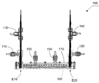
本実施形態のプラズマ発生装置について説明する。本実施形態のプラズマ発生装置100は、大気圧下でプラズマを発生させる大気圧プラズマ発生装置である。図1に示すように、プラズマ発生装置100は、第1の電極部E10と、第2の電極部E20と、第1の電極部ガス供給部110と、第2の電極部ガス供給部120と、第1の電極部ガス排出部130と、第2の電極部ガス排出部140と、主ガス供給部150、160と、筐体部170と、を有している。
1. Configuration of Plasma Generator The plasma generator of this embodiment will be described. The
第1の電極部E10と、第2の電極部E20とは、これらの間に放電させるためのものである。第1の電極部E10と、第2の電極部E20とは、それぞれ、電極を有している。詳しくは、後述する。 The first electrode portion E10 and the second electrode portion E20 are for discharging between them. The first electrode part E10 and the second electrode part E20 each have an electrode. Details will be described later.
第1の電極部ガス供給部110は、第1の電極部E10にガスを供給するためのガス供給部である。第1の電極部ガス排出部130は、第1の電極部E10からガスを排出するためのガス排出部である。第2の電極部ガス供給部120は、第2の電極部E20にガスを供給するためのガス供給部である。第2の電極部ガス排出部140は、第2の電極部E20からガスを排出するためのガス排出部である。
The first electrode part
第1の電極部ガス供給部110と、第2の電極部ガス供給部120と、第1の電極部ガス排出部130と、第2の電極部ガス排出部140とは、具体的には、弁である。そして、弁の開放時には、それぞれ、ガスの供給もしくは排出を行うことができるようになっている。
Specifically, the first electrode unit
筐体部170の内部には、プラズマを発生させるための空間部180がある。主ガス供給部150、160は、筐体部170の空間部180にプラズマを発生させるための原料ガスを供給するためのものである。例えば、酸素や、水素、フッ素、窒素が挙げられる。もちろん、これ以外のガスであってもよい。また、Ar等の希ガスを所定量混合した混合ガスであってもよい。この原料ガスにより、発生するラジカルが決まる。そのため、空間部180の一部は、プラズマを発生させるプラズマ発生部である。
Inside the
2.電極部の構成
図2に、第1の電極部E10および第2の電極部E20の概略構成を示す。第1の電極部E10および第2の電極部E20の構成は、ほぼ同様である。そのため、主に第1の電極部E10について説明する。なお、図2では、第2の電極部E20の構成を示す符合を括弧内に示す。
2. Configuration of Electrode Unit FIG. 2 shows a schematic configuration of the first electrode unit E10 and the second electrode unit E20. The configurations of the first electrode portion E10 and the second electrode portion E20 are substantially the same. Therefore, the first electrode part E10 will be mainly described. In FIG. 2, the reference numerals indicating the configuration of the second electrode portion E20 are shown in parentheses.
第1の電極部E10は、第1の電極E11を有している。第2の電極部E20は、第2の電極E21を有している。プラズマ発生装置100は、図示しない高電圧電源を有している。この高電圧電源は、第1の電極E11と第2の電極E21との間に電圧を印加する電圧印加部である。高電圧電源として、例えば、60Hz交流または50Hz交流を昇圧した高電圧電源や高周波高電圧電源を用いることができる。
The first electrode portion E10 has a first electrode E11. The second electrode part E20 has a second electrode E21. The
図2に示すように、第1の電極部E10は、第1の電極E11の他に、被覆絶縁部材20と、内側絶縁部材30と、外側絶縁部材40と、ガス供給路60と、ガス排出路70と、第1の予備室P11と、を有している。第1の電極E11の先端部分には、ホローH11が形成されている。ホローH11は、微細な凹部を繰り返し形成されたマイクロホローである。
As shown in FIG. 2, in addition to the first electrode E11, the first electrode portion E10 includes a
また、第2の電極部E20は、第1の電極E11の他に、被覆絶縁部材20と、内側絶縁部材30と、外側絶縁部材40と、ガス供給路60と、ガス排出路70と、第2の予備室P21と、を有している。第2の電極E21の先端部分には、ホローH21が形成されている。ホローH21は、ホローH11と同様である。
In addition to the first electrode E11, the second electrode portion E20 includes the
第1の電極E11の形状は、ホローH11の箇所を除いて円柱形状である。もちろん、これ以外の形状であってもよい。第1の電極E11の材質は、放電により、変形等(変形・溶解・蒸発を含む)を起こさない金属であればよい。例えば、モリブデンやタングステン、チタン、ステンレス鋼が挙げられる。これらのうち、銅であると好ましい。より好ましくは、無酸素銅である。第2の電極E21についても同様である。 The shape of the first electrode E11 is a cylindrical shape except for the location of the hollow H11. Of course, other shapes may be used. The material of the first electrode E11 may be a metal that does not undergo deformation or the like (including deformation, dissolution, or evaporation) by discharge. For example, molybdenum, tungsten, titanium, and stainless steel can be used. Of these, copper is preferred. More preferably, it is oxygen-free copper. The same applies to the second electrode E21.
被覆絶縁部材20は、第1の電極E11または第2の電極E21を被覆するための絶縁部材である。ただし、被覆絶縁部材20は、第1の電極E11または第2の電極E21の先端部分を覆っていない。したがって、ホローH11もしくはホローH21は、被覆絶縁部材20から露出している。被覆絶縁部材20の形状は、円筒形状である。その円筒内面に、第1の電極E11が収容されている。被覆絶縁部材20の材質は、例えば、セラミックである。もちろん、他のものであってもよい。
The covering insulating
内側絶縁部材30は、円筒形状の絶縁部材である。内側絶縁部材30は、その円筒内部に、第1の電極E11および被覆絶縁部材20を収容している。内側絶縁部材30には、複数の貫通孔31が形成されている。貫通孔31は、内側絶縁部材30の円筒面にわたって形成されている。つまり、貫通孔31は、ガス供給路60とガス排出路70とを連通する連通部である。そして、貫通孔31があることにより、第1の電極部E10の予備室P11と第2の電極部E20の予備室P21とは、連通している。このように、内側絶縁部材30は、連通部を備える絶縁部材である。図2では、これらの貫通孔31は、2列形成されている。また、これらの貫通孔31は、1列であってもよいし、3列以上であってもよい。貫通孔31の径は、φ1mm程度である。もちろん、これは例示であり、これ以外の値であってもよい。
The inner insulating
外側絶縁部材40は、円筒形状の絶縁部材である。外側絶縁部材40は、その円筒内部に、内側絶縁部材30を収容している。つまり、外側絶縁部材40は、内側絶縁部材30の外側に位置している。
The outer insulating
絶縁部材50は、外側絶縁部材40の一部を覆う筐体170の一部である。絶縁部材50には、貫通孔51が設けられている。貫通孔51は、プラズマ発生部P1と連通している。なお、内側絶縁部材30および外側絶縁部材40および絶縁部材50の材質は、例えば、セラミックである。もちろん、他のものであってもよい。
The insulating
第1の予備室P11および第2の予備室P21は、それぞれ、第1の電極E11および第2の電極E21を囲う空間である。第1の予備室P11および第2の予備室P21は、予備プラズマを発生させるためのものである。 The first preliminary chamber P11 and the second preliminary chamber P21 are spaces surrounding the first electrode E11 and the second electrode E21, respectively. The first preliminary chamber P11 and the second preliminary chamber P21 are for generating preliminary plasma.
2−2.ガス供給路およびガス排出路
ガス供給路60は、内側絶縁部材30と、外側絶縁部材40との間に形成されている。ガス供給路60は、第1の電極E11の予備室P11の中に向けてガスを供給するためのものである。そのため、ガス供給路60は、第1の予備室P11もしくは第2の予備室P21と貫通孔31を介して連通している。
2-2. Gas supply path and gas discharge path The
ガス排出路70は、内側絶縁部材30と、被覆絶縁部材20との間に形成されている。ガス排出路70は、第1の電極E11の予備室P11からガスを排出するためのものである。そのため、ガス排出路70は、第1の予備室P11もしくは第2の予備室P21と連通している。
The gas discharge path 70 is formed between the inner insulating
内側絶縁部材30の貫通孔31は、ガス供給路60と、ガス排出路70とを連通するものである。したがって、ガス供給路60から送り出されてきたガスは、貫通孔31を通って、ガス排出路70に向うようになっている。また、第2の電極部E20の側についても同様である。
The through
貫通孔51は、プラズマ発生部P1およびガス供給路60と連通している。また、ガス供給路60は、貫通孔31を介して予備室P11およびガス排出路70と連通している。また、貫通孔31は、プラズマ発生部P1と連通している。したがって、プラズマ発生部P1は、第1の電極部E10の予備室P11および第2の電極部E20の予備室P21と連通している。
The through
3.使用時におけるプラズマ発生装置
3−1.放電開始前
図3に示すように、プラズマ発生装置100の使用時には、主ガス供給部150、160から原料ガスが供給される。この原料ガスは、ラジカル源となるガスである。原料ガスとして例えば、酸素、水素、フッ素、窒素が挙げられる。もちろん、これ以外のガスを用いもよい。また、これらのガスにArガス等の希ガスを混合した混合気体を供給してもよい。
3. 3. Plasma generator in use 3-1. Before the start of discharge As shown in FIG. 3, when the
そして、第1の電極部ガス供給部110および第2の電極部ガス供給部120から、Arガスを第1の電極E11および第2の電極E21のそれぞれの箇所に供給する。つまり、Arガスは、ガス供給路60を矢印D1の向きに流れる。そのため、ガス供給路60を流れるArガスの一部は、貫通孔31を通って、予備室P11もしくは予備室P21に入る。そして、Arガスは、図3の矢印D2の向きに進む。
Then, Ar gas is supplied from the first electrode part
一方、ガス供給路60を流れるArガスの残部は、貫通孔51を通って、矢印D3の向きに流れる。つまり、プラズマ発生部P1に向って流れる。ただし、その流量は少ない。プラズマ発生部P1では、主ガス供給部150、160から原料ガスが流入するとともに、貫通孔51からArガスが流入する。なお、プラズマ発生部P1における気圧Xは、大気圧程度(0.8気圧≦X≦1.2気圧)である。
On the other hand, the remaining Ar gas flowing through the
このように、ガス供給路60を流れるArガスは、予備室P11、P21またはプラズマ発生部P1に流れる。そして、予備室P11、P21では、Arガスはガス排出路70に流れる。
Thus, the Ar gas flowing through the
3−2.放電開始後
そして、第1の電極E11と第2の電極E21との間に電圧を印加する。これにより、図4に示すように、第1の電極E11のホローH11の周辺と、第2の電極E21のホローH21の周辺とに、予備プラズマPPが発生する。そして、予備プラズマPPは、
第1の電極E11と第2の電極E21との間の空間部180側に拡大する。そして、貫通孔51を通ってさらに広がる。
3-2. After the start of discharge, a voltage is applied between the first electrode E11 and the second electrode E21. Thereby, as shown in FIG. 4, preliminary plasma PP is generated around the hollow H11 of the first electrode E11 and around the hollow H21 of the second electrode E21. And the preliminary plasma PP is
It expands to the
やがて、予備プラズマPPは、空間部180にまで達する。これにより、第1の予備室P11から第2の予備室P21までの間にかけてプラズマが発生する。そして、プラズマ化した原料ガスの一部は、筐体170の内壁に衝突して中性化してラジカルとなる。そのラジカルの一部は、筐体部170に設けられた多数の貫通孔R1から排出される。このラジカルを、基板の清浄化等に利用する。
Eventually, the preliminary plasma PP reaches the
3−3.金属微粒子の排出効果
第1の予備室P11では、放電により第1の電極E11から生じる金属微粒子が飛散している。ここで、貫通孔31から入ってきたガスは、前述したように、ガス排出路70に向けて流れている。つまり、第1の予備室P11では、ガス排出路70に向けて流れるArガスの流れが既にできている状態にある。そのため、金属微粒子は、ガス排出路70を通って第1の電極部ガス排出部130から排出される。つまり、第1の電極E11の周囲の絶縁部材に付着するおそれもほとんどなく、第1の電極E11に再度付着するおそれもほとんどない。また、プラズマ発生部P1に飛散するおそれもほとんどない。
3-3. Discharge effect of metal fine particles In the first preliminary chamber P11, metal fine particles generated from the first electrode E11 are scattered by discharge. Here, the gas that has entered from the through
また、第1の予備室P11の内部には、Arガスが流れている。そのため、第1の電極E11に酸化被膜が形成されるおそれもない。もちろん、Arガスの代わりに、その他の希ガスを用いてもよい。これらのことは、第2の電極部E20においても同様である。 In addition, Ar gas flows in the first preliminary chamber P11. Therefore, there is no possibility that an oxide film is formed on the first electrode E11. Of course, other rare gases may be used instead of Ar gas. The same applies to the second electrode portion E20.
3−4.従来との比較
従来のプラズマ発生装置には、本実施形態のようなガス供給路60およびガス排出路70が設けられていない。したがって、電極周辺にスパッタリング粒子等の微粒子が飛散している状態にある。このような微粒子は、電極周辺の絶縁部材等に付着することがある。これにより、放電が不安定となるおそれがある。放電が不安定となれば、発生させるプラズマを制御することは困難となる。
3-4. Comparison with the Conventional A conventional plasma generator is not provided with the
また、微粒子は、プラズマ発生部P1のほうに飛散するおそれもある。その場合には、微粒子が処理対象物に向けて飛散し、処理対象物表面の表面に付着するおそれがある。これは、製品となる処理対象物の品質を損なう原因となる。 Further, the fine particles may be scattered toward the plasma generation part P1. In that case, there is a possibility that the fine particles are scattered toward the object to be processed and adhere to the surface of the object to be processed. This becomes a cause of impairing the quality of the processing object as a product.
4.変形例
4−1.貫通孔の大きさ
本実施形態では、複数の貫通孔31を、内側絶縁部材30の周囲で同じ形状および同じ大きさとした。しかし、貫通孔31を放電側(プラズマ領域P1側)に、径の大きい貫通孔31を配置することとしてもよい。
4). Modified example 4-1. In the present embodiment, the plurality of through
4−2.貫通孔の形状
また、貫通孔31の形状を円形ではなく、スリット形状としてもよい。また、その他の多角形としてもよい。このように、貫通孔31の形状は問わない。貫通孔31の形状によらず、同様の効果を奏するからである。
4-2. The shape of the through hole The shape of the through
4−3.Arガスの流れる方向
本実施形態では、ガス供給路60を外側に設けるとともに、ガス排出路70をガス供給路60の内側に設けた。しかし、これらの位置関係を逆にしてもよい。つまり、Arガスを内側の通路から流すとともに、外側の通路から排出するのである。
4-3. Direction of Ar Gas Flow In this embodiment, the
5.まとめ
以上詳細に説明したように、本実施形態に係るプラズマ発生装置100では、第1の電極E11および第2の電極E21の箇所周辺にガスを供給するガス供給路60と、ガスを排出するガス排出路70とが設けられている。そのため、プラズマ発生装置100の使用時には、第1の電極E11および第2の電極E21から発生する微粒子が、排出ガスとともに排出される。したがって、第1の電極E11および第2の電極E21の劣化を防止するプラズマ発生装置100が実現されている。
5. Summary As described in detail above, in the
なお、本実施形態は単なる例示にすぎない。したがって当然に、その要旨を逸脱しない範囲内で種々の改良、変形が可能である。例えば、電極対の形状は、実施形態で説明したものに限らない。つまり、ホローが形成されているものに限らない。また、電極および絶縁体の材質については、記載したものに限らない。電極間距離が比較的長い(5cm程度)大気圧プラズマ発生装置について説明した。しかし、電極間距離によらず、本発明を適用できる。また、ガス供給路60およびガス排出路70の配置は、少なくとも一方の電極部であっても効果を奏する。
This embodiment is merely an example. Therefore, naturally, various improvements and modifications can be made without departing from the scope of the invention. For example, the shape of the electrode pair is not limited to that described in the embodiment. That is, it is not limited to the one in which the hollow is formed. Further, the materials of the electrode and the insulator are not limited to those described. An atmospheric pressure plasma generator having a relatively long distance between electrodes (about 5 cm) has been described. However, the present invention can be applied regardless of the distance between the electrodes. Further, the arrangement of the
100…プラズマ発生装置
110…第1の電極部ガス供給部
120…第2の電極部ガス供給部
130…第1の電極部ガス排出部
140…第2の電極部ガス排出部
150、160…主ガス供給部
170…筐体
180…空間部
20…被覆絶縁部材
30…内側絶縁部材
31…貫通孔
40…外側絶縁部材
50…絶縁部材
51…貫通孔
60…ガス供給路
70…ガス排出路
E10…第1の電極部
E11…第1の電極
E20…第2の電極部
E21…第2の電極
H11、H21…ホロー
P11…第1の予備室
P21…第2の予備室
P1…プラズマ発生部
R1…貫通孔
DESCRIPTION OF
Claims (6)
第2の電極を有する第2の電極部と、
を有する大気圧プラズマ発生装置において、
前記第1の電極部と前記第2の電極部との少なくとも一方は、
前記第1の電極もしくは前記第2の電極を囲う予備室と、
前記予備室にガスを供給するガス供給路と、
前記予備室からガスを排出するガス排出路と、
前記第1の電極もしくは前記第2の電極および前記予備室を備える絶縁部材と、
を有し、
前記絶縁部材は、
前記ガス供給路と前記ガス排出路とを連通する連通部を有し、
前記第1の電極および前記第2の電極は、
先端部分に凹部の形成されたマイクロホロー電極であること
を特徴とする大気圧プラズマ発生装置。 A first electrode portion having a first electrode;
A second electrode portion having a second electrode;
In an atmospheric pressure plasma generator having
At least one of the first electrode portion and the second electrode portion is:
A spare chamber surrounding the first electrode or the second electrode;
A gas supply path for supplying gas to the preliminary chamber;
A gas discharge path for discharging gas from the preliminary chamber;
An insulating member comprising the first electrode or the second electrode and the preliminary chamber;
I have a,
The insulating member is
Having a communication part for communicating the gas supply path and the gas discharge path;
The first electrode and the second electrode are:
An atmospheric pressure plasma generator characterized in that it is a micro-hollow electrode having a recess formed at the tip.
第2の電極を有する第2の電極部と、
を有する大気圧プラズマ発生装置において、
前記第1の電極部と前記第2の電極部との少なくとも一方は、
前記第1の電極もしくは前記第2の電極を囲う予備室と、
前記予備室にガスを供給するガス供給路と、
前記予備室からガスを排出するガス排出路と、
前記ガス供給路と前記ガス排出路とを連通する連通部と、
前記第1の電極もしくは前記第2の電極を先端部分を除いて被覆する被覆絶縁部材と、
前記被覆絶縁部材の外側に、前記連通部を備える絶縁部材と、
を有し、
前記絶縁部材は、前記予備室を備えており、
前記連通部を備える絶縁部材と前記被覆絶縁部材との間に、前記ガス排出路が形成されていること
を特徴とする大気圧プラズマ発生装置。 A first electrode portion having a first electrode;
A second electrode portion having a second electrode;
In an atmospheric pressure plasma generator having
At least one of the first electrode portion and the second electrode portion is:
A spare chamber surrounding the first electrode or the second electrode;
A gas supply path for supplying gas to the preliminary chamber;
A gas discharge path for discharging gas from the preliminary chamber;
A communication part for communicating the gas supply path and the gas discharge path;
A covering insulating member that covers the first electrode or the second electrode except for a tip portion; and
An insulating member provided with the communication part on the outside of the covering insulating member;
Have
The insulating member includes the preliminary chamber,
The atmospheric pressure plasma generating apparatus, wherein the gas discharge path is formed between an insulating member having the communication portion and the covering insulating member.
前記連通部は、
前記第1の電極部の予備室と前記第2の電極部の予備室とを連通するものであること
を特徴とする大気圧プラズマ発生装置。 In the atmospheric pressure plasma generator according to claim 1 or 2,
The communication part is
An atmospheric pressure plasma generator characterized in that the preliminary chamber of the first electrode section and the preliminary chamber of the second electrode section communicate with each other.
前記連通部は、
前記絶縁部材に形成された複数の貫通孔であること
を特徴とする大気圧プラズマ発生装置。 In the atmospheric pressure plasma generator according to any one of claims 1 to 3 ,
The communication part is
An atmospheric pressure plasma generator comprising a plurality of through holes formed in the insulating member.
前記連通部を備える前記絶縁部材は、
円筒形状をしており、
前記貫通孔は、
前記円筒形状の円筒面にわたって形成されていること
を特徴とする大気圧プラズマ発生装置。 In the atmospheric pressure plasma generator according to claim 4 ,
It said insulating member having the communicating portion,
It has a cylindrical shape,
The through hole is
The atmospheric pressure plasma generator is formed over the cylindrical surface of the cylindrical shape.
第2の電極を有する第2の電極部と、
を有する大気圧プラズマ発生装置において、
前記第1の電極部と前記第2の電極部との少なくとも一方は、
前記第1の電極もしくは前記第2の電極を囲う予備室と、
前記予備室にガスを供給するガス供給路と、
前記予備室からガスを排出するガス排出路と、
前記ガス供給路と前記ガス排出路とを連通する連通部と、
を有し、
前記連通部は、
絶縁部材に形成された複数の貫通孔であり、
前記連通部を備える絶縁部材は、
前記予備室を備えるとともに円筒形状をしており、
前記貫通孔は、
前記円筒形状の円筒面にわたって形成されていること
を特徴とする大気圧プラズマ発生装置。 A first electrode portion having a first electrode;
A second electrode portion having a second electrode;
In an atmospheric pressure plasma generator having
At least one of the first electrode portion and the second electrode portion is:
A spare chamber surrounding the first electrode or the second electrode;
A gas supply path for supplying gas to the preliminary chamber;
A gas discharge path for discharging gas from the preliminary chamber;
A communication part for communicating the gas supply path and the gas discharge path;
Have
The communication part is
A plurality of through holes formed in the insulating member;
The insulating member provided with the communication part is
It has a cylindrical shape with the preliminary chamber ,
The through hole is
The atmospheric pressure plasma generator is formed over the cylindrical surface of the cylindrical shape.
Priority Applications (1)
| Application Number | Priority Date | Filing Date | Title |
|---|---|---|---|
| JP2012083362A JP5961899B2 (en) | 2012-03-31 | 2012-03-31 | Atmospheric pressure plasma generator |
Applications Claiming Priority (1)
| Application Number | Priority Date | Filing Date | Title |
|---|---|---|---|
| JP2012083362A JP5961899B2 (en) | 2012-03-31 | 2012-03-31 | Atmospheric pressure plasma generator |
Publications (2)
| Publication Number | Publication Date |
|---|---|
| JP2013214377A JP2013214377A (en) | 2013-10-17 |
| JP5961899B2 true JP5961899B2 (en) | 2016-08-03 |
Family
ID=49587592
Family Applications (1)
| Application Number | Title | Priority Date | Filing Date |
|---|---|---|---|
| JP2012083362A Active JP5961899B2 (en) | 2012-03-31 | 2012-03-31 | Atmospheric pressure plasma generator |
Country Status (1)
| Country | Link |
|---|---|
| JP (1) | JP5961899B2 (en) |
Families Citing this family (3)
| Publication number | Priority date | Publication date | Assignee | Title |
|---|---|---|---|---|
| JP6591735B2 (en) * | 2014-08-05 | 2019-10-16 | 株式会社Fuji | Plasma generator |
| WO2018096606A1 (en) | 2016-11-24 | 2018-05-31 | 株式会社Fuji | Plasma generating apparatus |
| WO2021159225A1 (en) * | 2020-02-10 | 2021-08-19 | Yangtze Memory Technologies Co., Ltd. | Metal contamination test apparatus and method |
Family Cites Families (1)
| Publication number | Priority date | Publication date | Assignee | Title |
|---|---|---|---|---|
| JP2005243905A (en) * | 2004-02-26 | 2005-09-08 | Kansai Tlo Kk | Plasma treatment method and apparatus thereof |
-
2012
- 2012-03-31 JP JP2012083362A patent/JP5961899B2/en active Active
Also Published As
| Publication number | Publication date |
|---|---|
| JP2013214377A (en) | 2013-10-17 |
Similar Documents
| Publication | Publication Date | Title |
|---|---|---|
| JP5248370B2 (en) | Shower head and plasma processing apparatus | |
| CN112166650B (en) | Active gas generating device | |
| JP2009503781A (en) | Injection type plasma processing apparatus and method | |
| US20080245478A1 (en) | Surface treatment apparatus | |
| JP5961899B2 (en) | Atmospheric pressure plasma generator | |
| KR102545951B1 (en) | active gas generator | |
| US10577261B2 (en) | Water treatment apparatus and water treatment method | |
| KR20070012933A (en) | Injection type plasma treatment apparatus | |
| US20100258247A1 (en) | Atmospheric pressure plasma generator | |
| JP2010272355A (en) | Apparatus for generating active particle | |
| WO2006075570A1 (en) | Plasma generating apparatus | |
| US20190189405A1 (en) | Two-Phased Atmospheric Plasma Generator | |
| US20220020567A1 (en) | Plasma processing apparatus and plasma processing method | |
| JP2007258097A (en) | Plasma processing apparatus | |
| JP2017010792A (en) | Plasma generator | |
| JP7328500B2 (en) | Atmospheric plasma processing equipment | |
| JP4784977B2 (en) | Radical generator | |
| JP2010177137A (en) | High-density plasma source, and forming method of high density plasma | |
| JP2013145719A (en) | Plasma processing apparatus and plasma processing method | |
| WO2022070945A1 (en) | Plasma processing device | |
| JP2005353636A (en) | Plasma processing apparatus | |
| JP2003338251A (en) | Ion source | |
| KR20100120590A (en) | Treatment device using plasma | |
| JP6801483B2 (en) | Plasma generator and plasma generation method | |
| JP6863608B2 (en) | Plasma source and plasma processing equipment |
Legal Events
| Date | Code | Title | Description |
|---|---|---|---|
| A621 | Written request for application examination |
Free format text: JAPANESE INTERMEDIATE CODE: A621 Effective date: 20150327 |
|
| A521 | Request for written amendment filed |
Free format text: JAPANESE INTERMEDIATE CODE: A821 Effective date: 20150327 |
|
| A521 | Request for written amendment filed |
Free format text: JAPANESE INTERMEDIATE CODE: A523 Effective date: 20150525 |
|
| A131 | Notification of reasons for refusal |
Free format text: JAPANESE INTERMEDIATE CODE: A131 Effective date: 20151222 |
|
| A521 | Request for written amendment filed |
Free format text: JAPANESE INTERMEDIATE CODE: A523 Effective date: 20160218 |
|
| TRDD | Decision of grant or rejection written | ||
| A01 | Written decision to grant a patent or to grant a registration (utility model) |
Free format text: JAPANESE INTERMEDIATE CODE: A01 Effective date: 20160517 |
|
| A61 | First payment of annual fees (during grant procedure) |
Free format text: JAPANESE INTERMEDIATE CODE: A61 Effective date: 20160610 |
|
| R150 | Certificate of patent or registration of utility model |
Ref document number: 5961899 Country of ref document: JP Free format text: JAPANESE INTERMEDIATE CODE: R150 |
|
| S533 | Written request for registration of change of name |
Free format text: JAPANESE INTERMEDIATE CODE: R313533 |
|
| R350 | Written notification of registration of transfer |
Free format text: JAPANESE INTERMEDIATE CODE: R350 |
|
| R250 | Receipt of annual fees |
Free format text: JAPANESE INTERMEDIATE CODE: R250 |
|
| R250 | Receipt of annual fees |
Free format text: JAPANESE INTERMEDIATE CODE: R250 |
|
| R250 | Receipt of annual fees |
Free format text: JAPANESE INTERMEDIATE CODE: R250 |