JP5961260B2 - Multi-vane throttle valve - Google Patents
Multi-vane throttle valve Download PDFInfo
- Publication number
- JP5961260B2 JP5961260B2 JP2014521720A JP2014521720A JP5961260B2 JP 5961260 B2 JP5961260 B2 JP 5961260B2 JP 2014521720 A JP2014521720 A JP 2014521720A JP 2014521720 A JP2014521720 A JP 2014521720A JP 5961260 B2 JP5961260 B2 JP 5961260B2
- Authority
- JP
- Japan
- Prior art keywords
- vane
- rotary
- throttle valve
- chamber
- coolant
- Prior art date
- Legal status (The legal status is an assumption and is not a legal conclusion. Google has not performed a legal analysis and makes no representation as to the accuracy of the status listed.)
- Active
Links
Images


Classifications
-
- F—MECHANICAL ENGINEERING; LIGHTING; HEATING; WEAPONS; BLASTING
- F16—ENGINEERING ELEMENTS AND UNITS; GENERAL MEASURES FOR PRODUCING AND MAINTAINING EFFECTIVE FUNCTIONING OF MACHINES OR INSTALLATIONS; THERMAL INSULATION IN GENERAL
- F16K—VALVES; TAPS; COCKS; ACTUATING-FLOATS; DEVICES FOR VENTING OR AERATING
- F16K51/00—Other details not peculiar to particular types of valves or cut-off apparatus
- F16K51/02—Other details not peculiar to particular types of valves or cut-off apparatus specially adapted for high-vacuum installations
-
- F—MECHANICAL ENGINEERING; LIGHTING; HEATING; WEAPONS; BLASTING
- F16—ENGINEERING ELEMENTS AND UNITS; GENERAL MEASURES FOR PRODUCING AND MAINTAINING EFFECTIVE FUNCTIONING OF MACHINES OR INSTALLATIONS; THERMAL INSULATION IN GENERAL
- F16K—VALVES; TAPS; COCKS; ACTUATING-FLOATS; DEVICES FOR VENTING OR AERATING
- F16K1/00—Lift valves or globe valves, i.e. cut-off apparatus with closure members having at least a component of their opening and closing motion perpendicular to the closing faces
- F16K1/16—Lift valves or globe valves, i.e. cut-off apparatus with closure members having at least a component of their opening and closing motion perpendicular to the closing faces with pivoted closure-members
- F16K1/18—Lift valves or globe valves, i.e. cut-off apparatus with closure members having at least a component of their opening and closing motion perpendicular to the closing faces with pivoted closure-members with pivoted discs or flaps
- F16K1/22—Lift valves or globe valves, i.e. cut-off apparatus with closure members having at least a component of their opening and closing motion perpendicular to the closing faces with pivoted closure-members with pivoted discs or flaps with axis of rotation crossing the valve member, e.g. butterfly valves
- F16K1/222—Shaping of the valve member
-
- F—MECHANICAL ENGINEERING; LIGHTING; HEATING; WEAPONS; BLASTING
- F16—ENGINEERING ELEMENTS AND UNITS; GENERAL MEASURES FOR PRODUCING AND MAINTAINING EFFECTIVE FUNCTIONING OF MACHINES OR INSTALLATIONS; THERMAL INSULATION IN GENERAL
- F16K—VALVES; TAPS; COCKS; ACTUATING-FLOATS; DEVICES FOR VENTING OR AERATING
- F16K1/00—Lift valves or globe valves, i.e. cut-off apparatus with closure members having at least a component of their opening and closing motion perpendicular to the closing faces
- F16K1/16—Lift valves or globe valves, i.e. cut-off apparatus with closure members having at least a component of their opening and closing motion perpendicular to the closing faces with pivoted closure-members
- F16K1/18—Lift valves or globe valves, i.e. cut-off apparatus with closure members having at least a component of their opening and closing motion perpendicular to the closing faces with pivoted closure-members with pivoted discs or flaps
- F16K1/22—Lift valves or globe valves, i.e. cut-off apparatus with closure members having at least a component of their opening and closing motion perpendicular to the closing faces with pivoted closure-members with pivoted discs or flaps with axis of rotation crossing the valve member, e.g. butterfly valves
- F16K1/223—Lift valves or globe valves, i.e. cut-off apparatus with closure members having at least a component of their opening and closing motion perpendicular to the closing faces with pivoted closure-members with pivoted discs or flaps with axis of rotation crossing the valve member, e.g. butterfly valves with a plurality of valve members
-
- F—MECHANICAL ENGINEERING; LIGHTING; HEATING; WEAPONS; BLASTING
- F16—ENGINEERING ELEMENTS AND UNITS; GENERAL MEASURES FOR PRODUCING AND MAINTAINING EFFECTIVE FUNCTIONING OF MACHINES OR INSTALLATIONS; THERMAL INSULATION IN GENERAL
- F16K—VALVES; TAPS; COCKS; ACTUATING-FLOATS; DEVICES FOR VENTING OR AERATING
- F16K49/00—Means in or on valves for heating or cooling
- F16K49/005—Circulation means for a separate heat transfer fluid
- F16K49/007—Circulation means for a separate heat transfer fluid located within the obturating element
-
- Y—GENERAL TAGGING OF NEW TECHNOLOGICAL DEVELOPMENTS; GENERAL TAGGING OF CROSS-SECTIONAL TECHNOLOGIES SPANNING OVER SEVERAL SECTIONS OF THE IPC; TECHNICAL SUBJECTS COVERED BY FORMER USPC CROSS-REFERENCE ART COLLECTIONS [XRACs] AND DIGESTS
- Y10—TECHNICAL SUBJECTS COVERED BY FORMER USPC
- Y10T—TECHNICAL SUBJECTS COVERED BY FORMER US CLASSIFICATION
- Y10T137/00—Fluid handling
- Y10T137/0318—Processes
-
- Y—GENERAL TAGGING OF NEW TECHNOLOGICAL DEVELOPMENTS; GENERAL TAGGING OF CROSS-SECTIONAL TECHNOLOGIES SPANNING OVER SEVERAL SECTIONS OF THE IPC; TECHNICAL SUBJECTS COVERED BY FORMER USPC CROSS-REFERENCE ART COLLECTIONS [XRACs] AND DIGESTS
- Y10—TECHNICAL SUBJECTS COVERED BY FORMER USPC
- Y10T—TECHNICAL SUBJECTS COVERED BY FORMER US CLASSIFICATION
- Y10T137/00—Fluid handling
- Y10T137/6416—With heating or cooling of the system
- Y10T137/6579—Circulating fluid in heat exchange relationship
-
- Y—GENERAL TAGGING OF NEW TECHNOLOGICAL DEVELOPMENTS; GENERAL TAGGING OF CROSS-SECTIONAL TECHNOLOGIES SPANNING OVER SEVERAL SECTIONS OF THE IPC; TECHNICAL SUBJECTS COVERED BY FORMER USPC CROSS-REFERENCE ART COLLECTIONS [XRACs] AND DIGESTS
- Y10—TECHNICAL SUBJECTS COVERED BY FORMER USPC
- Y10T—TECHNICAL SUBJECTS COVERED BY FORMER US CLASSIFICATION
- Y10T137/00—Fluid handling
- Y10T137/8593—Systems
- Y10T137/86928—Sequentially progressive opening or closing of plural valves
- Y10T137/86936—Pressure equalizing or auxiliary shunt flow
-
- Y—GENERAL TAGGING OF NEW TECHNOLOGICAL DEVELOPMENTS; GENERAL TAGGING OF CROSS-SECTIONAL TECHNOLOGIES SPANNING OVER SEVERAL SECTIONS OF THE IPC; TECHNICAL SUBJECTS COVERED BY FORMER USPC CROSS-REFERENCE ART COLLECTIONS [XRACs] AND DIGESTS
- Y10—TECHNICAL SUBJECTS COVERED BY FORMER USPC
- Y10T—TECHNICAL SUBJECTS COVERED BY FORMER US CLASSIFICATION
- Y10T137/00—Fluid handling
- Y10T137/8593—Systems
- Y10T137/87265—Dividing into parallel flow paths with recombining
- Y10T137/8741—With common operator
- Y10T137/87442—Rotary valve
- Y10T137/87467—Axes of rotation parallel
- Y10T137/87475—Adjacent plate valves always parallel
Description
[発明の背景]
1.発明の分野
本発明は、一般に、処理システム用バルブに関する。特に、本発明は、真空システム用スロットルバルブに関する。
2.従来技術の説明
様々なバルブが真空処理システムで用いられるために考え出されている。バルブのタイプとしては、ゲートバルブ、バタフライ弁、マルチベーン型バルブなどがあげられる。ゲートバルブの中には、開位置および閉位置が設計され、そのバルブを介してガス状流体の全開フローまたは全閉フローのいずれかを許容するものがある。バタフライ弁の設計は比較的容易であるが、線形コンダクタンス応答を達成する能力に限界がある。マルチベーン型バルブは、バタフライ弁よりもより高精度な制御を提供する。
[Background of the invention]
1. The present invention generally relates to valves for processing systems. In particular, the present invention relates to a throttle valve for a vacuum system.
2. 2. Description of the Prior Art Various valves have been devised for use in vacuum processing systems. Examples of the valve type include a gate valve, a butterfly valve, and a multi-vane valve. Some gate valves are designed to have an open position and a closed position through which either a fully open flow or a fully closed flow of gaseous fluid is allowed. The design of a butterfly valve is relatively easy but has a limited ability to achieve a linear conductance response. Multi-vane valves provide more precise control than butterfly valves.
マルチベーン型バルブの一例が米国特許番号6,293,306(ブレネス、2001)に記載される。ブレネスには、直立で概ね長方形のバルブ筺体を有するスロットルゲートバルブが記載されている。バルブ筺体の中には、バルブ筺体の下部に形成された貫通穴を閉じるための、直線的に移動可能なゲートバルブが配置される。空気圧式アクチュエータアッセンブリによって、開位置および閉位置の間でゲートバルブが移動する。スロットルバルブアッセンブリコンパートメントは、バルブ筺体の下側を形成し、貫通穴を画定し、貫通穴内で回転可能に配置された一組のスロットルベーンを有する。ドライブアクチュエータは、ベーンを回転するために設けられ、ドライブアクチュエータコンパートメントと、スロットルベーンの位置を制御するモータとを有する。ドライブアクチュエータは、そのドライブアクチュエータが筺体の内側に延在する地点でベローズシールドによって密封される。 An example of a multi-vane valve is described in US Pat. No. 6,293,306 (Brenesse, 2001). Brennes describes a throttle gate valve having an upright, generally rectangular valve housing. A linearly movable gate valve for closing a through hole formed in the lower part of the valve housing is disposed in the valve housing. A pneumatic actuator assembly moves the gate valve between an open position and a closed position. The throttle valve assembly compartment forms a bottom side of the valve housing, defines a through hole, and has a set of throttle vanes that are rotatably disposed within the through hole. The drive actuator is provided for rotating the vane and has a drive actuator compartment and a motor for controlling the position of the throttle vane. The drive actuator is sealed by a bellows shield at the point where the drive actuator extends inside the housing.
マルチベーン型バルブの他のタイプとしては、メイバック,インクが商標「Vari−Q」を付して販売するスロットルバルブがある。メイバックのスロットルバルブは、低摩擦ケーブル駆動システムによって相互接続する複数の二重反転する三角形(つまりパイ形状)のベーンを収容する環状のバルブチャンバを有する。 Another type of multi-vane valve is a throttle valve sold by Maybuck, Inc. under the trademark “Vari-Q”. The Mayback throttle valve has an annular valve chamber that houses a plurality of counter-rotating triangular (ie, pie-shaped) vanes that are interconnected by a low friction cable drive system.
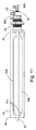
マルチベーン型バルブのさらに他のタイプとしては、部品番号0627−0624−0として、フェローテック社(米国)が商標「Temescal」を付して販売する固定ベーンバルブがある。このマルチベーン型バルブは、全てのベーンが30度から45度の範囲で固定されており、低温ポンプと流体連結するので、本当の意味ではバルブではない。各ベーンは、各ベーンに対して直角であるステンレス鋼管にろう付けされる。ベーンは、冷却水が内部を流れるステンレス鋼管に熱を伝えるためだけでなく、遮熱材としても作用する。図1Aおよび1Bは、冷却チューブと複数の固定ベーンとの構造関係の正面図および断面側面図であり、上記固定マルチベーン型バルブの一例を示す。 Yet another type of multi-vane type valve is a fixed vane valve sold under the trademark “Temescal” by Fellow Tech (USA) as part number 0627-0624-0. This multi-vane type valve is not a valve in the true sense because all vanes are fixed in the range of 30 to 45 degrees and fluidly connected to the cryogenic pump. Each vane is brazed to a stainless steel tube that is perpendicular to each vane. The vane acts not only to transfer heat to the stainless steel pipe through which the cooling water flows, but also as a heat shield. 1A and 1B are a front view and a sectional side view of a structural relationship between a cooling tube and a plurality of fixed vanes, and show an example of the fixed multi-vane valve.
[発明の概要]
真空処理システムは、一般に、コンピュータチップの製造に通常使用する処理チャンバ、および処理チャンバを真空にするために用いられる真空ポンプを有する。高真空ポンプは通常、プラズマ処理用の圧力より低い圧力で作動する。マルチベーン型バルブはどれも、処理環境のより良い制御を提供しようとし、処理チャンバからの熱およびデブリから高真空ポンプを保護しようとする。マルチベーン型バルブは、処理チャンバ内のガスをスロットルで調整して機能し、チャンバ内にて適切な処理圧力を維持しながら真空ポンプが高真空レベルで作動することを許容する差圧を、バルブに渡って生成する。回転ベーンを有するマルチベーン型スロットルバルブは、マルチベーン型バルブのあらゆる操作において線形制御を提供することで、チャンバ内にて適切な処理圧力よりうまく制御する機能を提供する。従来技術のマルチベーン型スロットルバルブの欠点は、熱および/またはデブリから高真空ポンプを保護する能力に限界がある点である。
[Summary of Invention]
A vacuum processing system generally has a processing chamber typically used for manufacturing computer chips and a vacuum pump used to evacuate the processing chamber. High vacuum pumps usually operate at a pressure lower than that for plasma processing. Any multi-vane valve seeks to provide better control of the processing environment and seeks to protect the high vacuum pump from heat and debris from the processing chamber. A multi-vane valve functions by adjusting the gas in the processing chamber with a throttle, and provides a differential pressure that allows the vacuum pump to operate at a high vacuum level while maintaining an appropriate processing pressure in the chamber. Generate over. A multi-vane throttle valve with rotating vanes provides the ability to control better than the proper process pressure in the chamber by providing linear control in every operation of the multi-vane valve. A drawback of the prior art multi-vane throttle valve is its limited ability to protect the high vacuum pump from heat and / or debris.
本発明の目的は、あらゆる線形コンダクタンス制御を提供できるマルチベーン型スロットルバルブであって、真空処理システムで使用するマルチベーン型スロットルバルブを提供することである。本発明の他の目的は、真空ポンプ用の遮熱材として機能可能なマルチベーン型スロットルバルブを提供することである。本発明のさらなる目的は、ベーン冷却能力を有する遮熱材であるマルチベーン型スロットルバルブを提供することである。本発明のさらなる目的は、ベーンチャンバおよびバルブの大気側の間で真空密封の完全性を維持するのに簡易な構造を有するマルチベーン型スロットルバルブを提供することである。 It is an object of the present invention to provide a multi-vane type throttle valve that can provide any linear conductance control for use in a vacuum processing system. Another object of the present invention is to provide a multi-vane type throttle valve that can function as a heat shield for a vacuum pump. A further object of the present invention is to provide a multi-vane type throttle valve which is a heat shielding material having a vane cooling ability. It is a further object of the present invention to provide a multi-vane type throttle valve that has a simple construction to maintain the integrity of the vacuum seal between the vane chamber and the atmosphere side of the valve.
本発明は、真空ポンプポートのコンダクタンスを制御し、真空ポンプをデブリおよび熱への露出から保護するマルチベーン型スロットルバルブを提供することにより、上記および他の目的を達成する。 The present invention achieves these and other objectives by providing a multi-vane throttle valve that controls the conductance of the vacuum pump port and protects the vacuum pump from debris and heat exposure.
一実施形態では、真空処理チャンバ用のマルチベーン型スロットルバルブは、真空処理チャンバに露出した内部、および大気圧に曝された外部を有し、真空処理チャンバ内の真空を制御する貫通穴を画定するスロットルチャンバ本体と、貫通穴でのガスの流れを制御するために貫通穴内に取り付けられた複数の回転ベーンであって、各回転ベーンと流体連結であり各回転ベーンに沿って長手方向に配設された冷却液経路を有する複数の回転ベーンと、スロットルチャンバ本体の外部に配置および接続され、処理ガスの流れを変えるために複数の回転ベーンを回転させる駆動機構とを有する。 In one embodiment, a multi-vane throttle valve for a vacuum processing chamber has an interior exposed to the vacuum processing chamber and an exterior exposed to atmospheric pressure to define a through hole that controls the vacuum within the vacuum processing chamber. And a plurality of rotating vanes mounted in the through holes for controlling the gas flow in the through holes, and are fluidly connected to the respective rotating vanes and arranged in the longitudinal direction along each rotating vane. A plurality of rotary vanes having a coolant path provided therein, and a drive mechanism that is disposed and connected to the outside of the throttle chamber main body and rotates the plurality of rotary vanes in order to change the flow of the processing gas.
本発明の他の実施形態では、冷却液経路は、回転ベーンに沿って長手方向に配設された冷却路である。
本発明の他の実施形態では、冷却路は、直管管路、正弦波管路、矩形波型管路、短手管路によって一端が連結された一対の長手管路、内側管路と外側管路との間に流路を画定する一対の同心管路、および長手ヒートパイプからなる群から選択される。
In another embodiment of the present invention, the coolant path is a cooling path disposed longitudinally along the rotating vane.
In another embodiment of the present invention, the cooling path includes a straight pipe line, a sine wave line, a rectangular wave line, a pair of long pipes whose one ends are connected by a short pipe line, an inner pipe line and an outer pipe line. It is selected from the group consisting of a pair of concentric ducts that define a flow path between them and a longitudinal heat pipe.
本発明のさらに他の実施形態では、各回転ベーンは、単一の連続した流路を形成しながら直列に相互接続される。
本発明のさらに他の実施形態では、駆動機構は、アクチュエータアーム、各回転ベーンに連結固定された回転アーム、および一つの回転ベーンの回転アームを隣接する回転ベーンの回転アームに枢支可能に直列に連結するリンクアームを有し、リンクアームは前記アクチュエータアームに連結する。
In yet another embodiment of the invention, each rotating vane is interconnected in series, forming a single continuous flow path.
In still another embodiment of the present invention, the drive mechanism includes an actuator arm, a rotary arm coupled to each rotary vane, and a rotary arm of one rotary vane that is pivotally connected to a rotary arm of an adjacent rotary vane. The link arm is connected to the actuator arm.
本発明のさらに他の実施形態では、回転アームは、一端が前記回転ベーンに連結し他端が前記リンクアームに連結する。
本発明のさらに他の実施形態では、スロットルバルブは各回転ベーンに取り付けられたデブリシールドをさらに有する。
In still another embodiment of the present invention, the rotary arm has one end connected to the rotary vane and the other end connected to the link arm.
In yet another embodiment of the present invention, the throttle valve further includes a debris shield attached to each rotating vane.
本発明のさらに他の実施形態では、スロットルチャンバ本体は、第1ボディフランジ、第2ボディフランジ、および第1ボディフランジと第2ボディフランジとの間で連結されたベーンチャンバ筺体を有し、ベーンチャンバ筺体は複数の回転ベーンを収容する。 In yet another embodiment of the present invention, the throttle chamber body has a first body flange, a second body flange, and a vane chamber housing coupled between the first body flange and the second body flange. The chamber housing contains a plurality of rotating vanes.
本発明のさらに他の実施形態では、ベーンチャンバ筺体は、天板、底板、第1チャンバ側壁、第2チャンバ側壁、および第1チャンバ側壁に取り付けられ、回転ベーンの冷却液流路を支持し、真空チャンバ処理と大気圧との間の圧力差を維持する、ベーン支持フィードスルーを有する。 In still another embodiment of the present invention, the vane chamber housing is attached to the top plate, the bottom plate, the first chamber side wall, the second chamber side wall, and the first chamber side wall, and supports the coolant flow path of the rotary vane, It has a vane support feedthrough that maintains the pressure differential between the vacuum chamber process and atmospheric pressure.
本発明のさらに他の実施形態では、スロットルバルブ内側の真空チャンバ処理と前記スロットルバルブ外側の大気圧との間で、各回転ベーンを支持する真空フィードスルーをさらに有する。 Still another embodiment of the present invention further includes a vacuum feedthrough that supports each rotary vane between the vacuum chamber treatment inside the throttle valve and the atmospheric pressure outside the throttle valve.
さらに他の実施形態では、マルチベーン型スロットルバルブは、スロットルチャンバ本体の内部と外部との間で各回転ベーンをその一端にて支持する磁気流体真空フィードスルー部材を有する。 In yet another embodiment, the multi-vane throttle valve has a magnetic fluid vacuum feedthrough member that supports each rotary vane at one end between the interior and exterior of the throttle chamber body.
さらに他の実施形態では、マルチベーン型スロットルバルブは、各回転ベーンの間で冷却液を運ぶために各回転ベーンの一端に接続された回転アダプタを有する。
マルチベーン型スロットルバルブのさらに他の実施形態では、冷却路がヒートパイプである場合、スロットルバルブは、ベーンチャンバ筺体の外側にあるヒートパイプの一端部を回転可能に受容するための冷却ブロックをさらに有する。冷却ブロックは、随時、流水ブロック、熱電モジュールブロック、またはその組み合わせであってよい。
In yet another embodiment, the multi-vane throttle valve has a rotating adapter connected to one end of each rotating vane to carry coolant between each rotating vane.
In yet another embodiment of the multi-vane type throttle valve, when the cooling path is a heat pipe, the throttle valve further includes a cooling block for rotatably receiving one end of the heat pipe outside the vane chamber housing. Have. The cooling block may be a running water block, a thermoelectric module block, or a combination thereof at any time.
マルチベーン型スロットルバルブのさらに他の実施形態では、回転ベーンは、回転ベーンの長手方向中心線に沿って横方向に、各回転ベーン間で冷却液を運ぶ回転継ぎ手の中まで延在する冷却路を有する。 In yet another embodiment of the multi-vane throttle valve, the rotating vane is a cooling passage that extends laterally along the longitudinal centerline of the rotating vane and into a rotating joint that carries coolant between each rotating vane. Have
マルチベーン型スロットルバルブの他の実施形態では、回転ベーンは、回転ベーンの長手方向中心線に沿って横方向に、各回転ベーン間で冷却液を運ぶ回転継ぎ手の中まで延在する一対の同心管を有する冷却路を含む。 In another embodiment of the multi-vane throttle valve, the rotating vanes are a pair of concentric rings extending laterally along the longitudinal centerline of the rotating vanes and into a rotating joint that carries coolant between each rotating vane. A cooling path having a tube is included.
マルチベーン型スロットルバルブのさらに他の実施形態では、回転ベーンは、回転ベーンの長手方向中心線の一側でベーン上に配設された第1冷却路、および、回転ベーンの長手方向中心線の反対側でベーン上に配設された第2冷却路を有する。第1冷却路は、第2冷却路と流体連結しており、冷却路両方とも、各回転ベーン間で冷却液を運ぶ回転継ぎ手と流体連結している。 In yet another embodiment of the multi-vane throttle valve, the rotating vane includes a first cooling passage disposed on the vane on one side of the longitudinal centerline of the rotating vane, and a longitudinal centerline of the rotating vane. A second cooling path is disposed on the vane on the opposite side. The first cooling path is fluidly connected to the second cooling path, and both cooling paths are fluidly connected to rotary joints that carry the coolant between the rotary vanes.
マルチベーン型スロットルバルブの他の実施形態では、回転ベーンは、回転ベーンの一側に配置されたデブリシールドを含む。
マルチベーン型スロットルバルブのさらに他の実施形態では、バルブは、水、低温材料などから選択される冷却剤を有する。
In another embodiment of the multi-vane throttle valve, the rotary vane includes a debris shield disposed on one side of the rotary vane.
In yet another embodiment of the multi-vane throttle valve, the valve has a coolant selected from water, low temperature materials, and the like.
[好ましい実施形態の詳細な説明]
本発明の好ましい実施形態を図2から17に示す。図2に、本発明のマルチベーン型スロットルバルブ10の一実施形態を示す。スロットルバルブ10は、スロットルチャンバ本体20、複数の回転ベーン40、および駆動機構80を有する。スロットルチャンバ本体20は、ベーンチャンバ筺体20a、内側面21、および複数の回転ベーン40が配置される貫通穴23を画定する外側面22を有する。駆動機構80は、スロットルチャンバ本体20の外部22に配置および接続され、 処理ガスの流れを変えるために複数の回転ベーン40を動かす。駆動機構80は、アクチュエータアーム82を有する駆動モータ81を備える。アクチュエータ82は、回転アーム84に取り外し可能かつ回転可能に連結された取り外し式リンクアーム83に連結されている。流体管85は、各回転ベーン40に相互接続する。
Detailed Description of Preferred Embodiments
A preferred embodiment of the present invention is shown in FIGS. FIG. 2 shows an embodiment of the multi-vane
図3は、マルチベーン型スロットルバルブ10の底面図である。この図から、本実施形態のスロットルチャンバ本体20は、真空ポンプ側の第1ボディフランジ24、および処理チャンバ側の第2ボディフランジ26を有することが分かる。第1ボディフランジ24および第2ボディフランジ26の間には貫通穴23があり、貫通穴23は、複数の回転ベーン40が搭載されるベーンチャンバ28を包含する。ベーンチャンバ28は底板30を有し、冷却液マニホールド34に取り付けられた冷却液流入ポート32および冷却液流出ポート33が、底板30に搭載される。
FIG. 3 is a bottom view of the
図4を参照すると、図1に示すマルチベーン型スロットルバルブ10の一実施形態の分解図が示される。図4からより明らかなように、スロットルチャンバ本体20は、第2ボディフランジ26に隣接するベーンチャンバ28を示す貫通穴23を有する。ベーンチャンバ28は、等間隔に配置された複数の開口部29を具備する第1チャンバ側壁28aを有する。各開口部29には真空シールフィードスルー70が取り付けられる。各真空シールフィードスルー70は、複数の回転ベーン40をその一方の端部41を介して受容する。真空シールフィードスルー70は、ベーン40を回転可能に支持する。
Referring to FIG. 4, an exploded view of one embodiment of the
各回転ベーン40は、第2側壁板36に搭載されるベアリング35を介して反対側の端部42にて回転可能に支持される。第2側壁板36は、複数のボルト36aによって、密閉するようにしかし着脱可能に第2側壁28bに取り付けられる。これにより、メンテナンスおよび修理が必要な際にベーンチャンバ28へのアクセスが容易になる。本実施形態では、各ベーン40は、処理チャンバに対面するベーン40の一側に取り付けられる任意のデブリシールド43を備える。好ましくは、ベーン40が銅から作られる場合にデブリシールド43が使用される。ベーン40がステンレス鋼から作られる場合、デブリシールドは必要ない。
Each
処理チャンバが化学的蒸着に主として用いられる場合、処理チャンバ内にて対象物をコーティングするために使われる様々な化学薬品を含むデブリは、銅からよりもステンレス鋼からの方がより簡単に取り除かれる。さらに、回転ベーン40はまた、修理により費用のかかる真空ポンプにデブリが到達しないようにする。デブリが真空ポンプに入らないようにすることは、本発明の重要な側面の一つである。
If the processing chamber is primarily used for chemical vapor deposition, debris containing various chemicals used to coat objects in the processing chamber is more easily removed from stainless steel than from copper. . In addition, the rotating
他の重要な側面は、処理チャンバ内にて処理中に発生する熱である。典型的には、真空ポンプは、処理中、継続的に作動しているので、処理チャンバ内での処理にて発生した加熱された気体は、真空ポンプを介して排出される。ガスの熱はまた、真空ポンプに損傷を引き起こす。複数のベーン40が全閉位置にある場合、この結果を低減することができるが、スロットルベーン40の目的は真空処理をより精度よく制御することであり、全閉にすることは非生産的であるので、現実的な解決案ではない。
Another important aspect is the heat generated during processing in the processing chamber. Typically, since the vacuum pump is continuously operating during processing, the heated gas generated by the processing in the processing chamber is exhausted through the vacuum pump. The heat of the gas also causes damage to the vacuum pump. When
本発明の他の重要な側面は、各回転ベーン40を冷却する冷却システムを組み込むことである。本発明の複数のベーン40は、冷却路44を有し、その冷却路44は、各ベーン40に配設され、各ベーン40の長さに沿って長手方向に延在する。マルチベーン型スロットルバルブ10の貫通穴23を介して真空ポンプにより排出されたガスから吸収した熱を除去するために、外部の冷却液を冷却路44に流す。冷却路44は、複数の回転継ぎ手87を具備する流体路85と流体連結している。任意の駆動機構カバー110は、駆動機構80および回転継ぎ手87上に搭載でき、アクチュエータアーム82、リンクアーム83、および回転アーム84を囲い保護する。
Another important aspect of the present invention is the incorporation of a cooling system that cools each rotating
図5を参照すると、本発明のベーン40の一実施形態の斜視図が示される。本実施形態では、ベーン40は近位ベーン端45および遠位ベーン端46を有する。遠位ベーン端46は、スロットルチャンバ本体20の第2側壁板36の嵌め合い支持部品に遠位ベーン端46を回転可能に連結するように構成された遠位支持部47を有する。近位ベーン端45は、スロットルチャンバ本体20の第1チャンバ側壁28aの嵌め合い支持部品に近位ベーン端45を回転可能に連結するように構成された近位支持部48を有する。ベーン40は、ベーン40の半分を通して長手方向に延在する第1冷却路44a、およびベーン40の残り半分を通して長手方向に延在する第2冷却路44bを有する。連結冷却路44c(図7に図示)は、遠位ベーン端46付近で第1冷却路44aおよび第2冷却路44bと短手方向にて連通し、連続した冷却路44を形成する。直線の冷却液経路または冷却路が図示されているが、冷却路は、直管管路、正弦波管路、矩形波型管路、短手管路によって一端が連結された一対の長手管路、内側管路と外側管路との間に流路を画定する一対の同心管路、および長手ヒートパイプなど、他の形状を有してもよい。図5Aに一対の矩形波状の冷却路を有するベーンを図示する。
Referring to FIG. 5, a perspective view of one embodiment of the
図6は、任意のデブリシールド43の斜視図である。デブリシールド43は、ベーン40の一側に取り付けられ、好ましくは、当該一側は、処理チャンバからの有害物質が真空ポンプに入らないようにするために処理チャンバに露出する。デブリシールド43は、ろう付け、機械的締結具の使用、シールドのベーン40へのスナップフィットを可能にする部品の取り付け、などを含む従来の方法を用いてベーン40に取り付けできるが、これらに限定されない。好ましくは、デブリシールド43はステンレス鋼から作られるが、1回以上の真空チャンバ処理の間にベーン40を保護かつシールド性を維持できる金属および/または非金属材料から作られてもよい。
FIG. 6 is a perspective view of an
図7に、冷却剤供給および冷却剤戻り部材を有する図5に示すベーン40の実施形態の側面部分断面図を示す。前述の通り、本実施形態のベーン40は、近位ベーン端45および遠位ベーン端46を有する。遠位ベーン端46は遠位支持部47を有し、近位ベーン端45は近位支持部48を有する。ベーン40は、ベーン40の半分に沿ってまたは半分を通して長手方向に延在する第1冷却路44a、およびベーン40の残り半分に沿ってまたは残り半分を通して長手方向に延在する第2冷却路44bを有する。連結冷却路44cは、遠位ベーン端46付近で第1冷却路44aおよび第2冷却路44bと短手方向に連通し、連続した冷却路44を形成する。近位ベーン端45にて、近位支持部48は、外側管路チャンバ48aおよび内側管路チャンバ48bを形成する一対の同心チューブ49a(外側チューブ)、49b(内側チューブ)として構成される。外側管路チャンバ48aは第1冷却路44aと流体連通し、内側管路チャンバ48bは第2冷却路44bと流体連通する。内側および外側管路チャンバ48a、48bは、回転アダプタ50内に延び、冷却剤供給ポート60aおよび戻りポート60bにそれぞれ連通する。
FIG. 7 shows a side partial cross-sectional view of the embodiment of the
図8は、図7に示す回転アダプタ50の分解斜視図である。本実施形態の回転アダプタ50に関して、アダプタ50は、第1回転筺体52、および第1回転筺体52に軸方向で位置合わせされ固定された第2回転筺体54を有する。アダプタ50はまた、第1回転筺体52内に軸方向に配設された中空シャフト53を有し、中空シャフト53を介して第2回転筺体54内で内側チューブ49bを受容するように構成されている。空間52aは、中空回転シャフト53の外表面の一部と第1回転筺体52の内壁との間に形成され、近位支持部48の外側管路チャンバ48aと流体連通する。図7に示すとおり、冷却剤供給ポート60aは第1回転筺体52に物理的に連結され、冷却剤戻り供給ポート60bは第2回転筺体54に物理的に連結される。本実施形態では、冷却剤を近位ベーン端45を介してベーン40に供給および返送できる。
FIG. 8 is an exploded perspective view of the
図9に、回転アダプタ50の他の実施形態の斜視部分断面図を示す。本実施形態では、回転アダプタ50は、単一回転筺体56および変更された回転シャフト57を単に有する。回転筺体56は、冷却剤供給ポート60aを使って第1回転筺体52と同様に機能する。回転シャフト57は、回転筺体56内を延在し、冷却剤戻りポート60bにて終端する。本実施形態では、回転アダプタ50に必要な部品点数が減り、同様な機能を提供しながら、回転アダプタ50のコストダウンだけでなく、組み付けおよびメンテナンスが簡素化される。
FIG. 9 shows a perspective partial cross-sectional view of another embodiment of the
図10は、ベーン40を冷却する流体の流れを示す、回転バルブ50および近位支持部48の拡大断面図である。本実施形態では、近位支持部48の外側チューブ49aは、第1チャンバ側壁28aに固定されたフィードスルー支持部材70によって回転可能に支持され、内側チューブ49bは、フィードスルー支持部材70を越えて回転バルブ50内に延在する。矢印150はベーン40への冷却剤の流れを示し、矢印160はベーン40から戻る冷却剤の流れを示す。図8に図示する回転バルブ50に関する前述の記載にもかかわらず、2つ以上のベーン40を冷却剤供給用に連結する場合、回転バルブ50は、一端で軸方向に冷却剤供給ポート60aに連結し、横方向に冷却剤戻りポート60bに連結する回転筺体56を有する。しかし、先のベーン40と直列に流体連結する次の隣接するベーン40については、回転バルブ50は、一端で軸方向に冷却剤戻りポート60bに連結し、横方向に冷却剤供給ポート60aに連結する回転筺体56を有する。別のベーン40に関して、冷却剤供給ポート60aおよび冷却剤戻りポート60bを回転筺体56に軸方向または横方向で連結するように割り付けることは、ベーン40を介して連続した冷却剤循環を形成するために随時変更できる。
FIG. 10 is an enlarged cross-sectional view of the
図11を参照すると、図9に図示及び記載される回転バルブ50を有するベーン40の側面図が図示される。図5に示すベーン40の実施形態と同様に、本実施形態のベーン40は、近位支持部48を具備する近位ベーン端45、および遠位支持部47を具備する遠位ベーン端46を有する。ベーン40は、ベーン40の半分を通して長手方向に延在する第1冷却路44a、およびベーン40の残り半分を通して長手方向に延在する第2冷却路44bを有する。連結冷却路44cは、遠位ベーン端46付近で第1冷却路44aおよび第2冷却路44bと短手方向にて連通し、連続した冷却路44を形成する。近位ベーン端45の近位支持部48にて、回転アダプタ50は、単一回転筺体56および変更された回転シャフト57を単に有する。回転筺体56は、冷却剤供給ポート60aを使って第1回転筺体52と同様に機能する。回転シャフト57は回転筺体56を通って冷却剤戻りポート60bと流体連通する。
Referring to FIG. 11, a side view of a
図12にベーン40の他の実施形態を示す。本実施形態では、ベーン40は、近位支持部48から遠位支持部47までベーン40の長手方向中心軸に沿って長手方向に延在する一つの冷却剤管路44を有する。近位支持部48は、フィードスルー70によって回転可能に支持され、一つのフィードスルーカラー72を備える。フィードスルー70は、近位ベーン支持部48を回転可能に支持するので、冷却剤供給ポート60aをフィードスルーカラー72に固着できる。ここで、近位支持部48は一対の同心管ではなく単一の管である。 さらに、着目すべき点は、冷却剤管路44はベーン40の長手方向中心軸に沿って延在する単一管であるので、流体冷却剤は、ベーン40の一端(つまり、近位ベーン端45または遠位ベーン端46)から入り他端から出る。 従って、遠位支持部47もまた、冷却剤戻りポート60bが取り付けられる同様なフィードスルー70およびフィードスルーカラー72を備える必要がある。上記に記載のとおり、二つ以上のベーン40がスロットルバルブ10内に組み込まれている場合、冷却剤供給ポート60aおよび冷却剤戻りポート60bの近位ベーン端45および遠位ベーン端46でのフィードスルーカラー72への割り当ては、ベーン40を介して連続した冷却剤回路を形成するために随時変更できる。
FIG. 12 shows another embodiment of the
図13に、ベーン40(図示なし)の冷却剤管路44の他の実施形態を示す。ここで、冷却液つまり冷却剤は、ベーン40の同一端(つまり近位ベーン端45)から出入りする。本実施形態では、冷却剤管路44は、ベーン40の長手方向中心軸に沿って延在する一対の同心管44d(外側チューブ)および44e(内側チューブ)であり、外側管路チャンバ44fおよび内側管路チャンバ44gを形成する。冷却剤流体は、管路チャンバの一方に入り他方から出る。図13Aに、遠位ベーン端46付近の冷却剤管路44の拡大図を示す。矢印200は、冷却剤管路44の内側沿いの冷却剤の流れを示す。この構成では、回転バルブ50は、近位ベーン端45付近の冷却剤管路40によって形成された近位支持部48をフィードスルー70と共に支持する。前に記載のとおり、外側管路チャンバ44fおよび内側管路チャンバ44gに対する冷却剤流体の流れの方向は、二つ以上のベーン40を具備するアッセンブリに関しては変更できる。
FIG. 13 shows another embodiment of the
図14に、冷却路を有するベーン40の他の実施形態を示す。本実施形態では、ベーン40の冷却システムは、ベーン40の長手方向中心軸に沿って配置されたヒートパイプ130を備え、ヒートパイプ130は、ヒートパイプ近位端132およびヒートパイプ遠位端150を有する。ヒートパイプ遠位端150は、スロットル筺体22の第2側壁36に取り付けられるベアリング筺体154に配置されたベアリング152によって回転可能に支持される。ヒートパイプ近位端132は、フィードスルー70によって回転可能に支持され、スロットル筺体22の外側で回転アダプタ50の中に延在する。ヒートパイプ近位端132の一端部132aは、回転アダプタ50内にて回転可能に保持される。回転アダプタ50は、アダプタチャンバ56aを形成する回転筺体56を有する冷却剤ブロックであってよく、冷却剤供給ポート60aおよび冷却剤戻りポート60bは、アダプタチャンバ56aと流体連結する。アダプタチャンバ56a内に配置されたヒートパイプ近位端132周りにて、ヒートパイプ130に熱的に接続されている複数のヒートパイプ冷却フィン131が連結されている。冷却剤ブロックに代わって、ヒートパイプ近位端132を冷却する冷却機構を備える一つ以上の熱電モジュールを回転アダプタ50の一部として具備してよい。ヒートパイプ130および熱電モジュールは、それら部品の標準的な作用および構造特性を有し当該技術分野の当業者に周知である。よって、その作用の説明はここでは必要ない。
FIG. 14 shows another embodiment of the
図15にフィードスルー70の一実施形態の斜視図を示す。フィードスルー70は、フィードスルー70をベーンチャンバ28の側壁に取り付けるためのフィードスルーフランジ74および固定ナット75を有する。フィードスルー70はまた、ベーン40の端部を受けて支持する中空シャフト76を有する。中空シャフト76はフィードスルー70内にて回転し、負圧状態のスロットルベーンバルブの内側と大気圧状態のスロットルベーンバルブの外側との間の密封性を維持する。
FIG. 15 shows a perspective view of an embodiment of the
図16Aおよび16Bに、近位支持部48を回転可能に支持するフィードスルー70の密封構造の一実施形態を示す。ここで、単一の冷却剤管路が、ベーン40および遠位指示部47の長手方向中心軸に沿って配設される。
16A and 16B illustrate one embodiment of a sealing structure for a
図16Aおよび16Bに示した一実施形態では、フィードスルー70は、スロットルバルブボディ22の内側の真空およびスロットルバルブボディ22の外側の大気を隔離するために、クワッドOリング77のシールを具備する。クワッドOリング77は、外周縁に二つのシール面77a、77bを有し、内周縁に二つのシール面77cおよび77dを有する。クワッドOリング77は、標準的なOリングに比べて信頼性が高いリングである。
In one embodiment shown in FIGS. 16A and 16B, the
図17にフィードスルー70の好ましい実施形態の側面図を示す。本実施形態では、フィードスルー70は、磁気流体シールおよび前記シールを構成する関連部材を備える。好ましい磁気流体フィードスルー70は、顧客製品番号HS−500−SFBSCにて、フェローテック(米国)社(ベッドフォード、ニューハンプシャー州)から入手可能である。
FIG. 17 shows a side view of a preferred embodiment of the
本発明を好ましい実施形態に関して説明してきたが、上記記載は単に例示にすぎない。上述した本発明のさらなる変更は、各技術分野の当業者によって着想される。また、それら変更はすべて、添付の請求項によって定義された本発明の範囲に包含されると見なす。 Although the present invention has been described in terms of a preferred embodiment, the above description is merely illustrative. Further modifications of the invention described above are envisioned by those skilled in the art. All such modifications are deemed to be within the scope of the present invention as defined by the appended claims.
Claims (19)
前記真空処理チャンバに露出した内部および大気圧に曝された外部を有し、前記真空処理チャンバ内の真空を制御するための貫通穴を画定するスロットルチャンバ本体と、
前記貫通穴でのガスの流れを制御するために該貫通穴内に取り付けられた複数の回転ベーンであって、各回転ベーンは、近位支持部と、遠位支持部と、前記近位支持部及び前記遠位支持部の少なくとも1つを通って延在する冷却液経路と、を有し、前記冷却液経路は、各回転ベーンと流体連結し該各回転ベーンに沿って長手方向に配設され、前記各回転ベーンの前記冷却液経路は前記スロットルチャンバ本体の外で延在するとともに、冷却剤供給ポート及び冷却剤戻りポートを有する回転アダプタの中に延び、前記近位支持部及び前記遠位支持部の少なくとも1つは前記回転アダプタに回転可能に接続され、前記各回転アダプタは大気圧に曝され、前記各回転ベーンの前記冷却液経路は、隣接する回転ベーンと、前記回転アダプタの前記冷却剤供給ポート及び前記冷却剤戻りポートを介して流体連結し、前記冷却液経路は、前記複数の回転ベーンを通って連続する通路を形成する、複数の回転ベーンと、
前記スロットルチャンバ本体の外部に配置および接続され、処理ガスの流れを変えるために前記複数の回転ベーンを回転させる駆動機構であって、前記複数の回転ベーンの各近位支持部に連結固定される回転アームを同時に回転させることが可能な駆動機構とを有する、真空処理チャンバ用マルチベーン型スロットルバルブ。 A multi-vane type throttle valve for a vacuum processing chamber,
A throttle chamber body having an interior exposed to the vacuum processing chamber and an exterior exposed to atmospheric pressure, and defining a through hole for controlling a vacuum in the vacuum processing chamber;
A plurality of rotating vanes mounted in the through hole to control gas flow in the through hole, each rotating vane having a proximal support, a distal support, and the proximal support And a coolant path extending through at least one of the distal supports, wherein the coolant path is in fluid communication with each rotating vane and disposed longitudinally along each rotating vane. The coolant path of each rotary vane extends outside the throttle chamber body and extends into a rotary adapter having a coolant supply port and a coolant return port, the proximal support and the At least one of the distal supports is rotatably connected to the rotary adapter, each rotary adapter is exposed to atmospheric pressure, and the coolant path of each rotary vane includes an adjacent rotary vane and the rotary adapter Of the cooling Through the supply port and the coolant return port in fluid connection, wherein the coolant path forms a passage continuously through the plurality of rotating vanes, and a plurality of turning vanes,
A drive mechanism arranged and connected to the outside of the throttle chamber main body and rotating the plurality of rotary vanes to change the flow of processing gas, and is connected and fixed to each proximal support portion of the plurality of rotary vanes. A multi-vane type throttle valve for a vacuum processing chamber, having a drive mechanism capable of simultaneously rotating a rotary arm .
ルチベーン型スロットルバルブ。 The multi-vane type throttle valve according to claim 10, wherein the vacuum feedthrough is a magnetic fluid vacuum feedthrough.
真空処理チャンバと共に使用され、スロットルチャンバ本体のベーンチャンバ筺体に配置された複数の回転ベーンを有するマルチベーン型スロットルバルブを入手し、前記複数の回転ベーンは前記スロットルバルブを介してガスの流れを制御するためにそれぞれ貫通穴内に取り付けられ、
近位支持部と、遠位支持部と、前記近位支持部及び前記遠位支持部の少なくとも1つを通って延在する冷却液経路と、を有する前記各回転ベーンを構成し、前記冷却液経路は前記各回転ベーンと流体連結し前記各回転ベーンに沿っており、前記各回転ベーンの前記冷却液経路は前記スロットルチャンバ本体の外で延在するとともに、冷却剤供給ポート及び冷却剤戻りポートを有する回転アダプタの中に延び、前記近位支持部及び前記遠位支持部の少なくとも1つは前記回転アダプタに回転可能に接続され、前記各回転アダプタは大気圧に曝され、前記各回転ベーンの前記冷却液経路は、隣接する回転ベーンと、前記回転アダプタの前記冷却剤供給ポート及び前記冷却剤戻りポートを介して流体連結し、前記冷却液経路は、前記複数の回転ベーンを通って連続する通路を形成し、
前記各回転ベーンの冷却路に冷却液を流し、および
各回転ベーンの配向を回転可能に調整し、前記真空処理チャンバ内での真空処理中に線形コンダクタンス制御を提供する、方法。 A method for providing any linear conductance control within a vacuum processing chamber during vacuum chamber processing using a throttle valve, comprising:
Obtaining a multi-vane type throttle valve for use with a vacuum processing chamber and having a plurality of rotating vanes disposed in a vane chamber housing of a throttle chamber body, the plurality of rotating vanes controlling gas flow through the throttle valve To be installed in each through hole,
Configure a proximal support portion, and a distal support portion, wherein the cooling liquid path extending through at least one of the proximal support section and the distal support portion, each of said rotary vane having the cooling A liquid path is fluidly connected to each rotary vane and along each rotary vane, and the coolant path of each rotary vane extends outside the throttle chamber body, and includes a coolant supply port and a coolant return. Extending into a rotation adapter having a port, at least one of the proximal support and the distal support being rotatably connected to the rotation adapter, each rotation adapter being exposed to atmospheric pressure, The coolant path of the vane is fluidly connected to an adjacent rotary vane via the coolant supply port and the coolant return port of the rotary adapter, and the coolant path includes the plurality of rotary vanes. Forming a passage continuously through,
Flowing a coolant through the cooling path of each rotary vane and rotationally adjusting the orientation of each rotary vane to provide linear conductance control during vacuum processing in the vacuum processing chamber.
Applications Claiming Priority (5)
| Application Number | Priority Date | Filing Date | Title |
|---|---|---|---|
| US201161509765P | 2011-07-20 | 2011-07-20 | |
| US61/509,765 | 2011-07-20 | ||
| US13/549,771 | 2012-07-16 | ||
| US13/549,771 US8833383B2 (en) | 2011-07-20 | 2012-07-16 | Multi-vane throttle valve |
| PCT/US2012/047102 WO2013012880A1 (en) | 2011-07-20 | 2012-07-18 | Multi-vane throttle valve |
Publications (3)
| Publication Number | Publication Date |
|---|---|
| JP2014525016A JP2014525016A (en) | 2014-09-25 |
| JP2014525016A5 JP2014525016A5 (en) | 2016-02-12 |
| JP5961260B2 true JP5961260B2 (en) | 2016-08-02 |
Family
ID=47554927
Family Applications (1)
| Application Number | Title | Priority Date | Filing Date |
|---|---|---|---|
| JP2014521720A Active JP5961260B2 (en) | 2011-07-20 | 2012-07-18 | Multi-vane throttle valve |
Country Status (9)
| Country | Link |
|---|---|
| US (1) | US8833383B2 (en) |
| EP (1) | EP2734758B1 (en) |
| JP (1) | JP5961260B2 (en) |
| KR (1) | KR101981037B1 (en) |
| ES (1) | ES2574264T3 (en) |
| IL (1) | IL230508B (en) |
| MX (1) | MX339089B (en) |
| MY (1) | MY165705A (en) |
| WO (1) | WO2013012880A1 (en) |
Families Citing this family (3)
| Publication number | Priority date | Publication date | Assignee | Title |
|---|---|---|---|---|
| KR101953483B1 (en) * | 2014-08-14 | 2019-02-28 | 페로텍 (유에스에이) 코포레이션 | Multi-vane throttle valve |
| US20160097351A1 (en) * | 2014-10-07 | 2016-04-07 | Borgwarner Inc. | Swirl type lp - egr throttle mechanism |
| TW201636525A (en) | 2015-01-16 | 2016-10-16 | Mks儀器公司 | Radial sealing butterfly valve |
Family Cites Families (107)
| Publication number | Priority date | Publication date | Assignee | Title |
|---|---|---|---|---|
| DE1110801B (en) * | 1959-10-06 | 1961-07-13 | Maschf Augsburg Nuernberg Ag | Cooled flue gas flap |
| US3833018A (en) | 1973-02-21 | 1974-09-03 | Pass Port Syst Corp | Low leakage vacuum valve and chamber using same |
| DE2551429B2 (en) | 1975-11-15 | 1978-03-02 | Vat Ag Fuer Vakuum-Apparate-Technik, Haag (Schweiz) | Metal sealing device on a vacuum seal |
| JPS52143028U (en) * | 1976-04-23 | 1977-10-29 | ||
| JPS52156329U (en) * | 1976-05-22 | 1977-11-28 | ||
| JPS567742Y2 (en) * | 1977-04-05 | 1981-02-20 | ||
| US4169488A (en) * | 1977-11-23 | 1979-10-02 | Caterpillar Tractor Co. | Cooled engine valve |
| US4175582A (en) * | 1978-04-11 | 1979-11-27 | Foster Wheeler Energy Corporation | Isolating/pressure relief damper |
| US4353388A (en) * | 1979-07-12 | 1982-10-12 | Kubota, Ltd. | Butterfly valve |
| JPS5625880U (en) * | 1979-08-07 | 1981-03-10 | ||
| JPS56132440U (en) * | 1980-03-10 | 1981-10-07 | ||
| JPS6028660U (en) * | 1983-08-03 | 1985-02-26 | 株式会社クボタ | Flow control valve for high temperature fluid |
| JPS6058990U (en) * | 1983-09-28 | 1985-04-24 | 新日本製鐵株式会社 | Rotary joint for hose |
| US4610197A (en) * | 1985-06-12 | 1986-09-09 | Philips Industrial Components, Inc. | Damper blade construction |
| US4785851A (en) | 1987-07-20 | 1988-11-22 | Mks Instruments Inc. | Vacuum security valve having a buffer volume |
| US4800915A (en) * | 1987-08-14 | 1989-01-31 | S. P. Kinney Engineers, Inc. | Butterfly valve |
| US5120019A (en) | 1989-08-03 | 1992-06-09 | Brooks Automation, Inc. | Valve |
| US5100100A (en) | 1990-09-12 | 1992-03-31 | Mks Instruments, Inc. | Fluid control and shut off valve |
| US5318272A (en) | 1992-06-12 | 1994-06-07 | Mks Instruments, Inc. | Motor controlled throttling poppet valve |
| JP2758535B2 (en) | 1992-07-16 | 1998-05-28 | 株式会社日立製作所 | Electronic throttle control |
| US5314164A (en) | 1992-07-17 | 1994-05-24 | Mks Instruments, Inc. | Pivotal diaphragm, flow control valve |
| JPH07190203A (en) * | 1993-12-27 | 1995-07-28 | Fuji Inbatsuku Kk | Throttle valve |
| DE4401215C1 (en) | 1994-01-18 | 1995-03-23 | Vat Holding Ag | Angle valve |
| US5485542A (en) | 1994-07-18 | 1996-01-16 | Mks Instruments, Inc. | Heated fluid control valve with electric heating element and thermocouple wiring disposed in rotatable shaft |
| JP3305515B2 (en) | 1994-10-06 | 2002-07-22 | 日本エム・ケー・エス株式会社 | Flow control valve |
| DE4446947C2 (en) | 1994-12-28 | 2003-04-10 | Vat Holding Ag Haag | Annular sealing body |
| JP3322772B2 (en) | 1995-05-22 | 2002-09-09 | 日本エム・ケー・エス株式会社 | Control valve |
| SE509391C2 (en) * | 1995-07-06 | 1999-01-18 | Abb Carbon Ab | Shaft assembly for a valve |
| US5706851A (en) * | 1995-11-27 | 1998-01-13 | Hyisa S.A. De C.V. | Plug valve |
| US5765592A (en) * | 1996-02-14 | 1998-06-16 | The Boc Group, Inc. | Valve |
| JP3377077B2 (en) | 1997-04-22 | 2003-02-17 | 日本エム・ケー・エス株式会社 | Valve body and electromagnetic control valve using the same |
| DE19919426C1 (en) * | 1999-04-28 | 2000-03-30 | Siemens Ag | Valve mounting for dosing valve of IC engine exhaust gas catalyser |
| US6089537A (en) | 1999-06-23 | 2000-07-18 | Mks Instruments, Inc. | Pendulum valve assembly |
| US6161576A (en) | 1999-06-23 | 2000-12-19 | Mks Instruments, Inc. | Integrated turbo pump and control valve system |
| WO2001004522A1 (en) | 1999-07-09 | 2001-01-18 | Arthur Brenes | Throttle gate valve |
| US6367770B1 (en) | 2000-03-23 | 2002-04-09 | Vat Holding Ag | Vacuum valve for separating two vacuum chambers |
| US6328051B1 (en) | 2000-06-28 | 2001-12-11 | Mks Instruments, Inc. | Dual pendulum valve assembly |
| US6409149B1 (en) | 2000-06-28 | 2002-06-25 | Mks Instruments, Inc. | Dual pendulum valve assembly with valve seat cover |
| US6439255B1 (en) | 2000-11-17 | 2002-08-27 | Mks Instruments, Inc. | Valve flapper with dynamic circumference seal |
| US6505812B1 (en) | 2000-11-17 | 2003-01-14 | Mks Instruments, Inc. | Solenoid valve |
| US6416037B1 (en) | 2001-01-11 | 2002-07-09 | Vat Holding Ag | Vacuum pipe |
| US6629682B2 (en) | 2001-01-11 | 2003-10-07 | Vat Holding Ag | Vacuum valve |
| US6471181B2 (en) | 2001-01-11 | 2002-10-29 | Vat Holding Ag | Suspension of a valve plate of a vacuum valve |
| US6431518B1 (en) | 2001-01-11 | 2002-08-13 | Vat Holding Ag | Vacuum valve |
| US6427969B1 (en) | 2001-04-27 | 2002-08-06 | Helix Technology Inc. | Adjustable gate valve assembly for vacuum chamber |
| US6494434B1 (en) | 2001-07-12 | 2002-12-17 | Vat Holding Ag | Butterfly valve |
| US7127901B2 (en) | 2001-07-20 | 2006-10-31 | Brooks Automation, Inc. | Helium management control system |
| US6609697B2 (en) | 2001-09-06 | 2003-08-26 | Robert Andreas Gsteu | Vacuum control valve |
| JP3833096B2 (en) | 2001-10-17 | 2006-10-11 | 新明和工業株式会社 | Vacuum gate valve |
| US6685163B2 (en) | 2002-02-26 | 2004-02-03 | Vat Holding Ag | Vacuum valve |
| US6698719B2 (en) | 2002-06-26 | 2004-03-02 | Vat Holding Ag | Seal arrangement for a vacuum valve |
| JP2004183678A (en) | 2002-11-29 | 2004-07-02 | Nippon M K S Kk | Solenoid valve |
| US6776394B2 (en) | 2002-12-30 | 2004-08-17 | Mks Instruments, Inc. | Pendulum valve assembly |
| US6863256B2 (en) | 2003-02-20 | 2005-03-08 | Mks Instruments, Inc. | Seal ring for pendulum valve assembly |
| US20040246649A1 (en) | 2003-06-03 | 2004-12-09 | Mks Instruments, Inc. | Flow control valve with magnetic field sensor |
| US6994311B2 (en) | 2003-06-27 | 2006-02-07 | Vat Holding Ag | Regulating vacuum valve |
| US20060192345A1 (en) * | 2003-07-07 | 2006-08-31 | Zhixin Li | Magnetic Fluidic Seal with Improved Pressure Capacity |
| US6994317B2 (en) | 2003-09-19 | 2006-02-07 | Vat Holding Ag | Regulating vacuum valve |
| US7032882B2 (en) | 2003-09-29 | 2006-04-25 | Mks Instruments, Inc. | Valve assembly having novel flow characteristics |
| US7090192B2 (en) | 2003-10-21 | 2006-08-15 | Vay Holding Ag | Vacuum valve |
| JP2005140223A (en) | 2003-11-06 | 2005-06-02 | Nippon M K S Kk | Control valve |
| KR100960030B1 (en) | 2004-03-12 | 2010-05-28 | 배트 홀딩 아게 | Vacuum gate valve |
| US7194867B2 (en) | 2004-03-19 | 2007-03-27 | Brooks Automation, Inc. | Integrated rough/purge/vent (RPV) valve |
| US7073771B2 (en) | 2004-03-30 | 2006-07-11 | Mks Instruments, Inc. | Porous valve assembly |
| JP4541015B2 (en) | 2004-03-31 | 2010-09-08 | ヴィ・エイ・ティー ホールディング アクチェンゲゼルシャフト | Vacuum gate valve, valve plate and multi-function tool |
| US7628860B2 (en) | 2004-04-12 | 2009-12-08 | Mks Instruments, Inc. | Pulsed mass flow delivery system and method |
| US7036794B2 (en) | 2004-08-13 | 2006-05-02 | Vat Holding Ag | Method for control of a vacuum valve arranged between two vacuum chambers |
| US7011294B1 (en) | 2004-09-08 | 2006-03-14 | Vat Holding Ag | Vacuum valve |
| CN101084409B (en) | 2004-10-07 | 2011-03-23 | 布鲁克斯自动化有限公司 | Efficient heat exchanger for refrigeration process |
| US7387135B2 (en) | 2004-12-23 | 2008-06-17 | Mks Instruments, Inc. | Valve assembly having rigid seating surfaces |
| DE102005004987B8 (en) | 2005-02-02 | 2017-12-14 | Vat Holding Ag | vacuum valve |
| US7278444B2 (en) | 2005-02-22 | 2007-10-09 | Mks Instruments, Inc. | Valve assembly having improved pump-down performance |
| US7428913B2 (en) | 2005-04-26 | 2008-09-30 | Mks Instruments, Inc. | Valve assembly having articulating rigid seating surface |
| US20070007475A1 (en) | 2005-07-07 | 2007-01-11 | Peter Zvokelj | Vacuum valve |
| US7396001B2 (en) | 2005-12-20 | 2008-07-08 | Vat Holding Ag | Valve for essentially gastight closing a flow path |
| KR101323311B1 (en) | 2005-12-20 | 2013-10-30 | 배트 홀딩 아게 | A valve for essentially gastight closing of a flow path |
| US7802772B2 (en) | 2005-12-20 | 2010-09-28 | Vat Holding Ag | Pendulum and slide gate vacuum valve |
| US7643909B2 (en) | 2006-03-30 | 2010-01-05 | Mks Instruments, Inc. | Highly responsive master-slave valve positioning |
| JP4979429B2 (en) | 2006-03-31 | 2012-07-18 | バット ホールディング アーゲー | Vacuum valve |
| US7500649B2 (en) | 2006-05-05 | 2009-03-10 | Vat Holding Ag | Vacuum valve drive |
| TWI388754B (en) | 2006-06-16 | 2013-03-11 | Vat Holding Ag | Vakuumventil |
| CH699258B1 (en) | 2006-07-11 | 2010-02-15 | Vat Holding Ag | Vacuum valve for use with closure plate for gas density closing of flow path, comprises valve housing with opening for flow path and curve closed valve seat surface surrounding opening |
| JP2008025835A (en) | 2006-07-18 | 2008-02-07 | Vat Holding Ag | Vacuum valve and closing disk fitted to connecting rod |
| DE102007030006B4 (en) | 2006-07-19 | 2009-12-17 | Vat Holding Ag | vacuum valve |
| JP5080169B2 (en) | 2006-09-20 | 2012-11-21 | バット ホールディング アーゲー | Vacuum valve |
| WO2008144670A1 (en) | 2007-05-18 | 2008-11-27 | Brooks Automation, Inc. | Load lock fast pump vent |
| JP5324827B2 (en) | 2007-06-08 | 2013-10-23 | ヴィ・エイ・ティー ホールディング アクチェンゲゼルシャフト | Vacuum gate valve with leg elements |
| DE102007034927A1 (en) | 2007-07-24 | 2009-02-05 | Vat Holding Ag | Method for controlling or regulating a vacuum valve |
| DE102007034926A1 (en) | 2007-07-24 | 2009-02-05 | Vat Holding Ag | Method for controlling or regulating a vacuum valve |
| US7731151B2 (en) * | 2007-09-27 | 2010-06-08 | Kenneth K L Lee | Pendulum vacuum gate valve |
| DE102007048252A1 (en) | 2007-10-08 | 2009-04-09 | Vat Holding Ag | Vacuum valve sealing material, preferably high vacuum valve sealing material based on peroxide-hardened fluorine rubber-compounds, useful e.g. in metallurgy, comprises e.g. polytetrafluoroethylene-homopolymer, filler, and organic peroxide |
| CH700247B1 (en) | 2007-10-10 | 2010-07-30 | Vat Holding Ag | Vacuum valve i.e. transfer valve, for semiconductor-process chamber, has seal producing gas-tight contact with counter surface, where seal carrier insert is detachably wedged with another seal and former seal in contact with surface |
| CH700327B1 (en) | 2007-10-22 | 2010-08-13 | Vat Holding Ag | Vacuum valve for semiconductor manufacturing, flat screen manufacturing, laser technology, glass and tool coating, metallurgy, surface analyzation and high-energy physics, has sealing ring provided with cross-section |
| DE102007059039A1 (en) | 2007-12-06 | 2009-06-18 | Vat Holding Ag | vacuum valve |
| US8386083B2 (en) | 2008-06-16 | 2013-02-26 | Mks Instruments, Inc. | Systems and methods for updating valve cracking current in mass flow controllers |
| US7950294B2 (en) | 2008-06-20 | 2011-05-31 | Mks Instruments, Inc. | Preventive maintenance diagnostics for valve systems |
| EP2146122A1 (en) | 2008-07-18 | 2010-01-20 | VAT Holding AG | Vacuum valve and lock actuator for a vacuum valve |
| KR101761245B1 (en) | 2008-09-05 | 2017-08-04 | 배트 홀딩 아게 | Vacuum valve with gas-tight shaft penetration |
| DE102008049353A1 (en) | 2008-09-29 | 2010-04-08 | Vat Holding Ag | vacuum valve |
| DE102008051349B3 (en) | 2008-10-15 | 2009-11-12 | Vat Holding Ag | Vacuum valve e.g. pendulum valve, has pressure medium line blocked for pressurization of closing-cylinder chamber when closing valve by section of closing process and unblocked at end of section of closing process by control element |
| EP2224153A1 (en) | 2009-02-25 | 2010-09-01 | VAT Holding AG | Vacuum double gate valve |
| WO2010115917A1 (en) | 2009-04-07 | 2010-10-14 | Vat Holding Ag | Vacuum valve and vacuum chamber system |
| TWI541465B (en) | 2009-10-27 | 2016-07-11 | Vat控股股份有限公司 | Closing unit for a vacuum valve |
| WO2011072315A1 (en) | 2009-12-14 | 2011-06-23 | Vat Holding Ag | Vacuum valve |
| DE102010053411B4 (en) | 2009-12-15 | 2023-07-06 | Vat Holding Ag | vacuum valve |
| EP2336611A1 (en) | 2009-12-15 | 2011-06-22 | Applied Materials, Inc. | Water cooled valve |
| US8657256B2 (en) | 2010-01-25 | 2014-02-25 | Vat Holding Ag | Vacuum valve |
-
2012
- 2012-07-16 US US13/549,771 patent/US8833383B2/en active Active
- 2012-07-18 MY MYPI2014000066A patent/MY165705A/en unknown
- 2012-07-18 WO PCT/US2012/047102 patent/WO2013012880A1/en active Application Filing
- 2012-07-18 JP JP2014521720A patent/JP5961260B2/en active Active
- 2012-07-18 ES ES12814127.2T patent/ES2574264T3/en active Active
- 2012-07-18 MX MX2014000269A patent/MX339089B/en active IP Right Grant
- 2012-07-18 KR KR1020147001334A patent/KR101981037B1/en active IP Right Grant
- 2012-07-18 EP EP12814127.2A patent/EP2734758B1/en active Active
-
2014
- 2014-01-16 IL IL230508A patent/IL230508B/en active IP Right Grant
Also Published As
| Publication number | Publication date |
|---|---|
| CN103688092A (en) | 2014-03-26 |
| US20130019951A1 (en) | 2013-01-24 |
| KR101981037B1 (en) | 2019-08-28 |
| MY165705A (en) | 2018-04-20 |
| WO2013012880A1 (en) | 2013-01-24 |
| KR20140045501A (en) | 2014-04-16 |
| EP2734758B1 (en) | 2016-05-04 |
| ES2574264T3 (en) | 2016-06-16 |
| MX2014000269A (en) | 2014-04-14 |
| IL230508B (en) | 2018-06-28 |
| EP2734758A4 (en) | 2015-03-25 |
| JP2014525016A (en) | 2014-09-25 |
| US8833383B2 (en) | 2014-09-16 |
| MX339089B (en) | 2016-05-11 |
| EP2734758A1 (en) | 2014-05-28 |
| IL230508A0 (en) | 2014-03-31 |
Similar Documents
| Publication | Publication Date | Title |
|---|---|---|
| KR102129136B1 (en) | Point of use valve manifold for atomic layer deposition and chemical vapor deposition reactors | |
| TWI550220B (en) | Fluid control valves | |
| JP5961260B2 (en) | Multi-vane throttle valve | |
| EP2336611A1 (en) | Water cooled valve | |
| US6220831B1 (en) | Turbomolecular pump | |
| US9157533B2 (en) | Multi-vane throttle valve | |
| JP7132221B2 (en) | Low particle protection flapper valve | |
| JP6377251B2 (en) | Multi vane throttle valve | |
| CN111194474A (en) | Dual-port remote plasma cleaning isolation valve | |
| JP2000161510A (en) | Rotary valve | |
| JP6732426B2 (en) | Rotating machine, instrument port for inspecting rotating machine, and method of providing bypass passage for cooling passage in casing of rotating machine | |
| JP7069217B2 (en) | Process unit for dangerous goods | |
| KR20230070290A (en) | Vacuum seal device and drive transmission device | |
| JP2014525016A5 (en) | ||
| JP6542105B2 (en) | Sealing device | |
| WO2023182471A1 (en) | Jacket structure | |
| JP7164491B2 (en) | Vacuum valves and actuators used in vacuum valves | |
| US20230235832A1 (en) | Multi-port thermal module | |
| JP2023142753A (en) | valve | |
| JP2020015961A (en) | Rotary cathode and film deposition apparatus having the same | |
| JPH0492169A (en) | Opening and closing valve |
Legal Events
| Date | Code | Title | Description |
|---|---|---|---|
| A521 | Request for written amendment filed |
Free format text: JAPANESE INTERMEDIATE CODE: A523 Effective date: 20140701 |
|
| A521 | Request for written amendment filed |
Free format text: JAPANESE INTERMEDIATE CODE: A523 Effective date: 20140717 |
|
| A621 | Written request for application examination |
Free format text: JAPANESE INTERMEDIATE CODE: A621 Effective date: 20150716 |
|
| A521 | Request for written amendment filed |
Free format text: JAPANESE INTERMEDIATE CODE: A523 Effective date: 20151215 |
|
| A977 | Report on retrieval |
Free format text: JAPANESE INTERMEDIATE CODE: A971007 Effective date: 20160511 |
|
| TRDD | Decision of grant or rejection written | ||
| A01 | Written decision to grant a patent or to grant a registration (utility model) |
Free format text: JAPANESE INTERMEDIATE CODE: A01 Effective date: 20160531 |
|
| A61 | First payment of annual fees (during grant procedure) |
Free format text: JAPANESE INTERMEDIATE CODE: A61 Effective date: 20160624 |
|
| R150 | Certificate of patent or registration of utility model |
Ref document number: 5961260 Country of ref document: JP Free format text: JAPANESE INTERMEDIATE CODE: R150 |
|
| R250 | Receipt of annual fees |
Free format text: JAPANESE INTERMEDIATE CODE: R250 |
|
| R250 | Receipt of annual fees |
Free format text: JAPANESE INTERMEDIATE CODE: R250 |
|
| R250 | Receipt of annual fees |
Free format text: JAPANESE INTERMEDIATE CODE: R250 |
|
| R250 | Receipt of annual fees |
Free format text: JAPANESE INTERMEDIATE CODE: R250 |
|
| R250 | Receipt of annual fees |
Free format text: JAPANESE INTERMEDIATE CODE: R250 |