JP5960147B2 - Dynamic tapping force feedback for mobile devices - Google Patents
Dynamic tapping force feedback for mobile devices Download PDFInfo
- Publication number
- JP5960147B2 JP5960147B2 JP2013537765A JP2013537765A JP5960147B2 JP 5960147 B2 JP5960147 B2 JP 5960147B2 JP 2013537765 A JP2013537765 A JP 2013537765A JP 2013537765 A JP2013537765 A JP 2013537765A JP 5960147 B2 JP5960147 B2 JP 5960147B2
- Authority
- JP
- Japan
- Prior art keywords
- force feedback
- magnetic element
- current
- dynamic force
- user
- Prior art date
- Legal status (The legal status is an assumption and is not a legal conclusion. Google has not performed a legal analysis and makes no representation as to the accuracy of the status listed.)
- Expired - Fee Related
Links
Images


Classifications
-
- G—PHYSICS
- G06—COMPUTING; CALCULATING OR COUNTING
- G06F—ELECTRIC DIGITAL DATA PROCESSING
- G06F3/00—Input arrangements for transferring data to be processed into a form capable of being handled by the computer; Output arrangements for transferring data from processing unit to output unit, e.g. interface arrangements
- G06F3/01—Input arrangements or combined input and output arrangements for interaction between user and computer
- G06F3/016—Input arrangements with force or tactile feedback as computer generated output to the user
-
- G—PHYSICS
- G06—COMPUTING; CALCULATING OR COUNTING
- G06F—ELECTRIC DIGITAL DATA PROCESSING
- G06F1/00—Details not covered by groups G06F3/00 - G06F13/00 and G06F21/00
- G06F1/16—Constructional details or arrangements
- G06F1/1613—Constructional details or arrangements for portable computers
- G06F1/1633—Constructional details or arrangements of portable computers not specific to the type of enclosures covered by groups G06F1/1615 - G06F1/1626
- G06F1/1684—Constructional details or arrangements related to integrated I/O peripherals not covered by groups G06F1/1635 - G06F1/1675
-
- G—PHYSICS
- G08—SIGNALLING
- G08B—SIGNALLING OR CALLING SYSTEMS; ORDER TELEGRAPHS; ALARM SYSTEMS
- G08B6/00—Tactile signalling systems, e.g. personal calling systems
-
- H—ELECTRICITY
- H04—ELECTRIC COMMUNICATION TECHNIQUE
- H04M—TELEPHONIC COMMUNICATION
- H04M1/00—Substation equipment, e.g. for use by subscribers
- H04M1/72—Mobile telephones; Cordless telephones, i.e. devices for establishing wireless links to base stations without route selection
- H04M1/724—User interfaces specially adapted for cordless or mobile telephones
- H04M1/72403—User interfaces specially adapted for cordless or mobile telephones with means for local support of applications that increase the functionality
- H04M1/7243—User interfaces specially adapted for cordless or mobile telephones with means for local support of applications that increase the functionality with interactive means for internal management of messages
-
- H—ELECTRICITY
- H04—ELECTRIC COMMUNICATION TECHNIQUE
- H04M—TELEPHONIC COMMUNICATION
- H04M19/00—Current supply arrangements for telephone systems
- H04M19/02—Current supply arrangements for telephone systems providing ringing current or supervisory tones, e.g. dialling tone or busy tone
- H04M19/04—Current supply arrangements for telephone systems providing ringing current or supervisory tones, e.g. dialling tone or busy tone the ringing-current being generated at the substations
- H04M19/047—Vibrating means for incoming calls
Description
本開示は動作誘導に関連し、より詳細には、無線デバイス内の動作誘導に関連している。 The present disclosure relates to motion guidance, and more particularly to motion guidance in a wireless device.
オーディオプレイヤおよびセルラー方式携帯電話(cellular phone)などのモバイルデバイスは、無線デバイス上の条件に関するフィードバックをユーザに提供するための振動デバイスをしばしば含むことがある。例えば、セルラー方式携帯電話は着呼が鳴っているときに振動し得る。振動モータは、マス(mass)が固定点に関して回転する電気マスモータを従来回転させている。振動モータは典型的に動作中に大電流を引き、それは、電池式のモバイルデバイスに望ましくないものである。また、振動モータは触覚の(haptic)帯域幅を有する。モバイルデバイスは、例えば、電池残量低下や着呼などをユーザに提供するために複数種類のフィードバックを有し得る。振動モータの制限帯域幅は、モバイルデバイスに、振動モータ全体を通ってユーザに異なる警告を提供させないようにする。 Mobile devices such as audio players and cellular phones often include vibratory devices to provide users with feedback regarding conditions on the wireless device. For example, a cellular mobile phone can vibrate when an incoming call is ringing. The vibration motor conventionally rotates an electric mass motor whose mass rotates about a fixed point. Vibration motors typically draw high currents during operation, which is undesirable for battery powered mobile devices. Vibration motors also have a haptic bandwidth. A mobile device may have multiple types of feedback, for example, to provide a user with low battery power, incoming calls, and the like. The limited bandwidth of the vibration motor prevents the mobile device from providing different warnings to the user throughout the vibration motor.
そこで、モバイルデバイスのユーザに動的フィードバックを提供するために低電力の通知デバイスの必要がある。 Thus, there is a need for a low power notification device to provide dynamic feedback to mobile device users.
本開示の1つの態様において、1つの方法は、デバイスのローカルユーザに対して伝えるために遠隔ユーザから受信したメッセージのタイプ、内容、および/または、コンテキストを決定すること、を含む。本方法は、また、メッセージのタイプ、内容、あるいは、コンテキストに応じて、ローカルユーザに対して第1方向で動的力フィードバックを提供することを含む。 In one aspect of the present disclosure, one method includes determining the type, content, and / or context of a message received from a remote user to communicate to a local user of the device. The method also includes providing dynamic force feedback in a first direction to the local user depending on the type, content, or context of the message.
別の態様では、1つの方法は、デバイスのユーザに伝えるために、メッセージのタイプ、内容、および/または、コンテキストを決定することを含む。本方法は、また、メッセージのタイプ、内容、あるいはコンテキストに応じて、ユーザに対して第1方向で動的力フィードバックを提供することを含む。動的力フィードバックは、ユーザを地理的に案内するための方向を提供する。 In another aspect, one method includes determining a message type, content, and / or context to communicate to a user of the device. The method also includes providing dynamic force feedback in a first direction to the user depending on the type, content, or context of the message. Dynamic force feedback provides directions for guiding the user geographically.
別の態様では、デバイスは、マスを有する第1動作誘導デバイス、および、コントローラを有する。本コントローラは、デバイス内で動的力フィードバックを提供するために第1動作誘導デバイスのマスを操作するように構成されている。動的力フィードバックは、遠隔ユーザから受信したメッセージのタイプ、内容、および/または、コンテキストを伝える。 In another aspect, the device has a first motion induction device having a mass and a controller. The controller is configured to manipulate the mass of the first motion guidance device to provide dynamic force feedback within the device. Dynamic force feedback conveys the type, content, and / or context of a message received from a remote user.
また別の態様では、デバイスは、動作を誘導するための手段と操作するための手段とを有する。操作手段は、デバイス内で動的力フィードバックを提供するために、動作誘導手段を操作するための手段である。動的力フィードバックは、遠隔ユーザから受信したメッセージのタイプ、内容、および/または、コンテキストを伝える。 In yet another aspect, the device has means for inducing motion and means for manipulating. The operating means is a means for operating the motion inducing means to provide dynamic force feedback within the device. Dynamic force feedback conveys the type, content, and / or context of a message received from a remote user.
さらなる態様では、コンピュータ可読媒体は、コンピュータプログラムを有形的に格納する。本媒体は、デバイスのローカルユーザに伝えるために遠隔ユーザから受信したメッセージのタイプ、内容、および/または、コンテキストを決定するメッセージングコードセグメントを含む。本媒体は、また、受信したメッセージのタイプ、内容、および/または、コンテキストに応じて、ローカルユーザに対して第1方向に沿って動的力フィードバックを命令する力フィードバックコードセグメントを含む。 In a further aspect, a computer readable medium tangibly stores a computer program. The medium includes a messaging code segment that determines the type, content, and / or context of a message received from a remote user for communication to a local user of the device. The medium also includes a force feedback code segment that commands dynamic force feedback along the first direction to the local user, depending on the type, content, and / or context of the received message.
前述の記載は、後続する詳細な説明が良く理解できるように、本開示の特徴および技術利点をどちらかと言えば広く概説している。追加の特徴および利点は、ここ以降説明され、それは、本開示の特許請求の範囲の主題を形成する。開示された概念および特定の実施形態が、本開示の同じ目的を実行するためのその他の構造を変更あるいは設計するための基本として簡単に利用され得る、ことは当業者によって十分理解されるだろう。また、そうした対応する構成が、添付された特許請求の範囲中に示すように本開示の技術から逸脱することはない、ことも当業者によって理解されるだろう。本開示の特性であると信じられている新規の特徴は、その構成および操作方法の両方に関して、さらなる目的および利点と共に、添付図面に関連して考えられるときに、以下の説明からより良く理解されるだろう。ただし、各々の図面は、本開示の限定の定義として意図されたものではなく、例証と説明の目的のためだけに提供されていることは、明確に理解されるべきである。 The foregoing has outlined rather broadly the features and technical advantages of the present disclosure in order that the detailed description that follows may be better understood. Additional features and advantages will be described hereinafter, which form the subject of the claims of the present disclosure. It will be appreciated by those skilled in the art that the disclosed concepts and specific embodiments can be readily utilized as a basis for modifying or designing other structures for carrying out the same purposes of the present disclosure. . It will also be appreciated by those skilled in the art that such corresponding arrangements do not depart from the techniques of this disclosure as set forth in the appended claims. The novel features believed to be characteristic of the present disclosure will be better understood from the following description when considered in conjunction with the accompanying drawings, together with further objects and advantages, both as to its construction and method of operation. It will be. However, it should be clearly understood that each drawing is not intended as a definition of the limitations of the present disclosure, but is provided for purposes of illustration and description only.
本開示のより完璧な理解のために、ここでは、添付図面と併せて行われる以下の説明を参照する。
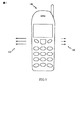
図1は、本開示の力誘導技法を組み込んだ手持ち式のデバイス100の典型的な実施形態を例示する。図1では、手持ち式のデバイス100は、携帯電話(mobile phone)として示されている。本開示の手持ち式のデバイスは、必ずしも携帯電話である必要はなく、一般に、例えば携帯情報端末(PDA)、パーソナルナビゲーションデバイス、スマートフォン、などの任意のタイプの手持ち式デバイスであり得ることを、当業者は十分理解するだろう。そうした代わりの典型的な実施形態は、本開示の範囲内であると考慮されている。
FIG. 1 illustrates an exemplary embodiment of a
本開示によると、手持ち式デバイス100は、手持ち式デバイス100の(図1中に示されていない)ユーザに対して、触知的に、かつ/または、運動感覚的に(kinesthetically)、知覚可能である、力のインパルスを生成するように構成可能である。そうした物理的インパルスは、例えば、環境の物理的制限、あるいはユーザの物理的障害、が原因で、その他の視覚あるいは可聴の指示があまり有効ではない場合、役に立ち得る。図1では、手持ち式デバイス100は、ユーザに触知的に知覚可能な手持ち式デバイス100の左側に対して、例えば、1つまたは複数の鋭い物理的インパルス110、あるいは「打撃(knock)」、を生成し得る。同様に、手持ち式デバイスは、手持ち式デバイス100の右側に対して、類似の打撃120を生成し得る。典型的な実施形態では、左打撃110は、手持ち式デバイス100のユーザに対して左方向を合図し得、一方で、右打撃120は、右側へ方向を合図し得る。代わりの典型的な実施形態では、手持ち式デバイス100の右部分、上部分、下部分、前部分、後部分、あるいは任意のローカル部分に対する指向性のあるインパルスが同様に生成され得、ユーザによって感じられ得る、ことは、十分理解されたい。
According to the present disclosure, the
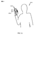
図1Aは、本開示に従う手持ち式パーソナルナビゲーションデバイス100A内の本開示の典型的な実施形態を例示する。ここで留意すべきは、図1Aが、ナビゲーションデバイスに本開示の範囲を限定することを意味するわけではなく、例示目的のためだけに示されている、ことである。図1Aでは、デバイス100Aは、ユーザ101Aの現在位置と関連するユーザ101Aによって指定された目標位置を決定するパーソナルナビゲーションデバイスとして構成されている。ナビゲーションデバイスによる現在位置および目標位置の決定は当該技術分野では周知であり、例えば、全地球測位システム(GPS:global positioning system)からの衛星信号を利用し得る、ことは十分理解されたい。ユーザ101Aを目標位置へ案内するために、デバイス100Aは、図1A中の120Aで例示されたようにデバイス100Aの側面に1つまたは複数の打撃や指向性のインパルスを生成し得る。図1Aに示された典型的な実施形態では、打撃120Aはデバイス100Aの左側に生成され、ユーザが目標位置に到達するためには左側に進むべきである、ことを指示する。
FIG. 1A illustrates an exemplary embodiment of the present disclosure within a handheld
図2は、本開示に従う力誘導技法を使用して触知的に知覚可能な物理的インパルスを生成するための機構の典型的な実施形態200を例示する。図2では、筐体(chassis)201は、機構200のコンポーネントが実装され得るところに提供される。筐体201は、例えば、図1に示されたように手持ち式デバイス100の物理的な筐体であり得る。あるいは、筐体201は、手持ち式デバイス100の分離筐体上に順番に実装され得る。
FIG. 2 illustrates an
筐体201は、固定の機械的支持210に結合され、それは、図2中に中空チューブとして示されている。チューブ210は、縦座標軸250(ここでは「第1軸」とも呼ばれる)に沿って中空(hollow)である。N極(N)およびS極(S)を有する磁気要素220は、チューブ210の内側に存在し得る。典型的な実施形態では、チューブ210の内側は真空を含み得、また、磁気要素220は軸250に沿って移動するように強いられ得る。図2では、変数xは、軸250に沿ったチューブ210の中心に関連する磁気要素220の中心の正味の(net)横変位を説明し、チューブ210の中心はx=0に対応している。縦座標軸は本開示の範囲を限定するように意味するわけではなく、説明目的のためだけに示されている、ことを当業者であれば十分理解するだろう。例えば、代わりの典型的な実施形態では、縦座標軸の中心はチューブ210上の任意の点を参照し得る。
The
典型的な実施形態では、チューブ210の内部は、例えばPTFEすなわち「テフロン(登録商標)(Teflon(登録商標))」のような低摩擦物質で覆われ得るか、潤滑油(lubricant)で満たされ得る。チューブ210の周りに巻かれている(wound)のは、1組または複数組の電気的に伝導する巻きコイルであり、そのうち3個のコイル240、241、242は図2中の断面内に示されている。第1コイル240の説明は、これ以降与えられ、同様の説明が、コイル241、242、および、代わりの典型的な実施形態の任意のその他の数のコイルに対して適用され得る。
In an exemplary embodiment, the interior of
第1コイル240は少なくとも1回は巻かれ、できればチューブ210の周りに複数回巻かれるのが好ましい。第1コイル240の第1端240.1および第2端240.2は、電流制御ブロック218に結合されている。電流の流れは図2中に示されており、240(a)は断面の平面への電流の流れを表し、240(b)は断面の平面からの電流の流れを表す。ブロック218は、第1コイル240を通って流れる電流を制御する。コイル241およびコイル242は、同様にブロック218に結合された端を有し、ブロック218によって生成された電流をサポートし得る。ブロック218は、順番に、エネルギーソース215へ結合される。エネルギーソース215は、電流制御ブロック218を通ってコイル240、241、242のいずれかを通って、電流を生成するためにエネルギーを供給し得る。特定の典型的な実施形態では、エネルギーソース215は、また、例えば図5に関してこれ以降さらに説明されるように、コイル240、241、242から生成されたエネルギーを格納し得る。
The
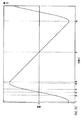
図3A、図3B、図3Cは、図2の機構200に関して、それぞれ、典型的な電流、変位、速度プロファイルを例示する。詳細には、図3Aは、横軸に沿って左から右へ時間の経過を示す時間(t)に対して、コイル240、241、242の1個または複数個を通る電流のプロットを例示する。電流、力、加速度はお互いに比例するように見込まれているので、それらは単純化のために1つの垂直軸上に示されている、ことは十分理解されたい。図3Bおよび図3Cでは、磁気要素220の変位および速度が時間(t)に対してそれぞれプロットされており、対応する電流は図3A中に示されたように想定している。図3A、図3B、図3Cは、本開示の範囲を示された任意の特定の電流、変位、あるいは速度のプロファイルに限定するように意味されているわけではなく、例示目的のためだけに示されている、ことを十分理解されたい。
3A, 3B, and 3C illustrate typical current, displacement, and velocity profiles, respectively, for the
「初期」時間に対応するように任意にt=t1と固定し、図3Bから、磁気要素220が最初にx=x1に位置しているとわかり、それは、チューブ210の中心x=0の左に位置している。さらに、図3Cは、磁気要素220が最初に時間t=t1で負の速度で(つまり、負のx方向で、あるいは、図2に関してチューブの左へ)移動する、ことを示している。
Arbitrarily fixed t = t1 to correspond to the “initial” time, and from FIG. 3B it can be seen that the
図3A中の電流プロファイルを参照すると、時間t=t1からt=t5まで、正の電流がコイル内に存在し、それは、電流制御ブロック218によって生成され得る。t=t1からt=t5の間に存在するようにコイルを通る正味の電流が、チューブ210内で磁場を生成し、それによって、磁気要素220上に力および対応する正の加速度を生成する、ことは十分理解されるだろう。その結果、磁気要素220の速度は図3C内で増加しているように見え、一方で磁気要素220の変位は図3B内に示されたように変化するように示されている。詳細には、図3Bでは、磁気要素220は、t=t1でx=x1から、t=t3でx=x3の一番左端へ移動しているように見え、ここで磁気要素220は方向を反転し、t=t3で正のx方向へ移動を開始し、t=t5まで正のx方向で加速を続ける。時間t=t1からt=t5までの間、磁気要素220は、コイル内の正電流に応答して、正のx方向で加速するように理解され得る。
Referring to the current profile in FIG. 3A, from time t =
時間t=t5からt=t8まで、例えば、電流制御ブロック218によって指揮されたように、反対極性の電流が印加される。この電流内の変化は、チューブ210内に存在する磁場中の対応する変化に付随して起きるだろう。それらに対応して、磁気要素220は、図3B中のt=t7でx=x7の一番右端へ、x=x1から右へ移動し続けている間は、t=t5からt=t8まで図3C中で負の加速を経験するように見える。t=t7で、磁気要素220は、方向を反転し、負のx方向で印加されている持続力が原因で、負のx方向内で移動を始める。t=t7からt=t8まで、磁気要素は、再度t=t8でx=x1に戻るまで、負のx方向で移動し続ける。
From time t = t5 to t = t8, a current of opposite polarity is applied, for example, as directed by
示された典型的な実施形態では、t=t6からt=t8までの負の加速度の大きさは、t=t2からt=t4までの加速度の大きさよりも小さく、それによって、ユーザに、正のx方向で正味の指向性のインパルスを感じさせる。一般に、一方向の磁気要素の最大加速が他方向の磁気要素の最大加速よりも大きい場合、そうした指向性のインパルスが生成されるだろう、ことは十分理解されたい。さらに、図3A中のt=t1からt=t8までの波形が、1サイクルを形成するように考慮され得、必要に応じて周期的な一連の指向性のインパルスを生成するために複数サイクルをこえて繰り返されうる、ことは十分理解されたい。 In the exemplary embodiment shown, the magnitude of the negative acceleration from t = t6 to t = t8 is less than the magnitude of the acceleration from t = t2 to t = t4, thereby allowing the user to Impress a net directivity impulse in the x direction. It should be appreciated that, in general, such directional impulses will be generated if the maximum acceleration of a magnetic element in one direction is greater than the maximum acceleration of a magnetic element in the other direction. Furthermore, the waveform from t = t1 to t = t8 in FIG. 3A can be considered to form one cycle, and multiple cycles can be used to generate a periodic series of directional impulses as needed. It should be fully understood that it can be repeated over and over.
コイル240、241、および242のうちの1個だけに関する典型的な電流プロファイルが図3A中に示されているが、機構200に関してコイル240、241、242の全ての独立電流プロファイルを同時に制御することによって合成(composite)電流プロファイルが生成され得る、ことを当業者であれば十分理解するだろう。例えば、複数のコイルが図2A中に示されたようにチューブ210の軸に沿って分布され得、チューブ210の軸を介して磁気要素220の変位プロファイルのより良い制御を可能にするように、順々に独立してスイッチされる。代わりの典型的な実施形態では、図2中に示された、より少ないコイルか、あるいは3個より多くのコイルが簡単に適応され得る、ことをさらに理解されたい。そうした代わりの典型的な実施形態は、本開示の範囲内であると考慮されている。
Although a typical current profile for only one of
図3A、図3B、図3Cから、特定の時間間隔を介して電流プロファイルを能動的に制御することによって、これに対して磁気要素220の変位プロファイルはそうした時間間隔を介して制御され得る、ことは十分理解されたい。逆に、(例えば、ユーザの動き、押すこと(jostling)による磁気要素220の動き、など)能動的な電流制御が原因ではない磁気要素220の変位の変化は、ファラデー(Faraday)の電磁誘導の法則に従って、コイル、あるいは複数のコイル内で電流を誘導し得る。典型的な実施形態では、そうしたその他の物理的な力が原因の磁気要素220の動きによって生成されたコイル内の電流は、これ以降さらに説明されるように、エネルギーに関して収穫され得る。
From FIG. 3A, FIG. 3B, FIG. 3C, by actively controlling the current profile through a specific time interval, the displacement profile of the
図4A、図4B、図4Cは、図2の機構200に関する代わりの典型的な電流、変位、速度のプロファイルを例示する。また、図4A、図4B、図4Cは、本開示の範囲を示された任意の特定の電流および/または変位のプロファイルに限定するように意味するわけではなく、例示目的のためだけに示されている、ことを理解されたい。
4A, 4B, and 4C illustrate alternative exemplary current, displacement, and velocity profiles for the
図4A、図4B、図4Cでは、時間t=T1’からt=T2’まで、示されたコイルを通る電流は電流制御ブロック218によって能動的に制御されており、その他の力が原因で磁気要素220によって生成された電流は、無視できると想定される。この時間間隔は、また、「能動的な」期間と呼ばれる。能動的な期間中に、図4Bに示されたように磁気要素220の変位プロファイル中の変化は、主に電流制御ブロック218による電流の能動的な生成によって引き起こされる。
In FIGS. 4A, 4B, and 4C, from time t = T1 ′ to t = T2 ′, the current through the indicated coil is actively controlled by the
時間t=T2’からt=T3’まで、示されたコイルを通る電流は、電流制御ブロック218によって能動的には制御されず、磁気要素220上のその他の力は、示されたコイル電流内の変化を生じさせると想定されている。この時間間隔は、また、「受動的な」期間と呼ばれる。受動的な期間中に、図4A中に示されたように磁気要素220の電流プロファイルは、図4B中に示されたように磁気要素220の変位プロファイル内の変化によって引き起こされる。
From time t = T2 ′ to t = T3 ′, the current through the indicated coil is not actively controlled by the
典型的な実施形態では、受動的な期間中のコイル電流内の変化は、例えば、図5に関してさらに記されたように電流制御ブロック218内の収穫機構、を使用してエネルギーに関して収穫され得る。
In an exemplary embodiment, changes in coil current during a passive period can be harvested in terms of energy using, for example, a harvesting mechanism in
図5は、能動期間中に希望の電流プロファイルを生成すること、ならびに、受動期間中に電流からエネルギーを収穫すること、の両方が可能な、エネルギーソース215.1および電流制御ブロック218.1の典型的な実施形態を例示する。 FIG. 5 illustrates an energy source 215.1 and current control block 218.1 that can both generate a desired current profile during the active period and harvest energy from the current during the passive period. Exemplary embodiments are illustrated.
図5では、ブロック218.1は、能動期間中の能動電流生成ブロック510か、受動期間中の収穫回路520か、のどちらかに対してコイル240の端240.1および240.2を選択的に結合する二重端末スイッチング要素501を含んでいる。収穫回路520が、受動期間中に磁気要素220の運動エネルギーから電気エネルギーを収穫し、収穫された電気エネルギーで再充電可能エネルギーソース215.1を充電する、ように構成され得る、ことは十分理解されたい。スイッチング要素501は第1コイル240に関して端240.1および240.2のみをスイッチングするものとして示されているが、スイッチング要素は、また、追加のコイル241、242、ならびに、本開示に従う明白に示されていないその他のコイルを簡単に適応させ得る、ことは十分理解されたい。
In FIG. 5, block 218.1 selects the ends 240.1 and 240.2 of
図5中のスイッチング要素501を表す記号は、本開示の範囲をスイッチング要素の任意の特定のインプリメンテーションに限定することを意味するわけではなく、スイッチング要素501の機能を例示するためだけに使用されている、ことは十分理解されたい。そうしたスイッチング要素が、例えば、機械的に、あるいは電気的に、トランジスタおよび/またはその他の回路要素などを使用してインプリメントされ得るような複数種類の方法がある、ことを当業者であれば理解するだろう。そうした典型的な実施形態は、本開示の範囲内であると考慮されている。
The symbols representing switching
能動電流生成ブロック510は、能動期間中にコイル240に関する希望の電流プロファイルのデジタル表現512aを生成するための論理制御ユニット512を含んでいる。デジタル表現512aは、可変電流制御ブロック514へ結合され、それは、希望の電流のデジタル表現512aをアナログ電流514aへ変換し得、それは、その後コイル240へ供給される。能動期間中に、電力は、アナログ電流514aでコイル240を駆動するために、可変電流制御ブロック514に制御された回路を通って再充電可能エネルギーソース215.1から引かれる。
The active
典型的な実施形態では、可変電流制御ブロック514は、例えば、その短期間の平均値が希望の電流に対応するような電流を生成するためのパルス幅変調回路、を使用してインプリメントされ得る。代わりの典型的な実施形態では、可変電流制御ブロック514は、また、例えばデジタルアナログ変換器(DAC)を含み得る。デジタルに特定されたプロファイルに従うアナログ電流を生成するための複数の技法があり、そうした典型的な実施形態は本開示の範囲内であると考慮されている、ことは当業者であれば十分理解するだろう。
In an exemplary embodiment, the variable
受動期間中に、収穫回路520は、コイルから電気エネルギーを収穫する。図5では、充電回路が、出力電圧を生成するようにコイル240から電流を整流する整流器522を含むように示されている。典型的な実施形態では、整流器522は、正の電流と負の電流の両方を整流することが可能な当該技術分野では周知である双方向の整流器であり得る。出力電圧522aは、エネルギーソース215.1を充電するために使用され得る。したがって、受動期間中に、エネルギーは、再充電可能エネルギーソース215.1に供給される。エネルギーソース215.1は、例えば、再充電可能電池、コンデンサ、など、当該技術分野では周知である任意の再充電可能なエネルギーソースであり得る。
During the passive period, the
代わりの典型的な実施形態では、収穫回路520は、記載された機能を実行するために当業者のうちの一人に知られた任意の構造を使用してインプリメントされ得る。例えば、収穫回路520は、エネルギーソース215.1に関して出力電圧を生成するために当該技術分野では周知である電圧アップコンバータを代わりに含み得る。そうした代わりの典型的な実施形態は、本開示の範囲内であると考慮される。
In an alternative exemplary embodiment,
再充電可能エネルギーソース215.1は、また、指向性の力インパルスを生成するための機構200とは別の、手持ち式のデバイス100のモジュールにエネルギーを供給するために使用され得る、ことはさらに十分理解されたい。電流制御ブロック218.1および再充電可能エネルギーソース215.1が力インパルス生成機構200内で利用されている典型的な実施形態では、機構200は指向性インパルス生成ならびにエネルギー収穫の両方の利点(benefit)を提供し、それは、手持ち式デバイス100の全体的な電池寿命を好適に拡張し得る。
The rechargeable energy source 215.1 can also be used to supply energy to a module of the
ここで留意すべきは、図5は本開示の範囲を示されたブロックの任意の特定のインプリメンテーションに限定するように意味しているのではなく、例示目的のためだけに示されている、ことである。例えば、代わりの典型的な実施形態では、機構200は、図5に示された典型的な実施形態のエネルギー収穫能力を必ずしも組み込む必要はない。そうした代わりの典型的な実施形態は、本開示の範囲内であると考慮されている。
Note that FIG. 5 is not meant to limit the scope of the present disclosure to any particular implementation of the indicated blocks, but is shown for illustrative purposes only. That's it. For example, in an alternative exemplary embodiment, the
図6Aおよび図6Bは、本開示に従う方法の典型的な実施形態を例示する。 6A and 6B illustrate an exemplary embodiment of a method according to the present disclosure.
図6Aでは、ブロック610Aにおいて、方法600Aは、固定の支持を囲んでいる少なくとも1個のコイル中に電流を生成することを含んでいる。典型的な実施形態では、支持は、支持の第1軸に沿って移動可能な磁気要素へ結合されている。電流によって、磁気要素は、少なくとも1サイクルをこえて、第1軸に沿った一方向の磁気要素の最大加速が第1軸に沿った他方向の磁気要素の最大加速よりも大きくなるように、第1軸に沿って移動し得る。
In FIG. 6A, at
ブロック620Aにおいて、方法は、少なくとも1個のコイル中で電流を生成しないとき、少なくとも1個のコイルからエネルギーを収穫することを含む。
At
ブロック630Aにおいて、方法は、再充電可能エネルギーソース内に収穫されたエネルギーを格納することを含む。 At block 630A, the method includes storing harvested energy in a rechargeable energy source.
図6Bでは、ブロック610Bにおいて、方法600Bは、能動的な期間中に、固定の支持を囲んでいる少なくとも1個のコイル内で電流を生成すること、を含んでいる。典型的な実施形態では、支持は、支持の第1軸に沿って移動可能な磁気要素へ結合され、電流によって、磁気要素は第1軸に沿って移動する。
In FIG. 6B, at
ブロック620Bにおいて、受動的な期間中に、方法は、少なくとも1個のコイルからエネルギーを収穫することと、再充電可能エネルギーソース内に収穫されたエネルギーを格納することを含んでいる。
In
図7は、本開示に従う指向性のインパルスを生成するための機構の代わりの典型的な実施形態700を例示する。図7に示されたように、1個または複数個の補助磁石720、730は、チューブ210の端において供給され得る。例えば、補助磁石720はチューブ210の一端で物理的に固定され得、補助磁石730は他端で物理的に固定され得る。補助磁石720の極性は、それが磁気要素220の近い方の端に反発し、同様に補助磁石730に関しても反発するように、選ばれ得る。例えば、補助磁石720のN極(N)は磁気要素220のN極(N)へ向けて配向し、一方で、補助磁石730のS極(S)は磁気要素220のS極(S)へ向けて配向する。この方法では、磁気要素220が補助磁石720に近づくときはいつでも、磁気要素220をその初期位置とは反対に向けて押すだろう磁石720と220の間に斥力が生成されるだろう。
FIG. 7 illustrates an
図7は、1個または複数個のバイアス・バネ710a、710bが提供され得る、ことをさらに例示する。バイアス・バネ710aの一端が磁気要素220へ取り付けられ、一方で、他端は、チューブの一端、例えば磁石730の一端へ取り付けられる。同様に、バイアス・バネ710bの一端が磁気要素220へ取り付けられ、一方で、他端は、チューブの他端、例えば磁石720の一端へ取り付けられる。バイアス・バネ710a、710bは、それが動かされたときはいつでも、磁気要素220をその初期位置とは反対に押したり引いたりするように力を生成し得る。
FIG. 7 further illustrates that one or more bias springs 710a, 710b can be provided. One end of the
代わりの典型的な実施形態では、単一の磁石は、中心へ向けて磁気要素220をバイアスするためにチューブ210の中心で提供され得る。例えば、リング磁石は、その中心近く(例えば、図2によるとx=0)でチューブ210の周辺周りで包まれ得る。そうした代わりの典型的な実施形態は、本開示の範囲内であると考慮されている。
In an alternative exemplary embodiment, a single magnet may be provided at the center of the
図7に記述されたように1個または複数個のバイアス・バネおよび/または1個または複数個の補助磁石を提供することによって、機構700は、電流制御ブロック218に、磁石をその初期位置とは反対に持ってくるように、コイル240、241、242内で少ない電流を生成させ、このようにして電力消費および/または制御方法の複雑さを減少する。
By providing one or more bias springs and / or one or more auxiliary magnets as described in FIG. 7,
特定の典型的な実施形態では、1個または複数個の補助磁石が、1個または複数個のバイアス・バネと共に必ずしも使用される必要は無く、どちらの特徴も別の方に独立に組み込まれることができる、ことは十分理解されたい。代わりの典型的な実施形態では、磁気要素220は、生成された指向性力インパルスがユーザによってより明白に感じられ得るように、磁気要素220の全マスを増加させるように(示されていない)非磁気マスを具体的に組み込み得る。例えば、そうした非磁気マスは、手持ち式デバイス100の電池であり得る。代わりの典型的な実施形態では、1個よりも多くの磁気要素220が、また、組み込まれ得る。そうした代わりの典型的な実施形態は、本開示の範囲内であると考慮される。
In certain exemplary embodiments, one or more auxiliary magnets need not necessarily be used with one or more bias springs, both features being independently incorporated into the other. It should be fully understood that you can. In an alternative exemplary embodiment, the
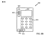
上記の動作誘導技法および機構は、例えば、モバイルデバイス内で使用され得る。図8Aは、1つの実施形態に従う動的フィードバックを提供するためのモバイルデバイスを例示する図面である。モバイルデバイス800は、ディスプレイ802および入力デバイス804を含んでいる。1つの実施形態によると、モバイルデバイス800はセルラー方式携帯電話であり、入力デバイス804はキーパッドである。入力デバイス804は、また、トラッキングパッド、トラックボール、カーソルキー、あるいはその他の入力デバイスであり得る。また、ディスプレイ802は、タッチ感度が良いものであり得る。
The motion guidance techniques and mechanisms described above can be used, for example, within a mobile device. FIG. 8A is a drawing illustrating a mobile device for providing dynamic feedback according to one embodiment.
モバイルデバイス800は、動作誘導デバイス810を含んでいる。1つの実施形態によると、動作誘導デバイス810は、マス812を含み、それは、動作を生成するために動作誘導デバイス810内で加速される。マス812は、動作誘導デバイス810内で(示されていない)物体(object)をタップし得る。1つの実施形態によると、マス812は、およそ1/16オンスから1/2オンスの間である。物体およびマス812の材料に基づいて、ノイズが作られ得る。例えば、マス812が磁石であり物体が金属性である場合、マス812が物体をタップするときに可聴音が作られ得る。
1つの実施形態によると、設定が、マス812の加速を制御するためにモバイルデバイス800内で利用可能である。例えば、動作誘導デバイス810は、物体をタップするためにマス812を加速するように構成され得る。動作誘導デバイス810が静音モード用に構成される場合、マス812は物体をタップしないように加速され減速され得る。
According to one embodiment, settings are available within
1つの実施形態では、動作誘導デバイス810は、モバイルデバイス800のユーザに受信されたメッセージのタイプ、内容、あるいはコンテキストを伝えるようにモバイルデバイス800によって制御される。受信されたメッセージは、例えば、ショートテキストメッセージング(SMS)サービスメッセージ、マルチメディアメッセージングサービス(MMS)メッセージ、電子メールメッセージ、ボイスメールメッセージ、見逃された呼に関するメッセージ、および、ナビゲーションのための方向を含んでいるメッセージ、を含み得る。例えば、モバイルデバイス800は、動的力フィードバックを提供することによってメッセージの異なるコンテキストをユーザに通知するように動作誘導デバイス810を制御し得る。例えば、タッピング周波数は、およそ0から25ヘルツ(Hertz)まで変化し得る。警告がより緊急になるような1つの実施形態によると、タッピング周波数は増大する。例えば、着呼がモバイルデバイス800に到着するとき、第1ベルは5Hzで、第2ベルは10Hzで、第3ベルは15Hzである。
In one embodiment, the
また、動作誘導デバイス810によるタッピングの振幅は、モバイルデバイス800によって変化し得る。例えば、動作誘導デバイス810によるマス812の加速は、増大され得るか、減少され得る。1つの実施形態によると、警告がより緊急になるにつれ、タッピング振幅は増大する。
In addition, the amplitude of tapping by the
モバイルデバイス800は、ユーザに情報を伝えるように動作誘導デバイス810を制御し得る。例えば、動作誘導デバイス810は、ユーザに対するメッセージの異なるシーケンスをタップするように制御され得る。1つの実施形態によると、タッピングシーケンスは、ユーザがディスプレイ802を眺めることなく、発呼者(incoming caller)(あるいは発呼者のグループ)を識別するように定義される。例えば、5のタップのシーケンスは家族が呼んでいることを指示し、3のタップのシーケンスは、仕事仲間が呼んでいることを指示する。別の実施形態によると、タッピングシーケンスは、モバイルデバイス800で受信されたメッセージタイプを識別するように定義される。例えば、ショートメッセージサービス(SMS)メッセージが受信される場合、動作誘導デバイス810は1回のロングタップに続いて2回のショートタップを実行するように作動するが、電子メールメッセージが受信される場合、動作誘導デバイス810は、1回のショートタップに続いて2回のロングタップを実行するように作動する。
The
モバイルデバイス800は、内容をユーザに伝えるように動作誘導デバイス810を制御し得る。例えば、動作誘導デバイス810は、受信されたメッセージを伝えるために、異なるシーケンス、異なる振幅、あるいは異なる周波数をタップするように制御され得る。1つの実施形態によると、小さい振幅を持つショートタップのシーケンスは、「目的地に無事に到着した」ことを指示するメッセージであり得る。代わりに、大きい振幅を持つロングタップのシーケンスは、「失敗、指示が必要」を指示するメッセージであり得る。こうしたメッセージは、例えば、親の心情を楽にするために、子供から親へ送られ得る。親がディスプレイ802を眺めることなく情報を伝えることは、親の利便性を増大させる。
The
動作誘導デバイス810により提供される動的フィードバックは、ユーザがディスプレイ802を見ることなくユーザに情報を提供する。広範囲の情報は、例えば、着呼、発呼者id、発呼者グループ、着信メッセージ、メッセージタイプ、電池残量低下、カレンダーリマインダ、音楽プレイヤー広告、および、測位位置(例えばGPS)方向などの、動作誘導デバイスによって伝えられ得る。各々のこうした警告および追加警告は、ディスプレイ802と入力デバイス804の相互作用を通して、モバイルデバイス800上でソフトウェアを通して構成され得る。また、動作誘導デバイス810は、マス812の加速を実行するために制限された量の電力を消費し得る。
The dynamic feedback provided by the
モバイルデバイス800内の動的力フィードバックは、多次元で適用され得る。図8Bは、1つの実施形態に従う、複数方向に動的フィードバックを提供するためにモバイルデバイスを例示する図面である。モバイルデバイス800は、また、マス822を有する第2動作誘導デバイス820を含み得る。動作誘導デバイス820は、動作誘導デバイス810と同一でも良いし、異なっていても良い。1つの実施形態によると、動作誘導デバイス820は、動作誘導デバイス810からおよそ90度角度を付けて配向している。この配置では、モバイルデバイス800は、多次元でユーザに動的フィードバックを提供し得る。2台の動作誘導デバイスだけが例示されているが、モバイルデバイス800は追加の誘導デバイスを含み得る。
Dynamic force feedback within the
モバイルデバイス800は、モバイルデバイス800の異なる方向に沿って異なる警告を提供するように構成され得る。例えば、ユーザは2回の水平タップで電子メールメッセージの到着を通知され得、また、ユーザは、2回の垂直タップでテキストメッセージの到着を通知され得る。1つの実施形態によると、多次元動的力フィードバックは、地理的方向に配向した力フィードバックを提供することでユーザを案内する。別の実施形態によると、モバイルデバイス800は、動作誘導デバイス810、820の両方を作動させ、動的力フィードバックを提供する。例えば、ナビゲーションでは、ユーザは、動作誘導デバイス810、820の両方を作動することで上と左に方向付け得る。
モバイルデバイス800は、モバイルデバイス800が位置している環境に基づいて、動作誘導デバイス810および動作誘導デバイス820を通って動的フィードバックをタップすることを提供するように構成され得る。図8Cは、1つの実施形態に従う、動的フィードバックを提供すること、および、モバイルデバイス周りの環境を感じること、に関するモバイルデバイスを例示することを描いている。モバイルデバイス800は、例えば、加速度センサ(accelerometer)、コンパス、傾角計(inclinometer)、カメラ、熱センサ、タッチセンサ、近接センサ、あるいは圧力センサ、などのセンサ830を含んでいる。1つの実施形態によると、センサ830は、モバイルデバイス800の方向を決定するための加速度センサである。センサ830は、ユーザに提供するために動的フィードバックを選択する際に、モバイルデバイス800へその他の情報を提供し得る。別の実施形態によると、センサ830は、指向性ガイダンスに関して動的フィードバックを提供する際に、ユーザの地理的配向を決定するためのコンパスである。別の実施形態によると、センサ830は、モバイルデバイス800がユーザのポケットに位置しているかどうかを決定するための温度計である。温度計は、モバイルデバイス800に、モバイルデバイスのどちらの側面がユーザに面しているかに関する情報を提供し得る。別の実施形態によると、センサ830は、ユーザがモバイルデバイス800に近接しているかどうかを検出するための近接センサである。例えば、モバイルデバイス800がユーザの耳の近くに保たれている場合、動作誘導デバイス810、820の振幅は減少され得る。
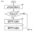
図9Aは、1つの実施形態に従う、多次元内で、動的フィードバックを提供するためのモバイルデバイスの動作を例示するフローチャートである。ブロック905において、モバイルデバイス800がユーザに警告する原因となる事象が生じる。モバイルデバイス800は、ユーザに動的力フィードバックを通して警告させる特定の事象と共に、ソフトウェアを通して、構成され得る。ブロック910において、モバイルデバイス800は、モバイルデバイス800の方向を決定するためにセンサ830に質問する(query)。モバイルデバイスがおよそ水平方向に配向する場合、モバイルデバイス800は、ブロック915に進み、動作誘導デバイス810を通して動的フィードバックを提供する。モバイルデバイスがおよそ垂直方向に配向する場合、モバイルデバイス800は、ブロック920に進み、動作誘導デバイス820を通して動的フィードバックを提供する。
FIG. 9A is a flowchart illustrating the operation of a mobile device to provide dynamic feedback in multiple dimensions, according to one embodiment. At
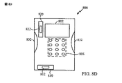
追加情報が、ユーザに動的フィードバックを供給するためにモバイルデバイス800に提供され得る。図8Dは、1つの実施形態に従う、モバイルデバイス上で、動的フィードバックを提供すること、および圧力を知覚することに関するモバイルデバイスを例示する図面である。モバイルデバイス800は、圧力センサ832を含んでいる。1つの実施形態によると、圧力センサ832は、いかに強くユーザがモバイルデバイス800を握るかを判断する。モバイルデバイス800は、圧力センサ832からの情報に基づいて動作誘導デバイス810および動作誘導デバイス820を通って提供されたタッピングの振幅および/または周波数を変化させ得る。例えば、ユーザがモバイルデバイス800を強く掴む場合、動作誘導デバイス810および動作誘導デバイス820のタッピングの振幅は増大する。
Additional information may be provided to the
図9Bは、別の実施形態において、動的フィードバックを提供するためのモバイルデバイスの動作を例示するフローチャートである。ブロック925において、遠隔ユーザから受信されたメッセージのタイプ、内容、および/または、コンテキストは、デバイスのローカルユーザへ伝わるように決定される。ブロック930において、動的力フィードバックは、メッセージのタイプ、内容、あるいはコンテキストに応じて提供される。
FIG. 9B is a flowchart illustrating the operation of a mobile device to provide dynamic feedback in another embodiment. At
動的フィードバックは、ナビゲーションデバイス内で提供され得る。図10は、1つの実施形態に従う、動的フィードバックおよび方向を提供するためのモバイルデバイスを例示する図面である。ナビゲーションデバイス1000は、ディスプレイ1002を含んでいる。ディスプレイ1002は、視覚方向あるいは地図を示し得る。1つの実施形態によると、ナビゲーションデバイス1000は、全地球測位システム(GPS)デバイスである。
Dynamic feedback can be provided within the navigation device. FIG. 10 is a drawing illustrating a mobile device for providing dynamic feedback and direction according to one embodiment. The
ナビゲーションデバイス1000は、また、マス1012を含む動作誘導デバイス1010およびマス1022を含む動作誘導デバイス1020を含んでいる。1つの実施形態によると、動作誘導デバイス1010は、動作誘導デバイス1020に対しておおよそ直交して配向している。
The
方向は、ディスプレイ1002を通してナビゲーションデバイス1000内へ入り得るか、ナビゲーションデバイス1000へダウンロードされ得る。方向はユーザへ提供されるので、動的フィードバックは動作誘導デバイス1010、1020を通して提供され得る。例えば、ユーザへの電流方向が右を向いている場合、動作誘導デバイス1010は右をタップし得る。あるいは、ユーザへの電流方向が左を向いている場合、動作誘導デバイス1010は左をタップし得る。ユーザへの電流方向が後ろを向いている場合、動作誘導デバイス1020は下をタップし得る。1つの実施形態によると、動作誘導デバイス1010、1020により提供されたタッピングの振幅あるいは周波数は、方向が実行される位置へユーザが接近するにつれて増大する。例えば、ユーザが、ユーザが右へ曲がるだろう交差点に接近すると、動作誘導デバイス1010、1020のタッピング振幅は増大する。
The direction can enter the
1つの実施形態によると、ナビゲーションデバイス1000は歩行者ナビゲーションのために使用される。例えば、都市を歩いているユーザは、方向をナビゲーションデバイス1000にプログラムした後、ユーザのポケットにナビゲーションデバイス1000を入れる。ユーザが都市を歩いていると、ユーザはナビゲーションデバイス1000からどの方向を歩くべきかを指示するタッピングを受け取る。1つの実施形態によると、ナビゲーションデバイス1000は、ナビゲーションデバイス1000の配向を決定することと、適切な動作誘導デバイス1010、1020、を作動させることと、に関するセンサを含んでいる。別の実施形態によると、ナビゲーションデバイス1000は、ナビゲーションデバイス1000に内蔵された測位位置受信機から配向を決定する。
According to one embodiment, the
動的フィードバックは、ハンディキャップ支援を提供するために役立ち得る。例えば、ナビゲーションデバイス1000からの動的フィードバックは、盲目の人(the blind)を案内するために使用され得る。1つの実施形態によると、動的フィードバックは、杖(cane)、ベルト、あるいは腕時計に組み込まれる。
Dynamic feedback can help to provide handicap assistance. For example, dynamic feedback from the
モバイルデバイス内で動的フィードバックを提供することは、ユーザがモバイルデバイスのディスプレイを眺めることなく、ユーザに情報を提供することでユーザの経験を改良する。例えば、方向、発呼通知、発呼者id、および、着信メッセージは、動作誘導デバイスにより提供されるタップのシーケンスでユーザに伝えられ得る。また、動作誘導デバイスによって提供されるタッピングは、ユーザの注意を引くためのより自然で人間のような方法である。したがって、タッピングは、振動させるのとは対照的に、モバイルデバイス上で生じる事象へユーザの注意を向けやすい。 Providing dynamic feedback within the mobile device improves the user experience by providing information to the user without the user looking at the display of the mobile device. For example, the direction, call notification, caller id, and incoming message may be communicated to the user in a sequence of taps provided by the motion induction device. Also, the tapping provided by the motion induction device is a more natural and human-like way to get the user's attention. Thus, tapping tends to direct the user's attention to events that occur on the mobile device as opposed to vibrating.
図11は、本開示の1つの実施形態が好適に使用され得る典型的な無線通信システム1100を示す。例示の目的で、図11は、3台の遠隔ユニット1120、1130、1150、および、2つの基地局1140、を示す。無線通信システムがより多くの遠隔ユニットおよび基地局を有し得る、ことは理解されたい。遠隔ユニット1120、1130、1150は、それぞれ、動作誘導デバイス1125A、1125C、1125B、を含み、それらは上で検討された実施形態である。図11は、基地局1140から遠隔ユニット1120、1130、1150へのフォワードリンク信号1180と、遠隔ユニット1120、1130、1150から基地局1140へのリバースリンク信号1190と、を示す。
FIG. 11 illustrates an exemplary
図11では、遠隔ユニット1120は携帯電話として示され、遠隔ユニット1130はポータブルコンピュータとして示され、遠隔ユニット1150は無線ローカルループシステム中のコンピュータとして示されている。例えば、遠隔ユニットは、セルラー方式携帯電話(cell phone)、携帯電話(mobile phone)、コンピュータ、セットトップボックス、音楽プレイヤ、映像プレイヤ、娯楽ユニット、手持ち式パーソナル通信システム(PCS)ユニット、携帯情報端末などのポータブルデータユニット、あるいは、検針装置などの固定位置データユニット、であり得る。図11は本開示の教示に従う遠隔ユニットを例示しているが、本開示は、こうした典型的に例示されたユニットに限定されるわけではない。本開示は、スタックICを含む任意のデバイス中で適切に使用され得る。
In FIG. 11,
情報および信号がさまざまな異なる技術および技法のいずれかを使用して表され得ることを、当業者であれば理解するだろう。例えば、上の記述全体を通して参照され得るデータ、命令群、コマンド、情報、信号、ビット、シンボル、およびチップは、電圧、電流、電磁波、磁場あるいは磁気粒子、光電場あるいは光学粒子、あるいはそれらの任意の組み合わせで表され得る。 Those of skill in the art will understand that information and signals may be represented using any of a variety of different technologies and techniques. For example, data, instructions, commands, information, signals, bits, symbols, and chips that can be referenced throughout the above description are voltages, currents, electromagnetic waves, magnetic fields or magnetic particles, photoelectric or optical particles, or any of them It can be represented by a combination of
本明細書に開示された典型的な実施形態に関連して記述された様々な例証となる論理ブロック、モジュール、回路、およびアルゴリズムステップは、電子ハードウェア、コンピュータソフトウェア、あるいは両方の組み合わせとしてインプリメントされ得る、ことを、当業者であればさらに十分理解するだろう。このハードウェアとソフトウェアの互換性を明白に示すために、様々な例証となるコンポーネント、ブロック、モジュール、回路、およびステップは、それらの機能の観点から一般に上で説明されている。そうした機能がハードウェアとしてインプリメントされるかソフトウェアとしてインプリメントされるかは、システム全体に課される設計の制約および特定のアプリケーションに依存する。当業者は各々の特定のアプリケーションに関して様々な方法で記述された機能をインプリメントし得るが、そうしたインプリメンテーションの決定は、本開示の典型的な実施形態の範囲から逸脱する原因であると解釈されるべきではない。 Various illustrative logic blocks, modules, circuits, and algorithm steps described in connection with the exemplary embodiments disclosed herein are implemented as electronic hardware, computer software, or a combination of both. Those of ordinary skill in the art will better understand that. To clearly illustrate this hardware and software compatibility, various illustrative components, blocks, modules, circuits, and steps have been described above generally in terms of their functionality. Whether such functionality is implemented as hardware or software depends on the design constraints imposed on the overall system and on the particular application. Those skilled in the art may implement the functions described in various ways for each particular application, but such implementation decisions are interpreted as deviating from the scope of the exemplary embodiments of the present disclosure. Should not.
本明細書に開示された典型的な実施形態に関連して記述された様々な例証となる論理ブロック、モジュール、および回路は、汎用プロセッサ、デジタル信号プロセッサ(DSP)、特定用途向け集積回路(ASIC)、フィールドプログラム可能型ゲートアレイ(FPGA)あるいはその他のプログラム可能型論理デバイス、ディスクリートゲートあるいはトランジスタ論理、ディスクリートハードウェアコンポーネント、あるいは、本明細書に記述された機能を実行するように設計された任意のそれらの組み合わせで、インプリメントされ得るか、実行され得る。汎用プロセッサはマイクロプロセッサであり得るが、代替案では、プロセッサは任意の従来のプロセッサ、コントローラ、マイクロコントローラ、あるいはステートマシーンであり得る。プロセッサは、また、例えば、DSPとマイクロプロセッサの組み合わせ、複数のマイクロプロセッサの組み合わせ、DSPコアに結合した1つまたは複数のマイクロプロセッサの組み合わせ、あるいは任意のその他のそうした構成、といった、計算デバイスの組み合わせとしてインプリメントされ得る。 Various illustrative logic blocks, modules, and circuits described in connection with the exemplary embodiments disclosed herein are general purpose processors, digital signal processors (DSPs), application specific integrated circuits (ASICs). ), Field Programmable Gate Array (FPGA) or other programmable logic device, discrete gate or transistor logic, discrete hardware components, or any designed to perform the functions described herein Can be implemented or implemented with these combinations. A general purpose processor may be a microprocessor, but in the alternative, the processor may be any conventional processor, controller, microcontroller, or state machine. A processor may also be a combination of computing devices such as, for example, a combination of a DSP and a microprocessor, a combination of multiple microprocessors, a combination of one or more microprocessors coupled to a DSP core, or any other such configuration. Can be implemented as:
本明細書に開示された典型的な実施形態に関連して記述されたアルゴリズムあるいは方法のステップは、ハードウェアにおいて、プロセッサに実行されたソフトウェアモジュールにおいて、あるいはその2つの組み合わせにおいて、直接的に具現化され得る。ソフトウェアモジュールは、ランダムアクセスメモリ(RAM)、フラッシュメモリ、読み取り専用メモリ(ROM)、電気的プログラム可能型ROM(EPROM)、電気的消去可能プログラム可能型ROM(EEPROM)、レジスタ、ハードディスク、リムーバブルディスク、CD−ROM、あるいは、当該技術分野において周知であるその他任意の形状の記憶媒体、に存在し得る。典型的な記憶媒体は、プロセッサが記憶媒体から情報を読み取ることができ、記憶媒体へ情報を書き込むことができるように、プロセッサへ結合される。代替案では、記憶媒体はプロセッサに不可欠であり得る。プロセッサおよび記憶媒体は、特定用途向け集積回路(ASIC)内に存在し得る。ASICは、ユーザ端末内に存在し得る。代替案では、プロセッサおよび記憶媒体はユーザ端末内にディスクリートコンポーネントとして存在し得る。 The algorithm or method steps described in connection with the exemplary embodiments disclosed herein may be implemented directly in hardware, in software modules executed on a processor, or in a combination of the two. Can be Software modules include random access memory (RAM), flash memory, read only memory (ROM), electrically programmable ROM (EPROM), electrically erasable programmable ROM (EEPROM), registers, hard disk, removable disk, It may reside on a CD-ROM or any other form of storage medium that is well known in the art. An exemplary storage medium is coupled to the processor such that the processor can read information from, and write information to, the storage medium. In the alternative, the storage medium may be integral to the processor. The processor and the storage medium may reside in an application specific integrated circuit (ASIC). The ASIC may be present in the user terminal. In the alternative, the processor and the storage medium may reside as discrete components in a user terminal.
1つまたは複数の典型的な実施形態では、記述された機能は、ハードウェア、ソフトウェア、ファームウェア、あるいはそれらの任意の組み合わせにおいてインプリメントされ得る。ソフトウェアでインプリメントされる場合、当該機能は、コンピュータ可読媒体上の1つまたは複数の命令あるいはコードとして、格納され得るか、あるいはそれらを介して伝送され得る。コンピュータ可読媒体は、ある場所から別の場所へコンピュータプログラムの転送を容易にする任意の媒体を含む、通信媒体とコンピュータ記憶媒体の両方を含んでいる。記憶媒体は、コンピュータによりアクセス可能な任意の利用可能な媒体であり得る。一例として、限定するわけではないが、そうしたコンピュータ可読媒体は、RAM、ROM、EEPROM、CD−ROMあるいはその他の光学ディスクストレージ、磁気ディスクストレージ、あるいはその他の磁気記憶デバイス、あるいは、命令群またはデータ構造の形式で希望のプログラムコードを搬送もしくは格納するために使用されることができ、コンピュータによりアクセスされることが可能な、任意のその他の媒体、を備え得る。また、任意の接続が適当にコンピュータ可読媒体と呼ばれる。例えば、ソフトウェアが、同軸ケーブル、光ファイバーケーブル、ツイステッドペア、デジタル加入者回線(DSL)、あるいは、赤外線、無線、マイクロ波などの無線技術を使用して、ウェブサイト、サーバ、あるいはその他の遠隔ソースから伝送される場合、同軸ケーブル、光ファイバーケーブル、ツイステッドペア、DSL、あるいは赤外線、無線、マイクロ波などの無線技術は媒体の定義に含まれる。本明細書に使用されたディスク(disk)およびディスク(disc)は、コンパクトディスク(disc)(CD)、レーザーディスク(登録商標)(disc)、光学ディスク(disc)、デジタル多用途ディスク(disc)(DVD)、フロッピー(登録商標)ディスク(disk)、およびブルーレイ(登録商標)ディスク(disc)を含んでおり、ここで、通常ディスク(disk)はデータを磁気的に再生し、一方でディスク(disc)はレーザを用いてデータを光学的に再生する。上の組み合わせも、また、コンピュータ可読媒体の範囲内に含まれるものとする。 In one or more exemplary embodiments, the functions described may be implemented in hardware, software, firmware, or any combination thereof. If implemented in software, the functions may be stored on or transmitted through as one or more instructions or code on a computer-readable medium. Computer-readable media includes both communication media and computer storage media including any medium that facilitates transfer of a computer program from one place to another. A storage media may be any available media that can be accessed by a computer. By way of example, and not limitation, such computer readable media can be RAM, ROM, EEPROM, CD-ROM or other optical disk storage, magnetic disk storage, or other magnetic storage device, or instructions or data structures Any other medium that can be used to carry or store the desired program code in the form of, and that can be accessed by a computer. Also, any connection is properly termed a computer-readable medium. For example, software can use a coaxial cable, fiber optic cable, twisted pair, digital subscriber line (DSL), or wireless technology such as infrared, wireless, microwave, etc. from a website, server, or other remote source When transmitted, coaxial cable, fiber optic cable, twisted pair, DSL, or wireless technologies such as infrared, wireless, microwave are included in the definition of the medium. Discs and discs used herein are compact discs (CDs), laser discs (discs), optical discs (discs), digital versatile discs (discs). (DVD), floppy disk (disk), and Blu-ray disk (disc), where the disk (disk) normally plays data magnetically while the disk ( disc) optically reproduces data using a laser. Combinations of the above should also be included within the scope of computer-readable media.
本開示およびその利点が詳細に説明されてきたが、添付された特許請求の範囲によって定義されたように本開示の技術から逸脱することなく多様な変更、置換、および代替が本明細書で行われることができる、ことは理解されたい。さらに、本出願の範囲は、本明細書に記述された、プロセス、機械、製造物、組成物、手段、方法およびステップの特定の実施形態に限定されるようには意図されていない。本開示から、本明細書に記述された実施形態に対応するものと実質的に同じ機能を実行するか、実質的に同じ結果を達成する、既存のあるいは後に開発される、プロセス、機械、製造物、組成物、手段、方法、あるいはステップが、本開示に従って利用され得る、ことを、当業者であれば容易に理解するだろう。したがって、添付された特許請求の範囲は、そうしたプロセス、機械、製造物、組成物、手段、方法、あるいはステップを、それらの範囲内に含むように意図されている。
以下、本願の出願当初の特許請求の範囲に記載の発明を付記する。
[C1] デバイスのローカルユーザに対して伝えるために遠隔ユーザから受信されたメッセージのタイプ、内容、およびコンテキストの少なくとも1つを決定することと、
前記メッセージの前記タイプ、前記内容、あるいは前記コンテキストに応じて、前記ローカルユーザに対して第1方向で動的力フィードバックを提供することと、
を備えた方法。
[C2] 前記動的力フィードバックが前記デバイスの前記ローカルユーザをタップすることを備える、[C1]の方法。
[C3] 受信されたメッセージの第1タイプに関する第1振幅の動的力フィードバックを提供することと、
受信されたメッセージの第2タイプに関する第2振幅の動的力フィードバックを提供することであって、前記第2振幅は前記第1振幅とは異なっている、第2振幅の動的力フィードバックを提供することと、
をさらに備えた、[C1]の方法。
[C4] 前記第1タイプの受信されたメッセージはテレフォンコールであり、前記第2タイプの受信されたメッセージはショートメッセージサービス(SMS)メッセージである、[C3]の方法。
[C5] 受信されたメッセージの第1タイプに関する第1周波数の動的力フィードバックを提供することと、
受信されたメッセージの第2タイプに関する第2周波数の動的力フィードバックを提供することであって、前記第2周波数は前記第1周波数とは異なる、第2周波数の動的力フィードバックを提供することと、
をさらに備えた、[C1]の方法。
[C6] 前記ローカルユーザに対して第2次元に沿って動的力フィードバックを提供することをさらに備えた、[C1]の方法。
[C7] 動的力フィードバックを提供する前に前記デバイスの配向および前記ローカルユーザと関連した前記デバイスの近さの少なくとも1つを決定することであって、前記動的力フィードバックは前記デバイスの前記配向および前記近さの少なくとも1つに基づいて前記ローカルユーザに向けて提供されている、決定することをさらに備えた、[C1]の方法。
[C8] 動的力フィードバックを提供することは、可聴音を一切生成しない、[C1]の方法。
[C9] 前記受信されたメッセージの前記緊急が増大するにつれて、周波数および振幅の少なくとも1つで動的力フィードバックを増大すること、をさらに備えた、[C1]の方法。
[C10] 前記デバイスは、セットトップボックス、音楽プレイヤ、映像プレイヤ、娯楽ユニット、ナビゲーションデバイス、通信デバイス、携帯情報端末(PDA)、固定位置データユニット、および、コンピュータ、の少なくとも1つである、[C1]の方法。
[C11] デバイスのローカルユーザに伝えるためにメッセージのタイプ、内容、コンテキストの少なくとも1つを決定することと、
前記メッセージの前記タイプ、前記内容、前記コンテキストに応じて前記ローカルユーザへ第1方向で動的力フィードバックを提供することであって、前記動的力フィードバックは前記ローカルユーザを地理的に案内するための方向を提供する、動的力フィードバックを提供することと、
を備えた方法。
[C12] 前記ローカルユーザに対して前記第1方向とは大体垂直である第2方向で力フィードバックを提供することをさらに備えた、[C11]の方法。
[C13] マス(mass)を有する第1動作誘導デバイスと、
前記デバイス内で動的力フィードバックを提供するために前記第1動作誘導デバイスの前記マスを操作するように構成されたコントローラであって、前記動的力フィードバックは遠隔ユーザから受信されたメッセージのタイプ、内容、コンテキストの少なくとも1つを伝える、コントローラと、
を備えたデバイス。
[C14] 前記第1動作誘導デバイスにおよそ直交して配向された第2動作誘導デバイスをさらに備えた、[C13]のデバイス。
[C15] デバイスは、セットトップボックス、音楽プレイヤ、映像プレイヤ、娯楽ユニット、ナビゲーションデバイス、通信デバイス、携帯情報端末(PDA)、固定位置データユニット、および、コンピュータ、の少なくとも1つである、[C13]のデバイス。
[C16] 動作を誘導するための手段と、
デバイス内で動的力フィードバックを提供するための前記動作誘導手段を操作するための手段であって、前記動的力フィードバックは遠隔ユーザから受信されたメッセージのタイプ、内容、コンテキストの少なくとも1つを伝える、前記動作誘導手段を操作するための手段と、
を備えたデバイス。
[C17] 前記デバイスは、セットトップボックス、音楽プレイヤ、映像プレイヤ、娯楽ユニット、ナビゲーションデバイス、通信デバイス、携帯情報端末(PDA)、固定位置データユニット、およびコンピュータの少なくとも1つである、[C16]のデバイス。
[C18] コンピュータプログラムを有形的に格納するコンピュータ可読媒体であって、
デバイスのローカルユーザに伝えるために遠隔ユーザから受信されたメッセージのタイプ、内容、およびコンテキストの少なくとも1つを決定するメッセージングコードセグメントと、
前記受信されたメッセージの前記タイプ、前記内容、および前記コンテキストの少なくとも1つに応じて、前記ローカルユーザに第1方向に沿った動的力フィードバックを命令する力フィードバックコードセグメントと、
を備えた、コンピュータ可読媒体。
[C19] 動的力フィードバックを提供するよりも前に、前記ローカルユーザに関連する前記デバイスの近さおよび方向の少なくとも1つを決定する方向コードセグメントをさらに備え、前記動的力フィードバックは前記デバイスの前記近さおよび前記方向の少なくとも1つに基づいて前記ローカルユーザへ向けて提供されている、[C18]の媒体。
[C20] 前記デバイスの前記ローカルユーザにタップすることを指示するタッピングコードセグメントをさらに備えた、[C18]の媒体。
Although the present disclosure and its advantages have been described in detail, various changes, substitutions, and alternatives may be made herein without departing from the technology of the present disclosure as defined by the appended claims. It should be understood that this can be done. Furthermore, the scope of the present application is not intended to be limited to the specific embodiments of the processes, machines, articles of manufacture, compositions, means, methods and steps described herein. From this disclosure, an existing or later developed process, machine, manufacture that performs substantially the same function as that corresponding to the embodiments described herein or achieves substantially the same result One of ordinary skill in the art will readily appreciate that an article, composition, means, method, or step can be utilized in accordance with the present disclosure. Accordingly, the appended claims are intended to include within their scope such processes, machines, manufacture, compositions of matter, means, methods, or steps.
Hereinafter, the invention described in the scope of claims of the present application will be appended.
[C1] determining at least one of the type, content, and context of a message received from a remote user to communicate to a local user of the device;
Providing dynamic force feedback in a first direction to the local user depending on the type of the message, the content, or the context;
With a method.
[C2] The method of [C1], wherein the dynamic force feedback comprises tapping the local user of the device.
[C3] providing dynamic force feedback of a first amplitude for a first type of received message;
Providing a second amplitude dynamic force feedback for a second type of received message, wherein the second amplitude is different from the first amplitude. To do
The method of [C1], further comprising:
[C4] The method of [C3], wherein the received message of the first type is a telephone call, and the received message of the second type is a short message service (SMS) message.
[C5] providing dynamic force feedback of a first frequency for a first type of received message;
Providing a second frequency dynamic force feedback for a second type of received message, wherein the second frequency is different from the first frequency and providing a second frequency dynamic force feedback. When,
The method of [C1], further comprising:
[C6] The method of [C1], further comprising providing dynamic force feedback along a second dimension to the local user.
[C7] determining at least one of an orientation of the device and proximity of the device associated with the local user prior to providing dynamic force feedback, the dynamic force feedback of the device The method of [C1], further comprising determining that the local user is provided based on at least one of an orientation and the proximity.
[C8] The method of [C1], wherein providing dynamic force feedback does not generate any audible sound.
[C9] The method of [C1], further comprising increasing dynamic force feedback at at least one of frequency and amplitude as the emergency of the received message increases.
[C10] The device is at least one of a set-top box, a music player, a video player, an entertainment unit, a navigation device, a communication device, a personal digital assistant (PDA), a fixed position data unit, and a computer. The method of C1].
[C11] determining at least one of the type, content, and context of the message to convey to the local user of the device;
Providing dynamic force feedback in a first direction to the local user according to the type of the message, the content, and the context, the dynamic force feedback for geographically guiding the local user Providing dynamic force feedback, providing the direction of
With a method.
[C12] The method of [C11], further comprising providing force feedback to the local user in a second direction that is generally perpendicular to the first direction.
[C13] a first motion induction device having a mass;
A controller configured to manipulate the mass of the first motion guidance device to provide dynamic force feedback within the device, wherein the dynamic force feedback is a type of message received from a remote user A controller that communicates at least one of content, context, and
With a device.
[C14] The device of [C13], further comprising a second motion induction device oriented substantially orthogonal to the first motion induction device.
[C15] The device is at least one of a set-top box, a music player, a video player, an entertainment unit, a navigation device, a communication device, a personal digital assistant (PDA), a fixed position data unit, and a computer, [C13 ] Device.
[C16] means for inducing movement;
Means for manipulating said motion guidance means for providing dynamic force feedback within a device, said dynamic force feedback comprising at least one of a type, content and context of a message received from a remote user Communicating means for operating said motion induction means;
With a device.
[C17] The device is at least one of a set-top box, a music player, a video player, an entertainment unit, a navigation device, a communication device, a personal digital assistant (PDA), a fixed position data unit, and a computer. [C16] Devices.
[C18] A computer-readable medium for tangibly storing a computer program,
A messaging code segment that determines at least one of the type, content, and context of a message received from a remote user to convey to a local user of the device;
A force feedback code segment directing the local user to dynamic force feedback along a first direction in response to at least one of the type of the received message, the content, and the context;
A computer-readable medium comprising:
[C19] further comprising a direction code segment that determines at least one of the proximity and direction of the device associated with the local user prior to providing dynamic force feedback, the dynamic force feedback comprising the device The medium of [C18] being provided to the local user based on at least one of the proximity and the direction.
[C20] The medium of [C18], further comprising a tapping code segment that instructs the local user of the device to tap.
Claims (20)
エネルギーソースにより、エネルギーを供給することにより、固定の支持を囲んでいる少なくとも1個のコイル中に電流を生成することと、ここで前記支持は、中空チューブであり前記支持の第1軸に沿って移動可能な磁気要素へ結合され、前記中空チューブの端において少なくとも1個の補助磁石に結合され、前記補助磁石の極性は、前記磁気要素の近い方の端に反発するように選ばれ、前記電流が磁場を生成し、前記磁気要素に力を生成する、ここにおいて、前記中空チューブの内部は真空を含む、低摩擦物質で覆われる、あるいは潤滑油で満たされる、
前記生成された力により、前記磁気要素は、前記メッセージの前記タイプ、前記内容、あるいは前記コンテキストに応じて、前記ローカルユーザに対して第1方向で動的力フィードバックを提供することと、
前記少なくとも1個のコイル中で電流を生成しないときに、ユーザの動きによるあるいは押すことによる前記磁気要素の動きによって、前記少なくとも1個のコイルからエネルギーを収穫することと、
再充電可能エネルギーソース内に収穫されたエネルギーを格納することと、
を備えた方法。 Determining at least one of the type, content, and context of a message received from a remote user to communicate to a local user of the device;
The energy source, by supplying energy, and generating at least one the current in the coil surrounds the support fixed, the support where is hollow tube to the first axis of the support Coupled to at least one auxiliary magnet at the end of the hollow tube, the polarity of the auxiliary magnet being chosen to repel the near end of the magnetic element; The current generates a magnetic field and generates a force on the magnetic element, wherein the interior of the hollow tube comprises a vacuum, is covered with a low friction material, or is filled with lubricating oil;
Depending on the generated force, the magnetic element provides dynamic force feedback in a first direction to the local user depending on the type of the message, the content, or the context;
Harvesting energy from the at least one coil by movement of the magnetic element by movement of the user or by pushing when no current is generated in the at least one coil;
Storing harvested energy in a rechargeable energy source;
With a method.
受信されたメッセージの第2タイプに関する第2振幅の動的力フィードバックを提供することであって、前記第2振幅は前記第1振幅とは異なっている、第2振幅の動的力フィードバックを提供することと、
をさらに備えた、請求項1の方法。 Providing dynamic force feedback of a first amplitude for a first type of received message;
Providing a second amplitude dynamic force feedback for a second type of received message, wherein the second amplitude is different from the first amplitude. To do
The method of claim 1 further comprising:
受信されたメッセージの第2タイプに関する第2周波数の動的力フィードバックを提供することであって、前記第2周波数は前記第1周波数とは異なる、第2周波数の動的力フィードバックを提供することと、
をさらに備えた、請求項1の方法。 Providing dynamic force feedback of a first frequency for a first type of received message;
Providing a second frequency dynamic force feedback for a second type of received message, wherein the second frequency is different from the first frequency and providing a second frequency dynamic force feedback. When,
The method of claim 1 further comprising:
エネルギーソースにより、エネルギーを供給することにより、固定の支持を囲んでいる少なくとも1個のコイル中に電流を生成することと、ここで前記支持は、中空チューブであり前記支持の第1軸に沿って移動可能な磁気要素へ結合され、前記中空チューブの端において少なくとも1個の補助磁石に結合され、前記補助磁石の極性は、前記磁気要素の近い方の端に反発するように選ばれ、前記電流が磁場を生成し、前記磁気要素に力を生成する、ここにおいて、前記中空チューブの内部は真空を含む、低摩擦物質で覆われる、あるいは潤滑油で満たされる、
前記生成された力を使用することにより、前記磁気要素は、前記メッセージの前記タイプ、前記内容、あるいは前記コンテキストに応じて、前記ローカルユーザに対して第1方向で動的力フィードバックを提供することであって、前記動的力フィードバックは前記ローカルユーザを地理的に案内するための方向を提供する、動的力フィードバックを提供することと、
前記少なくとも1個のコイル中で電流を生成しないときに、ユーザの動きによるあるいは押すことによる前記磁気要素の動きによって、前記少なくとも1個のコイルからエネルギーを収穫することと、
再充電可能エネルギーソース内に収穫されたエネルギーを格納することと、
を備えた方法。 Determining at least one of the type, content, and context of the message to convey to the local user of the device;
The energy source, by supplying energy, and generating at least one the current in the coil surrounds the support fixed, the support where is hollow tube to the first axis of the support Coupled to at least one auxiliary magnet at the end of the hollow tube, the polarity of the auxiliary magnet being chosen to repel the near end of the magnetic element; The current generates a magnetic field and generates a force on the magnetic element, wherein the interior of the hollow tube comprises a vacuum, is covered with a low friction material, or is filled with lubricating oil;
By using the generated force, said magnetic element, the type of the message, the content or in response to the context, to provide a dynamic force feedback in a first direction with respect to the local user Providing the dynamic force feedback, wherein the dynamic force feedback provides a direction for geographically guiding the local user;
Harvesting energy from the at least one coil by movement of the magnetic element by movement of the user or by pushing when no current is generated in the at least one coil;
Storing harvested energy in a rechargeable energy source;
With a method.
エネルギーソースにより、供給されたエネルギーにより、固定の支持を囲んでいる少なくとも1個のコイル中に電流を生成することと、ここで前記支持は、中空チューブであり前記支持の第1軸に沿って移動可能な前記マスへ結合され、前記中空チューブの端において少なくとも1個の補助磁石に結合され、前記補助磁石の極性は、前記マスの近い方の端に反発するように選ばれる、
デバイス内で動的力フィードバックを提供するために前記第1動作誘導デバイスの前記マスを操作することと、ここで前記動的力フィードバックは、遠隔ユーザから受信されたメッセージのタイプ、内容、コンテキストの少なくとも1つを伝える、
前記少なくとも1個のコイル中で電流を生成しないときに、ユーザの動きによるあるいは押すことによる前記マスの動きによって、前記少なくとも1個のコイルからエネルギーを収穫することと、
再充電可能エネルギーソース内に収穫されたエネルギーを格納することと、ここで前記電流が磁場を生成し、前記マスに力を生成する、ここにおいて、前記中空チューブの内部は真空を含む、低摩擦物質で覆われる、あるいは潤滑油で満たされる、
を行うように構成されたコントローラと、
を備えたデバイス。 A first motion induction device having a mass, wherein the mass is a magnetic element;
The energy source, by the supplied energy, and generating at least one the current in the coil surrounds the support fixed, the support here, along a first axis of a hollow tube said support Coupled to the movable mass and coupled to at least one auxiliary magnet at the end of the hollow tube, the polarity of the auxiliary magnet being selected to repel the near end of the mass,
Manipulating the mass of the first motion directing device to provide dynamic force feedback within the device , wherein the dynamic force feedback includes the type, content, and context of a message received from a remote user; Tell at least one,
Harvesting energy from the at least one coil by movement of the mass by movement of the user or by pushing when no current is generated in the at least one coil ;
Storing the harvested energy in a rechargeable energy source , wherein the current generates a magnetic field and generates a force on the mass, wherein the interior of the hollow tube contains a vacuum, low friction Covered with substance or filled with lubricant,
A controller configured to perform
With a device.
エネルギーソースにより、供給されたエネルギーにより、固定の支持を囲んでいる少なくとも1個のコイル中に電流を生成するための手段と、ここで前記支持は、中空チューブであり前記支持の第1軸に沿って移動可能な前記磁気要素へ結合され、前記中空チューブの端において少なくとも1個の補助磁石に結合され、前記補助磁石の極性は、前記磁気要素の近い方の端に反発するように選ばれ、前記電流が磁場を生成し、前記磁気要素に力を生成する、ここにおいて、前記中空チューブの内部は真空を含む、低摩擦物質で覆われる、あるいは潤滑油で満たされる、
デバイス内で動的力フィードバックを提供するための前記動作を誘導するための手段を操作するための手段であって、前記動的力フィードバックは前記生成された力により、前記磁気要素により、遠隔ユーザから受信されたメッセージのタイプ、内容、コンテキストの少なくとも1つを伝える、前記動作を誘導するための手段を操作するための手段と、
前記少なくとも1個のコイル中で電流を生成しないときに、ユーザの動きによるあるいは押すことによる前記磁気要素の動きによって、前記少なくとも1個のコイルからエネルギーを収穫するための手段と、
再充電可能エネルギーソース内に収穫されたエネルギーを格納するための手段と、
を備えたデバイス。 Means for inducing movement, wherein said means for inducing movement comprises a magnetic element;
The energy source, by the supplied energy, and means for generating a current in at least one coil surrounding the support fixed, the support where is a hollow tube wherein the first axis of the support Coupled to at least one auxiliary magnet at the end of the hollow tube, the polarity of the auxiliary magnet being selected to repel the near end of the magnetic element The current generates a magnetic field and generates a force on the magnetic element, wherein the interior of the hollow tube includes a vacuum, is covered with a low friction material, or is filled with a lubricating oil;
Means for manipulating the means for inducing motion to provide dynamic force feedback within the device, wherein the dynamic force feedback is generated by the generated force, by the magnetic element, by a remote user; convey the type of message received, the content, at least one of the contexts from the means for operating the means for guiding the operation,
Means for harvesting energy from the at least one coil by movement of the magnetic element by movement of the user or by pushing when no current is generated in the at least one coil;
Means for storing harvested energy in a rechargeable energy source;
With a device.
デバイスのローカルユーザに対して伝えるために遠隔ユーザから受信されたメッセージのタイプ、内容、およびコンテキストの少なくとも1つを決定するメッセージングコードセグメントと、
エネルギーソースにより、供給されたエネルギーにより、固定の支持を囲んでいる少なくとも1個のコイル中に電流を生成するコードセグメントと、ここで前記支持は、中空チューブであり前記支持の第1軸に沿って移動可能な磁気要素へ結合され、前記中空チューブの端において少なくとも1個の補助磁石に結合され、前記補助磁石の極性は、前記磁気要素の近い方の端に反発するように選ばれ、前記電流が磁場を生成し、前記磁気要素に力を生成する、ここにおいて、前記中空チューブの内部は真空を含む、低摩擦物質で覆われる、あるいは潤滑油で満たされる、
前記生成された力により、前記磁気要素は、前記受信されたメッセージの前記タイプ、前記内容、および前記コンテキストの少なくとも1つに応じて、前記ローカルユーザに第1方向に沿った動的力フィードバックを命令する力フィードバックコードセグメントと、
前記少なくとも1個のコイル中で電流を生成しないときに、ユーザの動きによるあるいは押すことによる前記磁気要素の動きによって、前記少なくとも1個のコイルからエネルギーを収穫するコードセグメントと、
再充電可能エネルギーソース内に収穫されたエネルギーを格納するコードセグメントと、
を備えた、コンピュータ可読記憶媒体。 A computer-readable storage medium for storing a computer program,
And messaging code segment that determines the type of message received from the remote user, the content, and at least one context to tell for the local user of the device,
The energy source, by the supplied energy, a code segment that generates a current in at least one coil surrounding the support fixed, the support where is hollow tube to the first axis of the support Coupled to at least one auxiliary magnet at the end of the hollow tube, the polarity of the auxiliary magnet being chosen to repel the near end of the magnetic element; The current generates a magnetic field and generates a force on the magnetic element, wherein the interior of the hollow tube comprises a vacuum, is covered with a low friction material, or is filled with lubricating oil;
Due to the generated force, the magnetic element provides dynamic force feedback along a first direction to the local user in response to at least one of the type of the received message, the content, and the context. Force feedback code segment to command, and
A code segment that harvests energy from the at least one coil by movement of the magnetic element by movement of the user or by pushing when no current is generated in the at least one coil;
A code segment to store harvested energy in a rechargeable energy source;
A computer-readable storage medium comprising:
Applications Claiming Priority (3)
| Application Number | Priority Date | Filing Date | Title |
|---|---|---|---|
| US12/940,409 | 2010-11-05 | ||
| US12/940,409 US9380145B2 (en) | 2010-11-05 | 2010-11-05 | Dynamic tapping force feedback for mobile devices |
| PCT/US2011/058788 WO2012061387A1 (en) | 2010-11-05 | 2011-11-01 | Dynamic tapping force feedback for mobile devices |
Publications (3)
| Publication Number | Publication Date |
|---|---|
| JP2014500659A JP2014500659A (en) | 2014-01-09 |
| JP2014500659A5 JP2014500659A5 (en) | 2015-06-25 |
| JP5960147B2 true JP5960147B2 (en) | 2016-08-02 |
Family
ID=45217623
Family Applications (1)
| Application Number | Title | Priority Date | Filing Date |
|---|---|---|---|
| JP2013537765A Expired - Fee Related JP5960147B2 (en) | 2010-11-05 | 2011-11-01 | Dynamic tapping force feedback for mobile devices |
Country Status (6)
| Country | Link |
|---|---|
| US (1) | US9380145B2 (en) |
| EP (1) | EP2636213B1 (en) |
| JP (1) | JP5960147B2 (en) |
| KR (1) | KR101488912B1 (en) |
| CN (1) | CN103262510B (en) |
| WO (1) | WO2012061387A1 (en) |
Families Citing this family (20)
| Publication number | Priority date | Publication date | Assignee | Title |
|---|---|---|---|---|
| US8487759B2 (en) | 2009-09-30 | 2013-07-16 | Apple Inc. | Self adapting haptic device |
| CN106231069A (en) * | 2012-12-03 | 2016-12-14 | 联想(北京)有限公司 | A kind of information generates method and electronic equipment |
| US10504339B2 (en) | 2013-02-21 | 2019-12-10 | Immersion Corporation | Mobile device with instinctive alerts |
| WO2015047372A1 (en) | 2013-09-30 | 2015-04-02 | Pearl Capital Developments Llc | Magnetic actuators for haptic response |
| US9317118B2 (en) | 2013-10-22 | 2016-04-19 | Apple Inc. | Touch surface for simulating materials |
| US10545604B2 (en) | 2014-04-21 | 2020-01-28 | Apple Inc. | Apportionment of forces for multi-touch input devices of electronic devices |
| KR102019505B1 (en) | 2014-09-02 | 2019-09-06 | 애플 인크. | Haptic notifications |
| US10353467B2 (en) | 2015-03-06 | 2019-07-16 | Apple Inc. | Calibration of haptic devices |
| AU2016100399B4 (en) | 2015-04-17 | 2017-02-02 | Apple Inc. | Contracting and elongating materials for providing input and output for an electronic device |
| US9912364B2 (en) * | 2015-06-25 | 2018-03-06 | International Business Machines Corporation | Mobile application interaction guide via tactile feedback |
| CN107925333B (en) | 2015-09-08 | 2020-10-23 | 苹果公司 | Linear actuator for use in an electronic device |
| CN105511628A (en) * | 2015-12-25 | 2016-04-20 | 魅族科技(中国)有限公司 | Method for controlling motor and terminal |
| CA3007068A1 (en) * | 2016-03-02 | 2017-09-08 | Philip Morris Products S.A. | An aerosol-generating device comprising a feedback device |
| US10039080B2 (en) | 2016-03-04 | 2018-07-31 | Apple Inc. | Situationally-aware alerts |
| US10268272B2 (en) | 2016-03-31 | 2019-04-23 | Apple Inc. | Dampening mechanical modes of a haptic actuator using a delay |
| US10622538B2 (en) | 2017-07-18 | 2020-04-14 | Apple Inc. | Techniques for providing a haptic output and sensing a haptic input using a piezoelectric body |
| US10599223B1 (en) | 2018-09-28 | 2020-03-24 | Apple Inc. | Button providing force sensing and/or haptic output |
| US10691211B2 (en) | 2018-09-28 | 2020-06-23 | Apple Inc. | Button providing force sensing and/or haptic output |
| US11380470B2 (en) | 2019-09-24 | 2022-07-05 | Apple Inc. | Methods to control force in reluctance actuators based on flux related parameters |
| US11809631B2 (en) | 2021-09-21 | 2023-11-07 | Apple Inc. | Reluctance haptic engine for an electronic device |
Family Cites Families (29)
| Publication number | Priority date | Publication date | Assignee | Title |
|---|---|---|---|---|
| JPH10313933A (en) | 1997-05-20 | 1998-12-02 | Matsushita Electric Ind Co Ltd | Power generator for portable electronic equipment and portable electronic equipment having the same |
| JP2000042491A (en) | 1998-07-31 | 2000-02-15 | Matsushita Electric Ind Co Ltd | Information apparatus by vibration |
| US7159008B1 (en) | 2000-06-30 | 2007-01-02 | Immersion Corporation | Chat interface with haptic feedback functionality |
| JP2003083762A (en) | 2001-09-13 | 2003-03-19 | Sony Corp | Destination guide device, its method, program and recording medium recorded with the same |
| JP2003288158A (en) | 2002-01-28 | 2003-10-10 | Sony Corp | Mobile apparatus having tactile feedback function |
| US20060136630A1 (en) | 2002-12-08 | 2006-06-22 | Immersion Corporation, A Delaware Corporation | Methods and systems for providing haptic messaging to handheld communication devices |
| US20040214594A1 (en) * | 2003-04-28 | 2004-10-28 | Motorola, Inc. | Device having smart user alert |
| US7194099B2 (en) | 2003-06-10 | 2007-03-20 | Motorola, Inc. | Handheld electronics devices with multiple user sensory transducers and methods |
| US20060066569A1 (en) | 2003-12-08 | 2006-03-30 | Immersion Corporation, A Delaware Corporation | Methods and systems for providing haptic messaging to handheld communication devices |
| JP4278506B2 (en) | 2003-12-26 | 2009-06-17 | シャープ株式会社 | Mobile communication terminal, incoming call notification method for mobile communication terminal, and program for realizing the method |
| JP2006075734A (en) | 2004-09-09 | 2006-03-23 | Namiki Precision Jewel Co Ltd | Flat oscillating actuator |
| KR100568315B1 (en) | 2004-09-24 | 2006-04-05 | 삼성전기주식회사 | Device for Generating Multi-Mode Vibration for Communication Terminal |
| WO2006046937A1 (en) * | 2004-10-21 | 2006-05-04 | Societe De Technologie Michelin | Energy harvester with adjustable resonant frequency |
| US7469155B2 (en) * | 2004-11-29 | 2008-12-23 | Cisco Technology, Inc. | Handheld communications device with automatic alert mode selection |
| US20060248183A1 (en) | 2005-04-28 | 2006-11-02 | Microsoft Corporation | Programmable notifications for a mobile device |
| JP2007166450A (en) | 2005-12-16 | 2007-06-28 | Nec Corp | Portable device and input method of portable device |
| US20080001484A1 (en) | 2006-07-03 | 2008-01-03 | Chris Fuller | Linear Electromechanical Vibrator with Axially Movable Magnet |
| JP2008066966A (en) | 2006-09-06 | 2008-03-21 | Canon Inc | Optical equipment |
| US7890863B2 (en) | 2006-10-04 | 2011-02-15 | Immersion Corporation | Haptic effects with proximity sensing |
| JP5508684B2 (en) | 2007-03-13 | 2014-06-04 | 国立大学法人信州大学 | Linear vibration actuator, linear compressor and linear vibration generator using the same |
| US7801569B1 (en) * | 2007-03-22 | 2010-09-21 | At&T Intellectual Property I, L.P. | Mobile communications device with distinctive vibration modes |
| US8315652B2 (en) | 2007-05-18 | 2012-11-20 | Immersion Corporation | Haptically enabled messaging |
| US7788032B2 (en) * | 2007-09-14 | 2010-08-31 | Palm, Inc. | Targeting location through haptic feedback signals |
| EP2073152A1 (en) * | 2007-12-17 | 2009-06-24 | Gemplus | Warning system to signal the presence of radiofrequency communication and manufacturing method |
| KR101474426B1 (en) | 2008-01-22 | 2014-12-19 | 엘지전자 주식회사 | Mobile terminal and its method for controlling of vibrator |
| US20090280860A1 (en) | 2008-05-12 | 2009-11-12 | Sony Ericsson Mobile Communications Ab | Mobile phone with directional force feedback and method |
| US8306576B2 (en) * | 2008-06-27 | 2012-11-06 | Lg Electronics Inc. | Mobile terminal capable of providing haptic effect and method of controlling the mobile terminal |
| MX2011009186A (en) | 2009-03-10 | 2011-09-26 | Bayer Materialscience Ag | Electroactive polymer transducers for tactile feedback devices. |
| KR101553842B1 (en) | 2009-04-21 | 2015-09-17 | 엘지전자 주식회사 | Mobile terminal providing multi haptic effect and control method thereof |
-
2010
- 2010-11-05 US US12/940,409 patent/US9380145B2/en active Active
-
2011
- 2011-11-01 JP JP2013537765A patent/JP5960147B2/en not_active Expired - Fee Related
- 2011-11-01 KR KR1020137013204A patent/KR101488912B1/en not_active IP Right Cessation
- 2011-11-01 CN CN201180060226.5A patent/CN103262510B/en not_active Expired - Fee Related
- 2011-11-01 WO PCT/US2011/058788 patent/WO2012061387A1/en active Application Filing
- 2011-11-01 EP EP11793527.0A patent/EP2636213B1/en not_active Not-in-force
Also Published As
| Publication number | Publication date |
|---|---|
| CN103262510A (en) | 2013-08-21 |
| JP2014500659A (en) | 2014-01-09 |
| CN103262510B (en) | 2015-11-25 |
| US9380145B2 (en) | 2016-06-28 |
| KR101488912B1 (en) | 2015-02-02 |
| WO2012061387A1 (en) | 2012-05-10 |
| EP2636213B1 (en) | 2018-02-28 |
| EP2636213A1 (en) | 2013-09-11 |
| US20120115445A1 (en) | 2012-05-10 |
| KR20130086616A (en) | 2013-08-02 |
Similar Documents
| Publication | Publication Date | Title |
|---|---|---|
| JP5960147B2 (en) | Dynamic tapping force feedback for mobile devices | |
| US8901783B2 (en) | Handheld device force induction | |
| JP6370414B2 (en) | Method and system for providing tactile messages to portable communication devices | |
| KR101539687B1 (en) | Providing results to parameterless search queries | |
| US9344392B2 (en) | Location sensitive messaging | |
| US7978091B2 (en) | Method and device for a touchless interface | |
| KR101491456B1 (en) | Haptic actuator | |
| US20080242271A1 (en) | Electronic device with location-based and presence-based user preferences and method of controlling same | |
| US8849253B2 (en) | Location-based proximity notification | |
| KR20040082442A (en) | Multiple magnet transducer with differential magnetic strengths | |
| CN102281348A (en) | Method for guiding route using augmented reality and mobile terminal using the same | |
| EP1932139A2 (en) | Methods and systems for providing haptic messaging to handheld communication device | |
| US20100305852A1 (en) | Device and method for automatic route generation of a specified distance | |
| EP1934766A2 (en) | Methods and systems for providing haptic messaging to handheld communication devices | |
| KR20120080774A (en) | Displaying method for displaying information of electro-field intensity and system thereof, and portable device supporting the same | |
| US9774289B2 (en) | Method for driving vibrating motor | |
| CN103906020A (en) | Application software recommendation method and device | |
| KR101181815B1 (en) | Vibration apparatus and system, method using the same, and recording medium thereof | |
| JP2007228251A (en) | Communication system, server, voice interactive device, and communication method | |
| KR20050080636A (en) | Mobile phone which is rechargeable using antenna |
Legal Events
| Date | Code | Title | Description |
|---|---|---|---|
| A521 | Request for written amendment filed |
Free format text: JAPANESE INTERMEDIATE CODE: A523 Effective date: 20130920 |
|
| A977 | Report on retrieval |
Free format text: JAPANESE INTERMEDIATE CODE: A971007 Effective date: 20140522 |
|
| A131 | Notification of reasons for refusal |
Free format text: JAPANESE INTERMEDIATE CODE: A131 Effective date: 20140527 |
|
| A521 | Request for written amendment filed |
Free format text: JAPANESE INTERMEDIATE CODE: A523 Effective date: 20140826 |
|
| A131 | Notification of reasons for refusal |
Free format text: JAPANESE INTERMEDIATE CODE: A131 Effective date: 20150106 |
|
| A601 | Written request for extension of time |
Free format text: JAPANESE INTERMEDIATE CODE: A601 Effective date: 20150403 |
|
| A524 | Written submission of copy of amendment under article 19 pct |
Free format text: JAPANESE INTERMEDIATE CODE: A524 Effective date: 20150427 |
|
| A521 | Request for written amendment filed |
Free format text: JAPANESE INTERMEDIATE CODE: A523 Effective date: 20150428 |
|
| A131 | Notification of reasons for refusal |
Free format text: JAPANESE INTERMEDIATE CODE: A131 Effective date: 20151104 |
|
| A601 | Written request for extension of time |
Free format text: JAPANESE INTERMEDIATE CODE: A601 Effective date: 20160204 |
|
| A601 | Written request for extension of time |
Free format text: JAPANESE INTERMEDIATE CODE: A601 Effective date: 20160302 |
|
| A601 | Written request for extension of time |
Free format text: JAPANESE INTERMEDIATE CODE: A601 Effective date: 20160404 |
|
| A521 | Request for written amendment filed |
Free format text: JAPANESE INTERMEDIATE CODE: A523 Effective date: 20160425 |
|
| TRDD | Decision of grant or rejection written | ||
| A01 | Written decision to grant a patent or to grant a registration (utility model) |
Free format text: JAPANESE INTERMEDIATE CODE: A01 Effective date: 20160524 |
|
| A61 | First payment of annual fees (during grant procedure) |
Free format text: JAPANESE INTERMEDIATE CODE: A61 Effective date: 20160622 |
|
| R150 | Certificate of patent or registration of utility model |
Ref document number: 5960147 Country of ref document: JP Free format text: JAPANESE INTERMEDIATE CODE: R150 |
|
| LAPS | Cancellation because of no payment of annual fees |