JP5956832B2 - Fuel cell system and industrial vehicle with fuel cell - Google Patents
Fuel cell system and industrial vehicle with fuel cell Download PDFInfo
- Publication number
- JP5956832B2 JP5956832B2 JP2012121506A JP2012121506A JP5956832B2 JP 5956832 B2 JP5956832 B2 JP 5956832B2 JP 2012121506 A JP2012121506 A JP 2012121506A JP 2012121506 A JP2012121506 A JP 2012121506A JP 5956832 B2 JP5956832 B2 JP 5956832B2
- Authority
- JP
- Japan
- Prior art keywords
- fuel cell
- tank
- gas
- liquid separator
- pressure
- Prior art date
- Legal status (The legal status is an assumption and is not a legal conclusion. Google has not performed a legal analysis and makes no representation as to the accuracy of the status listed.)
- Expired - Fee Related
Links
- 239000000446 fuel Substances 0.000 title claims description 70
- 239000007788 liquid Substances 0.000 claims description 64
- XLYOFNOQVPJJNP-UHFFFAOYSA-N water Substances O XLYOFNOQVPJJNP-UHFFFAOYSA-N 0.000 claims description 51
- 239000007789 gas Substances 0.000 description 43
- 239000001257 hydrogen Substances 0.000 description 7
- 229910052739 hydrogen Inorganic materials 0.000 description 7
- UFHFLCQGNIYNRP-UHFFFAOYSA-N Hydrogen Chemical compound [H][H] UFHFLCQGNIYNRP-UHFFFAOYSA-N 0.000 description 6
- 238000010248 power generation Methods 0.000 description 5
- IJGRMHOSHXDMSA-UHFFFAOYSA-N Atomic nitrogen Chemical compound N#N IJGRMHOSHXDMSA-UHFFFAOYSA-N 0.000 description 4
- 230000005484 gravity Effects 0.000 description 3
- -1 hydrogen ions Chemical class 0.000 description 3
- 239000001301 oxygen Substances 0.000 description 3
- 229910052760 oxygen Inorganic materials 0.000 description 3
- QVGXLLKOCUKJST-UHFFFAOYSA-N atomic oxygen Chemical compound [O] QVGXLLKOCUKJST-UHFFFAOYSA-N 0.000 description 2
- 238000010586 diagram Methods 0.000 description 2
- 230000004048 modification Effects 0.000 description 2
- 238000012986 modification Methods 0.000 description 2
- 229910052757 nitrogen Inorganic materials 0.000 description 2
- 230000001105 regulatory effect Effects 0.000 description 2
- 238000011144 upstream manufacturing Methods 0.000 description 2
- 230000004075 alteration Effects 0.000 description 1
- 239000000498 cooling water Substances 0.000 description 1
- 230000007423 decrease Effects 0.000 description 1
- 238000007599 discharging Methods 0.000 description 1
- 239000003792 electrolyte Substances 0.000 description 1
- 239000010720 hydraulic oil Substances 0.000 description 1
- 239000000463 material Substances 0.000 description 1
- 239000012528 membrane Substances 0.000 description 1
- 239000007800 oxidant agent Substances 0.000 description 1
- 230000001590 oxidative effect Effects 0.000 description 1
- 229920000642 polymer Polymers 0.000 description 1
- 238000010926 purge Methods 0.000 description 1
- 238000011084 recovery Methods 0.000 description 1
- 239000007787 solid Substances 0.000 description 1
- 239000008400 supply water Substances 0.000 description 1
Images


Classifications
-
- Y—GENERAL TAGGING OF NEW TECHNOLOGICAL DEVELOPMENTS; GENERAL TAGGING OF CROSS-SECTIONAL TECHNOLOGIES SPANNING OVER SEVERAL SECTIONS OF THE IPC; TECHNICAL SUBJECTS COVERED BY FORMER USPC CROSS-REFERENCE ART COLLECTIONS [XRACs] AND DIGESTS
- Y02—TECHNOLOGIES OR APPLICATIONS FOR MITIGATION OR ADAPTATION AGAINST CLIMATE CHANGE
- Y02E—REDUCTION OF GREENHOUSE GAS [GHG] EMISSIONS, RELATED TO ENERGY GENERATION, TRANSMISSION OR DISTRIBUTION
- Y02E60/00—Enabling technologies; Technologies with a potential or indirect contribution to GHG emissions mitigation
- Y02E60/30—Hydrogen technology
- Y02E60/50—Fuel cells
-
- Y—GENERAL TAGGING OF NEW TECHNOLOGICAL DEVELOPMENTS; GENERAL TAGGING OF CROSS-SECTIONAL TECHNOLOGIES SPANNING OVER SEVERAL SECTIONS OF THE IPC; TECHNICAL SUBJECTS COVERED BY FORMER USPC CROSS-REFERENCE ART COLLECTIONS [XRACs] AND DIGESTS
- Y02—TECHNOLOGIES OR APPLICATIONS FOR MITIGATION OR ADAPTATION AGAINST CLIMATE CHANGE
- Y02P—CLIMATE CHANGE MITIGATION TECHNOLOGIES IN THE PRODUCTION OR PROCESSING OF GOODS
- Y02P90/00—Enabling technologies with a potential contribution to greenhouse gas [GHG] emissions mitigation
- Y02P90/60—Electric or hybrid propulsion means for production processes
Description
本発明は、燃料電池を有する燃料電池システムおよび産業車両に関する。 The present invention relates to a fuel cell system having a fuel cell and an industrial vehicle.
特許文献1に記載の燃料電池システムは、発電する燃料電池と、燃料電池から排出される生成水を貯留するタンクと、燃料電池で発生する熱を冷却する冷却水循環経路に設けられる加湿器を有する。タンクと加湿器の間には、タンク内の生成水を加湿器に送るポンプが設けられる。 The fuel cell system described in Patent Literature 1 includes a fuel cell that generates power, a tank that stores generated water discharged from the fuel cell, and a humidifier that is provided in a cooling water circulation path that cools heat generated in the fuel cell. . A pump is provided between the tank and the humidifier to send the generated water in the tank to the humidifier.
しかしポンプは、ポンプが駆動する際に、燃料電池が発電した電力を利用するために燃料電池システムの発電効率を低下させてしまう。したがって、発電効率を低下させることなく生成水を所定の場所へ送ることができる燃料電池システムが従来必要とされている。 However, the pump uses the power generated by the fuel cell when the pump is driven, and thus reduces the power generation efficiency of the fuel cell system. Therefore, there is a need in the art for a fuel cell system that can send generated water to a predetermined location without reducing power generation efficiency.
本発明の1つの特徴によると、燃料電池システムは、燃料電池、気液分離器、タンク、圧力調整機を有する。気液分離器は、燃料電池と管路にて接続されかつ燃料電池から排出される排ガスに含まれる水を排ガスから分離する。タンクは、気液分離器と管路にて接続されかつ気液分離器より上方に位置する。圧力調整機は、気液分離器に接続された排ガス管に設けられかつ排ガスの圧力を利用して気液分離器内の圧力を調整して気液分離器内の水をタンクへ供給する。 According to one aspect of the invention, a fuel cell system includes a fuel cell, a gas-liquid separator, a tank, and a pressure regulator. The gas-liquid separator is connected to the fuel cell through a pipe line and separates water contained in the exhaust gas discharged from the fuel cell from the exhaust gas. The tank is connected to the gas-liquid separator by a pipe line and is located above the gas-liquid separator. The pressure adjuster is provided in an exhaust gas pipe connected to the gas-liquid separator, adjusts the pressure in the gas-liquid separator using the pressure of the exhaust gas, and supplies the water in the gas-liquid separator to the tank.
したがって排ガスに含まれている水は、先ず、気液分離器によって排ガスから分離されて気液分離器内に貯留される。排ガスに含まれる水は、燃料電池が生成する生成水を含み、かつ加湿器から燃料電池に供給されて燃料電池から排出される水も含まれ得る。気液分離器内の圧力は、燃料電池の排ガスの圧力を利用する圧力調整機によって所定の圧力に保持される。そのため気液分離器内の水は、気液分離器内の圧力によってタンクに送られる。すなわち十分に利用されることなく排出されていたエネルギーである排ガスの圧力を利用して、気液分離器内の水をタンクに送る。かくして電力によって駆動するポンプによって水を送る場合に比べ、燃料電池システムの発電効率の低下をさせることなく、水をタンクに送り得る。そして、タンクは、気液分離器よりも上方に位置する。そのためタンクは、気液分離器の上方にて容易に設置される。これにより燃料電池システムの各部材が好適な場所に配置され得る。あるいはタンクに貯留された水が高い位置に位置することで、位置エネルギーにて容易にタンクから排出され得る。 Therefore, the water contained in the exhaust gas is first separated from the exhaust gas by the gas-liquid separator and stored in the gas-liquid separator. The water contained in the exhaust gas includes generated water generated by the fuel cell, and may also include water supplied from the humidifier to the fuel cell and discharged from the fuel cell. The pressure in the gas-liquid separator is maintained at a predetermined pressure by a pressure regulator that uses the pressure of the exhaust gas of the fuel cell. Therefore, the water in the gas-liquid separator is sent to the tank by the pressure in the gas-liquid separator. That is, the water in the gas-liquid separator is sent to the tank by using the pressure of the exhaust gas that is the energy that has been exhausted without being fully utilized. Thus, water can be sent to the tank without reducing the power generation efficiency of the fuel cell system as compared with the case where water is sent by a pump driven by electric power. And a tank is located above a gas-liquid separator. Therefore, the tank is easily installed above the gas-liquid separator. Thereby, each member of the fuel cell system can be arranged at a suitable place. Or it can be easily discharged | emitted from a tank with a positional energy because the water stored in the tank is located in a high position.
本発明の1つの実施形態を図1,2にしたがって説明する。図1に示すように産業車両30は、屋内などで使用されるフォークリフトであって、燃料電池システム1を備える。産業車両30は、車体31と荷役装置36と屋根としてのヘッドガード33を有する。
One embodiment of the present invention will be described with reference to FIGS. As shown in FIG. 1, the
図1に示すように車体31の前部に駆動輪38と走行用モータ37が設けられる。車体31の後部に後輪39が設けられる。走行用モータ37は、燃料電池システム1から供給された電力によって駆動輪38を回転させる。これにより車体31が走行する。車体31の上部に使用者が着座する座席32が設けられる。車体31の前後部にフロントピラー35とリアピラー34が設けられる。フロントピラー35とリアピラー34によってヘッドガード33が座席32の上方に支持される。
As shown in FIG. 1,
荷役装置36は、図1に示すように車体31の前部に起立する一対のマスト36aと、マスト36aに装着されるリフトシリンダ36dを有する。一対のマスト36aにリフトブラケット36bが昇降可能に取付けられる。リフトブラケット36bにフォーク36cが取付けられる。リフトシリンダ36dは、燃料電池システム1から供給された電力によって油圧ポンプを駆動し、油圧ポンプからの作動油の供給によってマスト36aが昇降される。マスト36aの昇降に連動してフォーク36cとリフトブラケット36bが昇降する。
As shown in FIG. 1, the
燃料電池システム1は、図2に示すように燃料電池2を有する。燃料電池2は、例えば固体高分子型である。燃料電池2のアノードには、管路13によって水素タンク5が接続される。燃料電池2のカソードには、加湿器8を経由してコンプレッサ7が接続される。コンプレッサ7は、酸化剤ガスである酸素を含む空気を管路14を経由して加湿器8に供給する。加湿器8が空気に水分を供給して、管路15を経由して該空気が燃料電池2に供給される。
The fuel cell system 1 has a
燃料電池2のアノードに供給された水素分子は、水素イオンになって電解質膜に含まれる水分を伴ってカソードへ移動する。カソードに供給された空気中の酸素分子は、酸素イオンになって水素イオンと結合して水(以下、「生成水」と表記する)になる。生成水は、カソードに供給された空気の排気とともに管路16を経由して加湿器8に供給される。生成水の一部は、加湿器8で抽出されて再利用される。残りの生成水は、排ガスとともに管路17を介して希釈器9に排出される。管路17の途中には圧力を調整する圧力調整弁10が設けられる。
The hydrogen molecules supplied to the anode of the
燃料電池2のカソードの水や窒素の一部は、逆拡散してアノードへ移動する。アノードにてこれらの濃度が高くなると発電効率が低下する。これを抑制するためにアノードには図2に示すようにパージガス用管路18が接続される。管路18に設けられた開閉弁11は、燃料電池2が所定時間稼動を継続した時点で図示省略の制御装置によって制御されて開く。これによりアノードに溜まった水と窒素が水素ガスと共に管路18を経由して希釈器9へ排出される。該水は、排ガスとともに気液分離器3へ排出される。
Some of the water and nitrogen at the cathode of the
希釈器9は、図2に示すようにアノードから排気された水素リッチのガスと、カソードから排出されたオフガスを混合し、水素を希釈する。希釈器9は、管路19によって気液分離器3と接続される。気液分離器(生成水回収器)3は、希釈器9から送られた排ガスに含まれる水を遠心力および重力を利用して排ガスから分離する。
As shown in FIG. 2, the diluter 9 mixes the hydrogen-rich gas exhausted from the anode and the off-gas exhausted from the cathode to dilute hydrogen. The diluter 9 is connected to the gas-liquid separator 3 by a
気液分離器3の下部には、図2に示すように気液分離器3に溜まった水をタンク4へ排出するための管路21が接続される。管路21は、図1のフロントピラー35あるいはリアピラー34に沿って車体31からヘッドガード33へ延出する。ヘッドガード33には、タンク4が設けられる。管路21の一端は、タンク4の上部と接続される。
A
気液分離器3の上部には、図2に示すように排ガス管20が接続される。排ガス管20の途中に圧力調整機6が設けられる。圧力調整機6は、排ガス管20の流路断面積を狭くする(排ガス管20の流路を絞る)オリフィスである。圧力調整機6によって、排気ガス管内を流れる排ガスの流路が絞られる。
An
これにより排ガスは、圧力調整機6の上流と下流との間で圧力差が生じる。したがって圧力調整機6の上流である気液分離器3内での圧力が圧力調整機6の下流よりも高くなる。圧力調整機6は、所定の大きさの流路断面積に設定することで気液分離器3内を所定の圧力に調整できる。気液分離器3内の圧力は、気液分離器3内の水をタンク4まで送るために必要な大きさに設定される。例えば気液分離器3内の圧力が15kPa(10〜20kPa)に設定されると、気液分離器3内の水が1.5m(1〜2m)押し上げられ得る。
As a result, the exhaust gas has a pressure difference between the upstream side and the downstream side of the pressure regulator 6. Therefore, the pressure in the gas-liquid separator 3 upstream of the pressure regulator 6 is higher than that downstream of the pressure regulator 6. The pressure regulator 6 can adjust the inside of the gas-liquid separator 3 to a predetermined pressure by setting the flow path cross-sectional area of a predetermined size. The pressure in the gas-liquid separator 3 is set to a size necessary for sending the water in the gas-liquid separator 3 to the
圧力調整機6を通過した排ガスは、図示省略のマフラーを通って大気中に排出される。 The exhaust gas that has passed through the pressure regulator 6 is discharged into the atmosphere through a muffler (not shown).
図2に示すようにタンク4の上部には、大気と連通される開口部(タンク4から延出する図2に示す矢印部分)等が形成される。これによりタンク4内の圧力は大気圧と等しくなる。タンク4の下部には、排水管22が接続される。排水管22にはバルブ12が設けられる。バルブ12は、適切な場所で使用者によって開かれることでタンク4内の水を排出する。
As shown in FIG. 2, an opening (an arrow portion shown in FIG. 2 extending from the tank 4) communicating with the atmosphere is formed in the upper portion of the
タンク4は、一部または全部が透明度を有する材料によって形成される。これにより使用者は、タンク4に貯留された水の量を外から確認でき、水を好適にタンク4から排出させ得る。
The
以上のように燃料電池システム1は、図2に示すように燃料電池2、気液分離器3、タンク4、圧力調整機6を有する。気液分離器3は、燃料電池2と管路16〜19にて接続されかつ燃料電池2から排出される排ガスに含まれる水を排ガスから分離する。タンク4は、気液分離器3と管路21にて接続されかつ気液分離器3より上方に位置する。圧力調整機6は、気液分離器3に接続された排ガス管20に設けられ、排ガスの圧力を利用して気液分離器3内の圧力を調整して気液分離器3内の水をタンク4へ供給する。
As described above, the fuel cell system 1 includes the
したがって排ガスに含まれている水は、先ず、気液分離器3によって排ガスから分離されて気液分離器3内に貯留される。排ガスに含まれる水は、燃料電池2が生成する生成水を含み、かつ加湿器8から燃料電池2に供給されて燃料電池2から排出される水も含まれ得る。気液分離器3内の圧力は、燃料電池2の排ガスの圧力を利用する圧力調整機6によって所定の圧力に保持される。すなわち圧力調整機6は、排ガスの流路を調整する(絞る)ことによって気液分離器3内の圧力を高い状態にする。そのため気液分離器3内の水は、気液分離器3内の圧力によってタンク4に送られる。換言すると、気液分離器3内の水が排気ガスに押されてタンク4に送られる。
Therefore, the water contained in the exhaust gas is first separated from the exhaust gas by the gas-liquid separator 3 and stored in the gas-liquid separator 3. The water contained in the exhaust gas includes generated water generated by the
そのため十分に利用されることなく排出されていたエネルギーである排ガスの圧力を有効に利用して、気液分離器3内の水がタンク4に送られ得る。かくして水を送るためのポンプを新たに設ける必要が無い。またポンプによって電力が消費されることを避けることができる。これにより燃料電池システム1の発電効率の低下をさせることなく、水をタンク4に送り得る。
Therefore, the water in the gas-liquid separator 3 can be sent to the
タンク4は、気液分離器3よりも上方に位置するため、タンク4は、気液分離器3よりも下方の限られた場所ではなく、気液分離器3の上方に設置され得る。これによりタンクの配置の自由度が高くなる。また、タンク4の位置の自由度が高くなることで、燃料電池システム1の燃料電池やコンプレッサなどの各部材が好適な場所に配置され得る。あるいはタンク4に貯留された水が高い位置に位置することで、水が有する位置エネルギーにて容易にタンク4から排出され得る。
Since the
圧力調整機6は、図2に示すようにオリフィスである。オリフィスは、排気ガス管の流路を絞るだけで、簡易かつ安価な構成で、気液分離器内の圧力を調整し得る。 The pressure regulator 6 is an orifice as shown in FIG. The orifice can adjust the pressure in the gas-liquid separator with a simple and inexpensive configuration simply by restricting the flow path of the exhaust gas pipe.
燃料電池付産業車両30は、図1に示すように車体31と、車体31の上方に位置するヘッドガード33を有する。車体31に燃料電池2と気液分離器3が設けられ、ヘッドガード33にタンク4が設けられる。したがって、車体31の上方を有効利用するため、車体31を大きくすることなくタンク4をヘッドガード33に設けることができる。
As shown in FIG. 1, the
本発明の形態を上記構造を参照して説明したが、本発明の目的を逸脱せずに多くの交代、改良、変更が可能であることは当業者であれば明らかである。したがって本発明の形態は、添付された請求項の精神と目的を逸脱しない全ての交代、改良、変更を含み得る。例えば本発明の形態は、前記特別な構造に限定されず、下記のように変更が可能である。 Although the embodiments of the present invention have been described with reference to the above structure, it will be apparent to those skilled in the art that many alternations, modifications, and changes can be made without departing from the scope of the present invention. Accordingly, aspects of the invention may include all alterations, modifications, and changes that do not depart from the spirit and scope of the appended claims. For example, the form of the present invention is not limited to the special structure, and can be modified as follows.
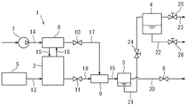
燃料電池システム1は、図2に示す構成に代えて図3に示す構成でも良い。図3に示す燃料電池システム1は、第1バルブ24と第2バルブ25と第3バルブ26を有する。第1バルブ24は、気液分離器3とタンク4を接続する管路21の途中に設けられる。第1バルブ24は、使用者によって開閉される。あるいは図示省略の制御装置によって開閉され、例えば燃料電池システム1の動作中に開かれ、燃料電池システム1の停止時に閉じられる。
The fuel cell system 1 may have the configuration shown in FIG. 3 instead of the configuration shown in FIG. The fuel cell system 1 shown in FIG. 3 has a
図3に示す第2バルブ25は、タンク4の上部に接続されたタンク用排ガス管23に設けられる。第2バルブ25は、使用者あるいは図示省略の制御装置によって開閉される。第3バルブ26は、タンク4の下部に接続された排水管22に設けられる。第3バルブ26は、使用者によって開かれる。
The
以上のように燃料電池システム1は、図3に示すように第1バルブ24、タンク用排ガス管23、第2バルブ25、排水管22、第3バルブ26を有する。第1バルブ24は、気液分離器3とタンク4を接続する管路21に設けられる。タンク用排ガス管23は、タンク4と接続されてタンク4内の気体を排出する。第2バルブ25は、タンク用排ガス管23に設けられ第1バルブ24と協働することでタンク4内の圧力を保持する。排水管22は、タンク4と接続されてタンク4内の水を排出する。第3バルブ26は、排水管22に設けられる。
As described above, the fuel cell system 1 includes the
したがって図3に示すように燃料電池2の動作中に第2バルブ25を閉じると、タンク4内の圧力が周辺気圧よりも上昇する。次に第1バルブ24を閉じるとタンク4内の圧力が保持される。第3バルブ26を開けることでタンク4内の圧力を利用してタンク4内の水が押出される。これにより水がタンク4から短時間で排出され得る。
Therefore, as shown in FIG. 3, when the
気液分離器3は、図2,3に示すように希釈器9と別個でも良いし、一体でも良い。気液分離器は、排出ガスから水を分離するものであれば他の構造でも良い。例えば気液分離器は、径の異なる部分を有し重力によって水が溜まるマフラー等、あるいは上方に屈曲し重力によって屈曲部分に水が溜まる管路等でも良い。 The gas-liquid separator 3 may be separate from the diluter 9 as shown in FIGS. The gas-liquid separator may have another structure as long as it separates water from the exhaust gas. For example, the gas-liquid separator may be a muffler or the like having portions with different diameters and collecting water by gravity, or a pipe line or the like bent upward and collecting water in the bent portions by gravity.
圧力調整機6は、図2,3に示すようにオリフィスでも良いし、状況に応じて気液分離器3内を所定圧力に設定し得る圧力調整弁、あるいは図示省略の制御装置によって所定の条件にて開閉される電磁弁などであっても良い。 The pressure regulator 6 may be an orifice as shown in FIGS. 2 and 3, or may be a predetermined condition by a pressure regulating valve that can set the gas-liquid separator 3 to a predetermined pressure according to the situation, or a control device (not shown) It may be a solenoid valve that is opened and closed at
燃料電池システム1は、産業車両30に設けられても良いし、家庭あるいは工場に設けられて家庭あるいは工場に電力を供給しても良い。燃料電池システム1は、フォークリフトに設けられても良いし、牽引車、自動搬送車、リフタ車などの他の産業車両、あるいは屋内を走行する車両に設けられても良い。
The fuel cell system 1 may be provided in the
タンク4は、図1に示すようにヘッドガード33に設けられても良いし、車体31の上部、例えばカウンタウェイト40の上に設けられても良い。
The
排ガス管20は、図2,3に示すように気液分離器3から延出する管でも良いし、気液分離器3に形成された開口部で形成され、該開口部(管)に圧力調整機6が設けられても良い。
The
排ガス管23は、図3に示すようにタンク4から延出する管でも良いし、タンク4に形成された開口部で形成され、該開口部(管)にバルブ12が設けられても良い。
The
1 燃料電池システム
2 燃料電池
3 気液分離器
4 タンク
5 水素タンク
6 圧力調整機
7 コンプレッサ
8 加湿器
9 希釈器
10 圧力調整弁
11 開閉弁
12 バルブ
13〜19,21 管路
20 排ガス管
22 排水管
23 タンク用排ガス管
24 第1バルブ
25 第2バルブ
26 第3バルブ
30 産業車両
31 車体
33 ヘッドガード
DESCRIPTION OF SYMBOLS 1
Claims (3)
燃料電池と、前記燃料電池と管路にて接続されかつ前記燃料電池から排出される排ガスに含まれる水を前記排ガスから分離する気液分離器と、前記気液分離器と管路にて接続されかつ前記気液分離器より上方に位置するタンクと、前記気液分離器に接続された排ガス管に設けられかつ前記排ガスの圧力を利用して前記気液分離器内の圧力を調整して前記気液分離器内の前記水を前記タンクへ供給する圧力調整機と、前記気液分離器と前記タンクを接続する前記管路に設けられる第1バルブと、前記タンクと接続されて前記タンク内の気体を排出するタンク用排ガス管と、前記タンク用排ガス管に設けられ前記第1バルブと協働することで前記タンク内の圧力を保持する第2バルブと、前記タンクと接続されて前記タンク内の水を排出する排水管と、前記排水管に設けられる第3バルブを有する燃料電池システム。 A fuel cell system,
A fuel cell, a gas-liquid separator connected to the fuel cell by a pipe line and separating water contained in the exhaust gas discharged from the fuel cell from the exhaust gas, and a pipe line connected to the gas-liquid separator And a tank located above the gas-liquid separator, an exhaust gas pipe connected to the gas-liquid separator, and adjusting the pressure in the gas-liquid separator using the pressure of the exhaust gas. A pressure regulator for supplying the water in the gas-liquid separator to the tank; a first valve provided in the conduit connecting the gas-liquid separator and the tank; and the tank connected to the tank An exhaust gas pipe for a tank that discharges the gas in the tank, a second valve that is provided in the exhaust gas pipe for the tank and holds the pressure in the tank by cooperating with the first valve, and connected to the tank, Drain to discharge water in the tank When a fuel cell system having a third valve provided in the drain pipe.
前記圧力調整機は、オリフィスである燃料電池システム。 The fuel cell system according to claim 1,
The pressure regulator is a fuel cell system that is an orifice.
車体と、前記車体の上方に位置する屋根を有し、
前記車体に前記燃料電池と前記気液分離器が設けられ、
前記屋根に前記タンクが設けられる燃料電池付産業車両。
An industrial vehicle with a fuel cell comprising the fuel cell system according to claim 1 or 2 ,
A vehicle body and a roof located above the vehicle body;
The fuel cell and the gas-liquid separator are provided on the vehicle body,
An industrial vehicle with a fuel cell, wherein the tank is provided on the roof.
Priority Applications (1)
| Application Number | Priority Date | Filing Date | Title |
|---|---|---|---|
| JP2012121506A JP5956832B2 (en) | 2012-05-29 | 2012-05-29 | Fuel cell system and industrial vehicle with fuel cell |
Applications Claiming Priority (1)
| Application Number | Priority Date | Filing Date | Title |
|---|---|---|---|
| JP2012121506A JP5956832B2 (en) | 2012-05-29 | 2012-05-29 | Fuel cell system and industrial vehicle with fuel cell |
Publications (2)
| Publication Number | Publication Date |
|---|---|
| JP2013247043A JP2013247043A (en) | 2013-12-09 |
| JP5956832B2 true JP5956832B2 (en) | 2016-07-27 |
Family
ID=49846646
Family Applications (1)
| Application Number | Title | Priority Date | Filing Date |
|---|---|---|---|
| JP2012121506A Expired - Fee Related JP5956832B2 (en) | 2012-05-29 | 2012-05-29 | Fuel cell system and industrial vehicle with fuel cell |
Country Status (1)
| Country | Link |
|---|---|
| JP (1) | JP5956832B2 (en) |
Families Citing this family (1)
| Publication number | Priority date | Publication date | Assignee | Title |
|---|---|---|---|---|
| JP7113309B2 (en) * | 2018-09-21 | 2022-08-05 | パナソニックIpマネジメント株式会社 | fuel cell system |
Family Cites Families (6)
| Publication number | Priority date | Publication date | Assignee | Title |
|---|---|---|---|---|
| JP4984543B2 (en) * | 2005-07-21 | 2012-07-25 | 日産自動車株式会社 | Fuel cell system |
| JP2007242328A (en) * | 2006-03-07 | 2007-09-20 | Nissan Motor Co Ltd | Fuel cell system |
| JP2008235203A (en) * | 2007-03-23 | 2008-10-02 | Toyota Industries Corp | Fuel cell system and method of discharging water produced in fuel cell system |
| JP2008300057A (en) * | 2007-05-29 | 2008-12-11 | Toyota Motor Corp | Fuel cell system |
| JP5005668B2 (en) * | 2008-12-22 | 2012-08-22 | 本田技研工業株式会社 | Fuel cell system |
| JP2012009215A (en) * | 2010-06-23 | 2012-01-12 | Honda Motor Co Ltd | Fuel cell system |
-
2012
- 2012-05-29 JP JP2012121506A patent/JP5956832B2/en not_active Expired - Fee Related
Also Published As
| Publication number | Publication date |
|---|---|
| JP2013247043A (en) | 2013-12-09 |
Similar Documents
| Publication | Publication Date | Title |
|---|---|---|
| JP5810753B2 (en) | Fuel cell vehicle | |
| JP5041272B2 (en) | Fuel cell system and moving body | |
| US10044052B2 (en) | Gas liquid separator and fuel cell system | |
| JP5743792B2 (en) | Fuel cell system | |
| US9895967B2 (en) | Piping member for fuel cell and fuel cell vehicle equipped therewith | |
| JP2016096018A (en) | Fuel cell system and discharge method of fluid in the system | |
| JP2005153852A (en) | Moving body | |
| JP2012163341A (en) | Hydrogen detection system | |
| JP6119662B2 (en) | Electric vehicle | |
| JP5767091B2 (en) | Moving body | |
| JP5093749B2 (en) | Fuel cell system | |
| JP2010218802A (en) | Fuel cell system | |
| JP2019069729A (en) | Fuel cell vehicle and method of controlling fuel cell vehicle | |
| JP2008235205A (en) | Fuel cell system | |
| JP5082311B2 (en) | Fuel cell system | |
| JP5956832B2 (en) | Fuel cell system and industrial vehicle with fuel cell | |
| JP2010218803A (en) | Fuel cell system | |
| JP5007931B2 (en) | Fuel tank support device | |
| JP5316431B2 (en) | Fuel cell system | |
| WO2010070881A1 (en) | Fuel cell system and method for controlling valve opening operation when the fuel cell system is activated | |
| JP2010278130A (en) | Cooling device for power device, and fuel cell system | |
| JP2007311039A (en) | Fuel cell system, and mobile unit | |
| JP4682564B2 (en) | Gas detection system and gas detection method | |
| JP6059972B2 (en) | Fuel cell system | |
| JP2008196596A (en) | Solenoid valve |
Legal Events
| Date | Code | Title | Description |
|---|---|---|---|
| A711 | Notification of change in applicant |
Free format text: JAPANESE INTERMEDIATE CODE: A711 Effective date: 20140618 |
|
| A521 | Request for written amendment filed |
Free format text: JAPANESE INTERMEDIATE CODE: A821 Effective date: 20140618 |
|
| A621 | Written request for application examination |
Free format text: JAPANESE INTERMEDIATE CODE: A621 Effective date: 20150408 |
|
| A131 | Notification of reasons for refusal |
Free format text: JAPANESE INTERMEDIATE CODE: A131 Effective date: 20160308 |
|
| A521 | Request for written amendment filed |
Free format text: JAPANESE INTERMEDIATE CODE: A523 Effective date: 20160426 |
|
| TRDD | Decision of grant or rejection written | ||
| A01 | Written decision to grant a patent or to grant a registration (utility model) |
Free format text: JAPANESE INTERMEDIATE CODE: A01 Effective date: 20160614 |
|
| A61 | First payment of annual fees (during grant procedure) |
Free format text: JAPANESE INTERMEDIATE CODE: A61 Effective date: 20160617 |
|
| R150 | Certificate of patent or registration of utility model |
Ref document number: 5956832 Country of ref document: JP Free format text: JAPANESE INTERMEDIATE CODE: R150 |
|
| R250 | Receipt of annual fees |
Free format text: JAPANESE INTERMEDIATE CODE: R250 |
|
| R250 | Receipt of annual fees |
Free format text: JAPANESE INTERMEDIATE CODE: R250 |
|
| R250 | Receipt of annual fees |
Free format text: JAPANESE INTERMEDIATE CODE: R250 |
|
| R250 | Receipt of annual fees |
Free format text: JAPANESE INTERMEDIATE CODE: R250 |
|
| LAPS | Cancellation because of no payment of annual fees |