JP5956210B2 - Start-up method of pressurized flow furnace system - Google Patents
Start-up method of pressurized flow furnace system Download PDFInfo
- Publication number
- JP5956210B2 JP5956210B2 JP2012069487A JP2012069487A JP5956210B2 JP 5956210 B2 JP5956210 B2 JP 5956210B2 JP 2012069487 A JP2012069487 A JP 2012069487A JP 2012069487 A JP2012069487 A JP 2012069487A JP 5956210 B2 JP5956210 B2 JP 5956210B2
- Authority
- JP
- Japan
- Prior art keywords
- pressurized fluidized
- fluidized furnace
- supplied
- combustion
- pressurized
- Prior art date
- Legal status (The legal status is an assumption and is not a legal conclusion. Google has not performed a legal analysis and makes no representation as to the accuracy of the status listed.)
- Active
Links
- 238000000034 method Methods 0.000 title claims description 29
- 238000002485 combustion reaction Methods 0.000 claims description 188
- 239000007858 starting material Substances 0.000 claims description 62
- 239000004576 sand Substances 0.000 claims description 54
- 239000000446 fuel Substances 0.000 claims description 50
- XLYOFNOQVPJJNP-UHFFFAOYSA-N water Substances O XLYOFNOQVPJJNP-UHFFFAOYSA-N 0.000 claims description 32
- 238000010438 heat treatment Methods 0.000 claims description 15
- 239000000126 substance Substances 0.000 claims description 7
- 239000007789 gas Substances 0.000 description 69
- 239000000779 smoke Substances 0.000 description 28
- 230000002265 prevention Effects 0.000 description 22
- 239000000428 dust Substances 0.000 description 17
- HEMHJVSKTPXQMS-UHFFFAOYSA-M Sodium hydroxide Chemical compound [OH-].[Na+] HEMHJVSKTPXQMS-UHFFFAOYSA-M 0.000 description 15
- UGFAIRIUMAVXCW-UHFFFAOYSA-N Carbon monoxide Chemical compound [O+]#[C-] UGFAIRIUMAVXCW-UHFFFAOYSA-N 0.000 description 13
- 239000003546 flue gas Substances 0.000 description 12
- 230000000694 effects Effects 0.000 description 9
- 239000012535 impurity Substances 0.000 description 7
- 239000012530 fluid Substances 0.000 description 6
- 230000004913 activation Effects 0.000 description 5
- 238000005336 cracking Methods 0.000 description 5
- 238000007599 discharging Methods 0.000 description 5
- 235000011121 sodium hydroxide Nutrition 0.000 description 5
- 239000002699 waste material Substances 0.000 description 5
- 239000000567 combustion gas Substances 0.000 description 4
- 239000000295 fuel oil Substances 0.000 description 4
- 239000000463 material Substances 0.000 description 4
- 239000002245 particle Substances 0.000 description 4
- 239000010801 sewage sludge Substances 0.000 description 4
- 239000002028 Biomass Substances 0.000 description 3
- 238000005507 spraying Methods 0.000 description 3
- 238000001514 detection method Methods 0.000 description 2
- 238000009434 installation Methods 0.000 description 2
- 238000009287 sand filtration Methods 0.000 description 2
- 239000007921 spray Substances 0.000 description 2
- 238000009835 boiling Methods 0.000 description 1
- 229910002091 carbon monoxide Inorganic materials 0.000 description 1
- 239000000919 ceramic Substances 0.000 description 1
- 230000000052 comparative effect Effects 0.000 description 1
- 238000007796 conventional method Methods 0.000 description 1
- 238000001816 cooling Methods 0.000 description 1
- 239000000498 cooling water Substances 0.000 description 1
- 230000003247 decreasing effect Effects 0.000 description 1
- 239000006185 dispersion Substances 0.000 description 1
- 239000003921 oil Substances 0.000 description 1
- 230000035939 shock Effects 0.000 description 1
- 239000010802 sludge Substances 0.000 description 1
- 239000007787 solid Substances 0.000 description 1
- 239000008400 supply water Substances 0.000 description 1
- 238000011144 upstream manufacturing Methods 0.000 description 1
Images


Classifications
-
- F—MECHANICAL ENGINEERING; LIGHTING; HEATING; WEAPONS; BLASTING
- F23—COMBUSTION APPARATUS; COMBUSTION PROCESSES
- F23G—CREMATION FURNACES; CONSUMING WASTE PRODUCTS BY COMBUSTION
- F23G5/00—Incineration of waste; Incinerator constructions; Details, accessories or control therefor
- F23G5/30—Incineration of waste; Incinerator constructions; Details, accessories or control therefor having a fluidised bed
-
- F—MECHANICAL ENGINEERING; LIGHTING; HEATING; WEAPONS; BLASTING
- F23—COMBUSTION APPARATUS; COMBUSTION PROCESSES
- F23C—METHODS OR APPARATUS FOR COMBUSTION USING FLUID FUEL OR SOLID FUEL SUSPENDED IN A CARRIER GAS OR AIR
- F23C10/00—Fluidised bed combustion apparatus
- F23C10/16—Fluidised bed combustion apparatus specially adapted for operation at superatmospheric pressures, e.g. by the arrangement of the combustion chamber and its auxiliary systems inside a pressure vessel
-
- F—MECHANICAL ENGINEERING; LIGHTING; HEATING; WEAPONS; BLASTING
- F23—COMBUSTION APPARATUS; COMBUSTION PROCESSES
- F23C—METHODS OR APPARATUS FOR COMBUSTION USING FLUID FUEL OR SOLID FUEL SUSPENDED IN A CARRIER GAS OR AIR
- F23C10/00—Fluidised bed combustion apparatus
- F23C10/18—Details; Accessories
-
- F—MECHANICAL ENGINEERING; LIGHTING; HEATING; WEAPONS; BLASTING
- F23—COMBUSTION APPARATUS; COMBUSTION PROCESSES
- F23G—CREMATION FURNACES; CONSUMING WASTE PRODUCTS BY COMBUSTION
- F23G5/00—Incineration of waste; Incinerator constructions; Details, accessories or control therefor
- F23G5/44—Details; Accessories
-
- F—MECHANICAL ENGINEERING; LIGHTING; HEATING; WEAPONS; BLASTING
- F23—COMBUSTION APPARATUS; COMBUSTION PROCESSES
- F23G—CREMATION FURNACES; CONSUMING WASTE PRODUCTS BY COMBUSTION
- F23G5/00—Incineration of waste; Incinerator constructions; Details, accessories or control therefor
- F23G5/50—Control or safety arrangements
-
- F—MECHANICAL ENGINEERING; LIGHTING; HEATING; WEAPONS; BLASTING
- F23—COMBUSTION APPARATUS; COMBUSTION PROCESSES
- F23L—SUPPLYING AIR OR NON-COMBUSTIBLE LIQUIDS OR GASES TO COMBUSTION APPARATUS IN GENERAL ; VALVES OR DAMPERS SPECIALLY ADAPTED FOR CONTROLLING AIR SUPPLY OR DRAUGHT IN COMBUSTION APPARATUS; INDUCING DRAUGHT IN COMBUSTION APPARATUS; TOPS FOR CHIMNEYS OR VENTILATING SHAFTS; TERMINALS FOR FLUES
- F23L5/00—Blast-producing apparatus before the fire
-
- F—MECHANICAL ENGINEERING; LIGHTING; HEATING; WEAPONS; BLASTING
- F23—COMBUSTION APPARATUS; COMBUSTION PROCESSES
- F23C—METHODS OR APPARATUS FOR COMBUSTION USING FLUID FUEL OR SOLID FUEL SUSPENDED IN A CARRIER GAS OR AIR
- F23C2900/00—Special features of, or arrangements for combustion apparatus using fluid fuels or solid fuels suspended in air; Combustion processes therefor
- F23C2900/10001—Use of special materials for the fluidized bed
-
- F—MECHANICAL ENGINEERING; LIGHTING; HEATING; WEAPONS; BLASTING
- F23—COMBUSTION APPARATUS; COMBUSTION PROCESSES
- F23C—METHODS OR APPARATUS FOR COMBUSTION USING FLUID FUEL OR SOLID FUEL SUSPENDED IN A CARRIER GAS OR AIR
- F23C2900/00—Special features of, or arrangements for combustion apparatus using fluid fuels or solid fuels suspended in air; Combustion processes therefor
- F23C2900/10002—Treatment devices for the fluidizing gas, e.g. cooling, filtering
-
- F—MECHANICAL ENGINEERING; LIGHTING; HEATING; WEAPONS; BLASTING
- F23—COMBUSTION APPARATUS; COMBUSTION PROCESSES
- F23C—METHODS OR APPARATUS FOR COMBUSTION USING FLUID FUEL OR SOLID FUEL SUSPENDED IN A CARRIER GAS OR AIR
- F23C2900/00—Special features of, or arrangements for combustion apparatus using fluid fuels or solid fuels suspended in air; Combustion processes therefor
- F23C2900/10006—Pressurized fluidized bed combustors
-
- F—MECHANICAL ENGINEERING; LIGHTING; HEATING; WEAPONS; BLASTING
- F23—COMBUSTION APPARATUS; COMBUSTION PROCESSES
- F23C—METHODS OR APPARATUS FOR COMBUSTION USING FLUID FUEL OR SOLID FUEL SUSPENDED IN A CARRIER GAS OR AIR
- F23C2900/00—Special features of, or arrangements for combustion apparatus using fluid fuels or solid fuels suspended in air; Combustion processes therefor
- F23C2900/99006—Arrangements for starting combustion
Description
本発明は、下水汚泥、バイオマス、都市ゴミ等の被処理物を燃焼する加圧流動炉システムの起動方法に関するものであり、より詳細には、加圧流動炉の底部に堆積した流動砂の割れを防止して流動砂の交換頻度を低減し、流動砂の加熱に使用する補助燃料の消費を低減する加圧流動炉システムの起動方法に関するものである。 The present invention relates to a method for starting a pressurized fluidized furnace system for burning an object to be treated such as sewage sludge, biomass, municipal waste, and more specifically, cracking of fluidized sand deposited at the bottom of the pressurized fluidized furnace. It is related with the starting method of the pressurization fluidized-furnace system which reduces the consumption frequency of the auxiliary | assistant fuel which is used for heating the fluidized sand, reducing the frequency of fluidized sand replacement.
従来、下水汚泥、バイオマス、都市ゴミ等の被処理物を燃焼し、焼却炉から排出される燃焼排ガスの持つエネルギーを有効に取り出すことに着目した焼却設備として、加圧流動炉システムが知られている。加圧流動炉システムは、被処理物を燃焼させる加圧流動炉と、加圧流動炉から排出される燃焼排ガスによって回動されるタービンとタービンの回動に伴って回動され圧縮空気を供給するコンプレッサーを内装する過給機を有することを特徴とするシステムである。加圧流動動炉システムでは、被処理物を燃焼させた際に生じる燃焼排ガスによって過給機のタービンを駆動し、コンプレッサーから排出される圧縮空気によって被処理物の必要燃焼空気全量を供給する自立運転が可能となる。自立運転が可能となることで、従来、必要であった流動ブロワおよび誘引ファンが不要となり、ランニングコストが低減することが知られている。
この加圧流動炉システムの起動方法として、加圧流動炉の底部に充填した流動砂を約550℃に加熱した後に、加圧流動炉の上部に配置されたウォータガンから流動砂に向けて砂ろ過水を噴霧し、加圧流動炉で発生する燃焼排ガスを増加させ、加圧流動炉に燃焼空気を供給する方法が提案されている(非特許文献1、特許文献1、2参照)。
Conventionally, a pressurized fluidized furnace system has been known as an incineration facility that focuses on effectively taking out the energy of combustion exhaust gas discharged from an incinerator by burning an object to be treated such as sewage sludge, biomass, and municipal waste. Yes. The pressurized fluidized furnace system is a pressurized fluidized furnace that combusts a workpiece, a turbine that is rotated by combustion exhaust gas discharged from the pressurized fluidized furnace, and is rotated as the turbine rotates to supply compressed air. It is the system characterized by having the supercharger which mounts the compressor which carries out. In a pressurized flow reactor system, the turbine of the turbocharger is driven by combustion exhaust gas generated when the workpiece is burned, and the required combustion air for the workpiece is supplied by compressed air discharged from the compressor. Driving is possible. It has been known that the self-sustained operation can eliminate the need for a fluid blower and an attracting fan, which have been conventionally required, and reduce the running cost.
As a starting method of this pressurized fluidized furnace system, after the fluidized sand filled in the bottom of the pressurized fluidized furnace is heated to about 550 ° C., the sand is directed toward the fluidized sand from the water gun disposed at the top of the pressurized fluidized furnace. There has been proposed a method of spraying filtered water, increasing combustion exhaust gas generated in a pressurized fluidized furnace, and supplying combustion air to the pressurized fluidized furnace (see Non-Patent Document 1, Patent Documents 1 and 2).
しかしながら、従来の加圧流動炉システムの起動方法は、加圧流動炉の昇温に伴い約550℃に加熱された流動砂と炉内に噴霧された常温の水が接触することで、流動砂に割れが発生して小粒となるために、流動砂の消費量が増えるという虞があった。
また、非特許文献1、特許文献1、2に記載された加圧流動炉システムの起動方法は、自立運転完了まで排ガス温度および排ガス流量の維持のために重油、都市ガス等の補助燃料を使用する必要があり、その消費が多いという虞があった。
However, the conventional method for starting up the pressurized fluidized furnace system is that the fluidized sand heated to about 550 ° C. with the temperature rise of the pressurized fluidized furnace comes into contact with the normal temperature water sprayed in the furnace, so that the fluidized sand There is a concern that the consumption of fluidized sand may increase because cracks occur in the sand.
In addition, the startup method of the pressurized fluidized furnace system described in Non-Patent Document 1, Patent Documents 1 and 2 uses auxiliary fuel such as heavy oil and city gas to maintain the exhaust gas temperature and the exhaust gas flow rate until the self-sustained operation is completed. There is a risk that the consumption is high.
そこで、本発明の主たる課題は、かかる問題点を解消することにある。 Therefore, the main problem of the present invention is to eliminate such problems.
上記課題を解決した本発明及び作用効果は、次のとおりである。
第1発明は、底部に流動砂を充填して含水有機物質を有する被処理物を燃焼させる加圧流動炉と、該加圧流動炉から排出される燃焼排ガスによって回動するタービンとタービンの回動に伴って回動し圧縮空気を加圧流動炉に燃焼空気として供給するコンプレッサーを内装する過給機と、前記加圧流動炉に燃焼空気を供給する起動用送風機と、前記加圧流動炉内を加熱する加熱手段とを備えた加圧流動炉システムの起動方法であって、
前記起動用送風機を駆動して燃焼空気を加圧流動炉に供給し、
前記加熱手段により前記流動砂を加熱して加圧流動炉のフリーボード部の温度を昇温し、
前記フリーボード部の温度が750〜900℃に昇温した後に、前記加圧流動炉に被処理物を供給して燃焼排ガスを増加させ、
前記過給機のタービンの供給口の燃焼排ガスの温度が500〜650℃に達した後に、前記タービンの供給口とタービンの下流側を接続する流路に設けられたダンパを閉方向に駆動し、前記燃焼排ガスによって前記過給機を駆動させて燃焼空気を加圧流動炉に供給した後に、前記起動用送風機を停止させることを特徴とする。
The present invention and effects obtained by solving the above problems are as follows.
According to a first aspect of the present invention, there is provided a pressurized fluidizing furnace for burning a workpiece having a water-containing organic substance by filling fluidized sand at the bottom, a turbine rotated by combustion exhaust gas discharged from the pressurized fluidized furnace, and a turbine rotation. A supercharger that includes a compressor that rotates with movement and supplies compressed air as combustion air to the pressurized fluidized furnace, a starter fan that supplies combustion air to the pressurized fluidized furnace, and the pressurized fluidized furnace A method of starting a pressurized fluidized furnace system comprising heating means for heating the inside,
Drive the starter blower to supply combustion air to the pressurized fluidized furnace,
The fluidized sand is heated by the heating means to raise the temperature of the freeboard part of the pressurized fluidized furnace,
After the temperature of the free board part is raised to 750 to 900 ° C., the object to be treated is supplied to the pressurized fluidized furnace to increase the combustion exhaust gas,
After the temperature of the combustion exhaust gas at the supply port of the turbine of the supercharger reaches 500 to 650 ° C., a damper provided in a flow path connecting the supply port of the turbine and the downstream side of the turbine is driven in the closing direction. Then, after the supercharger is driven by the combustion exhaust gas and the combustion air is supplied to the pressurized fluidized furnace, the starter blower is stopped.
(作用効果)
加圧流動炉のフリーボード部の温度が750〜900℃に昇温した後に、過給機のタービンの供給口の燃焼排ガスの温度が500〜650℃に達した後に、前記タービンの供給口とタービンの下流側を接続する流路に設けられたダンパを閉方向に駆動し、加圧流動炉に被処理物を供給して燃焼排ガスを増加させ、燃焼排ガスによって過給機を駆動させて燃焼空気を加圧流動炉に供給するので、ヒートショックによる流動砂の割れを抑制し、流動砂の交換頻度を低減することができる。また、被処理物に内在された有機物質を燃焼させることによって加圧流動炉に要求される重油、都市ガス等の補助燃料の消費を低減することもできる。さらに、加圧流動炉の急激な変動を抑制することができる。
(Function and effect)
After the temperature of the freeboard portion of the pressurized fluidized furnace is raised to 750 to 900 ° C., the temperature of the combustion exhaust gas at the supply port of the turbocharger turbine reaches 500 to 650 ° C., and The damper provided in the flow path connecting the downstream side of the turbine is driven in the closing direction, the material to be treated is supplied to the pressurized flow furnace to increase the combustion exhaust gas, and the supercharger is driven by the combustion exhaust gas for combustion Since air is supplied to the pressurized fluidized furnace, cracking of fluidized sand due to heat shock can be suppressed, and the frequency of fluidized sand replacement can be reduced. In addition, the consumption of auxiliary fuel such as heavy oil and city gas required for the pressurized fluidized furnace can be reduced by burning the organic substance contained in the object to be processed. Furthermore, rapid fluctuations in the pressurized fluidized furnace can be suppressed.
第2発明は、第1発明の構成において、前記加圧流動炉に被処理物の燃焼に使用される燃焼空気よりも多くの燃焼空気を、前記起動用送風機と過給機によって供給することを特徴とする。 According to a second aspect of the present invention, in the configuration of the first aspect of the present invention, more combustion air is supplied to the pressurized fluidized furnace than the combustion air used for combustion of the workpiece by the starter blower and the supercharger. Features.
(作用効果)
加圧流動炉に被処理物の燃焼に使用される燃焼空気よりも多くの燃焼空気を、起動用送風機と過給機によって供給するので、被処理物が完全燃焼し一酸化炭素等の有害物質の発生を抑制することができる。
(Function and effect)
Because more combustion air is supplied to the pressurized fluidized furnace than the combustion air used for combustion of the object to be processed by the starter and supercharger, the object to be processed is completely burned and harmful substances such as carbon monoxide Can be suppressed.
第3発明は、第1又は2発明の構成において、前記加圧流動炉の炉内圧力が所定の時間一定となった場合に、前記被処理物の供給を開始することを特徴とする。 A third invention is characterized in that, in the configuration of the first or second invention, the supply of the workpiece is started when the pressure in the pressurized fluidized furnace becomes constant for a predetermined time.
(作用効果)
加圧流動炉内の圧力が所定の時間一定となった場合に、被処理物の供給を開始するので、ウォータガンなどで燃焼排ガスを増量させることなく過給機の運転をより好適に開始することができる。
(Function and effect)
Since the supply of the object to be processed is started when the pressure in the pressurized fluidized furnace becomes constant for a predetermined time, the operation of the supercharger is more preferably started without increasing the amount of combustion exhaust gas with a water gun or the like. be able to.
第4発明は、第1〜3発明の構成において、前記タービンに供給される燃焼排ガスが所定の温度となった後に、前記起動用送風機の吐出側から前記コンプレッサー吸込側への流路から分岐して前記コンプレッサー吐出側の流路との間に配置されたバイパス流路を閉塞し、前記起動用送風機から空気流路を介してコンプレッサーの供給口に燃焼空気を供給することを特徴とする。 According to a fourth invention, in the configuration of the first to third inventions, after the flue gas supplied to the turbine reaches a predetermined temperature, it branches from the flow path from the discharge side of the starter blower to the compressor suction side. The bypass flow path disposed between the compressor discharge side flow path is closed, and combustion air is supplied from the starter blower to the compressor supply port via the air flow path.
(作用効果)
過給機の供給口における燃焼排ガスが所定の温度となった後、起動用送風機から過給機を介して加圧流動炉へ燃焼空気の供給を開始するので、ウォータガンなどで燃焼排ガスを増量させることなく過給機の運転を開始することができる。
(Function and effect)
After the combustion exhaust gas at the supply port of the turbocharger reaches a predetermined temperature, supply of combustion air from the starter blower to the pressurized fluidized furnace via the turbocharger is started. The operation of the supercharger can be started without causing it.
第5発明は、第1〜4発明の構成において、前記被処理物を一定の割合で増加させながら加圧流動炉に供給することを特徴とする。 A fifth invention is characterized in that, in the configuration of the first to fourth inventions, the workpiece is supplied to the pressurized fluidized furnace while being increased at a constant rate.
(作用効果)
被処理物を一定の割合で増加させながら加圧流動炉に供給するので、加圧流動炉の温度の変動を抑制でき、安定して過給機の自立運転に移行することができる。
(Function and effect)
Since the object to be treated is supplied to the pressurized fluidized furnace while being increased at a constant rate, fluctuations in the temperature of the pressurized fluidized furnace can be suppressed, and stable operation of the supercharger can be performed.
第6発明は、第1〜4発明の構成において、前記被処理物を階段的に増加させながら加圧流動炉に供給することを特徴とする。 A sixth invention is characterized in that, in the configuration of the first to fourth inventions, the workpieces are supplied to the pressurized fluidized furnace while being increased stepwise.
(作用効果)
被処理物を階段的に増加させながら加圧流動炉に供給するので、被処理物の供給方法を簡易に行うことができ、被処理物の供給量の変動を抑制することができる。また、加圧流動炉の温度の変動を抑制でき、安定して過給機の自立運転に移行することができる。
(Function and effect)
Since the object to be processed is supplied to the pressurized fluidized furnace while being increased stepwise, the method for supplying the object to be processed can be easily performed, and fluctuations in the supply amount of the object to be processed can be suppressed. Moreover, the fluctuation | variation of the temperature of a pressurized flow furnace can be suppressed, and it can transfer to the self-sustained operation of a supercharger stably.
第7発明は、第6発明の構成において、前記加圧流動炉の定格処理量の20〜30質量%の前記被処理物を供給し、
前記過給機から供給される燃焼空気が定格容量の50vol%以上になった後に、定格処理量の40〜50質量%の前記被処理物を供給することを特徴とする。
In a seventh aspect of the present invention, in the configuration of the sixth aspect of the present invention, the object to be processed is supplied in an amount of 20 to 30% by mass of the rated throughput of the pressurized fluidized furnace,
After the combustion air supplied from the supercharger has reached 50 vol% or more of the rated capacity, 40 to 50 mass% of the workpiece to be processed is supplied.
(作用効果)
加圧流動炉の定格処理量の20〜30質量%の被処理物を加圧流動炉に供給しているので、被処理物の供給開始時に発生する流動砂の温度の降温を防止することができる。
また、過給機から供給される燃焼空気を定格容量の50vol%以上とした後に、定格処理量の40〜50質量%の被処理物を加圧流動炉に供給するので、加圧流動炉の温度の変動をより抑制でき、短時間で過給機の自立運転に移行することができる。
(Function and effect)
Since 20 to 30% by mass of the treatment amount of the rated flow rate of the pressurized fluidized furnace is supplied to the pressurized fluidized furnace, it is possible to prevent the temperature of the fluid sand generated at the start of the supply of the treated material from falling. it can.
In addition, after the combustion air supplied from the supercharger is set to 50 vol% or more of the rated capacity, an object to be processed of 40 to 50% by mass of the rated throughput is supplied to the pressurized fluidized furnace. Temperature fluctuations can be further suppressed, and the self-sustained operation of the supercharger can be shifted in a short time.
第8発明は、第1〜7発明の構成において、前記加圧流動炉は、加熱手段として底部に充填した流動砂を加熱する始動用バーナーと補助燃料燃焼装置とを備え、
前記流動砂を前記始動用バーナーによって650〜700℃に昇温した後に、前記流動砂を前記補助燃料燃焼装置によって750〜850℃に昇温させることを特徴とする。
According to an eighth aspect of the present invention, in the configuration of the first to seventh aspects, the pressurized fluidized furnace includes a starter burner for heating the fluidized sand filled in the bottom portion as a heating means and an auxiliary fuel combustion device,
After the temperature of the fluidized sand is raised to 650 to 700 ° C. by the starter burner, the temperature of the fluidized sand is raised to 750 to 850 ° C. by the auxiliary fuel combustion device.
(作用効果)
始動用バーナーで加圧流動炉の流動砂の表面部を加熱した後、補助燃料燃焼装置で流動砂の中心部を加熱するので、流動砂を効率良く昇温でき、補助燃料の消費を抑制することができる。
(Function and effect)
After heating the surface of the fluidized sand of the pressurized fluidized furnace with the starter burner, the center of the fluidized sand is heated with the auxiliary fuel combustion device, so the temperature of the fluidized sand can be increased efficiently and the consumption of auxiliary fuel is suppressed. be able to.
以上の発明によれば、過給機の自立運転前から被処理物を投入することが可能となるので低コストで流動砂の割れを抑制することが可能となる。 According to the above invention, since it becomes possible to throw in a to-be-processed object from before a self-sustained operation of a supercharger, it becomes possible to control cracking of fluidized sand at low cost.
以下、本発明の本実施形態について添付図面を参照しつつ詳説する。なお、理解を容易にするため、便宜的に方向を示して説明しているが、これらにより構成が限定されるものではない。 Hereinafter, this embodiment of the present invention will be described in detail with reference to the accompanying drawings. In addition, in order to make an understanding easy, although it showed and demonstrated the direction for convenience, the structure is not limited by these.
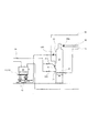
加圧流動炉システム1は、図1に示すように、汚泥等の被処理物を貯留する貯留装置10と、貯留装置10から供給された被処理物を燃焼する加圧流動炉20と、加圧流動炉20から排出された燃焼排ガスによって加圧流動炉20に供給する燃焼空気を加熱する空気予熱器40と、燃焼排ガス中の粉塵等を除去する集塵機50と、燃焼排ガスによって駆動され加圧流動炉20に燃焼空気を供給する過給機60と、過給機60から排出された燃焼排ガスによって排煙処理塔80に供給する白煙防止用空気を加熱する白煙防止用予熱器70と、燃焼排ガス内の不純物を除去する排煙処理塔80を備えている。
As shown in FIG. 1, the pressurized fluidized furnace system 1 includes a
(貯留装置)
貯留装置10に貯留される被処理物は、主に含水率を70〜85%質量に脱水処理された下水汚泥であり、被処理物には、燃焼可能な有機物が含有されている。なお、被処理物は、含水有機物であれば下水汚泥に制限されることはなく、バイオマス、都市ゴミ等であっても良い。
(Storage device)
The object to be processed stored in the
貯留装置10の下部には、所定量の被処理物を加圧流動炉20に供給する定量フィーダ11が配置され、定量フィーダ11の下流側には、被処理物を加圧流動炉20に圧送する投入ポンプ12が設けられている。なお、投入ポンプ12としては、一軸ネジ式ポンプ、ピストンポンプ等が使用できる。
A fixed amount feeder 11 for supplying a predetermined amount of the object to be processed to the pressurized
(加圧流動炉)
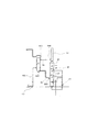
加圧流動炉20は、流動媒体として所定の粒径を有する、流動砂等の固体粒子が炉内の下部に充填された燃焼炉であり、炉内に供給される燃焼空気によって流動層(以下、砂層という。)の流動状態を維持しつつ、外部から供給される被処理物および必要に応じて供給される補助燃料を燃焼させるものである。加圧流動炉20は、加熱手段として補助燃料燃焼装置21、始動用バーナー22の少なくとも1つを備えている。 図1、図2に示すように、一側の側壁の下部には、加圧流動炉20の内部に充填された粒径約400〜600μmの流動砂を加熱する補助燃料燃焼装置21が配置され、補助燃料燃焼装置21の上側近傍の部位には、始動時に流動砂を加熱する始動用バーナー22が配置され、始動用バーナー22の上側の部位には、被処理物の供給口13Bが設けられている。また、加圧流動炉20の上部には、燃焼排ガスを冷却するためのウォータガン23が配置され、必要に応じ冷却水を炉内に噴霧することができる。
(Pressurized flow furnace)
The pressurized
補助燃料燃焼装置21は、加圧流動炉20に充填された流動砂を加熱するために、燃焼空気供給管(分散管)24の上側に配置されている。また、補助燃料燃焼装置21は、燃焼空気供給管24と同様に複数本が並列に配置されている。補助燃料燃焼装置21は、炉外に設置された補助燃料供給装置29から都市ガスや重油等の補助燃料が供給されている。なお、補助燃料燃焼装置21として、ガスガンやオイルガンを使用することもできる。
The auxiliary
始動用バーナー22は、始動時に流動砂の上面を加熱するために、加圧流動炉20の中心部に向かって立下がり傾斜して配置されている。なお、補助燃料燃焼装置21と同様に、始動用バーナー22には、炉外の補助燃料供給装置29から補助燃料が供給されている。また、始動用バーナー22の燃焼空気は、配管96を介して起動用送風機65の発生した送風空気が使用される。
The starting
加圧流動炉20の他側の側壁の下部には、加圧流動炉20の内部に燃焼空気を供給する燃焼空気供給管24が配置されている。加圧流動炉20の上部の細径化された側壁には、補助燃料、被処理物等の燃焼によって発生した燃焼ガスや、砂ろ過水、被処理物に内在する水等が加熱されることで生じた水蒸気などを炉外に排出する排出口90Aが形成されている。なお、本発明では、燃焼ガス、又は燃焼ガスと水蒸気が混合したガスを燃焼排ガスという。
A combustion
燃焼空気供給管24は、補助燃料燃焼装置21から供給された補助燃料に均等に燃焼空気を供給するために、補助燃料燃焼装置21の下側に配置される。
加圧流動炉20の側壁には、炉内温度を測定するための温度センサ(図示省略)が高さ方向にそって所定間隔で複数設置されている。設置個所は、砂層およびフリーボード部であり、それぞれ2箇所から3箇所、計4〜6箇所となる。温度センサとしては、熱電対等を使用することが出来る。ここで、フリーボード部とは、加圧流動層燃焼炉11の内部において砂層の上層部を指す。これら温度センサは、それぞれの設置位置における炉内温度を示す電気信号を制御装置(図示省略)に出力する。
The combustion
A plurality of temperature sensors (not shown) for measuring the in-furnace temperature are installed on the side wall of the
(空気予熱器)
空気予熱器40は、加圧流動炉20の後段に設置され、加圧流動炉20から排出された燃焼排ガスと燃焼空気とを間接的に熱交換することにより、燃焼空気を所定の温度まで昇温する機器である。
空気予熱器40は、図1、図3に示すように、一側の側壁の上部には、加圧流動炉20からの燃焼排ガスの供給口90Bが形成され、供給口90Bの下側近傍部位には、燃焼空気を空気予熱器40から排出する排出口91Aが形成されている。また、燃焼排ガスの供給口90Bは、配管90を介して加圧流動炉20の排出口90Aに接続され、燃焼空気の排出口91Aは、配管91を介して加圧流動炉20の燃焼空気供給管24の後部に接続されている。
(Air preheater)
The
As shown in FIGS. 1 and 3, the
空気予熱器40の他側の下部には、燃焼排ガスを空気予熱器40から排出する排出口92Aが形成され、排出口92Aの上側近傍の部位には、燃焼空気を機器内に供給する供給口95Bが形成されている。空気予熱器としては、シェルアンドチューブ式熱交換器が好ましい。
A
(集塵機)
集塵機50は、空気予熱器40の後段に設けられており、空気予熱器40から送出される燃焼排ガスに含まれるダスト、細粒化された流動砂等の不純物を除去する機器である。
集塵機50に内装されるフィルタとしては、例えばセラミックフィルタやバグフィルタを用いることができ、集塵機50は、一側の側壁の下部には、燃焼排ガスを機器内に供給する供給口92Bが形成され、上部には、不純物等が取除かれた清浄な燃焼排ガスを機器外に排出する排出口93Aが形成されている。また、燃焼排ガスの供給口92Bは、配管92を介して空気予熱器40の燃焼排ガスの排出口92Aに接続されている。
(Dust collector)
The
As a filter installed in the
集塵機50内には、下部に形成された供給口92Bと上部に形成された排出口93Aの上下方向に間の部位にバフィルタ(図示省略)が内装されている。フィルタで取除かれた燃焼排ガス中の不純物等は、集塵機50内の底部に一時的に貯留された後、定期的に外部に排出される。
Inside the
(過給機)
過給機60は、集塵機50の後段に設けられており、集塵機50から送出される燃焼排ガスによって回動されるタービン61と、タービン61の回動を伝達する軸63と、軸63によって回動を伝達されることによって圧縮空気を生成するコンプレッサー62とから構成されている。生成された圧縮空気は、燃焼空気として加圧流動炉20へ供給される。
過給機60のタービン61側の側壁の下部(軸63と直交する部位)には、集塵機50によって不純物が除去された清浄な燃焼排ガスを機器内に供給する供給口93Bが形成され、タービン61側の側壁の下流側(軸63と平行する部位)には、燃焼排ガスを機器外に排出する排出口97Aが形成されている。また、燃焼排ガスの供給口93Bは、配管93を介して集塵機50の排出口93Aに接続されている。なお、配管93には燃焼排ガス温度を測定する温度測定手段93Dが設置される。
(Supercharger)
The
A
過給機60のコンプレッサー62側の側壁の上流側(軸63と平行する部位)には、空気を機器内に吸気する供給口67Bが形成され、タービン61側の側壁の上側(軸63と直交する部位)には、吸気された空気を0.05〜0.3MPaに昇圧した圧縮空気を機器外に排出する排出口94Aが形成されている。また、外気の供給口67Bは、配管16、67を介して、空気を吸気する。また、配管66,67を介して始動時に加圧流動炉20に燃焼空気を供給する起動用送風機65とも接続される。また、配管67には、配管内の圧力を測定する圧力測定手段67Cが設置されている。一方、圧縮空気の排出口94Aは、配管94、95を介して空気予熱器40の供給口95Bと、配管94、96を介して加圧流動炉20の始動用バーナー22の後部に接続されている。
On the upstream side of the side wall on the
(起動用送風機)
起動用送風機65は、加圧流動炉システム1の始動時に、加圧流動炉20の流動空気および、始動用バーナー22に燃焼空気を供給する機器である。また、起動用送風機65は、貯留装置10からの被処理物の供給の中断等によって、加圧流動炉20で発生する水蒸気が低減し、過給機60のタービン61の回転数が低回転になり、コンプレッサー62による外気の吸気が低減した場合に、強制的にコンプレッサー62に外気を供給する機能を併せ持っている。
起動ブロア65は、配管66、68を介して、コンプレッサー62の吐出側配管94と接続される。さらに配管94、96を介して加圧流動炉20に配置された始動用バーナー22の後部に接続され、配管94、95を介して空気予熱器40の燃焼空気の供給口95Bに接続され、配管66、67を介して過給機60のコンプレッサー62の供給口67Bに接続されている。
(Starting blower)
The
The
バイパス流路である配管68の中間部には、配管68の、起動用送風機65から見て配管67との接続点から遠い部位の連通を行うダンパ68Cが配置されている。ダンパ68Cは、加圧流動炉20の始動時(始動用バーナー22の着火時)から加圧流動炉20の昇温が完了するまで配管68を連通し、加圧流動炉20の昇温完了後に、配管68を遮断する。すなわち、加圧流動炉20の始動時から昇温中は、起動用送風機65によって発生された空気を、加圧流動炉20に設けられた始動用バーナー22へ配管96を介して始動用バーナー燃焼空気として供給し,さらに、配管95及び空気予熱器40を介して燃焼空気供給管24に燃焼空気を供給し、且つ閉じられていない空気流路である配管67を介して過給機60のコンプレッサー62側にも燃焼空気を供給し、加圧流動炉20の昇温が完了後は、ダンパ68Cの閉鎖により、コンプレッサー62を通過した空気のみが、空気予熱器40を介して加圧流動炉20の燃焼空気供給管24に燃焼空気として供給される。
A
(白煙防止用予熱器)
白煙防止用予熱器70は、煙突87から外部に排出される燃焼排ガスの白煙を防止するために、過給機60から排出された燃焼排ガスと白煙防止ファンから供給される白煙防止用空気とを間接的に熱交換する機器である。熱交換処理により、燃焼排ガスは冷却されるとともに白煙防止用空気は昇温される。白煙防止用予熱器70によって熱交換され冷却された燃焼排ガスは、後段の排煙処理塔80に送出される。白煙防止用予熱器70としてシェルアンドチューブ式熱交換器やプレート式熱交換器等を用いることができる。
(Preheater for white smoke prevention)
The white
(排煙処理塔)
排煙処理塔80は、機器外に燃焼排ガスに含まれる不純物等の排出を防止する機器であり、排煙処理塔80の上部には煙突87が配置されている。
排煙処理塔80は、図1、図4に示すように、一側の側壁の下部には、白煙防止用予熱器70から排出された燃焼排ガスを機器内に供給する供給口98Bが形成され、煙突87の一側の側壁の下部には、白煙防止用予熱器70から排ガスと熱交換され温まって排出された白煙防止用空気を煙突87内に供給する供給口99Bが形成されている。また、燃焼排ガスの供給口98Bは、配管98を介して白煙防止用予熱器70の下部に形成された燃焼排ガスの排出口98Aに接続され、白煙防止用空気の供給口99Bは、配管99を介して白煙防止用予熱器70の上部に形成された白煙防止用空気の排出99Aに接続されている。
白煙防止用予熱器70の白煙防止用空気は、白煙防止用空気送風機101により配管103を介して白煙防止用予熱器70に供給され、間接的に燃焼排ガスと熱交換されて、排出口99Aから暖められて排出される。煙突87では、湿潤で空気中凝結して霧状になりがちな出口の燃焼排ガスに、暖められて乾いた白煙防止用空気を供給口99Bで混合して、燃焼排ガスの相対湿度を低下させることで白煙防止を図る。
(Smoke exhaust treatment tower)
The flue
As shown in FIGS. 1 and 4, the flue
The white smoke prevention air of the white
排煙処理塔80の他側の側壁の上部には、外部から供給される水を機器内に噴霧する噴霧管84が配置され、中間部と、下部には、それぞれ、循環ポンプ83を介して排煙処理塔80の底部に貯留された苛性ソーダが含有された苛性ソーダ水を機器内に噴霧する噴霧管85が配置されている。また、排煙処理塔80に貯留された苛性ソーダ水は、図示しない苛性ソーダポンプを介して図示しない苛性ソーダタンクから供給され、常時適正量に維持されている。
A
排煙処理塔80に供給された燃焼排ガスは、不純物等を除去されたのち白煙防止用空気と混合され、煙突87から外部に排出される。
The combustion exhaust gas supplied to the flue
次に、加圧流動炉システムの起動方法を説明する。 Next, a startup method of the pressurized fluidized furnace system will be described.
(加圧流動炉システムの起動方法)
本実施形態の加圧流動炉システム1の起動方法を図5に基づいて説明する。本起動方法は、ウォータガン23から噴霧される水により、流動砂が急冷され、割れることを防止する起動方法である。
外気を吸気する起動用送風機65を起動し、起動用送風機65から始動用バーナー22に燃焼空気を供給する。起動用送風機65から排出された燃焼空気は、配管66、68、96を介して始動用バーナー22の後部に供給される。なお、配管66に配置されているダンパ66Cは、制御装置と接続され、起動用送風機65が動作する際は開放されて配管66は連通する。また、配管68に配置されている、起動用送風機65から見て配管67との接続点から遠い部位の連通を行うダンパ68Cは、制御装置と接続され配管68は連通する。このとき、起動用送風機65から排出された燃焼空気の一部が、過給機60のコンプレッサー62、配管94を介して始動用バーナー22に供給されることもあるが、起動用送風機65から排出された半分以上の燃焼空気が、コンプレッサー62を介することなく始動用バーナー22に供給されれば良い。
(Startup method of pressurized fluidized furnace system)
The starting method of the pressurized fluidized furnace system 1 of this embodiment is demonstrated based on FIG. This activation method is an activation method that prevents the fluid sand from being rapidly cooled and broken by water sprayed from the
The
炉外に配置された補助燃料供給装置29を起動し、補助燃料供給装置29から始動用バーナー22に重油、都市ガス等の補助燃料を供給する。補助燃料供給装置29から排出された補助燃料は、配管30、31を介して始動用バーナー22の後部に供給される。なお、配管31に配置されている流量調整バルブ31Cは、制御装置(図示省略)と接続されており補助燃料の流量(供給量)を調整する。
The auxiliary
始動用バーナー22に供給された燃焼空気と補助燃料は、始動用バーナー22で混合され、燃焼し、始動用バーナー22の先部の排出口から熱風を噴出する。始動用バーナー22から噴出された熱風は、加圧流動炉20の底部に充填された流動砂の上面に向かって噴出され、砂層の温度を約650〜700℃に昇温させる。
The combustion air and auxiliary fuel supplied to the
次に、引続いて起動用送風機65から燃焼空気供給管24に燃焼空気を供給する。起動用送風機65から排出された燃焼空気は、配管66、68、96、95、空気予熱器40、配管91を介して燃焼空気供給管24の後部に供給される。なお、配管95に配置されている流量調整バルブ95Cは、制御装置と接続され配管95は適当な流量を流すよう連通される。このとき、起動用送風機65から排出された燃焼空気の一部が、過給機60のコンプレッサー62、配管94を介して燃焼空気供給管24に供給されることもあるが、起動用送風機65から排出された半数以上の燃焼空気が、コンプレッサー62を介さずに燃焼空気供給管24に供給されれば良い。
Next, combustion air is supplied from the
補助燃料供給装置29から補助燃料燃焼装置21に補助燃料を供給する。補助燃料供給装置29から排出された補助燃料は、配管30、32を介して補助燃料燃焼装置21の後部に供給される。なお、配管31に配置されている流量調整バルブ32Cは、制御装置(図示省略)によって制御され補助燃料の流量(供給量)を調整する。
The auxiliary fuel is supplied from the auxiliary
燃焼空気供給管24に供給された燃焼空気は、燃焼空気供給管24の先部の孔から流動砂の充填層に排出され、補助燃料燃焼装置21に供給された補助燃料は、補助燃料燃焼装置21の先部の孔から流動砂の充填層に排出され、流動砂の空隙内で燃焼空気と補助燃料は混合され、燃焼し、熱風を発生し、流動砂の温度を750〜850℃に昇温させる。また、加圧流動炉20のフリーボード温度(加圧流動炉20内の上部の温度)は、流動砂の昇温に対応して昇温し、約850℃に昇温される。加圧流動炉20から排出された燃焼排ガスは、配管90を介して、空気予熱器40に供給され、その後、集塵機50を通過する。集塵機50から排出された燃焼排ガスは、配管93Cを介して排煙処理塔80へ供給されたのち、煙突87から外部へ排出される。このとき、燃焼排ガスの一部が、過給機60のタービン61に供給されても良い。
The combustion air supplied to the combustion
次に、流動砂の空隙内で燃焼空気供給管24から供給された燃焼空気と補助燃料燃焼装置21に供給された補助燃料による燃焼が安定した後に、始動用バーナー22の燃焼を停止する。すなわち、配管96のダンパ96Cを制御装置と非接続にして配管96を閉塞して燃焼空気の供給を停止し、配管31の流量調整バルブ31Cを閉塞して補助燃料の供給を停止する。
Next, after the combustion by the combustion air supplied from the combustion
加圧流動炉20内のフリーボード部の温度が約750〜900℃に昇温した後、燃焼空気流量及び炉内圧力が1〜10秒程度の間、一定となった場合に、定量フィーダ11と投入ポンプ12を起動し、加圧流動炉20の供給口13Bから加圧流動炉20内に被処理物を供給する。加圧流動炉20内に供給された被処理物に含有された有機物質は、燃焼し燃焼ガスを発生し、被処理物に含有された水分は、加圧流動炉20内の上部、あるいは流動砂と接触して沸騰し、水蒸気を発生する。
このように加圧流動炉20へ供給される燃焼空気の流量、炉内圧力等の炉内の条件が一定となったことを条件に、被処理物の供給を開始することにより、炉内状態の急激に変動することを抑制することが出来る。
When the temperature of the free board portion in the pressurized
By starting the supply of the object to be processed on the condition that the conditions in the furnace such as the flow rate of the combustion air supplied to the pressurized
被処理物の供給量は、加圧流動炉20の定格処理量の20〜30%にするのが好適である。定格処理量の20%未満であると、発生する燃焼排ガス量が少量であり、過給機60が自立運転に移行する時間が長時間となる。また、供給量が定格処理量の30%超であると、被処理物に含有された水により流動砂が割れ、小粒化を十分に防止することができない。ここで定格処理量とは、過給機60が自立運転中に供給口13Bから加圧流動炉20に供給される被処理物の質量をいう。
The supply amount of the object to be processed is preferably 20 to 30% of the rated processing amount of the pressurized
過給機60の燃焼排ガスの供給口93Bの近傍の配管93に設置した温度測定手段93Dによって検出される燃焼排ガス温度が、500〜650℃に達すると、配管93Cに設置されたダンパを閉方向に駆動させ、燃焼排ガスを過給機60のタービン61に供給し、タービン61を回動させる。一方、過給機60のコンプレッサー62は、タービン61の回動に伴って回動を開始する。
When the combustion exhaust gas temperature detected by the temperature measuring means 93D installed in the
次に、タービン61の回動の開始に伴い、起動用送風機65からコンプレッサー62に燃焼空気を供給する。起動用送風機65から排出される燃焼空気は、配管66、67を介してコンプレッサー62に供給される。また、配管16、66、67を介して、外気を燃焼空気としてコンプレッサー62に供給可能となっている。供給された燃焼空気はコンプレッサー62によって0.05〜0.3Mpaに昇圧された後に、配管94、96、95、空気予熱器40、配管91を介して燃焼空気供給管24の後部に供給される。なお、バイパス流路である配管68に配置されているダンパ68Cは閉塞する。このように、バイパス流路である配管68を閉鎖することで、起動用送風機65から排出される燃焼空気は、その全量を空気流路をなす配管67を介してコンプレッサー62に供給される。
Next, with the start of rotation of the
次に、過給機60のコンプレッサー62から排出された燃焼空気が、定格容量の50%以上になった後に、加圧流動炉20の供給口13Bから加圧流動炉20内に定格処理量を下回る量の被処理物を供給する。その供給量は、定格処理量の40〜50%であることが好ましい。加圧流動炉20内に供給する被処理物を定格処理量の40〜50%にすることによって、被処理物から発生する燃焼排ガス、水蒸気の量が多くなり、過給機60から排出される燃焼空気量を比較的短時間で増やすことができる。ここで定格容量とは、加圧焼却炉20で定格処理量の処理物を燃焼させるときに必要な燃焼空気量をいう。
Next, after the combustion air discharged from the
被処理物の供給量が定格処理量の40%未満であると、発生する燃焼排ガスが少量であり、過給機60から排出される燃焼空気量が所定量に増えるまでに要する時間が長くなる。また、供給量が定格処理量の50%超であると、被処理物に含有された水により加圧流動炉20内の流動砂の温度を一定に維持するのが困難となる。
When the supply amount of the object to be processed is less than 40% of the rated processing amount, a small amount of combustion exhaust gas is generated, and the time required for the amount of combustion air discharged from the
被処理物が供給され、燃焼排ガスが増加し、過給機60の回転数が増えると、コンプレッサー62が吸引できる空気量が増える。そこで、配管16、66、67を介して過給機60のコンプレッサー62に供給される燃焼空気量を増やしつつ、起動用送風機65から供給する燃焼空気量を減少させる。燃焼空気量の調整は、送風機の回転数を低下させても良いし、ダンパ66C開度を調整しても良い。その後、配管67に設置した圧力検出手段67Cにより測定された圧力が大気圧より低くなった場合に、起動用送風機65を停止する。この結果、加圧流動炉システム1は、燃焼排ガスによってタービン61を駆動し、コンプレッサー62から排出される圧縮空気により被処理物の必要燃焼空気量を全量供給する自立運転となる。
When the object to be processed is supplied, the combustion exhaust gas increases, and the rotation speed of the
次に、過給機60のコンプレッサー62から排出される燃焼空気が、定格容量の85%以上になった後、加圧流動炉20内に定格処理量の被処理物を供給する。また、燃焼空気が定格容量の85%以上になった後に、被処理物の供給量を定格処理量にすることにより、加圧流動炉20内の温度変化、圧力変化を抑制し、加圧流動炉20内の燃焼状態、燃焼排ガスの排出量を安定させることができる。
なお、他の実施形態として、起動用送風機65の停止条件を、配管67に設置した圧力検出手段67Cにより測定された圧力が大気圧より低くなった場合としつつも、直ちに停止せず、過給機60のコンプレッサー62から排出される燃焼空気が、定格容量の85%以上になった後、加圧流動炉20内に定格処理量の被処理物を供給した後に、起動用送風機65を停止することも可能である。
Next, after the combustion air discharged from the
In another embodiment, the start-up
(加圧流動炉システムの他の起動方法)
次に、比較例として加圧流動炉システム1の他の起動方法について図6に基づいて説明する。なお、加圧流動炉20のフリーボード温度が約850℃に昇温し、始動用バーナー22の燃焼を停止する迄の起動方法は、前述した起動方法と同一手段を採用しているので重複する説明を省略する。
(Other startup methods for pressurized fluidized furnace systems)
Next, another activation method of the pressurized fluidized furnace system 1 will be described based on FIG. 6 as a comparative example. It should be noted that the start-up method until the freeboard temperature of the pressurized
フリーボード部の温度が約850℃に昇温した後に、砂ろ過水ポンプ(図示せず)を起動し、砂ろ過水ポンプからウォータガン23に水を供給する。ウォータガン23に供給された水は、ウォータガン23から流動砂に向けて噴霧され、加圧流動炉20内のフリーボード部、あるいは流動砂と接触して沸騰し、水蒸気を発生する。
After the temperature of the free board portion rises to about 850 ° C., a sand filtration water pump (not shown) is started to supply water to the
加圧流動炉20内の燃焼空気と補助燃料の燃焼により発生した燃焼排ガスと、水の沸騰により発生した水蒸気が混合した燃焼排ガスは、配管90、空気予熱器40、配管92、集塵機50、配管93を介して過給機60のタービン61に供給され、タービン61を回動させる。一方、過給機60のコンプレッサー62は、タービン61の回動に伴って回動を開始する。
Combustion exhaust gas generated by combustion of combustion air in the pressurized
次に、タービン61の回動の開始に伴い、起動用送風機65からコンプレッサー62に燃焼空気を供給する。起動用送風機65から排出される燃焼空気は、配管66、67を介してコンプレッサー62に供給され、コンプレッサー62によって0.05〜0.3MPaに昇圧された後に、配管94、96、95、空気予熱器40、配管91を介して燃焼空気供給管24の後部に供給される。なお、配管68に配置されているダンパ68Cは閉塞する。
Next, with the start of rotation of the
次に、燃焼排ガスの増加によってコンプレッサー62が外部から吸引する空気量が増え、コンプレッサー62被処理物の燃焼に必要な量に達したあと、起動用送風機65を停止する。
Next, the amount of air that the
次に、貯留装置10の定量フィーダ11と投入ポンプ12を起動し、加圧流動炉20の供給口13Bから加圧流動炉20内に被処理物を供給する。その後、ウォータガン23への砂ろ過水の供給を停止する。
Next, the fixed amount feeder 11 and the charging
他の起動方法によって起動させた場合、流動砂に割れが確認されたが、前述した本起動方法によって起動させた場合には、流動砂の割れは確認できなかった。 When activated by another activation method, cracking was confirmed in the fluidized sand, but when activated by the activation method described above, cracking of the fluidized sand could not be confirmed.
1 加圧流動炉システム
10 貯留装置
11 定量フィーダ
12 投入ポンプ
20 加圧流動炉
21 補助燃料燃焼装置
22 始動用バーナー
24 燃焼空気供給管
29 補助燃料供給装置
40 空気予熱器
50 集塵機
60 過給機
61 タービン
62 コンプレッサー
65 起動用送風機
70 白煙防止用予熱器
80 排煙処理塔
DESCRIPTION OF SYMBOLS 1 Pressurized
DESCRIPTION OF
Claims (8)
前記起動用送風機を駆動して燃焼空気を加圧流動炉に供給し、
前記加熱手段により前記流動砂を加熱して加圧流動炉のフリーボード部の温度を昇温し、
前記フリーボード部の温度が750〜900℃に昇温した後に、前記加圧流動炉に被処理物を供給して燃焼排ガスを増加させ、
前記過給機のタービンの供給口の燃焼排ガスの温度が500〜650℃に達した後に、前記タービンの供給口とタービンの下流側を接続する流路に設けられたダンパを閉方向に駆動し、前記燃焼排ガスによって前記過給機を駆動させて燃焼空気を加圧流動炉に供給した後に、前記起動用送風機を停止させる
ことを特徴とする加圧流動炉システムの起動方法。 A pressurized fluidizing furnace that fills the bottom with fluidized sand and burns the object to be treated having a water-containing organic substance, a turbine that is rotated by the combustion exhaust gas discharged from the pressurized fluidized furnace, and a rotation that occurs as the turbine rotates. A turbocharger that includes a compressor that moves and supplies compressed air as combustion air to the pressurized fluidized furnace, a starter fan that supplies combustion air to the pressurized fluidized furnace, and heating that heats the inside of the pressurized fluidized furnace A method of starting a pressurized flow furnace system comprising means,
Drive the starter blower to supply combustion air to the pressurized fluidized furnace,
The fluidized sand is heated by the heating means to raise the temperature of the freeboard part of the pressurized fluidized furnace,
After the temperature of the free board part is raised to 750 to 900 ° C., the object to be treated is supplied to the pressurized fluidized furnace to increase the combustion exhaust gas,
After the temperature of the combustion exhaust gas at the supply port of the turbine of the supercharger reaches 500 to 650 ° C., a damper provided in a flow path connecting the supply port of the turbine and the downstream side of the turbine is driven in the closing direction. The starter of the pressurized fluidized furnace system is characterized in that after the supercharger is driven by the combustion exhaust gas and the combustion air is supplied to the pressurized fluidized furnace, the starter blower is stopped.
前記過給機から供給される燃焼空気が定格容量の50vol%以上になった後に、定格処理量の40〜50質量%の前記被処理物を供給する請求項6記載の加圧流動炉システムの起動方法。 Supplying 20 to 30% by mass of the object to be treated of the rated throughput of the pressurized fluidized furnace;
The pressurized fluidized furnace system according to claim 6, wherein after 40% of the rated capacity of combustion air is supplied from the supercharger, 40 to 50% by mass of the workpiece is supplied. starting method.
前記流動砂を前記始動用バーナーによって650〜700℃に昇温した後に、前記流動砂を前記補助燃料燃焼装置によって750〜850℃に昇温させる請求項1〜7のいずれか1項に記載の加圧流動炉システムの起動方法。 The pressurized fluidized furnace comprises a starter burner for heating the fluidized sand filled in the bottom as the heating means and an auxiliary fuel combustion device,
8. The temperature according to claim 1, wherein the temperature of the fluidized sand is raised to 750 to 850 ° C. by the auxiliary fuel combustion device after the fluidized sand is heated to 650 to 700 ° C. by the starter burner. Start-up method of pressurized fluidized furnace system.
Priority Applications (6)
| Application Number | Priority Date | Filing Date | Title |
|---|---|---|---|
| JP2012069487A JP5956210B2 (en) | 2012-03-26 | 2012-03-26 | Start-up method of pressurized flow furnace system |
| EP13768721.6A EP2833061B1 (en) | 2012-03-26 | 2013-03-22 | Activation method for pressurized fluidized furnace system |
| KR1020147027670A KR102067302B1 (en) | 2012-03-26 | 2013-03-22 | Activation method for pressurized fluidized furnace system |
| CN201380016610.4A CN104204670B (en) | 2012-03-26 | 2013-03-22 | Method for starting pressurised fluidized bed incinerator system |
| PCT/JP2013/058328 WO2013146597A1 (en) | 2012-03-26 | 2013-03-22 | Activation method for pressurized fluidized furnace system |
| US14/387,184 US10006631B2 (en) | 2012-03-26 | 2013-03-22 | Method for starting up pressurized fluidized bed incinerator system |
Applications Claiming Priority (1)
| Application Number | Priority Date | Filing Date | Title |
|---|---|---|---|
| JP2012069487A JP5956210B2 (en) | 2012-03-26 | 2012-03-26 | Start-up method of pressurized flow furnace system |
Publications (3)
| Publication Number | Publication Date |
|---|---|
| JP2013200086A JP2013200086A (en) | 2013-10-03 |
| JP2013200086A5 JP2013200086A5 (en) | 2015-01-22 |
| JP5956210B2 true JP5956210B2 (en) | 2016-07-27 |
Family
ID=49259850
Family Applications (1)
| Application Number | Title | Priority Date | Filing Date |
|---|---|---|---|
| JP2012069487A Active JP5956210B2 (en) | 2012-03-26 | 2012-03-26 | Start-up method of pressurized flow furnace system |
Country Status (6)
| Country | Link |
|---|---|
| US (1) | US10006631B2 (en) |
| EP (1) | EP2833061B1 (en) |
| JP (1) | JP5956210B2 (en) |
| KR (1) | KR102067302B1 (en) |
| CN (1) | CN104204670B (en) |
| WO (1) | WO2013146597A1 (en) |
Families Citing this family (2)
| Publication number | Priority date | Publication date | Assignee | Title |
|---|---|---|---|---|
| US10985608B2 (en) | 2016-12-13 | 2021-04-20 | General Electric Company | Back-up power system for a component and method of assembling same |
| JP7373427B2 (en) | 2020-02-13 | 2023-11-02 | 株式会社神鋼環境ソリューション | Waste treatment equipment and how to start up waste treatment equipment |
Family Cites Families (21)
| Publication number | Priority date | Publication date | Assignee | Title |
|---|---|---|---|---|
| JP3153091B2 (en) * | 1994-03-10 | 2001-04-03 | 株式会社荏原製作所 | Waste treatment method and gasification and melting and combustion equipment |
| US3761568A (en) * | 1971-02-16 | 1973-09-25 | Univ California | Method and apparatus for the destructive decomposition of organic wastes without air pollution and with recovery of chemical byproducts |
| JPS54119775A (en) * | 1978-03-10 | 1979-09-17 | Babcock Hitachi Kk | Method and apparatus for feeding ep ash to incinerator |
| SE457560B (en) * | 1984-06-13 | 1989-01-09 | Abb Stal Ab | SETTING UP A BURNER CHAMBER WITH A FLUIDIZED BATH AND POWER PLANT BEFORE USING THE SET |
| JP2989605B2 (en) * | 1987-09-08 | 1999-12-13 | バブコツク日立株式会社 | Fluidized bed incineration method |
| US5114682A (en) * | 1988-11-18 | 1992-05-19 | Stone & Webster Engineering Corporation | Apparatus for recovering heat energy from catalyst regenerator flue gases |
| JP3006625B2 (en) * | 1990-10-03 | 2000-02-07 | バブコツク日立株式会社 | Pressurized fluidized bed boiler |
| JPH0650509A (en) * | 1992-07-31 | 1994-02-22 | Ishikawajima Harima Heavy Ind Co Ltd | Emergency operating method of pressurized fluidized bed boiler |
| JPH06300237A (en) * | 1993-04-14 | 1994-10-28 | Babcock Hitachi Kk | Fluidized bed type combustion method and apparatus |
| ID26163A (en) * | 1997-12-18 | 2000-11-30 | Ebara Corp | FUEL PACKAGING SYSTEM |
| JP3700075B2 (en) * | 1999-01-21 | 2005-09-28 | 株式会社日立製作所 | Pressurized fluidized bed combined power plant |
| JP3841593B2 (en) * | 1999-08-27 | 2006-11-01 | 株式会社クボタ | Method and apparatus for spheroidizing incinerated ash |
| JP2002022126A (en) * | 2000-07-12 | 2002-01-23 | Babcock Hitachi Kk | System for waste gasification-melting and its operation- control method |
| JP2003114004A (en) * | 2001-10-04 | 2003-04-18 | Babcock Hitachi Kk | Emergency pressure reducing system for pressurization fluidized bed boiler |
| US20040109853A1 (en) * | 2002-09-09 | 2004-06-10 | Reactive Surfaces, Ltd. | Biological active coating components, coatings, and coated surfaces |
| JP4771309B2 (en) * | 2005-12-20 | 2011-09-14 | 独立行政法人土木研究所 | Pressurized fluidized incineration equipment and its startup method |
| JP4714912B2 (en) | 2005-12-20 | 2011-07-06 | 独立行政法人土木研究所 | Pressurized fluidized incineration equipment and its startup method |
| JP4991986B2 (en) * | 2006-07-25 | 2012-08-08 | 独立行政法人土木研究所 | Pressure incinerator equipment and its startup method |
| JP5067653B2 (en) * | 2006-07-25 | 2012-11-07 | 独立行政法人土木研究所 | Pressurized incinerator equipment and operating method thereof |
| JP5406482B2 (en) * | 2008-08-29 | 2014-02-05 | 株式会社クボタ | Operation control method for fluidized bed incinerator and fluidized bed incinerator |
| US9388817B1 (en) * | 2011-03-24 | 2016-07-12 | Sandia Corporation | Preheating of fluid in a supercritical Brayton cycle power generation system at cold startup |
-
2012
- 2012-03-26 JP JP2012069487A patent/JP5956210B2/en active Active
-
2013
- 2013-03-22 EP EP13768721.6A patent/EP2833061B1/en active Active
- 2013-03-22 CN CN201380016610.4A patent/CN104204670B/en active Active
- 2013-03-22 KR KR1020147027670A patent/KR102067302B1/en active IP Right Grant
- 2013-03-22 US US14/387,184 patent/US10006631B2/en active Active
- 2013-03-22 WO PCT/JP2013/058328 patent/WO2013146597A1/en active Application Filing
Also Published As
| Publication number | Publication date |
|---|---|
| CN104204670B (en) | 2018-04-20 |
| KR102067302B1 (en) | 2020-01-16 |
| EP2833061A1 (en) | 2015-02-04 |
| JP2013200086A (en) | 2013-10-03 |
| WO2013146597A1 (en) | 2013-10-03 |
| EP2833061B1 (en) | 2018-06-06 |
| EP2833061A4 (en) | 2015-12-23 |
| US10006631B2 (en) | 2018-06-26 |
| KR20140147830A (en) | 2014-12-30 |
| US20150040808A1 (en) | 2015-02-12 |
| CN104204670A (en) | 2014-12-10 |
Similar Documents
| Publication | Publication Date | Title |
|---|---|---|
| JP5482792B2 (en) | Organic waste treatment system and method | |
| JP5438145B2 (en) | Pressurized flow furnace system | |
| JP5187731B2 (en) | Pressurized fluidized incineration equipment and startup operation method of pressurized fluidized incineration equipment | |
| JP5956210B2 (en) | Start-up method of pressurized flow furnace system | |
| JP2013200086A5 (en) | ||
| JP5438146B2 (en) | Pressurized flow furnace system | |
| JP5956211B2 (en) | Operating method of pressurized fluidized furnace system | |
| JP5907621B2 (en) | Impurity transfer method for pressurized fluidized furnace system | |
| JP2013200087A5 (en) | ||
| RU2373467C1 (en) | Drying agent recirculating device | |
| JP5491550B2 (en) | Pressurized flow furnace system and control method thereof | |
| JP5832944B2 (en) | Emergency stop method for pressurized flow furnace system | |
| JP2016223758A (en) | Structure of wooden biomass burning hot air heater and control method | |
| JP2013200088A5 (en) | ||
| JP2019037914A (en) | Suspended matter recovery device and recovery method from suspension | |
| JP5518938B2 (en) | Method of conveying fluid medium in pressurized fluidized furnace system | |
| JP2008020156A (en) | Hot water boiler | |
| JP2013204898A (en) | Pressurizing fluidized furnace system and method of treating odor of the pressurizing fluidized furnace system | |
| TW202108231A (en) | Hybrid boiler-dryer and method | |
| KR20180053837A (en) | Multistage boiler heat exchange apparatus | |
| JP5392739B2 (en) | Pressurized fluidized incineration equipment and startup operation method of pressurized fluidized incineration equipment |
Legal Events
| Date | Code | Title | Description |
|---|---|---|---|
| A521 | Request for written amendment filed |
Free format text: JAPANESE INTERMEDIATE CODE: A523 Effective date: 20141203 |
|
| A621 | Written request for application examination |
Free format text: JAPANESE INTERMEDIATE CODE: A621 Effective date: 20141203 |
|
| A131 | Notification of reasons for refusal |
Free format text: JAPANESE INTERMEDIATE CODE: A131 Effective date: 20151009 |
|
| A521 | Request for written amendment filed |
Free format text: JAPANESE INTERMEDIATE CODE: A523 Effective date: 20151201 |
|
| TRDD | Decision of grant or rejection written | ||
| A01 | Written decision to grant a patent or to grant a registration (utility model) |
Free format text: JAPANESE INTERMEDIATE CODE: A01 Effective date: 20160520 |
|
| A61 | First payment of annual fees (during grant procedure) |
Free format text: JAPANESE INTERMEDIATE CODE: A61 Effective date: 20160616 |
|
| R150 | Certificate of patent or registration of utility model |
Ref document number: 5956210 Country of ref document: JP Free format text: JAPANESE INTERMEDIATE CODE: R150 |
|
| S111 | Request for change of ownership or part of ownership |
Free format text: JAPANESE INTERMEDIATE CODE: R313115 |
|
| S533 | Written request for registration of change of name |
Free format text: JAPANESE INTERMEDIATE CODE: R313533 |
|
| R350 | Written notification of registration of transfer |
Free format text: JAPANESE INTERMEDIATE CODE: R350 |
|
| S533 | Written request for registration of change of name |
Free format text: JAPANESE INTERMEDIATE CODE: R313533 |
|
| R350 | Written notification of registration of transfer |
Free format text: JAPANESE INTERMEDIATE CODE: R350 |