JP5955012B2 - Image forming apparatus - Google Patents
Image forming apparatus Download PDFInfo
- Publication number
- JP5955012B2 JP5955012B2 JP2012026410A JP2012026410A JP5955012B2 JP 5955012 B2 JP5955012 B2 JP 5955012B2 JP 2012026410 A JP2012026410 A JP 2012026410A JP 2012026410 A JP2012026410 A JP 2012026410A JP 5955012 B2 JP5955012 B2 JP 5955012B2
- Authority
- JP
- Japan
- Prior art keywords
- sheet
- image forming
- forming apparatus
- secondary transfer
- roller pair
- Prior art date
- Legal status (The legal status is an assumption and is not a legal conclusion. Google has not performed a legal analysis and makes no representation as to the accuracy of the status listed.)
- Active
Links
Images


Classifications
-
- G—PHYSICS
- G03—PHOTOGRAPHY; CINEMATOGRAPHY; ANALOGOUS TECHNIQUES USING WAVES OTHER THAN OPTICAL WAVES; ELECTROGRAPHY; HOLOGRAPHY
- G03G—ELECTROGRAPHY; ELECTROPHOTOGRAPHY; MAGNETOGRAPHY
- G03G15/00—Apparatus for electrographic processes using a charge pattern
- G03G15/01—Apparatus for electrographic processes using a charge pattern for producing multicoloured copies
- G03G15/0142—Structure of complete machines
- G03G15/0178—Structure of complete machines using more than one reusable electrographic recording member, e.g. one for every monocolour image
- G03G15/0189—Structure of complete machines using more than one reusable electrographic recording member, e.g. one for every monocolour image primary transfer to an intermediate transfer belt
-
- G—PHYSICS
- G03—PHOTOGRAPHY; CINEMATOGRAPHY; ANALOGOUS TECHNIQUES USING WAVES OTHER THAN OPTICAL WAVES; ELECTROGRAPHY; HOLOGRAPHY
- G03G—ELECTROGRAPHY; ELECTROPHOTOGRAPHY; MAGNETOGRAPHY
- G03G15/00—Apparatus for electrographic processes using a charge pattern
- G03G15/65—Apparatus which relate to the handling of copy material
- G03G15/6555—Handling of sheet copy material taking place in a specific part of the copy material feeding path
- G03G15/6558—Feeding path after the copy sheet preparation and up to the transfer point, e.g. registering; Deskewing; Correct timing of sheet feeding to the transfer point
- G03G15/6561—Feeding path after the copy sheet preparation and up to the transfer point, e.g. registering; Deskewing; Correct timing of sheet feeding to the transfer point for sheet registration
- G03G15/6564—Feeding path after the copy sheet preparation and up to the transfer point, e.g. registering; Deskewing; Correct timing of sheet feeding to the transfer point for sheet registration with correct timing of sheet feeding
-
- G—PHYSICS
- G03—PHOTOGRAPHY; CINEMATOGRAPHY; ANALOGOUS TECHNIQUES USING WAVES OTHER THAN OPTICAL WAVES; ELECTROGRAPHY; HOLOGRAPHY
- G03G—ELECTROGRAPHY; ELECTROPHOTOGRAPHY; MAGNETOGRAPHY
- G03G15/00—Apparatus for electrographic processes using a charge pattern
- G03G15/65—Apparatus which relate to the handling of copy material
- G03G15/6555—Handling of sheet copy material taking place in a specific part of the copy material feeding path
- G03G15/6558—Feeding path after the copy sheet preparation and up to the transfer point, e.g. registering; Deskewing; Correct timing of sheet feeding to the transfer point
- G03G15/6567—Feeding path after the copy sheet preparation and up to the transfer point, e.g. registering; Deskewing; Correct timing of sheet feeding to the transfer point for deskewing or aligning
-
- G—PHYSICS
- G03—PHOTOGRAPHY; CINEMATOGRAPHY; ANALOGOUS TECHNIQUES USING WAVES OTHER THAN OPTICAL WAVES; ELECTROGRAPHY; HOLOGRAPHY
- G03G—ELECTROGRAPHY; ELECTROPHOTOGRAPHY; MAGNETOGRAPHY
- G03G15/00—Apparatus for electrographic processes using a charge pattern
- G03G15/70—Detecting malfunctions relating to paper handling, e.g. jams
-
- G—PHYSICS
- G03—PHOTOGRAPHY; CINEMATOGRAPHY; ANALOGOUS TECHNIQUES USING WAVES OTHER THAN OPTICAL WAVES; ELECTROGRAPHY; HOLOGRAPHY
- G03G—ELECTROGRAPHY; ELECTROPHOTOGRAPHY; MAGNETOGRAPHY
- G03G15/00—Apparatus for electrographic processes using a charge pattern
- G03G15/22—Apparatus for electrographic processes using a charge pattern involving the combination of more than one step according to groups G03G13/02 - G03G13/20
- G03G15/23—Apparatus for electrographic processes using a charge pattern involving the combination of more than one step according to groups G03G13/02 - G03G13/20 specially adapted for copying both sides of an original or for copying on both sides of a recording or image-receiving material
- G03G15/231—Arrangements for copying on both sides of a recording or image-receiving material
- G03G15/232—Arrangements for copying on both sides of a recording or image-receiving material using a single reusable electrographic recording member
- G03G15/234—Arrangements for copying on both sides of a recording or image-receiving material using a single reusable electrographic recording member by inverting and refeeding the image receiving material with an image on one face to the recording member to transfer a second image on its second face, e.g. by using a duplex tray; Details of duplex trays or inverters
- G03G15/235—Arrangements for copying on both sides of a recording or image-receiving material using a single reusable electrographic recording member by inverting and refeeding the image receiving material with an image on one face to the recording member to transfer a second image on its second face, e.g. by using a duplex tray; Details of duplex trays or inverters the image receiving member being preconditioned before transferring the second image, e.g. decurled, or the second image being formed with different operating parameters, e.g. a different fixing temperature
-
- G—PHYSICS
- G03—PHOTOGRAPHY; CINEMATOGRAPHY; ANALOGOUS TECHNIQUES USING WAVES OTHER THAN OPTICAL WAVES; ELECTROGRAPHY; HOLOGRAPHY
- G03G—ELECTROGRAPHY; ELECTROPHOTOGRAPHY; MAGNETOGRAPHY
- G03G2215/00—Apparatus for electrophotographic processes
- G03G2215/00362—Apparatus for electrophotographic processes relating to the copy medium handling
- G03G2215/00535—Stable handling of copy medium
- G03G2215/00548—Jam, error detection, e.g. double feeding
-
- G—PHYSICS
- G03—PHOTOGRAPHY; CINEMATOGRAPHY; ANALOGOUS TECHNIQUES USING WAVES OTHER THAN OPTICAL WAVES; ELECTROGRAPHY; HOLOGRAPHY
- G03G—ELECTROGRAPHY; ELECTROPHOTOGRAPHY; MAGNETOGRAPHY
- G03G2215/00—Apparatus for electrophotographic processes
- G03G2215/01—Apparatus for electrophotographic processes for producing multicoloured copies
- G03G2215/0103—Plural electrographic recording members
- G03G2215/0119—Linear arrangement adjacent plural transfer points
- G03G2215/0122—Linear arrangement adjacent plural transfer points primary transfer to an intermediate transfer belt
- G03G2215/0125—Linear arrangement adjacent plural transfer points primary transfer to an intermediate transfer belt the linear arrangement being horizontal or slanted
- G03G2215/0129—Linear arrangement adjacent plural transfer points primary transfer to an intermediate transfer belt the linear arrangement being horizontal or slanted horizontal medium transport path at the secondary transfer
Description
本発明は、電子写真式の画像形成装置に関し、特に中間転写ベルトを用いてシートに画像を形成する画像形成装置に関する。 The present invention relates to an electrophotographic image forming apparatus, and more particularly to an image forming apparatus that forms an image on a sheet using an intermediate transfer belt.
中間転写ベルトを用いた画像形成装置は、画像形成に必要な色と同数(例えば、4色)の像担持体(感光体)を備えており、それぞれの像担持体の周辺に帯電手段、露光手段及び現像手段が配置されている。そして、像担持体に形成した単色のトナー像を中間転写ベルトに重畳転写(一次転写)した後、中間転写ベルトに一次転写されたトナー像を普通紙等のシートに二次転写することでシートに未定着画像が形成される。未定着画像が形成されたシートは、定着部に搬送されて定着部で未定着画像が定着された後、画像形成装置から排出される。 An image forming apparatus using an intermediate transfer belt is provided with the same number (for example, four colors) of image carriers (photosensitive members) as colors necessary for image formation, and charging means and exposure are provided around each image carrier. Means and developing means are arranged. Then, after the monochromatic toner image formed on the image carrier is superimposed and transferred onto the intermediate transfer belt (primary transfer), the toner image primary-transferred onto the intermediate transfer belt is secondarily transferred to a sheet of plain paper or the like. An unfixed image is formed on the screen. The sheet on which the unfixed image is formed is conveyed to the fixing unit, where the unfixed image is fixed by the fixing unit, and then discharged from the image forming apparatus.
ところで、近年の画像形成装置においては、サイズや坪量等が多種多能なシートに対応することが望まれている。しかしながら、従来の画像形成装置においては、坪量が52gsm未満の薄紙や剛度(コシ)が低いシートにトナー像を二次転写した後、シートが中間転写ベルトのベルト面から分離せずに紙詰まり(以下、「分離不良ジャム」という)を引き起こす場合がある。そして、分離不良ジャムが発生すると、シートが中間転写ベルトに張り付いたままシート搬送経路以外の場所に入り込んでしまう場合があり、ジャム処理が容易に行えなかったり画像形成装置が故障したりするおそれがある。 By the way, in recent image forming apparatuses, it is desired to cope with sheets having various sizes and basis weights. However, in the conventional image forming apparatus, after the toner image is secondarily transferred to a thin paper having a basis weight of less than 52 gsm or a sheet having a low stiffness, the sheet is not jammed from the belt surface of the intermediate transfer belt. (Hereinafter, referred to as “separation failure jam”). If a separation failure jam occurs, the sheet may enter the place other than the sheet conveyance path while sticking to the intermediate transfer belt, and the jam processing may not be easily performed or the image forming apparatus may break down. There is.
これに対しては、中間転写ベルトのベルト面に接離可能に構成された分離爪を設け、分離不良ジャムが発生すると分離爪でベルト面からシートを分離させることでシート搬送経路以外にシートが入り込んでしまうことを防止する技術が提案されている。しかし、分離爪を設けると、中間転写ベルトのベルト面を傷つけるおそれがあり、ベルト面が傷つくと画像不良を引き起こすおそれがある。 For this, a separation claw configured to be able to come into contact with and separate from the belt surface of the intermediate transfer belt is provided, and if a separation failure jam occurs, the sheet is separated from the belt surface by the separation claw so that the sheet can be separated from the sheet conveyance path. Techniques have been proposed for preventing intrusion. However, if the separation claw is provided, the belt surface of the intermediate transfer belt may be damaged, and if the belt surface is damaged, an image defect may be caused.
また、シートの分離不良ジャムが発生した場合の対策として、二次転写位置から中間転写ベルトの回転方向の下流に中間転写ベルトのベルト面に対向させて分離不良ジャムを検知する検知センサを設けた技術が提案されている(特許文献1参照)。分離不良ジャムを起こしたシートは中間転写ベルトに張り付いた状態でシート搬送路以外に入り込むため、検知センサが中間転写ベルトに張り付いたシートを検知すると、画像形成装置を停止させ、ユーザ等が分離不良ジャムを起こしたシートを処理する。 In addition, as a countermeasure when a sheet separation failure jam occurs, a detection sensor for detecting a separation failure jam is provided downstream from the secondary transfer position in the rotation direction of the intermediate transfer belt so as to face the belt surface of the intermediate transfer belt. A technique has been proposed (see Patent Document 1). Since the sheet with the poor separation jam enters the area other than the sheet conveyance path while sticking to the intermediate transfer belt, when the detection sensor detects the sheet sticking to the intermediate transfer belt, the image forming apparatus is stopped and the user or the like Process the sheet that caused the separation failure jam.
しかしながら、特許文献1に記載の画像形成装置のように中間転写ベルトのベルト面に対向する位置に検知センサを配置すると、次のような問題が生じる。まず、中間転写ベルトと検知センサのセンサ面とが近いため、中間転写ベルトに付着している転写残トナーやトナーパッチ等からの飛散トナーにより検知センサのセンサ面が汚れ易い。これにより、検知センサが誤検知を引き起こすおそれがある。また、分離不良ジャムが発生した場合には、未定着のトナー像が転写されたシートが、中間転写ベルトと検知センサとの間を通過しており、その後、ジャム処理が行われる。そのため、ジャムを起こしたシートの状態やシートの引き出し方向によっては検知センサの検知面をトナーで汚してしまうおそれがある。
However, when the detection sensor is arranged at a position facing the belt surface of the intermediate transfer belt as in the image forming apparatus described in
更に、検知センサの対向面は、通常、黒色の中間転写ベルトであり、中間転写ベルトのベルト面上は、転写残トナーや制御上必要なトナーパッチが通過する。そのため、シートと識別するための閾値の設定が難しい。特に、分離不良ジャムは、1面目に定着済みのトナー像がのっている薄紙の2面目で発生しやすく、例えば、100μm以下の厚さの薄紙においては、ベルト面の変位量での検知では、ベルト面のバタツキを考慮すると検知も困難となる。 Further, the opposing surface of the detection sensor is normally a black intermediate transfer belt, and the untransferred toner and toner patches necessary for control pass on the belt surface of the intermediate transfer belt. For this reason, it is difficult to set a threshold value for identifying a sheet. In particular, the separation failure jam is likely to occur on the second side of the thin paper having the fixed toner image on the first side. For example, in the case of a thin paper having a thickness of 100 μm or less, the detection by the displacement amount of the belt surface In consideration of the flutter of the belt surface, the detection becomes difficult.
そこで本発明は、中間転写ベルトを用いてシートに画像を形成する画像形成装置において、シートの分離不良ジャムの誤検知の発生を抑制して分離不良ジャムの検知精度を向上させた画像形成装置を提供することを目的とする。 Accordingly, the present invention provides an image forming apparatus that forms an image on a sheet using an intermediate transfer belt, and that improves the detection accuracy of the separation failure jam by suppressing the occurrence of erroneous detection of the sheet separation failure jam. The purpose is to provide.
本発明は、像担持体に形成されたトナー像を中間転写ベルトに一次転写した後、一次転写されたトナー像をシートに二次転写して、シートに画像を形成する画像形成装置において、前記中間転写ベルトに一次転写されたトナー像をシートに二次転写する二次転写部と、前記二次転写部のシート搬送方向における上流に配置され、前記二次転写部でシートに二次転写をするタイミングに合わせてシートの搬送を開始するレジストレーションローラ対と、前記レジストレーションローラ対を駆動する駆動手段と、前記二次転写部のシート搬送方向における下流のシート搬送経路に配置され、前記二次転写部で二次転写されて搬送されるシートを検知する検知センサと、前記検知センサの下流に配置され、二次転写後のシートを搬送する搬送手段と、前記駆動手段を駆動制御して前記レジストレーションローラ対によるシートの搬送を開始した後、シートの先端が前記搬送手段に到達すると予定される時間が経過したときに、前記検知センサからの信号に基づいて前記シート搬送経路にシートが無いことを判断した場合に前記駆動手段を停止させる制御部と、を備えたことを特徴とする。 The present invention provides an image forming apparatus in which a toner image formed on an image carrier is primarily transferred to an intermediate transfer belt, and then the primary transferred toner image is secondarily transferred to a sheet to form an image on the sheet. A secondary transfer unit that secondary-transfers the toner image primarily transferred to the intermediate transfer belt to the sheet, and an upstream of the secondary transfer unit in the sheet conveyance direction, and performs secondary transfer to the sheet at the secondary transfer unit. A pair of registration rollers for starting conveyance of the sheet in accordance with the timing of the transfer, a driving means for driving the pair of registration rollers, and a sheet conveyance path downstream in the sheet conveyance direction of the secondary transfer unit, A detection sensor that detects a sheet that is secondarily transferred and conveyed by the next transfer unit; and a conveyance unit that is disposed downstream of the detection sensor and conveys the sheet after the second transfer. Based on a signal from the detection sensor when a period of time when the leading edge of the sheet reaches the conveying unit has elapsed after driving the driving unit and starting conveyance of the sheet by the registration roller pair. And a control unit that stops the driving means when it is determined that there is no sheet in the sheet conveyance path.
また、本発明は、像担持体に形成されたトナー像を中間転写ベルトに一次転写した後、一次転写されたトナー像をシートに二次転写して、シートに画像を形成する画像形成装置において、前記中間転写ベルトに一次転写されたトナー像をシートに二次転写する二次転写部と、前記二次転写部のシート搬送方向における上流に配置され、前記二次転写部でシートに二次転写をするタイミングに合わせてシートの搬送を開始するレジストレーションローラ対と、前記レジストレーションローラ対を駆動する駆動手段と、前記二次転写部のシート搬送方向における下流のシート搬送経路に配置され、前記二次転写部で二次転写されて搬送されるシートを検知する検知センサと、前記検知センサの下流に配置され、二次転写後のシートを搬送する搬送手段と、前記駆動手段を駆動制御して前記レジストレーションローラ対によるシートの搬送を開始した後、シートの後端と前記レジストレーションローラ対のニップ部との距離が所定の距離になると予定される所定時間が経過したときに、前記検知センサからの信号に基づいて前記シート搬送経路にシートが無いことを判断した場合に前記駆動手段を停止させる制御を行う制御部と、を備えた、ことを特徴とする。 The present invention also relates to an image forming apparatus in which a toner image formed on an image carrier is primarily transferred to an intermediate transfer belt, and then the primary transferred toner image is secondarily transferred to a sheet to form an image on the sheet. A secondary transfer unit that secondary-transfers the toner image primary-transferred to the intermediate transfer belt to a sheet; and a secondary transfer unit that is disposed upstream of the secondary transfer unit in the sheet conveyance direction, and is secondary to the sheet at the secondary transfer unit. A registration roller pair that starts conveying a sheet in accordance with a transfer timing, a driving unit that drives the registration roller pair, and a sheet conveying path downstream in the sheet conveying direction of the secondary transfer unit, A detection sensor that detects a sheet that is secondarily transferred and conveyed by the secondary transfer unit, and a conveyance that is disposed downstream of the detection sensor and conveys the sheet after the second transfer. After starting the conveyance of the sheet by the registration roller pair by driving and controlling the driving means, the distance between the rear end of the sheet and the nip portion of the registration roller pair is expected to be a predetermined distance. A control unit that performs control to stop the driving unit when it is determined that there is no sheet in the sheet conveyance path based on a signal from the detection sensor when a predetermined time has elapsed. Features.
本発明によれば、中間転写ベルトを用いる画像形成装置において、シート搬送経路のシートの状態を検知する検知センサを用いてシートの中間転写ベルトからの分離不良ジャムを検知する。これにより、誤検知の発生を抑制して分離不良ジャムの検知精度を向上させることができる。 According to the present invention, in an image forming apparatus using an intermediate transfer belt, a separation failure jam of a sheet from the intermediate transfer belt is detected using a detection sensor that detects the state of the sheet in the sheet conveyance path. Thereby, generation | occurrence | production of a misdetection can be suppressed and the detection precision of a separation failure jam can be improved.
以下、本発明の実施形態に係る中間転写ベルトを備える画像形成装置について、図面を参照しながら説明する。本実施形態に係る画像形成装置は、複写機、プリンタ、ファクシミリ及びこれら複合機器等、トナー像を中間転写ベルトに一次転写した後、シートに二次転写する中間転写方式の画像形成装置である。以下の実施形態においては、4色の画像形成ユニットを中間転写ベルト上に配置した中間転写方式の画像形成装置を用いて説明する。 Hereinafter, an image forming apparatus including an intermediate transfer belt according to an embodiment of the present invention will be described with reference to the drawings. The image forming apparatus according to the present embodiment is an intermediate transfer type image forming apparatus such as a copying machine, a printer, a facsimile, and a composite device thereof, which primarily transfers a toner image to an intermediate transfer belt and then secondarily transfers it to a sheet. The following embodiments will be described using an intermediate transfer type image forming apparatus in which four color image forming units are arranged on an intermediate transfer belt.
<第1実施形態>
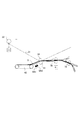
本発明の第1実施形態に係る画像形成装置1について、図1から図6を参照しながら説明する。まず、第1実施形態に係る画像形成装置1の全体構成について、図1及び図2を参照しながら説明する。図1は、本発明の第1実施形態に係る画像形成装置1の全体構造を模式的に示す断面図である。図2は、第1実施形態に係る画像形成装置1の二次転写部4を模式的に示す部分断面図である。
<First Embodiment>
An
図1に示すように、画像形成装置1は、シートSを給送するシート給送部2と、シートSに転写するトナー像を形成する画像形成部3と、トナー像が一次転写される中間転写ベルト31と、トナー像をシートSに二次転写する二次転写部4と、を備えている。以下においては、シート給送部2によるシートSの二次転写部4までの給送プロセス、画像形成部3による画像形成プロセス、二次転写部4による二次転写プロセス及びそれ以降のプロセスを中心に、画像形成装置1の構成と共に説明する。
As shown in FIG. 1, the
まず、シート給送部2によるシートSの二次転写部4までの給送プロセスについて説明する。シートSは、画像形成装置1の下部に設けられた給送カセット61,62,63,64に収納されており、給送ローラ61a,62a,63a,64aによりそれぞれの給送カセット61〜64から給送される。なお、本実施形態においては、画像形成装置1の側部に手差し給送可能な手差し給送トレイ65が設けられており、シートSは、給送ローラ65aにより手差し給送トレイ65からも給送可能に構成されている。
First, the feeding process of the sheet S to the
給送ローラ61a〜65aにより給送されたシートSは、分離手段で1枚ずつ分離され、搬送パス81を介して二次転写部4のシート搬送方向における上流(以下、単に「上流」という)に配置されているレジストレーションローラ対76に搬送される。レジストレーションローラ対76では、給送されるシートSの先端をニップ部に突き当てることによってループを形成させ、シートSの先端は、ループを形成することによりレジストレーションローラ対76のニップ部に沿って倣われる。これにより、シートSの斜行が補正される。また、レジストレーションローラ対76では、シートSへの画像形成のタイミング、即ち、トナー像が一次転写された中間転写ベルト31の回転に合わせて、所定のタイミングで二次転写部4にシートSを搬送する。このように、レジストレーションローラ対76は、シートSの斜行を補正し、所定のタイミグで二次転写部4に搬送する。なお、図2に示すように、レジストレーションローラ対76は、レジストレーションローラ対駆動モータ(以下、単に「レジモータ」という)M1に電気的に接続されており、レジモータM1により回転駆動される。
The sheets S fed by the feeding
次に、画像形成部3による画像形成プロセスについて説明する。画像形成部3は、像担持体としの感光体11Y,11M,11C,11Kと、帯電部12Y,12M,12C,12Kと、露光部13Y,13M,13C,13Kと、現像部14Y,14M,14C,14Kと、を備えている。また、画像形成部3は、一次転写部35Y,35M,35C,35Kと、感光体クリーナ15Y,15M,15C,15Kと、を備えている。なお、感光体、帯電部、現像部及び感光体クリーナは、プロセスカートリッジとしてユニット化されており、本実施形態においては、イエロー(Y)、マゼンタ(M)、シアン(C)及びブラック(Bk)の4色のプロセスカートリッジが設けられている。
Next, an image forming process by the
画像形成部3では、まず、帯電部12Yにより表面を一様に帯電された状態で回転する感光体11Yに対し、送られてきた画像情報の信号に基づいて、露光部13Yが発光し感光体11Yに静電潜像を形成する。感光体11Yに形成された静電潜像は、現像部14Yによりイエロー(Y)のトナー現像が行われ、感光体11Yにイエローのトナー像が形成される。イエローのトナー像が形成されると、次に、一次転写部35Yにより所定の加圧力及び静電的負荷バイアスが与えられ、中間転写ベルト31にイエローのトナー像が一次転写される。イエローのトナー像が一次転写されると、同様に、マゼンタ(M)、シアン(C)及びブラック(Bk)の各トナー像が形成され、順次、中間転写ベルト31に一次転写される。このように、イエロー(Y)、マゼンタ(M)、シアン(C)及びブラック(Bk)の各トナー像が中間転写ベルト31に重畳転写されることにより、中間転写ベルト31にフルカラー(4色)のトナー像が形成される。
In the
中間転写ベルト31は、一次転写されたフルカラーのトナー像を担持すると共に、上述のシートSの搬送プロセスに対して同様のタイミングでフルカラーのトナー像を二次転写部4まで搬送する。中間転写ベルト31は、駆動ローラ33、テンションローラ34及び二次転写内ローラ32に張架されており、駆動ローラ33が回転駆動することにより、図1に示す矢印B方向に回転する。なお、駆動ローラ33は、中間転写ベルト駆動モータ(以下、「ITBモータ」という)M2に電気的に接続されており、ITBモータM2により回転駆動される。
The
次に、二次転写部4による二次転写プロセス及びそれ以降のプロセスについて説明する。二次転写部4は、二次転写内ローラ32と、二次転写内ローラ32と対向する二次転写外ローラ41と、を備えている。二次転写部4は、二次転写内ローラ32と二次転写外ローラ41とのニップ部で、シートSに所定の加圧力と静電的負荷バイアスを与えることでシートS上にフルカラーのトナー像を二次転写する。
Next, the secondary transfer process by the
二次転写部4でシートSにフルカラーのトナー像が二次転写されると、シートSは、搬送手段としての吸着搬送ベルト42により定着部5へと搬送される。吸着搬送ベルト42は、搬送ベルト駆動ローラ及び搬送ベルト張架ローラによって張架されており、二次転写部4から定着部5へシートSが搬送される方向に回転駆動されている。また、吸着搬送ベルト42には無数の吸引用空気穴が設けられており、吸着搬送ベルト42は、ファンにより生成される負圧によって吸着搬送ベルト面にシートSを吸着させて搬送する。
When the full-color toner image is secondarily transferred to the sheet S by the
二次転写部4から吸着搬送ベルト42までの間のシート搬送経路Pは、二次転写部4と吸着搬送ベルト42との間に配置される下ガイド43により規定されている。二次転写部4ではトナー像はシートSの上面に転写されるため、下ガイド43の上方にはシートSの上面をガイドする上ガイドは設けられていない。したがって、シートSは下ガイド43の上面に沿って案内される。
A sheet conveyance path P from the
また、シート搬送経路Pの下方には、シート搬送経路Pに沿って搬送される二次転写後のシートSの有無を検知する検知センサSNが配置されている。検知センサSNは、光を照射してシートSがある場合には信号を出力する反射式のセンサであり、シート搬送経路Pの下側から下ガイド43に形成されている不図示の開口から上方に光を照射するように配置されている。そして、後述する制御部(CPU)10は、所定のタイミングで検知センサSNがシート搬送経路P上にシートSが無いときに発生する信号に基づいて分離不良ジャムが発生したと判断する。分離不良ジャム及び分離不良ジャムが発生した場合の制御部(CPU)10による制御動作については、後に詳述する。
Further, below the sheet conveyance path P, a detection sensor SN that detects the presence or absence of the sheet S after the secondary transfer conveyed along the sheet conveyance path P is disposed. The detection sensor SN is a reflective sensor that emits light and outputs a signal when the sheet S is present, and is upward from an opening (not shown) formed in the
定着部5は、対向するローラ若しくはベルト等による所定の加圧力と、ヒータ等の熱源による所定の熱を加えて、シートSに二次転写されたトナー像を溶融固着させる。トナー像が定着されたシートSは、排出搬送パス82を介して排出トレイ66上に排出される。
The fixing unit 5 melts and fixes the toner image secondarily transferred to the sheet S by applying a predetermined pressure by an opposing roller or belt and a predetermined heat by a heat source such as a heater. The sheet S on which the toner image is fixed is discharged onto the
また、シートSの両面に画像形成を行う場合には、シートSは、反転パス83に搬送され、反転パス83からスイッチバックパス84へと引き込まれる。そして、反転Bローラ対79の回転方向を正逆転させること(スイッチバック動作)で先後端が入れ替えられ、両面搬送パス85へと搬送される。その後、給送カセット61〜64又は手差し給送トレイ65から給送されてくる後続ジョブのシートSとタイミングを合わせて再合流し、レジストレーションローラ対76を経て二次転写部4に再搬送される。なお、裏面(2面目)の画像形成プロセスに関しては、上述の表面(1面目)の場合と同様なので説明を省略する。また、シートSを反転排出させる場合には、定着部5をシートSが通過した後、反転パス83からスイッチバックパス84へと引き込む。そして、反転Aローラ対78及び反転Bローラ対79の逆転により、送り込まれた際の後端を先頭にして、送り込まれた方向と反対向きに退出させ、排出トレイ66に排出される。
When image formation is performed on both sides of the sheet S, the sheet S is conveyed to the reversing path 83 and drawn from the reversing path 83 to the
次に、画像形成装置1の制御部10によるシートSの分離不良ジャムの発生時の停止制御について、図3から図6を参照しながら説明する。まず、分離不良ジャムについて、図3(a)から図4(e)を参照しながら説明する。
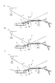
Next, stop control when the
図3(a)は、シートSがループを形成して斜行を補正する状態を示す部分断面図である。図3(b)は、所定のタイミングで二次転写部4にシートSが搬送された状態を示す部分断面図である。図3(c)は、中間転写ベルト31から分離されずにシートSが搬送される状態を示す部分断面図である。図4(a)は、シートSがループを形成して斜行を補正する状態を示す部分断面図である。図4(b)は、所定のタイミングで二次転写部4にシートSが搬送された状態を示す部分断面図である。図4(c)は、シートSの先端が検知センサSNに接触する状態を示す部分断面図である。図4(d)は、検知センサSNに接触したシートSが中間転写ベルト31に引き寄せられる状態を示す部分断面図である。図4(e)は、中間転写ベルト31に引き寄せされたシートSが中間転写ベルト31に貼り付いて搬送される状態を示す部分断面図である。
FIG. 3A is a partial cross-sectional view illustrating a state in which the sheet S forms a loop and corrects skew. FIG. 3B is a partial cross-sectional view illustrating a state where the sheet S is conveyed to the
図3(a)に示すように、給送カセット61〜64から給送されるシートSは、レジストレーションローラ対76のニップ部に突き当ててループを形成することにより先端をニップ部に沿って倣わせ、斜行が補正される。シートSの斜行が補正されると、シートSは、画像形成部3での画像形成のタイミングに合わせて二次転写部4へ送り出されるようにレジストレーションローラ対76にて待機している。その後、図3(b)に示すように、中間転写ベルト31の回転に合わせて、所定のタイミングにてシートSが二次転写部4へ搬送される。
As shown in FIG. 3A, the sheet S fed from the feeding
ここで、制御部10は、図3(c)に示すように、シートSが中間転写ベルト31から分離されず、検知センサSNが所定時間内にシートSを検知しなかった場合に、分離不良ジャムと判断する。しかし、中間転写ベルト31は感光体11Y等に接触しており、分離不良ジャムと判断してからITBモータM2を停止させても中間転写ベルト31の自重による慣性力や感光体11Yの慣性力等の影響により瞬時に中間転写ベルト31を停止させることはできない。そのため、例えば、搬送方向長さの短い小サイズのシートでは、中間転写ベルト31のベルト面に貼り付いたまま定着部5の上方を過ぎて画像形成部3に入り込んでしまうおそれがある。特に、高生産性を要求される画像形成装置では、中間転写ベルト31の回転速度が速いため、顕著にこのような状況が生じる。
Here, as illustrated in FIG. 3C, the
また、シートSの先端が中間転写ベルト31から分離されたとしても、シートSは、二次転写部4にて印加された静電的負荷バイアスによってチャージアップしている。そのため、図4(c)に示すように、シートSの先端が、一端、検知センサSNで検知できる位置にあっても、図4(d)に示すように、シートSに中間転写ベルト31のベルト面に引き寄せる力が働いている。これにより、図4(e)に示すように、再度、分離されたシートSが中間転写ベルト31のベルト面に貼り付いてしまうこともある。
Even if the leading edge of the sheet S is separated from the
この場合、検知センサSNが一度シートSの先端を検知しているため、制御部10は、分離不良ジャムと判断することができない。そのため、検知センサSNの更に下流に配置された次のシート検知センサ等でジャムの判断をすることになり、分離不良ジャムを検知するのが遅くなる。また、分離不良ジャムと判断した時にはすでにシートSの先端が、シート搬送経路Pから外れて画像形成部3等に入り込んでしまっているおそれもある。例えば、搬送方向長さの短い小サイズのシートを搬送していた場合には、シートの後端まで全て画像形成部3等に入り込んでしまう場合もあり、シートSがすべて画像形成部3等に入り込んでしまうとユーザによるジャム処理は困難となる。
In this case, since the detection sensor SN has once detected the leading edge of the sheet S, the
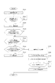
以上を踏まえて、第1実施形態に係る画像形成装置1の制御部10による分離不良ジャム時の停止制御について、図5及び図6を参照しながら説明する。図5は、第1実施形態に係る画像形成装置1の分離不良ジャム時に停止制御を行う制御部10のブロック図である。図6は、第1実施形態に係る画像形成装置1の制御部10による分離不良ジャムの停止制御を示すフローチャートである。
Based on the above, stop control at the time of separation failure jam by the
図5に示すように、第1実施形態に係る画像形成装置1の制御部10は、レジモータM1及びITBモータM2に電気的に接続されている。制御部10は、所定の画像信号が入力されると、レジモータM1及びITBモータM2を駆動制御すると共に、検知センサSNによるシートSの検知に基づいて、レジモータM1及びITBモータM2の停止制御を行う。以下、制御部10による停止制御について説明する。
As shown in FIG. 5, the
画像形成装置1において、プリントジョブが開始されると、シート給送部2による搬送プロセスに準じてシートSの搬送が開始され、搬送されたシートSは、レジストレーションローラ対76で斜行が補正された状態で待機する。これと並行して、画像形成部3による画像形成プロセスに準じて画像の形成が開始される。ここで、制御部10が所定の画像信号を受け取ると(ステップS101)、制御部10は、画像信号を受けてからレジストレーションローラ対76で停止しているシートSの搬送開始のタイミングを待つ(ステップS102)。そして、シートSの搬送開始のタイミングとなったらレジモータM1の駆動を開始し、レジストレーションローラ対76で待機しているシートSを二次転写部4に搬送する(ステップS103)。
In the
レジストレーションローラ対76により二次転写部4に搬送されたシートSは、二次転写部4でフルカラーのトナー像が二次転写され、吸着搬送ベルト42に搬送される。二次転写部4と吸着搬送ベルト42との間のシート搬送経路Pには、シートSの有無を検知する検知センサSNが配置されており、二次転写部4を通過したシートSは、まず、下ガイド43に案内されて検知センサSNの検知位置へと搬送される。
The sheet S conveyed to the
ここで、制御部10は、シート搬送経路P上のシートSの有無について最初の判断を行う。具体的には、制御部10は、レジモータM1の駆動開始から所定時間以内に検知センサSNがシートSの先端を検知したか否かによりシートSの有無の判断を行う(ステップS104)。
Here, the
なお、所定時間(予定時間)とは、レジモータM1の駆動開始からシートSがシート搬送経路Pの検知センサSNまで搬送される称呼時間に、シート搬送速度のバラツキ等を考慮して決めたマージン(例えば、60msec)を加えた時間である。シート搬送速度のバラツキ等としては、例えば、レジストレーションローラ対76の部品公差等によるシート搬送速度のバラツキ、耐久によるレジストレーションローラ対76のローラ表面抵抗の低下によるシート搬送速度のバラツキ等がある。また、例えば、シート搬送経路の搬送抵抗による検知センサSNへの到達時間のバラツキ、シートSの剛度の違いによる不図示の搬送ガイドとシートSの抵抗の違いによるシート搬送速度のバラツキ等がある。
Note that the predetermined time (scheduled time) is a margin that is determined in consideration of variations in sheet conveyance speed, etc., in the nominal time when the sheet S is conveyed to the detection sensor SN of the sheet conveyance path P from the start of driving of the registration motor M1. For example, 60 msec) is added. As variations in sheet conveyance speed, for example, there are variations in sheet conveyance speed due to component tolerances of the
このように、シートSの先端が検知センサSNに到達すると予定される時間を基準としてシートSが分離不良ジャムを起こしたかどうかを判断する。そして、ステップS104でシート搬送経路PのシートSの有無について最初の判断を行うのは、明らかな分離不良ジャムが早期に検知できれば、早くレジストレーションローラ対76を停止することができるためである。分離不良ジャム時に早くレジストレーションローラ対76を停止できれば、例えば、無駄なトナー消費を減らすことができる。また、画像形成部3にシートSが入り込むのを防止したりシートSが画像形成部3に入り込む量を少なくしたりできる。
In this way, it is determined whether or not the sheet S has caused the separation failure jam based on the time when the leading edge of the sheet S reaches the detection sensor SN. In step S104, the first determination as to the presence or absence of the sheet S in the sheet conveyance path P is because the
検知センサSNが所定時間内にシートSの先端を検知すると、シートSは、そのまま吸着搬送ベルト42に向かって搬送される。次に、制御部10は、レジモータM1の駆動開始からシートSの先端が吸着搬送ベルト42のベルト面上まで送られる時間を計算する。そして、計算した時間が経過したかを判断し(ステップS105)、経過した時点(タイミング)で検知センサSNに再度シートSの有無を検知させる(S106)。制御部10が、検知センサSNからの検知信号によりシート搬送経路PにシートSが有ることを判断した場合には、シートSは、そのまま定着部5に搬送され(ステップS107)、プリントジョブが終了する。
When the detection sensor SN detects the leading edge of the sheet S within a predetermined time, the sheet S is conveyed toward the
ここで、シートSの先端をステップS104で検知センサSNにて検知したにも関わらず、再度、検知センサSNによる検知を行い、分離不良ジャムの判断を行うのは、シートSが中間転写ベルト31に引き寄せられてジャムとなることがあるからである。例えば、図5(c)から図5(e)に示したように、シートSの先端を検知センサSNが検知した後においても、シートSが中間転写ベルト31に引き寄せられて中間転写ベルト31のベルト面に貼り付いてジャムとなることがあるからである。
Here, although the leading edge of the sheet S is detected by the detection sensor SN in step S104, the detection by the detection sensor SN is performed again to determine the separation failure jam. This is because they may be attracted to the jam and become jammed. For example, as shown in FIGS. 5C to 5E, even after the detection sensor SN detects the leading edge of the sheet S, the sheet S is attracted to the
また、検知センサSNによる2度目の検知をシートSの先端が吸着搬送ベルト42のベルト面に到達するタイミングで行うのは、一旦シートSが吸着搬送ベルト42に吸着されると、シートSが中間転写ベルト31に引き寄せられることがないためである。なお、本実施形態では、二次転写部4で転写されたシートを吸着搬送ベルト42で搬送する構成を説明したが、シートSのトナー像を乱さないで搬送できる手段、例えば、静電吸着搬送機構などを用いてもよい。
The second detection by the detection sensor SN is performed at the timing when the leading edge of the sheet S reaches the belt surface of the
ステップS104及びステップS106で所定時間内に検知センサSNがシートSの先端を検知しなかった場合、制御部10は分離不良ジャムと判断する(ステップS108)。そして、直ちにレジモータM1のパルス入力を停止させ、さらに、ITBモータM2を停止させる(ステップS109)。
If the detection sensor SN does not detect the leading edge of the sheet S within a predetermined time in step S104 and step S106, the
ここで、レジモータM1には、ステッピングモータが使用され、ITBモータM2には、DCブラシレスモータが使用されている。また、前述したように、中間転写ベルト31は、自重による慣性力や中間転写ベルト31に接触している感光体11Y等による慣性力等の影響が生じるため、ITBモータM2を停止しても、瞬時に停止することができない。また、レジモータM1に流す電流を切断すると、レジストレーションローラ対76は、すぐに停止するもののレジモータM1に保持トルクが生じないため、ブレーキとしての機能は働かない。すなわち、単にレジモータM1に流す電流を切断しても、慣性等で中間転写ベルト31が回転をし続けて二次転写部4でシートSが搬送された時に、レジストレーションローラ対76もシートSに連れ回りをしてしまい、シートSを停止させることができない。これにより、中間転写ベルト31のベルト面に貼り付いて分離不良ジャムしたと判断されたシートSは、二次転写部4での搬送力により、中間転写ベルト31が停止するまでの間は画像形成部3に向けて入り込んでしまう。
Here, a stepping motor is used as the registration motor M1, and a DC brushless motor is used as the ITB motor M2. Further, as described above, the
そこで、本実施形態においては、レジストレーションローラ対76を駆動するレジモータM1であるステッピングモータを回転させるためのパルス入力は停止させて、保持電流を流しておいてレジモータM1を励磁状態に維持させる。このように、レジモータM1へのパルス入力を停止した後も、レジモータM1に保持電流を流して励磁させておくことによって所定トルクとしての保持トルクを発生させることができる(ステップS110)。レジモータM1へのパルス入力を停止させると、レジストレーションローラ対76は慣性も小さいため、所望の時間(例えば、5msec)で瞬時に停止させることができる。そして、レジモータM1の保持トルクでレジストレーションローラ対76は停止した後も回転が阻止されるため、シートSの移動を規制することができる。すなわち、レジモータM1にパルス入力を停止させて保持電流を流して励磁させることにより、レジストレーションローラ対76にブレーキの機能を持たせて、シートSが中間転写ベルト31に張り付いて搬送されることを防止することができる。
Therefore, in the present embodiment, the pulse input for rotating the stepping motor that is the registration motor M1 that drives the
そして、中間転写ベルト31を駆動するITBモータM2が停止するまでの所定時間が経過したかを判断し(ステップS111)、所定時間経過したらレジモータM1の励磁を停止させる(ステップS112)。これにより、レジストレーションローラ対76のブレーキ力も解除されて、ジャムしたシートSをレジストレーションローラ対76のニップ部から引出すことが可能となる。このように、レジモータM1に保持電流を流すことによって生じる保持トルクをブレーキとして機能させ、シートSをレジストレーションローラ対76のニップ部で挟持して停止させることができる。これにより、ITBモータM2が停止してもすぐに止まらない中間転写ベルト31によってシートSが画像形成部3に入り込んでしまうことを防止することができる。その結果、ユーザによるジャム処理が容易となる。
Then, it is determined whether a predetermined time has elapsed until the ITB motor M2 that drives the
なお、レジモータM1に保持電流を流す時間を中間転写ベルト31が停止するまでとしたが、部品バラツキや負荷イナーシャのバラツキなども考慮して中間転写ベルト31が停止するまでの時間よりも充分に長い時間を設定しておくことが好ましい。このように設定することにより、例えば、レジモータM1に保持電流を流す時間は一定とすることも可能となる。
Note that the time during which the holding current is supplied to the registration motor M1 is set until the
以上のような構成を有する第1実施形態に係る画像形成装置1によれば、以下のような効果を奏する。第1実施形態に係る画像形成装置1は、検知センサSNを二次転写部4と吸着搬送ベルト42との間のシート搬送経路Pに配置する。そのため、中間転写ベルト31から離間可能となり、検知センサSNのセンサ面がトナー等で汚れることを防止することができる。これにより、検知センサSNによる誤検知を軽減させることができる。更に、ベルト面上を搬送するシートを検知する構成に比べて、ベルト面のばたつき等を考慮する必要がないため、設定が容易となると共に、検知も容易に行うことが可能となる。これにより、ニ次転写後のシートSの挙動が不安定な場合においても、コストアップすることなく、分離不良ジャムを検知することが可能になる。
The
また、第1実施形態に係る画像形成装置1は、所定の搬送時間の経過時、例えば、シートSの先端が吸着搬送ベルト42のベルト面上に到達するタイミングで分離不良ジャムを判断する。そのため、シートSの分離不良ジャムによる誤検知を軽減することができる。これにより、分離不良ジャムの検知精度を向上させることができる。
Further, the
また、第1実施形態に係る画像形成装置1は、レジモータM1を停止した後も、慣性等により中間転写ベルト31が停止するまでの所定時間は、レジモータM1に保持電流を流すことによって保持トルクを発生させる。そのため、分離不良ジャムによりレジモータM1を停止させた後においても、レジストレーションローラ対76によって挟持されて保持されるため、シートSが画像形成部3等に入り込んでしまうことを防止することができる。これにより、分離不良ジャムが発生した後においても、容易にジャム紙を取り除くことができる。
In addition, the
<第2実施形態>
次に、本発明の第2実施形態に係る画像形成装置1Aについて、図7及び図8を参照しながら説明する。第2実施形態に係る画像形成装置1Aは、制御部による分離不良ジャムの停止制御が第1実施形態と相違する。そのため、第2実施形態においては、第1実施形態と相違する点、すなわち、制御部による分離不良ジャムの停止制御を中心に説明し、第1実施形態に係る画像形成装置1と同様の構成のものについては、同じ符号を付してその説明を省略する。
Second Embodiment
Next, an image forming apparatus 1A according to a second embodiment of the present invention will be described with reference to FIGS. The image forming apparatus 1A according to the second embodiment is different from the first embodiment in the stop control of the separation failure jam by the control unit. Therefore, in the second embodiment, the difference from the first embodiment, that is, the stop control of the separation failure jam by the control unit will be mainly described, and the configuration similar to that of the
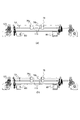
第2実施形態に係る画像形成装置1Aの制御部10による分離不良ジャム時の停止制御について、図7及び図8を参照しながら説明する。図7(a)から図7(c)は、シートサイズの異なる3種類のシートSが二次転写部4を搬送される状態を模式的に示す部分断面図である。図8は、第2実施形態に係る画像形成装置1Aの制御部10による分離不良ジャムの停止制御を示すフローチャートである。
Stop control at the time of poor separation jam by the
第2実施形態に係る画像形成装置1Aにおいて、プリントジョブが開始されると、シート給送部2による搬送プロセスに準じてシートSの搬送が開始され、搬送されたシートSは、レジストレーションローラ対76で斜行が補正された状態で待機する。これと並行して、画像形成部3による画像形成プロセスに準じて画像の形成が開始される。ここで、制御部10が所定の画像信号を受け取ると(ステップS201)、制御部10は、画像信号を受けてからレジストレーションローラ対76で停止しているシートSの搬送開始のタイミングを待つ(ステップS202)。そして、シートSの搬送開始のタイミングとなったらレジモータM1の駆動を開始し、レジストレーションローラ対76で待機しているシートSを二次転写部4に搬送する(ステップS203)。
In the image forming apparatus 1A according to the second embodiment, when a print job is started, the conveyance of the sheet S is started according to the conveyance process by the
レジストレーションローラ対76により二次転写部4に搬送されたシートSは、二次転写部4でフルカラーのトナー像が二次転写され、二次転写部4の下流に設けられた吸着搬送ベルト42に搬送される。二次転写部4と吸着搬送ベルト42との間のシート搬送経路Pには、シートSの有無を検知する検知センサSNが配置されており、二次転写部4を通過したシートSは、下ガイド43に案内されてシート搬送経路Pに配置された検知センサSNの上方へと搬送される。
The sheet S conveyed to the
ここで、制御部10は、レジモータM1の駆動開始からシートSの後端がレジストレーションローラ対76のニップ部との距離が所定の距離(レジストレーションローラ対76の上流近傍位置)となる予定時間を計算する。そして、計算した予定時間が経過したかを判断し(ステップS204)、経過した時点(タイミング)で検知センサSNにシートSの有無を検知させる(ステップS205)。検知センサSNがシート搬送経路PにシートSが有ることを検知した場合には、シートSは、そのまま定着部5に搬送され(ステップS206)、プリントジョブが終了する。一方、検知センサSNがシートSを検知できなかった場合には、分離不良ジャムと判断する。
Here, the
なお、制御部10が分離不良ジャムと判断した場合(ステップS207〜S211)については、第1実施形態の(ステップS108〜S112)と同様であるため、ここではその説明は省略する。
In addition, since it is the same as that of 1st Embodiment (step S108-S112), when the
また、第1実施形態と同様に、シートSの先端にて一度分離不良ジャムを判断しておき、シートSの後端が所定の距離となったとき(レジストレーションローラ対76の上流近傍位置にきたとき)に、再度、分離不良ジャムを判断する構成としてもよい。 Similarly to the first embodiment, once a separation failure jam is determined at the leading edge of the sheet S and the trailing edge of the sheet S reaches a predetermined distance (at a position near the upstream of the registration roller pair 76). The separation failure jam may be determined again.
以上のような構成を有する第2実施形態に係る画像形成装置1Aによれば、第1実施形態と同様の構成により生じる効果に加え、以下のような効果を奏する。第2実施形態に係る画像形成装置1Aは、所定の搬送時間の経過時、例えば、レジモータM1の駆動開始からシートSの後端がレジストレーションローラ対76のニップ部との距離が所定の距離となるタイミングで分離不良ジャムを判断する。そのため、シートサイズにより先端停止位置は異なるようになるが、例えば、長いシートは、より遅いタイミングで分離不良ジャムを判断させることができる。これにより、例えば、シートの挙動が不安定な場合においても、レジストレーションローラ対76で保持トルク(ブレーキ)を掛けられる範囲内で誤検知の少ないタイミングで分離不良ジャムを判断できる(図7(a)から図7(c)参照)。これは、吸着搬送ベルト42のようにシートSの先端を吸着して搬送する機構が二次転写部4の直後の下流に無い場合に特に有効となる。
According to the image forming apparatus 1A according to the second embodiment having the above-described configuration, the following effects can be obtained in addition to the effects generated by the same configuration as in the first embodiment. In the image forming apparatus 1A according to the second embodiment, when a predetermined conveyance time has elapsed, for example, the distance between the rear end of the sheet S and the nip portion of the
<第3実施形態>
次に、本発明の第3実施形態に係る画像形成装置1Bについて、図9から図12を参照しながら説明する。第3実施形態に係る画像形成装置1Bは、シート搬送経路Pに配設される検知センサが第1実施形態と相違する。そのため、第3実施形態においては、第1実施形態と相違する点、すなわち、シート搬送経路Pに設けられる検知センサを中心に説明し、第1実施形態に係る画像形成装置1と同様の構成のものについては、同じ符号を付してその説明を省略する。
<Third Embodiment>
Next, an image forming apparatus 1B according to a third embodiment of the present invention will be described with reference to FIGS. An image forming apparatus 1B according to the third embodiment is different from the first embodiment in the detection sensor disposed in the sheet conveyance path P. Therefore, in the third embodiment, the difference from the first embodiment, that is, the detection sensor provided in the sheet conveyance path P will be mainly described, and the configuration similar to that of the
まず、シート搬送経路Pに設けられるレバー式センサSN1及び反射型光学式センサSN2について、図9から図11を参照しながら説明する。図9(a)は、第3実施形態に係る画像形成装置1Bのレバー式センサSN1を示す概略図である。図9(b)は、通過するシートSに押されてレバー式センサSN1が回動した状態を示す概略図である。図10(a)は、第3実施形態に係る画像形成装置1Bの反射型光学式センサSN2を示す概略図である。図10(b)は、通過するシートSにより反射した反射光を受光する反射型光学式センサSN2を示す概略図である。図11は、第3実施形態に係る画像形成装置1Bの二次転写部4を模式的に示す部分断面図である。
First, the lever type sensor SN1 and the reflective optical sensor SN2 provided in the sheet conveyance path P will be described with reference to FIGS. FIG. 9A is a schematic diagram illustrating the lever sensor SN1 of the image forming apparatus 1B according to the third embodiment. FIG. 9B is a schematic diagram illustrating a state in which the lever sensor SN1 is rotated by being pushed by the passing sheet S. FIG. FIG. 10A is a schematic diagram showing the reflective optical sensor SN2 of the image forming apparatus 1B according to the third embodiment. FIG. 10B is a schematic diagram showing the reflective optical sensor SN2 that receives the reflected light reflected by the sheet S that passes therethrough. FIG. 11 is a partial cross-sectional view schematically showing the
図9に示すように、レバー式センサSN1は、搬送されてくるシートSの先端が当接することにより回動して姿勢の変わるセンサレバーSN11と、センサレバーSN11の姿勢の変化によりON/OFF信号を出力する検知部SN12と、を備えている。レバー式センサSN1は、搬送されているシートSが無い場合は、図9(a)に示すように、センサレバーSN11がシート搬送経路P上に位置するため、検知部SN12がOFF信号を出力する。また、レバー式センサSN1は、搬送されているシートSが有る場合は、図9(b)に示すように、シート搬送経路Pを移動するシートSに押されてセンサレバーSN11が回動するため、検知部SN12がON信号を出力する。 As shown in FIG. 9, the lever type sensor SN1 has a sensor lever SN11 that changes its posture by rotating when the leading edge of the conveyed sheet S comes into contact therewith, and an ON / OFF signal according to a change in the posture of the sensor lever SN11. Is provided. When there is no sheet S being conveyed, the lever sensor SN1 outputs the OFF signal because the sensor lever SN11 is positioned on the sheet conveyance path P as shown in FIG. 9A. . Further, when there is a sheet S being conveyed, the lever sensor SN1 is pushed by the sheet S moving on the sheet conveyance path P and the sensor lever SN11 rotates as shown in FIG. 9B. The detection unit SN12 outputs an ON signal.
図10に示すように、反射型光学式センサSN2は、光を発光する発光素子SN21と、発光素子SN21が発光した光を受光する受光素子SN22と、を備えている。反射型光学式センサSN2は、搬送されているシートSが無い場合は、図10(a)に示すように、発光素子SN21より発せられた光が反射されて戻ってこないためOFF信号を出力する。また、反射型光学式センサSN2は、搬送されているシートSが有る場合は、図10(b)に示すように、発光素子SN21より発せられた光がシートSに反射されて戻ってくるためON信号を出力する。 As shown in FIG. 10, the reflective optical sensor SN2 includes a light emitting element SN21 that emits light and a light receiving element SN22 that receives light emitted from the light emitting element SN21. When there is no sheet S being transported, the reflective optical sensor SN2 outputs an OFF signal because the light emitted from the light emitting element SN21 is reflected and does not return as shown in FIG. 10A. . Further, in the case where there is a sheet S being transported, the reflection type optical sensor SN2 is such that the light emitted from the light emitting element SN21 is reflected back to the sheet S as shown in FIG. 10B. An ON signal is output.
図11に示すように、レバー式センサSN1及び反射型光学式センサSN2は、シート搬送経路Pのほぼ同じ位置に配置されており、制御部10は、レバー式センサSN1と反射型光学式センサSN2からの信号に基づいてシートSの有無を判断する。
As shown in FIG. 11, the lever type sensor SN1 and the reflection type optical sensor SN2 are arranged at substantially the same position in the sheet conveyance path P, and the
次に、第3実施形態に係る画像形成装置1Bの制御部10による分離不良ジャム時の停止制御について、図12を参照しながら説明する。図12は、第3実施形態に係る画像形成装置1Bの制御部10による分離不良ジャムの停止制御を示すフローチャートである。
Next, stop control at the time of poor separation jam by the
第3実施形態に係る画像形成装置1Bにおいて、プリントジョブが開始されると、シート給送部2による搬送プロセスに準じてシートSの搬送が開始され、搬送されたシートSは、レジストレーションローラ対76で斜行が補正された状態で待機する。これと並行して、画像形成部3による画像形成プロセスに準じて画像の形成が開始される。ここで、制御部10が所定の画像信号を受け取ると(ステップS301)、制御部10は、画像信号を受けてからレジストレーションローラ対76で停止しているシートSの搬送開始のタイミングを待つ(ステップS302)。そして、シートSの搬送開始のタイミングとなったらレジモータM1の駆動を開始し、レジストレーションローラ対76で待機しているシートSを二次転写部4に搬送する(ステップS303)。
In the image forming apparatus 1B according to the third embodiment, when a print job is started, the conveyance of the sheet S is started in accordance with the conveyance process by the
レジストレーションローラ対76により二次転写部4に搬送されたシートSは、二次転写部4でフルカラーのトナー像が二次転写され、二次転写部4の下流に設けられた吸着搬送ベルト42に搬送される。二次転写部4と吸着搬送ベルト42との間のシート搬送経路Pには、シートSの有無を検知するレバー式センサSN1及び反射型光学式センサSN2が配置されている。二次転写部4を通過したシートSは、下ガイド43に案内されてシート搬送経路Pに配置されたレバー式センサSN1及び反射型光学式センサSN2の上方へと搬送される(図11参照)。
The sheet S conveyed to the
シート搬送経路PにシートSが搬送されると、制御部10は、レジモータM1の駆動開始から所定時間以内に反射型光学式センサSN2によりシートSの先端を検知したか否かを判断する(ステップS304)。
When the sheet S is transported to the sheet transport path P, the
ここで、所定時間(予定時間)とは、レジモータM1の駆動開始からシートSがシート搬送経路Pの反射型光学式センサSN2まで搬送される称呼時間に、シート搬送速度のバラツキ等を考慮して決めたマージン(例えば、60msec)を加えた時間である。シート搬送速度のバラツキ等としては、例えば、レジストレーションローラ対76の部品公差等によるシート搬送速度のバラツキ、耐久によるレジストレーションローラ対76のローラ表面抵抗の低下によるシート搬送速度のバラツキ等がある。また、例えば、シート搬送経路Pの搬送抵抗による反射型光学式センサSN2への到達時間のバラツキ、シートSの剛度の違いによる不図示の搬送ガイドとシートSの抵抗の違いによるシート搬送速度のバラツキ等がある。
Here, the predetermined time (scheduled time) is a nominal time in which the sheet S is conveyed to the reflective optical sensor SN2 in the sheet conveyance path P from the start of driving of the registration motor M1, taking into account variations in the sheet conveyance speed and the like. This is the time after adding a determined margin (for example, 60 msec). As variations in sheet conveyance speed, for example, there are variations in sheet conveyance speed due to component tolerances of the
また、分離不良ジャムの最初の判断を反射型光学式センサSN2にて行うのは、次の理由による。近年、画像形成装置においては、高生産性が求められており、シートSへの画像形成速度を増加させると共に、先行シートと後続シートとのシート間距離(先行シートの後端と後続シートの先端との距離)を短くすることで高生産性を達成している。このような画像形成装置においては、例えば、画像形成速度を350mm/sec、シート間距離を25mmとした場合、シート間時間(同一位置で先行シートの後端が抜けてから後続シートの先端が到達するまでの時間)は71msecと短くなってしまう。レバー式センサSN1では、先行シートが抜けた後に後続シートを検知するため、センサレバーSN11の姿勢が戻っている必要があり、上述のシート間時間よりも短い時間でセンサレバーSN11の姿勢が戻っていなければならない。 Further, the reason why the reflection type optical sensor SN2 performs the initial determination of the separation failure jam is as follows. 2. Description of the Related Art In recent years, high productivity is demanded in an image forming apparatus, and an image forming speed on a sheet S is increased and an inter-sheet distance between a preceding sheet and a succeeding sheet (the trailing edge of the preceding sheet and the leading edge of the succeeding sheet). To achieve high productivity. In such an image forming apparatus, for example, when the image forming speed is 350 mm / sec and the sheet-to-sheet distance is 25 mm, the sheet-to-sheet time (the leading edge of the succeeding sheet reaches after the trailing edge of the preceding sheet comes off at the same position). (Time until) is shortened to 71 msec. In the lever sensor SN1, the posture of the sensor lever SN11 needs to be returned in order to detect the subsequent sheet after the preceding sheet is removed, and the posture of the sensor lever SN11 has returned in a time shorter than the above-described inter-sheet time. There must be.
通常、レバー式センサSN1のセンサレバーSN11は、シートSの先端が当接することで姿勢を変え、センサレバーSN11の姿勢の変化を検知部SN12が検知することによりシートSの有無を検知している。そのため、搬送中のシートSにダメージを与えたり、搬送負荷にならないようにするため、センサレバーSN11の姿勢を保つためのバネ圧は、可能な限り弱く設定されている。これにより、センサレバーSN11の姿勢の戻り時間は100msec程度かかってしまうこともあり、シート間時間よりも長くなってしまう場合がある。その結果、高生産性の画像形成装置においては、センサレバーSN11の戻り時間を考慮する必要のない反射型光学式センサSN2でステップS304の判断を行うことが好ましい。 Normally, the sensor lever SN11 of the lever sensor SN1 changes its posture when the leading edge of the sheet S comes into contact, and the detection unit SN12 detects the presence or absence of the sheet S by detecting a change in the posture of the sensor lever SN11. . For this reason, the spring pressure for maintaining the posture of the sensor lever SN11 is set as weak as possible so as not to damage the sheet S being conveyed or to cause a conveyance load. As a result, the return time of the posture of the sensor lever SN11 may take about 100 msec, and may be longer than the time between sheets. As a result, in a highly productive image forming apparatus, it is preferable to perform the determination in step S304 with the reflective optical sensor SN2 that does not need to consider the return time of the sensor lever SN11.
反射型光学式センサSN2により、所定時間内にシートSの先端を検知した場合、シートSは、吸着搬送ベルト42に搬送される。シートSが吸着搬送ベルト42に搬送されると、制御部10はレジモータM1の駆動開始からシートSの先端が吸着搬送ベルト42の吸着搬送ベルト面上まで送られる時間を計算し、その時間が経過するのを待つ(ステップS305)。そして、計算した時間が経過した時点で、レバー式センサSN1及び反射型光学式センサSN2によりシートSが検知できているかを確認する(ステップS306)。ここで、レバー式センサSN1及び反射型光学式センサSN2の両方がシートSを検知できていれば、シートSは、そのまま定着部5に搬送され(ステップS307)、プリントジョブが終了する。一方、レバー式センサSN1及び反射型光学式センサSN2の両方がシートSを検知できなかった場合には、分離不良ジャムと判断する(ステップS308)。
When the leading end of the sheet S is detected within a predetermined time by the reflective optical sensor SN2, the sheet S is conveyed to the
なお、制御部10が分離不良ジャムと判断した場合(ステップS308〜S312)については、第1実施形態の(ステップS108〜S112)と同様であるため、ここではその説明は省略する。
In addition, since it is the same as that of (step S108-S112) of 1st Embodiment about the case where the
以上のような構成を有する第3実施形態に係る画像形成装置1Bによれば、第1実施形態と同様の構成により生じる効果に加え、以下のような効果を奏する。第3実施形態に係る画像形成装置1Bは、シートSの先端の分離不良ジャム判断を、まず、反射型光学式センサSN2にて行い、2度目の分離不良ジャム判断には、レバー式センサSN1及び反射型光学式センサSN2の両方のセンサにて行っている。そのため、例えば、2面目のシートSを検知する場合、反射型光学式センサSN2ではシートSの先端余白の白色部は検知することが可能であるが、2度目の検知を行う際には、センサ面側に1面目で転写、定着済みのトナー像がのっている部分を検知する必要がある。特に、シートS上のトナーが黒色の場合には、反射光量が少なくなってしまい、シートSを識別するための閾値の設定が難しく、誤検知が生じ易いが、画像形成装置1Bによれば、これを防止することができる。 According to the image forming apparatus 1B according to the third embodiment having the above-described configuration, the following effects can be obtained in addition to the effects generated by the same configuration as in the first embodiment. In the image forming apparatus 1B according to the third embodiment, the leading edge separation of the sheet S is first determined by the reflective optical sensor SN2, and the second separation failure jam determination is performed using the lever sensor SN1 and This is performed by both sensors of the reflective optical sensor SN2. Therefore, for example, when detecting the second sheet S, the reflective optical sensor SN2 can detect the white portion of the leading margin of the sheet S, but when performing the second detection, the sensor It is necessary to detect the portion where the toner image transferred and fixed on the first surface is on the surface side. In particular, when the toner on the sheet S is black, the amount of reflected light is small, and it is difficult to set a threshold value for identifying the sheet S, and erroneous detection is likely to occur. However, according to the image forming apparatus 1B, This can be prevented.
また、分離不良ジャムの検知精度を向上させることができると共に、分離不良ジャムによりレジモータM1を停止させた後においても、シートSが画像形成部3等に入り込んでしまうことを防止することができる。これにより、分離不良ジャムが発生した後においても、容易にジャム紙を取り除くことができる。
Further, it is possible to improve the detection accuracy of the separation failure jam and to prevent the sheet S from entering the
なお、第2実施形態のように、シートSの後端位置を見て分離不良ジャムを判断する場合においてもレバー式センサSN1と反射型光学式センサSN2の複数のセンサにて分離不良ジャムを判断することで同等の効果が得られる。 As in the second embodiment, even when the separation end jam is determined by looking at the rear end position of the sheet S, the separation failure jam is determined by a plurality of sensors of the lever sensor SN1 and the reflective optical sensor SN2. By doing so, the same effect can be obtained.
<第4実施形態>
次に、本発明の第4実施形態に係る画像形成装置1Cについて、図13から図15を参照しながら説明する。第4実施形態に係る画像形成装置1Cは、搬送されるシートSの斜行を補正するレジストレーションローラ対76が第1実施形態と相違する。そのため、第4実施形態においては、第1実施形態と相違する点、即ち、レジストレーションローラ対76を中心に説明し、第1実施形態に係る画像形成装置1と同様の構成のものについては、同じ符号を付してその説明を省略する。
<Fourth embodiment>
Next, an image forming apparatus 1C according to a fourth embodiment of the present invention will be described with reference to FIGS. An
給送カセット61〜64が、画像に対してシート搬送方向と直交する方向(以下、「幅方向」という)にずれていたり、斜めに配置されていたりすると、給送カセット61〜64から送り出されたシートSの幅方向の位置ズレや斜行が生じるという問題がある。さらに、給送カセット61〜64から給送されたシートSが、搬送途中で幅方向の位置ズレや斜行を生じることもある。このように、二次転写部4に供給されるシートSが幅方向にズレたり斜行が生じたりすると、画像の印字位置とシートSとのズレが生じてしまうことがある。そこで、画像印字精度を第1実施形態の構成よりも更に向上させる構成として、第4実施形態では、シートSの先端突き当てによる斜行補正に加えて、レジストレーションローラ対76のシフトによるシートSの幅方向の位置補正の構成を用いている。なお、レジストレーションローラ対76のシフト機構については後に説明する。
When the feeding
ここで、連続給送ジョブでは、シートSの幅方向の位置補正を行った後に、次のシートSがレジストレーションローラ対76に搬送されてくる前に、レジストレーションローラ対76を所定のホームポジション位置(以下、「HP位置」という)に戻す必要がある。レジストレーションローラ対76をHP位置に戻す動作は、連続給送ジョブにおいて、生産性を低下させる問題がある。そのため、シートSをレジストレーションローラ対76と二次転写部4とでシートSを搬送している所定のタイミングでレジストレーションローラ対76を離間させてからHP位置に戻す構成が用いられる。なお、レジストレーションローラ対76の離間は、レジストレーションローラ対76をHP位置に戻す以外に、レジストレーションローラ対76と二次転写部4とのアライメントずれや圧バランスずれ等により発生する画像とシートの歪みの低減も図っている。
Here, in the continuous feeding job, after correcting the position of the sheet S in the width direction, the
まず、レジストレーションローラ対76の離間機構について、図13を参照しながら説明する。図13(a)は、第4実施形態に係る画像形成装置1Cのレジストレーションローラ対76を離間させる離間機構を示す図である。図13(b)は、図13(a)に示すレジストレーションローラ対76を離間させた状態を示す図である。
First, the separation mechanism of the
図13に示すように、レジストレーションローラ対76は、レジモータM1に接続されたレジストレーション駆動ローラ76aと、レジストレーション駆動ローラ76aに圧接して従動回転するレジストレーション従動ローラ76bと、を備えている。レジストレーション従動ローラ76bは、レジストレーションローラ加圧バネ113によって、レジストレーション駆動ローラ76aに向かって付勢されている。
As shown in FIG. 13, the
レジストレーションローラ対76は、レジストレーションローラ対離間モータ(以下、「レジローラ離間モータ」という)M3がカムギア123を図13(a)に示す位置で保持することで、軸間がLaとなり、ニップ部が形成される。また、レジストレーションローラ対76は、レジローラ離間モータM3がカムギア123を図13(b)に示す位置に保持することで、軸間がLb(>La)となり、レジストレーション駆動ローラ76aとレジストレーション従動ローラ76bとが離間する。
The
レジストレーションローラ対76のシート搬送方向の上流又は下流には、搬送されるシートSの幅方向の位置を検知するための不図示の幅検知センサ(CCD等)が設けられている。制御部10は、不図示の幅検知センサの検知信号に基づいて、シートSと二次転写部4で転写される画像の幅方向の位置のズレ量を検知する。シートSと画像との幅方向の位置ズレ量を補正するために、レジストレーションローラ対76はシートSを挟持した状態で幅方向の位置ズレが無くなるように幅方向にシフト移動する。これにより、シートSと二次転写部4とでシートSに転写される画像とのズレを防止して画像位置精度を向上させることができる。そして、シートSの幅方向の位置ズレを補正した後に、後続シートの位置ズレ補正を行うために、レジストレーションローラ対76は所定のタイミングでHPの位置に戻される。
An upstream or downstream of the
以上を踏まえて、第4実施形態に係る画像形成装置1Cの制御部10による分離不良ジャム時の停止制御について、図14及び図15を参照しながら説明する。図14は、第4実施形態に係る画像形成装置1Cの分離不良ジャム時に停止制御を行う制御部10のブロック図である。図15は、第4実施形態に係る画像形成装置1Cの制御部10による分離不良ジャムの停止制御を示すフローチャートである。
Based on the above, stop control at the time of poor separation jam by the
図14に示すように、第4実施形態に係る画像形成装置1Cの制御部10は、レジモータM1、ITBモータM2及びレジローラ離間モータM3に電気的に接続されている。制御部10は、所定の画像信号が入力されると、レジモータM1、ITBモータM2及びレジローラ離間モータM3を駆動制御する。また、検知センサSNによるシートSの検知に基づいて、レジモータM1、ITBモータM2及びレジローラ離間モータM3の停止制御を行う。以下、制御部10による停止制御について説明する。なお、ステップS401〜ステップS406及びステップS409〜ステップS413までは、第1実施形態と同様であるため、ここでは具体的な説明は省略する。
As shown in FIG. 14, the
図15に示すように、ステップS406で分離不良ジャムが発生しないと判断した場合には、検知センサSNがシートSを検知した後に、レジローラ離間モータM3を駆動して、離間機構を駆動させる。離間機構が駆動すると、レジストレーション駆動ローラ76aとレジストレーション従動ローラ76bとが離間する。レジストレーション駆動ローラ76aとレジストレーション従動ローラ76bとが離間すると、離間したレジストレーションローラ対76をHP位置に戻すようにシフトさせる(ステップS407)。シートSは、定着部5に送られてトナー像が定着される(ステップS408)。
As shown in FIG. 15, when it is determined in step S406 that a separation failure jam does not occur, after the detection sensor SN detects the sheet S, the registration roller separation motor M3 is driven to drive the separation mechanism. When the separation mechanism is driven, the
一方、ステップS406で分離不良ジャムが発生したと判断した場合には、第1実施形態と同じようにレジストレーションローラ対76を停止させて、シートSが画像形成部3に入り込まないようにする(ステップS409〜S413)。
On the other hand, if it is determined in step S406 that a separation failure jam has occurred, the
以上のような構成を有する第4実施形態に係る画像形成装置1Cによれば、第1実施形態と同様の構成により生じる効果に加え、以下のような効果を奏する。第4実施形態に係る画像形成装置1Cは、レジストレーションローラ対76を幅方向にシフト可能に構成されている。そのため、画像形成装置1Cは、給送カセット61〜64から送り出されたシートSの幅方向の位置ズレや斜行が生じた場合においても、画像の印字位置とシートSとのズレを防止することができる。その結果、画像印字精度を向上させることができる。
According to the
なお、第4実施形態に係るレジストレーションローラ対76の離間機構の制御を第2実施形態及び第3実施形態の構成に適用してもよい。
Note that the control of the separation mechanism of the
<第5実施形態>
次に、本発明の第5実施形態に係る画像形成装置1Dについて、図16を参照しながら説明する。第5実施形態に係る画像形成装置1Dは、検知センサSNによって分離不良ジャムを検知する前にレジストレーションローラ対76を離間させてHP位置に戻すことが第4実施形態と相違する。そのため、第5実施形態においては、第4実施形態と相違する点、即ち、レジストレーションローラ対76の離間のタイミングを中心に説明し、第4実施形態に係る画像形成装置1Cと同様の構成のものについては、同じ符号を付してその説明を省略する。
<Fifth Embodiment>
Next, an image forming apparatus 1D according to a fifth embodiment of the present invention will be described with reference to FIG. The image forming apparatus 1D according to the fifth embodiment is different from the fourth embodiment in that the
第5実施形態に係る画像形成装置1Dの制御部10による分離不良ジャム時の停止制御について、図16を参照しながら説明する。図16は、第5実施形態に係る画像形成装置1Dの制御部10による分離不良ジャムの停止制御を示すフローチャートである。なお、ステップS501〜ステップS504までは、第1実施形態と同様であるため、ここでは具体的な説明は省略する。
Stop control at the time of poor separation jam by the
二次転写部4を通過したシートSは、検知センサSN上へと搬送され、制御部10はレジモータM1の駆動開始から所定時間以内に検知センサSNでシート先端を検知できたかどうかを判断する。つまり、ジャムとして装置を停止させるかどうかを判断する。検知センサSNにてシートSの先端が検知された場合には、シートSのジャムではないと判断し、制御部10は、レジローラ離間モータM3の駆動を開始させて、レジストレーションローラ対76を離間させる。ここでは、検知センサSNによりシートSのジャムの判断をした後にレジストレーションローラ対76を離間する構成となっているが、シートSが二次転写部4により搬送されていれば、レジストレーションローラ対76の離間タイミングは任意である。そして、レジストレーションローラ対76をHP位置にシフトさせて戻す(ステップS505)。
The sheet S that has passed through the
検知センサSNが所定時間内にシートSの先端を検知すると、シートSは、そのまま吸着搬送ベルト42に向かって搬送される。次に、制御部10は、レジモータM1の駆動開始からシートSの先端が吸着搬送ベルト42のベルト面上まで送られる時間を計算する。そして、計算した時間が経過したかを判断し(ステップS506)、経過した時点(タイミング)で検知センサSNに再度シートSの有無を検知させる(ステップS507)。検知センサSNでシートSが有ることを検知した場合には、シートSは、そのまま定着部5に搬送され(ステップS508)、プリントジョブが終了する。なお、シートSの先端を一度検知センサSNにて検知したにも関わらず、再度、検知センサSNの検知を行いジャムの判断をするのは、第1実施形態で述べた通りである。
When the detection sensor SN detects the leading edge of the sheet S within a predetermined time, the sheet S is conveyed toward the
ステップS504及びステップS507で所定時間内に検知センサSNがシートSの先端を検知しなかった場合、制御部10は分離不良ジャムと判断する(ステップS509)。この判断により、制御部10は、レジローラ離間モータM3の駆動を開始させて、レジストレーションローラ対76をニップさせる。さらに、レジモータM1であるステッピングモータへのパルス入力を停止させ、さらにITBモータM2を停止させる(ステップS510)。
If the detection sensor SN does not detect the leading edge of the sheet S within a predetermined time in step S504 and step S507, the
そして、レジモータM1へのパルス入力を停止した後も、レジモータM1に保持電流を流して励磁させておくことによって、レジモータM1に保持トルクを発生させる(ステップS511)。そして、分離不良ジャムを起こしたシートSをレジストレーションローラ対76のニップ部で挟持した状態で停止させる。そして、ITBモータM2が停止するまでの所定時間が経過したかを判断し(ステップS512)、所定時間経過したらレジモータM1の励磁を停止させる(ステップS513)。これにより、停止させたジャムしたシートSをレジストレーションローラ対76のニップ部から引出すことが可能となる。
Even after the pulse input to the registration motor M1 is stopped, the holding torque is generated in the registration motor M1 by exciting the registration motor M1 with a holding current (step S511). Then, the sheet S in which the poor separation jam occurs is stopped in a state where the sheet S is sandwiched between the nip portions of the
なお、第5実施形態も、第1の実施の形態と同じ効果を奏する。また、第5実施形態のレジストレーションローラ対76の離間機構の制御を前記第2実施形態の構成及び第3実施形態に適用してもよい。
The fifth embodiment also has the same effect as the first embodiment. Further, the control of the separation mechanism of the
以上、本発明の実施形態について説明したが、本発明は上述した実施形態に限定されるものではない。また、本発明の実施形態に記載された効果は、本発明から生じる最も好適な効果を列挙したに過ぎず、本発明による効果は、本発明の実施形態に記載されたものに限定されない。 As mentioned above, although embodiment of this invention was described, this invention is not limited to embodiment mentioned above. In addition, the effects described in the embodiments of the present invention only list the most preferable effects resulting from the present invention, and the effects of the present invention are not limited to those described in the embodiments of the present invention.
例えば、第1実施形態においては、シートSの先端を一度検知センサSNにて検知した後、所定のタイミングで再度検知センサSNの検知を行う構成としたが、本発明においてはこれに限定されない。例えば、1度目のシートSの先端でのジャム判断は行わず、2度目のシートSの先端が吸着搬送ベルト42のベルト面上にくるタイミングでのみでジャムを判断してもよい。
For example, in the first embodiment, the detection sensor SN is once detected at the leading edge of the sheet S, and then the detection sensor SN is detected again at a predetermined timing. However, the present invention is not limited to this. For example, the jam determination at the leading edge of the first sheet S is not performed, and the jam may be determined only when the leading edge of the second sheet S comes on the belt surface of the
また、例えば、第3実施形態においては、2度目の分離不良ジャム判断をレバー式センサSN1及び反射型光学式センサSN2の両方のセンサにて行ったが、本発明においてはこれに限定されない。2度目の分離不良ジャム判断をレバー式センサSN1のみにて行うことも可能である。 Further, for example, in the third embodiment, the second separation failure jam determination is performed by both the lever type sensor SN1 and the reflective optical sensor SN2. However, the present invention is not limited to this. It is also possible to determine the second separation failure jam only by lever type sensor SN1.
1、1A、1B、1C、1D 画像形成装置
4 二次転写部
10 制御部
31 中間転写ベルト
42 吸着搬送ベルト(搬送手段)
76 レジストレーションローラ対
M1 レジモータ(駆動手段)
M2 ITBモータ
SN 検知センサ
SN1 レバー式センサ
SN11 センサレバー
SN12 検知部
SN2 反射型光学式センサ
P シート搬送経路
S シート
DESCRIPTION OF
76 Registration roller pair M1 Registration motor (drive means)
M2 ITB motor SN detection sensor SN1 lever type sensor SN11 sensor lever SN12 detection unit SN2 reflective optical sensor P sheet conveyance path S sheet
Claims (7)
前記中間転写ベルトに一次転写されたトナー像をシートに二次転写する二次転写部と、
前記二次転写部のシート搬送方向における上流に配置され、前記二次転写部でシートに二次転写をするタイミングに合わせてシートの搬送を開始するレジストレーションローラ対と、
前記レジストレーションローラ対を駆動する駆動手段と、
前記二次転写部のシート搬送方向における下流のシート搬送経路に配置され、前記二次転写部で二次転写されて搬送されるシートを検知する検知センサと、
前記検知センサの下流に配置され、二次転写後のシートを搬送する搬送手段と、
前記駆動手段を駆動制御して前記レジストレーションローラ対によるシートの搬送を開始した後、シートの先端が前記搬送手段に到達すると予定される時間が経過したときに、前記検知センサからの信号に基づいて前記シート搬送経路にシートが無いことを判断した場合に前記駆動手段を停止させる制御部と、を備えた、
ことを特徴とする画像形成装置。 In an image forming apparatus in which a toner image formed on an image carrier is primarily transferred to an intermediate transfer belt, and then the primary transferred toner image is secondarily transferred to a sheet to form an image on the sheet.
A secondary transfer portion for secondary transfer of the toner image primarily transferred to the intermediate transfer belt to a sheet;
A registration roller pair disposed upstream of the secondary transfer unit in the sheet conveyance direction and starting conveyance of the sheet in accordance with the timing of secondary transfer to the sheet in the secondary transfer unit;
Drive means for driving the registration roller pair;
A detection sensor that is disposed in a downstream sheet conveyance path in the sheet conveyance direction of the secondary transfer unit, and detects a sheet that is secondarily transferred and conveyed by the secondary transfer unit;
A conveying means disposed downstream of the detection sensor and conveying a sheet after secondary transfer;
Based on a signal from the detection sensor when a period of time when the leading edge of the sheet reaches the conveying unit has elapsed after driving the driving unit and starting conveyance of the sheet by the registration roller pair. A control unit that stops the driving means when it is determined that there is no sheet in the sheet conveyance path,
An image forming apparatus.
前記中間転写ベルトに一次転写されたトナー像をシートに二次転写する二次転写部と、
前記二次転写部のシート搬送方向における上流に配置され、前記二次転写部でシートに二次転写をするタイミングに合わせてシートの搬送を開始するレジストレーションローラ対と、
前記レジストレーションローラ対を駆動する駆動手段と、
前記二次転写部のシート搬送方向における下流のシート搬送経路に配置され、前記二次転写部で二次転写されて搬送されるシートを検知する検知センサと、
前記検知センサの下流に配置され、二次転写後のシートを搬送する搬送手段と、
前記駆動手段を駆動制御して前記レジストレーションローラ対によるシートの搬送を開始した後、シートの後端と前記レジストレーションローラ対のニップ部との距離が所定の距離になると予定される所定時間が経過したときに、前記検知センサからの信号に基づいて前記シート搬送経路にシートが無いことを判断した場合に前記駆動手段を停止させる制御を行う制御部と、を備えた、
ことを特徴とする画像形成装置。 In an image forming apparatus in which a toner image formed on an image carrier is primarily transferred to an intermediate transfer belt, and then the primary transferred toner image is secondarily transferred to a sheet to form an image on the sheet.
A secondary transfer portion for secondary transfer of the toner image primarily transferred to the intermediate transfer belt to a sheet;
A registration roller pair disposed upstream of the secondary transfer unit in the sheet conveyance direction and starting conveyance of the sheet in accordance with the timing of secondary transfer to the sheet in the secondary transfer unit;
Drive means for driving the registration roller pair;
A detection sensor that is disposed in a downstream sheet conveyance path in the sheet conveyance direction of the secondary transfer unit, and detects a sheet that is secondarily transferred and conveyed by the secondary transfer unit;
A conveying means disposed downstream of the detection sensor and conveying a sheet after secondary transfer;
After the driving means is driven and controlled, and the conveyance of the sheet by the registration roller pair is started, a predetermined time when the distance between the rear end of the sheet and the nip portion of the registration roller pair becomes a predetermined distance. A control unit that performs control to stop the driving unit when it is determined that there is no sheet in the sheet conveyance path based on a signal from the detection sensor when it has elapsed,
An image forming apparatus.
前記制御部は、前記駆動モータを停止させた後、前記レジストレーションローラ対が回転しないように前記駆動モータに所定トルクを与える、
ことを特徴とする請求項1又は2に記載の画像形成装置。 The drive means includes a drive motor,
The control unit applies a predetermined torque to the drive motor so that the pair of registration rollers does not rotate after stopping the drive motor.
The image forming apparatus according to claim 1, wherein the image forming apparatus is an image forming apparatus.
前記制御部は、前記レバー式センサと、前記反射型光学式センサと、の両方がシートを検知していない場合に、前記駆動手段を停止させる、
ことを特徴とする請求項1から3のいずれか1項に記載の画像形成装置。 The detection sensor includes a lever sensor that detects the presence or absence of a sheet by detecting a change in the posture of a sensor lever that changes in posture depending on the presence or absence of a sheet, and a reflective optical sensor.
The control unit stops the driving means when both the lever type sensor and the reflective optical sensor are not detecting a sheet,
The image forming apparatus according to claim 1, wherein the image forming apparatus is an image forming apparatus.
前記制御部は、シートの先端が前記搬送手段で搬送されるタイミング又はシートの後端が前記レジストレーションローラ対の上流の近傍位置に位置するタイミングで、前記検知センサがシートを検知した場合に前記離間機構を制御して、前記レジストレーションローラ対を離間させる、
ことを特徴とする請求項1から4のいずれか1項に記載の画像形成装置。 A separation mechanism for separating the pair of registration rollers configured to be separated;
When the detection sensor detects the sheet at the timing when the leading edge of the sheet is conveyed by the conveying means or the timing when the trailing edge of the sheet is positioned in the vicinity of the upstream of the registration roller pair, Controlling the separation mechanism to separate the registration roller pair;
The image forming apparatus according to claim 1, wherein the image forming apparatus is an image forming apparatus.
前記制御部は、シートの先端が前記搬送手段で搬送されるタイミング又はシートの後端が前記レジストレーションローラ対の上流の近傍位置にいるタイミングより前に、前記離間機構を制御して、前記レジストレーションローラ対を離間させ、
シートの先端が前記搬送手段で搬送されるタイミング又はシートの後端が前記レジストレーションローラ対の上流の近傍位置に位置するタイミングで、前記検知センサからの信号に基づいて前記シート搬送経路にシートが無いことを判断した場合に、前記離間機構を制御して前記レジストレーションローラ対をニップさせ、かつ前記駆動手段を停止させる、
ことを特徴とする請求項1から4のいずれか1項に記載の画像形成装置。 A separation mechanism for separating the pair of registration rollers configured to be separated;
The control unit controls the separation mechanism before the timing at which the leading edge of the sheet is conveyed by the conveying means or the timing at which the trailing edge of the sheet is in a position near the upstream of the registration roller pair. The separation roller pair,
At the timing when the leading edge of the sheet is conveyed by the conveying means or the timing when the trailing edge of the sheet is positioned in the vicinity of the upstream of the registration roller pair , the sheet is fed to the sheet conveying path based on a signal from the detection sensor. If it is determined that no, by controlling the separation mechanism is nipped the registration roller pair, and Ru to stop the driving means,
The image forming apparatus according to claim 1, wherein the image forming apparatus is an image forming apparatus.
ことを特徴とする請求項1乃至6のいずれか1項に記載の画像形成装置。 The image forming apparatus according to claim 1, wherein the image forming apparatus is an image forming apparatus.
Priority Applications (1)
| Application Number | Priority Date | Filing Date | Title |
|---|---|---|---|
| JP2012026410A JP5955012B2 (en) | 2011-02-10 | 2012-02-09 | Image forming apparatus |
Applications Claiming Priority (3)
| Application Number | Priority Date | Filing Date | Title |
|---|---|---|---|
| JP2011026764 | 2011-02-10 | ||
| JP2011026764 | 2011-02-10 | ||
| JP2012026410A JP5955012B2 (en) | 2011-02-10 | 2012-02-09 | Image forming apparatus |
Related Child Applications (1)
| Application Number | Title | Priority Date | Filing Date |
|---|---|---|---|
| JP2016119352A Division JP6129384B2 (en) | 2011-02-10 | 2016-06-15 | Image forming apparatus |
Publications (2)
| Publication Number | Publication Date |
|---|---|
| JP2012181518A JP2012181518A (en) | 2012-09-20 |
| JP5955012B2 true JP5955012B2 (en) | 2016-07-20 |
Family
ID=46636953
Family Applications (2)
| Application Number | Title | Priority Date | Filing Date |
|---|---|---|---|
| JP2012026410A Active JP5955012B2 (en) | 2011-02-10 | 2012-02-09 | Image forming apparatus |
| JP2016119352A Active JP6129384B2 (en) | 2011-02-10 | 2016-06-15 | Image forming apparatus |
Family Applications After (1)
| Application Number | Title | Priority Date | Filing Date |
|---|---|---|---|
| JP2016119352A Active JP6129384B2 (en) | 2011-02-10 | 2016-06-15 | Image forming apparatus |
Country Status (2)
| Country | Link |
|---|---|
| US (1) | US9581927B2 (en) |
| JP (2) | JP5955012B2 (en) |
Families Citing this family (12)
| Publication number | Priority date | Publication date | Assignee | Title |
|---|---|---|---|---|
| JP5871879B2 (en) * | 2013-10-10 | 2016-03-01 | キヤノン株式会社 | Image forming apparatus |
| JP6552252B2 (en) * | 2015-04-14 | 2019-07-31 | キヤノン株式会社 | Image forming device |
| JP6742747B2 (en) * | 2016-02-16 | 2020-08-19 | キヤノン株式会社 | Image forming device |
| JP6705273B2 (en) * | 2016-04-21 | 2020-06-03 | コニカミノルタ株式会社 | Image forming device |
| US10324410B2 (en) * | 2016-04-27 | 2019-06-18 | Kyocera Document Solutions Inc. | Image forming apparatus |
| JP6926649B2 (en) * | 2017-05-09 | 2021-08-25 | コニカミノルタ株式会社 | Image forming device |
| US11092913B2 (en) | 2017-06-16 | 2021-08-17 | Konica Minolta, Inc. | Image forming apparatus |
| JP7047264B2 (en) * | 2017-06-16 | 2022-04-05 | コニカミノルタ株式会社 | Image forming device and control method |
| JP7047267B2 (en) * | 2017-07-05 | 2022-04-05 | コニカミノルタ株式会社 | Image forming device and transfer control method |
| JP7091720B2 (en) * | 2018-03-06 | 2022-06-28 | コニカミノルタ株式会社 | Image forming device and transfer control method |
| CN110412843B (en) * | 2018-04-26 | 2021-12-07 | 广州众诺电子技术有限公司 | Serial number switching method and system |
| JP2020052201A (en) * | 2018-09-26 | 2020-04-02 | 富士ゼロックス株式会社 | Image forming apparatus |
Family Cites Families (18)
| Publication number | Priority date | Publication date | Assignee | Title |
|---|---|---|---|---|
| JPH0125955Y2 (en) * | 1980-06-11 | 1989-08-03 | ||
| JPH01197778A (en) * | 1988-02-01 | 1989-08-09 | Minolta Camera Co Ltd | Transfer paper separating device for copying machine |
| JPH05270078A (en) * | 1992-03-24 | 1993-10-19 | Ricoh Co Ltd | Sheet aligning apparatus |
| JPH08123128A (en) * | 1994-10-19 | 1996-05-17 | Fuji Xerox Co Ltd | Image transfer device |
| JP3334481B2 (en) * | 1996-03-13 | 2002-10-15 | ミノルタ株式会社 | Image forming device |
| JP3687296B2 (en) | 1997-08-21 | 2005-08-24 | 富士ゼロックス株式会社 | Image forming apparatus |
| JP3865026B2 (en) * | 1998-11-27 | 2007-01-10 | 富士ゼロックス株式会社 | Image forming apparatus |
| JP2001154497A (en) * | 1999-11-25 | 2001-06-08 | Fuji Xerox Co Ltd | Image forming device |
| JP2003202762A (en) * | 2002-01-09 | 2003-07-18 | Canon Inc | Image forming apparatus |
| US7334788B2 (en) * | 2003-03-24 | 2008-02-26 | Fuji Xerox Co., Ltd. | Sheet feeder for feeding recording sheets while separating these |
| JP4455041B2 (en) * | 2003-12-17 | 2010-04-21 | キヤノン株式会社 | Image forming apparatus |
| US7274904B2 (en) * | 2004-11-15 | 2007-09-25 | Kabushiki Kaisha Toshiba | Image forming apparatus |
| US7398027B2 (en) * | 2005-03-30 | 2008-07-08 | Canon Kabushiki Kaisha | Image forming apparatus with conveyance speed control based in part on loop detection |
| JP4782650B2 (en) * | 2006-09-27 | 2011-09-28 | 株式会社リコー | Image forming apparatus, and conveyance control and image forming control method for image forming apparatus |
| JP5156420B2 (en) * | 2008-02-06 | 2013-03-06 | 京セラドキュメントソリューションズ株式会社 | Image forming apparatus |
| JP2009269736A (en) * | 2008-05-09 | 2009-11-19 | Ricoh Co Ltd | Image forming device |
| JP2010008879A (en) * | 2008-06-30 | 2010-01-14 | Casio Electronics Co Ltd | Image forming apparatus |
| JP2010175927A (en) * | 2009-01-30 | 2010-08-12 | Panasonic Corp | Device for detecting passage of recording medium, recording medium conveyance device including the same and image forming apparatus |
-
2012
- 2012-02-01 US US13/363,678 patent/US9581927B2/en active Active
- 2012-02-09 JP JP2012026410A patent/JP5955012B2/en active Active
-
2016
- 2016-06-15 JP JP2016119352A patent/JP6129384B2/en active Active
Also Published As
| Publication number | Publication date |
|---|---|
| JP2012181518A (en) | 2012-09-20 |
| US9581927B2 (en) | 2017-02-28 |
| US20120207485A1 (en) | 2012-08-16 |
| JP2016164690A (en) | 2016-09-08 |
| JP6129384B2 (en) | 2017-05-17 |
Similar Documents
| Publication | Publication Date | Title |
|---|---|---|
| JP6129384B2 (en) | Image forming apparatus | |
| US9187280B2 (en) | Sheet feeding device, control method for the sheet feeding device, and image forming apparatus incorporating the sheet feeding device | |
| JP5610149B2 (en) | Sheet feeding apparatus and image forming apparatus | |
| JP5451292B2 (en) | Image forming apparatus and sheet conveying method | |
| JP2014034459A (en) | Recording medium conveyance device and image forming apparatus | |
| US8023837B2 (en) | Image forming apparatus capable of preventing a sheet jamming during detected abnormal situations | |
| JP5606486B2 (en) | Skew correction device and image forming apparatus | |
| JP2015196594A (en) | Image formation apparatus | |
| JP6743647B2 (en) | Image forming device | |
| US8973919B2 (en) | Double-feed detection apparatus and image forming apparatus | |
| JP4570941B2 (en) | Paper transport device and image forming apparatus using the same | |
| US10906762B2 (en) | Sheet conveyance apparatus and image forming apparatus | |
| JPH1159962A (en) | Image forming device | |
| JP5545030B2 (en) | Paper feeding and conveying apparatus and image forming apparatus | |
| JP2011132022A (en) | Sheet carrying device and image forming device | |
| JP2011013381A (en) | Image forming apparatus | |
| JP5464880B2 (en) | Image forming apparatus | |
| JP7327021B2 (en) | IMAGE FORMING APPARATUS, IMAGE FORMING APPARATUS CONTROL METHOD AND PROGRAM | |
| US20160039630A1 (en) | Sheet conveying apparatus and image forming apparatus | |
| JP2006137579A (en) | Paper conveying device and image forming device using the same | |
| JP4749276B2 (en) | Image forming apparatus | |
| JP2014061989A (en) | Image forming apparatus | |
| JP5744533B2 (en) | Image forming apparatus | |
| JP2007041421A (en) | Image forming apparatus | |
| JP2015160692A (en) | Sheet feeding device and image formation device |
Legal Events
| Date | Code | Title | Description |
|---|---|---|---|
| RD04 | Notification of resignation of power of attorney |
Free format text: JAPANESE INTERMEDIATE CODE: A7424 Effective date: 20130228 |
|
| A621 | Written request for application examination |
Free format text: JAPANESE INTERMEDIATE CODE: A621 Effective date: 20150109 |
|
| A977 | Report on retrieval |
Free format text: JAPANESE INTERMEDIATE CODE: A971007 Effective date: 20151027 |
|
| A131 | Notification of reasons for refusal |
Free format text: JAPANESE INTERMEDIATE CODE: A131 Effective date: 20151110 |
|
| A521 | Written amendment |
Free format text: JAPANESE INTERMEDIATE CODE: A523 Effective date: 20160112 |
|
| TRDD | Decision of grant or rejection written | ||
| A01 | Written decision to grant a patent or to grant a registration (utility model) |
Free format text: JAPANESE INTERMEDIATE CODE: A01 Effective date: 20160517 |
|
| A61 | First payment of annual fees (during grant procedure) |
Free format text: JAPANESE INTERMEDIATE CODE: A61 Effective date: 20160614 |
|
| R151 | Written notification of patent or utility model registration |
Ref document number: 5955012 Country of ref document: JP Free format text: JAPANESE INTERMEDIATE CODE: R151 |