JP5954726B2 - Apparatus and method for evaluating layers in a multilayer structure - Google Patents
Apparatus and method for evaluating layers in a multilayer structure Download PDFInfo
- Publication number
- JP5954726B2 JP5954726B2 JP2011264460A JP2011264460A JP5954726B2 JP 5954726 B2 JP5954726 B2 JP 5954726B2 JP 2011264460 A JP2011264460 A JP 2011264460A JP 2011264460 A JP2011264460 A JP 2011264460A JP 5954726 B2 JP5954726 B2 JP 5954726B2
- Authority
- JP
- Japan
- Prior art keywords
- unit
- multilayer structure
- axis
- opening
- parameter
- Prior art date
- Legal status (The legal status is an assumption and is not a legal conclusion. Google has not performed a legal analysis and makes no representation as to the accuracy of the status listed.)
- Active
Links
- 238000000034 method Methods 0.000 title claims description 26
- 239000010410 layer Substances 0.000 claims description 76
- 238000001514 detection method Methods 0.000 claims description 35
- 238000011156 evaluation Methods 0.000 claims description 35
- 239000011229 interlayer Substances 0.000 claims description 26
- 230000008859 change Effects 0.000 claims description 20
- 239000000463 material Substances 0.000 claims description 18
- 238000006073 displacement reaction Methods 0.000 claims description 10
- 238000012544 monitoring process Methods 0.000 claims description 9
- 230000001747 exhibiting effect Effects 0.000 claims description 5
- 238000010586 diagram Methods 0.000 description 6
- 238000005259 measurement Methods 0.000 description 5
- 239000004020 conductor Substances 0.000 description 4
- 238000013461 design Methods 0.000 description 3
- 230000006835 compression Effects 0.000 description 1
- 238000007906 compression Methods 0.000 description 1
- 230000004907 flux Effects 0.000 description 1
- 238000007373 indentation Methods 0.000 description 1
- 230000003993 interaction Effects 0.000 description 1
- 238000012986 modification Methods 0.000 description 1
- 230000004048 modification Effects 0.000 description 1
- 230000002093 peripheral effect Effects 0.000 description 1
- 230000008569 process Effects 0.000 description 1
- 238000012360 testing method Methods 0.000 description 1
- 238000004154 testing of material Methods 0.000 description 1
- 230000007704 transition Effects 0.000 description 1
Images


Classifications
-
- G—PHYSICS
- G01—MEASURING; TESTING
- G01B—MEASURING LENGTH, THICKNESS OR SIMILAR LINEAR DIMENSIONS; MEASURING ANGLES; MEASURING AREAS; MEASURING IRREGULARITIES OF SURFACES OR CONTOURS
- G01B7/00—Measuring arrangements characterised by the use of electric or magnetic techniques
- G01B7/14—Measuring arrangements characterised by the use of electric or magnetic techniques for measuring distance or clearance between spaced objects or spaced apertures
-
- G—PHYSICS
- G01—MEASURING; TESTING
- G01B—MEASURING LENGTH, THICKNESS OR SIMILAR LINEAR DIMENSIONS; MEASURING ANGLES; MEASURING AREAS; MEASURING IRREGULARITIES OF SURFACES OR CONTOURS
- G01B7/00—Measuring arrangements characterised by the use of electric or magnetic techniques
- G01B7/02—Measuring arrangements characterised by the use of electric or magnetic techniques for measuring length, width or thickness
- G01B7/06—Measuring arrangements characterised by the use of electric or magnetic techniques for measuring length, width or thickness for measuring thickness
- G01B7/10—Measuring arrangements characterised by the use of electric or magnetic techniques for measuring length, width or thickness for measuring thickness using magnetic means, e.g. by measuring change of reluctance
- G01B7/105—Measuring arrangements characterised by the use of electric or magnetic techniques for measuring length, width or thickness for measuring thickness using magnetic means, e.g. by measuring change of reluctance for measuring thickness of coating
-
- G—PHYSICS
- G01—MEASURING; TESTING
- G01B—MEASURING LENGTH, THICKNESS OR SIMILAR LINEAR DIMENSIONS; MEASURING ANGLES; MEASURING AREAS; MEASURING IRREGULARITIES OF SURFACES OR CONTOURS
- G01B7/00—Measuring arrangements characterised by the use of electric or magnetic techniques
- G01B7/02—Measuring arrangements characterised by the use of electric or magnetic techniques for measuring length, width or thickness
- G01B7/06—Measuring arrangements characterised by the use of electric or magnetic techniques for measuring length, width or thickness for measuring thickness
- G01B7/10—Measuring arrangements characterised by the use of electric or magnetic techniques for measuring length, width or thickness for measuring thickness using magnetic means, e.g. by measuring change of reluctance
- G01B7/107—Measuring arrangements characterised by the use of electric or magnetic techniques for measuring length, width or thickness for measuring thickness using magnetic means, e.g. by measuring change of reluctance for measuring objects while moving
-
- G—PHYSICS
- G01—MEASURING; TESTING
- G01N—INVESTIGATING OR ANALYSING MATERIALS BY DETERMINING THEIR CHEMICAL OR PHYSICAL PROPERTIES
- G01N27/00—Investigating or analysing materials by the use of electric, electrochemical, or magnetic means
- G01N27/72—Investigating or analysing materials by the use of electric, electrochemical, or magnetic means by investigating magnetic variables
- G01N27/82—Investigating or analysing materials by the use of electric, electrochemical, or magnetic means by investigating magnetic variables for investigating the presence of flaws
- G01N27/90—Investigating or analysing materials by the use of electric, electrochemical, or magnetic means by investigating magnetic variables for investigating the presence of flaws using eddy currents
- G01N27/9013—Arrangements for scanning
- G01N27/902—Arrangements for scanning by moving the sensors
-
- G—PHYSICS
- G01—MEASURING; TESTING
- G01N—INVESTIGATING OR ANALYSING MATERIALS BY DETERMINING THEIR CHEMICAL OR PHYSICAL PROPERTIES
- G01N29/00—Investigating or analysing materials by the use of ultrasonic, sonic or infrasonic waves; Visualisation of the interior of objects by transmitting ultrasonic or sonic waves through the object
- G01N29/22—Details, e.g. general constructional or apparatus details
- G01N29/26—Arrangements for orientation or scanning by relative movement of the head and the sensor
- G01N29/265—Arrangements for orientation or scanning by relative movement of the head and the sensor by moving the sensor relative to a stationary material
Landscapes
- General Physics & Mathematics (AREA)
- Physics & Mathematics (AREA)
- Chemical & Material Sciences (AREA)
- Biochemistry (AREA)
- Life Sciences & Earth Sciences (AREA)
- Analytical Chemistry (AREA)
- Health & Medical Sciences (AREA)
- General Health & Medical Sciences (AREA)
- Immunology (AREA)
- Pathology (AREA)
- Chemical Kinetics & Catalysis (AREA)
- Electrochemistry (AREA)
- Measurement Of Length, Angles, Or The Like Using Electric Or Magnetic Means (AREA)
- Length Measuring Devices With Unspecified Measuring Means (AREA)
- Investigating Or Analyzing Materials By The Use Of Electric Means (AREA)
Description
本発明は、材料試験の装置および方法、特に、多層構造において層間ギャップを含む層を評価するための装置および方法を対象にしている。 The present invention is directed to an apparatus and method for material testing, and more particularly to an apparatus and method for evaluating layers containing interlayer gaps in a multilayer structure.
多層材料を評価する際には、構造の層間のギャップの大きさを含めた、構造の層に関する情報を知る必要がある場合がある。限定ではなく例として、層の間に過度の応力が存在するかどうかを検討するために、ギャップの大きさを知る必要がある場合がある。多層構造における層の測定または評価は、様々な層の縁部をもたらし得る多層構造の縁部で実行することができる。あるいは、縁部の評価または測定は、構造を横断する、または構造の少なくとも一部の層を横断する開口部内で実行することができる。そうした開口部を、試験用の開口部として特定の用途のために作製すること、または既存の締め具用の開口部を、測定または評価のために使用することが可能である。 When evaluating multilayer materials, it may be necessary to know information about the layers of the structure, including the size of the gaps between the layers of the structure. By way of example and not limitation, it may be necessary to know the size of the gap in order to consider whether there is excessive stress between the layers. The measurement or evaluation of the layers in the multilayer structure can be performed at the edges of the multilayer structure, which can result in various layer edges. Alternatively, the edge evaluation or measurement can be performed in an opening that traverses the structure or traverses at least some layers of the structure. Such an opening can be created for a particular application as a test opening, or an existing fastener opening can be used for measurement or evaluation.
構造内の様々な層の厚さが分からない場合、多層構造において層の測定または他の評価を実行するのは簡単ではない。多層構造の自由縁部に接近することによって、評価または測定のプロセスをより簡単にすることができる。 If the thicknesses of the various layers in the structure are not known, it is not easy to perform layer measurements or other evaluations in a multilayer structure. By approaching the free edge of the multilayer structure, the evaluation or measurement process can be made easier.
しかしながら、多層構造における層の様々な厚さが確実なものであることが分っていない状況、特に構造の自由縁部がない場合には、多層構造において層を測定あるいは評価するための装置、システムおよび方法が求められる。 However, in situations where it is not known that the various thicknesses of the layers in the multilayer structure are certain, especially when there are no free edges of the structure, an apparatus for measuring or evaluating the layers in the multilayer structure, Systems and methods are needed.
多層構造の層間ギャップを評価するための装置、システムおよび方法が求められている。 There is a need for an apparatus, system and method for evaluating interlayer gaps in multilayer structures.
軸を横切って略整列した複数の縁部を呈する多層構造において層間ギャップを含む層を評価するための装置は、(a)少なくとも1つのパラメータを検知するように構成された検知ユニット、(b)検知ユニットと結合され、検知ユニットを軸に略沿って移動させるように構成された位置決めユニット、ならびに(c)位置決めユニットおよび検知ユニットの少なくとも1つと結合された制御ユニットを含む。制御ユニットは、検知ユニットに電気信号を供給する。代替の構成において、制御ユニットは、移動中の検知ユニットに電気信号を供給することができる。制御ユニットは、検知ユニットが複数の縁部を過ぎて移動するとき、少なくとも1つのパラメータの変化を監視する。制御ユニットは、その少なくとも1つのパラメータの変化を使用して評価を行う。 An apparatus for evaluating a layer including an interlayer gap in a multi-layer structure exhibiting a plurality of edges generally aligned across an axis comprises: (a) a sensing unit configured to sense at least one parameter; (b) A positioning unit coupled to the sensing unit and configured to move the sensing unit substantially along the axis; and (c) a control unit coupled to at least one of the positioning unit and the sensing unit. The control unit supplies an electrical signal to the detection unit. In an alternative configuration, the control unit can provide an electrical signal to the moving sensing unit. The control unit monitors a change in at least one parameter as the sensing unit moves past the plurality of edges. The control unit performs the evaluation using the change of the at least one parameter.
多層構造の軸に略沿って異なる材料層の厚さを決定するためのシステムが提供され、厚さは、実質的に軸と交差するように位置合わせされた複数の縁部によって画定される。本開示の目的のために、「交差して」という用語は、縁部が軸と一致しない、または軸に平行ではないことを意味すると解釈することができる。システムは、(a)少なくとも1つの電磁パラメータを検知するように構成された電磁センサユニット、(b)センサユニットと結合され、センサユニットを軸に略沿って移動させる位置決めユニット、ならびに(c)センサユニットおよび位置決めユニットの少なくとも1つと結合された監視ユニットを含む。監視ユニットは、センサユニットに電気入力信号を供給し、センサユニットが軸に沿って複数の縁部を過ぎて移動するとき、センサユニットから少なくとも1つの電磁パラメータの変化の示度を受け取る。監視ユニットは、その少なくとも1つの電磁パラメータの変化を使用して決定を行う。 A system is provided for determining the thickness of different material layers substantially along an axis of a multilayer structure, the thickness being defined by a plurality of edges aligned to substantially intersect the axis. For the purposes of this disclosure, the term “crossing” can be taken to mean that the edges do not coincide with or are not parallel to the axis. The system includes (a) an electromagnetic sensor unit configured to sense at least one electromagnetic parameter, (b) a positioning unit coupled with the sensor unit and moving the sensor unit substantially along an axis, and (c) a sensor A monitoring unit coupled to at least one of the unit and the positioning unit. The monitoring unit provides an electrical input signal to the sensor unit and receives an indication of a change in at least one electromagnetic parameter from the sensor unit as the sensor unit moves past the plurality of edges along the axis. The monitoring unit uses the change in its at least one electromagnetic parameter to make a decision.
軸を横切って略整列した複数の縁部を呈する多層構造において層間ギャップを含む層を評価し、評価を表すマップを生成するための方法は、(a)順不同で、(1)少なくとも1つのパラメータを検知するように構成された検知ユニットを提供し、(2)検知ユニットと結合されて、検知ユニットを軸に略平行に移動させるように構成された位置決めユニットを提供し、(3)位置決めユニットおよび検知ユニットの少なくとも1つと結合された制御ユニットを提供することと、(b)制御ユニットを、移動中の検知ユニットに電気信号を供給するように動作させることと、(c)検知ユニットが複数の縁部を過ぎて移動するとき、制御ユニットを、少なくとも1つのパラメータの変化を監視するように動作させることと、(d)制御ユニットを、その少なくとも1つのパラメータの変化を使用して評価を行うように動作させることと、(e)評価を使用してマップを生成することとを含む。 A method for evaluating a layer including an interlayer gap in a multi-layer structure exhibiting a plurality of edges generally aligned across an axis and generating a map representing the evaluation includes: (1) at least one parameter; And (2) a positioning unit coupled to the detection unit and configured to move the detection unit substantially parallel to the axis, and (3) a positioning unit. And a control unit coupled to at least one of the detection units, (b) operating the control unit to provide an electrical signal to the moving detection unit, and (c) a plurality of detection units. When moving past the edges of the control unit, the control unit is operated to monitor a change in at least one parameter; (d) the control unit The includes be operated to perform assessed using the change of the at least one parameter, and generating a map using the evaluation (e).
したがって、本開示の特徴は、多層構造の層を測定あるいは評価するための装置、システムおよび方法を提供することである。 Accordingly, a feature of the present disclosure is to provide an apparatus, system and method for measuring or evaluating layers of a multi-layer structure.
本開示の他の特徴は、多層構造の層間ギャップを評価するための装置、システムおよび方法を提供することである。 Another feature of the present disclosure is to provide an apparatus, system and method for evaluating interlayer gaps in multilayer structures.
添付図面と共に考察すると、以下の明細書および特許請求の範囲から、本開示の他の目的および特徴が明らかになるであろう。添付図面では、本開示の好ましい実施形態を図示する様々な図において、同様の要素は同様の参照番号を用いて符号が付けられている。 Other objects and features of the disclosure will become apparent from the following specification and claims when considered in conjunction with the accompanying drawings. In the accompanying drawings, like elements are numbered with like reference numerals in the various views illustrating the preferred embodiments of the present disclosure.
本明細書では、「結合される」および「接続される」という用語が、派生語と共に用いられることがある。これらの用語は、互いに同義語として意図されるものではないことを理解すべきである。むしろ、特定の実施形態では、「接続される」を、2つ以上の要素が物理的もしくは電気的に互いに直接的に接触していることを表すのに用いることがある。「結合される」は、2つ以上の要素が物理的もしくは電気的に互いに直接的もしくは(それらの要素間に他の介在する要素を伴って)間接的に接触していること、または(例えば、原因と結果の関係のように)2つ以上の要素が互いに協働もしくは相互作用することを表すのに用いることがある。 As used herein, the terms “coupled” and “connected” may be used with derivative terms. It should be understood that these terms are not intended as synonyms for each other. Rather, in particular embodiments, “connected” may be used to indicate that two or more elements are in direct physical or electrical contact with each other. “Coupled” means that two or more elements are in physical or electrical contact with each other directly or indirectly (with other intervening elements between them), or (eg, Sometimes used to denote that two or more elements cooperate (or interact) with each other (like cause-effect relationships).
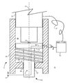
図1は、本開示の教示による、多層構造の層を評価するための例示的な装置およびシステムの部分断面平面図である。本明細書で使用するとき、「例示的な」という用語は例を表し、必ずしも理想的なものを表すわけではない。図1では、多層構造の層間ギャップを評価するための装置10は、検知ユニット12、位置決めユニット14および制御ユニット16を含むことができる。
FIG. 1 is a partial cross-sectional plan view of an exemplary apparatus and system for evaluating layers of a multi-layer structure in accordance with the teachings of the present disclosure. As used herein, the term “exemplary” represents an example and does not necessarily represent an ideal. In FIG. 1, an
位置決めユニット14は、(図1の断面に示す)位置決めフレーム20および移動ユニット22を含むことができる。位置決めフレーム20は、くぼみ26と連通する開口部24をもたらすことができる。開口部24およびくぼみ26は、軸27のまわりに実質的に対称に位置付けることができる。
The
検知ユニット12は、センサ担体32によって取り付けられたセンサユニット30を含むことができる。センサ担体32は、開口部24の中に摺動するように受け入れられ、移動ユニット22に接して支えることができる。ベアリング要素34は、移動ユニット22とセンサ担体32の間の実質的にすべての接触部をもたらすことができる。限定ではなく例として、ベアリング要素34を、移動ユニット22およびセンサ担体32の一方と入れ子式に係合されたボールベアリングとして実現すること、またはベアリング要素34を、移動ユニット22およびセンサ担体32の一方から延びる一体成形された突起として実現することが可能である。センサユニット30は、限定ではなく例として、電気接続導体36を介するなどして制御ユニット16と結合することができる。制御ユニット16は、限定ではなく例として、電気接続導体37を介するなどして移動ユニット22と結合することもできる。制御ユニット16は、センサユニット30に電気信号を供給することができる。代替の構成において、制御ユニット16は、移動ユニット22の移動中、センサユニット30に電気信号を供給することができる。電気信号は渦電流とすることができる。センサユニット30は、渦電流コイルユニットとして実現することができる。そうした渦電流コイルユニットは、センサユニット設計の技術分野の技術者には知られており、したがって、図1には詳しく図示していない。
The
センサ担体32の肩部33と、位置決めフレーム20に関連付けられた止め部35との間に、バイアス部材38を配置することができる。止め部35は、限定ではなく例として、くぼみ26の中に一体成形すること、くぼみ26の中に取り付けること、あるいは実質的に動かないように配置してバイアス部材38用の止め部をもたらすことが可能である。バイアス部材38は、センサ担体32を静止状態の配向にするように位置付けることができる。図1に図示する例示的な実施形態では、センサユニット30が位置決めフレーム20を超える延長部「e」を減少させるために、バイアス部材38が、センサ担体32を図1の上方に押し進める螺旋状の圧縮ばねとして実現されていることを理解することができる。
A
移動ユニット22は、限定ではなく例として、深さゲージまたはマイクロメータユニットとして実現することができる。センサユニット30による延長部「e」を増大させる形でセンサ担体32を実質的に軸27に沿って進めるように、移動ユニット22を、くぼみ26の中でバイアスユニット38によって与えられるバイアス力に逆らって進ませることができる。位置決めユニット22、センサユニット30および多層構造の間の相互作用に関する詳細について、図2と共にさらに詳しく記載する。
The moving
図2は、多層構造の層を評価するための本開示の使用を図示する概略図である。図2では、概して図1と共に記載したように構成された装置10が、多層構造40を評価するように取り付けられた配向で図示されている。
FIG. 2 is a schematic diagram illustrating the use of the present disclosure for evaluating layers of a multi-layer structure. In FIG. 2, the
多層構造40は、頂面41から深さd1だけ延びる第1の層42を含むことができる。第2の層44は、頂面41からの距離d2と距離d3の間に延びることができる。第3の層46は、頂面41からの距離d4と距離d5の間に延びることができる。第4の層48は、頂面41からの距離d6と距離d7の間に延びることができる。
The
層42、44は、頂面41からの距離d1と距離d2の間にギャップ43を設けることができる。層44、46は、頂面41からの距離d3と距離d4の間に中間層45を設けることができる。層46、48は、頂面41からの距離d5と距離d6の間に中間層47を設けることができる。中間層45、47は、隣接する層44、46、48とは異なる材料で実現することができる。中間層45、47および層44、46、48はそれぞれ、異なる材料で実現することができる。
多層構造40は、実質的に軸52のまわりに位置付けられた開口部50をもたらすことができる。したがって、層44、46、48は、軸52を横切って略整列した複数の縁部をもたらすことができる。複数の縁部は、実質的に軸52に対して交差するように配置して位置合わせすることができる。
The
多層構造40の評価を実行するために、ユーザは、センサユニット54を軸52に略平行に矢印56で表す方向に移動させて、層42からの延長部eを変動させるように、装置10に関連付けられた移動ユニット(図2には見られず、図1の移動ユニット22を参照)を進めることができる。
To perform the evaluation of the
センサユニット54は、多層構造40を横断するように移動させることができるため、センサユニット54によって検知される異なる特性を示す異なる材料に隣接するように位置付けることが可能である。限定ではなく例として、センサユニット54は、制御ユニット(図2には見られず、図1の制御ユニット16を参照)と協働して、インピーダンスの差を測定するように構成することができる。この配置は、センサユニット54を実質的に、ブリッジの少なくとも一部が評価される材料に隣接する、一種のホイートストンブリッジとして構成することによって行うことができる。ホイートストンブリッジを使用し、一部が未知のインピーダンスを含むブリッジ回路の2つの部分または脚部を釣り合わせることによって、未知の電気抵抗またはインピーダンスを測定することができる。ここでは、そうしたホイートストンブリッジの詳細は記載しないが、センサ設計の技術分野の技術者の理解の範囲内である。
Since the
センサユニット54は開口部50を介して多層構造40を横断するため、センサユニット54が層42、44、46、48、ギャップ43および中間層45、47のそれぞれを通過するとき、センサユニット54によってインピーダンスの変化を検知することができる。センサユニット54によって検知されたインピーダンスが変動するとき、装置10がセンサユニット54を開口部50の中に延ばしている深さに注目することによって、各層42、44、46、48、ギャップ43および各中間層45、47の厚さを確かめることができる。
The
センサユニット54は、限定ではなく他の例として、磁束または静電容量など、インピーダンス以外の別のパラメータを検知するように構成することができる。限定ではなく例として、実質的に軸52に平行な面に沿って得られるセンサユニット54の断面などの大きさが、センサユニット54によって決定可能とすることができる変化の分解能に影響を及ぼすことがある。断面が小さくなると、上面41からの距離d1における層44の材料からエアギャップ43への移行など、測定されるパラメータの変化が生じる得る場所をより細かく識別可能にすることができる場合がある。
The
センサ設計の技術分野の技術者は、評価のために、多層構造40を横断する開口部の内側の周囲縁部ではなく多層構造40の露出した縁部がもたらされる状況でも、装置10が実質的に図2と共に記載したように動作可能であることを理解することができる。
Those skilled in the art of sensor design may substantially evaluate the
図3は、開口部のまわりの異なるクロックポジションで多層構造の層を評価するための、本開示の使用を図示する概略図である。図3において、多層構造60は、エアギャップ63によって隔てられた材料層62、64を含むことができる。軸72のまわりで実質的に対称である開口部71が、多層構造60を横断することができる。
FIG. 3 is a schematic diagram illustrating the use of the present disclosure to evaluate layers of a multi-layer structure at different clock positions around an opening. In FIG. 3, the
装置10と実質的に同様に構成された装置(図3には見られず、図1および2を参照)を、開口部50に関して図2に図示した取り付けと同様の形で開口部71に取り付けることができる。概して図2と共に記載したように、挿入された装置10によって一連の評価を実施することができる。しかしながら、エアギャップ63の延長部についてより完全な評価を得るために、複数の連続した評価を実施することができる。そうしたより完全な評価はおそらく、開口部71の外周付近の複数の位置で、インピーダンスなどの電気的なパラメータに関する一連の評価の読み取りを実施することによって実行することができる。限定ではなく例として、12時の位置72で一連の評価の読み取りを実施することができる。12時の位置72での評価が完了した後、3時の位置74など他のクロックポジションで一連の評価の読み取りを実施することができるように、装置10を回転させてもよい。あるいは、3時の位置74の評価が可能になるように、移動ユニット22または検知ユニット12など装置10の一部を回転させてもよい。3時の位置74での評価が完了した後、8時の位置76など他のクロックポジションで一連の評価の読み取りを実施することができるように、装置10を回転させてもよい。開口部71のまわりで、そうした異なるクロックポジションにおける一連の評価を実施することによって、図3に示すケースのように、開口部71のまわりでエアギャップ63の層62、64からの間隔が均一でないかどうかを確かめることを可能にすることができる。
A device configured substantially similar to the device 10 (not seen in FIG. 3, see FIGS. 1 and 2) is attached to the opening 71 in a manner similar to that shown in FIG. be able to. A series of evaluations can be performed by the inserted
図4は、本開示の方法を示す流れ図である。図4では、多層構造において層間ギャップを評価して前記評価を表すマップを生成する方法100は、開始位置102から始まる。多層構造は、軸を横切って略整列した複数の縁部を呈する。
FIG. 4 is a flow diagram illustrating the method of the present disclosure. In FIG. 4, a
方法100は、続いて、順不同に、(1)ブロック104によって示すように、少なくとも1つのパラメータを検知するように構成された検知ユニットを提供すること、(2)ブロック106によって示すように、検知ユニットと結合され、検知ユニットを軸に略平行に移動させるように構成することができる位置決めユニットを提供すること、ならびに(3)ブロック108によって示すように、位置決めユニットおよび検知ユニットの少なくとも1つと結合された制御ユニットを提供することを行う。
The
方法100は、続いて、ブロック110によって示すように、制御ユニットを、検知ユニットに電気信号を供給するように動作させる。あるいは、電気信号は、検知ユニットの移動中に検知ユニットに供給されてもよい。
The
方法100は、続いて、ブロック112によって示すように、検知ユニットが複数の縁部を過ぎて移動するとき、制御ユニットを、少なくとも1つのパラメータの変化を監視するように動作させる。
The
方法100は、続いて、ブロック114によって示すように、制御ユニットを、少なくとも1つのパラメータの変化を使用して評価を行うように動作させる。
The
方法100は、続いて、ブロック116によって示すように、評価を使用してマップを生成する。マップは、図形表示の形、図形表示の表形式の表現、またはユーザに有用な他の形式とすることができる。マップは、後で使用または評価するために、記憶装置に記憶させることができる。
The
方法100は、終了位置118で終わる。
示された詳細な図面および特定の例は、本開示の好ましい実施形態を記述するが、説明のためのものにすぎず、本開示の装置および方法は、開示されたとおりの細部および条件に限定されず、以下の特許請求の範囲によって定められる本開示の趣旨から逸脱することなく、細部および条件に様々な変更を加えることが可能であることを理解されたい。
また、本願は以下に記載する態様を含む。
(態様1)
軸を横切って略整列した複数の縁部を呈する多層構造の層間ギャップを評価するための装置であって、
(a)少なくとも1つのパラメータを検知するように構成された検知ユニット、
(b)前記検知ユニットと結合されて、前記検知ユニットを前記軸に略沿って移動させるように構成された位置決めユニット、ならびに
(c)前記位置決めユニットおよび前記検知ユニットの少なくとも1つと結合された制御ユニット
を備え、前記制御ユニットが、前記検知ユニットに電気信号を供給し、前記検知ユニットが前記複数の縁部を過ぎて移動するときに前記少なくとも1つのパラメータの変化を監視し、かつ前記少なくとも1つのパラメータの前記変化を使用して前記評価を行う装置。
(態様2)
前記複数の縁部が、前記軸と略平行な前記多層構造の少なくとも一部を横断する開口部を実質的に囲んでいる、態様1に記載の多層構造の層間ギャップを評価するための装置。
(態様3)
前記位置決めユニットが、前記位置決めユニットによる前記検知ユニットの変位を示すように構成されており、前記変位が、前記評価の際に前記制御ユニットによって使用される、態様1に記載の多層構造の層間ギャップを評価するための装置。
(態様4)
前記位置決めユニットがマイクロメータユニットとして実現されている、態様1に記載の多層構造の層間ギャップを評価するための装置。
(態様5)
前記検知ユニットが渦電流コイルユニットを含んでいる、態様1に記載の多層構造の層間ギャップを評価するための装置。
(態様6)
前記少なくとも1つのパラメータが、前記渦電流コイルユニットが受けるインピーダンスである、態様5に記載の多層構造の層間ギャップを評価するための装置。
(態様7)
前記位置決めユニットが、前記位置決めユニットによる前記検知ユニットの変位を示すように構成されており、前記変位が、前記評価の際に前記制御ユニットによって使用される、態様2に記載の多層構造の層間ギャップを評価するための装置。
(態様8)
前記検知ユニットが渦電流コイルユニットを含んでいる、態様7に記載の多層構造の層間ギャップを評価するための装置。
(態様9)
前記少なくとも1つのパラメータが、前記渦電流コイルユニットが受けるインピーダンスである、態様8に記載の多層構造の層間ギャップを評価するための装置。
(態様10)
多層構造の軸に略沿って異なる材料層の厚さを決定するためのシステムであって、前記厚さが、実質的に前記軸と交差するように位置合わせされた複数の縁部によって画定されるシステムにおいて、
(a)少なくとも1つの電磁パラメータを検知するように構成された電磁センサユニット、
(b)前記センサユニットと結合されて、前記センサユニットを前記軸に略沿って移動させる位置決めユニット、ならびに
(c)前記センサユニットおよび前記位置決めユニットの少なくとも1つと結合された監視ユニットであって、前記センサユニットに電気入力信号を供給し、前記センサユニットが前記軸に沿って前記複数の縁部を過ぎて移動するときに前記センサユニットから前記少なくとも1つの電磁パラメータの変化の示度を受け取り、前記少なくとも1つの電磁パラメータの前記変化を使用して前記決定を行う監視ユニット
を備えるシステム。
(態様11)
前記複数の縁部が、前記軸と略平行な前記多層構造の少なくとも一部を横断する開口部を実質的に囲んでいる、態様10に記載の多層構造の軸に略沿って異なる材料層の厚さを決定するためのシステム。
(態様12)
前記位置決めユニットが、前記位置決めユニットによる前記検知ユニットの変位を示すように構成されており、前記変位が、前記決定の際に前記監視ユニットによって使用される、態様11に記載の多層構造の軸に略沿って異なる材料層の厚さを決定するためのシステム。
(態様13)
前記位置決めユニットがマイクロメータユニットとして実現される、態様12に記載の多層構造の軸に略沿って異なる材料層の厚さを決定するためのシステム。
(態様14)
前記センサユニットが渦電流コイルユニットを含んでいる、態様13に記載の多層構造の軸に略沿って異なる材料層の厚さを決定するためのシステム。
(態様15)
前記少なくとも1つの電磁パラメータが、前記渦電流コイルユニットが受けるインピーダンスである、態様14に記載の多層構造の軸に略沿って異なる材料層の厚さを決定するためのシステム。
(態様16)
軸を横切って略整列した複数の縁部を呈する多層構造において層間ギャップを評価し、前記評価を表すマップを生成するための方法であって、
(a)順不同で、
(1)少なくとも1つのパラメータを検知するように構成された検知ユニットを提供し、
(2)前記検知ユニットと結合されて、前記検知ユニットを前記軸に略平行に移動させるように構成された位置決めユニットを提供し、
(3)前記位置決めユニットおよび前記検知ユニットの少なくとも1つと結合された制御ユニットを提供することと
(b)前記制御ユニットを、前記検知ユニットに電気信号を供給するように動作させることと、
(c)前記検知ユニットが前記複数の縁部を過ぎて移動するとき、前記制御ユニットを、前記少なくとも1つのパラメータの変化を監視するように動作させることと、
(d)前記制御ユニットを、前記少なくとも1つのパラメータの前記変化を使用して前記評価を行うように動作させることと、
(e)前記評価を使用して前記マップを生成することと
を含む方法。
(態様17)
前記複数の縁部が、前記軸と略平行な前記多層構造の少なくとも一部を横断する開口部を実質的に囲む、態様16に記載の多層構造の層間ギャップを評価するための方法。
(態様18)
前記位置決めユニットが、前記位置決めユニットによる前記検知ユニットの変位を示すように配置されたマイクロメータユニットであり、前記変位を、前記評価の際に前記制御ユニットが使用する、態様17に記載の多層構造の層間ギャップを評価するための方法。
(態様19)
前記検知ユニットが渦電流コイルユニットを含む、態様18に記載の多層構造の層間ギャップを評価するための方法。
(態様20)
前記少なくとも1つのパラメータが、前記渦電流コイルユニットが受けるインピーダンスである、態様19に記載の多層構造の層間ギャップを評価するための方法。
The detailed drawings shown and specific examples describe preferred embodiments of the present disclosure, but are intended to be illustrative only and the apparatus and methods of the present disclosure are limited to the details and conditions as disclosed. However, it should be understood that various changes and modifications can be made in the details and conditions without departing from the spirit of the disclosure as defined by the following claims.
Moreover, this application contains the aspect described below.
(Aspect 1)
An apparatus for evaluating an interlayer gap in a multilayer structure exhibiting a plurality of edges generally aligned across an axis,
(A) a sensing unit configured to sense at least one parameter;
(B) a positioning unit coupled to the detection unit and configured to move the detection unit substantially along the axis; and
(C) a control unit coupled to at least one of the positioning unit and the detection unit
The control unit supplies an electrical signal to the sensing unit, monitors the change of the at least one parameter as the sensing unit moves past the plurality of edges, and the at least one An apparatus for performing the evaluation using the change in parameter.
(Aspect 2)
The apparatus for evaluating an interlayer gap in a multilayer structure according to aspect 1, wherein the plurality of edges substantially surround an opening that traverses at least a portion of the multilayer structure substantially parallel to the axis.
(Aspect 3)
The interlayer gap of the multilayer structure according to aspect 1, wherein the positioning unit is configured to indicate a displacement of the detection unit by the positioning unit, and the displacement is used by the control unit during the evaluation. Device for evaluating.
(Aspect 4)
The apparatus for evaluating an interlayer gap of a multilayer structure according to aspect 1, wherein the positioning unit is realized as a micrometer unit.
(Aspect 5)
The apparatus for evaluating an interlayer gap of a multilayer structure according to aspect 1, wherein the sensing unit includes an eddy current coil unit.
(Aspect 6)
The apparatus for evaluating an interlayer gap of a multilayer structure according to aspect 5, wherein the at least one parameter is an impedance experienced by the eddy current coil unit.
(Aspect 7)
The interlayer gap of the multilayer structure according to aspect 2, wherein the positioning unit is configured to indicate a displacement of the detection unit by the positioning unit, and the displacement is used by the control unit during the evaluation. Device for evaluating.
(Aspect 8)
The apparatus for evaluating an interlayer gap of a multilayer structure according to aspect 7, wherein the detection unit includes an eddy current coil unit.
(Aspect 9)
The apparatus for evaluating an interlayer gap of a multilayer structure according to aspect 8, wherein the at least one parameter is an impedance experienced by the eddy current coil unit.
(Aspect 10)
A system for determining thicknesses of different material layers substantially along an axis of a multilayer structure, wherein the thickness is defined by a plurality of edges aligned to substantially intersect the axis. In the system
(A) an electromagnetic sensor unit configured to detect at least one electromagnetic parameter;
(B) a positioning unit coupled to the sensor unit to move the sensor unit substantially along the axis; and
(C) a monitoring unit coupled to at least one of the sensor unit and the positioning unit for supplying an electrical input signal to the sensor unit, the sensor unit passing the plurality of edges along the axis; A monitoring unit that receives an indication of a change in the at least one electromagnetic parameter from the sensor unit as it travels and uses the change in the at least one electromagnetic parameter to make the determination
A system comprising:
(Aspect 11)
11. The plurality of edges of different material layers substantially along an axis of the multilayer structure according to
(Aspect 12)
12. The multi-layered shaft according to aspect 11, wherein the positioning unit is configured to indicate a displacement of the detection unit by the positioning unit, and the displacement is used by the monitoring unit in the determination. A system for determining the thickness of different material layers substantially along.
(Aspect 13)
The system for determining different material layer thicknesses substantially along the axis of the multilayer structure according to
(Aspect 14)
14. A system for determining thicknesses of different material layers substantially along an axis of a multilayer structure according to aspect 13, wherein the sensor unit comprises an eddy current coil unit.
(Aspect 15)
15. A system for determining different material layer thicknesses substantially along an axis of a multilayer structure according to
(Aspect 16)
A method for evaluating interlayer gaps in a multilayer structure exhibiting a plurality of edges generally aligned across an axis and generating a map representing said evaluations,
(A) out of order,
(1) providing a sensing unit configured to sense at least one parameter;
(2) providing a positioning unit coupled to the detection unit and configured to move the detection unit substantially parallel to the axis;
(3) providing a control unit coupled to at least one of the positioning unit and the detection unit;
(B) operating the control unit to supply an electrical signal to the detection unit;
(C) operating the control unit to monitor a change in the at least one parameter as the sensing unit moves past the plurality of edges;
(D) operating the control unit to perform the evaluation using the change in the at least one parameter;
(E) generating the map using the evaluation;
Including methods.
(Aspect 17)
The method for evaluating an interlayer gap of a multilayer structure according to
(Aspect 18)
The multilayer structure according to aspect 17, wherein the positioning unit is a micrometer unit arranged to indicate a displacement of the detection unit by the positioning unit, and the control unit uses the displacement in the evaluation. Method for evaluating the interlayer gap of
(Aspect 19)
The method for evaluating an interlayer gap of a multilayer structure according to aspect 18, wherein the sensing unit comprises an eddy current coil unit.
(Aspect 20)
The method for evaluating an interlayer gap of a multilayer structure according to aspect 19, wherein the at least one parameter is an impedance experienced by the eddy current coil unit.
10 装置
12 検知ユニット
14 位置決めユニット
16 制御ユニット
20 位置決めフレーム
22 移動ユニット
24 開口部
26 くぼみ
27 軸
30 センサユニット
32 センサ担体
33 肩部
34 ベアリング要素
35 止め部
36 電気接続導体
37 電気接続導体
38 バイアス部材
e 延長部
40 多層構造
41 頂面
42、44、46、48 層
43 エアギャップ
45、47 中間層
50 開口部
52 軸
54 センサユニット
60 多層構造
62、64 材料層
63 エアギャップ
71 開口部
72 軸
72 12時の位置
74 3時の位置
76 8時の位置
DESCRIPTION OF
Claims (7)
(a)少なくとも1つのパラメータを検知するように構成された検知ユニット、
(b)前記検知ユニットと結合されている位置決めユニットであって、
前記多層構造と結合されるときに、位置フレームが実質的に前記開口部を囲み、前記検知ユニットが前記軸に実質的に同軸に整列されるように、前記多層構造と選択的に結合されている位置フレームを含み、前記検知ユニットを前記検知ユニットと前記多層構造との間にすき間がある前記開口部を通して前記軸に略沿って移動させ、前記軸の周りに前記検知ユニットを回転させるように構成された位置決めユニット、ならびに
(c)前記位置決めユニットおよび前記検知ユニットの少なくとも1つと結合された制御ユニットを備え、前記制御ユニットが、前記検知ユニットに電気信号を供給し、前記検知ユニットが前記複数の縁部を過ぎて移動及び前記開口部内での回転するときに前記少なくとも1つのパラメータの変化を監視し、かつ前記少なくとも1つのパラメータの前記変化を使用して前記多層構造の隣接層間の距離及び前記多層構造の層の厚さの前記評価を行う装置。 Across the axis caused a multiple edge portions substantially aligned, at least partially surrounds the opening across the apparatus for evaluating the interlayer gap of the multilayer structure is substantially parallel to the axis of the multi-layer structure Because
(A) a sensing unit configured to sense at least one parameter;
(B) a positioning unit coupled to the detection unit,
When coupled with the multilayer structure, the position frame is selectively coupled with the multilayer structure such that the position frame substantially surrounds the opening and the sensing unit is aligned substantially coaxially with the axis. includes position frames are moves substantially along the axis through the opening there is a gap between the sensing unit and the sensing unit and the multi-layer structure, so that by rotating the detection unit around the axis (C) a control unit coupled to at least one of the positioning unit and the detection unit, wherein the control unit supplies an electrical signal to the detection unit, and the detection unit Monitoring the change of the at least one parameter as it moves past a plurality of edges and rotates within the opening ; and An apparatus for performing the evaluation of the distance between adjacent layers of the multilayer structure and the thickness of the layers of the multilayer structure using the change of at least one parameter.
(a)少なくとも1つの電磁パラメータを検知するように構成された電磁センサユニット、
(b)前記センサユニットと結合されている位置決めユニットであって、前記多層構造と結合されるときに、位置フレームが実質的に前記開口部を囲み、前記センサユニットが前記軸に実質的に同軸に整列されるように、前記多層構造と選択的に結合されている位置フレームを含み、前記センサユニットを前記センサユニットと前記多層構造との間にすき間がある前記開口部を通して前記軸に略沿って移動させ、前記軸の周りに前記センサユニットを回転させる位置決めユニット、ならびに
(c)前記センサユニットおよび前記位置決めユニットの少なくとも1つと結合された監視ユニットであって、前記センサユニットに電気入力信号を供給し、前記センサユニットが前記軸に沿って前記複数の縁部を過ぎて移動及び前記開口部内での回転するときに前記センサユニットから前記少なくとも1つの電磁パラメータの変化の示度を受け取り、前記少なくとも1つの電磁パラメータの前記変化を使用して前記多層構造の隣接する異なる材料層間の距離及び前記多層構造の異なる材料層の厚さの前記決定を行う監視ユニットを備えるシステム。 A system for determining thicknesses of different material layers substantially along an axis of a multilayer structure, wherein the thicknesses are aligned to substantially intersect the axis and are substantially parallel to the axis In a system defined by a plurality of edges substantially surrounding an opening that traverses at least a portion of a multilayer structure ,
(A) an electromagnetic sensor unit configured to detect at least one electromagnetic parameter;
(B) a positioning unit coupled to the sensor unit, wherein when coupled to the multi-layer structure, a position frame substantially surrounds the opening and the sensor unit is substantially coaxial with the axis. A position frame that is selectively coupled to the multilayer structure so that the sensor unit is substantially aligned with the axis through the opening with a gap between the sensor unit and the multilayer structure. move Te, positioning unit Ru rotating the sensor unit about the axis, and (c) at least one combined monitoring unit of the sensor unit and the positioning unit, an electrical input signal to the sensor unit The sensor unit moves past the edges along the axis and rotates within the opening. When receiving an indication of a change in the at least one electromagnetic parameter from the sensor unit, and using the change in the at least one electromagnetic parameter, the distance between adjacent different material layers of the multilayer structure and of the multilayer structure A system comprising a monitoring unit for making said determination of the thickness of different material layers .
(a)順不同で、
(1)少なくとも1つのパラメータを検知するように構成された検知ユニットを提供し、
(2)前記検知ユニットと結合されている位置決めユニットであって、前記多層構造と結合される時に、前記位置決めユニットの位置フレームが実質的に前記開口部を囲み、前記検知ユニットが前記軸に実質的に同軸に整列されるように、前記多層構造と選択的に結合され、前記検知ユニットを前記検知ユニットと前記多層構造との間のすき間のある前記開口部を通して前記軸に略平行に移動させ、前記軸の周りに前記検知ユニットを回転させるように構成された位置決めユニットを提供し、
(3)前記位置決めユニットおよび前記検知ユニットの少なくとも1つと結合された制御ユニットを提供することと
(b)前記制御ユニットを、前記検知ユニットに電気信号を供給するように動作させることと、
(c)前記検知ユニットが前記複数の縁部を過ぎて移動及び前記開口部内での回転するとき、前記制御ユニットを、前記少なくとも1つのパラメータの変化を監視するように動作させることと、
(d)前記制御ユニットを、前記少なくとも1つのパラメータの前記変化を使用して前記多層構造の隣接層間の距離と前記多層構造の層の厚さの前記評価を行うように動作させることと、
(e)前記評価を使用して前記マップを生成することと
を含む方法。 Across the axis, to evaluate the interlayer gap in the multilayer structure exhibiting a plurality of edges and substantially aligned surrounds substantially an opening that traverses at least a portion of substantially parallel multi-layer structure and said shaft, said evaluation A method for generating a map representing
(A) out of order,
(1) providing a sensing unit configured to sense at least one parameter;
(2) a said sensing positioning unit that is coupled with the unit, when combined with the multilayer structure, position the frame of the positioning unit is essentially surrounding the opening, wherein the detection unit substantially on said axis Selectively coupled to the multi-layer structure so as to be coaxially aligned and move the sensing unit substantially parallel to the axis through the opening with a gap between the sensing unit and the multi-layer structure. provides a positioning unit configured to so that rotating the detection unit about the axis,
(3) providing a control unit coupled to at least one of the positioning unit and the detection unit; (b) operating the control unit to supply an electrical signal to the detection unit;
(C) operating the control unit to monitor a change in the at least one parameter as the sensing unit moves past the plurality of edges and rotates within the opening ;
(D) operating the control unit to perform the evaluation of the distance between adjacent layers of the multilayer structure and the thickness of the layers of the multilayer structure using the change of the at least one parameter;
(E) generating the map using the evaluation.
Applications Claiming Priority (2)
| Application Number | Priority Date | Filing Date | Title |
|---|---|---|---|
| US12/965,356 US8903680B2 (en) | 2010-12-10 | 2010-12-10 | Apparatus and method for evaluating layers in a multi-layer structure |
| US12/965,356 | 2010-12-10 |
Publications (3)
| Publication Number | Publication Date |
|---|---|
| JP2012127948A JP2012127948A (en) | 2012-07-05 |
| JP2012127948A5 JP2012127948A5 (en) | 2015-01-22 |
| JP5954726B2 true JP5954726B2 (en) | 2016-07-20 |
Family
ID=45560312
Family Applications (1)
| Application Number | Title | Priority Date | Filing Date |
|---|---|---|---|
| JP2011264460A Active JP5954726B2 (en) | 2010-12-10 | 2011-12-02 | Apparatus and method for evaluating layers in a multilayer structure |
Country Status (5)
| Country | Link |
|---|---|
| US (1) | US8903680B2 (en) |
| JP (1) | JP5954726B2 (en) |
| CN (1) | CN102607402B (en) |
| CA (1) | CA2755744C (en) |
| GB (1) | GB2486347B (en) |
Families Citing this family (4)
| Publication number | Priority date | Publication date | Assignee | Title |
|---|---|---|---|---|
| CN104833298B (en) * | 2014-02-12 | 2018-02-09 | 鸿发国际科技股份有限公司 | Paper sheet thickness detection device and its paper sheet thickness detection method |
| US11148070B2 (en) * | 2018-03-07 | 2021-10-19 | Palo Alto Research Center Incorporated | Systems and methods of nanofiltration using graphene oxide |
| CN110006996B (en) * | 2019-04-22 | 2021-11-30 | 葫芦岛探克科技有限公司 | Ultrasonic thickness measurement method for metal composite material and application of interlayer interface in ultrasonic thickness measurement |
| CN111458415B (en) * | 2020-04-13 | 2023-07-18 | 润电能源科学技术有限公司 | Method for detecting coupling state of ultrasonic phased array transducer and workpiece to be detected |
Family Cites Families (23)
| Publication number | Priority date | Publication date | Assignee | Title |
|---|---|---|---|---|
| US3693075A (en) * | 1969-11-15 | 1972-09-19 | Forster F M O | Eddy current system for testing tubes for defects,eccentricity,and wall thickness |
| JPS5672303A (en) * | 1979-11-15 | 1981-06-16 | Nuclear Fuel Ind Ltd | Measuring method of displacement of fuel rod of noncontact type |
| FR2494837A1 (en) | 1980-11-26 | 1982-05-28 | Commissariat Energie Atomique | DEVICE FOR CONTROLLING THE DIMENSIONS AND THE SPACING OF RIGID PARTS DISPOSED IN BEAM |
| FR2585868B1 (en) * | 1985-08-02 | 1987-11-27 | Framatome Sa | DEVICE FOR MONITORING THE ALIGNMENT IN THE VERTICAL DIRECTION OF THE UPPER AND LOWER INTERNAL EQUIPMENT OF A PRESSURE WATER NUCLEAR REACTOR. |
| US4645634A (en) | 1983-12-19 | 1987-02-24 | The Babcock & Wilcox Company | Apparatus for measuring the pitch between adjacent rods in a nuclear fuel assembly |
| DE3542200A1 (en) | 1985-11-29 | 1987-06-04 | Bbc Reaktor Gmbh | METHOD FOR CHECKING THE DIMENSIONS OF A FUEL ELEMENT FOR CORE REACTORS |
| JPH0636046B2 (en) * | 1988-06-08 | 1994-05-11 | 株式会社日立製作所 | Fuel assemblies, fuel spacers, and initial reactor core of reactor |
| US4876506A (en) * | 1988-06-13 | 1989-10-24 | Westinghouse Electric Corp. | Apparatus and method for inspecting the profile of the inner wall of a tube employing a wall follower and an eddy current probe |
| FR2656415B1 (en) * | 1989-12-27 | 1993-04-09 | Framatome Sa | METHOD AND DEVICE FOR SIMULTANEOUSLY MEASURING DISTANCE BETWEEN METAL TUBES AND OXIDE THICKNESS ON TUBES. |
| JPH0442002A (en) * | 1990-06-07 | 1992-02-12 | Nuclear Fuel Ind Ltd | Fuel-rod-gap measuring apparatus |
| FR2669843B1 (en) * | 1990-11-29 | 1995-01-20 | Lorraine Laminage | DEVICE FOR DETECTING LONGITUDINAL CRACKS ON SLABS, ESPECIALLY ON STEEL SLAMS. |
| US5371462A (en) * | 1993-03-19 | 1994-12-06 | General Electric Company | Eddy current inspection method employing a probe array with test and reference data acquisition and signal processing |
| US5341678A (en) * | 1993-05-12 | 1994-08-30 | General Electric Company | Method for determining thickness of ferromagnetic material deposition on nuclear fuel rods |
| JPH09318784A (en) * | 1996-05-31 | 1997-12-12 | Mitsubishi Heavy Ind Ltd | Fuel rod gap measuring device for nuclear fuel assembly |
| US5744952A (en) * | 1997-02-25 | 1998-04-28 | Mcdermott Technology, Inc. | Eddy current measurement of tube element spacing |
| JP4328066B2 (en) * | 2002-07-26 | 2009-09-09 | コーア株式会社 | Film thickness inspection apparatus and film thickness inspection method |
| US7314075B2 (en) * | 2003-04-04 | 2008-01-01 | Nisca Corporation | Adhesive dispensing apparatus and image forming apparatus |
| DE102004034083A1 (en) * | 2004-07-15 | 2006-02-09 | Robert Bosch Gmbh | Method for the non-contact determination of a layer thickness by resistance and inductance measurement of a sensor coil |
| DE102004034081A1 (en) * | 2004-07-15 | 2006-02-09 | Robert Bosch Gmbh | Method for the contactless determination of a thickness of a layer of electrically conductive material |
| JP2006349377A (en) * | 2005-06-13 | 2006-12-28 | Shinko Electric Co Ltd | Two-degree-of-freedom sensor |
| DE102005054593B4 (en) * | 2005-11-14 | 2018-04-26 | Immobiliengesellschaft Helmut Fischer Gmbh & Co. Kg | Measuring probe for measuring the thickness of thin layers |
| CN101074861B (en) * | 2007-06-27 | 2011-02-02 | 力帆实业(集团)股份有限公司 | Profiling comb assembly |
| JP4803323B2 (en) * | 2010-02-25 | 2011-10-26 | Jfeスチール株式会社 | Wire rope pitch measuring method, wire rope pitch measuring device, and wire rope manufacturing method |
-
2010
- 2010-12-10 US US12/965,356 patent/US8903680B2/en active Active
-
2011
- 2011-10-20 CA CA2755744A patent/CA2755744C/en active Active
- 2011-12-02 JP JP2011264460A patent/JP5954726B2/en active Active
- 2011-12-09 GB GB1121319.6A patent/GB2486347B/en active Active
- 2011-12-12 CN CN201110437963.4A patent/CN102607402B/en active Active
Also Published As
| Publication number | Publication date |
|---|---|
| US8903680B2 (en) | 2014-12-02 |
| CN102607402A (en) | 2012-07-25 |
| GB2486347B (en) | 2016-01-27 |
| US20120150466A1 (en) | 2012-06-14 |
| GB201121319D0 (en) | 2012-01-25 |
| JP2012127948A (en) | 2012-07-05 |
| CA2755744A1 (en) | 2012-06-10 |
| CA2755744C (en) | 2016-04-12 |
| GB2486347A (en) | 2012-06-13 |
| CN102607402B (en) | 2016-05-25 |
Similar Documents
| Publication | Publication Date | Title |
|---|---|---|
| US8274276B2 (en) | System and method for the non-destructive testing of elongate bodies and their weldbond joints | |
| CA2711552C (en) | Sensor assembly | |
| JP5954726B2 (en) | Apparatus and method for evaluating layers in a multilayer structure | |
| US9464979B2 (en) | Monitoring a conductive fluid conduit | |
| US8717012B2 (en) | Eddy current probe for surface and sub-surface inspection | |
| CA2815627A1 (en) | Inspection apparatus and method | |
| US20140091785A1 (en) | Target clearance measurement device | |
| HRP20240757T1 (en) | Pipeline condition detecting apparatus and method | |
| KR102167975B1 (en) | Magnetic shipboard damage evaluation method and damage evaluation device | |
| US7576532B2 (en) | Motion transducer for motion related to the direction of the axis of an eddy-current displacement sensor | |
| JP3197515U (en) | Liquid level sensor | |
| US7578072B2 (en) | Digital indicator and method for using the digital indicator | |
| JP2012127948A5 (en) | ||
| CN103076578B (en) | Magnetic field intensity detection device for anisotropic magneto resistance structure | |
| CN100504306C (en) | AMR sensor element for angle measurement | |
| JP6779194B2 (en) | Reinforcing bar counting device, reinforced concrete column discrimination method and reinforced concrete column discrimination system | |
| JP2011158438A (en) | Method for inspecting reinforcement bar corrosion in concrete pole | |
| CN111197995B (en) | Proximity sensing system for performing component compatibility tests | |
| JP3942165B2 (en) | Eddy current testing probe | |
| JP2015078942A (en) | Leakage magnetic flux flaw detector | |
| KR101192812B1 (en) | Apparatus for detecting unsuitable tires with an exposed cord | |
| KR101411339B1 (en) | Safety diagnosis equipment for main-cable of suspension bridges | |
| KR101288105B1 (en) | Apparatus for measuring | |
| KR20090119807A (en) | Probe structure of eddy current tester for cylindrical steel pipes | |
| JP2014006121A (en) | Distance sensor |
Legal Events
| Date | Code | Title | Description |
|---|---|---|---|
| A521 | Request for written amendment filed |
Free format text: JAPANESE INTERMEDIATE CODE: A523 Effective date: 20141201 |
|
| A621 | Written request for application examination |
Free format text: JAPANESE INTERMEDIATE CODE: A621 Effective date: 20141201 |
|
| A977 | Report on retrieval |
Free format text: JAPANESE INTERMEDIATE CODE: A971007 Effective date: 20150928 |
|
| A131 | Notification of reasons for refusal |
Free format text: JAPANESE INTERMEDIATE CODE: A131 Effective date: 20151006 |
|
| A521 | Request for written amendment filed |
Free format text: JAPANESE INTERMEDIATE CODE: A523 Effective date: 20151225 |
|
| TRDD | Decision of grant or rejection written | ||
| A01 | Written decision to grant a patent or to grant a registration (utility model) |
Free format text: JAPANESE INTERMEDIATE CODE: A01 Effective date: 20160531 |
|
| A61 | First payment of annual fees (during grant procedure) |
Free format text: JAPANESE INTERMEDIATE CODE: A61 Effective date: 20160607 |
|
| R150 | Certificate of patent or registration of utility model |
Ref document number: 5954726 Country of ref document: JP Free format text: JAPANESE INTERMEDIATE CODE: R150 |
|
| R250 | Receipt of annual fees |
Free format text: JAPANESE INTERMEDIATE CODE: R250 |
|
| R250 | Receipt of annual fees |
Free format text: JAPANESE INTERMEDIATE CODE: R250 |
|
| R250 | Receipt of annual fees |
Free format text: JAPANESE INTERMEDIATE CODE: R250 |
|
| R250 | Receipt of annual fees |
Free format text: JAPANESE INTERMEDIATE CODE: R250 |
|
| R250 | Receipt of annual fees |
Free format text: JAPANESE INTERMEDIATE CODE: R250 |
|
| R250 | Receipt of annual fees |
Free format text: JAPANESE INTERMEDIATE CODE: R250 |