JP5953786B2 - Exhaust system for multi-cylinder engine - Google Patents
Exhaust system for multi-cylinder engine Download PDFInfo
- Publication number
- JP5953786B2 JP5953786B2 JP2012023975A JP2012023975A JP5953786B2 JP 5953786 B2 JP5953786 B2 JP 5953786B2 JP 2012023975 A JP2012023975 A JP 2012023975A JP 2012023975 A JP2012023975 A JP 2012023975A JP 5953786 B2 JP5953786 B2 JP 5953786B2
- Authority
- JP
- Japan
- Prior art keywords
- exhaust
- downstream
- upstream
- cylinder
- mixing tube
- Prior art date
- Legal status (The legal status is an assumption and is not a legal conclusion. Google has not performed a legal analysis and makes no representation as to the accuracy of the status listed.)
- Expired - Fee Related
Links
Images


Description
本発明は、自動車等に搭載される多気筒エンジンの排気装置に関する。 The present invention relates to an exhaust device for a multi-cylinder engine mounted on an automobile or the like.
従来、自動車等に搭載される多気筒エンジンにおいて、トルクの向上を目的とした排気装置の開発が行なわれている。 Conventionally, in a multi-cylinder engine mounted on an automobile or the like, an exhaust device for the purpose of improving torque has been developed.
例えば、特許文献1には、排気順序が連続しない気筒の排気通路を束ねて、先細りの排気管として集合させ、この絞り部分にエゼクタ効果を持たせて、気筒間の排気干渉を防止する技術が開示されている。
For example,
多気筒エンジンにおいて、広い回転域に亘ってトルクの向上を図り、トルクのワイドレンジ化を達成するためには、例えばエンジン低速域においてエゼクタ効果が得られるように排気系を構成することが有効である。その場合、各気筒から排出された排気が混合管に噴出したときに該混合管内に発生する負圧ができるだけ大きくなるように該混合管を構成することが重要である。 In a multi-cylinder engine, in order to improve torque over a wide rotation range and achieve a wide range of torque, it is effective to configure an exhaust system so that, for example, an ejector effect can be obtained at a low engine speed range. is there. In that case, it is important to configure the mixing tube so that the negative pressure generated in the mixing tube becomes as large as possible when the exhaust discharged from each cylinder is ejected into the mixing tube.
そこで、本発明は、各気筒から排出された排気が集合する混合管内の負圧が可及的に大きくなり、エゼクタ効果が高められた多気筒エンジンの排気装置の提供を目的とする。 Accordingly, an object of the present invention is to provide an exhaust device for a multi-cylinder engine in which the negative pressure in the mixing pipe where exhaust discharged from each cylinder gathers becomes as large as possible and the ejector effect is enhanced.
前記課題を解決するために、本発明は、吸気ポートを開閉可能な吸気弁及び排気ポートを開閉可能な排気弁が備えられた複数の気筒を有する多気筒エンジンの排気装置であって、1つの気筒又は排気順序が連続しない複数の気筒の排気ポートにそれぞれ接続された複数の独立排気通路と、前記独立排気通路の各下流端部が束ねられて接続され、各独立排気通路の下流端部から噴出した排気が集合する混合管とが設けられ、少なくともエンジン低速域においては、各気筒の吸排気開弁期間が所定のオーバーラップ期間を有し、排気順序が連続する気筒間において一方の気筒のオーバーラップ期間が他方の気筒の排気開弁時期に重複するように設定され、前記混合管は、流路面積が最小の中間部位と、当該中間部位から上流側に延びて前記独立排気通路の各下流端部に接続されるとともに流路面積が上流側から下流側に向けて徐々に縮小する上流部位と、前記中間部位から下流側に延びて流路面積が上流側から下流側に向けて徐々に拡大する下流部位とを有し、前記上流部位の下流端の流路面積および前記下流部位の上流端の流路面積は、それぞれ前記中間部位の流路面積と一致しており、前記混合管の下流部位の下流端部には、内側に触媒本体を収容するケーシングが、前記混合管の下流部位の下流端部の中心と前記ケーシングの上流端の中心とが略一致するように接続され、前記中間部位から前記ケーシングまでの部分の流路面積は、下流側ほど大きくなるように設定されており、前記上流部位の流路面積の縮小率の平均値を△S1とし、前記下流部位の流路面積の拡大率の平均値を△S2としたときに、△S1>△S2となるように設定されていることを特徴とする多気筒エンジンの排気装置である(請求項1)。
In order to solve the above problems, the present invention is an exhaust system for a multi-cylinder engine having a plurality of cylinders provided with an intake valve capable of opening and closing an intake port and an exhaust valve capable of opening and closing an exhaust port. A plurality of independent exhaust passages connected to the exhaust ports of the cylinders or a plurality of cylinders whose exhaust order is not continuous and the downstream end portions of the independent exhaust passages are bundled and connected, and from the downstream end portions of the independent exhaust passages And a mixing pipe for collecting the discharged exhaust gas, and at least in the engine low speed region, the intake / exhaust valve opening period of each cylinder has a predetermined overlap period, and one cylinder has a continuous exhaust sequence. The overlap period is set to overlap the exhaust valve opening timing of the other cylinder, and the mixing pipe extends from the intermediate part to the upstream side with the intermediate part having the smallest flow path area and the independent exhaust. An upstream part connected to each downstream end of the passage and gradually reducing the flow area from the upstream side toward the downstream side, and extending from the intermediate part to the downstream side so that the flow area increases from the upstream side to the downstream side A downstream portion that gradually expands toward the upstream portion, and the flow passage area at the downstream end of the upstream portion and the flow passage area at the upstream end of the downstream portion are respectively coincident with the flow passage area of the intermediate portion, At the downstream end of the downstream portion of the mixing tube , a casing that accommodates the catalyst main body is arranged so that the center of the downstream end portion of the downstream portion of the mixing tube and the center of the upstream end of the casing substantially coincide with each other. The flow path area of the connected portion from the intermediate part to the casing is set so as to increase toward the downstream side, and an average value of the reduction ratio of the flow area at the upstream part is ΔS1, and the downstream part Average value of the expansion ratio of the flow area of the part △ when the S2, an exhaust system for a multi-cylinder engine, characterized in that it is set such that △ S1> △ S2 (claim 1).
本発明によれば、各独立排気通路を通過した排気が混合管に流入することにより混合管内に負圧が発生し、この負圧により、他の独立排気通路ないしこれと連通する他の気筒の排気ポート内の排気が下流側に吸い出されるエゼクタ効果が得られる。 According to the present invention, the exhaust gas that has passed through each independent exhaust passage flows into the mixing pipe, thereby generating a negative pressure in the mixing pipe. Due to this negative pressure, other independent exhaust passages or other cylinders that communicate with the other exhaust passages are generated. An ejector effect is obtained in which the exhaust gas in the exhaust port is sucked out downstream.
その際、少なくともエンジン低速域では、各気筒の排気弁と吸気弁とが共に開いた状態となるオーバーラップ期間が設けられ、排気順序が連続する気筒間において一方の気筒のオーバーラップ期間中に他方の気筒の排気弁が開くので、前記エゼクタ効果がオーバーラップ期間中の気筒の吸気ポートにまで及び、気筒の掃気が促進される。これにより、エンジン低速域の体積効率(ηV)ひいてはトルクの向上が図られる。 At that time, at least in the engine low speed region, an overlap period is provided in which the exhaust valve and the intake valve of each cylinder are both open, and the other cylinder during the overlap period of one cylinder between the cylinders in which the exhaust sequence continues. Since the exhaust valve of each cylinder opens, the ejector effect extends to the intake port of the cylinder during the overlap period, and the scavenging of the cylinder is promoted. As a result, the volume efficiency (ηV) in the engine low speed region and thus the torque can be improved.
その上で、本発明によれば、発明の実施形態で詳しく説明するように、前記混合管を、流路面積が上流側から下流側に向けて徐々に縮小する上流部位と、流路面積が最小の中間部位と、流路面積が上流側から下流側に向けて徐々に拡大する下流部位とを有する構成とし、前記上流部位の流路面積の縮小率の平均値を△S1とし、前記下流部位の流路面積の拡大率の平均値を△S2としたときに、△S1>△S2となるように前記混合管を構成したから、△S1≦△S2となるように前記混合管を構成した場合に比べて、各気筒から排出された排気が混合管に噴出したときに該混合管内に発生する負圧が大きくなる。そのため、低速域でのエゼクタ効果が高められ、広い回転域に亘ってトルクが向上し、トルクがワイドレンジ化した多気筒エンジンが実現する。 In addition, according to the present invention, as described in detail in the embodiments of the present invention, the mixing tube includes an upstream portion in which the flow area gradually decreases from the upstream side to the downstream side, and the flow area is The structure has a minimum intermediate part and a downstream part where the flow path area gradually increases from the upstream side toward the downstream side, and the average value of the reduction ratio of the flow area in the upstream part is ΔS1, and the downstream Since the mixing tube is configured so that ΔS1> ΔS2 when the average value of the enlargement ratio of the flow area of the part is ΔS2, the mixing tube is configured so that ΔS1 ≦ ΔS2. Compared to the case, the negative pressure generated in the mixing pipe becomes larger when the exhaust gas discharged from each cylinder is ejected into the mixing pipe. Therefore, the ejector effect in the low speed range is enhanced, the torque is improved over a wide rotation range, and a multi-cylinder engine with a wide torque range is realized.
本発明では、前記上流部位の内面は、混合管の軸芯に対し一定の角度θ1で上流に向けて開く傾斜面とされ、前記下流部位の内面は、混合管の軸芯に対し一定の角度θ2で下流に向けて開く傾斜面とされ、前記上流部位の内面の開き角度をθ1とし、前記下流部位の内面の開き角度をθ2としたときに、θ1>θ2となるように設定されていることが好ましい(請求項2)。 In the present invention, the inner surface of the upstream portion is an inclined surface that opens toward the upstream at a constant angle θ1 with respect to the axial center of the mixing tube, and the inner surface of the downstream portion is at a constant angle with respect to the axial center of the mixing tube. An inclined surface that opens toward the downstream at θ2 is set such that θ1> θ2 when the opening angle of the inner surface of the upstream portion is θ1 and the opening angle of the inner surface of the downstream portion is θ2. (Claim 2).
この構成によれば、上流部位及び下流部位の内面の開き角度θ1,θ2が一定なので、混合管の成形が容易となる。 According to this configuration, since the opening angles θ1 and θ2 of the inner surfaces of the upstream portion and the downstream portion are constant, the mixing tube can be easily formed.
本発明では、前記下流部位は、上流側の第1下流部位と下流側の第2下流部位とを含み、前記混合管は、前記第1下流部位の流路面積の拡大率の平均値を△S2とし、前記第2下流部位の流路面積の拡大率の平均値を△S3としたときに、△S3>△S2となるように設定され、前記第2下流部位の下流端に触媒装置のコーン部が接続されていることが好ましい(請求項3)。 In the present invention, the downstream part includes an upstream first downstream part and a downstream second downstream part, and the mixing pipe has an average value of the expansion ratio of the flow path area of the first downstream part as Δ S2 is set so that ΔS3> ΔS2 when the average value of the expansion ratio of the flow path area of the second downstream portion is ΔS3, and the catalyst device is set at the downstream end of the second downstream portion. It is preferable that the cone part is connected (Claim 3).
この構成によれば、混合管の上流部位と第1下流部位との間で、△S1>△S2の関係を維持しつつ、第1下流部位と第2下流部位との間で、△S3>△S2の関係とするから、混合管の下流端部(第2下流部位の下流端)を触媒装置のコーン部(円錐部)に段差なく連続して接続することができる。しかも、その場合、下流部位の流路面積の拡大率の平均値を△S2で一定とした場合に比べて、混合管の軸方向の長さを短くでき、触媒の活性化に有利となる。 According to this configuration, ΔS3> is maintained between the first downstream portion and the second downstream portion while maintaining the relationship ΔS1> ΔS2 between the upstream portion and the first downstream portion of the mixing pipe. Because of the relationship of ΔS2, the downstream end portion of the mixing pipe (the downstream end of the second downstream portion) can be continuously connected to the cone portion (conical portion) of the catalyst device without a step. In addition, in this case, the length in the axial direction of the mixing tube can be shortened compared to the case where the average value of the expansion ratio of the flow path area in the downstream portion is constant at ΔS2, which is advantageous for the activation of the catalyst.
本発明では、前記上流部位の内面は、混合管の軸芯に対し一定の角度θ1で上流に向けて開く傾斜面とされ、前記第2下流部位の内面は、混合管の軸芯に対し一定の角度θ3で下流に向けて開く傾斜面とされ、前記上流部位の内面の開き角度をθ1とし、前記第2下流部位の内面の開き角度をθ3としたときに、θ3≧θ1となるように設定されていることが好ましい(請求項4)。 In the present invention, the inner surface of the upstream portion is an inclined surface that opens toward the upstream at a constant angle θ1 with respect to the axial center of the mixing tube, and the inner surface of the second downstream portion is constant with respect to the axial center of the mixing tube. When the opening angle of the inner surface of the upstream portion is θ1 and the opening angle of the inner surface of the second downstream portion is θ3, θ3 ≧ θ1 is established. Preferably, it is set (claim 4).
この構成によれば、上流部位及び第2下流部位の内面の開き角度θ1,θ3が一定なので、混合管の成形が容易となる。また、θ3<θ1となるように混合管を構成した場合に比べて、混合管の軸方向の長さをさらに短くでき、触媒の活性化により一層有利となる。 According to this configuration, since the opening angles θ1 and θ3 of the inner surfaces of the upstream portion and the second downstream portion are constant, the mixing tube can be easily formed. Further, the axial length of the mixing tube can be further shortened compared to the case where the mixing tube is configured so that θ3 <θ1, and it is more advantageous to activate the catalyst .
本発明によれば、各気筒から排出された排気が混合管に噴出したときに該混合管内に発生する負圧が可及的に大きくなり、エゼクタ効果が高められて、トルクがワイドレンジ化した多気筒エンジンが提供される。本発明は、混合管の長さが制限されている場合に特に有効である。 According to the present invention, when the exhaust discharged from each cylinder is jetted into the mixing pipe, the negative pressure generated in the mixing pipe is increased as much as possible, the ejector effect is enhanced, and the torque is widened. A multi-cylinder engine is provided. The present invention is particularly effective when the length of the mixing tube is limited.
(1)全体構成
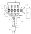
図1は、本発明の実施形態に係る多気筒エンジンの排気装置100の概略構成図、図2は、図1の排気系の拡大図、図3は、前記エンジンの排気マニホールド5及び触媒装置6の概略側面図である。この排気装置100は、シリンダヘッド9及びシリンダブロック(図示せず)を有するエンジン本体1と、エンジン制御用のECU2と、エンジン本体1に接続される複数の独立吸気通路3…3等を含む吸気系と、エンジン本体1に接続される排気マニホールド5と、排気マニホールド5に接続される触媒装置6とを備えている。
(1) Overall Configuration FIG. 1 is a schematic configuration diagram of an
前記シリンダヘッド9及びシリンダブロックの内部にはピストンがそれぞれ嵌挿された複数(図例では4つ)の気筒12が形成されている。本実施形態では、エンジン本体1は、直列4気筒のエンジンであって、シリンダヘッド9及びシリンダブロックの内部には、4つの気筒12が直列に並んだ状態で形成されている。具体的には、図1及び図2の右から順に、第1気筒12a、第2気筒12b、第3気筒12c、第4気筒12dが形成されている。シリンダヘッド9には、ピストンの上方に区画された燃焼室内に臨むようにそれぞれ点火プラグ15が設置されている。
Inside the
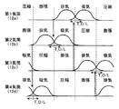
エンジン本体1は4サイクルエンジンであって、図6に示すように、各気筒12a〜12dにおいて、180°CAずつずれたタイミングで点火プラグ15による点火が行われて、吸気行程、圧縮行程、膨張行程、排気行程の各行程がそれぞれ180°CAずつずれたタイミングで行われる。本実施形態では、第1気筒12a→第3気筒12c→第4気筒12d→第2気筒12bの順に点火が行われ、この順に各行程が実施される。
The
シリンダヘッド9には、それぞれ燃焼室に向かって開口する2つの吸気ポート17及び2つの排気ポート18が設けられている。吸気ポート17は、各気筒12内に吸気を導入するためのものである。排気ポート18は、各気筒12内から排気を排出するためのものである。各吸気ポート17には、これら吸気ポート17を開閉して吸気ポート17と気筒12内部とを連通又は遮断するための吸気弁19が設けられている。各排気ポート18には、これら排気ポート18を開閉して排気ポート18と気筒12内部とを連通又は遮断するための排気弁20が設けられている。吸気弁19は、吸気弁駆動機構30で駆動されることにより、所定のタイミングで吸気ポート17を開閉する。排気弁20は、排気弁駆動機構40で駆動されることにより、所定のタイミングで排気ポート18を開閉する。
The
吸気弁駆動機構30は、吸気弁19に連結された吸気カムシャフト31と吸気VVT32とを有している。排気弁駆動機構40は、排気弁20に連結された排気カムシャフト41と排気VVT42とを有している。吸気カムシャフト31及び排気カムシャフト41は、周知のチェーン及びスプロケット機構等の動力伝達機構を介してクランクシャフトに連結されており、クランクシャフトの回転に伴い回転して、吸気弁19及び排気弁20を開閉駆動する。
The intake
吸気VVT32及び排気VVT42は、吸気弁19及び排気弁20のバルブタイミングを変更するためのものである。例えば、吸気VVT32は、吸気カムシャフト31と同軸に配置されてクランクシャフトにより直接駆動される所定の被駆動軸を有し、この被駆動軸と吸気カムシャフト31との間の位相差を変更する。これにより、クランクシャフトと吸気カムシャフト31との間の位相差が変更され、吸気弁19のバルブタイミングが変更される。排気VVT42もこれに準じて同様である。
The
吸気VVT32及び排気VVT42の具体的構成としては、例えば、前記被駆動軸と吸気カムシャフト31又は排気カムシャフト41との間に周方向に並ぶ複数の液室を有し、これらの液室間に圧力差を設けることで前記位相差を変更する液圧式機構や、前記被駆動軸と吸気カムシャフト31又は排気カムシャフト41との間に電磁石を配設し、この電磁石に電力を付与することで前記位相差を変更する電磁式機構等が挙げられる。吸気VVT32及び排気VVT42は、ECU2で算出された吸気弁19及び排気弁20の目標バルブタイミングに基づいて前記位相差を変更する。
As specific configurations of the
本実施形態では、吸気VVT32及び排気VVT42は、吸気弁19及び排気弁20の開弁期間及びリフト量、つまりバルブプロファイルをそれぞれ一定に保ったまま、吸気弁19及び排気弁20の開弁時期(図7に示す開弁開始時期)及び閉弁時期をそれぞれ変更する。
In the present embodiment, the
本実施形態では、吸気弁19及び排気弁20の開弁時期及び閉弁時期とは、図7に示すように、各バルブのリフトカーブにおいてバルブのリフトが急峻に立ち上がる時期又は立ち下がる時期であり、例えば0.4mmリフトの時期をいう。
In this embodiment, the valve opening timing and the valve closing timing of the
(2)排気系の構成
図1〜図3に示すように、排気マニホールド5は、上流側から順に、1つの気筒12又は排気順序が連続しない2つの気筒12の排気ポート18にそれぞれ接続された3つの独立排気通路52と、各独立排気通路52の下流端部に接続されて各独立排気通路52を通過した排気が流入し、集合する混合管50とを有する。
(2) Configuration of Exhaust System As shown in FIGS. 1 to 3, the
前記混合管50は、その軸芯L1(図3参照)上に、上流側から順に、流路面積が上流側から下流側に向けて徐々に縮小するテーパ部56と、前記テーパ部56の下流端の流路面積(混合管50の最小流路面積)を維持して下流側に延びるストレート部57と、流路面積が上流側から下流側に向けて徐々に拡大するディフューザ部58とを備えている。
The mixing
本実施形態では、前記テーパ部56は、下流側ほど縮径する逆円錐台形状とされ、前記ストレート部57は、円筒形状とされ、前記ディフューザ部58は、下流側ほど拡径する円錐台形状とされている。すなわち、前記テーパ部56、ストレート部57及びディフューザ部58の各内面は、混合管50の軸芯L1に沿う断面視において、例えば曲線や複数の直線の組合せではなく、単一の直線で構成されている。その結果、テーパ部56の内面は、混合管50の軸芯L1に対し一定の角度θ1(図8参照)で上流に向けて開く傾斜面とされ、ディフューザ部58の内面は、混合管50の軸芯L1に対し一定の角度θ2(図8参照)で下流に向けて開く傾斜面とされている。
In the present embodiment, the tapered
各独立排気通路52は、各気筒12の排気ポート18に接続されている。具体的には、4つの気筒12のうち、排気行程が隣り合わず排気順序が連続しない第2気筒12bの排気ポート18と第3気筒12cの排気ポート18とは、共通の1つの独立排気通路52bに接続されている。より詳細には、独立排気通路52bは、その上流側において2つの通路に分離しており、その一方に第2気筒12bの排気ポート18が接続され、他方に第3気筒12cの排気ポート18が接続されている。これに対し、第1気筒12aの排気ポート18及び第4気筒12dの排気ポート18は、それぞれ単独の独立排気通路52a,52dに接続されている。
Each
3つの独立排気通路52a,52b,52dは互いに独立しており、第1気筒12aから排出された排気と、第2気筒12b又は第3気筒12cから排出された排気と、第4気筒12dから排出された排気とは、互いに独立して各独立排気通路52a,52b,52dを下流側に通過し、各独立排気通路52a,52b,52dの下流端部から混合管50のテーパ部56に噴出する。
The three
本実施形態では、各気筒12から排出された排気の流速ができるだけ低下せずに混合管50に噴出するように、各独立排気通路52の長さが制限されている。すなわち、できるだけ短くされている。
In the present embodiment, the length of each
各独立排気通路52の下流端部は、下流側ほど流路面積が小さくなる先細り部とされている。これにより、各独立排気通路52の下流端部から混合管50に噴出するときの排気の流速は、各独立排気通路52を先細り部まで通過してきた排気の流速よりも大きくなり、排気は、各独立排気通路52の下流端部から混合管50のテーパ部56に高速で噴出する。
The downstream end portion of each
本実施形態では、図4及び図5に示すように、各独立排気通路52a,52b,52dの下流端部は、断面形状が扇形とされ、この扇形が集合して全体として略円形断面を形成するように束ねられて、前記混合管50のテーパ部56の上流端に接続されている(図1〜図3参照)。
In the present embodiment, as shown in FIGS. 4 and 5, the downstream end portions of the
このような構成により、各独立排気通路52を通過した排気が高速で混合管50に噴出したときには、混合管50内に負圧が発生し、この負圧によって、排気を噴出した独立排気通路52に隣接する他の独立排気通路52ないしこれと連通する他の気筒12の排気ポート18内の排気が下流側に吸い出されるエゼクタ効果が奏される。
With such a configuration, when the exhaust gas that has passed through each
そして、このエゼクタ効果を高めるように、混合管50のテーパ部56は、下流側ほど流路面積が縮小する形状とされている。これにより、各独立排気通路52の下流端部からテーパ部56に噴出した排気は、高い流速を維持したままテーパ部56及びストレート部57を下流側に流れ、混合管50内(特にテーパ部56からストレート部57)に発生する負圧が大きくなる。
And the
本実施形態では、混合管50のテーパ部56及びストレート部57を流れる排気の流速をより高めるように、テーパ部56の下流端の流路面積(すなわち混合管50の最小流路面積であってストレート部57の流路面積に同じ)は、3つの独立排気通路52の下流端部の流路面積の合計値よりも小さい値に設定されている。例えば、各独立排気通路52の下流端部の流路面積と同じ面積を有する真円の直径をaとし、テーパ部56の下流端の流路面積と同じ面積を有する真円の直径をDとしたときに、a/Dが0.58以上に設定されている。ただし、a/Dが大き過ぎると、各独立排気通路52の下流端部から噴出した排気の流れが滞って、混合管50内に発生する負圧が小さくなり、エゼクタ効果が不足する可能性がある。そこで、a/Dの好ましい範囲は、例えば0.58〜0.85である。
In the present embodiment, the flow area of the downstream end of the tapered portion 56 (that is, the minimum flow area of the mixing
独立排気通路52の下流端部からテーパ部56に噴出した排気が高速でテーパ部56及びストレート部57を通過することにより、テーパ部56からストレート部57にかけて発生する負圧が大きくなる(つまり排気の圧力が低下する)と共に、排気の温度が低下する。そのため、テーパ部56及びストレート部57において、排気の外部への放熱量は小さく抑えられる。このことは触媒の活性化に有利に働く。そして、ストレート部57を通過した排気は、下流側ほど流路面積が大きくなる形状のディフューザ部58に流入することにより流速が低下する一方で、排気の圧力及び温度が回復し、高圧高温状態に戻った状態で触媒装置6に流入する。
As the exhaust gas ejected from the downstream end portion of the
触媒装置6は、エンジン本体1から排出された排気を浄化するための装置である。この触媒装置6は、排気中の有害成分を浄化する機能を有する触媒本体64と、この触媒本体64を収容するケーシング62とを備えている。ケーシング62は、排気の流通方向と平行に延びる略円筒状を有している。触媒本体64は、例えば三元触媒を含有し、理論空燃比の雰囲気下で、HC(炭化水素)、CO(一酸化炭素)、NOx(窒素酸化物)を同時に酸化又は還元して除去し得る三元触媒機能を有する。
The
触媒本体64は、ケーシング62の排気流通方向の中央の拡径部分に収容されている。ケーシング62の上流側にはコーン部(円錐部)61が形成され、このコーン部61から上流側に円筒状の通路部60が延設されている。前記混合管50のディフューザ部58の下流端は前記通路部60の上流端に接続されている。ディフューザ部58から排出された排気は前記通路部60及びコーン部61を通過した後、触媒本体64に流入する。このとき、前述したように、混合管50のディフューザ部58を通過した排気は、高圧高温状態に戻っている。そのため、相対的に高い温度の排気が高圧で触媒本体64に流入し、これにより、触媒本体64は早期に活性化され、また、触媒本体64の活性化状態が良好に維持される。
The catalyst
本実施形態では、各気筒12から排出された排気の温度ができるだけ低下せずに触媒本体64に流入するように、触媒装置6は排気系の相対的に上流側に設置されている。そのため、例えば混合管50の上流端部から触媒装置6のケーシング62のコーン部61までの長さ(図2に示す符号A)が1m以下に制限されている。
In the present embodiment, the
(3)本実施形態の特徴
[3−1]低速域でのエゼクタ効果
ECU2は、少なくとも低速域(例えば2700rpm〜2800rpm以下の回転域)においては、各気筒12の吸排気開弁期間が所定のオーバーラップ期間を有し、排気順序が連続する気筒12,12間において一方の気筒12のオーバーラップ期間が他方の気筒12の排気開弁時期に重複するように、吸気弁駆動機構30の吸気VVT32及び排気弁駆動機構40の排気VVT42を制御する。
(3) Features of the present embodiment [3-1] Ejector effect in the low speed range The
より具体的には、低速域においては、図6に示すように、各気筒12の排気弁20の開弁期間と吸気弁19の開弁期間とが吸気上死点(TDC)を挟んでオーバーラップし、且つ、排気順序が連続する気筒12,12間において、一方の気筒(先行する気筒)12のオーバーラップ期間T_O/L中に、他方の気筒(後続の気筒)12の排気弁20が開弁を開始するように、吸気VVT32及び排気VVT42が制御される。例えば、第1気筒12aの排気弁20と吸気弁19とがオーバーラップしている期間中に第3気筒12cの排気弁20が開弁し、第3気筒12cの排気弁20と吸気弁19とがオーバーラップしている期間中に第4気筒12dの排気弁20が開弁し、第4気筒12dの排気弁20と吸気弁19とがオーバーラップしている期間中に第2気筒12bの排気弁20が開弁し、第2気筒12bの排気弁20と吸気弁19とがオーバーラップしている期間中に第1気筒12aの排気弁20が開弁するように、吸気VVT32及び排気VVT42がECU2によって制御される。
More specifically, in the low speed range, as shown in FIG. 6, the valve opening period of the
これにより、排気行程気筒12の排気弁20が開弁してブローダウンガスがこの排気行程気筒12から独立排気通路52を通って混合管50のテーパ部56に高速で噴出されるのに伴い、エゼクタ効果によりオーバーラップ期間T_O/L中の吸気行程気筒12の排気ポート18内に負圧が生成される。そのため、前記エゼクタ効果がオーバーラップ期間T_O/L中の吸気行程気筒12の排気ポート18だけでなく、吸気行程気筒12から吸気行程気筒12の吸気ポート17にまで及び、このオーバーラップ期間T_O/L中の吸気行程気筒12の掃気が促進される。その結果、少なくとも低速域においては、本実施形態に係る多気筒エンジンは、エゼクタ効果によって、体積効率(ηV)の向上ひいてはトルクの向上が図られる。
As a result, the
[3−2]混合管の構造
次に、図8を参照して、混合管50の構造をさらに詳しく説明する。なお、図8に示した独立排気通路52、テーパ部56、ストレート部57、ディフューザ部58及び触媒装置6の通路部60は、それぞれ各部位の内面が描かれている。
[3-2] Structure of Mixing Tube Next, the structure of the mixing
前述したように、混合管50は、その軸芯L1上に、上流側から順に、流路面積が上流側から下流側に向けて徐々に縮小するテーパ部56と、流路面積が最小のストレート部57と、流路面積が上流側から下流側に向けて徐々に拡大するディフューザ部58とを備えている。テーパ部56の上流端に独立排気通路52(図8には1つのみ図示)の下流端部が接続され、この独立排気通路52の下流端部から噴出した排気が高速でテーパ部56及びストレート部57を通過することによって混合管50内に負圧が発生し、この負圧により他の独立排気通路52の排気が吸い出されるエゼクタ効果が奏される。また、ストレート部57を通過した排気がディフューザ部58に流入することによって排気の圧力及び温度が回復し、排気は高圧高温状態に戻った状態で触媒装置6に流入する。
As described above, the mixing
このような混合管50の機能を良好に発揮させるためには、テーパ部56は、独立排気通路52から噴出した排気が高い流速を維持したままストレート部57に流れ込むような形状とするのが望ましく、ディフューザ部58は、圧力損失なく排気の圧力が高圧に戻るような形状とするのが望ましい。
In order to make the function of the mixing
ただし、本実施形態では、前述したように、エゼクタ効果や触媒活性化に有利な観点から、排気系の長さが制限(できるだけ短く)されており、その一環として、図8に符号Bで示す混合管50の長さもまた制限されている。
However, in the present embodiment, as described above, the length of the exhaust system is limited (as short as possible) from the viewpoint of being advantageous for the ejector effect and catalyst activation, and as shown in FIG. The length of the mixing
以上のような事情を考慮して、本実施形態では、混合管50は、テーパ部56の流路面積の縮小率の平均値を△S1とし、ディフューザ部58の流路面積の拡大率の平均値を△S2としたときに、△S1>△S2となるように構成されている。なお、前述したように、本実施形態では、テーパ部56の内面は、混合管50の軸芯L1に対し一定の角度θ1で上流に向けて開く傾斜面とされ、ディフューザ部58の内面は、混合管50の軸芯L1に対し一定の角度θ2で下流に向けて開く傾斜面とされている。つまり、テーパ部56の流路面積の縮小率は、△S1で一定(一律に△S1)であり、ディフューザ部58の流路面積の拡大率は、△S2で一定(一律に△S2)である。したがって、前記△S1>△S2の関係を角度でθ1>θ2と表すことが可能となる。以下、この開き角度(又は傾斜角度)θ1,θ2を用いて説明する。
In consideration of the above circumstances, in the present embodiment, the mixing
まず、テーパ部56では、独立排気通路52から噴出した排気の噴流がテーパ部56の内面に衝突してその流速が低下することがないように、テーパ部56の内面の開き角度θ1が決められる。テーパ部56の内面の開き角度θ1は、テーパ部56の上流端の径及び下流端の径により影響を受ける。また、テーパ部56の上流端と下流端との距離(テーパ部56の長さ)によっても影響を受ける。例えば、テーパ部56の上流端の径が大きいほど、下流端の径が小さいほど、上流端と下流端との距離が短いほど、テーパ部56の内面の開き角度θ1は大きくなる。
First, in the
ここで、前述したように、本実施形態では、独立排気通路52の下流端部の流路面積と同じ面積を有する真円の直径をaとし、テーパ部56の下流端の流路面積と同じ面積を有する真円の直径をDとしたときに、a/Dが0.58以上に設定されている。定義より、aはテーパ部56の上流端の径に相関し、Dはテーパ部56の下流端の径に相関する。すなわち、テーパ部56の上流端の径と下流端の径との関係は、a/Dによって略定まっている。一方、混合管50の長さBが制限されているから、テーパ部56の長さ(テーパ部56の上流端と下流端との距離)が相対的に短くされる。その結果、テーパ部56の内面の開き角度θ1は相対的に大きくなる傾向となる。そして、このテーパ部56の内面の開き角度θ1に合わせて、独立排気通路52の下流端部の先細り部の傾斜角度(独立排気通路52からの排気の噴出角度)が決められる。
Here, as described above, in this embodiment, the diameter of a perfect circle having the same area as the flow path area at the downstream end of the
一方、ディフューザ部58では、排気の流れがディフューザ部58の内面から剥離することがないように、ディフューザ部58の内面の開き角度θ2が決められる。排気の流れがディフューザ部58の内面から剥離すると、乱流が生じ、排気の運動エネルギーが熱エネルギーに変わって、圧力に変換されず、圧力損失が生じるからである。圧力損失が生じると、最終的に大気圧まで戻るべき元の圧力が高くなってしまう。つまり、混合管50内の負圧が小さくなってしまう。混合管50内の負圧が小さくなると、気筒12から排気が排出される際の排気抵抗が増大し、排気の流速が低下し、混合管50内の負圧がより小さくなって、エゼクタ効果が弱まってしまう。また、排気抵抗が増大すると、気筒12内でピストンの上昇が抵抗を受け、エンジントルクにも影響する。したがって、排気抵抗を小さくして、気筒12から排気(ブローダウンガス)が高速で排出されるように、混合管50内の負圧をできるだけ大きくすることが重要である。そして、そのために、ディフューザ部58は、混合管50内の負圧が圧力損失なく高圧に戻るように、すなわちディフューザ効率が良好となるように構成することが肝要である。
On the other hand, in the
以上のような観点から、ディフューザ部58の内面の開き角度θ2は、なるべく小さいほうが好ましい。ディフューザ部58の内面の開き角度θ2が小さくなるほど、排気の流れがディフューザ部58の内面から剥離する傾向が小さくなるからである。しかし、ディフューザ部58の内面の開き角度θ2を小さくすると、ディフューザ部58の上流端と下流端との距離(ディフューザ部58の長さ)が長くなり、混合管50の長さBを制限するという要請に反することになる。一方、図8に鎖線で示すように、混合管50の下流端部(ディフューザ部58の下流端)を触媒装置6の通路部60に段差なく連続して接続すると、ディフューザ部58の内面の開き角度θ2が大きくなる。
From the above viewpoint, the opening angle θ2 of the inner surface of the
後述する実機試験で説明するように、たとえ混合管50の下流端部と触媒装置6の通路部60との接続部に段差が生じても、ディフューザ部58の内面の開き角度θ2をできるだけ小さくするほうが、混合管50の下流端部を触媒装置6の通路部60に段差なく連続して接続するよりも、良い結果が得られる(排気抵抗が減少し、混合管内の負圧が大きくなり、エゼクタ効果が高まる)ことが見出された。
As will be described in an actual machine test to be described later, even if a step is generated at the connecting portion between the downstream end portion of the mixing
以上を総合して、本実施形態では、テーパ部56の内面の開き角度をθ1とし、ディフューザ部58の内面の開き角度をθ2としたときに、θ1は相対的に大きくなる傾向となり、θ2は小さいほうが良い結果が得られるので、θ1>θ2となるように混合管50を構成しているのである。
In summary, in the present embodiment, when the opening angle of the inner surface of the tapered
ここで、テーパ部56の内面の開き角度θ1の好ましい範囲は、5°以上、13°以下であり、ディフューザ部58の内面の開き角度θ2の好ましい範囲は、7°以下(0°を除く)である。
Here, the preferable range of the opening angle θ1 of the inner surface of the tapered
[3−3]実機試験
<1> 図8に示す仕様(θ1>θ2)の混合管50についてエゼクタ効果の実機試験を行った。テーパ部56の内面の開き角度θ1を9°とし、ディフューザ部58の内面の開き角度θ2を5°とした。結果を図9に示す。
[3-3] Actual Machine Test <1> An actual machine test of the ejector effect was performed on the mixing
図9は、ある1つの気筒12から排出された排気が独立排気通路52の下流端部から混合管50のテーパ部56に噴出したときの混合管50内の圧力分布図である。図中、ハッチングした領域は、混合管50内で負圧が最大であった領域である。後述する比較例(図15:θ1<θ2)と比べて、負圧最大領域がテーパ部56からストレート部57に亘って広い範囲で生じていることが分かる。
FIG. 9 is a pressure distribution diagram in the mixing
混合管50の上流端部(テーパ部56の上流端)における圧力(負圧)をP1とし、混合管50の下流端部(ディフューザ部58の下流端)における圧力(負圧)をP2としたときに、その圧力差、すなわち負圧差△P(図8参照)は、49.9kPaであった。これは、比較例(図15)と比べて、大きい値である。 The pressure (negative pressure) at the upstream end of the mixing tube 50 (upstream end of the tapered portion 56) is P1, and the pressure (negative pressure) at the downstream end of the mixing tube 50 (downstream end of the diffuser portion 58) is P2. Sometimes, the pressure difference, that is, the negative pressure difference ΔP (see FIG. 8) was 49.9 kPa. This is a large value compared to the comparative example (FIG. 15).
この結果から、図8に示す仕様(θ1>θ2)の混合管50は、混合管50の下流端部と触媒装置6の通路部60との接続部に段差が生じているけれども、ディフューザ部58においてディフューザ効率が良好となる開き角度θ2が維持されているので、剥離が起こらず、圧力損失が生じず、排気抵抗が減少し、混合管50内に発生する負圧が大きくなり、エゼクタ効果が高められることが分かる。
From this result, in the mixing
<2> テーパ部の内面の開き角度θ1を9°に固定して、ディフューザ部の内面の開き角度θ2を2°から17.5°まで変化させたときに、混合管内に発生する負圧の最大値を調べた。また、ディフューザ部の内面の開き角度θ2を5°に固定して、テーパ部の内面の開き角度θ1を6°から17°まで変化させたときに、混合管内に発生する負圧の最大値を調べた。結果を図10に示す。 <2> When the opening angle θ1 of the inner surface of the taper portion is fixed at 9 ° and the opening angle θ2 of the inner surface of the diffuser portion is changed from 2 ° to 17.5 °, the negative pressure generated in the mixing tube The maximum value was examined. Further, when the opening angle θ2 of the inner surface of the diffuser portion is fixed to 5 ° and the opening angle θ1 of the inner surface of the taper portion is changed from 6 ° to 17 °, the maximum value of the negative pressure generated in the mixing tube is set. Examined. The results are shown in FIG.
テーパ部の内面の開き角度θ1については、8°のときに、ディフューザ部の内面の開き角度θ2については、2°〜3°のときに、それぞれ、混合管内に発生する負圧の最大値がピークとなる。この結果からも、θ1>θ2の関係が、混合管50内に発生する負圧を大きくし、エゼクタ効果を高める観点から好ましい仕様であることが分かる。
When the opening angle θ1 of the inner surface of the taper portion is 8 °, and when the opening angle θ2 of the inner surface of the diffuser portion is 2 ° to 3 °, the maximum value of the negative pressure generated in the mixing tube is respectively It becomes a peak. Also from this result, it can be seen that the relationship of θ1> θ2 is a preferable specification from the viewpoint of increasing the negative pressure generated in the mixing
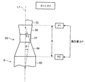
<3> 図8に示す仕様(θ1>θ2)に別の仕様を追加した混合管50についてエゼクタ効果の実機試験を行った。すなわち、図11に示すように、この混合管50は、ディフューザ部58の下流端が、触媒装置6の通路部60を介さずに、触媒装置6のケーシング62のコーン部61に直接接続されている。これによれば、混合管50の上流端部から触媒装置6のケーシング62のコーン部61までの長さ(図2に示す符号A)が混合管50の長さBに一致するまで短くなり、より一層触媒の活性化に有利となる。
<3> An actual test of the ejector effect was performed on the mixing
図12に示すように、この別の仕様を追加した混合管50は、ディフューザ部58が、上流側の第1ディフューザ部58aと、下流側の第2ディフューザ部58bとを含んでいる。そして、第2ディフューザ部58bの下流端が触媒装置6のケーシング62のコーン部61に段差なく連続して接続されている。そして、混合管50は、第1ディフューザ部58aの流路面積の拡大率の平均値を△S2とし、第2ディフューザ部58bの流路面積の拡大率の平均値を△S3としたときに、△S3>△S2となるように構成されている。すなわち、開き角度(又は傾斜角度)θ2,θ3で表すと、θ3>θ2となるように構成されている。
As shown in FIG. 12, in the mixing
また、テーパ部56については、図8に示す仕様(θ1>θ2)と同じである。そして、△S3と△S1との関係は、第1ディフューザ部58aの下流端の径、コーン部61の上流端の径、及び第1ディフューザ部58aの下流端とコーン部61の上流端との距離(第2ディフューザ部58bの長さ)に依存して変化し得るが、本実施形態では、△S3≧△S1となるように構成されている。すなわち、開き角度(又は傾斜角度)θ1,θ3で表すと、θ3≧θ1となるように構成されている。
Further, the
図12に示す仕様(θ3≧θ1>θ2)の混合管50についてエゼクタ効果の実機試験を行った。テーパ部56の内面の開き角度θ1を9°とし、第1ディフューザ部58aの内面の開き角度θ2を5°とし、第2ディフューザ部58bの内面の開き角度θ3を15.8°とした。結果を図13に示す。
An actual machine test of the ejector effect was performed on the mixing
図13は、図9と同様、ある1つの気筒12から排出された排気が独立排気通路52の下流端部から混合管50のテーパ部56に噴出したときの混合管50内の圧力分布図である。図中、ハッチングした領域は、混合管50内で負圧が最大であった領域である。比較例(図15)と比べて、負圧最大領域がテーパ部56からストレート部57に亘って広い範囲で生じていることが分かる。
FIG. 13 is a pressure distribution diagram in the mixing
混合管50の上流端部(テーパ部56の上流端)における圧力(負圧)をP1とし、混合管50の下流端部(ディフューザ部58の下流端)における圧力(負圧)をP2としたときに、その圧力差、すなわち負圧差△P(図12参照)は、47.0kPaであった。これは、比較例(図15)と比べて、大きい値である。 The pressure (negative pressure) at the upstream end of the mixing tube 50 (upstream end of the tapered portion 56) is P1, and the pressure (negative pressure) at the downstream end of the mixing tube 50 (downstream end of the diffuser portion 58) is P2. Sometimes, the pressure difference, that is, the negative pressure difference ΔP (see FIG. 12) was 47.0 kPa. This is a large value compared to the comparative example (FIG. 15).
この結果から、図12に示す仕様(θ3≧θ1>θ2)の混合管50は、混合管50の下流端部が触媒装置6のコーン部61に段差なく連続して接続されているため、第2ディフューザ部58bの開き角度θ3が大きくなっているけれども、第1ディフューザ部58aにおいてディフューザ効率が良好となる開き角度θ2が維持されているので、剥離が起こらず、圧力損失が生じず、排気抵抗が減少し、混合管50内に発生する負圧が大きくなり、エゼクタ効果が高められることが分かる。
From this result, the mixing
<4> 図8に示す仕様(θ1>θ2)とは別の仕様の混合管50についてエゼクタ効果の実機試験を行った(比較例)。すなわち、図14に示すように、この混合管50は、ディフューザ部58の下流端が、触媒装置6の通路部60に段差なく連続して接続されている(図8の鎖線参照)。その結果、ディフューザ部58の内面の開き角度θ2が相対的に大きくなり、θ1<θ2となっている。
<4> An actual machine test of the ejector effect was performed on the mixing
図14に示す仕様(θ1<θ2)の混合管50についてエゼクタ効果の実機試験を行った。テーパ部56の内面の開き角度θ1を9°とし、ディフューザ部58の内面の開き角度θ2を10.5°とした。結果を図15に示す。
An actual machine test of the ejector effect was performed on the mixing
図15は、図9と同様、ある1つの気筒12から排出された排気が独立排気通路52の下流端部から混合管50のテーパ部56に噴出したときの混合管50内の圧力分布図である。図中、ハッチングした領域は、混合管50内で負圧が最大であった領域である。実施形態(図9、図13)と比べて、負圧最大領域が小さくなっていることが分かる。
FIG. 15 is a pressure distribution diagram in the mixing
混合管50の上流端部(テーパ部56の上流端)における圧力(負圧)をP1とし、混合管50の下流端部(ディフューザ部58の下流端)における圧力(負圧)をP2としたときに、その圧力差、すなわち負圧差△P(図14参照)は、43.4kPaであった。これは、実施形態(図9、図13)と比べて、小さい値である。 The pressure (negative pressure) at the upstream end of the mixing tube 50 (upstream end of the tapered portion 56) is P1, and the pressure (negative pressure) at the downstream end of the mixing tube 50 (downstream end of the diffuser portion 58) is P2. Sometimes, the pressure difference, that is, the negative pressure difference ΔP (see FIG. 14) was 43.4 kPa. This is a small value compared to the embodiment (FIGS. 9 and 13).
この結果から、図14に示す仕様(θ1<θ2)の混合管50は、混合管50の下流端部が触媒装置6のコーン部61に段差なく連続して接続されているため、ディフューザ部58の開き角度θ2が大きくなり、剥離が起こり、圧力損失が生じ、排気抵抗が増大し、混合管50内に発生する負圧が小さくなり、エゼクタ効果が弱められることが分かる。
From this result, the mixing
[3−4]作用
本実施形態においては、混合管50の長さBを制限するという要請の下、混合管50のテーパ部56の内面の開き角度θ1をディフューザ部58の内面の開き角度θ2よりも大きくした(θ1>θ2)から、混合管50のテーパ部56の内面の開き角度θ1をディフューザ部58の内面の開き角度θ2と同じ又はそれよりも小さくした(θ1≦θ2)場合に比べて、各気筒12から排出された排気が混合管50に噴出したときに該混合管50内に発生する負圧が大きくなる。そのため、低速域でのエゼクタ効果が高められ、広い回転域に亘ってトルクが向上し、トルクがワイドレンジ化した多気筒エンジンが実現する。
[3-4] Action In the present embodiment, the opening angle θ1 of the inner surface of the tapered
また、混合管50のディフューザ部58を上流側の第1ディフューザ部58aと下流側の第2ディフューザ部58bとで構成し、第2ディフューザ部58bの内面の開き角度θ3を第1ディフューザ部58aの内面の開き角度θ2よりも大きくした(θ3>θ2)場合には、混合管50のテーパ部56と第1ディフューザ部58aとの間で、θ1>θ2の関係を維持しつつ、混合管50の下流端部(第2ディフューザ部58bの下流端)を触媒装置60のコーン部61に段差なく連続して接続することができる。しかも、その場合、ディフューザ部58の内面の開き角度をθ2で一定とした場合に比べて、混合管50の軸方向の長さBを短くでき、触媒の活性化に有利となる。
Further, the
また、第2ディフューザ部58bの内面の開き角度θ3をテーパ部56の内面の開き角度θ1と同じ又はそれよりも大きくした(θ3≧θ1)場合には、θ3<θ1となるように混合管50を構成した場合に比べて、混合管50の軸方向の長さBをさらに短くでき、触媒の活性化により一層有利となる。
Further, when the opening angle θ3 of the inner surface of the
また、テーパ部56の内面の開き角度θ1、第1ディフューザ部58aの内面の開き角度θ2、及び第2ディフューザ部58bの内面の開き角度θ3がそれぞれ一定なので、混合管50の成形が容易となる。
Further, since the opening angle θ1 of the inner surface of the tapered
(4)本実施形態の変形例
前記実施形態では、混合管50のテーパ部56、ストレート部57及びディフューザ部58の各内面は、混合管50の軸芯L1に沿う断面視において、単一の直線で構成されている場合であったが、図16に例示するように、例えば曲線で構成されていてもよい。図16において、テーパ部56の流路面積の縮小率の平均値△S1、第1ディフューザ部58aの流路面積の拡大率の平均値△S2、第2ディフューザ部58bの流路面積の拡大率の平均値△S3は、それぞれ、各曲線に対する接線の傾きの平均値で表される。なお、図16では、ストレート部57は、軸芯L1方向の長さがほとんどないものとされている。
(4) Modification of the present embodiment In the above-described embodiment, the inner surfaces of the tapered
また、吸気弁19と排気弁20とのオーバーラップ期間T_O/Lを設け、一方の気筒12のオーバーラップ期間T_O/Lと他方の気筒12の排気開弁時期とを重複させる制御を行うのは、低速域でも高負荷域のみとしてもよい。
In addition, an overlap period T_O / L between the
12 気筒
17 吸気ポート
18 排気ポート
19 吸気弁
20 排気弁
30 吸気弁駆動機構
32 吸気VVT
40 排気弁駆動機構
42 排気VVT
50 混合管
52 独立排気通路
56 テーパ部(上流部位)
57 ストレート部(中間部位)
58 ディフューザ部(下流部位)
58a 第1ディフューザ部(第1下流部位)
58b 第2ディフューザ部(第2下流部位)
60 触媒装置上流側通路部
61 触媒装置ケーシング上流側コーン部
62 触媒装置ケーシング
100 排気装置
12
40 Exhaust
50
57 Straight part (intermediate part)
58 Diffuser section (downstream part)
58a First diffuser portion (first downstream portion)
58b 2nd diffuser part (2nd downstream part)
60 Catalytic device upstream
Claims (4)
1つの気筒又は排気順序が連続しない複数の気筒の排気ポートにそれぞれ接続された複数の独立排気通路と、前記独立排気通路の各下流端部が束ねられて接続され、各独立排気通路の下流端部から噴出した排気が集合する混合管とが設けられ、
少なくともエンジン低速域においては、各気筒の吸排気開弁期間が所定のオーバーラップ期間を有し、排気順序が連続する気筒間において一方の気筒のオーバーラップ期間が他方の気筒の排気開弁時期に重複するように設定され、
前記混合管は、流路面積が最小の中間部位と、当該中間部位から上流側に延びて前記独立排気通路の各下流端部に接続されるとともに流路面積が上流側から下流側に向けて徐々に縮小する上流部位と、前記中間部位から下流側に延びて流路面積が上流側から下流側に向けて徐々に拡大する下流部位とを有し、
前記上流部位の下流端の流路面積および前記下流部位の上流端の流路面積は、それぞれ前記中間部位の流路面積と一致しており、
前記混合管の下流部位の下流端部には、内側に触媒本体を収容するケーシングが、前記混合管の下流部位の下流端部の中心と前記ケーシングの上流端部の中心とが略一致するように接続され、
前記中間部位から前記ケーシングまでの部分の流路面積は、下流側ほど大きくなるように設定されており、
前記上流部位の流路面積の縮小率の平均値を△S1とし、前記下流部位の流路面積の拡大率の平均値を△S2としたときに、△S1>△S2となるように設定されていることを特徴とする多気筒エンジンの排気装置。 An exhaust device for a multi-cylinder engine having a plurality of cylinders provided with an intake valve capable of opening and closing an intake port and an exhaust valve capable of opening and closing an exhaust port,
A plurality of independent exhaust passages connected to exhaust ports of one cylinder or a plurality of cylinders whose exhaust order is not continuous, and respective downstream end portions of the independent exhaust passages are connected in a bundle, and the downstream end of each independent exhaust passage And a mixing tube for collecting exhaust gas ejected from the section,
At least in the engine low speed range, the intake / exhaust valve opening period of each cylinder has a predetermined overlap period, and the overlap period of one cylinder is the exhaust valve opening time of the other cylinder between cylinders in which the exhaust order is continuous. Set to overlap,
The mixing pipe is connected to the intermediate part having the smallest flow area and the upstream side from the intermediate part and connected to each downstream end of the independent exhaust passage, and the flow area is from the upstream side to the downstream side. An upstream part that gradually decreases, and a downstream part that extends from the intermediate part to the downstream side and the flow channel area gradually increases from the upstream side to the downstream side,
The flow area of the downstream end of the upstream part and the flow area of the upstream end of the downstream part are respectively coincident with the flow area of the intermediate part,
At the downstream end of the downstream portion of the mixing tube , a casing that accommodates the catalyst body inside is arranged such that the center of the downstream end of the downstream portion of the mixing tube substantially coincides with the center of the upstream end of the casing. Connected to
The flow area of the part from the intermediate part to the casing is set to increase toward the downstream side,
ΔS1> ΔS2 is set so that ΔS1 is an average value of the reduction ratio of the channel area in the upstream region and ΔS2 is an average value of the expansion ratio of the channel area in the downstream region. An exhaust system for a multi-cylinder engine.
前記上流部位の内面は、混合管の軸芯に対し一定の角度θ1で上流に向けて開く傾斜面とされ、前記下流部位の内面は、混合管の軸芯に対し一定の角度θ2で下流に向けて開く傾斜面とされ、前記上流部位の内面の開き角度をθ1とし、前記下流部位の内面の開き角度をθ2としたときに、θ1>θ2となるように設定されていることを特徴とする多気筒エンジンの排気装置。 The exhaust system for a multi-cylinder engine according to claim 1,
The inner surface of the upstream portion is an inclined surface that opens toward the upstream at a constant angle θ1 with respect to the axial center of the mixing tube, and the inner surface of the downstream portion is downstream at a constant angle θ2 with respect to the axial center of the mixing tube It is an inclined surface that opens toward the front, and is set such that θ1> θ2 when the opening angle of the inner surface of the upstream portion is θ1 and the opening angle of the inner surface of the downstream portion is θ2. Multi-cylinder engine exhaust system.
前記下流部位は、上流側の第1下流部位と下流側の第2下流部位とを含み、
前記混合管は、前記第1下流部位の流路面積の拡大率の平均値を△S2とし、前記第2下流部位の流路面積の拡大率の平均値を△S3としたときに、△S3>△S2となるように設定され、
前記第2下流部位の下流端に触媒装置のコーン部が接続されていることを特徴とする多気筒エンジンの排気装置。 The exhaust system for a multi-cylinder engine according to claim 1,
The downstream part includes an upstream first downstream part and a downstream second downstream part,
When the average value of the expansion ratio of the flow path area of the first downstream portion is ΔS2 and the average value of the expansion ratio of the flow passage area of the second downstream portion is ΔS3, the mixing pipe has ΔS3. > ΔS2 is set,
An exhaust device for a multi-cylinder engine, wherein a cone portion of a catalyst device is connected to a downstream end of the second downstream portion.
前記上流部位の内面は、混合管の軸芯に対し一定の角度θ1で上流に向けて開く傾斜面とされ、前記第2下流部位の内面は、混合管の軸芯に対し一定の角度θ3で下流に向けて開く傾斜面とされ、前記上流部位の内面の開き角度をθ1とし、前記第2下流部位の内面の開き角度をθ3としたときに、θ3≧θ1となるように設定されていることを特徴とする多気筒エンジンの排気装置。
The exhaust system for a multi-cylinder engine according to claim 3,
The inner surface of the upstream portion is an inclined surface that opens toward the upstream at a constant angle θ1 with respect to the axial center of the mixing tube, and the inner surface of the second downstream portion is at a constant angle θ3 with respect to the axial center of the mixing tube. It is an inclined surface that opens toward the downstream, and is set such that θ3 ≧ θ1 when the opening angle of the inner surface of the upstream portion is θ1 and the opening angle of the inner surface of the second downstream portion is θ3. An exhaust system for a multi-cylinder engine.
Priority Applications (1)
| Application Number | Priority Date | Filing Date | Title |
|---|---|---|---|
| JP2012023975A JP5953786B2 (en) | 2012-02-07 | 2012-02-07 | Exhaust system for multi-cylinder engine |
Applications Claiming Priority (1)
| Application Number | Priority Date | Filing Date | Title |
|---|---|---|---|
| JP2012023975A JP5953786B2 (en) | 2012-02-07 | 2012-02-07 | Exhaust system for multi-cylinder engine |
Publications (2)
| Publication Number | Publication Date |
|---|---|
| JP2013160168A JP2013160168A (en) | 2013-08-19 |
| JP5953786B2 true JP5953786B2 (en) | 2016-07-20 |
Family
ID=49172627
Family Applications (1)
| Application Number | Title | Priority Date | Filing Date |
|---|---|---|---|
| JP2012023975A Expired - Fee Related JP5953786B2 (en) | 2012-02-07 | 2012-02-07 | Exhaust system for multi-cylinder engine |
Country Status (1)
| Country | Link |
|---|---|
| JP (1) | JP5953786B2 (en) |
Families Citing this family (2)
| Publication number | Priority date | Publication date | Assignee | Title |
|---|---|---|---|---|
| JP6179728B2 (en) * | 2014-05-23 | 2017-08-16 | マツダ株式会社 | Exhaust device for internal combustion engine |
| JP2019167880A (en) * | 2018-03-23 | 2019-10-03 | いすゞ自動車株式会社 | Tail pipe, exhaust system structure and vehicle including the same |
Family Cites Families (13)
| Publication number | Priority date | Publication date | Assignee | Title |
|---|---|---|---|---|
| US3672464A (en) * | 1970-09-16 | 1972-06-27 | Donaldson Co Inc | Muffler for internal combustion engine |
| JPS5622417U (en) * | 1979-07-28 | 1981-02-27 | ||
| JPS61279720A (en) * | 1985-06-05 | 1986-12-10 | ドナルドソン カンパニ−,インコ−ポレ−テツド | Tube with integrally molded vertical groove |
| JPH0730704B2 (en) * | 1986-07-14 | 1995-04-10 | 三信工業株式会社 | Multi-cylinder 2-cycle natural engine |
| JPH02157420A (en) * | 1988-12-08 | 1990-06-18 | Nissan Motor Co Ltd | Exhaust device of internal combustion engine |
| JPH08218844A (en) * | 1995-02-07 | 1996-08-27 | Hiromi Mochida | Recovering device for exhaust gas heat out of automobile |
| JP2003278542A (en) * | 2002-03-19 | 2003-10-02 | Honda Motor Co Ltd | Engine exhausting system structure |
| JP2004060495A (en) * | 2002-07-26 | 2004-02-26 | Toyota Motor Corp | Exhaust emission control device |
| JP2004308566A (en) * | 2003-04-08 | 2004-11-04 | Nissan Motor Co Ltd | Air fuel ratio control system of internal combustion engine |
| JP2005256785A (en) * | 2004-03-12 | 2005-09-22 | Calsonic Kansei Corp | Aggregate part structure of exhaust manifold |
| JP5224265B2 (en) * | 2007-10-29 | 2013-07-03 | 三菱ふそうトラック・バス株式会社 | Engine exhaust purification system |
| JP4640458B2 (en) * | 2008-07-03 | 2011-03-02 | トヨタ自動車株式会社 | Exhaust manifold |
| JP5471720B2 (en) * | 2010-03-31 | 2014-04-16 | マツダ株式会社 | Exhaust system for multi-cylinder engine |
-
2012
- 2012-02-07 JP JP2012023975A patent/JP5953786B2/en not_active Expired - Fee Related
Also Published As
| Publication number | Publication date |
|---|---|
| JP2013160168A (en) | 2013-08-19 |
Similar Documents
| Publication | Publication Date | Title |
|---|---|---|
| CN104153873B (en) | Internal combustion engine with deactivatable cylinder and the method for running the type internal combustion engine | |
| JP5915104B2 (en) | Exhaust system for multi-cylinder engine | |
| WO2013080521A1 (en) | Exhaust device for multicylinder engine | |
| US9188095B2 (en) | Intake and exhaust system for multi-cylinder engine | |
| JP5978584B2 (en) | Exhaust system for multi-cylinder engine | |
| JP5919743B2 (en) | Exhaust control device for multi-cylinder engine | |
| US9228476B2 (en) | Intake and exhaust device of multi-cylinder engine | |
| US20100146956A1 (en) | Automotive exhaust system | |
| JP5998503B2 (en) | Intake and exhaust system for multi-cylinder engine | |
| JP5974806B2 (en) | Multi-cylinder engine with turbocharger | |
| JP5953786B2 (en) | Exhaust system for multi-cylinder engine | |
| EP2236791A1 (en) | Engine with supercharger and a controlling method therefor | |
| JP6361638B2 (en) | Exhaust system for multi-cylinder engine | |
| CA2792603C (en) | Exhaust scavenging system | |
| JP6102874B2 (en) | Exhaust system for multi-cylinder engine | |
| JP2017110617A (en) | Exhaust device of engine | |
| JP5817302B2 (en) | Intake and exhaust system for multi-cylinder engine | |
| JP5824946B2 (en) | Multi-cylinder engine | |
| JP6176274B2 (en) | Engine exhaust system | |
| JP5794037B2 (en) | Intake and exhaust system for multi-cylinder engine | |
| JP6369523B2 (en) | Engine exhaust system | |
| JP5703782B2 (en) | Intake and exhaust system for multi-cylinder engine | |
| JP5867127B2 (en) | Exhaust system for multi-cylinder engine | |
| KR200277146Y1 (en) | Flowing backward gas control apparatus of car engine | |
| JP2019060328A (en) | Engine control device |
Legal Events
| Date | Code | Title | Description |
|---|---|---|---|
| A621 | Written request for application examination |
Free format text: JAPANESE INTERMEDIATE CODE: A621 Effective date: 20150119 |
|
| A977 | Report on retrieval |
Free format text: JAPANESE INTERMEDIATE CODE: A971007 Effective date: 20150910 |
|
| A131 | Notification of reasons for refusal |
Free format text: JAPANESE INTERMEDIATE CODE: A131 Effective date: 20150929 |
|
| A521 | Request for written amendment filed |
Free format text: JAPANESE INTERMEDIATE CODE: A523 Effective date: 20151126 |
|
| A02 | Decision of refusal |
Free format text: JAPANESE INTERMEDIATE CODE: A02 Effective date: 20151222 |
|
| A521 | Request for written amendment filed |
Free format text: JAPANESE INTERMEDIATE CODE: A523 Effective date: 20160322 |
|
| A911 | Transfer to examiner for re-examination before appeal (zenchi) |
Free format text: JAPANESE INTERMEDIATE CODE: A911 Effective date: 20160329 |
|
| TRDD | Decision of grant or rejection written | ||
| A01 | Written decision to grant a patent or to grant a registration (utility model) |
Free format text: JAPANESE INTERMEDIATE CODE: A01 Effective date: 20160517 |
|
| A61 | First payment of annual fees (during grant procedure) |
Free format text: JAPANESE INTERMEDIATE CODE: A61 Effective date: 20160530 |
|
| R150 | Certificate of patent or registration of utility model |
Ref document number: 5953786 Country of ref document: JP Free format text: JAPANESE INTERMEDIATE CODE: R150 |
|
| LAPS | Cancellation because of no payment of annual fees |