JP5951978B2 - Storage tray - Google Patents
Storage tray Download PDFInfo
- Publication number
- JP5951978B2 JP5951978B2 JP2011276882A JP2011276882A JP5951978B2 JP 5951978 B2 JP5951978 B2 JP 5951978B2 JP 2011276882 A JP2011276882 A JP 2011276882A JP 2011276882 A JP2011276882 A JP 2011276882A JP 5951978 B2 JP5951978 B2 JP 5951978B2
- Authority
- JP
- Japan
- Prior art keywords
- storage tray
- portions
- stack
- storage
- column
- Prior art date
- Legal status (The legal status is an assumption and is not a legal conclusion. Google has not performed a legal analysis and makes no representation as to the accuracy of the status listed.)
- Active
Links
Images


Classifications
-
- B—PERFORMING OPERATIONS; TRANSPORTING
- B65—CONVEYING; PACKING; STORING; HANDLING THIN OR FILAMENTARY MATERIAL
- B65D—CONTAINERS FOR STORAGE OR TRANSPORT OF ARTICLES OR MATERIALS, e.g. BAGS, BARRELS, BOTTLES, BOXES, CANS, CARTONS, CRATES, DRUMS, JARS, TANKS, HOPPERS, FORWARDING CONTAINERS; ACCESSORIES, CLOSURES, OR FITTINGS THEREFOR; PACKAGING ELEMENTS; PACKAGES
- B65D71/00—Bundles of articles held together by packaging elements for convenience of storage or transport, e.g. portable segregating carrier for plural receptacles such as beer cans or pop bottles; Bales of material
- B65D71/70—Trays provided with projections or recesses in order to assemble multiple articles, e.g. intermediate elements for stacking
-
- B—PERFORMING OPERATIONS; TRANSPORTING
- B65—CONVEYING; PACKING; STORING; HANDLING THIN OR FILAMENTARY MATERIAL
- B65D—CONTAINERS FOR STORAGE OR TRANSPORT OF ARTICLES OR MATERIALS, e.g. BAGS, BARRELS, BOTTLES, BOXES, CANS, CARTONS, CRATES, DRUMS, JARS, TANKS, HOPPERS, FORWARDING CONTAINERS; ACCESSORIES, CLOSURES, OR FITTINGS THEREFOR; PACKAGING ELEMENTS; PACKAGES
- B65D71/00—Bundles of articles held together by packaging elements for convenience of storage or transport, e.g. portable segregating carrier for plural receptacles such as beer cans or pop bottles; Bales of material
- B65D71/06—Packaging elements holding or encircling completely or almost completely the bundle of articles, e.g. wrappers
- B65D71/12—Packaging elements holding or encircling completely or almost completely the bundle of articles, e.g. wrappers the packaging elements, e.g. wrappers being formed by folding a single blank
- B65D71/14—Packaging elements holding or encircling completely or almost completely the bundle of articles, e.g. wrappers the packaging elements, e.g. wrappers being formed by folding a single blank having a tubular shape, e.g. tubular wrappers without end walls
- B65D71/24—Packaging elements holding or encircling completely or almost completely the bundle of articles, e.g. wrappers the packaging elements, e.g. wrappers being formed by folding a single blank having a tubular shape, e.g. tubular wrappers without end walls with partitions
-
- B—PERFORMING OPERATIONS; TRANSPORTING
- B65—CONVEYING; PACKING; STORING; HANDLING THIN OR FILAMENTARY MATERIAL
- B65D—CONTAINERS FOR STORAGE OR TRANSPORT OF ARTICLES OR MATERIALS, e.g. BAGS, BARRELS, BOTTLES, BOXES, CANS, CARTONS, CRATES, DRUMS, JARS, TANKS, HOPPERS, FORWARDING CONTAINERS; ACCESSORIES, CLOSURES, OR FITTINGS THEREFOR; PACKAGING ELEMENTS; PACKAGES
- B65D2571/00—Bundles of articles held together by packaging elements for convenience of storage or transport, e.g. portable segregating carrier for plural receptacles such as beer cans, pop bottles; Bales of material
- B65D2571/00123—Bundling wrappers or trays
- B65D2571/00833—Other details of wrappers
- B65D2571/00888—Stacking elements
- B65D2571/00895—Stacking elements for stacking one upon the other
-
- B—PERFORMING OPERATIONS; TRANSPORTING
- B65—CONVEYING; PACKING; STORING; HANDLING THIN OR FILAMENTARY MATERIAL
- B65D—CONTAINERS FOR STORAGE OR TRANSPORT OF ARTICLES OR MATERIALS, e.g. BAGS, BARRELS, BOTTLES, BOXES, CANS, CARTONS, CRATES, DRUMS, JARS, TANKS, HOPPERS, FORWARDING CONTAINERS; ACCESSORIES, CLOSURES, OR FITTINGS THEREFOR; PACKAGING ELEMENTS; PACKAGES
- B65D2585/00—Containers, packaging elements or packages specially adapted for particular articles or materials
- B65D2585/68—Containers, packaging elements or packages specially adapted for particular articles or materials for machines, engines, or vehicles in assembled or dismantled form
- B65D2585/86—Containers, packaging elements or packages specially adapted for particular articles or materials for machines, engines, or vehicles in assembled or dismantled form for electrical components
Description
本発明は、電子部品や日用品、その他の物品を収納して保管や運搬、或いは展示などに供するのに好適な合成樹脂薄板の真空成形体よりなる収納トレーに関する。 The present invention relates to a storage tray made of a synthetic resin thin plate vacuum molded article suitable for storing electronic parts, daily necessities, and other articles for storage, transportation, or exhibition.
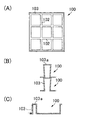
例えば電子部品などの生産工程で使用される収納トレー100として、図23に示されるように、縦横のリブ102で仕切られた物品収納部101の周囲が外周リブ103で囲われ、この外周リブ103を、当該リブの上面103aの幅がその下端開口部の幅よりも幅広となる逆テーパ状の断面形状に設けて形成されており、収納トレー100を上下に重ねた際に、上段の収納トレー100の外周リブ103の下端部が下段の収納トレー100の外周リブ103の上面に当接することで外周リブ103の没入を防止し、収納トレー100、100同士を上下多段に積み重ねることができるように構成されたものが知られている(例えば特許文献1、2、3参照)。
For example, as a
ところで、電子部品などの生産工程において、収納トレーを同方向に向けて積み重ねることができれば、収納作業における人為的ミスが生じ難く、収納トレーに電子部品の向きを揃えて収納し保管や運搬に供することが可能である。
前記図23に示された収納トレー100は、収納トレー100同士を同方向に向けて積み重ねることができるものの、収納する電子部品が重量物である場合や収納トレー100を多段に積み重ね過ぎた場合には、同図(C)に示されるように、上段の収納トレー100から受ける下向きの荷重によって外周リブ103の縁辺部が外側へ逃げる如く広がって変形してしまい易いという問題があった。
電子部品を含む各種物品の運搬に用いられるこの種の収納トレーは、軽量化や材料費削減の要請から合成樹脂材料の薄肉化を図るべく開発が進められているが、合成樹脂材を薄くすると強度が低下することから、薄肉であっても強度を維持できる構造が望まれる。前記逆テーパ状の外周リブ103の傾斜角度を大きく確保できれば強度は高まるが、それでは成型金型のコストが高くなってしまう。
By the way, if the storage trays can be stacked in the same direction in the production process of electronic parts and the like, human errors in the storage work are unlikely to occur, and the electronic parts are stored in the storage tray in the same direction for storage and transportation. It is possible.
The
This type of storage tray used for transporting various items including electronic parts is being developed to reduce the thickness of synthetic resin materials due to demands for weight reduction and material cost reduction. Since the strength is lowered, a structure capable of maintaining the strength even if it is thin is desired. If the inclination angle of the reverse-tapered outer
本発明は従来技術の有するこのような問題点に鑑み、合成樹脂薄板の真空成形体からなる収納トレーにおいて、トレー全体を薄肉に成形しても所望の強度を維持して、物品を収納したトレーを同方向に向けて上下多段に積み重ねて保管や運搬などに供することができるようにすることを課題とする。 SUMMARY OF THE INVENTION In view of the above-described problems of the prior art, the present invention is a storage tray made of a synthetic resin thin plate vacuum molded body, which maintains the desired strength even when the entire tray is molded thin, and stores articles. It is an object of the present invention to stack them in the upper and lower stages in the same direction so that they can be stored and transported.
前記課題を解決するため本発明は、物品収納部の周囲が、収納部から立ち上がって外方へ張り出した平坦部と平坦部から下向きに折れて斜め下方へ拡開した外壁部からなる側枠部で囲われてなる合成樹脂薄板の真空成形体よりなる収納トレーであって、前記側枠部に形成された複数のスタック部で同一方向に向けて重ねられた上段のトレーを下段のトレーが支持して上下に積み重ね可能に構成された収納トレーにおいて、
前記各スタック部は、側枠部の外面に形成された窪み部内に窪み部の底部から起立して前記平坦部に連なる細柱部が設けられているとともに、当該細柱部はその下部両側面に内方へ凹んだ凹面部をそれぞれ設けて形成された構成を有することを特徴とする。
In order to solve the above-mentioned problem, the present invention provides a side frame portion including a flat portion that rises from the storage portion and protrudes outward from the storage portion, and an outer wall portion that folds downward from the flat portion and expands obliquely downward. A storage tray made of a synthetic resin thin plate vacuum molded body surrounded by a lower tray that supports an upper tray stacked in the same direction by a plurality of stack portions formed on the side frame portion. In the storage tray that can be stacked up and down ,
Wherein each stack portion together with Hosohashira portion continuous to the flat portion stands up from the bottom of the recess in the recess portion formed on an outer surface of the side frame portions are provided, the Hosohashira portion lower sides thereof It has the structure formed by providing the concave part recessed inward in each, It is characterized by the above-mentioned.
前記構成の収納トレーによれば、収納トレー同士を同方向に向けて重ね合わせた状態で、下段のスタック部の細柱部の上端が、上段のスタック部の細柱部の下端に接合することで、上下の収納トレーを一定の間隔を保持して積み重ねることができる。
上下に重なったスタック部で接合する細柱部は、その下部両側面に凹面部がそれぞれ形成され、細柱部の両側面間の間隔がその上部よりも下部の方が小さくなるように設けてあるので、下段の細柱部の上端は上段の細柱部の細幅の下端部に当接して支持され、下段の細柱部が上段の細柱部内に没入し難くなっている。また、各スタック部に細柱部を設けることで側枠部が補強されて外側へ開き難くなり、段積みした収納トレーに大きな衝撃が加わったときは上下の細柱部が互いに上下端部を接合させたままトレーの外周方向に互いに滑ることで衝撃を吸収し、これにより側枠部が外側へ開いてしまうなどの変形を来し難くなる。
According to the storage tray having the above configuration, the upper ends of the thin column portions of the lower stack portion are joined to the lower ends of the thin column portions of the upper stack portion in a state where the storage trays are overlapped in the same direction. Thus, the upper and lower storage trays can be stacked while maintaining a certain interval.
The narrow pillars joined by the stacks that overlap each other are provided with concave parts on both sides of the lower part so that the distance between both sides of the fine pillars is smaller in the lower part than in the upper part. Therefore, the upper end of the lower fine column portion is supported by being in contact with the narrow lower end portion of the upper fine column portion, and the lower fine column portion is difficult to be immersed in the upper fine column portion. In addition, by providing the narrow column part in each stack part, the side frame part is reinforced and it is difficult to open to the outside, and when a large impact is applied to the stacked storage tray, the upper and lower fine column parts mutually connect the upper and lower ends. While being joined, the impact is absorbed by sliding on each other in the outer peripheral direction of the tray, thereby making it difficult for deformation such as the side frame portion to open outward.
前記構成の収納トレーにおいて、細柱部の下部両側面と窪み部の底部とがそれぞれテーパ部で連なり、両テーパ部の上方の細柱部の両側面に凹面部をそれぞれ設けて形成された構成を有することが好ましい。
細柱部の下部両側面を、テーパ部を介して窪み部の底部に接続することで、両テーパ部の上方に設ける凹面部を適宜な肉厚を確保して成形することができ、また、細柱部の下部両側にテーパ部を設けることで、収納トレーを段積みした際に下段の収納トレーの細柱部を上段の収納トレーのテーパ部下面に沿って上下の細柱部同士の係合位置に正確に案内することが可能である。
In the storage tray having the above-described configuration, the lower side surfaces of the narrow column portion and the bottom portion of the recess portion are connected by taper portions, respectively, and the concave surface portions are provided on both side surfaces of the narrow column portion above both taper portions. It is preferable to have.
By connecting the lower both side surfaces of the narrow pillar part to the bottom part of the hollow part via the taper part, the concave surface part provided above both taper parts can be molded while ensuring an appropriate thickness, By providing tapered portions on both sides of the lower column, when the storage trays are stacked, the narrow columns of the lower storage tray are connected to each other along the lower surface of the upper storage tray. It is possible to accurately guide to the matching position.
また、前記構成の収納トレーにおいて、窪み部内に複数の細柱部が適宜な間隔を開けて設けられた構成を有することが好ましい。
窪み部内に細柱部を設けることによって側枠部の強度が増して外周に開き難くなるが、細柱部を複数本、少なくとも一対を適宜な間隔を開けて設ければ、収納トレーに重量物を載せた際に側枠部を作用する開く方向への応力に対し、各細柱部同士が相互に引き合うように作用して側枠部の開きを防止し、側枠部の強度をより高めることができる。
Further, the storage tray having the above-described configuration preferably has a configuration in which a plurality of fine column portions are provided at appropriate intervals in the recess portion.
By providing the narrow column in the recess, the strength of the side frame is increased and it is difficult to open it to the outer periphery. However, if multiple thin columns and at least one pair are provided at an appropriate interval, a heavy load is placed on the storage tray. Against the stress in the opening direction that acts on the side frame when it is placed, the narrow pillars act so as to attract each other to prevent the opening of the side frame, and further increase the strength of the side frame be able to.
また、本発明は、物品収納部の周囲が平坦部と外壁部からなる側枠部で囲われてなり、前記側枠部の外周面に複数のスタック部が設けられた合成樹脂薄板の真空成形体よりなる皿状の収納トレーにおいて、
前記各スタック部は、前記側枠部の外周面に形成された窪み部内に設けられており、前記平坦部に連ねて窪み部内に設けられた細柱部と、当該細柱部の下部両側面と前記窪み部の底部の間に設けられたテーパ部と、前記細柱部の下部両側面であって前記両テーパ部の上方に設けられた内方へ凹んだ凹面部とを備えて形成されているとことを特徴とする。
Further, the present invention provides a vacuum forming of a synthetic resin thin plate in which the periphery of the article storage portion is surrounded by a side frame portion including a flat portion and an outer wall portion, and a plurality of stack portions are provided on the outer peripheral surface of the side frame portion. In a dish-shaped storage tray made of body,
Each of the stack portions is provided in a hollow portion formed on the outer peripheral surface of the side frame portion, and a thin column portion provided in the hollow portion in a row with the flat portion, and both lower side surfaces of the thin column portion And a tapered portion provided between the bottom portion of the hollow portion, and a concave portion recessed inwardly provided on both lower side surfaces of the thin column portion and above the tapered portion. It is characterized by being.
さらに、本発明の他の態様として、物品収納部の周囲が平坦部と外壁部からなる側枠部で囲われてなり、前記物品収納部の内周面に複数のスタック部が設けられた合成樹脂薄板の真空成形体よりなる皿状の収納トレーにおいて、
前記各スタック部は、前記物品収納部の内周面に設けられており、前記物品収納部の底面から立設した細柱部と、当該細柱部の上部両側面と前記平坦部の間に設けられたテーパ部と、前記細柱部の上部両側面であって前記両テーパ部の下方に設けられた、細柱部の内面間隔が狭まる向きに突出した凹面部とを備えて形成されているとことを特徴とする。
Furthermore, as another aspect of the present invention, the article storage portion is surrounded by a side frame portion including a flat portion and an outer wall portion, and a plurality of stack portions are provided on the inner peripheral surface of the article storage portion. In a dish-shaped storage tray consisting of a vacuum molded body of resin thin plate,
Each of the stack portions is provided on an inner peripheral surface of the article storage portion, and is provided between a thin column portion erected from the bottom surface of the article storage portion, an upper side surface of the fine column portion, and the flat portion. The taper portion is provided, and is provided on both upper side surfaces of the thin column portion and below the both taper portions, and is formed with a concave surface portion projecting in a direction in which the interval between the inner surfaces of the narrow column portions is narrowed. It is characterized by being.
またさらに、本発明の他の態様として、物品収納部の周囲を底面から上方へ立ち上げた側壁部で囲い、側壁部の上端に外方へ張り出した平坦部を設けてなる合成樹脂薄板の真空成形体よりなる皿状の収納トレーであって、前記側壁部の上部に形成された複数のスタック部で同一方向に向けて重ねられた上段のトレーを下段のトレーが支持して上下に積み重ね可能に構成された収納トレーにおいて、
前記各スタック部は、前記側壁部の上部から平坦部に亘って形成された窪み部内に、窪み部の底部から起立して前記平坦部に連なる複数の細柱部が適宜な間隔を開けて設けられ、且つ各細柱部はその下部両側面と前記窪み部の底部との間にテーパ部が設けられた構成を有することを特徴とする。
Furthermore, as another aspect of the present invention, a vacuum is applied to a synthetic resin thin plate in which the periphery of the article storage portion is surrounded by a side wall portion raised upward from the bottom surface, and a flat portion projecting outward is provided at the upper end of the side wall portion. A dish-shaped storage tray made of a molded body that can be stacked up and down with the lower tray supporting the upper tray stacked in the same direction at the stacks formed on the top of the side wall. In the storage tray configured in
Each of the stack portions is provided with a plurality of fine pillar portions standing at the bottom portion of the recess portion and connected to the flat portion at appropriate intervals in a recess portion formed from the upper portion of the side wall portion to the flat portion. In addition, each of the narrow pillar portions has a configuration in which a tapered portion is provided between both lower side surfaces thereof and the bottom portion of the hollow portion.
前記各構成の収納トレーによっても、物品を収納した収納トレー同士を、同方向に向けて、或いは異なる方向に向けて重ね合わせた状態で、下段のスタック部の細柱部の上端が、上段のスタック部の細柱部の下端に接合することで、上下の収納トレーを一定の間隔を保持して積み重ねることが可能である。 Even with the storage trays having the above-described configurations, the upper ends of the narrow column portions of the lower stack portion are in the state where the storage trays storing articles are stacked in the same direction or in different directions. By joining to the lower end of the narrow column portion of the stack portion, it is possible to stack the upper and lower storage trays while maintaining a certain interval.
本発明の収納トレーは、例えばポリエチレンテレフタレート(PET)やポリプロピレン、ポリスチレンなどの合成樹脂材を用い、薄いシート状の樹脂板を真空成形して形成することができる。成形材料はこれに限定されず他の適宜な樹脂材を用いてもよい。
前記細柱部は中空な板状突起であり、収納トレーの肉厚にもよるが、例えば両側面間の間隙(中空部間)を1〜10mm程度の太さに形成することができる。細柱部の両側面に設ける凹面部は、アンダーカット加工によって形成される内方へ逆テーパ状に凹んだ面であり、成形時の離型性を考慮して適宜な幅に凹ませて形成することができる。例えば両側面間の間隙を1.5mm程度に設けた細柱部の場合、凹面部は両側面から細柱部の内方へそれぞれ0.5〜0.75mmの幅だけ凹んだ大きさに設けることができる。また、両側面間の間隙が1〜4mm程度の太さの細柱部の場合に、両側面の凹面部が接し、つまり細柱部の下部両側面を貫通させた形状に設ければ、下段の細柱部を安定的に支持する上でより効果がある。
The storage tray of the present invention can be formed by using a synthetic resin material such as polyethylene terephthalate (PET), polypropylene, and polystyrene, and vacuum-forming a thin sheet-like resin plate. The molding material is not limited to this, and other appropriate resin materials may be used.
The narrow column portion is a hollow plate-like protrusion, and depending on the thickness of the storage tray, for example, a gap between both side surfaces (between the hollow portions) can be formed to a thickness of about 1 to 10 mm. Concave parts provided on both side surfaces of the narrow column part are inwardly tapered surfaces formed by undercut processing, and are formed by indenting to an appropriate width in consideration of releasability during molding. can do. For example, in the case of a thin column portion provided with a gap between both side surfaces of about 1.5 mm, the concave surface portion is provided in a size recessed by a width of 0.5 to 0.75 mm from the both side surfaces to the inside of the thin column portion. be able to. In addition, in the case of a thin column part having a thickness of about 1 to 4 mm between both side surfaces, if the concave surface part of both side surfaces are in contact with each other, that is, if the lower side surfaces of the thin column part are penetrated, the lower stage It is more effective in stably supporting the thin column part.
また、物品収納部の内周面に窪み部を設け、この窪み部内に、前記平坦部に連なる細柱部と、当該細柱部の下部両側面と前記窪み部の底部の間に設けられたテーパ部と、前記細柱部の下部両側面であって前記両テーパ部の上方に設けられた内方へ凹んだ凹面部とを備えたスタック部を設けてもよい。
なお、収納トレーに設ける前記スタック部の位置や個数、スタック部を構成する窪み部の幅や深さ、窪み部内に設ける細柱部の大きさや数などは、収納する物品の重量や形状などに応じて設計される収納トレーの成形寸法、成形材料、成形条件などに応じて適宜に選定可能である。物品収納部の内周面にスタック部を設ける場合も、その位置や個数、細柱部の大きさや数などを、上記と同様の条件に応じて適宜に選定可能である。
In addition, a recess is provided on the inner peripheral surface of the article storage unit, and the narrow column connected to the flat portion is provided between the lower side surfaces of the narrow column and the bottom of the recess in the recess. You may provide the stack part provided with the taper part and the concave part which was indented inward provided in the lower both sides | surfaces of the said thin pillar part above the said taper part.
In addition, the position and number of the stack portions provided in the storage tray, the width and depth of the recess portions constituting the stack portion, the size and number of the narrow pillar portions provided in the recess portions, and the like depend on the weight and shape of the articles to be stored. The storage tray can be appropriately selected according to the molding dimensions, molding material, molding conditions, etc. of the storage tray designed accordingly. Even when the stack portion is provided on the inner peripheral surface of the article storage portion, the position and number thereof, the size and number of the thin column portions, and the like can be appropriately selected according to the same conditions as described above.
本発明の好適な一実施形態を、図面を参照して説明する。
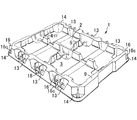
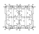
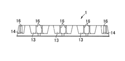
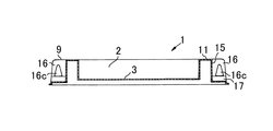
図1〜図3は本発明の第1実施形態の収納トレーの外観斜視図、平面図、正面図をそれぞれ示しており、この収納トレー1は、シート状のPETを真空成形により成形し、物品が収納される物品収納部2の周囲を側枠部9で囲って方形皿状に形成されている。
A preferred embodiment of the present invention will be described with reference to the drawings.
1 to 3 show an external perspective view, a plan view, and a front view of the storage tray according to the first embodiment of the present invention. The
詳しくは、物品収納部2は全体として平面視略矩形状を呈し、その底面3内が当該収納部の中心を通って長手方向に連なったリブ4と同じく短手方向に連なったリブ5とで四つの収納領域6に区画されているとともに、各収納領域6の四隅部に各々底面3よりも下方へ、深く凹んだ凹部7と浅く凹んだ凹部8とが配置された形状に設けられている。
Specifically, the
側枠部9は、物品収納部2の周辺縁に沿って連なった断面略々下向きコ字状の枠状部であり、物品収納部2の底面3の縁部から上方へ略垂直に立ち上がった内壁部10と、内壁部10の上端で略水平に折れて外方へ張り出した平坦部11と、平坦部11の外端部から下向きに折れて斜め下方へ拡開した外壁部12とにより形成されており、収納トレー1の対向長手二辺を構成する側枠部9にはそれぞれ三つのスタック部13が、また、四隅コーナー部を構成する側枠部9にはスタック部14が各々設けられている。
The
収納トレー1の対向長手二辺に設けられた三つのスタック部13は、それぞれ長手辺の中央部と当該中央部から両側の短手辺に向けて等間隔に離間させた位置に配置されており、各スタック部13は、側枠部9の外面に形成された窪み部15内に二本の細柱部16、16を設けて形成されている。
The three
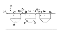
より詳しくは、図4に示されるように、窪み部15は、平坦部11から下向きに略垂直に折れた外面部15aと外面部15aの下端から略水平に折れて外壁部12に連なる底部15bとにより、側枠部9の平坦部11の上面から外壁部12に亘って適宜な幅及び深さで切り欠いた形状に設けられており、二本の細柱部16、16はそれぞれ窪み部15の中央から等間隔離した位置に一体に設けてある。
More specifically, as shown in FIG. 4, the recessed
細柱部16は、窪み部15の底部15bに連なって底部15bの上方へ略垂直に起立していて、その上端16aを平坦部11に略水平に連ねて窪み部15の外面部15aから細幅を保持して収納トレー1の外周面に略直交する方向へ突出した中空な板状突起であり、その両側面16b、16bの下部がテーパ部17、17を介して窪み部15の底部15bに接続されているとともに、両テーパ部17、17が接続した部分よりも若干上方の位置に凹面部16c、16cを設けて形成されている。
細柱部16の両側面16b、16bに設けた凹面部16c、16cは、金型のアンダーカット加工によって両側面16b、16bを内方へ逆テーパ状に凹ませた部分であり、図5に示されるように、両側面16b、16b間の間隙はその上端16aの間隙Dhよりも凹面部16c、16cの間隙Dlの方が幅狭となるように形成されている。
なお、図4に示されるように、二本の細柱部16、16の間の外壁部12には凹リブ18が設けてある。
The
The
As shown in FIG. 4, a
また、収納トレー1の四隅コーナー部に設けられたスタック部14は、前記と同様に、コーナー部の側枠部9に設けられた窪み部15内に対角方向に沿って一本の細柱部16を一体に突出させて設けられている。四隅コーナー部の細柱部16が、テーパ部17、17を介して窪み部15の底部15bに接続され、両テーパ部17、17が接続した部分よりも若干上方の位置に凹面部16c、16cが形成されている点も前記と同様である。
In addition, the
このように構成された本形態の収納トレー1は、水平な支持面上に収納トレー1を載せれば、物品収納部2内の凹部7と側枠部9の外壁部12の下端部が支持面に当接して物品収納部2の底面3が水平に保持され、前記各収納領域6内に収納した物品を底面3上で水平に支持することができる。
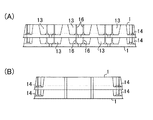
収納トレー1に物品を収納し、これを多段に重ねて保管するときは、図7に示されるように、下段の収納トレー1上に上段の収納トレー1を重ねれば、上段の収納トレーの外壁部12の内周面が下段の収納トレー1の外壁部12の外周面に被さり、さらに、上下の収納トレー1、1の対向長手辺の各スタック部13、13と四隅コーナー部の各スタック部14、14とが重なり、各スタック部の上下端部が噛み合って上下の収納トレー1、1間で一定の間隔を確保したまま位置をずらさずに安定的に積み重ねることが可能である。
In the
When the articles are stored in the
すなわち、図6に示されるように、収納トレー1、1同士を上下に重ね合わせた状態で、下段の収納トレー1のスタック部13の細柱部16の上端16aが、上段の収納トレー1のスタック部13のテーパ部17、17の下部に係入して当該テーパ部17、17間の細柱部16の下端に嵌合し、下段の収納トレー1の各細柱部16が当該嵌合位置に位置決めされる。
この際、各細柱部16はその両側面16b、16bの下部に凹面部16c、16cを設けて細柱部16の下端部の間隙を狭め、且つこれにより細柱部16の屈曲強度が高まり、下段の細柱部16が上段の細柱部16内に没入したり潰れたりするようなことはない。また、側枠部9にスタック部13、14をそれぞれ複数設け、各スタック部に外方へ突出した細柱部16を設けることで、側枠部9が補強されて変形が生じ難くなり、段積みした下段の収納トレー1に大きな重量が加わっても、側枠部9が外側へ開いてしまうなどの変形を来すことはない。
さらに、収納トレー1の対向長手側辺における側枠部9の対応位置に各スタック部13を設けてあるので、収納トレー1は同方向でも向きが逆であっても多段に安定して積み重ねることが可能である。
That is, as shown in FIG. 6, the upper ends 16 a of the
At this time, each
Further, since each
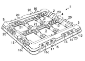
図8〜図11は本発明の第2実施形態の収納トレーを示しており、この収納トレー1は、前記形態と同様にシート状のPETを真空成形して方形皿状に形成されており、物品収納部2の周囲を囲う側枠部9の短手、長手両辺の外周面に各々スタック部19を設けて構成したものである。
FIGS. 8-11 has shown the storage tray of 2nd Embodiment of this invention, and this
詳しくは、各スタック部19の構成は前記形態と同様であり、側枠部9の外面に窪み部15を形成し、この窪み部15内に、平坦部11に連なる細柱部16を立設するとともに、細柱部16の下部両側面と窪み部15の底部の間にテーパ部17、17を設け、細柱部16の下部両側面であって両テーパ部17、17の上方に内方へ凹んだ凹面部16c、16cを設けて形成してある。
側枠部9の周辺に形成された各窪み部15は、各々収納トレー1の四隅コーナー部を除いて、長手辺と短手辺の略全体に亘る長さに設けられており、長手両辺の窪み部15内には五本の細柱部16を等間隔空けて配置し、短手両辺の窪み部15内には四本の細柱部16を等間隔空けて配置してある。
In detail, the structure of each
Each
このように構成された本形態の収納トレー1は、前記形態と同様に、収納トレー1に物品を収納し、これを上下に重ねれば、図11に示されるように、下段の収納トレー1のスタック部19の細柱部16の上端16aが、上段の収納トレー1のスタック部19のテーパ部17、17の下部に係入して当該テーパ部17、17間の細柱部16の下端に嵌合し、下段の各細柱部16が当該嵌合位置に位置決めされ、上下の収納トレー1、1のスタック部19、19の上下端部が噛み合って、上下の収納トレー1、1間で一定の間隔を確保したまま位置をずらさずに安定的に積み重ねることが可能である。
The
図12及び図13は本発明の第3実施形態の収納トレーを示しており、この収納トレー1は、前記形態と同様にシート状のPETを真空成形して方形皿状に形成されており、側枠部9の四側辺の外周面に各々二つのスタック部20を設けるとともに、物品収納部2の内周面と物品収納部2内を区画するリブ4の内面にも複数のスタック部21を設けて構成したものである。
12 and 13 show a storage tray according to a third embodiment of the present invention, and this
詳しくは、スタック部20は、側枠部9の各辺の中央からコーナー部側へ等間隔空けて二つ設けられており、前記形態と同様に、側枠部9の外面に形成された窪み部15内に、平坦部11に連なる細柱部16を立設し、細柱部16の下部両側面と窪み部15の底部の間にテーパ部17、17を設けるとともに、細柱部16の下部両側面であって両テーパ部17、17の上方に内方へ凹んだ凹面部16c、16cを設けて形成してある。各スタック部20には、3本の細柱部16を等間隔空けて配置してある。
また、スタック部21は、物品収納部2の内面と当該物品収納部2内を区画するリブ4の内面に窪み部15をそれぞれ形成し、前記形態と同様に、各窪み部15内に平坦部11に連なる細柱部16を立設し、細柱部16の下部両側面と窪み部15の底部の間にテーパ部17、17を設けるとともに、細柱部16の下部両側面であって両テーパ部17、17の上方に内方へ凹んだ凹面部16c、16cを設けて形成してある。各スタック部21には、2本の細柱部16を配置してある。
Specifically, two
Moreover, the
このように構成された本形態の収納トレー1によっても、前記形態と同様に、収納トレー1に物品を収納し、これを上下に重ねれば、上下の収納トレー1、1のスタック部20、20及びスタック部21、21の上下端部が噛み合って、上下の収納トレー1、1間で一定の間隔を確保したまま位置をずらさずに安定的に積み重ねることが可能である。
Also with the
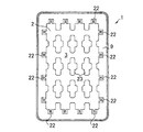
図14〜図18は本発明の第4実施形態の収納トレーを示しており、この収納トレー1は、前記形態と同様にシート状のPETを真空成形して方形皿状に形成されており、物品収納部2の内周面に複数のスタック部22を設けて構成したものである。
FIGS. 14-18 has shown the storage tray of 4th Embodiment of this invention, and this
詳しくは、物品収納部2内は、収納トレー1の底面2から立設させて複数の突部23によって格子状の収納空間に仕切られているとともに、物品収納部2内の長手両辺に沿った内面と短手両辺に沿った内面とに各々に四つスタック部22を設けてある。
各スタック部22は、図16及び図17に示されるように、物品収納部2の底面3から細柱部16を立設させ、この細柱部16の上部両側面と収納トレー1の上面である平坦部11とをテーパ部17、17を介して連ねるとともに、細柱部16の上部両側面であって両テーパ部17、17の下方に、細柱部16の内面間が狭まるよう向きに突出した凹面部16c、16cを設けて形成してある。
Specifically, the inside of the
As shown in FIGS. 16 and 17, each
このように構成された本形態の収納トレー1は、物品を収納した収納トレー1同士を上下に重ねれば、図18に示されるように、上段の収納トレー1のスタック部22の細柱部16の下端が、下段の収納トレー1のスタック部22のテーパ部17、17の上部に係入して当該テーパ部17、17間の細柱部16の上端に嵌合し、上段の収納トレー1の各細柱部16が当該嵌合位置に位置決めされて、上下の収納トレー1、1の各スタック部22同士が重なり、且つ上下のスタック部22、22の上下端部が噛み合って、上下の収納トレー1、1間で一定の間隔を確保したまま位置をずらさずに安定的に積み重ねることが可能である。
The
図19〜図22は本発明の第5実施形態の収納トレーを示しており、この収納トレー1は、前記形態と同様にシート状のPETを真空成形して方形皿状に形成されており、物品収納部2の周囲を囲う側壁部23の上部に沿って複数のスタック部25を設けて構成したものである。
19 to 22 show a storage tray according to a fifth embodiment of the present invention, and this
詳しくは、本形態の収納トレー1は物品収納部2が全体として平面視略矩形状を呈する浅底のトレーであり、前記物品収納部2の周囲を底面3から斜め上方へ立ち上げた側壁部23で囲い、側壁部23の上端を適宜な幅で外方へ水平に張り出した平坦部24とするとともに、物品収納部2が面する前記側壁部23の四側周辺部の各辺の中央にスタック部25を各々設けて形成してある。
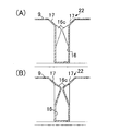
各スタック部25は、前記側壁部23の上部から平坦部24に亘って適宜な幅で下方へ凹ませてなる窪み部15内に、窪み部15の底部15bから起立して前記平坦部24に連なる二本の細柱部16、16を適宜な間隔を開けて設け、且つ両細柱部16、16はその両側面16b、16bと窪み部15の底部15bとの間にテーパ部17、17を設けて形成してある。
両細柱部16、16の上端16a、16a間及び細柱部16の上端16aと隣接する窪み部15の内面間は、平坦部24との境界部分が湾曲した開口部26としてある。この開口部26は、図20及び図21に示されるように、平坦部24に面する上部側が幅広、窪み部15の底部15bに面する下部が前記テーパ部17で囲われた幅狭となっている。また、収納トレー1の物品収納部2の四側辺を囲う側壁部23の四隅部は湾曲凹部27としてある。
Specifically, the
Each
Between the upper ends 16a, 16a of the two
本形態の収納トレー1は、前記各形態の収納トレー1と異なり、細柱部16の両側面に内方へ凹んだ凹面部16c、16cが設けられていないが、物品を収納した収納トレー1同士を上下に重ねれば、図22に示されるように、上段の収納トレー1が下段の収納トレー1の内側に嵌り込み、下段の収納トレー1のスタック部25の上面に上段の収納トレー1のスタック部25の下面が噛み合って係合し、上下の収納トレー1、1間で一定の間隔を確保したまま位置をずらさずに安定的に積み重ねることが可能である。
The
なお、図示した収納トレーは本発明の実施形態の一例を示すものであり、本発明の収納トレーはこれに限定されず、収納する物品の種類や大きさ、形状などに応じて適宜な形態で構成することが可能である。上述した実施の形態及び変形例の任意の組み合わせもまた本発明の実施の形態として有用である。組み合わせによって生じる新たな実施の形態は、組み合わされる実施の形態及び変形例それぞれの効果を併せ持つ。本発明は、電子部品などの各種部品類、各種用具や工具、日用品など様々な物品を収納するトレーに適用することが可能である。 Note that the illustrated storage tray is an example of an embodiment of the present invention, and the storage tray of the present invention is not limited to this, and in an appropriate form according to the type, size, shape, etc. of the articles to be stored. It is possible to configure. Any combination of the above-described embodiments and modifications is also useful as an embodiment of the present invention. The new embodiment generated by the combination has the effects of the combined embodiment and the modified examples. The present invention can be applied to a tray that stores various items such as electronic components, various tools and tools, daily goods, and the like.
1 収納トレー、2 物品収納部、3 底面、4、5 リブ、6 収納領域、7、8 凹部、9 側枠部、10 内壁部、11 平坦部、12 外壁部、13 スタック部、14 四隅スタック部、15 窪み部、16 細柱部、16c 凹面部、17 テーパ部、18 凹リブ、19,20,21,22 スタック部、23 側壁部、24 平坦部、25 スタック部、26 開口部、27 湾曲凹部
DESCRIPTION OF
Claims (5)
前記各スタック部は、側枠部の外面に形成された窪み部内に窪み部の底部から起立して前記平坦部に連なる複数の細柱部が設けられているとともに、前記細柱部はその下部両側面に内方へ凹んだ凹面部をそれぞれ設けて形成された構成を有することを特徴とする収納トレー。 Synthetic resin thin plate vacuum surrounding the article storage part surrounded by a side frame part consisting of a flat part rising from the storage part and projecting outward, and an outer wall part that folds downward from the flat part and expands obliquely downward It is a dish-shaped storage tray made of a molded body, and the upper tray stacked in the same direction by the plurality of stack portions formed on the side frame portion is supported by the lower tray so that it can be stacked vertically In the configured storage tray ,
Each of the stack portions is provided with a plurality of thin column portions standing from a bottom portion of the depression portion and connected to the flat portion in a depression portion formed on an outer surface of the side frame portion, and the fine column portion is provided at a lower portion thereof. A storage tray having a structure formed by providing concave portions recessed inward on both side surfaces .
前記各スタック部は、前記側枠部の外周面に形成された窪み部内に設けられており、前記平坦部に連ねて窪み部内に設けられた細柱部と、当該細柱部の下部両側面と前記窪み部の底部の間に設けられたテーパ部と、前記細柱部の下部両側面であって前記両テーパ部の上方に設けられた内方へ凹んだ凹面部とを備えて形成されているとことを特徴とする収納トレー。 The perimeter of the article storage part is surrounded by a side frame part composed of a flat part and an outer wall part, and is a dish-like shape made of a synthetic resin thin plate vacuum molded body provided with a plurality of stack parts on the outer peripheral surface of the side frame part. In the storage tray,
Each of the stack portions is provided in a hollow portion formed on the outer peripheral surface of the side frame portion, and a thin column portion provided in the hollow portion in a row with the flat portion, and both lower side surfaces of the thin column portion And a tapered portion provided between the bottom portion of the hollow portion, and a concave portion recessed inwardly provided on both lower side surfaces of the thin column portion and above the tapered portion. A storage tray characterized by
前記各スタック部は、前記物品収納部の内周面に設けられており、前記物品収納部の底面から立設した細柱部と、当該細柱部の上部両側面と前記平坦部の間に設けられたテーパ部と、前記細柱部の上部両側面であって前記両テーパ部の下方に設けられた、細柱部の内面間隔が狭まる向きに突出した凹面部とを備えて形成されているとことを特徴とする収納トレー。 A dish-like shape made of a synthetic resin thin plate vacuum molded body in which the periphery of the article storage portion is surrounded by a side frame portion composed of a flat portion and an outer wall portion, and a plurality of stack portions are provided on the inner peripheral surface of the article storage portion. In the storage tray of
Each of the stack portions is provided on an inner peripheral surface of the article storage portion, and is provided between a thin column portion erected from the bottom surface of the article storage portion, an upper side surface of the fine column portion, and the flat portion. The taper portion is provided, and is provided on both upper side surfaces of the thin column portion and below the both taper portions, and is formed with a concave surface portion projecting in a direction in which the interval between the inner surfaces of the narrow column portions is narrowed. A storage tray characterized by
Priority Applications (1)
| Application Number | Priority Date | Filing Date | Title |
|---|---|---|---|
| JP2011276882A JP5951978B2 (en) | 2010-12-21 | 2011-12-19 | Storage tray |
Applications Claiming Priority (5)
| Application Number | Priority Date | Filing Date | Title |
|---|---|---|---|
| JP2010284439 | 2010-12-21 | ||
| JP2010284439 | 2010-12-21 | ||
| JP2011112108 | 2011-05-19 | ||
| JP2011112108 | 2011-05-19 | ||
| JP2011276882A JP5951978B2 (en) | 2010-12-21 | 2011-12-19 | Storage tray |
Publications (3)
| Publication Number | Publication Date |
|---|---|
| JP2012254829A JP2012254829A (en) | 2012-12-27 |
| JP2012254829A5 JP2012254829A5 (en) | 2015-07-02 |
| JP5951978B2 true JP5951978B2 (en) | 2016-07-13 |
Family
ID=46364533
Family Applications (1)
| Application Number | Title | Priority Date | Filing Date |
|---|---|---|---|
| JP2011276882A Active JP5951978B2 (en) | 2010-12-21 | 2011-12-19 | Storage tray |
Country Status (3)
| Country | Link |
|---|---|
| JP (1) | JP5951978B2 (en) |
| KR (1) | KR20120070505A (en) |
| CN (2) | CN202295586U (en) |
Families Citing this family (12)
| Publication number | Priority date | Publication date | Assignee | Title |
|---|---|---|---|---|
| CN202295586U (en) * | 2010-12-21 | 2012-07-04 | 柏宝日本公司 | Collecting tray |
| CN103213719A (en) * | 2013-04-16 | 2013-07-24 | 苏州达方电子有限公司 | Tray and using method thereof |
| CN106415879B (en) * | 2014-06-03 | 2020-08-25 | 三星Sdi株式会社 | Battery tray |
| JP6320257B2 (en) * | 2014-09-18 | 2018-05-09 | テイ・エス テック株式会社 | Storage case |
| EP3569519B1 (en) | 2014-11-21 | 2021-03-10 | Intercontinental Great Brands LLC | Resealable package with improved contents accessibility |
| CN104843283A (en) * | 2015-05-25 | 2015-08-19 | 苏州工业园区捷泰包装材料有限公司 | Tray for electronic devices |
| CN105667949B (en) * | 2016-04-15 | 2018-07-03 | 武汉华星光电技术有限公司 | Liquid crystal panel-packaging box |
| JP2018202271A (en) * | 2017-05-30 | 2018-12-27 | 日本電産株式会社 | Cleaning holding tool |
| CN109335214A (en) * | 2018-11-30 | 2019-02-15 | 安庆华璟电子科技有限公司 | A kind of general vacuum formed box of FPC and processing method |
| JP7244064B2 (en) * | 2019-03-11 | 2023-03-22 | オオサキメディカル株式会社 | Tray for gauze counting |
| JP7297237B2 (en) * | 2019-04-25 | 2023-06-26 | 三甲株式会社 | Motor receiving tray and transfer set |
| CN113320799B (en) * | 2021-05-18 | 2022-12-06 | 深圳市国显科技有限公司 | Foolproof tray for loading display screen module |
Family Cites Families (12)
| Publication number | Priority date | Publication date | Assignee | Title |
|---|---|---|---|---|
| JP4106225B2 (en) * | 2002-03-20 | 2008-06-25 | サイデック株式会社 | Storage tray for electronic components |
| TW568092U (en) * | 2002-09-27 | 2003-12-21 | Shuen Gung Hang Co Ltd | Storage plate capable of stacking and resisting against depressing |
| TWM261461U (en) * | 2004-09-20 | 2005-04-11 | Hung Seng Entpr Co Ltd | Placement tray for flat board |
| TWM276032U (en) * | 2005-05-12 | 2005-09-21 | Jian-Liang Lin | Conveying mold plate of semi-product electronic parts easily in quality control |
| SG147355A1 (en) * | 2007-04-24 | 2008-11-28 | Peak Plastic & Metal Prod | Reinforced tray for delicate devices |
| CN101293576A (en) * | 2007-04-24 | 2008-10-29 | 必佳塑胶金属制品厂(国际)有限公司 | Enhancement type bracket tray for accurate device |
| CN102015465B (en) * | 2008-04-22 | 2013-06-05 | 夏普株式会社 | Tray |
| CN101665169A (en) * | 2008-09-04 | 2010-03-10 | 胜华科技股份有限公司 | Tray structure |
| JP2010120689A (en) * | 2008-11-21 | 2010-06-03 | Shin Etsu Polymer Co Ltd | Parts transferring plate and its coupling device |
| CN202295586U (en) * | 2010-12-21 | 2012-07-04 | 柏宝日本公司 | Collecting tray |
| JP2013049466A (en) * | 2011-08-31 | 2013-03-14 | Sanyu Kikaku:Kk | Storage tray |
| JP2013052907A (en) * | 2011-09-05 | 2013-03-21 | Seiko Epson Corp | Soft tray |
-
2011
- 2011-08-25 CN CN201120314059XU patent/CN202295586U/en not_active Expired - Fee Related
- 2011-08-25 CN CN2011102472592A patent/CN102556467A/en active Pending
- 2011-12-14 KR KR1020110134594A patent/KR20120070505A/en not_active Application Discontinuation
- 2011-12-19 JP JP2011276882A patent/JP5951978B2/en active Active
Also Published As
| Publication number | Publication date |
|---|---|
| CN202295586U (en) | 2012-07-04 |
| CN102556467A (en) | 2012-07-11 |
| KR20120070505A (en) | 2012-06-29 |
| JP2012254829A (en) | 2012-12-27 |
Similar Documents
| Publication | Publication Date | Title |
|---|---|---|
| JP5951978B2 (en) | Storage tray | |
| JP5698275B2 (en) | Lid and packaging container provided with the lid | |
| JP6713625B2 (en) | Packaging container | |
| JP2008044636A (en) | Storage tray | |
| JP4106225B2 (en) | Storage tray for electronic components | |
| JP2009166859A (en) | Storing box with variable partition and method for conveying article by storing box | |
| JP4616086B2 (en) | Panel-shaped article storage tray | |
| JP3181222U (en) | Packing material | |
| JP5139235B2 (en) | Packing materials and packaging | |
| JP2020109025A (en) | Packaging container | |
| JP2008174270A (en) | Returnable box | |
| JPH0352654Y2 (en) | ||
| JP3187874U (en) | Packing material and package | |
| JP3140941U (en) | Food container | |
| JP2012206725A (en) | Packaging material and package | |
| TWM551163U (en) | Space-sparing improved pallet structure | |
| JP2018140787A (en) | Resin molding | |
| JP2023067378A (en) | Inner liner for container | |
| JP4748596B2 (en) | Dunage | |
| JP2008273564A (en) | Carrying container | |
| JP4614338B2 (en) | Double-sided plastic bottle tray | |
| JP2017077899A (en) | Cushion tray for packaging | |
| JP2022075354A (en) | Packaging device | |
| JP3175035U (en) | Packaging that supports the corners of flat parts | |
| JP2005059931A (en) | Knockdown container and knockdown container unit |
Legal Events
| Date | Code | Title | Description |
|---|---|---|---|
| A621 | Written request for application examination |
Free format text: JAPANESE INTERMEDIATE CODE: A621 Effective date: 20141106 |
|
| A521 | Request for written amendment filed |
Free format text: JAPANESE INTERMEDIATE CODE: A523 Effective date: 20150515 |
|
| A977 | Report on retrieval |
Free format text: JAPANESE INTERMEDIATE CODE: A971007 Effective date: 20150703 |
|
| A131 | Notification of reasons for refusal |
Free format text: JAPANESE INTERMEDIATE CODE: A131 Effective date: 20150908 |
|
| A521 | Request for written amendment filed |
Free format text: JAPANESE INTERMEDIATE CODE: A523 Effective date: 20151109 |
|
| TRDD | Decision of grant or rejection written | ||
| A01 | Written decision to grant a patent or to grant a registration (utility model) |
Free format text: JAPANESE INTERMEDIATE CODE: A01 Effective date: 20160510 |
|
| A61 | First payment of annual fees (during grant procedure) |
Free format text: JAPANESE INTERMEDIATE CODE: A61 Effective date: 20160609 |
|
| R150 | Certificate of patent or registration of utility model |
Ref document number: 5951978 Country of ref document: JP Free format text: JAPANESE INTERMEDIATE CODE: R150 |
|
| R250 | Receipt of annual fees |
Free format text: JAPANESE INTERMEDIATE CODE: R250 |
|
| R250 | Receipt of annual fees |
Free format text: JAPANESE INTERMEDIATE CODE: R250 |
|
| R250 | Receipt of annual fees |
Free format text: JAPANESE INTERMEDIATE CODE: R250 |
|
| R250 | Receipt of annual fees |
Free format text: JAPANESE INTERMEDIATE CODE: R250 |
|
| R250 | Receipt of annual fees |
Free format text: JAPANESE INTERMEDIATE CODE: R250 |