JP5949382B2 - Vehicle rear structure - Google Patents
Vehicle rear structure Download PDFInfo
- Publication number
- JP5949382B2 JP5949382B2 JP2012208482A JP2012208482A JP5949382B2 JP 5949382 B2 JP5949382 B2 JP 5949382B2 JP 2012208482 A JP2012208482 A JP 2012208482A JP 2012208482 A JP2012208482 A JP 2012208482A JP 5949382 B2 JP5949382 B2 JP 5949382B2
- Authority
- JP
- Japan
- Prior art keywords
- vehicle
- panel
- reinforcement
- joined
- partition
- Prior art date
- Legal status (The legal status is an assumption and is not a legal conclusion. Google has not performed a legal analysis and makes no representation as to the accuracy of the status listed.)
- Active
Links
Images


Classifications
-
- B—PERFORMING OPERATIONS; TRANSPORTING
- B62—LAND VEHICLES FOR TRAVELLING OTHERWISE THAN ON RAILS
- B62D—MOTOR VEHICLES; TRAILERS
- B62D25/00—Superstructure or monocoque structure sub-units; Parts or details thereof not otherwise provided for
- B62D25/08—Front or rear portions
- B62D25/087—Luggage compartments
-
- B—PERFORMING OPERATIONS; TRANSPORTING
- B60—VEHICLES IN GENERAL
- B60G—VEHICLE SUSPENSION ARRANGEMENTS
- B60G11/00—Resilient suspensions characterised by arrangement, location or kind of springs
- B60G11/14—Resilient suspensions characterised by arrangement, location or kind of springs having helical, spiral or coil springs only
- B60G11/16—Resilient suspensions characterised by arrangement, location or kind of springs having helical, spiral or coil springs only characterised by means specially adapted for attaching the spring to axle or sprung part of the vehicle
-
- B—PERFORMING OPERATIONS; TRANSPORTING
- B60—VEHICLES IN GENERAL
- B60G—VEHICLE SUSPENSION ARRANGEMENTS
- B60G15/00—Resilient suspensions characterised by arrangement, location or type of combined spring and vibration damper, e.g. telescopic type
- B60G15/02—Resilient suspensions characterised by arrangement, location or type of combined spring and vibration damper, e.g. telescopic type having mechanical spring
- B60G15/06—Resilient suspensions characterised by arrangement, location or type of combined spring and vibration damper, e.g. telescopic type having mechanical spring and fluid damper
- B60G15/067—Resilient suspensions characterised by arrangement, location or type of combined spring and vibration damper, e.g. telescopic type having mechanical spring and fluid damper characterised by the mounting on the vehicle body or chassis of the spring and damper unit
-
- B—PERFORMING OPERATIONS; TRANSPORTING
- B60—VEHICLES IN GENERAL
- B60G—VEHICLE SUSPENSION ARRANGEMENTS
- B60G21/00—Interconnection systems for two or more resiliently-suspended wheels, e.g. for stabilising a vehicle body with respect to acceleration, deceleration or centrifugal forces
- B60G21/02—Interconnection systems for two or more resiliently-suspended wheels, e.g. for stabilising a vehicle body with respect to acceleration, deceleration or centrifugal forces permanently interconnected
- B60G21/04—Interconnection systems for two or more resiliently-suspended wheels, e.g. for stabilising a vehicle body with respect to acceleration, deceleration or centrifugal forces permanently interconnected mechanically
- B60G21/05—Interconnection systems for two or more resiliently-suspended wheels, e.g. for stabilising a vehicle body with respect to acceleration, deceleration or centrifugal forces permanently interconnected mechanically between wheels on the same axle but on different sides of the vehicle, i.e. the left and right wheel suspensions being interconnected
- B60G21/051—Trailing arm twist beam axles
-
- B—PERFORMING OPERATIONS; TRANSPORTING
- B62—LAND VEHICLES FOR TRAVELLING OTHERWISE THAN ON RAILS
- B62D—MOTOR VEHICLES; TRAILERS
- B62D25/00—Superstructure or monocoque structure sub-units; Parts or details thereof not otherwise provided for
- B62D25/08—Front or rear portions
- B62D25/088—Details of structures as upper supports for springs or dampers
-
- B—PERFORMING OPERATIONS; TRANSPORTING
- B60—VEHICLES IN GENERAL
- B60G—VEHICLE SUSPENSION ARRANGEMENTS
- B60G2200/00—Indexing codes relating to suspension types
- B60G2200/20—Semi-rigid axle suspensions
- B60G2200/21—Trailing arms connected by a torsional beam, i.e. twist-beam axles
-
- B—PERFORMING OPERATIONS; TRANSPORTING
- B60—VEHICLES IN GENERAL
- B60G—VEHICLE SUSPENSION ARRANGEMENTS
- B60G2200/00—Indexing codes relating to suspension types
- B60G2200/20—Semi-rigid axle suspensions
- B60G2200/23—Trailing arms connected by a U-shaped torsion bar
-
- B—PERFORMING OPERATIONS; TRANSPORTING
- B60—VEHICLES IN GENERAL
- B60G—VEHICLE SUSPENSION ARRANGEMENTS
- B60G2204/00—Indexing codes related to suspensions per se or to auxiliary parts
- B60G2204/10—Mounting of suspension elements
- B60G2204/12—Mounting of springs or dampers
- B60G2204/124—Mounting of coil springs
- B60G2204/1246—Mounting of coil springs on twist beam axles
-
- B—PERFORMING OPERATIONS; TRANSPORTING
- B60—VEHICLES IN GENERAL
- B60G—VEHICLE SUSPENSION ARRANGEMENTS
- B60G2204/00—Indexing codes related to suspensions per se or to auxiliary parts
- B60G2204/10—Mounting of suspension elements
- B60G2204/15—Mounting of subframes
-
- B—PERFORMING OPERATIONS; TRANSPORTING
- B60—VEHICLES IN GENERAL
- B60G—VEHICLE SUSPENSION ARRANGEMENTS
- B60G2206/00—Indexing codes related to the manufacturing of suspensions: constructional features, the materials used, procedures or tools
- B60G2206/01—Constructional features of suspension elements, e.g. arms, dampers, springs
- B60G2206/60—Subframe construction
-
- B—PERFORMING OPERATIONS; TRANSPORTING
- B62—LAND VEHICLES FOR TRAVELLING OTHERWISE THAN ON RAILS
- B62D—MOTOR VEHICLES; TRAILERS
- B62D21/00—Understructures, i.e. chassis frame on which a vehicle body may be mounted
- B62D21/09—Means for mounting load bearing surfaces
Description
本発明は、ショックアブソーバとショックアブソーバよりも車両前側に位置するコイルスプリングとを含む自動車の車両後部構造に関する。 The present invention relates to a vehicle rear structure of an automobile including a shock absorber and a coil spring located on the vehicle front side of the shock absorber.
リアシートの車両後側に、車両床面に略平行なパーティションパネルを配置し、車室空間と荷室空間とを仕切ったセダンタイプ又はハッチバックタイプの自動車が普及している。特許文献1、2に例示されるように、このような自動車では、パーティションパネルを通常リアホイールハウスに連結している。リアホイールハウスには、リアサスペンション機構が下側から連結される。かかるリアサスペンション機構には、ショックアブソーバおよびコイルスプリングを一体に組み合わせたもの、ショックアブソーバおよびコイルスプリングを別々に配置したものがある。 A sedan type or hatchback type vehicle in which a partition panel substantially parallel to the vehicle floor surface is arranged on the rear side of the rear seat and the vehicle compartment space and the cargo compartment space are partitioned is widely used. As exemplified in Patent Documents 1 and 2, in such an automobile, a partition panel is usually connected to a rear wheel house. A rear suspension mechanism is connected to the rear wheel house from below. Such rear suspension mechanisms include those in which a shock absorber and a coil spring are combined together, and those in which a shock absorber and a coil spring are separately arranged.
ショックアブソーバおよびコイルスプリングを別々に配置したリアサスペンション機構、具体的にはショックアブソーバよりも車両前側にコイルスプリングが位置するようなリアサスペンション機構を採用した自動車では、ショックアブソーバおよびコイルスプリングそれぞれから入力される荷重に対し、充分な耐久性(剛性)を持たせる必要がある。しかし、車両重量の観点から、耐久性を確保するためにリンフォース等の補強部品を安易に追加するわけにはいかない。すなわち、車両重量の増加をなるべく抑えるため、効率よくリンフォースを配置して必要箇所の剛性を確保し、ショックアブソーバおよびコイルスプリングそれぞれから入力される荷重を効率よく伝達・分散できる構造が求められる。 For automobiles that employ a rear suspension mechanism in which a shock absorber and a coil spring are separately arranged, specifically, a rear suspension mechanism in which a coil spring is located on the front side of the vehicle relative to the shock absorber, input is made from the shock absorber and the coil spring, respectively. It is necessary to provide sufficient durability (rigidity) for the load to be applied. However, from the viewpoint of vehicle weight, reinforcement parts such as reinforcement cannot be easily added to ensure durability. That is, in order to suppress an increase in vehicle weight as much as possible, a structure is required that efficiently arranges the reinforcement to secure the rigidity of a necessary portion, and can efficiently transmit and disperse the load input from each of the shock absorber and the coil spring.
上記特許文献1、2に代表される従来技術では、パーティションパネルをリアホイールハウスに連結しているため、リアサスペンション機構からリアホイールハウスに伝達される荷重がパーティションパネルにも伝達・分散されるものの、荷重が効率よく伝達・分散される構造が実現されているとは言い難い。そもそも上記特許文献1、2においては、ショックアブソーバよりも車両前側にコイルスプリングが位置するようなリアサスペンション機構を採用した場合、すなわちショックアブソーバおよびコイルスプリングそれぞれから荷重が入力されるような場合について、特に考慮されていない。 In the prior art represented by the above Patent Documents 1 and 2, since the partition panel is connected to the rear wheel house, the load transmitted from the rear suspension mechanism to the rear wheel house is also transmitted and distributed to the partition panel. It is difficult to say that a structure that efficiently transmits and distributes loads is realized. First of all, in Patent Documents 1 and 2, when a rear suspension mechanism in which a coil spring is positioned on the front side of the vehicle with respect to the shock absorber, that is, when a load is input from each of the shock absorber and the coil spring, Not specifically considered.
本発明は、上記課題に鑑みてなされたものであり、ショックアブソーバおよびコイルスプリングそれぞれから入力される荷重を効率よく伝達・分散でき、車両重量の増加を抑えつつ充分な耐久性(剛性)を確保することができる車両後部構造を提供することを目的とする。 The present invention has been made in view of the above problems, and can efficiently transmit and disperse the load input from each of the shock absorber and the coil spring, and ensure sufficient durability (rigidity) while suppressing an increase in vehicle weight. An object of the present invention is to provide a vehicle rear structure that can be used.
上記課題を解決するために本発明の代表的な構成は、車両のタイヤを介して伝達される衝撃を吸収するコイルスプリングと、コイルスプリングの振動を減衰する伸縮式のショックアブソーバと、車両のタイヤの上側を包囲するアーチ形のリアホイールハウスであって上端部にショックアブソーバの上端を支持する座面を備えるリアホイールハウスとを含み、ショックアブソーバの車両前側にコイルスプリングが位置する車両後部構造において、リアシートの車両後側で車両床面に略平行に配置され車室空間と荷室空間とを仕切るパーティションパネルと、リアシートのシートバックに略平行なパネルであって上端にてパーティションパネルに接合され下端にてリアホイールハウスに座面の車両前側で接合されるパーティションサイドパネルと、パーティションサイドパネルと座面との間に立設される第1リンフォースであってコイルスプリングの上端に所定の要素を介して接続され、パーティションパネル、パーティションサイドパネルおよびリアホイールハウスにそれぞれ接合される第1リンフォースと、座面の車両後側に立設される第2リンフォースであってパーティションパネルおよびリアホイールハウスにそれぞれ接合される第2リンフォースとをさらに含むことを特徴とする。 In order to solve the above-described problems, a representative configuration of the present invention includes a coil spring that absorbs an impact transmitted through a vehicle tire, a telescopic shock absorber that attenuates vibration of the coil spring, and a vehicle tire. A rear wheel house that includes an arch-shaped rear wheel house that surrounds the upper side of the vehicle, and a rear wheel house that includes a seat surface that supports the upper end of the shock absorber at the upper end, and a coil spring located on the vehicle front side of the shock absorber. A partition panel arranged substantially parallel to the vehicle floor on the rear side of the rear seat and partitioning the compartment space and the cargo space, and a panel substantially parallel to the seat back of the rear seat and joined to the partition panel at the upper end. A partition side panel joined at the lower end to the rear wheel house on the vehicle front side of the seat surface; A first reinforcement erected between the partition side panel and the seating surface, connected to the upper end of the coil spring via a predetermined element, and joined to the partition panel, the partition side panel, and the rear wheel house, respectively. It further includes a first reinforcement and a second reinforcement that is erected on the rear side of the seating surface and that is joined to the partition panel and the rear wheel house, respectively.
上記構成によれば、コイルスプリングから入力される荷重(例えば突上荷重)は、座面の車両前側に立設されコイルスプリングの上端に所定の要素を介して接続される第1リンフォースを通じて、パーティションサイドパネルおよびパーティションパネルに伝達・分散される。またショックアブソーバから入力される荷重は、座面の車両前側に立設される第1リンフォースおよび座面の車両後側に立設される第2リンフォースを通じて、パーティションサイドパネルおよびパーティションパネルに伝達・分散される。これにより、ショックアブソーバおよびコイルスプリングそれぞれから入力される荷重を効率よく伝達・分散することができる。したがって、車両重量の増加を抑えつつ、充分な耐久性(剛性)を確保することができる。 According to the above configuration, the load (for example, the thrust load) input from the coil spring is provided through the first reinforcement that is erected on the vehicle front side of the seating surface and connected to the upper end of the coil spring via the predetermined element. It is transmitted and distributed to the partition side panel and partition panel. The load input from the shock absorber is transmitted to the partition side panel and the partition panel through the first reinforcement standing on the front side of the seat and the second reinforcement standing on the rear side of the seat.・ Distributed. Thereby, the load input from each of the shock absorber and the coil spring can be efficiently transmitted and distributed. Therefore, sufficient durability (rigidity) can be ensured while suppressing an increase in vehicle weight.
当該車両後部構造は、座面の上方で第1リンフォースと第2リンフォースとをつなぎさらにパーティションパネルに接合される第3リンフォースをさらに含むとよい。 The vehicle rear structure may further include a third reinforcement that connects the first reinforcement and the second reinforcement above the seating surface and is joined to the partition panel.
上記構成によれば、第3リンフォースによって、第1リンフォースと第2リンフォースとを補強することができる。これにより、コイルスプリング、ショックアブソーバから入力される荷重を伝達・分散する中心的な役割を果たす第1リンフォース、第2リンフォースの損傷、破壊を防止することができる。 According to the above configuration, the first reinforcement and the second reinforcement can be reinforced by the third reinforcement. Thereby, damage and destruction of the 1st reinforcement and the 2nd reinforcement which play a central role which transmits and distributes the load inputted from a coil spring and a shock absorber can be prevented.
当該車両後部構造は、車両床面を形成するリアフロアパネルと、第1リンフォースの下端とリアフロアパネルとをつなぐガセットと、リアフロアパネル下側に接合され車両前後方向に延びる断面視ハット型形状のリアサイドメンバであって、ガセットの下方に相当する位置にコイルスプリングが接合されるリアサイドメンバと、リアフロアパネルとリアサイドメンバとの閉断面構造内部に接合されるブレースであって、リアサイドメンバ底面に接合されるブレース底面と、ブレース底面から上方へと延びる起立面と、ブレース底面に略平行に起立面から延びガセットの下端およびリアフロアパネルが共に締結される締結面とを備えるブレースとをさらに含み、所定の要素は、リアサイドメンバ、ブレース、リアフロアパネルおよびガセットであるとよい。 The rear structure of the vehicle includes a rear floor panel that forms a vehicle floor, a gusset that connects the lower end of the first reinforcement and the rear floor panel, and a hat-shaped rear side that is joined to the lower side of the rear floor panel and extends in the vehicle front-rear direction. A rear side member, which is a member, and a coil spring is joined to a position corresponding to a lower part of the gusset, and a brace joined to the inside of a closed cross-sectional structure of the rear floor panel and the rear side member, and is joined to the bottom surface of the rear side member A brace comprising a brace bottom surface, a standing surface extending upward from the bottom surface of the brace, and a fastening surface extending substantially parallel to the bottom surface of the brace and extending from the standing surface to which the lower end of the gusset and the rear floor panel are fastened together. On the rear side members, braces, rear floor panels and gussets May that.
上記構成によれば、コイルスプリングから入力される荷重が、リアサイドメンバ、ブレース、リアフロアパネル、ガセットを通じて、第1リンフォースに伝達・分散される。これにより、コイルスプリングから入力される荷重を効率よく伝達・分散することができる。また、ガセットの下端をリアフロアパネルと共にブレースの締結面に締結することでこれらの結合強度を確保することができ、コイルスプリングからの突上荷重等に対する耐久性を確保することができる。 According to the above configuration, the load input from the coil spring is transmitted and distributed to the first reinforcement through the rear side member, the brace, the rear floor panel, and the gusset. Thereby, the load input from the coil spring can be efficiently transmitted and distributed. Further, by fastening the lower end of the gusset together with the fastening surface of the brace together with the rear floor panel, it is possible to secure these coupling strengths, and it is possible to ensure durability against a thrust load from the coil spring.
当該車両後部構造は、リアフロアパネル下側に接合される車両幅方向に延びるクロスメンバをさらに含み、リアフロアパネルは下方に凹んだスペアタイヤ収納部を備え、ブレースはリアサイドメンバ側面に接合されるブレース側面を備え、クロスメンバはスペアタイヤ収納部に接合されていて、クロスメンバの車両幅方向端部、およびリアサイドメンバの車両幅方向内側の側面は、ブレース側面に接合されているとよい。 The vehicle rear structure further includes a cross member extending in the vehicle width direction joined to the lower side of the rear floor panel, the rear floor panel includes a spare tire storage portion recessed downward, and the brace is joined to the side surface of the rear side member. The cross member may be joined to the spare tire storage portion, and the end of the cross member in the vehicle width direction and the side of the rear side member in the vehicle width direction may be joined to the side of the brace.
上記構成によれば、コイルスプリングから入力される荷重が、リアサイドメンバ、クロスメンバを通じて、車両幅方向に伝達・分散される。さらに、クロスメンバは下方に凹んだスペアタイヤ収納部にもつながっているため、スペアタイヤ収納部にも荷重が伝達・分散される。これによりコイルスプリングから入力される荷重を効率よく伝達・分散することができる。 According to the above configuration, the load input from the coil spring is transmitted and distributed in the vehicle width direction through the rear side member and the cross member. Further, since the cross member is also connected to the spare tire storage portion recessed downward, the load is transmitted and distributed to the spare tire storage portion. Thereby, the load input from the coil spring can be efficiently transmitted and distributed.
上記パーティションサイドパネルは、その車両幅方向外側寄りに形成された開口部を備え、第1リンフォースと車両側面との間および第2リンフォースと車両側面との間に空隙が確保されているとよい。 The partition side panel includes an opening formed on the outer side in the vehicle width direction, and a space is secured between the first reinforcement and the vehicle side surface and between the second reinforcement and the vehicle side surface. Good.
上記構成によれば、ハーネス等のケーブル類をパーティションサイドパネルの開口部に通すと共に、第1リンフォースと車両側面との間および第2リンフォースと車両側面との間に通し配線することができる。これにより、ハーネス等をリアフロアパネル上に固定する必要がないため、ハーネス等を固定するための部品(例えばクランプ)を設置するための孔をリアフロアパネルに開けずに済む。 According to the above configuration, cables such as a harness can be passed through the opening of the partition side panel, and can be wired between the first reinforcement and the vehicle side surface and between the second reinforcement and the vehicle side surface. . Thereby, since it is not necessary to fix a harness etc. on a rear floor panel, it is not necessary to open the hole for installing components (for example, clamp) for fixing a harness etc. in a rear floor panel.
本発明によれば、ショックアブソーバおよびコイルスプリングそれぞれから入力される荷重を効率よく伝達・分散でき、車両重量の増加を抑えつつ充分な耐久性(剛性)を確保することができる車両後部構造を提供することができる。 According to the present invention, there is provided a vehicle rear structure that can efficiently transmit and disperse a load input from each of the shock absorber and the coil spring, and can ensure sufficient durability (rigidity) while suppressing an increase in vehicle weight. can do.
以下に添付図面を参照しながら、本発明の好適な実施形態について詳細に説明する。かかる実施形態に示す寸法、材料、その他具体的な数値などは、発明の理解を容易とするための例示に過ぎず、特に断る場合を除き、本発明を限定するものではない。なお、本明細書および図面において、実質的に同一の機能、構成を有する要素については、同一の符号を付することにより重複説明を省略し、また本発明に直接関係のない要素は図示を省略する。 Hereinafter, preferred embodiments of the present invention will be described in detail with reference to the accompanying drawings. The dimensions, materials, and other specific numerical values shown in the embodiments are merely examples for facilitating understanding of the invention, and do not limit the present invention unless otherwise specified. In the present specification and drawings, elements having substantially the same function and configuration are denoted by the same reference numerals, and redundant description is omitted, and elements not directly related to the present invention are not illustrated. To do.
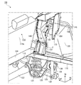
図1は、本発明による車両後部構造の実施形態である自動車100の車両右側面を斜め前方から見た図である。図中、「車両前側」を矢印Fwd、「車両右側」を矢印Rh、「車両上側」を矢印Upで表す。さらに図中、スポット溶接箇所172を図示し、代表して1つに符号を付す。ただし、スポット溶接箇所172は、必要のない部分については図示を省略する。
FIG. 1 is a view of a vehicle right side surface of an
図1に示すように、自動車100はセダンタイプの車両である。自動車100は、車両床面を形成するリアフロアパネル102を備える。リアフロアパネル102は、リアフロアフロントパネル104とリアフロアリアパネル106からなる。リアフロアリアパネル106は、車両幅方向略中央に下方に凹んだスペアタイヤ収納部108を備える。
As shown in FIG. 1, the
図2は、図1に示す部位からリアフロアパネル102を除いた図である。図2に示すように、リアフロアパネル102下側には、車両幅方向外側よりに、車両前後方向に延びる断面視ハット型形状(図7参照)のリアサイドメンバ110が接合される。また、リアフロアパネル102下側には、車両幅方向に延びるクロスメンバ112が接合される。クロスメンバ112は、その車両前側がリアフロアフロントパネル104とリアフロアリアパネル106とが重なる位置に位置するように接合される。
FIG. 2 is a view in which the
クロスメンバ112は、その後側がスペアタイヤ収納部108(図1参照)に沿って湾曲した形状をなす(以下この部分を「湾曲面114」と称する)。かかる湾曲面114は、スペアタイヤ収納部108に接合される。スペアタイヤ収納部108はリアフロアリアパネル106を下方に凹ませた部分であるため相対的に剛性が高い。したがって、これらを結合することで荷重に対して強い構造を実現することができる。
The
図3は、図1に示す自動車100の車両右側面を斜め後方から見た図である。図3に示すように、リアフロアフロントパネル104上には、リアシート116が設置される。かかるリアシート116の下方に相当する位置では、リアサイドメンバ110にリアサスペンションブラケット118が接合される。リアサスペンションブラケット118は、車両前後方向に延びる連結部材120の前端を回転可能に支持する。
FIG. 3 is a diagram of the right side surface of the
連結部材120は、車両幅方向に延びるトーションビーム122によって車両左側の連結部材と接続される。なお、本実施形態では、車両右側について説明するが、車両左側についても同様の説明が適用される。ただし車両左側は車両右側と対称である。
The connecting
自動車100は、図示省略するリアタイヤを介して伝達される衝撃を吸収するコイルスプリング124と、コイルスプリング124の振動を減衰する伸縮式のショックアブソーバ126とを備える。コイルスプリング124は、ショックアブソーバ126よりも車両前側に位置する。コイルスプリング124の下端は、連結部材120のトーションビーム122が接続される部分の後側に車両幅方向内側から取り付けられたコイルスプリング支持部材128によって支持される。
The
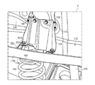
図4は、図3に示す範囲Zの拡大図である。図4に示すように、コイルスプリング124の上端は、コイルスプリングブラケット162を介してリアサイドメンバ底面110aに接続される。なお、コイルスプリング124の上端の上方には、リアフロアパネル102とリアサイドメンバ110との閉断面構造内部に接合されるブレース152、第1リンフォース156の下端とリアフロアパネル102とをつなぐガセット154等が備えられる(詳細については後述する)。
FIG. 4 is an enlarged view of the range Z shown in FIG. As shown in FIG. 4, the upper end of the
図3に示すように、ショックアブソーバ126は、その上端がリアタイヤの上側を包囲するアーチ形のリアホイールハウス130上端部(上部)の車両幅方向内側に形成された座面132に取り付けられる(支持される)。ショックアブソーバ126の下端は、連結部材120後端の車両幅方向内側から突出するピン134によって支持される。コイルスプリング支持部材128とピン134との間の連結部材120の車両幅方向外側には、リアタイヤを取り付けるためのリアタイヤ取付部材136が備えられる。
As shown in FIG. 3, the
自動車100では、効率よくリンフォースを配置して必要箇所の剛性を確保し、ショックアブソーバ126およびコイルスプリング124それぞれから入力される荷重(例えば突上荷重)を効率よく伝達・分散できる構造を実現している。以下、図1に示すパーティションパネル138およびパーティションサイドパネル140について説明した上で、かかる構造について具体的に説明する。
In the
図5は、図1に示すパーティションパネル138およびパーティションサイドパネル140の分解斜視図である。図5に示すように、パーティションパネル138は、パーティションパネル本体部142と、パーティションサイドエクステンション144と、パーティションサイドメンバ146とからなる。パーティションパネル138は、リアシート116の車両後側で、車両床面すなわちリアフロアリアパネル106に略平行に配置され車室空間168と荷室空間170とを仕切る(図1参照)。
FIG. 5 is an exploded perspective view of the
パーティションパネル本体部142は、平坦な平坦面142aと平坦面142aの前端から下降しさらに車両前側に延びる鉤状面142bとを備える。パーティションサイドエクステンション144はパーティションパネル本体部142の平坦面142aを延長したような形状をなし、平坦面142aの車両幅方向外側に接合される。パーティションサイドエクステンション144の車両幅方向外側は、車両右側面すなわちクォータパネル148に接合される。
The partition panel
パーティションサイドメンバ146は、パーティションパネル本体部142の鉤状面142bを延長したような形状をなし、鉤状面142bの車両幅方向外側に接合される。パーティションサイドメンバ146の車両幅方向外側は、車両右側面すなわちクォータパネル148に接合される。またパーティションサイドメンバ146の車両後側は、パーティションサイドエクステンション144に接合される。
The
パーティションサイドパネル140は、リアシート116のシートバック116aに略平行なパネルであって、車両幅方向外側よりに設置される(図1、図3参照)。図1に示すように、パーティションサイドパネル140は上端がパーティションパネル138に接合され、下端がリアホイールハウス130に座面132の車両前側で接合される。またパーティションサイドパネル140の車両幅方向外側は、車両右側面を形成するリアホイールハウス130およびクォータパネル148に接合される。
The
本実施形態では、パーティションサイドパネル140は、リアシート116のシートバック116aに略平行な前壁面140aと、前壁面140aの上辺とパーティションサイドメンバ146の上辺とをつなぎ閉断面構造を形成する天井面140bとからなる。パーティションパネル本体部142の鉤状面142bには、図5に仮想線で図示する鉤状面142bとの間で閉断面構造を形成するパーティションメンバ150が接合され、閉断面構造が車両幅方向において連続する。なお、パーティションサイドパネル140の前壁面140aは、側面視で下端から略鉛直に起立すると共に、途中から上方に延びるにつれて車両後側に傾斜する形状をなす。
In the present embodiment, the
図6は、図3に示すリアサイドメンバ110、ブレース152、ガセット154、第1リンフォース156、第2リンフォース158、第3リンフォース160の分解斜視図である。図6に示すように、自動車100は、コイルスプリング124の上端の上方に設置されるブレース152を備える。
6 is an exploded perspective view of the
図7は、図1のA−A断面図である。図7に示すように、ブレース152は、リアサイドメンバ底面110aに接合されるブレース底面152a、ブレース底面152aから上方へと延びる起立面152b、クロスメンバ112の車両幅方向端部がリアサイドメンバ110の車両幅方向内側の側面110bと共に接合されるブレース側面152cを備える。さらにブレース152は、ブレース底面152aに略平行に起立面152bから延びガセット154の下端がリアフロアパネル102と共に締結される締結面152dを備える。なお、起立面152b、ブレース側面152c、締結面152d等については代表して1つに符号を付す。
7 is a cross-sectional view taken along the line AA in FIG. As shown in FIG. 7, the
自動車100では、コイルスプリング124から入力される荷重を、リアサイドメンバ110、ブレース152、リアフロアパネル102(リアフロアフロントパネル104、リアフロアリアパネル106)、ガセット154を通じて、第1リンフォース156に伝達・分散する。本実施形態では、ガセット154の下端は、リアフロアフロントパネル104およびリアフロアリアパネル106を介して、ブレース152の締結面152dに4枚でボルト締結されるので、これらの結合強度を確保することができ、コイルスプリング124からの荷重に対する耐久性を確保することができる。さらに本実施形態では、ガセット154にビード形状(凹凸)を形成し、ガセット154の剛性を確保している。
In the
図3に示すように、第1リンフォース156はコイルスプリング124の上端の上方であって、パーティションサイドパネル140とリアホイールハウス130の座面132との間に立設される。第1リンフォース156の前端は、パーティションサイドパネル140の前壁面140aの車両幅方向内側の端部に概ね沿う形状をなし、これに背面側から接合される。第1リンフォース156の後端の一部は、リアホイールハウス130に接合される。第1リンフォース156の上端は、パーティションサイドメンバ146(パーティションパネル138)に下側から接合される。第1リンフォース156は、所定の要素であるリアサイドメンバ110、ブレース152、リアフロアパネル102、ガセット154を介して伝達される荷重をパーティションサイドパネル140およびパーティションサイドメンバ146(パーティションパネル138)に伝達・分散する。なお本実施形態では、パーティションサイドパネル140およびパーティションサイドメンバ146を閉断面構造とすることで剛性を確保している。
As shown in FIG. 3, the
図8は、図3のB−B断面図である。図8に示すように、第1リンフォース156は、パーティションサイドパネル140の前壁面140aとの間で略「コ」字形状の断面を形成する。ガセット154を通じて第1リンフォース156に伝達される荷重はパーティションサイドパネル140の前壁面140aに対してせん断方向となるため、効率よく荷重をパーティションサイドパネル140に伝達・分散することができる。すなわち本実施形態においてパーティションサイドパネル140の前壁面140aは、あたかも第1リンフォース156と一体の略「コ」字形状の断面を有するリンフォースのように機能するため、部品点数の削減を図ることができる。
8 is a cross-sectional view taken along the line BB in FIG. As shown in FIG. 8, the
図7に示すように、本実施形態ではクロスメンバ112の車両幅方向端部がリアサイドメンバ110の車両幅方向内側の側面110bおよびブレース側面152cに接続されるため、コイルスプリング124から入力される荷重はリアサイドメンバ110、クロスメンバ112を通じて、車両幅方向にも伝達・分散される。さらに、クロスメンバ112は下方に凹んだスペアタイヤ収納部108にもつながっているため(図1、2参照)、スペアタイヤ収納部108にも荷重が伝達・分散される。
As shown in FIG. 7, in this embodiment, the end of the
上述した構造によれば、コイルスプリング124から入力される荷重を円滑に各所に(上下方向、車両幅方向に)伝達・分散することができる。すなわち、コイルスプリング124から入力される荷重を効率よく伝達・分散することができる。これにより、車両重量の増加を抑えつつ、充分な耐久性(剛性)を確保することができる。なお本実施形態において、第1リンフォース156およびガセット154は、パーティションサイドパネル140の前壁面140a近傍に設置されているため、これらが荷室空間に過度に突出することはない。したがって、荷室空間の容量の確保の障害にはならない。
According to the structure described above, the load input from the
図3に示すように、第1リンフォース156の後端の一部はリアホイールハウス130の座面132の車両前側に接合されていて、ショックアブソーバ126上端に近接した位置にある。そのため、第1リンフォース156は、ショックアブソーバ126から入力される荷重をパーティションサイドパネル140、パーティションサイドメンバ146に伝達・分散する役割も果たす。よって、第1リンフォース156はコイルスプリング124だけでなくショックアブソーバ126から入力される荷重を伝達・分散するリンフォースとしての役割も果たすので、部品点数の削減および構造の簡素化を図ることができる。
As shown in FIG. 3, a part of the rear end of the
リアホイールハウス130の座面132の車両後側には第2リンフォース158が立設される。第2リンフォース158は、その上端がパーティションサイドメンバ146に接合され、その下端がリアホイールハウス130の座面132の車両後側に接合される。すなわち、第2リンフォース158はショックアブソーバ126上端に近接した位置にあり、ショックアブソーバ126から入力される荷重をパーティションサイドメンバ146に伝達・分散する。
A
したがって、ショックアブソーバ126から入力される荷重は、座面132の車両前側に立設される第1リンフォース156および座面132の車両後側に立設される第2リンフォース158を通じて、パーティションサイドパネル140およびパーティションパネル138に伝達・分散される。このような構造を採用することで、ショックアブソーバ126から入力される荷重を効率よく伝達・分散することができ、車両重量の増加を抑えつつ、充分な耐久性(剛性)を確保することができる。
Therefore, the load input from the
図3に示すように、第1リンフォース156と第2リンフォース158とは、座面132の上方で第3リンフォース160によってつながれる。第3リンフォース160は、その上端がパーティションサイドメンバ146の下側に接合される。なお、第3リンフォース160の下端はリアホイールハウス130まで延びずに終わる。第3リンフォース160を備えることで、第1リンフォース156と第2リンフォース158とを補強することができる。
As shown in FIG. 3, the
これにより、コイルスプリング124、ショックアブソーバ126から入力される荷重を伝達・分散する中心的な役割を果たす第1リンフォース156、第2リンフォース158の損傷、破壊を防止することができる。また第1リンフォース156に伝達された荷重を第3リンフォース160が第2リンフォース158に伝達・分散したり、第2リンフォース158に伝達された荷重を第3リンフォース160が第1リンフォース156に伝達・分散したりもするため、より効率的な荷重の伝達・分散を可能にする効果も奏する。
Thereby, it is possible to prevent damage and destruction of the
図1に示すように、パーティションサイドパネル140は車両幅方向外側よりに形成された開口部164を備える。また図8に示すように、第1リンフォース156とクォータパネル148との間、第2リンフォース158とクォータパネル148との間、第3リンフォース160とクォータパネル148との間には空隙174が確保されている。すなわち、本実施形態では、第1、第2、第3リンフォース156、158、160は、車両右側面まで延びていない。
As shown in FIG. 1, the
このような構造を採用することで、ハーネス166等のケーブル類をパーティションサイドパネルの開口部164に通すと共に、第1、第2、第3リンフォース156、158、160とクォータパネル148との間に通し配線することができる。すなわち、ハーネス166等を車両右側面に配線することができる。これにより、ハーネス166等をリアフロアパネル102上に固定する必要がないため、ハーネス166等を固定するための部品(クランプ)を設置するための孔をリアフロアパネル102に開けずに済む。したがって、水漏れやNVH性能(「Noise(騒音)」「Vibration(振動)」「Harshness(乗り心地)」性能)の悪化を回避できる。
By adopting such a structure, cables such as the
以上、添付図面を参照しながら本発明の好適な実施形態について説明したが、本発明はかかる例に限定されないことは言うまでもない。当業者であれば、特許請求の範囲に記載された範疇内において、各種の変更例または修正例に想到し得ることは明らかであり、それらについても当然に本発明の技術的範囲に属するものと了解される。 As mentioned above, although preferred embodiment of this invention was described referring an accompanying drawing, it cannot be overemphasized that this invention is not limited to this example. It will be apparent to those skilled in the art that various changes and modifications can be made within the scope of the claims, and these are naturally within the technical scope of the present invention. Understood.
本発明は、ショックアブソーバとショックアブソーバよりも車両前側に位置するコイルスプリングとを含む自動車の車両後部構造に利用することができる。 INDUSTRIAL APPLICABILITY The present invention can be used for a vehicle rear structure of an automobile including a shock absorber and a coil spring located on the vehicle front side with respect to the shock absorber.
100…自動車、102…リアフロアパネル、104…リアフロアフロントパネル、106…リアフロアリアパネル、108…スペアタイヤ収納部、110…リアサイドメンバ、110a…底面、110b…側面、112…クロスメンバ、114…湾曲面、116…リアシート、116a…シートバック、118…リアサスペンションブラケット、120…連結部材、122…トーションビーム、124…コイルスプリング、126…ショックアブソーバ、128…コイルスプリング支持部材、130…リアホイールハウス、132…座面、134…ピン、136…リアタイヤ取付部材、138…パーティションパネル、140…パーティションサイドパネル、140a…前壁面、140b…天井面、142…パーティションパネル本体部、142a…平坦面、142b…鉤状面、144…パーティションサイドエクステンション、146…パーティションサイドメンバ、148…クォータパネル、150…パーティションメンバ、152…ブレース、152a…ブレース底面、152b…起立面、152c…ブレース側面、152d…締結面、154…ガセット、156…第1リンフォース、158…第2リンフォース、160…第3リンフォース、162…コイルスプリングブラケット、164…開口部、166…ハーネス、168…車室空間、170…荷室空間、172…スポット溶接箇所、174…空隙
DESCRIPTION OF
Claims (5)
前記コイルスプリングの振動を減衰する伸縮式のショックアブソーバと、
車両のタイヤの上側を包囲するアーチ形のリアホイールハウスであって上端部に前記ショックアブソーバの上端を支持する座面を備えるリアホイールハウスとを含み、
前記ショックアブソーバの車両前側に前記コイルスプリングが位置する車両後部構造において、
リアシートの車両後側で車両床面に略平行に配置され車室空間と荷室空間とを仕切るパーティションパネルと、
前記リアシートのシートバックに略平行なパネルであって上端にて前記パーティションパネルに接合され下端にて前記リアホイールハウスに前記座面の車両前側で接合されるパーティションサイドパネルと、
前記パーティションサイドパネルと前記座面との間に立設される第1リンフォースであって前記コイルスプリングの上端に所定の要素を介して接続され、前記パーティションパネル、前記パーティションサイドパネルおよび前記リアホイールハウスにそれぞれ接合される第1リンフォースと、
前記座面の車両後側に立設される第2リンフォースであって前記パーティションパネルおよび前記リアホイールハウスにそれぞれ接合される第2リンフォースとをさらに含むことを特徴とする車両後部構造。 A coil spring that absorbs shock transmitted through the tires of the vehicle;
A telescopic shock absorber that attenuates the vibration of the coil spring;
An arch-shaped rear wheel house that surrounds an upper side of a tire of a vehicle, the rear wheel house having a seating surface that supports the upper end of the shock absorber at an upper end portion;
In the vehicle rear structure in which the coil spring is located on the vehicle front side of the shock absorber,
A partition panel arranged substantially parallel to the vehicle floor on the rear side of the rear seat and partitioning the compartment space and the cargo space;
A partition side panel that is substantially parallel to the seat back of the rear seat and is joined to the partition panel at the upper end and joined to the rear wheel house at the vehicle front side of the seating surface at the lower end;
A first reinforcement erected between the partition side panel and the seating surface and connected to an upper end of the coil spring via a predetermined element; the partition panel, the partition side panel, and the rear wheel A first reinforcement joined to each house;
A vehicle rear portion structure further comprising: a second reinforcement erected on the vehicle rear side of the seating surface, and a second reinforcement joined to the partition panel and the rear wheel house, respectively.
第1リンフォースの下端と前記リアフロアパネルとをつなぐガセットと、
前記リアフロアパネル下側に接合され車両前後方向に延びる断面視ハット型形状のリアサイドメンバであって、前記ガセットの下方に相当する位置に前記コイルスプリングが接合されるリアサイドメンバと、
前記リアフロアパネルと前記リアサイドメンバとの閉断面構造内部に接合されるブレースであって、該リアサイドメンバ底面に接合されるブレース底面と、該ブレース底面から上方へと延びる起立面と、該ブレース底面に略平行に該起立面から延び前記ガセットの下端および前記リアフロアパネルが共に締結される締結面とを備えるブレースとをさらに含み、
前記所定の要素は、前記リアサイドメンバ、ブレース、リアフロアパネルおよびガセットであることを特徴とする請求項1または2に記載の車両後部構造。 A rear floor panel forming a vehicle floor,
A gusset connecting the lower end of the first reinforcement and the rear floor panel;
A rear side member having a hat-shaped cross-sectional view that is joined to the lower side of the rear floor panel and extends in the vehicle front-rear direction, and the rear side member to which the coil spring is joined at a position corresponding to the lower side of the gusset;
A brace joined to the inside of a closed cross-sectional structure of the rear floor panel and the rear side member, a brace bottom surface joined to the rear side member bottom surface, a standing surface extending upward from the brace bottom surface, and a brace bottom surface A brace comprising: a lower end of the gusset extending substantially parallel to the standing surface; and a fastening surface to which the rear floor panel is fastened together.
The vehicle rear structure according to claim 1 or 2, wherein the predetermined elements are the rear side member, braces, a rear floor panel, and a gusset.
前記リアフロアパネルは下方に凹んだスペアタイヤ収納部を備え、
前記ブレースは前記リアサイドメンバ側面に接合されるブレース側面を備え、
前記クロスメンバは前記スペアタイヤ収納部に接合されていて、該クロスメンバの車両幅方向端部、および前記リアサイドメンバの車両幅方向内側の側面は、前記ブレース側面に接合されていることを特徴とする請求項3に記載の車両後部構造。 A cross member extending in the vehicle width direction joined to the lower side of the rear floor panel;
The rear floor panel includes a spare tire storage portion recessed downward,
The brace includes a brace side surface joined to the rear side member side surface,
The cross member is joined to the spare tire storage portion, and an end portion of the cross member in the vehicle width direction and an inner side surface of the rear side member in the vehicle width direction are joined to the brace side surface. The vehicle rear structure according to claim 3.
第1リンフォースと車両側面との間および第2リンフォースと車両側面との間に空隙が確保されていることを特徴とする請求項1から4のいずれか1項に記載の車両後部構造。 The partition side panel includes an opening formed on the outer side in the vehicle width direction,
5. The vehicle rear structure according to claim 1, wherein a gap is secured between the first reinforcement and the vehicle side surface and between the second reinforcement and the vehicle side surface.
Priority Applications (3)
| Application Number | Priority Date | Filing Date | Title |
|---|---|---|---|
| JP2012208482A JP5949382B2 (en) | 2012-09-21 | 2012-09-21 | Vehicle rear structure |
| CN201310389217.1A CN103661621B (en) | 2012-09-21 | 2013-08-30 | Vehicle rear body structure |
| DE102013218396.8A DE102013218396B4 (en) | 2012-09-21 | 2013-09-13 | Vehicle rear structure |
Applications Claiming Priority (1)
| Application Number | Priority Date | Filing Date | Title |
|---|---|---|---|
| JP2012208482A JP5949382B2 (en) | 2012-09-21 | 2012-09-21 | Vehicle rear structure |
Publications (3)
| Publication Number | Publication Date |
|---|---|
| JP2014061809A JP2014061809A (en) | 2014-04-10 |
| JP2014061809A5 JP2014061809A5 (en) | 2015-09-24 |
| JP5949382B2 true JP5949382B2 (en) | 2016-07-06 |
Family
ID=50235549
Family Applications (1)
| Application Number | Title | Priority Date | Filing Date |
|---|---|---|---|
| JP2012208482A Active JP5949382B2 (en) | 2012-09-21 | 2012-09-21 | Vehicle rear structure |
Country Status (3)
| Country | Link |
|---|---|
| JP (1) | JP5949382B2 (en) |
| CN (1) | CN103661621B (en) |
| DE (1) | DE102013218396B4 (en) |
Families Citing this family (15)
| Publication number | Priority date | Publication date | Assignee | Title |
|---|---|---|---|---|
| JP5880509B2 (en) * | 2013-09-25 | 2016-03-09 | トヨタ自動車株式会社 | Vehicle rear structure |
| JP6020504B2 (en) * | 2014-04-04 | 2016-11-02 | トヨタ自動車株式会社 | Vehicle rear structure |
| JP6265115B2 (en) * | 2014-12-12 | 2018-01-24 | トヨタ自動車株式会社 | Vehicle rear structure |
| JP6181099B2 (en) * | 2015-04-02 | 2017-08-16 | 本田技研工業株式会社 | Rear structure of the car body |
| JP6364672B2 (en) * | 2015-04-09 | 2018-08-01 | 本田技研工業株式会社 | Car body rear structure |
| JP6507816B2 (en) | 2015-04-17 | 2019-05-08 | スズキ株式会社 | Vehicle rear structure |
| JP6544635B2 (en) * | 2015-08-18 | 2019-07-17 | スズキ株式会社 | Vehicle side structure |
| FR3058110B1 (en) * | 2016-10-27 | 2020-07-24 | Peugeot Citroen Automobiles Sa | REINFORCEMENT OF THE FRONT STRUCTURE OF A MOTOR VEHICLE FOR FRONTAL IMPACT WITH LOW COVER |
| KR102417402B1 (en) * | 2016-12-15 | 2022-07-06 | 현대자동차주식회사 | Strut assembly for vehicle |
| CN206579710U (en) * | 2017-03-07 | 2017-10-24 | 北京新能源汽车股份有限公司 | Luggage compartment framework and the vehicle with it |
| CN111183090A (en) * | 2017-10-23 | 2020-05-19 | 标致雪铁龙汽车股份有限公司 | Vehicle body structure |
| JP6670346B2 (en) * | 2018-06-11 | 2020-03-18 | 本田技研工業株式会社 | Vehicle rear structure |
| CN112407060B (en) * | 2020-11-24 | 2022-11-25 | 奇瑞汽车股份有限公司 | Automobile parcel shelf structure |
| CN115140180A (en) * | 2021-03-31 | 2022-10-04 | 本田技研工业株式会社 | Vehicle body rear structure |
| CN114179911B (en) * | 2021-11-17 | 2023-12-22 | 武汉路特斯汽车有限公司 | Rear longitudinal beam, rear longitudinal beam structure and vehicle |
Family Cites Families (8)
| Publication number | Priority date | Publication date | Assignee | Title |
|---|---|---|---|---|
| JPH0589164U (en) | 1992-05-08 | 1993-12-03 | マツダ株式会社 | Rear body structure of automobile |
| JP4058991B2 (en) | 2002-04-24 | 2008-03-12 | トヨタ自動車株式会社 | Upper back structure for vehicle |
| JP2006256351A (en) * | 2005-03-15 | 2006-09-28 | Toyota Motor Corp | Upper back structure for vehicle |
| JP4914586B2 (en) * | 2005-08-05 | 2012-04-11 | マツダ株式会社 | Vehicle side body structure |
| JP4774976B2 (en) * | 2005-12-15 | 2011-09-21 | マツダ株式会社 | Rear body structure of the vehicle |
| US7364225B2 (en) * | 2005-12-15 | 2008-04-29 | Mazda Motor Corporation | Vehicle body structure |
| JP2009126197A (en) * | 2007-11-19 | 2009-06-11 | Suzuki Motor Corp | Rear structure of vehicle body |
| JP5429246B2 (en) | 2011-08-10 | 2014-02-26 | トヨタ自動車株式会社 | Car body rear structure |
-
2012
- 2012-09-21 JP JP2012208482A patent/JP5949382B2/en active Active
-
2013
- 2013-08-30 CN CN201310389217.1A patent/CN103661621B/en active Active
- 2013-09-13 DE DE102013218396.8A patent/DE102013218396B4/en active Active
Also Published As
| Publication number | Publication date |
|---|---|
| JP2014061809A (en) | 2014-04-10 |
| CN103661621A (en) | 2014-03-26 |
| DE102013218396B4 (en) | 2019-03-14 |
| CN103661621B (en) | 2016-06-22 |
| DE102013218396A1 (en) | 2014-03-27 |
Similar Documents
| Publication | Publication Date | Title |
|---|---|---|
| JP5949382B2 (en) | Vehicle rear structure | |
| JP5029135B2 (en) | Car side body structure | |
| US9487236B2 (en) | Vehicle body front section structure | |
| JP5509842B2 (en) | Rear body structure of the vehicle | |
| JP5974475B2 (en) | Front subframe structure of automobile | |
| US20170043810A1 (en) | Front vehicle body structure | |
| JP4956268B2 (en) | Car body rear structure | |
| JP5598170B2 (en) | Partition side structure | |
| JP2007186040A (en) | Vehicle rear body structure | |
| JP5447801B2 (en) | Rear suspension spring support structure | |
| JP2012006507A (en) | Rear body structure of vehicle | |
| JP2007190983A (en) | Access step mounting structure for vehicle | |
| JP6181099B2 (en) | Rear structure of the car body | |
| JP4923406B2 (en) | Body front structure | |
| JP2021075089A (en) | Vehicle lower part structure | |
| JP7106974B2 (en) | Vehicle side body structure | |
| JP2019177829A (en) | Front body structure for vehicle | |
| JP6176227B2 (en) | Front body structure of the vehicle | |
| JP7255167B2 (en) | vehicle rear structure | |
| JP6094364B2 (en) | Body front structure | |
| JP5699574B2 (en) | Body front structure | |
| JP5496727B2 (en) | Front body structure of automobile | |
| JP5549613B2 (en) | Body structure at the rear of the vehicle | |
| JP2020157983A (en) | Side member structure of vehicle | |
| JP7003959B2 (en) | Vehicle front body structure |
Legal Events
| Date | Code | Title | Description |
|---|---|---|---|
| A521 | Written amendment |
Free format text: JAPANESE INTERMEDIATE CODE: A523 Effective date: 20140313 |
|
| A521 | Written amendment |
Free format text: JAPANESE INTERMEDIATE CODE: A821 Effective date: 20140313 |
|
| A521 | Written amendment |
Free format text: JAPANESE INTERMEDIATE CODE: A523 Effective date: 20150810 |
|
| A621 | Written request for application examination |
Free format text: JAPANESE INTERMEDIATE CODE: A621 Effective date: 20150810 |
|
| A977 | Report on retrieval |
Free format text: JAPANESE INTERMEDIATE CODE: A971007 Effective date: 20160422 |
|
| TRDD | Decision of grant or rejection written | ||
| A01 | Written decision to grant a patent or to grant a registration (utility model) |
Free format text: JAPANESE INTERMEDIATE CODE: A01 Effective date: 20160510 |
|
| A61 | First payment of annual fees (during grant procedure) |
Free format text: JAPANESE INTERMEDIATE CODE: A61 Effective date: 20160523 |
|
| R151 | Written notification of patent or utility model registration |
Ref document number: 5949382 Country of ref document: JP Free format text: JAPANESE INTERMEDIATE CODE: R151 |