JP5943628B2 - Disc brake - Google Patents

Disc brake Download PDF

Info

Publication number
JP5943628B2
JP5943628B2 JP2012029402A JP2012029402A JP5943628B2 JP 5943628 B2 JP5943628 B2 JP 5943628B2 JP 2012029402 A JP2012029402 A JP 2012029402A JP 2012029402 A JP2012029402 A JP 2012029402A JP 5943628 B2 JP5943628 B2 JP 5943628B2
Authority
JP
Japan
Prior art keywords
screw
piston
ramp
rotation
ball
Prior art date
Legal status (The legal status is an assumption and is not a legal conclusion. Google has not performed a legal analysis and makes no representation as to the accuracy of the status listed.)
Active
Application number
JP2012029402A
Other languages
Japanese (ja)
Other versions
JP2012229798A (en
JP2012229798A5 (en
Inventor
坂下 貴康
貴康 坂下
Current Assignee (The listed assignees may be inaccurate. Google has not performed a legal analysis and makes no representation or warranty as to the accuracy of the list.)
Hitachi Astemo Ltd
Original Assignee
Hitachi Automotive Systems Ltd
Priority date (The priority date is an assumption and is not a legal conclusion. Google has not performed a legal analysis and makes no representation as to the accuracy of the date listed.)
Filing date
Publication date
Application filed by Hitachi Automotive Systems Ltd filed Critical Hitachi Automotive Systems Ltd
Priority to JP2012029402A priority Critical patent/JP5943628B2/en
Priority to US13/430,012 priority patent/US9086108B2/en
Priority to DE102012204973.8A priority patent/DE102012204973B4/en
Priority to KR1020120031735A priority patent/KR101878499B1/en
Priority to CN201210088262.9A priority patent/CN102734354B/en
Publication of JP2012229798A publication Critical patent/JP2012229798A/en
Publication of JP2012229798A5 publication Critical patent/JP2012229798A5/ja
Application granted granted Critical
Publication of JP5943628B2 publication Critical patent/JP5943628B2/en
Active legal-status Critical Current
Anticipated expiration legal-status Critical

Links

Images

Classifications

    • FMECHANICAL ENGINEERING; LIGHTING; HEATING; WEAPONS; BLASTING
    • F16ENGINEERING ELEMENTS AND UNITS; GENERAL MEASURES FOR PRODUCING AND MAINTAINING EFFECTIVE FUNCTIONING OF MACHINES OR INSTALLATIONS; THERMAL INSULATION IN GENERAL
    • F16DCOUPLINGS FOR TRANSMITTING ROTATION; CLUTCHES; BRAKES
    • F16D55/00Brakes with substantially-radial braking surfaces pressed together in axial direction, e.g. disc brakes
    • F16D55/02Brakes with substantially-radial braking surfaces pressed together in axial direction, e.g. disc brakes with axially-movable discs or pads pressed against axially-located rotating members
    • F16D55/22Brakes with substantially-radial braking surfaces pressed together in axial direction, e.g. disc brakes with axially-movable discs or pads pressed against axially-located rotating members by clamping an axially-located rotating disc between movable braking members, e.g. movable brake discs or brake pads
    • F16D55/224Brakes with substantially-radial braking surfaces pressed together in axial direction, e.g. disc brakes with axially-movable discs or pads pressed against axially-located rotating members by clamping an axially-located rotating disc between movable braking members, e.g. movable brake discs or brake pads with a common actuating member for the braking members
    • FMECHANICAL ENGINEERING; LIGHTING; HEATING; WEAPONS; BLASTING
    • F16ENGINEERING ELEMENTS AND UNITS; GENERAL MEASURES FOR PRODUCING AND MAINTAINING EFFECTIVE FUNCTIONING OF MACHINES OR INSTALLATIONS; THERMAL INSULATION IN GENERAL
    • F16DCOUPLINGS FOR TRANSMITTING ROTATION; CLUTCHES; BRAKES
    • F16D65/00Parts or details
    • F16D65/14Actuating mechanisms for brakes; Means for initiating operation at a predetermined position
    • F16D65/16Actuating mechanisms for brakes; Means for initiating operation at a predetermined position arranged in or on the brake
    • F16D65/18Actuating mechanisms for brakes; Means for initiating operation at a predetermined position arranged in or on the brake adapted for drawing members together, e.g. for disc brakes
    • FMECHANICAL ENGINEERING; LIGHTING; HEATING; WEAPONS; BLASTING
    • F16ENGINEERING ELEMENTS AND UNITS; GENERAL MEASURES FOR PRODUCING AND MAINTAINING EFFECTIVE FUNCTIONING OF MACHINES OR INSTALLATIONS; THERMAL INSULATION IN GENERAL
    • F16DCOUPLINGS FOR TRANSMITTING ROTATION; CLUTCHES; BRAKES
    • F16D65/00Parts or details
    • F16D65/38Slack adjusters
    • F16D65/40Slack adjusters mechanical
    • F16D65/52Slack adjusters mechanical self-acting in one direction for adjusting excessive play
    • F16D65/54Slack adjusters mechanical self-acting in one direction for adjusting excessive play by means of direct linear adjustment
    • FMECHANICAL ENGINEERING; LIGHTING; HEATING; WEAPONS; BLASTING
    • F16ENGINEERING ELEMENTS AND UNITS; GENERAL MEASURES FOR PRODUCING AND MAINTAINING EFFECTIVE FUNCTIONING OF MACHINES OR INSTALLATIONS; THERMAL INSULATION IN GENERAL
    • F16DCOUPLINGS FOR TRANSMITTING ROTATION; CLUTCHES; BRAKES
    • F16D65/00Parts or details
    • F16D65/38Slack adjusters
    • F16D65/40Slack adjusters mechanical
    • F16D65/52Slack adjusters mechanical self-acting in one direction for adjusting excessive play
    • F16D65/56Slack adjusters mechanical self-acting in one direction for adjusting excessive play with screw-thread and nut
    • F16D65/567Slack adjusters mechanical self-acting in one direction for adjusting excessive play with screw-thread and nut for mounting on a disc brake
    • FMECHANICAL ENGINEERING; LIGHTING; HEATING; WEAPONS; BLASTING
    • F16ENGINEERING ELEMENTS AND UNITS; GENERAL MEASURES FOR PRODUCING AND MAINTAINING EFFECTIVE FUNCTIONING OF MACHINES OR INSTALLATIONS; THERMAL INSULATION IN GENERAL
    • F16HGEARING
    • F16H25/00Gearings comprising primarily only cams, cam-followers and screw-and-nut mechanisms
    • F16H25/08Gearings comprising primarily only cams, cam-followers and screw-and-nut mechanisms for interconverting rotary motion and reciprocating motion
    • F16H25/12Gearings comprising primarily only cams, cam-followers and screw-and-nut mechanisms for interconverting rotary motion and reciprocating motion with reciprocation along the axis of rotation, e.g. gearings with helical grooves and automatic reversal or cams
    • FMECHANICAL ENGINEERING; LIGHTING; HEATING; WEAPONS; BLASTING
    • F16ENGINEERING ELEMENTS AND UNITS; GENERAL MEASURES FOR PRODUCING AND MAINTAINING EFFECTIVE FUNCTIONING OF MACHINES OR INSTALLATIONS; THERMAL INSULATION IN GENERAL
    • F16DCOUPLINGS FOR TRANSMITTING ROTATION; CLUTCHES; BRAKES
    • F16D2121/00Type of actuator operation force
    • F16D2121/02Fluid pressure
    • F16D2121/04Fluid pressure acting on a piston-type actuator, e.g. for liquid pressure
    • FMECHANICAL ENGINEERING; LIGHTING; HEATING; WEAPONS; BLASTING
    • F16ENGINEERING ELEMENTS AND UNITS; GENERAL MEASURES FOR PRODUCING AND MAINTAINING EFFECTIVE FUNCTIONING OF MACHINES OR INSTALLATIONS; THERMAL INSULATION IN GENERAL
    • F16DCOUPLINGS FOR TRANSMITTING ROTATION; CLUTCHES; BRAKES
    • F16D2121/00Type of actuator operation force
    • F16D2121/18Electric or magnetic
    • F16D2121/24Electric or magnetic using motors
    • FMECHANICAL ENGINEERING; LIGHTING; HEATING; WEAPONS; BLASTING
    • F16ENGINEERING ELEMENTS AND UNITS; GENERAL MEASURES FOR PRODUCING AND MAINTAINING EFFECTIVE FUNCTIONING OF MACHINES OR INSTALLATIONS; THERMAL INSULATION IN GENERAL
    • F16DCOUPLINGS FOR TRANSMITTING ROTATION; CLUTCHES; BRAKES
    • F16D2123/00Multiple operation forces
    • FMECHANICAL ENGINEERING; LIGHTING; HEATING; WEAPONS; BLASTING
    • F16ENGINEERING ELEMENTS AND UNITS; GENERAL MEASURES FOR PRODUCING AND MAINTAINING EFFECTIVE FUNCTIONING OF MACHINES OR INSTALLATIONS; THERMAL INSULATION IN GENERAL
    • F16DCOUPLINGS FOR TRANSMITTING ROTATION; CLUTCHES; BRAKES
    • F16D2125/00Components of actuators
    • F16D2125/18Mechanical mechanisms
    • F16D2125/20Mechanical mechanisms converting rotation to linear movement or vice versa
    • F16D2125/34Mechanical mechanisms converting rotation to linear movement or vice versa acting in the direction of the axis of rotation
    • F16D2125/36Helical cams, Ball-rotating ramps
    • FMECHANICAL ENGINEERING; LIGHTING; HEATING; WEAPONS; BLASTING
    • F16ENGINEERING ELEMENTS AND UNITS; GENERAL MEASURES FOR PRODUCING AND MAINTAINING EFFECTIVE FUNCTIONING OF MACHINES OR INSTALLATIONS; THERMAL INSULATION IN GENERAL
    • F16DCOUPLINGS FOR TRANSMITTING ROTATION; CLUTCHES; BRAKES
    • F16D2125/00Components of actuators
    • F16D2125/18Mechanical mechanisms
    • F16D2125/44Mechanical mechanisms transmitting rotation
    • F16D2125/46Rotating members in mutual engagement
    • F16D2125/48Rotating members in mutual engagement with parallel stationary axes, e.g. spur gears
    • FMECHANICAL ENGINEERING; LIGHTING; HEATING; WEAPONS; BLASTING
    • F16ENGINEERING ELEMENTS AND UNITS; GENERAL MEASURES FOR PRODUCING AND MAINTAINING EFFECTIVE FUNCTIONING OF MACHINES OR INSTALLATIONS; THERMAL INSULATION IN GENERAL
    • F16DCOUPLINGS FOR TRANSMITTING ROTATION; CLUTCHES; BRAKES
    • F16D2125/00Components of actuators
    • F16D2125/18Mechanical mechanisms
    • F16D2125/44Mechanical mechanisms transmitting rotation
    • F16D2125/46Rotating members in mutual engagement
    • F16D2125/54Rotating members in mutual engagement with non-parallel non-stationary axes

Description

本発明は、車両の制動に用いられるディスクブレーキに関するものである。   The present invention relates to a disc brake used for braking a vehicle.

従来のディスクブレーキには、駐車ブレーキ時等における制動力を保持するための回転規制機構(ラチェット機構)を遊星歯車減速機構に備えたものがある(特許文献1参照)。   Some conventional disc brakes include a planetary gear reduction mechanism that includes a rotation restricting mechanism (ratchet mechanism) for maintaining braking force during parking braking or the like (see Patent Document 1).

特開2010−169248号公報JP 2010-169248 A

しかしながら、特許文献1のディスクブレーキでは、制動力を保持するための構成が複雑となってディスクブレーキの製造効率が低下する虞がある。   However, in the disc brake of Patent Document 1, the configuration for maintaining the braking force is complicated, and there is a risk that the manufacturing efficiency of the disc brake will be reduced.

本発明は、駐車ブレーキ時等における制動力を保持する構成を簡素化して製造効率を向上させるディスクブレーキを提供することを目的とする。   An object of this invention is to provide the disc brake which simplifies the structure which hold | maintains braking force at the time of parking brake etc., and improves manufacturing efficiency.

上記課題を解決するための手段として、本発明は、ロータを挟んでそのロータ軸方向両側に配置される一対のパッドと、該一対のパッドのうち一方をロータに押し付ける一つのピストンと、該ピストンが移動可能に配置されるシリンダを有するキャリパ本体と、該キャリパ本体に設けられる電動モータと、前記キャリパ本体に設けられ、前記ピストンを推進して制動位置に保持させるパーキングブレーキ機構と、を備えたディスクブレーキにおいて、前記パーキングブレーキ機構は、ボールアンドランプ機構とねじ機構とを有し、該ボールアンドランプ機構は、前記電動モータによる回転が伝達されて回動する入力部材と、該入力部材と共に回動し、該入力部材との回転差が生じたときに該入力部材との間の回転軸方向の相対距離が増大する従動部材と、を有し、該従動部材により前記ねじ機構へ回転力を伝達する構成であり、前記電動モータの回転によって前記ボールアンドランプ機構と前記ねじ機構とが前記ピストンを前記制動位置に移動させ、前記ねじ機構で前記ボールアンドランプ機構の作動を制限することにより前記ピストンを前記制動位置に保持することを特徴とする。
また、本発明は、ロータを挟んでそのロータ軸方向両側に配置される一対のパッドと、該一対のパッドのうち一方をロータに押し付ける一つのピストンと、該ピストンが移動可能に配置されるシリンダを有するキャリパ本体と、該キャリパ本体に設けられる電動モータと、前記キャリパ本体に設けられ、前記ピストンを推進して制動位置に保持させるパーキングブレーキ機構と、を備えたディスクブレーキにおいて、前記パーキングブレーキ機構は、ボールアンドランプ機構とねじ機構とを有し、前記ボールアンドランプ機構は、前記キャリパ本体に対して回動が規制される固定ディスク部材と、該固定ディスク部材に一面側で対向して前記電動モータによる回転が伝達されて回動することで前記ロータ軸方向に移動して他面側で前記ピストンを押圧する可動ディスク部材と、からなり、前記ねじ機構は、可動ディスク部材の内周側に形成され、前記電動モータの回転によって前記ボールアンドランプ機構と前記ねじ機構とが前記ピストンを前記制動位置に移動させ、前記ねじ機構で前記ボールアンドランプ機構の作動を制限することにより前記ピストンを前記制動位置に保持することを特徴とする。
さらに、本発明は、ロータを挟んでそのロータ軸方向両側に配置される一対のパッドと、該一対のパッドのうち一方をロータに押し付ける一つのピストンと、該ピストンが移動可能に配置されるシリンダを有するキャリパ本体と、該キャリパ本体に設けられる電動モータと、前記キャリパ本体に設けられ、前記ピストンを推進して制動位置に保持させるパーキングブレーキ機構と、を備えたディスクブレーキにおいて、前記パーキングブレーキ機構は、ボールアンドランプ機構のボール溝のロータ径方向に配置されると共に回転可能な回転部材と、ねじ機構とを有し、該ボールアンドランプ機構は、回転直動可能な第1ランプと、該第1ランプとボールを介して配置される第2ランプと、を有し、前記ねじ機構は、前記第1ランプ側に設けられる第1ねじ部と、前記第1ねじ部と螺合し前記回転部材側に設けられる第2ねじ部とからなり、前記電動モータの回転によって前記ボールアンドランプ機構と前記ねじ機構とが前記ピストンを前記制動位置に移動させ、前記ねじ機構により、前記ピストンを前記制動位置に保持することを特徴とする。
As means for solving the above-mentioned problems, the present invention includes a pair of pads arranged on both sides in the rotor axial direction across a rotor, one piston for pressing one of the pair of pads against the rotor, and the piston A caliper body having a cylinder that is movably disposed, an electric motor provided in the caliper body, and a parking brake mechanism provided in the caliper body and propelling the piston to hold it in a braking position. In the disc brake, the parking brake mechanism includes a ball and ramp mechanism and a screw mechanism, and the ball and ramp mechanism rotates together with the input member rotated by the rotation transmitted by the electric motor. When the rotation difference with the input member occurs, the relative distance in the rotation axis direction with the input member increases. Has a kinematic member, a movement, a structure for transmitting the rotational force to the screw mechanism by the driven member, the the rotation of the electric motor and the ball-and-ramp mechanism and the screw mechanism the piston into the braking position The piston is held at the braking position by restricting the operation of the ball and ramp mechanism with the screw mechanism.
The present invention also provides a pair of pads disposed on both sides of the rotor in the axial direction across the rotor, a single piston that presses one of the pair of pads against the rotor, and a cylinder in which the piston is movably disposed. A parking brake mechanism comprising: a caliper body having an electric motor; an electric motor provided in the caliper body; and a parking brake mechanism provided in the caliper body and propelling the piston to hold it in a braking position. Has a ball-and-ramp mechanism and a screw mechanism, and the ball-and-ramp mechanism has a fixed disk member whose rotation is restricted with respect to the caliper body, and is opposed to the fixed disk member on one side. When the rotation by the electric motor is transmitted, the piston moves on the other side by moving in the rotor axial direction by rotating. The screw mechanism is formed on the inner peripheral side of the movable disk member, and the ball and ramp mechanism and the screw mechanism cause the piston to move to the braking position by rotation of the electric motor. The piston is held at the braking position by restricting the operation of the ball and ramp mechanism with the screw mechanism.
Furthermore, the present invention provides a pair of pads arranged on both sides of the rotor in the axial direction across the rotor, one piston pressing one of the pair of pads against the rotor, and a cylinder in which the piston is movably arranged A parking brake mechanism comprising: a caliper body having an electric motor; an electric motor provided in the caliper body; and a parking brake mechanism provided in the caliper body and propelling the piston to hold it in a braking position. Has a rotating member that is disposed in the radial direction of the rotor of the ball groove of the ball-and-ramp mechanism and is rotatable, and a screw mechanism, and the ball-and-ramp mechanism includes a first ramp that can rotate and move, A first lamp and a second lamp disposed via a ball, and the screw mechanism is provided on the first lamp side. A first screw portion and a second screw portion screwed into the first screw portion and provided on the rotating member side, and the ball and ramp mechanism and the screw mechanism are moved to the piston by rotation of the electric motor. Is moved to the braking position, and the piston is held at the braking position by the screw mechanism.

本発明のディスクブレーキによれば、駐車ブレーキ時等における制動力を保持する構成を簡素化して製造効率を向上させることができる。   According to the disc brake of the present invention, it is possible to simplify the configuration for maintaining the braking force during parking brake or the like and improve the manufacturing efficiency.

第1の実施形態に係るディスクブレーキを示す断面図である。It is sectional drawing which shows the disc brake which concerns on 1st Embodiment. 第1の実施形態に係るディスクブレーキに採用されたボールアンドランプ機構の回転直動ランプの斜視図である。It is a perspective view of the rotation linear motion lamp of the ball and ramp mechanism employ | adopted as the disc brake which concerns on 1st Embodiment. 第1の実施形態に係るディスクブレーキに採用されたピストン、ねじ機構及びボールアンドランプ機構等の斜視図である。It is a perspective view of a piston, a screw mechanism, a ball and ramp mechanism, and the like employed in the disc brake according to the first embodiment. 第1の実施形態に係るディスクブレーキで、駐車ブレーキの作用を段階的に示した断面図である。It is sectional drawing which showed the effect | action of the parking brake in steps in the disc brake which concerns on 1st Embodiment. 第1の実施形態に係るディスクブレーキで、駐車ブレーキの作用を段階的に示した断面図である。It is sectional drawing which showed the effect | action of the parking brake in steps in the disc brake which concerns on 1st Embodiment. 第1の実施形態に係るディスクブレーキで、駐車ブレーキの作用を段階的に示した断面図である。It is sectional drawing which showed the effect | action of the parking brake in steps in the disc brake which concerns on 1st Embodiment. 第1の実施形態に係るディスクブレーキで、駐車ブレーキの作用を段階的に示した断面図である。It is sectional drawing which showed the effect | action of the parking brake in steps in the disc brake which concerns on 1st Embodiment. 第1の実施形態に係るディスクブレーキで、駐車ブレーキの作用を段階的に示した断面図である。It is sectional drawing which showed the effect | action of the parking brake in steps in the disc brake which concerns on 1st Embodiment. 第1の実施形態に係るディスクブレーキで、駐車ブレーキの作用を段階的に示した断面図である。It is sectional drawing which showed the effect | action of the parking brake in steps in the disc brake which concerns on 1st Embodiment. 第2の実施形態に係るディスクブレーキを示す断面図である。It is sectional drawing which shows the disc brake which concerns on 2nd Embodiment. 第2の実施形態に係るディスクブレーキで、駐車ブレーキの作用を段階的に示した断面図である。It is sectional drawing which showed the effect | action of the parking brake stepwise in the disc brake which concerns on 2nd Embodiment. 第2の実施形態に係るディスクブレーキで、駐車ブレーキの作用を段階的に示した断面図である。It is sectional drawing which showed the effect | action of the parking brake stepwise in the disc brake which concerns on 2nd Embodiment. 第2の実施形態に係るディスクブレーキで、駐車ブレーキの作用を段階的に示した断面図である。It is sectional drawing which showed the effect | action of the parking brake stepwise in the disc brake which concerns on 2nd Embodiment. 第3の実施形態に係るディスクブレーキを示す断面図である。It is sectional drawing which shows the disc brake which concerns on 3rd Embodiment. 図14のA部拡大図である。It is the A section enlarged view of FIG. 図15のB部拡大図である。It is the B section enlarged view of FIG. 第3の実施形態に係るディスクブレーキの主要部分の斜視図である。It is a perspective view of the principal part of the disc brake concerning a 3rd embodiment. 第3の実施形態に係るディスクブレーキに採用されたウェーブクリップを示し、(a)は平面図で、(b)は側面図である。The wave clip employ | adopted as the disc brake which concerns on 3rd Embodiment is shown, (a) is a top view, (b) is a side view. 第3の実施形態に係るディスクブレーキで、駐車ブレーキの作用を段階的に示した断面図である。It is sectional drawing which showed the effect | action of the parking brake in steps in the disc brake which concerns on 3rd Embodiment. 第3の実施形態に係るディスクブレーキで、駐車ブレーキの作用を段階的に示した断面図である。It is sectional drawing which showed the effect | action of the parking brake in steps in the disc brake which concerns on 3rd Embodiment. 第3の実施形態に係るディスクブレーキで、駐車ブレーキの作用を段階的に示した断面図である。It is sectional drawing which showed the effect | action of the parking brake in steps in the disc brake which concerns on 3rd Embodiment. 第3の実施形態に係るディスクブレーキで、駐車ブレーキの作用を段階的に示した断面図である。It is sectional drawing which showed the effect | action of the parking brake in steps in the disc brake which concerns on 3rd Embodiment. 第3の実施形態に係るディスクブレーキで、駐車ブレーキの作用を段階的に示した断面図である。It is sectional drawing which showed the effect | action of the parking brake in steps in the disc brake which concerns on 3rd Embodiment. 第3の実施形態に係るディスクブレーキで、駐車ブレーキの作用を段階的に示した断面図である。It is sectional drawing which showed the effect | action of the parking brake in steps in the disc brake which concerns on 3rd Embodiment.

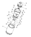
以下、実施の形態を図1乃至図24に基づいて詳細に説明する。まず、第1の実施形態に係るディスクブレーキ1aを図1乃至図9に基づいて説明する。図1に第1の実施形態に係るディスクブレーキ1aを示す。   Hereinafter, embodiments will be described in detail with reference to FIGS. First, the disc brake 1a according to the first embodiment will be described with reference to FIGS. FIG. 1 shows a disc brake 1a according to the first embodiment.

図1及び図3に示すように、第1の実施形態に係るディスクブレーキ1aには、車両の回転部に取り付けられたディスクロータDを挟んで軸方向両側に配置された一対のインナブレーキパッド2及びアウタブレーキパッド3と、キャリパ4とが設けられている。本ディスクブレーキ1は、キャリパ浮動型として構成されている。なお、一対のインナブレーキパッド2及びアウタブレーキパッド3と、キャリパ4とは、車両のナックル等の非回転部に固定されたキャリア5にディスクロータDの軸方向へ移動可能に支持されている。   As shown in FIGS. 1 and 3, the disc brake 1a according to the first embodiment includes a pair of inner brake pads 2 arranged on both sides in the axial direction with a disc rotor D attached to a rotating portion of a vehicle interposed therebetween. The outer brake pad 3 and the caliper 4 are provided. The disc brake 1 is configured as a caliper floating type. The pair of inner brake pad 2, outer brake pad 3, and caliper 4 are supported by a carrier 5 fixed to a non-rotating part such as a knuckle of a vehicle so as to be movable in the axial direction of the disk rotor D.

キャリパ4の主体であるキャリパ本体6は、車両内側のインナブレーキパッド2に対向する基端側に配置されるシリンダ部7と、車両外側のアウタブレーキパッド3に対向する先端側に配置される爪部8とを有している。シリンダ部7には、インナブレーキパッド2側が開口部7Aとなり、その反対側が孔部9Aを有する底壁9により閉じられた有底のシリンダ10が形成されている。このシリンダ10は、開口部7A側の内周部にピストンシール11が介装されている。   The caliper body 6 that is the main body of the caliper 4 includes a cylinder portion 7 that is disposed on the base end side facing the inner brake pad 2 on the vehicle inner side, and a claw that is disposed on the distal end side facing the outer brake pad 3 on the vehicle outer side. Part 8. The cylinder portion 7 is formed with a bottomed cylinder 10 that is closed by a bottom wall 9 having an opening 7A on the inner brake pad 2 side and a hole portion 9A on the opposite side. The cylinder 10 is provided with a piston seal 11 on the inner peripheral portion on the opening 7A side.

ピストン12は、底部12Aと円筒部12Bとなる有底のカップ状に形成される。該ピストン12は、その底部12Aがインナブレーキパッド2に対向するようにシリンダ10内に収められている。ピストン12は、ピストンシール11に接触した状態で軸方向に移動可能にシリンダ10に内装されている。このピストン12とシリンダ10の底壁9との間は、液圧室13としてピストンシール11により画成されている。この液圧室13には、シリンダ部7に設けた図示しないポートを通じて、マスタシリンダや液圧制御ユニットなどの図示しない液圧源から液圧が供給されるようになっている。ピストン12は、インナブレーキパッド2に対向する底面にの外周側に凹部14が設けられている。この凹部14は、インナブレーキパッド2の背面に形成されている凸部15が係合しており、この係合によってピストン12がシリンダ10、ひいてはキャリパ本体6に対して回り止めされている。また、ピストン12の底部12Aとシリンダ10との間には、シリンダ10内への異物の進入を防ぐダストブーツ16が介装されている。   The piston 12 is formed in a bottomed cup shape that forms a bottom portion 12A and a cylindrical portion 12B. The piston 12 is housed in the cylinder 10 such that its bottom 12A faces the inner brake pad 2. The piston 12 is housed in the cylinder 10 so as to be movable in the axial direction while being in contact with the piston seal 11. A space between the piston 12 and the bottom wall 9 of the cylinder 10 is defined by a piston seal 11 as a hydraulic chamber 13. The fluid pressure chamber 13 is supplied with fluid pressure from a fluid pressure source (not shown) such as a master cylinder or a fluid pressure control unit through a port (not shown) provided in the cylinder portion 7. The piston 12 is provided with a recess 14 on the outer peripheral side on the bottom surface facing the inner brake pad 2. The concave portion 14 is engaged with a convex portion 15 formed on the back surface of the inner brake pad 2, and the piston 12 is prevented from rotating with respect to the cylinder 10 and eventually the caliper body 6 by this engagement. Further, a dust boot 16 is interposed between the bottom 12 </ b> A of the piston 12 and the cylinder 10 to prevent foreign matter from entering the cylinder 10.

キャリパ本体6のシリンダ10の底壁9側には気密的にハウジング35が取り付けられている。該ハウジング35の一端開口には気密的にカバー39が取り付けられている。なお、ハウジング35とシリンダ10とはシール51によって気密性が保持されている。また、ハウジング35とカバー39とはシール40によって気密性が保持されている。ハウジング35には、キャリパ本体6と並ぶように、電動モータの一例であるモータ38がシール50を介して密閉的に取り付けられている。なお、本実施形態では、モータ38をハウジング35の外側に配置したが、モータ38を覆うようにハウジング35を形成し、ハウジング35内にモータ38を収容してもよい。この場合、シール50が不要となり、組み付け工数の低減を図ることが可能となる。   A housing 35 is airtightly attached to the bottom wall 9 side of the cylinder 10 of the caliper body 6. A cover 39 is attached to one end opening of the housing 35 in an airtight manner. The housing 35 and the cylinder 10 are kept airtight by a seal 51. The housing 35 and the cover 39 are kept airtight by a seal 40. A motor 38, which is an example of an electric motor, is hermetically attached to the housing 35 via a seal 50 so as to be aligned with the caliper body 6. In the present embodiment, the motor 38 is disposed outside the housing 35, but the housing 35 may be formed so as to cover the motor 38 and the motor 38 may be accommodated in the housing 35. In this case, the seal 50 becomes unnecessary, and it is possible to reduce the number of assembly steps.

キャリパ本体6には、ピストン12を推進して制動位置に保持させるパーキングブレーキ機構であるピストン保持機構34と、モータ38による回転を増力する減速機構としての平歯多段減速機構37及び遊星歯車減速機構36とが備えられている。上記平歯多段減速機構37及び遊星歯車減速機構36は、ハウジング35内に収納されている。
ピストン保持機構34は、平歯多段減速機構37及び遊星歯車減速機構36からの回転運動、すなわちモータ38の回転を直線方向の運動(以下、便宜上直動という。)に変換し、ピストン12に推力を付与してピストン12を移動させるボールアンドランプ機構28と、該ボールアンドランプ機構28の作動によりピストン12を押圧する押圧部材の一部となるプッシュロッド53と、シリンダ10の底壁9とプッシュロッド53との間、言い換えれば、ボールアンドランプ機構28とピストン12との間に配置され、ピストン12を制動位置で保持する推力保持機構としてのねじ機構52とが備えられる。上記ボールアンドランプ機構28及びねじ機構52は、キャリパ本体6のシリンダ10内に収納されている。なお、本実施形態においては、ピストン12を推進する回転力を得るために、モータ38による回転を増力する減速機構としての平歯多段減速機構37及び遊星歯車減速機構36を設けているが、これらは必ずしも設ける必要はない。すなわち、モータ38がピストン12を推進するための回転力を出力できるものであれば、いずれか一方、または両方の減速機構は省略することが可能となっている。
The caliper body 6 includes a piston holding mechanism 34 that is a parking brake mechanism that propels the piston 12 to hold it in the braking position, a flat-tooth multistage reduction mechanism 37 that serves as a reduction mechanism that increases the rotation by the motor 38, and a planetary gear reduction mechanism. 36. The spur multi-stage reduction mechanism 37 and the planetary gear reduction mechanism 36 are housed in a housing 35.
The piston holding mechanism 34 converts the rotational movement from the spur multi-stage reduction mechanism 37 and the planetary gear reduction mechanism 36, that is, rotation of the motor 38 into linear movement (hereinafter referred to as linear movement for convenience), and thrusts the piston 12. And a ball-and-ramp mechanism 28 that moves the piston 12, a push rod 53 that is part of a pressing member that presses the piston 12 by the operation of the ball-and-ramp mechanism 28, and the bottom wall 9 of the cylinder 10 and the push Between the rod 53, in other words, between the ball and ramp mechanism 28 and the piston 12, there is provided a screw mechanism 52 as a thrust holding mechanism for holding the piston 12 in the braking position. The ball and ramp mechanism 28 and the screw mechanism 52 are accommodated in the cylinder 10 of the caliper body 6. In this embodiment, in order to obtain the rotational force for propelling the piston 12, a spur multi-stage reduction mechanism 37 and a planetary gear reduction mechanism 36 are provided as a reduction mechanism that increases the rotation by the motor 38. Is not necessarily provided. That is, as long as the motor 38 can output the rotational force for propelling the piston 12, one or both of the reduction mechanisms can be omitted.

平歯多段減速機構37は、ピニオンギヤ42と、第1減速歯車43と、第2減速歯車44とを有している。ピニオンギヤ42は、筒状に形成され、モータ38の回転軸38Aに圧入固定される孔部42Aと、外周に形成される歯車42Bとを有している。第1減速歯車43は、ピニオンギヤ42の歯車42Bに噛合する大径の大歯車43Aと、大歯車43Aから軸方向に延出して形成される小径の小歯車43Bとが一体的に形成されている。この第1減速歯車43は、一端がハウジング35に支持されると共に他端がカバー39に支持されたシャフト62により回転可能に支持される。第2減速歯車44は、第1減速歯車43の小歯車43Bに噛合する大径の大歯車44Aと、大歯車44Aから軸方向に延出して形成される小径のサンギヤ44Bとが一体形成されている。サンギヤ44Bは後述する遊星歯車減速機構36の一部を構成している。この第2減速歯車44は、カバー39に支持されたシャフト63により回転可能に支持される。   The spur multi-stage reduction mechanism 37 includes a pinion gear 42, a first reduction gear 43, and a second reduction gear 44. The pinion gear 42 is formed in a cylindrical shape, and has a hole 42A that is press-fitted and fixed to the rotary shaft 38A of the motor 38, and a gear 42B that is formed on the outer periphery. The first reduction gear 43 is integrally formed with a large-diameter large gear 43A that meshes with the gear 42B of the pinion gear 42 and a small-diameter small gear 43B that extends from the large gear 43A in the axial direction. . The first reduction gear 43 is rotatably supported by a shaft 62 having one end supported by the housing 35 and the other end supported by the cover 39. The second reduction gear 44 is integrally formed with a large-diameter large gear 44A that meshes with the small gear 43B of the first reduction gear 43 and a small-diameter sun gear 44B that extends from the large gear 44A in the axial direction. Yes. The sun gear 44B constitutes a part of a planetary gear reduction mechanism 36 described later. The second reduction gear 44 is rotatably supported by a shaft 63 supported by the cover 39.

遊星歯車減速機構36は、サンギヤ44Bと、複数個(本実施の形態では3個)のプラネタリギヤ45と、インターナルギヤ46と、キャリア48とを有する。プラネタリギヤ45は、第2減速歯車44のサンギヤ44Bに噛合される歯車45Aと、キャリア48から立設されるピン47を挿通する孔部45Bとを有している。3個のプラネタリギヤ45は、キャリア48の円周上に等間隔に配置される。   The planetary gear speed reduction mechanism 36 includes a sun gear 44B, a plurality (three in this embodiment) of planetary gears 45, an internal gear 46, and a carrier 48. The planetary gear 45 has a gear 45 </ b> A that meshes with the sun gear 44 </ b> B of the second reduction gear 44, and a hole 45 </ b> B through which a pin 47 erected from the carrier 48 is inserted. The three planetary gears 45 are arranged at equal intervals on the circumference of the carrier 48.

キャリア48は、円板状に形成され、その中心に多角形柱48Aがインナパッド2側に突設される。該キャリア48の多角形柱48Aは、後述するボールアンドランプ機構28の回転ランプ29の円柱部29Bに設けた多角形孔29Cと嵌合することで、キャリア48と回転ランプ29とで互いに回転トルクを伝達できるようになっている。キャリア48の外周側には複数のピン用孔48Bが形成されている。該各ピン用孔48Bに、各プラネタリギヤ45を回転可能に支持するピン47が圧入固定されている。該キャリア48及び各プラネタリギヤ45は、ハウジング35の壁面35Aと、インターナルギヤ46の第2減速歯車44側に一体的に設けた環状壁部46Bとにより軸方向の移動が規制されている。また、キャリア48には、その中心に挿通孔48Cが形成される。該挿通孔48Cには、カバー39に支持され、第2減速歯車44を回転自在に支持するシャフト63が圧入固定されている。なお、本実施形態では、キャリア48に設けた多角形柱48Aにより相対的な回転を規制しているが、スプラインやキー等回転トルクを伝達できる機械要素を採用してもよい。   The carrier 48 is formed in a disc shape, and a polygonal column 48 </ b> A projects from the inner pad 2 side at the center thereof. The polygonal column 48A of the carrier 48 is engaged with a polygonal hole 29C provided in a cylindrical portion 29B of the rotating ramp 29 of the ball and ramp mechanism 28 described later, so that the carrier 48 and the rotating ramp 29 rotate with each other. Can be transmitted. A plurality of pin holes 48 </ b> B are formed on the outer peripheral side of the carrier 48. A pin 47 for rotatably supporting each planetary gear 45 is press-fitted and fixed in each pin hole 48B. The carrier 48 and each planetary gear 45 are restricted from moving in the axial direction by a wall surface 35A of the housing 35 and an annular wall portion 46B integrally provided on the second reduction gear 44 side of the internal gear 46. The carrier 48 is formed with an insertion hole 48C at the center thereof. A shaft 63 supported by the cover 39 and rotatably supporting the second reduction gear 44 is press-fitted and fixed in the insertion hole 48C. In the present embodiment, the relative rotation is restricted by the polygonal column 48A provided on the carrier 48, but a mechanical element capable of transmitting rotational torque such as a spline or a key may be employed.

インターナルギヤ46は、各プラネタリギヤ45の歯車45Aがそれぞれ噛合する内歯46Aと、この内歯46Aから連続して第2減速歯車44側に一体的に設けられてプラネタリギヤ45の軸方向の移動を規制する環状壁部46Bとから形成されている。該インターナルギヤ46は、ハウジング35内に圧入固定されるようになっている。   The internal gear 46 is integrally provided on the second reduction gear 44 side continuously with the internal teeth 46A meshed with the gears 45A of the planetary gears 45, and the planetary gears 45 move in the axial direction. An annular wall portion 46B to be regulated is formed. The internal gear 46 is press-fitted and fixed in the housing 35.

ねじ機構52は、ピストン12を制動位置で保持する推力保持機構として構成され、後述する回転直動ランプ31の円筒部31Bの外周(第1ねじ部)に螺合する、スクリュ部材としてのベースナット33と、プッシュロッド53に螺合する、当接部材としてのナット55とを備えている。   The screw mechanism 52 is configured as a thrust holding mechanism that holds the piston 12 in the braking position, and is a base nut as a screw member that is screwed into an outer periphery (first screw portion) of a cylindrical portion 31B of the rotary linear motion ramp 31 described later. 33 and a nut 55 as a contact member that is screwed into the push rod 53.

プッシュロッド53は、ツバ部53Aと螺合部53Cとが一体的に形成されて構成される。該ツバ部53Aは、スラストベアリング56を介して、ボールアンドランプ機構28の回転直動ランプ31に軸方向に対向配置される。ツバ部53Aと後述するリテーナ26との間には、コイルばね27が介装されている。コイルばね27は、プッシュロッド53を常時スラストベアリング56側、すなわち、シリンダ部7の底壁9側へ付勢している。また、コイルばね27は、プッシュロッド53を介して後述のボールアンドランプ機構28の回転直動ランプ31をシリンダ部7の定壁9側へ付勢している。なお、プッシュロッド53には、そのツバ部53Aの外周面に周方向に沿って凸部53Bが複数設けられている。凸部53Bは、後述するリテーナ26の縮径部26Bに、周方向に沿って複数設けられる縦長溝部26Eにそれぞれ嵌合するようになっている。この凸部53Bと縦長溝部26Eとの嵌合により、プッシュロッド53は、縦長溝部26Eの軸方向長さの範囲で軸方向に移動可能であるが、リテーナ26に対して回転方向への移動が規制されている。   The push rod 53 is configured by integrally forming a flange portion 53A and a screwing portion 53C. The flange portion 53 </ b> A is disposed so as to face the rotary linear motion ramp 31 of the ball and ramp mechanism 28 in the axial direction via a thrust bearing 56. A coil spring 27 is interposed between the flange portion 53A and a retainer 26 described later. The coil spring 27 constantly urges the push rod 53 toward the thrust bearing 56 side, that is, the bottom wall 9 side of the cylinder portion 7. Further, the coil spring 27 urges a rotary linear motion lamp 31 of a ball and ramp mechanism 28 (described later) to the constant wall 9 side of the cylinder portion 7 via a push rod 53. The push rod 53 is provided with a plurality of convex portions 53B along the circumferential direction on the outer peripheral surface of the flange portion 53A. The convex portions 53B are adapted to fit into a plurality of vertically long groove portions 26E provided in the circumferential direction in a reduced diameter portion 26B of the retainer 26 described later. The push rod 53 can move in the axial direction within the range of the axial length of the longitudinal groove portion 26E by fitting the convex portion 53B and the longitudinal groove portion 26E, but the push rod 53 can move in the rotational direction with respect to the retainer 26. It is regulated.

ナット55は、貫通孔である孔部55Aを有して一端側に円筒部55Bと他端側にフランジ部54とが一体的に形成されて、軸方向断面でT字状、外観視でキノコ状に構成される。孔部55Aのうち円筒部55Bに該当する位置には、プッシュロッド53の螺合部53C(第3ねじ部)と螺合する、当接部材ねじ部としての螺合部55Cが形成されている。   The nut 55 has a hole portion 55A that is a through-hole, and a cylindrical portion 55B and a flange portion 54 are integrally formed on one end side and a flange portion 54 on the other end side. Configured. At a position corresponding to the cylindrical portion 55B in the hole portion 55A, a screwing portion 55C as a contact member screw portion that is screwed with a screwing portion 53C (third screw portion) of the push rod 53 is formed. .

フランジ部54の外周端には、凸部54Aが周方向に間隔を置いて複数形成される。これら各凸部54Aは、ピストン12の円筒部12Bの内周面に軸方向に延び周方向に間隔を置いて複数形成された平面部12Cに当接するようになっている。この当接により、ナット55は、ピストン12に対して軸方向には移動可能であるが、回転方向への移動が規制されている。ナット55のフランジ部54の先端面には、傾斜面54Bが形成されている。該傾斜面54Bは、ピストン12の底部12Aの内側に形成された傾斜面12Dと当接可能になっている。ナット55のフランジ部54の傾斜面54Bがピストン12の傾斜面12Dに当接することで、モータ38からの回転力が、ねじ機構52であるプッシュロッド53、ナット55及びフランジ部54を介してピストン12に伝達されるようになっている。これにより、ピストン12が前進するようになっている。なお、ナット55のフランジ部54の凸部54A及び傾斜面54Bには溝部54C(図3参照)、54Dが複数形成されている。これら溝部54C、54Dは、ピストン12の底部12Aとフランジ部54とにより囲まれた空間を液圧室13に連通させ、ブレーキ液の流通を可能として、上記空間のエア抜き性を確保するようにしている。   A plurality of convex portions 54 </ b> A are formed on the outer peripheral end of the flange portion 54 at intervals in the circumferential direction. Each of these convex portions 54A extends in the axial direction on the inner peripheral surface of the cylindrical portion 12B of the piston 12 and comes into contact with a plurality of planar portions 12C formed at intervals in the circumferential direction. By this contact, the nut 55 can move in the axial direction with respect to the piston 12, but movement in the rotational direction is restricted. An inclined surface 54 </ b> B is formed on the front end surface of the flange portion 54 of the nut 55. The inclined surface 54B can come into contact with an inclined surface 12D formed inside the bottom 12A of the piston 12. When the inclined surface 54B of the flange portion 54 of the nut 55 contacts the inclined surface 12D of the piston 12, the rotational force from the motor 38 is changed to the piston via the push rod 53, the nut 55, and the flange portion 54 that are the screw mechanism 52. 12 is transmitted. As a result, the piston 12 moves forward. A plurality of grooves 54C (see FIG. 3) and 54D are formed in the convex portion 54A and the inclined surface 54B of the flange portion 54 of the nut 55. These groove portions 54C and 54D communicate the space surrounded by the bottom portion 12A of the piston 12 and the flange portion 54 with the hydraulic pressure chamber 13 so that the brake fluid can be circulated to ensure the air bleeding performance of the space. ing.

プッシュロッド53とナット55との螺合部53C,55Cは、ピストン12からの回転直動ランプ31への軸方向荷重によってはナット55が回転しないように、その逆効率が0以下になるように、すなわち、不可逆性が大きなねじに設定されている。本実施形態においては、プッシュロッド53と当接部材であるナット55とから押圧部材が構成されている。   The screwing portions 53C and 55C of the push rod 53 and the nut 55 have a reverse efficiency of 0 or less so that the nut 55 does not rotate due to an axial load from the piston 12 to the rotary linear motion ramp 31. That is, the irreversibility is set to a large screw. In the present embodiment, a push member is composed of the push rod 53 and the nut 55 which is a contact member.

ボールアンドランプ機構28は、入力部材としての回転ランプ29と、従動部材としての回転直動ランプ31と、回転ランプ29と回転直動ランプ31との間に介装されるボール32とを備えている。本実施形態において、回転直動ランプ31は、スクリュ部材としてのベースナット33と上述したねじ機構29としての機能も有している。   The ball-and-ramp mechanism 28 includes a rotation ramp 29 as an input member, a rotation / linear motion ramp 31 as a driven member, and a ball 32 interposed between the rotation ramp 29 and the rotation / linear motion ramp 31. Yes. In the present embodiment, the rotation / linear motion ramp 31 also has a function as a base nut 33 as a screw member and the screw mechanism 29 described above.

回転ランプ29は、円板状の回転プレート29Aと、該回転プレート29Aの略中心から一体的に延びる円柱部29Bとからなり、軸方向断面T字状に形成される。該円柱部29Bは、ベースナット33の底壁33Aに設けた挿通孔33D及びシリンダ10の底壁9に設けた孔部9Aに挿通されている。該円柱部29Bの先端には、キャリア48に設けた多角形柱48Aが嵌合する多角形孔29Cが形成されている。また、回転プレート29Aの円柱部29B側と反対側の面には、周方向に沿って所定の傾斜角を有して円弧状に延びるとともに径方向において円弧状断面を有する複数、本実施形態においては3つのボール溝29Dが形成されている。また、回転プレート29Aは、ベースナット33の底壁33Aに対して、スラストベアリング30を介して回転自在に支持されている。シリンダ10の底壁9の孔部9Aと回転ランプ29の円柱部29Bの外周面との間にはシール61が設けられ、液圧室13の液密性が保持されている。なお、回転ランプ29の円柱部29Bの先端部には止め輪64が装着されており、回転ランプ29のキャリパ本体6に対するインナ及びアウタブレーキパッド2、3側への移動、すなわち、ロータ軸方向への移動が規制されている。そして、上記のような回転ランプ29の規制によって、ベースナット33は、キャリパ本体6に対してロータ軸方向に移動しないようになっている。したがって、ベースナット33に形成された雌ねじ部33Cもキャリパ本体6に対してロータ軸方向に移動しないようになっている。   The rotation lamp 29 includes a disk-shaped rotation plate 29A and a columnar portion 29B extending integrally from substantially the center of the rotation plate 29A, and is formed in an axial cross section T shape. The cylindrical portion 29 </ b> B is inserted through an insertion hole 33 </ b> D provided in the bottom wall 33 </ b> A of the base nut 33 and a hole portion 9 </ b> A provided in the bottom wall 9 of the cylinder 10. A polygonal hole 29C into which a polygonal column 48A provided on the carrier 48 is fitted is formed at the tip of the cylindrical portion 29B. Further, in the present embodiment, the surface of the rotating plate 29A opposite to the cylindrical portion 29B side has a predetermined inclination angle along the circumferential direction and extends in an arc shape and has an arc-shaped cross section in the radial direction. Are formed with three ball grooves 29D. The rotating plate 29 </ b> A is rotatably supported by the bottom wall 33 </ b> A of the base nut 33 via a thrust bearing 30. A seal 61 is provided between the hole 9 </ b> A of the bottom wall 9 of the cylinder 10 and the outer peripheral surface of the cylindrical portion 29 </ b> B of the rotating lamp 29, and the liquid tightness of the hydraulic chamber 13 is maintained. A retaining ring 64 is attached to the tip of the cylindrical portion 29B of the rotating ramp 29, and the rotating ramp 29 moves toward the inner and outer brake pads 2, 3 with respect to the caliper body 6, that is, in the rotor axial direction. Movement is regulated. The base nut 33 is prevented from moving in the rotor axial direction with respect to the caliper body 6 due to the restriction of the rotating lamp 29 as described above. Accordingly, the internal thread portion 33 </ b> C formed on the base nut 33 is also prevented from moving in the rotor axial direction with respect to the caliper body 6.

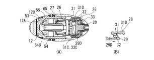
回転直動ランプ31は、図2にも示されるように、円板状の回転直動プレート31Aと、該回転直動プレート31Aの外周端から立設される円筒部31Bとからなる有底円筒状に形成されている。回転直動プレート31Aの、回転ランプ29の回転プレート29Aとの対向面には、周方向に沿って所定の傾斜角を有して円弧状に延びるとともに径方向において円弧状断面を有する複数、本実施形態においては3つのボール溝31Dが形成されている。また、円筒部31Bの外周面には、ベースナット33の円筒部33Bの内周面に設けた雌ねじ部33C(第2ねじ部)と螺合する、第1ねじ部としての雄ねじ部31Cが形成されている。   As shown in FIG. 2, the rotary linear motion lamp 31 is a bottomed cylinder composed of a disc-shaped rotational linear motion plate 31A and a cylindrical portion 31B standing from the outer peripheral end of the rotational linear motion plate 31A. It is formed in a shape. On the surface of the rotary linear motion plate 31A that faces the rotary plate 29A of the rotary lamp 29, a plurality of books that extend in an arc shape with a predetermined inclination angle along the circumferential direction and have an arc-shaped cross section in the radial direction In the embodiment, three ball grooves 31D are formed. Further, on the outer peripheral surface of the cylindrical portion 31B, a male screw portion 31C as a first screw portion is formed which is screwed with a female screw portion 33C (second screw portion) provided on the inner peripheral surface of the cylindrical portion 33B of the base nut 33. Has been.

ベースナット33は、底壁33Aと、該底壁33Aの外周端から立設される円筒部33Bとからなる有底筒状に形成されている。該円筒部33Bの内周面には、回転直動ランプ31の円筒部31Bの外周面に設けた雄ねじ部31C(第1ねじ部)と螺合する、第2ねじ部としての雌ねじ部33Cが形成される。ベースナット33の底壁33Aの略中心には回転ランプ29の円柱部29Bが挿通される挿通孔33Dが形成されている。そして、ベースナット33は、その円筒部33B内に回転直動ランプ31及び回転ランプ29の回転プレート29Aを収容するようにして、その底壁33Aの挿通孔33Dに回転ランプ29の円柱部29Bが挿通されている。また、ベースナット33は、底壁33Aがシリンダ10の底壁9と回転ランプ29の回転プレート29Aとの間に配置されたスラストベアリング30とスラストベアリング58との間に挟持されている。これにより、ベースナット33は、スラストベアリング58及びスラストワッシャ57を介して、シリンダ10の底壁9に対して回転可能に支持されるようになっている。しかしながら、ベースナット33は、その外周に設けた複数の凸部33E(図3参照)がリテーナ26に設けた凹部26G(図3参照)と嵌合することでリテーナ26に対する相対的な回転移動が規制されている。また、リテーナ26の大径部26Aの後端部には、複数のツメ部26F(図3参照)が形成されており、該リテーナ26内の所定位置にベースナット33を組み付けた後、各ツメ部26Fをリテーナ26の中心方向へ折り込むことで、ベースナット33の第2減速歯車44側への移動が規制されるようになっている。   The base nut 33 is formed in a bottomed cylindrical shape including a bottom wall 33A and a cylindrical portion 33B erected from the outer peripheral end of the bottom wall 33A. On the inner peripheral surface of the cylindrical portion 33B, there is a female screw portion 33C as a second screw portion that is screwed with a male screw portion 31C (first screw portion) provided on the outer peripheral surface of the cylindrical portion 31B of the rotary linear motion lamp 31. It is formed. An insertion hole 33D through which the cylindrical portion 29B of the rotating lamp 29 is inserted is formed at the approximate center of the bottom wall 33A of the base nut 33. The base nut 33 accommodates the rotary translation lamp 31 and the rotary plate 29A of the rotary lamp 29 in the cylindrical portion 33B, and the cylindrical portion 29B of the rotary lamp 29 is inserted into the insertion hole 33D of the bottom wall 33A. It is inserted. The base nut 33 is sandwiched between a thrust bearing 30 and a thrust bearing 58 having a bottom wall 33A disposed between the bottom wall 9 of the cylinder 10 and the rotating plate 29A of the rotating ramp 29. Thereby, the base nut 33 is rotatably supported with respect to the bottom wall 9 of the cylinder 10 via the thrust bearing 58 and the thrust washer 57. However, the base nut 33 has a plurality of convex portions 33E (see FIG. 3) provided on the outer periphery thereof and engages with concave portions 26G (see FIG. 3) provided in the retainer 26, so that the relative rotation movement with respect to the retainer 26 is achieved. It is regulated. A plurality of claw portions 26F (see FIG. 3) are formed at the rear end portion of the large-diameter portion 26A of the retainer 26. After the base nut 33 is assembled at a predetermined position in the retainer 26, each claw By folding the portion 26F toward the center of the retainer 26, the movement of the base nut 33 toward the second reduction gear 44 is restricted.

なお、回転直動ランプ31の円筒部31Bの雄ねじ部31C及びベースナット33の円筒部33Bに設けた雌ねじ部33Cは、回転ランプ29を一方向に回転させて、回転ランプ29及び回転直動ランプ31の対向するボール溝29D、31D間のボール32の転動作用により回転直動ランプ31が回転ランプ29から離間する場合、回転直動ランプ31が回転ランプ29と同方向に回転したときに、回転直動ランプ31がベースナット33から離間するように形成されている。   The external thread portion 31C of the cylindrical portion 31B of the rotary linear motion lamp 31 and the internal thread portion 33C provided on the cylindrical portion 33B of the base nut 33 rotate the rotational ramp 29 in one direction, thereby rotating the rotational ramp 29 and the rotational linear motion ramp. When the rotation / linear motion ramp 31 is separated from the rotation ramp 29 due to the rolling motion of the ball 32 between the opposing ball grooves 29D and 31D, when the rotation / linear motion ramp 31 rotates in the same direction as the rotation ramp 29, The rotary linear motion lamp 31 is formed so as to be separated from the base nut 33.

ボール32は、転動部材としての鋼球からなり、本実施形態においては3つ設けられている。ボール32は、回転ランプ29の回転プレート29Aの各ボール溝29Dと、回転直動ランプ31の回転直動プレート31Aの各ボール溝31Dとの間にそれぞれ1つずつ介装されている。そして、回転ランプ29に回転トルクを加えると、ボール溝29Dと31Dの間をボール32が転動するようになっている。ここで、ボール32が転動すると、回転直動ランプ31は、ベースナット33と螺合しているため、ベースナット33がシリンダ10に対して回転していないときには、ベースナット33に対して回転しながら軸方向に推進するようになっている。このとき、回転直動ランプ31は、ボール32の転動により発生する回転直動ランプ31の回転トルクと、回転直動ランプ31とベースナット33との螺合部である雄ねじ部31C及び雌ねじ部33Cの回転抵抗トルクとが釣り合うまで、軸方向に推進されるようになっている。また、回転直動ランプ31とベースナット33との螺合部分である雄ねじ部31C及び雌ねじ部33Cは、ピストン12からの回転直動ランプ31への軸方向荷重によってはベースナット33が回転しない、すなわち、雄ねじ部31C及び雌ねじ部33Cの逆効率が0以下になるように、言い換えれば、不可逆性が大きなねじに設定されている。なお、ボール溝29D、31Dは、周方向に沿った傾斜の途中に窪みを付けたり、傾斜を途中で変化させて構成するようにしても良い。   The balls 32 are made of steel balls as rolling members, and three balls 32 are provided in this embodiment. One ball 32 is interposed between each ball groove 29 </ b> D of the rotation plate 29 </ b> A of the rotation ramp 29 and each ball groove 31 </ b> D of the rotation translation plate 31 </ b> A of the rotation translation lamp 31. When a rotational torque is applied to the rotation lamp 29, the ball 32 rolls between the ball grooves 29D and 31D. Here, when the ball 32 rolls, the rotation linearly acting ramp 31 is screwed with the base nut 33, so that when the base nut 33 is not rotating with respect to the cylinder 10, it rotates with respect to the base nut 33. While propelled in the axial direction. At this time, the rotation / linear motion ramp 31 includes a rotational torque of the rotation / linear motion ramp 31 generated by rolling of the ball 32, and a male screw portion 31C and a female thread portion which are screwed portions of the rotation / linear motion ramp 31 and the base nut 33. It is propelled in the axial direction until the rotational resistance torque of 33C is balanced. Further, the male screw portion 31C and the female screw portion 33C, which are screwed portions of the rotary linear motion lamp 31 and the base nut 33, do not rotate the base nut 33 due to the axial load from the piston 12 to the rotary linear motion ramp 31. That is, the irreversibility is set to a large screw so that the reverse efficiency of the male screw portion 31C and the female screw portion 33C is 0 or less. The ball grooves 29 </ b> D and 31 </ b> D may be configured by forming a recess in the middle of the inclination along the circumferential direction or changing the inclination in the middle.

リテーナ26は、全体が略筒形状で構成され、シリンダ10の底壁9側に位置する大径部26Aと、この大径部26Aからシリンダ10の開口7A方向に向けて縮径する縮径部26Bと、この縮径部26Bからシリンダ10の開口7A方向に向けて延出する小径部26Cとから構成されている。大径部26Aの先端部(図1中右側)には、中心側に部分的に折り込まれてベースナット33を係止する複数のツメ部26F(図3参照)が形成されている。また、リテーナ26の縮径部26Bには、周方向に沿って複数設けた縦長溝部26Eが形成され、プッシュロッド53のツバ部53Aに設けた複数の対応する凸部53Bが嵌合されている。この嵌合によって、プッシュロッド53は、リテーナ26に対して回り止めされるとともに、縦長溝部26Eをリテーナ26に対して軸方向に移動可能となっている。   The retainer 26 has a substantially cylindrical shape as a whole, and has a large-diameter portion 26A located on the bottom wall 9 side of the cylinder 10 and a reduced-diameter portion that decreases in diameter from the large-diameter portion 26A toward the opening 7A of the cylinder 10. 26B and a small diameter portion 26C extending from the reduced diameter portion 26B toward the opening 7A of the cylinder 10. A plurality of claw portions 26 </ b> F (see FIG. 3) that are partially folded toward the center side to lock the base nut 33 are formed at the distal end portion (right side in FIG. 1) of the large diameter portion 26 </ b> A. Further, a plurality of vertically long grooves 26E provided along the circumferential direction are formed on the reduced diameter portion 26B of the retainer 26, and a plurality of corresponding convex portions 53B provided on the flange portion 53A of the push rod 53 are fitted. . By this fitting, the push rod 53 is prevented from rotating with respect to the retainer 26, and the vertically long groove portion 26 </ b> E can be moved in the axial direction with respect to the retainer 26.

また、リテーナ26の小径部26Cの外周には、一方向クラッチ部材としてのスプリングクラッチ65のコイル部65Aが巻き付けられている。このスプリングクラッチ65は、リテーナ26が一方向へ回転するときには回転トルクを付与するが、他方向へ回転するときに回転トルクを殆ど付与しないようになっている。ここでは、ナット55がボールアンドランプ機構28の方向へ移動するときの回転方向に対して回転抵抗トルクを付与するようにしている。なお、スプリングクラッチ65の回転抵抗トルクの大きさは、回転直動ランプ31とベースナット33とが軸方向で互いに近接する際、コイルばね27の付勢力によって発生する回転直動ランプ31とベースナット33との螺合部31C、33Cの回転抵抗トルクよりも大きいものとなっている。また、スプリングクラッチ65の先端側(図1中左側)には、リング部65Bが形成されており、ナット55の各凸部54Aと同様に、ピストン12の平面部12Cと当接している。これにより、スプリングクラッチ65は、ピストン12に対して軸方向の移動は可能であるが、回転方向への移動が規制されるようになっている。本実施形態においては、回転直動ランプ31の雄ねじ部31C、ベースナット33、リテーナ26、プッシュロッド53、及びナット55によって、ねじ機構が構成されている。   A coil portion 65A of a spring clutch 65 as a one-way clutch member is wound around the outer periphery of the small diameter portion 26C of the retainer 26. The spring clutch 65 applies rotational torque when the retainer 26 rotates in one direction, but hardly applies rotational torque when the retainer 26 rotates in the other direction. Here, a rotational resistance torque is applied to the rotational direction when the nut 55 moves in the direction of the ball and ramp mechanism 28. Note that the magnitude of the rotational resistance torque of the spring clutch 65 is such that the rotational linear motion ramp 31 and the base nut generated by the biasing force of the coil spring 27 when the rotational linear motion ramp 31 and the base nut 33 are close to each other in the axial direction. This is larger than the rotational resistance torque of the threaded portions 31 </ b> C and 33 </ b> C. Further, a ring portion 65B is formed on the distal end side (left side in FIG. 1) of the spring clutch 65, and is in contact with the flat surface portion 12C of the piston 12 like each convex portion 54A of the nut 55. As a result, the spring clutch 65 can move in the axial direction with respect to the piston 12, but is restricted from moving in the rotational direction. In the present embodiment, the screw mechanism is configured by the male screw portion 31C of the rotary linear motion lamp 31, the base nut 33, the retainer 26, the push rod 53, and the nut 55.

モータ38には、該モータ38を駆動制御する制御手段である電子制御装置からなるECU70が接続されている。ECU70には、駐車ブレーキの作動・解除を指示すべく操作されるパーキングスイッチ71が接続されている。また、ECU70には、図示しない車両側からの信号に基づきパーキングスイッチ71の操作によらずに作動することもできる。   The motor 38 is connected to an ECU 70 that is an electronic control unit that is a control means for driving and controlling the motor 38. The ECU 70 is connected to a parking switch 71 that is operated to instruct the operation / release of the parking brake. Further, the ECU 70 can be operated regardless of the operation of the parking switch 71 based on a signal from the vehicle side (not shown).

次に、第1の実施形態に係るディスクブレーキ1aの作用を説明する。
まず、ブレーキペダルの操作による通常の液圧ブレーキとしてのディスクブレーキ1aの制動時における作用を説明する。運転者によりブレーキペダルが踏み込まれると、ブレーキペダルの踏力に応じた液圧がマスタシリンダから液圧回路(ともに図示しない)を経てキャリパ4内の液圧室13に供給される。これにより、ピストン12がピストンシール11を弾性変形させながら非制動時の原位置から前進(図1の左方向に移動)してインナブレーキパッド2をディスクロータDに押し付ける。そしてキャリパ本体6は、ピストン12の押圧力の反力によりキャリア5に対して図1における右方向に移動して、爪部8に取り付けられたアウタブレーキパッド3をディスクロータDに押し付ける。この結果、ディスクロータDが一対のインナ及びアウタブレーキパッド2、3により挟みつけられて摩擦力が発生し、ひいては、車両の制動力が発生することになる。
Next, the operation of the disc brake 1a according to the first embodiment will be described.
First, the action at the time of braking of the disc brake 1a as a normal hydraulic brake by the operation of the brake pedal will be described. When the driver depresses the brake pedal, the hydraulic pressure corresponding to the depressing force of the brake pedal is supplied from the master cylinder to the hydraulic chamber 13 in the caliper 4 via a hydraulic circuit (both not shown). Accordingly, the piston 12 moves forward (moves in the left direction in FIG. 1) from the original position during non-braking while pressing the piston seal 11 against the disc rotor D while elastically deforming the piston seal 11. The caliper body 6 moves to the right in FIG. 1 with respect to the carrier 5 by the reaction force of the pressing force of the piston 12, and presses the outer brake pad 3 attached to the claw portion 8 against the disc rotor D. As a result, the disc rotor D is sandwiched between the pair of inner and outer brake pads 2 and 3 to generate a frictional force, and hence a braking force for the vehicle.

そして、運転者がブレーキペダルを解放すると、マスタシリンダからの液圧の供給が途絶えて液圧室13内の液圧が低下する。これにより、ピストン12は、ピストンシール11の弾性変形の復元力によって原位置まで後退して制動力が解除される。ちなみに、インナ及びアウタブレーキパッド2、3の摩耗に伴いピストン12の移動量が増大してピストンシール11の弾性変形の限界を越えると、ピストン12とピストンシール11との間に滑りが生じる。この滑りによってキャリパ本体6に対するピストン12の原位置が移動して、パッドクリアランスが一定に調整されるようになっている。   And when a driver | operator releases a brake pedal, supply of the hydraulic pressure from a master cylinder stops, and the hydraulic pressure in the hydraulic pressure chamber 13 falls. As a result, the piston 12 is retracted to the original position by the restoring force of the elastic deformation of the piston seal 11 and the braking force is released. Incidentally, when the movement amount of the piston 12 increases with the wear of the inner and outer brake pads 2 and 3 and exceeds the limit of the elastic deformation of the piston seal 11, slip occurs between the piston 12 and the piston seal 11. By this slip, the original position of the piston 12 with respect to the caliper body 6 is moved, and the pad clearance is adjusted to be constant.

次に、車両の停止状態を維持するための作用の一例である、駐車ブレーキとしての作用を図4に基づいて図1も参照しながら説明する。図1及び図4は、駐車ブレーキが解除されている状態を示している。この状態からパーキングスイッチ71が操作されて駐車ブレーキを作動させる時には、ECU70によってモータ38が駆動されて、平歯多段減速機構37を介して遊星歯車減速機構36のサンギヤ44Bが回転する。このサンギヤ44Bの回転により、各プラネタリギヤ45を介してキャリア48が回転する。キャリア48の回転力は、回転ランプ29に伝達される。   Next, an operation as a parking brake, which is an example of an operation for maintaining the stopped state of the vehicle, will be described with reference to FIG. 1 and 4 show a state where the parking brake is released. When the parking switch 71 is operated from this state to operate the parking brake, the motor 38 is driven by the ECU 70, and the sun gear 44B of the planetary gear speed reduction mechanism 36 rotates via the spur multi-stage speed reduction mechanism 37. Due to the rotation of the sun gear 44 </ b> B, the carrier 48 is rotated via each planetary gear 45. The rotational force of the carrier 48 is transmitted to the rotation lamp 29.

ここで、ボールアンドランプ機構28の回転直動ランプ31は、プッシュロッド53を介して伝達されるコイルばね27の付勢力のため、キャリパ本体6に対して前進(図1中左方向へ移動)するために、ある一定以上の推力、ひいては回転トルクT1が必要となっている。これに対して、一対のインナ及びアウタブレーキパッド2、3とディスクロータDとが当接しておらず、ピストン12からディスクロータDへの押圧力が発生していない状態では、プッシュロッド53を回転させるための必要回転トルクT2が、回転直動ランプ31を前進させるための必要回転トルクT1よりも十分小さくなっている。また、駐車ブレーキを作動させる時には、スプリングクラッチ65による回転抵抗トルクT3も付与されない。   Here, the linear motion ramp 31 of the ball and ramp mechanism 28 moves forward (moves leftward in FIG. 1) with respect to the caliper body 6 due to the biasing force of the coil spring 27 transmitted through the push rod 53. In order to achieve this, a thrust exceeding a certain level, and hence a rotational torque T1, is required. In contrast, when the pair of inner and outer brake pads 2 and 3 and the disk rotor D are not in contact with each other and no pressing force is generated from the piston 12 to the disk rotor D, the push rod 53 is rotated. The required rotational torque T2 for causing the rotation linear motion ramp 31 to move forward is sufficiently smaller than the necessary rotational torque T1 for causing the rotational linear motion lamp 31 to advance. Further, when the parking brake is operated, the rotational resistance torque T3 by the spring clutch 65 is not applied.

このため、キャリア48から回転ランプ29への回転力の伝達初期においては、回転直動ランプ31が前進しないので、図5に示すように、回転ランプ29と回転直動ランプ31とが共回りし始める。その回転力は、機械損失分を除いた殆どが回転直動ランプ31とベースナット33との螺合部31C、33Cからリテーナ26及びプッシュロッド53を介してねじ機構52に伝達される。したがって、機械効率が良い状態でねじ機構52が作動することになる。すなわち、キャリア48は、その回転力により回転ランプ29、回転直動ランプ31、ベースナット33、リテーナ26及びプッシュロッド53を共に一体となって回転させる。このプッシュロッド53の回転によりナット55が前進(図1中左方向へ移動)して、ナット55のフランジ部54の傾斜面54Bがピストン12の傾斜面12Dに当接して、傾斜面12Dを押圧することでピストン12が前進することになる。   Therefore, at the initial stage of transmission of the rotational force from the carrier 48 to the rotation ramp 29, the rotation / linear motion ramp 31 does not move forward, so that the rotation ramp 29 and the rotation / linear motion ramp 31 rotate together as shown in FIG. start. Most of the rotational force excluding the mechanical loss is transmitted to the screw mechanism 52 through the retainer 26 and the push rod 53 from the screwed portions 31C, 33C between the rotary linear motion lamp 31 and the base nut 33. Therefore, the screw mechanism 52 operates in a state where the mechanical efficiency is good. That is, the carrier 48 rotates the rotation ramp 29, the rotation linear motion ramp 31, the base nut 33, the retainer 26, and the push rod 53 together by the rotational force. As the push rod 53 rotates, the nut 55 moves forward (moves leftward in FIG. 1), and the inclined surface 54B of the flange portion 54 of the nut 55 comes into contact with the inclined surface 12D of the piston 12 to press the inclined surface 12D. By doing so, the piston 12 moves forward.

さらにモータ38が駆動されて、ねじ機構52の作用によりピストン12によるディスクロータDへの押圧力が発生し始めると、今度は、その押圧力に伴う軸力によってプッシュロッド53とナット55との螺合部で発生する回転抵抗が増大して、ナット55を前進させるための必要回転トルクT2が増大していく。そして、必要回転トルクT2は、ボールアンドランプ機構28を作動、すなわち回転直動ランプ31を前進させるための必要回転トルクT1よりも大きくなる。この結果、プッシュロッド53の回転が停止して、プッシュロッド53と相対的な回転が規制されるリテーナ26を介してベースナット33の回転が停止する。すると、図6に示すように、回転直動ランプ31が回転しながら軸方向に前進することで、ねじ機構52、すなわちプッシュロッド53及びナット55を介してピストン12が前進し、ピストン12のディスクロータDへの押圧力が増大する。このとき、回転直動ランプ31には、回転ランプ29からの回転トルクの付与により、ボール溝31Dで発生する推力と、ベースナット33との螺合によって発生する推力の合計が付与される。また、このとき、プッシュロッド53は、コイルばね27の付勢力に抗して前進するようになっている。なお、本実施形態では、最初に、ねじ機構52が作動することによりナット5が前進することでピストン12を前進させてディスクロータDへの押圧力を得るので、ねじ機構52の作動により一対のインナ及びアウタブレーキパッド2、3の経時的な摩耗によって変化するピストン12に対するナット5の原位置を調整することができる。 When the motor 38 is further driven and the screw mechanism 52 causes the piston 12 to start generating a pressing force against the disk rotor D, this time, the axial force associated with the pressing force causes the push rod 53 and the nut 55 to be screwed. The rotational resistance generated at the joint increases, and the necessary rotational torque T2 for moving the nut 55 forward increases. The required rotational torque T2 is larger than the required rotational torque T1 for operating the ball and ramp mechanism 28, that is, for moving the rotary linear motion lamp 31 forward. As a result, the rotation of the push rod 53 stops, and the rotation of the base nut 33 stops via the retainer 26 whose rotation relative to the push rod 53 is restricted. Then, as shown in FIG. 6, the rotary linear motion lamp 31 moves forward in the axial direction while rotating, whereby the piston 12 moves forward via the screw mechanism 52, that is, the push rod 53 and the nut 55, and the disk of the piston 12 is moved forward. The pressing force to the rotor D increases. At this time, the rotational linear motion lamp 31 is given the total of the thrust generated by the ball groove 31 </ b> D and the thrust generated by the screwing with the base nut 33 due to the application of the rotational torque from the rotational lamp 29. At this time, the push rod 53 moves forward against the urging force of the coil spring 27. Pair In the present embodiment, first, since the piston 12 is advanced by a nut 5 5 is advanced by a screw mechanism 52 is operated to obtain a pressing force to the disk rotor D, by the operation of the screw mechanism 52 it is possible to adjust the original position of the nut 5 5 against the inner and the piston 12 that varies over time wear of the outer brake pads 2 and 3.

ここで、ボールアンドランプ機構28のリードL(回転ランプ29が1回転するときの回転直動ランプ31の進み量)は、次の式で表される。
L=Lscrew×LB&R/(Lscrew+LB&R
Here, the lead L of the ball-and-ramp mechanism 28 (advancing amount of the rotation linear motion lamp 31 when the rotation lamp 29 makes one rotation) is expressed by the following equation.
L = L screw × L B & R / (L screw + L B & R )

ただし、Lscrewは、回動直動ランプ31とベースナット33との螺合部31C、33Cのリードで、LB&Rは、各ボール溝29D、31Dでのリードである。例えば、Lscrew=3mm、LB&R=3mmとすると、L=1.5mmとなり、リードを小さくして増力比(回転トルクに対する推力)を上げることができる。 However, L screw is a lead of the screwing portions 31C and 33C between the rotation linear motion lamp 31 and the base nut 33, and L B & R is a lead in each of the ball grooves 29D and 31D. For example, if L screw = 3 mm and L B & R = 3 mm, L = 1.5 mm, and the lead can be reduced to increase the force increase ratio (thrust against rotational torque).

そして、ECU70は、一対のインナ及びアウタブレーキパッド2、3からディスクロータDへの押圧力が所定値に到達するまで、例えば、モータ38の電流値が所定値に達するまでモータ38を駆動する。その後、ECU70は、ディスクロータDへの押圧力が所定値に到達すると、モータ38への通電を停止する。すると、ボールアンドランプ機構28は、回転ランプ29の回転が停止するので、各ボール溝29D、31D間のボール32の転動作用による回転直動ランプ31への推力付与がなくなる。回転直動ランプ31には、ディスクロータDへの押圧力の反力がピストン12及びねじ機構52を介して作用するが、回転直動ランプ31はベースナット33との間で逆作動しない雄ねじ部31C及び雌ねじ部33Cで螺合されているので、回転直動ランプ31は回転せずに停止状態が維持されて、ピストン12が制動位置に保持される。これにより制動力の保持がなされて駐車ブレーキの作動が完了する。   The ECU 70 drives the motor 38 until the pressing force from the pair of inner and outer brake pads 2 and 3 to the disc rotor D reaches a predetermined value, for example, until the current value of the motor 38 reaches a predetermined value. Thereafter, when the pressing force to the disk rotor D reaches a predetermined value, the ECU 70 stops energizing the motor 38. Then, since the rotation of the rotation ramp 29 stops in the ball and ramp mechanism 28, thrust is not applied to the rotation linear motion ramp 31 due to the rolling motion of the ball 32 between the ball grooves 29D and 31D. Although the reaction force of the pressing force to the disk rotor D acts on the rotation linear motion lamp 31 via the piston 12 and the screw mechanism 52, the rotation linear motion ramp 31 does not reversely operate with the base nut 33. Since it is screwed by 31C and the internal thread part 33C, the rotation linear motion lamp 31 is not rotated and the stopped state is maintained, and the piston 12 is held at the braking position. As a result, the braking force is maintained and the operation of the parking brake is completed.

次に、駐車ブレーキを解除する際には、パーキングスイッチ71のパーキング解除操作に基づいて、ECU70は、モータ38を、ピストン12を戻す、すなわちピストン12をディスクロータDから離間させることになる回転方向で駆動する。これにより、平歯多段減速機構37及び遊星歯車減速機構36がピストン12を戻す方向へ作動する。このとき、回転ランプ29には、軸力が作用していないため、ボール32が回転ランプ29及び回転直動ランプ31の各ボール溝29D、31D間における初期位置に戻るまで、回転ランプ29は、回転直動ランプ31へ回転トルクを伝達することはできない。したがって、解除初期段階では、回転ランプ29だけが回転することになる。   Next, when releasing the parking brake, based on the parking release operation of the parking switch 71, the ECU 70 causes the motor 38 to return the piston 12, that is, to rotate the piston 12 away from the disk rotor D. Drive with. As a result, the spur multi-stage reduction mechanism 37 and the planetary gear reduction mechanism 36 operate in the direction in which the piston 12 is returned. At this time, since the axial force does not act on the rotation ramp 29, the rotation ramp 29 is rotated until the ball 32 returns to the initial position between the ball grooves 29D and 31D of the rotation ramp 29 and the rotation linear motion ramp 31. Rotational torque cannot be transmitted to the rotary linear motion lamp 31. Accordingly, at the initial release stage, only the rotation lamp 29 rotates.

次に、図7の(B)に示すように、回転ランプ29が回転して、ボール32が回転ランプ29及び回転直動ランプ31の各ボール溝29D、31D間における初期位置に戻ると、図8に示すように、回転ランプ29は、ボール32を介して回転直動ランプ31へ回転トルクを伝達し始める。この解除中期段階では、ディスクロータDへの押圧力の反力がナット55に付与されているため、回転ランプ29は、回転直動ランプ31を回転させることができないようになっている。すなわち、大径の回転直動ランプ31とベースナット33との螺合部である雄ねじ部31Cと雌ねじ部33Cとを相対回転させる必要回転トルクT4は、プッシュロッド53とナット55との螺合部53C、55Cを回転させるために必要な回転トルクT5とスプリングクラッチ65による回転抵抗トルクT3との合計必要回転トルクT5+3よりも小さくなっている。このため、回転ランプ29の回転によって、回転直動ランプ31、リテーナ26及びプッシュロッド53は、一体となってスプリングクラッチ65の付勢力に抗して回転する。これによって、プッシュロッド53とナット55とが相対回転してナット55はピストン12から離間する方向に後退する。 Next, as shown in FIG. 7B, when the rotation ramp 29 rotates and the ball 32 returns to the initial position between the ball grooves 29D and 31D of the rotation ramp 29 and the rotation linear motion ramp 31, As shown in FIG. 8, the rotation ramp 29 starts to transmit rotational torque to the rotation linear motion ramp 31 via the ball 32. In the middle stage of release, since the reaction force of the pressing force to the disc rotor D is applied to the nut 55, the rotation ramp 29 cannot rotate the rotation linear motion ramp 31. That is, the necessary rotational torque T4 for relatively rotating the male screw portion 31C and the female screw portion 33C, which are the screwed portion between the large-diameter rotary linear motion lamp 31 and the base nut 33, is the screwed portion between the push rod 53 and the nut 55. 53C, is smaller than the total required torque T5 + T 3 of the rotational resistance torque T3 by rotational torque T5 and spring clutch 65 necessary to rotate the 55C. For this reason, by the rotation of the rotation ramp 29, the rotation linear motion ramp 31, the retainer 26, and the push rod 53 rotate together against the urging force of the spring clutch 65. As a result, the push rod 53 and the nut 55 rotate relative to each other, and the nut 55 moves backward in a direction away from the piston 12.

そして、ナット55の後退によってディスクロータDへのピストン12の押圧力が減少し、回転直動ランプ31の雄ねじ部31Cとベースナット33の雌ねじ部33Cを相対回転させる必要回転トルクT4がスプリングクラッチ65の回転抵抗トルクT3よりも小さくなる。これにより、リテーナ26の回転が停止し、図9に示すように、回転直動ランプ31は、回転ランプ29と共にベースナット33に対して回転しながら後退して、初期位置に戻り、駐車ブレーキの解除が完了する。ここで、ECU70は、ピストン12からナット55が適度に離間した初期位置となるように解除のためのモータ38の駆動時間やモータ38へのモータ電流に基づいてモータ38を停止させるように制御している。   The pushing force of the piston 12 to the disk rotor D is reduced by the retraction of the nut 55, and the necessary rotational torque T 4 for relatively rotating the male screw portion 31 C of the rotary linear motion ramp 31 and the female screw portion 33 C of the base nut 33 is generated by the spring clutch 65. Less than the rotational resistance torque T3. As a result, the rotation of the retainer 26 is stopped, and as shown in FIG. 9, the rotary linear motion lamp 31 moves backward together with the rotation lamp 29 while rotating with respect to the base nut 33, returns to the initial position, and the parking brake Release is complete. Here, the ECU 70 controls the motor 38 to stop based on the driving time of the motor 38 for release and the motor current to the motor 38 so that the nut 55 is in an initial position that is appropriately separated from the piston 12. ing.

なお、本実施形態では、ボール32を介して回転ランプ29から回転直動ランプ31へ回転トルクを伝達した。しかし、これに限ることなく、ボール32を介さずに、回転ランプ29及び回転直動ランプ31が図4(B)に示す位置となったときに係合するような突起(係合手段)を回転ランプ29及び回転直動ランプ31それぞれに形成するようにしてもよい。これら突起(係合手段)により回転ランプ29が直接回転直動ランプ31を回転するようになり、ボール32や各ボール溝29D、31Dの耐久性が向上する。   In the present embodiment, the rotational torque is transmitted from the rotary ramp 29 to the rotary linear motion lamp 31 via the ball 32. However, the present invention is not limited to this, and a projection (engaging means) that engages when the rotation ramp 29 and the rotation linear movement ramp 31 are at the position shown in FIG. You may make it form in each of the rotation lamp 29 and the rotation linear motion lamp 31. FIG. With these projections (engaging means), the rotation lamp 29 directly rotates the rotation / linear motion lamp 31 and the durability of the ball 32 and each of the ball grooves 29D and 31D is improved.

以上のように、第1の実施形態に係るディスクブレーキ1aでは、駐車ブレーキのようなピストン12を推進して制動位置に保持させるときに、一対のインナ及びアウタブレーキパッド2、3からディスクロータDへ押圧力を付加するのに際して、機械効率が低い回転直動ランプ31の螺合部31Cとベースナット33の螺合部33Cとを含むねじ機構52と、機械効率の高いボールアンドランプ機構28とを組み合わせることにより、ピストン保持機構34の良好な作動効率を確保しながら、ディスクロータDへの押圧力を保持することができる。これにより、従来のディスクブレーキに採用したラチェット機構と比してその構成を簡素化することができ、本ディスクブレーキ1aの製造効率を向上させることができる。   As described above, in the disc brake 1a according to the first embodiment, when the piston 12 such as a parking brake is propelled and held at the braking position, the disc rotor D is separated from the pair of inner and outer brake pads 2, 3. When the pressing force is applied to the screw mechanism 52, the screw mechanism 52 including the threaded portion 31C of the rotary linear motion lamp 31 and the threaded portion 33C of the base nut 33 with low mechanical efficiency, and the ball and ramp mechanism 28 with high mechanical efficiency are provided. By combining these, it is possible to hold the pressing force to the disk rotor D while ensuring good operating efficiency of the piston holding mechanism 34. Thereby, compared with the ratchet mechanism employ | adopted as the conventional disc brake, the structure can be simplified and the manufacturing efficiency of this disc brake 1a can be improved.

第1の実施形態に係るディスクブレーキ1aでは、ピストン12には、回転直動ランプ31とベースナット33との螺合部分である雄ねじ部31C及び雌ねじ部33Cからの押圧力だけでなく、ボールアンドランプ機構28からの押圧力も作用するため、モータ38を小型化しても所望の制動力を得ることができる。さらに、モータ38を小型化(低トルク化)することで、平歯多段減速機構37及び遊星歯車減速機構36に付与されるトルクも低く抑えることができるので、作動音や寿命の点で有利となる。   In the disc brake 1a according to the first embodiment, the piston 12 includes not only the pressing force from the male screw portion 31C and the female screw portion 33C, which are screwed portions of the rotary linear motion ramp 31 and the base nut 33, but also ball and Since the pressing force from the ramp mechanism 28 also acts, a desired braking force can be obtained even if the motor 38 is downsized. Further, by reducing the motor 38 in size (lowering the torque), the torque applied to the spur multi-stage reduction mechanism 37 and the planetary gear reduction mechanism 36 can be kept low, which is advantageous in terms of operating noise and life. Become.

第1の実施形態に係るディスクブレーキ1aでは、ボールアンドランプ機構28よりも回転直動変換効率のよいプッシュロッド53とナット55とを含むねじ機構52を用いていることにより、駐車ブレーキを作動させる際の応答性が向上している。   In the disc brake 1a according to the first embodiment, the parking brake is operated by using the screw mechanism 52 including the push rod 53 and the nut 55, which have better rotational linear motion conversion efficiency than the ball and ramp mechanism 28. Responsiveness is improved.

なお、本実施形態では、減速機構として平歯多段減速機構37及び遊星歯車減速機構36を採用したが、サイクロイド減速機や波動減速機等、他の公知な減速機構を採用してもよい。また、ボールアンドランプ機構28の転動体としてボール32を採用したが、耐荷重性に優れる円筒部材を用いたローラアンドランプ機構を採用してもよい。   In this embodiment, the spur multi-stage speed reduction mechanism 37 and the planetary gear speed reduction mechanism 36 are employed as the speed reduction mechanism, but other known speed reduction mechanisms such as a cycloid speed reducer and a wave speed reducer may be employed. Further, although the ball 32 is employed as the rolling element of the ball and ramp mechanism 28, a roller and ramp mechanism using a cylindrical member having excellent load resistance may be employed.

また、本実施形態では、ディスクロータDへの押圧力の解除時、リテーナ26に回転抵抗トルクを付与する部材としてスプリングクラッチ65を用いたが、公知のハンドブレーキ付きディスクブレーキキャリパのように、リテーナ26にツバ部を設け、ワッシャ等を介して止め輪でシリンダ10との軸方向移動を規制するように構成してもよい。ここで、止め輪の組み付け後、コイルばね27が縮まるように設計すれば、コイルばね27による付勢力がツバ部、ワッシャ及び止め輪に加わることになるため、この部位で回転抵抗トルクを発生することができる。   In the present embodiment, the spring clutch 65 is used as a member for applying a rotational resistance torque to the retainer 26 when the pressing force to the disk rotor D is released. However, like the known disc brake caliper with a hand brake, the retainer 26 is used. 26 may be provided with a brim portion to restrict axial movement with the cylinder 10 with a retaining ring via a washer or the like. Here, if the coil spring 27 is designed to shrink after the retaining ring is assembled, the urging force of the coil spring 27 is applied to the flange portion, washer, and retaining ring, so that rotational resistance torque is generated at this portion. be able to.

また、本実施形態では、車両の停止状態を維持するための作用の一例である、駐車ブレーキを例に、ピストン保持機構34の作動を説明したが、駐車ブレーキ以外の場合、例えば、坂道での車両の発進を補助するためのヒルスタートアシストやヒルダウンアシスト、アクセルオフで停車状態にあるときのオートストップ時等の場合に、パーキングブレーキ機構であるピストン保持機構34を作動させるようにしてもよい。   Further, in the present embodiment, the operation of the piston holding mechanism 34 has been described by taking a parking brake as an example of an operation for maintaining the stop state of the vehicle. However, in cases other than the parking brake, for example, on a slope The piston holding mechanism 34, which is a parking brake mechanism, may be operated in the case of a hill start assist or a hill down assist for assisting the start of the vehicle, an automatic stop when the vehicle is stopped with the accelerator off.

次に、第2の実施形態に係るディスクブレーキ1bを図10乃至図13に基づいて詳細に説明する。なお、第2の実施形態に係るディスクブレーキ1bの説明に際しては、第1の実施形態に係るディスクブレーキ1aとの相違点のみを説明する。その際、第1の実施形態に係るディスクブレーキ1aで採用した同じ部材または相当する部材については同じ符号を使用して説明し、その詳細な説明を省略する。   Next, the disc brake 1b according to the second embodiment will be described in detail with reference to FIGS. In describing the disc brake 1b according to the second embodiment, only differences from the disc brake 1a according to the first embodiment will be described. At that time, the same or corresponding members employed in the disc brake 1a according to the first embodiment will be described using the same reference numerals, and detailed description thereof will be omitted.

第2の実施形態に係るディスクブレーキ1bは次のように構成される。シリンダ10内には、パッド摩耗調整機構90として、調整ナット101及びプッシュロッド100の二つの部材が設けられている。調整ナット101は、ピストン12内に回転可能に嵌合され、ピストン12の底壁12Aに形成されたテーパ状の摩擦面12Dに摩擦係合する摩擦面101Aを有している。調整ナット101は、皿ばね102及びスラストベアリング103によって、その摩擦面101Aがピストン12の摩擦面12Dへ押し付けられている。また、調整ナット101の先端部は、ピストン12の底部12Aに形成された室104に接触状態で移動可能で、かつ気密的に嵌合されている。室104は、通路105及びダストブーツ16を介して大気に開放されている。   The disc brake 1b according to the second embodiment is configured as follows. In the cylinder 10, two members, an adjustment nut 101 and a push rod 100, are provided as a pad wear adjustment mechanism 90. The adjustment nut 101 is rotatably fitted in the piston 12 and has a friction surface 101A that frictionally engages a tapered friction surface 12D formed on the bottom wall 12A of the piston 12. The adjustment nut 101 has its friction surface 101A pressed against the friction surface 12D of the piston 12 by a disc spring 102 and a thrust bearing 103. The tip of the adjustment nut 101 is movable in a contact state with a chamber 104 formed in the bottom 12A of the piston 12 and is fitted in an airtight manner. The chamber 104 is open to the atmosphere via the passage 105 and the dust boot 16.

プッシュロッド100は、一端部が調整ナット101に螺合し、他端部がリテーナ108によってシリンダ10の軸方向に移動可能に案内されて、その軸回りの回転が規制されている。プッシュロッド100のツバ部100Aと円筒状のリテーナ108との間には、コイルばね109が配置されている。コイルばね109は、その付勢力をシリンダ10の底壁9側へ付与することにより、プッシュロッド100をボールアンドランプ機構110の回転直動ランプ111へスラストワッシャ131を介して押し付けている。なお、リテーナ108は、シリンダ10に対して止め輪125によって軸方向への移動が規制されて支持されている。   One end of the push rod 100 is screwed into the adjustment nut 101, and the other end is guided by the retainer 108 so as to be movable in the axial direction of the cylinder 10, and rotation about the axis is restricted. A coil spring 109 is disposed between the flange 100A of the push rod 100 and the cylindrical retainer 108. The coil spring 109 applies the urging force to the bottom wall 9 side of the cylinder 10, thereby pressing the push rod 100 against the rotary linear motion lamp 111 of the ball and ramp mechanism 110 via the thrust washer 131. The retainer 108 is supported with respect to the cylinder 10 by restricting movement in the axial direction by a retaining ring 125.

なお、調整ナット101とプッシュロッド100は多条ねじによって互いに螺合しており、回転及び直線運動(便宜上、適宜、直動という。)の変換が相互に可能となっている。そして、多条ねじには、所定のビルトインクリアランスが設けられており、相対回転することなく、ビルトインクリアランスの分だけ相互に直線移動できるようになっている。なお、コイルばね109の付勢力は、皿ばね102の付勢力よりも大きくなっている。   Note that the adjustment nut 101 and the push rod 100 are screwed together by a multi-threaded screw, and conversion between rotation and linear motion (referred to as linear motion as appropriate for convenience) is mutually possible. The multi-threaded screw is provided with a predetermined built-in clearance, and can move linearly with each other by the amount of the built-in clearance without relative rotation. The urging force of the coil spring 109 is larger than the urging force of the disc spring 102.

パーキングブレーキ機構の一部となるボールアンドランプ機構110は、入力部材としての回転直動ランプ111と、ベースカップ112と、従動部材としての固定ランプ113とを備えている。回転直動ランプ111は、軸方向に移動可能で、かつ軸周りに回転可能に支持されており、可動ディスク部材として構成されている。ベースカップ112は、シリンダ10の底壁9に、ピン140によって底壁9に対して回転不能に支持されている。固定ランプ113は、ベースカップ112に対して回転不能に支持され、かつ、第2減速機構44側への移動が規制されている。これらベースカップ112と固定ランプ113とが、固定ディスク部材としての構成されている。   The ball and ramp mechanism 110 that is a part of the parking brake mechanism includes a rotation / linear motion lamp 111 as an input member, a base cup 112, and a fixed ramp 113 as a driven member. The rotary linear motion lamp 111 is supported so as to be movable in the axial direction and rotatable around the axis, and is configured as a movable disk member. The base cup 112 is supported on the bottom wall 9 of the cylinder 10 by a pin 140 so as not to rotate with respect to the bottom wall 9. The fixed lamp 113 is supported so as not to rotate with respect to the base cup 112, and movement to the second reduction mechanism 44 side is restricted. The base cup 112 and the fixed lamp 113 are configured as a fixed disk member.

ベースカップ112は、円環状の底壁112Aと、該底壁112Aの外周縁から立設される円筒部112Bとを有する有底円筒状に形成される。底壁112Aには、ピン用孔112Cが設けられている。ピン用孔112Cには、シリンダ10の底壁9から突出して設けられるピン140が挿通されている。これにより、ベースカップ112は、底壁9、すなわちキャリパ本体6に対して回転不能に支持されている。また、ベースカップ112は、底壁112Aの中央に挿通孔112Dが形成されている。挿通孔112Dは、後述のインプットロッド120の円柱部120Aが挿通されるようになっている。   The base cup 112 is formed in a bottomed cylindrical shape having an annular bottom wall 112A and a cylindrical portion 112B standing from the outer peripheral edge of the bottom wall 112A. A pin hole 112C is provided in the bottom wall 112A. A pin 140 protruding from the bottom wall 9 of the cylinder 10 is inserted into the pin hole 112C. Thereby, the base cup 112 is supported so as not to rotate with respect to the bottom wall 9, that is, the caliper body 6. The base cup 112 has an insertion hole 112D formed at the center of the bottom wall 112A. The insertion hole 112 </ b> D is configured such that a cylindrical portion 120 </ b> A of the input rod 120 described later is inserted through the insertion hole 112 </ b> D.

回転直動ランプ111は、円環状の回転直動プレート111Aと、回転直動プレート111Aの内周縁から立設される円筒部111Bとを備えている。該円筒部111Bは、その内周面に第1ねじ部としての雌ねじ部111Cが形成されている。雌ねじ部111Cは、後述のインプットロッド120の雄ねじ部120Cが螺合されるようになっている。回転直動プレート111Aは、固定ランプ113との対向面に複数のボール溝111Dが形成されている。   The rotation / linear motion ramp 111 includes an annular rotation / linear motion plate 111A and a cylindrical portion 111B standing from the inner periphery of the rotation / linear motion plate 111A. The cylindrical portion 111B has a female screw portion 111C as a first screw portion formed on the inner peripheral surface thereof. The female screw portion 111C is adapted to be screwed with a male screw portion 120C of the input rod 120 described later. The rotation linear motion plate 111A has a plurality of ball grooves 111D formed on the surface facing the fixed lamp 113.

固定ランプ113は、回転直動ランプ111の円筒部111Bが挿通される挿通孔113Aを有して円環状に形成されている。固定ランプ113は、その外周縁がベースカップ112の円筒部112Bの先端に回転不能に支持されるようになっている。また、固定ランプ113は、回転直動ランプ111の回転直動プレート111Aとの対向面に複数のボール溝113Dが形成されている。そして、回転直動ランプ111の回転直動プレート111A及び固定ランプ113の各ボール溝111D、113D間に鋼球からなるボール115がそれぞれ1つずつ装入されている。以上にように構成されるボールアンドランプ機構110は、回転直動ランプ111を回転させると、回転直動ランプ111及び固定ランプ113の各ボール溝111D、113D間をボール115が転動することにより、回転直動ランプ111が回転しながら軸方向に移動するようになっている。   The fixed lamp 113 has an insertion hole 113A through which the cylindrical portion 111B of the rotary linear motion lamp 111 is inserted, and is formed in an annular shape. The outer periphery of the fixed lamp 113 is non-rotatably supported by the tip of the cylindrical portion 112B of the base cup 112. The fixed ramp 113 has a plurality of ball grooves 113D formed on the surface of the rotary linear motion lamp 111 facing the rotational linear motion plate 111A. One ball 115 made of a steel ball is inserted between each of the rotation linear motion plate 111A of the rotary linear motion lamp 111 and each of the ball grooves 111D and 113D of the fixed ramp 113. In the ball and ramp mechanism 110 configured as described above, when the rotation / linear motion ramp 111 is rotated, the ball 115 rolls between the ball grooves 111D and 113D of the rotation / linear motion ramp 111 and the fixed ramp 113. The rotary linear motion lamp 111 moves in the axial direction while rotating.

インプットロッド120は、円柱部120Aと、ツバ部120Bと、第2ねじ部としての雄ねじ部120Cとを備えている。円柱部120Aは、ベースカップ112の底壁112Aの挿通孔112D及びシリンダ10の底壁9の孔部9Aのそれぞれに挿通されるようになっている。ツバ部120Bは、円柱部120Aの一端に一体的に接続されて円柱部120Aよりも大径に期形成されている。雄ねじ部120Cは、ツバ部120Bから円柱部120Aとは反対側に延設され、回転直動ランプ111の円筒部111Bの雌ねじ部111Cと螺合するようになっている。円柱部120Aは、その他端に、キャリア48の多角形柱48Aが嵌合する多角形孔120Dが形成される。該インプットロッド120は、そのツバ部120Bがスラストベアリング122を介してベースカップ112の底壁112Aに対向して配置されることで、キャリパ本体6に対して回転可能に支持される。そして、回転直動ランプ111とインプットロッド120との螺合部分である雌ねじ部111C及び雄ねじ部120Cは、ピストン12からの回転直動ランプ111への軸方向荷重(押圧力の反力)によってはインプットロッド120が回転しないよう、すなわち、雌ねじ部111C及び雄ねじ部120Cの逆効率は0以下になるように、言い換えれば、不可逆性が大きなねじに設定されている。本実施形態においては、雌ねじ部111C及び雄ねじ部120Cにより、パーキングブレーキ機構の一部となるねじ機構が構成されている。   The input rod 120 includes a cylindrical portion 120A, a flange portion 120B, and a male screw portion 120C as a second screw portion. The cylindrical portion 120 </ b> A is inserted into each of the insertion hole 112 </ b> D of the bottom wall 112 </ b> A of the base cup 112 and the hole portion 9 </ b> A of the bottom wall 9 of the cylinder 10. The flange portion 120B is integrally connected to one end of the cylindrical portion 120A and is formed to have a larger diameter than the cylindrical portion 120A. The male screw portion 120C extends from the flange portion 120B to the opposite side of the cylindrical portion 120A, and is screwed with the female screw portion 111C of the cylindrical portion 111B of the rotary linear motion lamp 111. The cylindrical portion 120 </ b> A is formed with a polygonal hole 120 </ b> D into which the polygonal column 48 </ b> A of the carrier 48 is fitted at the other end. The input rod 120 is rotatably supported with respect to the caliper body 6 by the flange portion 120 </ b> B being disposed opposite the bottom wall 112 </ b> A of the base cup 112 via the thrust bearing 122. The internal thread portion 111C and the external thread portion 120C, which are the screwed portions of the rotational linear motion lamp 111 and the input rod 120, depend on the axial load (reaction force of the pressing force) from the piston 12 to the rotational linear motion ramp 111. In other words, the irreversibility is set to a large screw so that the input rod 120 does not rotate, that is, the reverse efficiency of the female screw portion 111C and the male screw portion 120C is 0 or less. In the present embodiment, a screw mechanism that is a part of the parking brake mechanism is configured by the female screw portion 111C and the male screw portion 120C.

次に、第2の実施形態に係るディスクブレーキ1bの作用を説明するが、この説明においても第1の実施形態に係るディスクブレーキ1aの作用との相違点のみを説明する。第2の実施形態に係るディスクブレーキ1bの車両の停止状態を維持するための作用の一例である駐車ブレーキとしての作用を説明する。   Next, the operation of the disc brake 1b according to the second embodiment will be described. In this description, only differences from the operation of the disc brake 1a according to the first embodiment will be described. An operation as a parking brake, which is an example of an operation for maintaining the stop state of the vehicle of the disc brake 1b according to the second embodiment, will be described.

図10及び図11は、駐車ブレーキが解除されている状態を示している。この状態から駐車ブレーキを作動させる際には、ECU70がモータ38を駆動してインプットロッド120を回転させる。すると、図12に示すように、回転直動ランプ111の円筒部111Bとインプットロッド120との螺合部111C、120Cで発生する回転トルクT11と、回転直動ランプ111と固定ランプ113の各ボール溝111D、113D間でボール115が転動する際の回転トルクT12とが共に、モータ38側から入力される回転トルクと釣り合うまで、回転直動ランプ111が回転しながら軸方向に移動する。このとき、プッシュロッド100には、回転直動ランプ111とインプットロッド120との螺合部111C、120Cで発生する推力と、回転直動ランプ111と固定ランプ113の各ボール溝111D、113D間でボール115が転動する際の推力との合計の力が付与される。   10 and 11 show a state in which the parking brake is released. When operating the parking brake from this state, the ECU 70 drives the motor 38 to rotate the input rod 120. Then, as shown in FIG. 12, the rotational torque T11 generated at the threaded portions 111C and 120C of the cylindrical portion 111B of the rotary linear motion lamp 111 and the input rod 120, and the balls of the rotary linear motion ramp 111 and the fixed ramp 113 The rotary linear motion lamp 111 moves in the axial direction while rotating until the rotational torque T12 when the ball 115 rolls between the grooves 111D and 113D is balanced with the rotational torque input from the motor 38 side. At this time, the push rod 100 includes a thrust generated at the threaded portions 111 </ b> C and 120 </ b> C between the rotary linear motion lamp 111 and the input rod 120, and between the ball grooves 111 </ b> D and 113 </ b> D of the rotary linear motion ramp 111 and the fixed ramp 113. A total force including the thrust when the ball 115 rolls is applied.

そして、モータ38の電流値が、ピストン12からディスクロータDへの所望の押圧力相当に到達した後、ECU70は、モータ38への通電を停止する。回転直動ランプ111には、ディスクロータDへの押圧力の反力がピストン12及びパッド磨耗補償機構90を介して伝達される。このため回転直動ランプ111と固定ランプ113の各ボール溝111D、113D間のボール115の転動作用により、回転直動ランプ111は逆作動しようとする。しかし、回転直動ランプ111とインプットロッド120の各ねじ部111C、120Cには逆作動性がないために、回転直動ランプ111はインプットロッド120と相対回転することがなく、制動力が保持、すなわち、ピストン12が制動位置に保持される。   Then, after the current value of the motor 38 reaches a desired pressing force from the piston 12 to the disk rotor D, the ECU 70 stops energizing the motor 38. The reaction force of the pressing force to the disk rotor D is transmitted to the rotary linear motion lamp 111 via the piston 12 and the pad wear compensation mechanism 90. For this reason, the rotation / linear motion lamp 111 tends to reversely operate due to the rolling operation of the ball 115 between the ball grooves 111D and 113D of the rotation / linear motion ramp 111 and the fixed ramp 113. However, since the screw portions 111C and 120C of the rotation / linear motion ramp 111 and the input rod 120 are not reversely actuated, the rotation / linear motion ramp 111 does not rotate relative to the input rod 120, and the braking force is maintained. That is, the piston 12 is held at the braking position.

また、駐車ブレーキの解除時には、図13に示すように、固定ランプ113に対して回転直動ランプ111が回転方向に初期位置(図11の位置)に戻るように、ECU70がモータ38を逆回転させる。その後、回転直動ランプ111が逆方向に回転して、回転直動ランプ111の固定ランプ113に対する回転方向への移動が規制されると、回転直動ランプ111とインプットロッド120とが相対回転して、回転直動ランプ111が軸方向で図11に位置まで戻り、駐車ブレーキの解除が完了する。   Further, when the parking brake is released, as shown in FIG. 13, the ECU 70 reversely rotates the motor 38 so that the rotation linear motion lamp 111 returns to the initial position (position in FIG. 11) in the rotation direction with respect to the fixed lamp 113. Let Thereafter, when the linear motion ramp 111 rotates in the reverse direction and the movement of the rotational linear motion lamp 111 in the rotational direction relative to the fixed ramp 113 is restricted, the rotational linear motion ramp 111 and the input rod 120 rotate relative to each other. Thus, the rotation linear motion lamp 111 returns to the position in FIG. 11 in the axial direction, and the release of the parking brake is completed.

以上のように、第2の実施形態に係るディスクブレーキ1bによれば、モータ38によってパッド摩耗調整機構90が作動することがないために、駐車ブレーキの解除時には、モータ38の逆回転作動から停止させるまで制御が容易となる。   As described above, according to the disc brake 1b according to the second embodiment, since the pad wear adjustment mechanism 90 is not operated by the motor 38, the reverse rotation operation of the motor 38 is stopped when the parking brake is released. Control is easy until

次に、第3の実施形態に係るディスクブレーキ1cを図14乃至図24に基づいて説明する。なお、第3の実施形態に係るディスクブレーキ1cの説明に際しては、第1の実施形態に係るディスクブレーキ1aとの相違点のみを説明する。その際、第1の実施形態に係るディスクブレーキ1aで採用した同じ部材または相当する部材については同じ符号を使用して説明し、その詳細な説明を省略する。   Next, a disc brake 1c according to a third embodiment will be described with reference to FIGS. In describing the disc brake 1c according to the third embodiment, only differences from the disc brake 1a according to the first embodiment will be described. At that time, the same or corresponding members employed in the disc brake 1a according to the first embodiment will be described using the same reference numerals, and detailed description thereof will be omitted.

第3の実施形態に係るディスクブレーキ1cでは、図14に示すように、キャリパ本体6に、ピストン12を推進して制動位置に保持させるパーキングブレーキ機構としてのピストン保持機構130と、モータ38による回転を増力する減速機構としての平歯多段減速機構37及び遊星歯車減速機構36とが備えられている。   In the disc brake 1c according to the third embodiment, as shown in FIG. 14, the caliper body 6 is driven by the piston holding mechanism 130 as a parking brake mechanism for propelling the piston 12 and holding it at the braking position, and the rotation by the motor 38. A flat-tooth multi-stage speed reduction mechanism 37 and a planetary gear speed reduction mechanism 36 are provided as speed reduction mechanisms for increasing power.

ピストン保持機構130は、平歯多段減速機構37及び遊星歯車減速機構36からの回転運動を直線方向の運動(以下、便宜上直動という)に変換し、ピストン12に推力を付与するボールアンドランプ機構128と、該ボールアンドランプ機構128の作用によりピストン12を押圧する押圧部材の一部、また、当接部材としてのプッシュロッド173と、該プッシュロッド173とシリンダ10の底壁9、詳しくは、ボールアンドランプ機構128との間に配置された、ピストン12を制動位置で保持する推力保持機構としてのねじ機構129とを備えている。これらボールアンドランプ機構128、プッシュロッド173及びねじ機構129は、キャリパ本体6のシリンダ10内に収納されている。   The piston holding mechanism 130 converts a rotational motion from the spur multi-stage speed reduction mechanism 37 and the planetary gear speed reduction mechanism 36 into a linear motion (hereinafter referred to as a linear motion for convenience) and applies a thrust to the piston 12. 128, a part of a pressing member that presses the piston 12 by the action of the ball and ramp mechanism 128, a push rod 173 as a contact member, the push rod 173 and the bottom wall 9 of the cylinder 10, A screw mechanism 129 is disposed between the ball and ramp mechanism 128 and serves as a thrust holding mechanism for holding the piston 12 in the braking position. The ball and ramp mechanism 128, the push rod 173, and the screw mechanism 129 are accommodated in the cylinder 10 of the caliper body 6.

図15に示すように、キャリア48の多角形柱48Aは、後述するボールアンドランプ機構128の回転直動ランプ150の円柱部156に設けた多角形孔157と嵌合することで、キャリア48と回転直動ランプ150とで互いに回転トルクを伝達できるようになっている。   As shown in FIG. 15, the polygonal column 48 </ b> A of the carrier 48 is fitted into a polygonal hole 157 provided in a cylindrical portion 156 of the rotary linear motion lamp 150 of the ball and ramp mechanism 128 described later, thereby The rotary linear motion lamp 150 can transmit the rotational torque to each other.

ボールアンドランプ機構128は、図15及び図17に示すように、入力部材としての回転直動ランプ150と、従動部材としての回転ランプ151と、回転直動ランプ150と回転ランプ151との間に介装される複数のボール32とを備えている。   As shown in FIGS. 15 and 17, the ball-and-ramp mechanism 128 includes a rotary linear motion lamp 150 as an input member, a rotational ramp 151 as a driven member, and between the rotational linear motion ramp 150 and the rotational ramp 151. And a plurality of balls 32 interposed.

回転直動ランプ150は、円板状の回転直動プレート155と、該回転直動プレート155の径方向略中央から一体的に延びる円柱部156とからなり、軸方向断面T字状に形成される。該円柱部156は、回転ランプ151の回転プレート165の径方向略中央に設けた挿通孔166、スラストベアリング58の貫通孔58A、スラストワッシャ57の貫通孔57A及びシリンダ10の底壁9に設けた孔部9Aにそれぞれ挿通している。該円柱部156の先端には、キャリア48に設けた多角形柱48Aが嵌合する多角形孔157が形成されている。また、回転直動プレート155の円柱部156側の面には、周方向に沿って所定の傾斜角を有して円弧状に延びるとともに径方向において円弧状断面を有する複数、本実施形態では3つのボール溝158が形成されている。また、シリンダ10の底壁9の孔部9Aと回転直動ランプ150の円柱部156の外周面との間にはシール61が設けられ、液圧室13の液密性が保持されている。回転直動ランプ150の円柱部156の先端外周面には環状溝部159が形成されている。該環状溝部159には、駐車ブレーキの作動によって回転直動ランプ150のインナ及びアウタブレーキパッド2、3側への軸方向の移動を所定範囲で許容するウェーブワッシャ161及び止め輪64が装着されている。   The rotation / linear motion ramp 150 includes a disk-shaped rotation / linear motion plate 155 and a cylindrical portion 156 that integrally extends from a substantially radial center of the rotation / linear motion plate 155, and is formed in a T-shaped axial cross section. The The cylindrical portion 156 is provided in an insertion hole 166 provided at a substantially radial center of the rotating plate 165 of the rotating lamp 151, a through hole 58A of the thrust bearing 58, a through hole 57A of the thrust washer 57, and the bottom wall 9 of the cylinder 10. The holes 9A are inserted therethrough. A polygonal hole 157 into which a polygonal column 48A provided on the carrier 48 is fitted is formed at the tip of the cylindrical portion 156. Further, the surface of the rotary translation plate 155 on the columnar portion 156 side has a plurality of circular arc-shaped cross sections extending in an arc shape and having a predetermined inclination angle along the circumferential direction, and 3 in the present embodiment. Two ball grooves 158 are formed. Further, a seal 61 is provided between the hole 9 </ b> A of the bottom wall 9 of the cylinder 10 and the outer peripheral surface of the cylindrical portion 156 of the rotary linear motion lamp 150, and the liquid tightness of the hydraulic chamber 13 is maintained. An annular groove 159 is formed on the outer peripheral surface of the tip of the cylindrical portion 156 of the rotary linear motion lamp 150. The annular groove 159 is provided with a wave washer 161 and a retaining ring 64 that allow axial movement of the rotary linear motion lamp 150 toward the inner and outer brake pads 2 and 3 by a parking brake operation within a predetermined range. Yes.

図15〜図17に示すように、回転ランプ151は、径方向略中央に挿通孔166を有する回転プレート165で構成される。回転プレート165は、外周部には周方向に間隔をあけて複数の嵌合凸部167が形成される。該各嵌合凸部167の上面には、該上面から一段下がった位置に、後述するウェーブクリップ205が載置される嵌合段差面168がそれぞれ形成される。なお、回転プレート165の各嵌合凸部167を含んだ外径は、回転直動ランプ150の回転直動プレート155の外径よりも大径となる。この回転プレート165は、シリンダ12の底壁12Aに対して、スラストワッシャ57及びスラストベアリング58を介して回転自在に支持されている。回転プレート165の、回転直動ランプ150の回転直動プレート155との対向面には、周方向に沿って所定の傾斜角を有して円弧状に延びるとともに径方向において円弧状断面を有する複数、本実施形態では3つのボール溝172が形成されている。   As shown in FIGS. 15-17, the rotation lamp 151 is comprised with the rotation plate 165 which has the penetration hole 166 in the radial direction approximate center. The rotating plate 165 is formed with a plurality of fitting convex portions 167 on the outer peripheral portion at intervals in the circumferential direction. On the upper surface of each fitting convex portion 167, a fitting step surface 168 on which a wave clip 205 described later is placed is formed at a position one step below the upper surface. Note that the outer diameter of the rotating plate 165 including the fitting protrusions 167 is larger than the outer diameter of the rotating translation plate 155 of the rotating translation lamp 150. The rotary plate 165 is rotatably supported on the bottom wall 12A of the cylinder 12 via a thrust washer 57 and a thrust bearing 58. The surface of the rotary plate 165 facing the rotary linear motion plate 155 of the rotary linear motion lamp 150 extends in an arc shape with a predetermined inclination angle along the circumferential direction and has a plurality of arc-shaped cross sections in the radial direction. In this embodiment, three ball grooves 172 are formed.

ボール32は、回転直動ランプ150の回転直動プレート155の各ボール溝158と、回転ランプ151の回転プレート165の各ボール溝172との間にそれぞれ介装されている。そして、回転直動ランプ150に回転トルクを加えると、回転直動プレート155及び回転プレート165の各ボール溝158、172との間をボール32が転動することで、回転直動プレート155回転プレート165との間、すなわち、回転直動ランプ150と回転ランプ151との間に回転差が生じて、回転直動プレート155と回転プレート165との間の軸方向の相対距離が変動するようになっている。   The ball 32 is interposed between each ball groove 158 of the rotation linear motion plate 155 of the rotation linear motion ramp 150 and each ball groove 172 of the rotation plate 165 of the rotation ramp 151. When a rotational torque is applied to the rotation / linear motion ramp 150, the balls 32 roll between the ball grooves 158 and 172 of the rotation / linear motion plate 155 and the rotation plate 165, whereby the rotation / linear motion plate 155 165, that is, a rotation difference is generated between the rotation linear motion ramp 150 and the rotation ramp 151, and the axial relative distance between the rotation linear motion plate 155 and the rotation plate 165 varies. ing.

図15〜図17に示すように、プッシュロッド173は、軸部174と、該軸部174のインナ及びアウタブレーキパッド2、3側の一端に一体的に接続される円板状のフランジ部175とからなる軸方向断面T字状に形成される。該軸部174の軸方向略中央から先端に亘って、後述するアジャスタナット185の内周面に設けた雌ねじ部190(第3ねじ部)に螺合する、当接部材側ねじ部としての雄ねじ部176が形成される。該軸部174の先端はスラストベアリング56の貫通孔56A内を経由して、ボールアンドランプ機構128の回転直動ランプ150の径方向略中央に対向している。また、プッシュロッド173のフランジ部175はその外径がピストン12の内径に略一致しており、ピストン12の底部12Aと対向するように配置される。該フランジ部175の外周部には、複数の平面部177が周方向に間隔を置いて形成される。これら各平面部177は、ピストン12の円筒部12Bの内周面に軸方向に延び周方向に間隔を置いて複数形成された平面部12Cに係合するようになっている。この係合により、プッシュロッド173は、ピストン12に対して軸方向には移動可能であるが、回転方向への移動が規制される。また、プッシュロッド173のフランジ部175の径方向略中央には、ピストン12の底部12A側に突設する球状凸部178が形成される。そして、プッシュロッド173が前進すると、フランジ部175の球状凸部178がピストン12の底部12Aに当接するようになる。また、プッシュロッド173のフランジ部175の外周部には、各平面部177間に溝部180がそれぞれ形成される。これら溝部180は、ピストン12の底部12Aとプッシュロッド173のフランジ部175とにより囲まれた空間181を液圧室13に連通して、ブレーキ液の流通を可能として、ひいては上記空間181のエア抜き性を確保するようにしている。   As shown in FIGS. 15 to 17, the push rod 173 includes a shaft portion 174 and a disk-shaped flange portion 175 integrally connected to one end of the shaft portion 174 on the inner and outer brake pads 2, 3 side. It is formed in the axial cross section T shape which consists of. A male screw as an abutting member-side threaded portion that is threadedly engaged with a female threaded portion 190 (third threaded portion) provided on an inner peripheral surface of an adjuster nut 185, which will be described later, from approximately the center in the axial direction to the tip of the shaft portion 174 A portion 176 is formed. The tip of the shaft portion 174 is opposed to the substantially center in the radial direction of the rotary linear motion lamp 150 of the ball and ramp mechanism 128 via the inside of the through hole 56A of the thrust bearing 56. Further, the flange portion 175 of the push rod 173 has an outer diameter that substantially matches the inner diameter of the piston 12 and is disposed so as to face the bottom portion 12 </ b> A of the piston 12. A plurality of flat surface portions 177 are formed on the outer peripheral portion of the flange portion 175 at intervals in the circumferential direction. Each of these flat portions 177 extends in the axial direction on the inner peripheral surface of the cylindrical portion 12B of the piston 12 and engages with a plurality of flat portions 12C formed at intervals in the circumferential direction. By this engagement, the push rod 173 can move in the axial direction with respect to the piston 12 but is restricted from moving in the rotational direction. In addition, a spherical convex portion 178 that protrudes toward the bottom portion 12 </ b> A of the piston 12 is formed at a substantially radial center of the flange portion 175 of the push rod 173. When the push rod 173 moves forward, the spherical convex portion 178 of the flange portion 175 comes into contact with the bottom portion 12 </ b> A of the piston 12. Further, on the outer peripheral portion of the flange portion 175 of the push rod 173, a groove portion 180 is formed between the flat portions 177, respectively. These groove portions 180 communicate the space 181 surrounded by the bottom portion 12A of the piston 12 and the flange portion 175 of the push rod 173 to the hydraulic pressure chamber 13 to allow the brake fluid to flow. We are trying to ensure sex.

ねじ機構129は、ピストン12を制動位置で保持する推力保持機構として構成される。該ねじ機構129は、プッシュロッド173とボールアンドランプ機構128との間に備えられた、スクリュ部材または連結部材としてのアジャスタナット185と、ベースナット186とから構成される。詳しくは、ねじ機構129は、アジャスタナット185の第2ねじ部としての雄ねじ部191とベースナット186の第1ねじ部としての雌ねじ部204との螺合部、及び、アジャスタナット185の第3ねじ部としての雌ねじ部190とプッシュロッド173の当接部材側ねじ部としての雄ねじ部176との螺合部で構成される。   The screw mechanism 129 is configured as a thrust holding mechanism that holds the piston 12 at the braking position. The screw mechanism 129 includes an adjuster nut 185 as a screw member or a connecting member provided between the push rod 173 and the ball and ramp mechanism 128, and a base nut 186. Specifically, the screw mechanism 129 includes a screwed portion between a male screw portion 191 as a second screw portion of the adjuster nut 185 and a female screw portion 204 as a first screw portion of the base nut 186, and a third screw of the adjuster nut 185. It is comprised by the screwing part of the internal thread part 190 as an abutting member side thread part of the contact member of the push rod 173, and the internal thread part 190 as a part.

図15〜図17に示すように、アジャスタナット185は、外周面に雄ねじ部191を有する大径円筒部187と、該大径円筒部187からインナ及びアウダブレーキパッド2、3側に延びる小径円筒部188とからなる。アジャスタナット185は、その内周面の軸方向全範囲に亘って、プッシュロッド173の雄ねじ部176に螺合する雌ねじ部190が形成される。アジャスタナット185のボールアンドランプ機構128側の大径円筒部187の外周面には、後述するベースナット186の小径円筒部197の内周面に設けた雌ねじ部204と螺合する雄ねじ部191が形成される。アジャスタナット185の大径円筒部187のボールアンドランプ機構128側端部は、スラストベアリング56を介して、回転直動ランプ150に軸方向に対向配置される。プッシュロッド173の雄ねじ部176とアジャスタナット185の雌ねじ部190との螺合部は、ピストン12からの回転直動ランプ150への軸方向荷重によってアジャスタナット185が後退方向に回転しないように、その逆効率が0以下になるように、すなわち、不可逆性が大きなねじに設定されている。   As shown in FIGS. 15 to 17, the adjuster nut 185 includes a large-diameter cylindrical portion 187 having an external thread portion 191 on the outer peripheral surface, and a small-diameter cylinder extending from the large-diameter cylindrical portion 187 toward the inner and outer brake pads 2 and 3. Part 188. The adjuster nut 185 is formed with a female screw portion 190 that is screwed into the male screw portion 176 of the push rod 173 over the entire axial range of the inner peripheral surface thereof. On the outer peripheral surface of the large-diameter cylindrical portion 187 on the ball and ramp mechanism 128 side of the adjuster nut 185, there is a male screw portion 191 that engages with the female screw portion 204 provided on the inner peripheral surface of the small-diameter cylindrical portion 197 of the base nut 186 described later. It is formed. The ball and ramp mechanism 128 side end portion of the large-diameter cylindrical portion 187 of the adjuster nut 185 is disposed so as to face the rotary linear motion ramp 150 via the thrust bearing 56 in the axial direction. The threaded portion of the male threaded portion 176 of the push rod 173 and the female threaded portion 190 of the adjuster nut 185 is arranged so that the adjuster nut 185 does not rotate in the backward direction due to the axial load from the piston 12 to the rotary linear motion ramp 150. The reverse efficiency is set to 0 or less, that is, the screw has a large irreversibility.

図15〜図17に示すように、筒状部材としてのベースナット186は、大径円筒部195と、該大径円筒部195からインナ及びアウタブレーキパッド2、3側に連続して段階的に縮径して延びる多段円筒部196と、多段円筒部196からインナ及びアウタブレーキパッド2、3側に連続して延びる小径円筒部197とから構成される。大径円筒部195の外径は、回転ランプ151の回転プレート165の外径(各嵌合凸部167を含む外径)と略同一である。該大径円筒部195の周壁部には、周方向に間隔をあけて複数の嵌合凹部198が形成される。各嵌合凹部198は、軸方向の一方が開放され、回転ランプ151の回転プレート165に設けた各嵌合凸部167が嵌合されるようになっている。各嵌合凹部198を除いた大径円筒部195の周壁面には、周方向に後述するウェーブクリップ205が遊嵌する遊嵌溝部199が形成される。また、各嵌合凹部198間の大径円筒部195の周壁には、ウェーブクリップ205の両端に設けたフック部207を収容する収容溝部200がそれぞれ形成される。各収容溝部200は、軸方向の一方が開放されて形成されている。また、多段円筒部196の周壁部には、周方向に間隔をあけて複数の連通孔201が形成される。これら連通孔201は、ベースナット186の内側の空間202を液圧室13に連通する。これにより、空間202と液圧室13との韓は、ブレーキ液の流通が可能になって、上記空間202のエア抜き性を確保することができる。また、小径円筒部197の内周面には、アジャスタナット185の外周面に設けた雄ねじ部191と螺合する雌ねじ部204が形成される。なお、アジャスタナット185の雄ねじ部191とベースナット186の雌ねじ部204との螺合部は、ピストン12からの回転直動ランプ150への軸方向荷重によってベースナット186が後退方向に回転しないように、その逆効率が0以下になるように、すなわち、不可逆性が大きなねじに設定されている。   As shown in FIGS. 15 to 17, a base nut 186 as a cylindrical member includes a large-diameter cylindrical portion 195, and from the large-diameter cylindrical portion 195 to the inner and outer brake pads 2 and 3 in a stepwise manner. The multi-stage cylindrical portion 196 extends with a reduced diameter, and the small-diameter cylindrical portion 197 extends continuously from the multi-stage cylindrical portion 196 to the inner and outer brake pads 2 and 3 side. The outer diameter of the large-diameter cylindrical portion 195 is substantially the same as the outer diameter of the rotating plate 165 of the rotating lamp 151 (the outer diameter including each fitting convex portion 167). A plurality of fitting recesses 198 are formed in the circumferential wall portion of the large-diameter cylindrical portion 195 at intervals in the circumferential direction. Each fitting recess 198 is open in one axial direction, and is fitted with each fitting projection 167 provided on the rotating plate 165 of the rotating lamp 151. On the peripheral wall surface of the large-diameter cylindrical portion 195 excluding each fitting recess 198, a loose fitting groove portion 199 in which a wave clip 205 described later is loosely fitted is formed in the circumferential direction. In addition, on the peripheral wall of the large-diameter cylindrical portion 195 between the fitting recesses 198, the receiving groove portions 200 for receiving the hook portions 207 provided at both ends of the wave clip 205 are formed. Each housing groove part 200 is formed by opening one side in the axial direction. A plurality of communication holes 201 are formed in the peripheral wall portion of the multistage cylindrical portion 196 at intervals in the circumferential direction. These communication holes 201 communicate the space 202 inside the base nut 186 with the hydraulic chamber 13. As a result, the space between the space 202 and the hydraulic chamber 13 can allow the brake fluid to flow, and the air releasing property of the space 202 can be ensured. Further, on the inner peripheral surface of the small diameter cylindrical portion 197, a female screw portion 204 that is screwed with a male screw portion 191 provided on the outer peripheral surface of the adjuster nut 185 is formed. It should be noted that the threaded portion between the male screw portion 191 of the adjuster nut 185 and the female screw portion 204 of the base nut 186 prevents the base nut 186 from rotating in the backward direction due to the axial load from the piston 12 to the rotary linear motion ramp 150. The reverse efficiency is set to 0 or less, that is, the screw is set to have a large irreversibility.

ウェーブクリップ205は、ベースナット186と回転ランプ151の回転プレート165とを連結するものであり、図18に示すように、周方向に延びる平らな薄板状体206と、該薄板状体206の両端に設けられるフック部207とから構成される。該薄板状体206は波状を呈している。該薄板状体206の両端部には、該薄板状体206から垂直方向に互いに対向するように折り曲げられたフック部207がそれぞれ形成される。   The wave clip 205 connects the base nut 186 and the rotating plate 165 of the rotating lamp 151, and as shown in FIG. 18, a flat thin plate-like body 206 extending in the circumferential direction and both ends of the thin plate-like body 206. And a hook portion 207 provided on the head. The thin plate-like body 206 has a wave shape. At both ends of the thin plate-like body 206, hook portions 207 are formed that are bent from the thin plate-like body 206 so as to face each other in the vertical direction.

そして、図15〜図17に示すように、ベースナット186の大径円筒部195内に回転ランプ151の回転プレート165を挿入し、ベースナット186の各嵌合凹部198内に回転プレート165の各嵌合凸部167を嵌合した後、回転プレート165の各嵌合凸部167の嵌合段差面168と、ベースナット186の遊嵌溝部199の一方の対向面199Aとの間にウェーブクリップ205を介装して、ウェーブクリップ205の各フック部207を、ベースナット186の大径円筒部195に設けた収容溝部200に収容する。このウェーブクリップ205の付勢力によりベースナット186は、ボールアンドランプ機構128の非作動時に、図16(b)に示すようにシリンダ10の底壁9側に向かう方向(矢印A方向)に付勢される。この状態においては、回転プレート165の各嵌合凸部167の軸方向対向面167Aと、ベースナット186の嵌合凹部198の軸方向対向面198Aとの間に、隙間Sが形成されるようになっている。このように、ウェーブクリップ205は、ベースナット186を回転ランプ151に対してシリンダ10の底壁9側へ付勢することで、アジャスタナット185を介して回転直動ランプ150を回転ランプ151に近づける方向に付勢することになる。すなわち、ウェーブクリップ205によって、回転直動ランプ150と回転ランプ151との間でボール32を挟み込んで保持することができる。このため、同様の役割を有する第1実施形態のコイルばね27や第2実施形態のコイルばね109に比してパーキングブレーキ機構の軸方向寸法を短くすることができる。なお、ベースナット186は、回転ランプ151の回転プレート165に対して相対回転は不能になるが、ボールアンドランプ機構128の作動時には、回転プレート165の各嵌合凸部167の軸方向対向面167Aと、ベースナット186の嵌合凹部198の軸方向対向面198Aとの間の隙間S(図16(b)参照)の距離だけシリンダ10の底壁9側へ軸方向に移動可能(図16(c)参照)となる。また、ウェーブクリップ205の各フック部207が、ベースナット186の収容溝部200に収容されることで、ウェーブクリップ205のベースナット186(回転プレート165)に対する回転は規制される。   Then, as shown in FIGS. 15 to 17, the rotating plate 165 of the rotating lamp 151 is inserted into the large-diameter cylindrical portion 195 of the base nut 186, and each rotating plate 165 is inserted into each fitting recess 198 of the base nut 186. After fitting the fitting projection 167, the wave clip 205 is placed between the fitting step surface 168 of each fitting projection 167 of the rotating plate 165 and one opposing surface 199A of the loose fitting groove 199 of the base nut 186. The hook portions 207 of the wave clip 205 are accommodated in the accommodating groove portion 200 provided in the large-diameter cylindrical portion 195 of the base nut 186. Due to the urging force of the wave clip 205, the base nut 186 is urged in the direction toward the bottom wall 9 of the cylinder 10 (arrow A direction) as shown in FIG. Is done. In this state, a gap S is formed between the axially facing surface 167A of each fitting convex portion 167 of the rotating plate 165 and the axially facing surface 198A of the fitting concave portion 198 of the base nut 186. It has become. As described above, the wave clip 205 urges the base nut 186 toward the bottom wall 9 of the cylinder 10 with respect to the rotating ramp 151, thereby bringing the rotating linear motion ramp 150 closer to the rotating ramp 151 via the adjuster nut 185. Will be biased in the direction. That is, the wave clip 205 can hold the ball 32 between the rotary linear motion lamp 150 and the rotary lamp 151. For this reason, the axial direction dimension of a parking brake mechanism can be shortened compared with the coil spring 27 of 1st Embodiment which has the same role, and the coil spring 109 of 2nd Embodiment. The base nut 186 cannot be rotated relative to the rotating plate 165 of the rotating ramp 151. However, when the ball and ramp mechanism 128 is operated, the axially opposing surface 167A of each fitting convex portion 167 of the rotating plate 165 is used. Can be moved in the axial direction toward the bottom wall 9 side of the cylinder 10 by a distance of a clearance S (see FIG. 16B) between the fitting recess 198 of the base nut 186 and the axially opposed surface 198A (see FIG. c)). Further, each hook portion 207 of the wave clip 205 is accommodated in the accommodating groove portion 200 of the base nut 186, so that the rotation of the wave clip 205 with respect to the base nut 186 (rotary plate 165) is restricted.

回転直動プレート155の各ボール溝158と、回転プレート165の各ボール溝172との間に各ボール32を介装して、回転直動ランプ150の円柱部156を回転ランプ151の回転プレート165の挿通孔166、スラストベアリング58の貫通孔58A、スラストワッシャ57の貫通孔57A及びシリンダ10の底壁9の孔部9Aにそれぞれ挿通する。これにより、回転ランプ151の回転プレート165はスラストベアリング58によりシリンダ10の底壁9に回転自在に支持される。上述したように、回転ランプ151の回転プレート165とベースナット186とはウェーブクリップ205により連結される。また、回転直動ランプ150の回転直動プレート155にスラストベアリング56を介してアジャスタナット185が回転自在に支持され、アジャスタナット185の外周面に設けた雄ねじ部191(第2ねじ部)と、ベースナット186の小径円筒部197の内周面に設けた雌ねじ部204(第1ねじ部)とが螺合される。また、アジャスタナット185の内周面に設けた雌ねじ部190(第3ねじ部)と、プッシュロッド173の軸部174の外周面に設けた雄ねじ部176(当接部材側ねじ部)とが螺合される。   Each ball 32 is interposed between each ball groove 158 of the rotation linear motion plate 155 and each ball groove 172 of the rotation plate 165, so that the cylindrical portion 156 of the rotation linear motion ramp 150 is connected to the rotation plate 165 of the rotation ramp 151. Are inserted into the through hole 166, the through hole 58A of the thrust bearing 58, the through hole 57A of the thrust washer 57, and the hole 9A of the bottom wall 9 of the cylinder 10, respectively. As a result, the rotating plate 165 of the rotating lamp 151 is rotatably supported on the bottom wall 9 of the cylinder 10 by the thrust bearing 58. As described above, the rotating plate 165 and the base nut 186 of the rotating lamp 151 are connected by the wave clip 205. In addition, an adjuster nut 185 is rotatably supported on the rotation / linear motion plate 155 of the rotation / linear motion lamp 150 via a thrust bearing 56, and a male screw portion 191 (second screw portion) provided on the outer peripheral surface of the adjuster nut 185; A female screw portion 204 (first screw portion) provided on the inner peripheral surface of the small diameter cylindrical portion 197 of the base nut 186 is screwed together. Further, a female thread portion 190 (third thread portion) provided on the inner peripheral surface of the adjuster nut 185 and a male screw portion 176 (contact member side thread portion) provided on the outer peripheral surface of the shaft portion 174 of the push rod 173 are screwed. Combined.

ここで、アジャスタナット185の雄ねじ部191とベースナット186の雌ねじ部204とは、回転直動ランプ150を一方向に回転させて、回転直動ランプ150及び回転ランプ151の対向する各ボール溝158、172間の各ボール32の転動作用により回転直動ランプ150が回転ランプ151から離間する場合、回転ランプ151が回転直動ランプ150と回転差を有して同方向に回転したときに、ベースナット186からアジャスタナット185が離間するように相対回転する。すなわち、回転ランプ151はベースナット186を介してアジャスタナット185と螺合しているため、アジャスタナット185がシリンダ10に対して回転していないときには、各ボール32の転動作用により、回転直動ランプ150は、回転ランプ151との間で回転差を生じながらアジャスタナット185と共に軸方向に推進する。同時に、アジャスタナット185は、その雄ねじ部191とベースナット186の雌ねじ部204とが相対回転することでも軸方向に推進される。このように、ベースナット186は、各ボール32の転動作用による回転ランプ151の回転トルクと、アジャスタナット185の雄ねじ部191とベースナット186の雌ねじ部204との螺合部の回転抵抗トルクとが釣り合うまで回転するようになっている。   Here, the male screw portion 191 of the adjuster nut 185 and the female screw portion 204 of the base nut 186 rotate the rotary linear motion ramp 150 in one direction so that the ball grooves 158 facing the rotary linear motion ramp 150 and the rotary ramp 151 face each other. , 172 when the rotary linear motion lamp 150 is separated from the rotational ramp 151 due to the rolling motion of each ball 32, when the rotational ramp 151 rotates in the same direction with a rotational difference from the rotational linear motion ramp 150, Relative rotation is performed so that the adjuster nut 185 is separated from the base nut 186. In other words, since the rotation ramp 151 is screwed with the adjuster nut 185 via the base nut 186, when the adjuster nut 185 is not rotating with respect to the cylinder 10, the ball 32 is rotated for linear motion. The lamp 150 is propelled in the axial direction together with the adjuster nut 185 while generating a rotational difference with the rotating lamp 151. At the same time, the adjuster nut 185 is propelled in the axial direction even when the male screw portion 191 and the female screw portion 204 of the base nut 186 are relatively rotated. As described above, the base nut 186 includes the rotational torque of the rotary lamp 151 for the rolling operation of each ball 32, and the rotational resistance torque of the threaded portion between the male screw portion 191 of the adjuster nut 185 and the female screw portion 204 of the base nut 186. Rotate until the two are balanced.

アジャスタナット185の小径円筒部188のインナ及びアウタブレーキパッド2、3側端部の外周には、一方向クラッチ部材としてのスプリングクラッチ208のコイル部208Aが巻き付けられている。このスプリングクラッチ208は、アジャスタナット185が一方向へ回転しようとするときには回転トルクを付与するが、他方向へ回転するときに回転トルクを殆ど付与しないようになっている。ここでは、アジャスタナット185がボールアンドランプ機構128側へ移動するときの回転方向に対して回転抵抗トルクを付与するようにしている。なお、スプリングクラッチ208の回転抵抗トルクの大きさは、アジャスタナット185がベースナット186に対して後退方向に移動する際、ウェーブクリップ205の付勢力によって発生するアジャスタナット185の雄ねじ部191とベースナット186の雌ねじ部204との螺合部の回転抵抗トルクよりも大きいものとなっている。また、スプリングクラッチ208の先端側(図15中左側)にはリング部208Bが形成されており、プッシュロッド173のフランジ部175の各平面部177と同様に、ピストン12の各平面部12Cと当接している。これにより、スプリングクラッチ208は、ピストン12に対して軸方向の移動は可能であるが、回転方向への移動が規制されるようになっている。   A coil portion 208A of a spring clutch 208 as a one-way clutch member is wound around the inner end of the small diameter cylindrical portion 188 of the adjuster nut 185 and the outer periphery of the outer brake pad 2 and 3 side end portions. The spring clutch 208 applies rotational torque when the adjuster nut 185 attempts to rotate in one direction, but hardly applies rotational torque when it rotates in the other direction. Here, the rotation resistance torque is applied to the rotation direction when the adjuster nut 185 moves to the ball and ramp mechanism 128 side. Note that the magnitude of the rotational resistance torque of the spring clutch 208 is such that when the adjuster nut 185 moves in the backward direction with respect to the base nut 186, the male screw portion 191 of the adjuster nut 185 generated by the urging force of the wave clip 205 and the base nut It is larger than the rotational resistance torque of the screwed portion with the female screw portion 204 of 186. Further, a ring portion 208B is formed on the distal end side (the left side in FIG. 15) of the spring clutch 208, and in the same manner as each flat surface portion 177 of the flange portion 175 of the push rod 173, it contacts the flat surface portion 12C of the piston 12. It touches. As a result, the spring clutch 208 can move in the axial direction with respect to the piston 12, but is restricted from moving in the rotational direction.

次に、第3の実施形態に係るディスクブレーキ1cにおいて、駐車ブレーキとしての作用を図19〜図24に基づいて図14及び図16も参照しながら説明する。図14、図16(b)及び図19は、駐車ブレーキが解除されている状態を示し、図19〜図21は駐車ブレーキを作動させる際の作用を段階的に示したもので、図22〜図24は駐車ブレーキを解除する際の作用を段階的に示したものである。
まず、駐車ブレーキの解除状態からパーキングスイッチ71が操作されて駐車ブレーキを作動させる際には、ECU70は、モータ38を駆動して、平歯多段減速機構37を介して遊星歯車減速機構36のサンギヤ44Bを回転させる。このサンギヤ44Bの回転により、各プラネタリギヤ45を介してキャリア48が回転する。そして、キャリア48からの回転力は、回転直動ランプ150に伝達される。
Next, in the disc brake 1c according to the third embodiment, the operation as a parking brake will be described based on FIGS. 19 to 24 with reference to FIGS. 14, FIG. 16 (b) and FIG. 19 show a state where the parking brake is released, and FIGS. 19 to 21 show stepwise actions when the parking brake is operated. FIG. 24 shows the action when releasing the parking brake step by step.
First, when the parking switch 71 is operated from the parking brake released state to operate the parking brake, the ECU 70 drives the motor 38 and the sun gear of the planetary gear reduction mechanism 36 via the spur multi-stage reduction mechanism 37. 44B is rotated. Due to the rotation of the sun gear 44 </ b> B, the carrier 48 is rotated via each planetary gear 45. Then, the rotational force from the carrier 48 is transmitted to the rotation linear motion lamp 150.

図19に示すように、駐車ブレーキが解除されている状態では、ベースナット186の雌ねじ部204がアジャスタナット185の雄ねじ部191に沿って前進して、ベースナット186と回転ランプ151とが離間している状態であるが、ウェーブクリップ205の付勢力により、回転直動ランプ150を、ベースナット186の雌ねじ部204とアジャスタナット185の雄ねじ部191との螺合部及びスラストベアリング56を介して、回転ランプ151側に押し付けている状態となっている。このため、回転直動ランプ150を、キャリパ本体6に対して前進(図14中左方向へ移動)させるためには、ある一定以上の推力、ひいては回転トルクT1が必要となっている。これに対して、一対のインナ及びアウタブレーキパッド2、3とディスクロータDとは当接しておらず、ピストン12からディスクロータDへの押圧力が発生していない状態では、アジャスタナット185の雄ねじ部191とベースナット186の雌ねじ部204とを相対回転させるための必要回転トルクT2は、回転直動ランプ150を前進させるための必要回転トルクT1よりも十分に小さくなっている。また、駐車ブレーキを作動させる時には、スプリングクラッチ208による回転抵抗トルクT3も付与されない。   As shown in FIG. 19, in a state where the parking brake is released, the internal thread portion 204 of the base nut 186 advances along the external thread portion 191 of the adjuster nut 185, and the base nut 186 and the rotation lamp 151 are separated from each other. In this state, due to the urging force of the wave clip 205, the rotary linear motion lamp 150 is connected to the internal threaded portion 204 of the base nut 186 and the externally threaded portion 191 of the adjuster nut 185 via the thrust bearing 56 and the thrust bearing 56. It is in a state of being pressed to the rotating lamp 151 side. For this reason, in order to move the rotary linear motion lamp 150 forward (move to the left in FIG. 14) with respect to the caliper main body 6, a certain thrust or more and thus a rotational torque T1 is required. On the other hand, when the pair of inner and outer brake pads 2 and 3 and the disk rotor D are not in contact with each other and no pressing force is generated from the piston 12 to the disk rotor D, the male screw of the adjuster nut 185 The necessary rotational torque T2 for relatively rotating the portion 191 and the female screw portion 204 of the base nut 186 is sufficiently smaller than the necessary rotational torque T1 for advancing the rotary linear motion lamp 150. Further, when the parking brake is operated, the rotational resistance torque T3 by the spring clutch 208 is not applied.

このため、キャリア48から回転直動ランプ150への回転力の伝達初期においては、回転直動ランプ150は前進しないので、図20に示すように、回転ランプ151が、回転直動ランプ150と共に回り始める。その回転力は、機械損失分を除いた殆どが回転直動ランプ150からベースナット186の雌ねじ部204とアジャスタナット185の雄ねじ部191との螺合部であるねじ機構129に伝達され、キャリア48からの回転力により回転直動ランプ150、回転ランプ151、ベースナット186及びアジャスタナット185が共に一体となって回転される。そして、図20に示すように、このアジャスタナット185の回転により、ねじ機構129である、アジャスタナット185の雌ねじ部190(第3ねじ部)とプッシュロッド173の雄ねじ部176(当接部材側ねじ部)との螺合部が相対回転してプッシュロッド173が前進(図14中左方向へ移動)する。これにより、プッシュロッド173のフランジ部175の球状凸部178がピストン12の底部12Aに当接してピストン12が前進することになる。この状態においても、図20(c)に示すように、ベースナット186の嵌合凹部198の軸方向対向面198Aと回転ランプ151の嵌合凸部167の軸方向対向面167Aとの間には、隙間Sが確保されている(図16(b)の状態)。   For this reason, in the initial stage of transmission of the rotational force from the carrier 48 to the rotation / linear motion ramp 150, the rotation / linear motion ramp 150 does not move forward, so that the rotation ramp 151 rotates together with the rotation / linear motion ramp 150 as shown in FIG. start. Most of the rotational force, excluding the mechanical loss, is transmitted from the rotary linear motion ramp 150 to a screw mechanism 129 that is a screwed portion of the female screw portion 204 of the base nut 186 and the male screw portion 191 of the adjuster nut 185, and the carrier 48. The rotational linear motion lamp 150, the rotational lamp 151, the base nut 186, and the adjuster nut 185 are rotated together as a unit by the rotational force from. Then, as shown in FIG. 20, by the rotation of the adjuster nut 185, the internal thread portion 190 (third screw portion) of the adjuster nut 185, which is the screw mechanism 129, and the external thread portion 176 (contact member side screw) of the push rod 173. And the push rod 173 moves forward (moves in the left direction in FIG. 14). Thereby, the spherical convex part 178 of the flange part 175 of the push rod 173 contacts the bottom part 12A of the piston 12, and the piston 12 moves forward. Even in this state, as shown in FIG. 20 (c), there is a gap between the axially facing surface 198 A of the fitting concave portion 198 of the base nut 186 and the axially facing surface 167 A of the fitting convex portion 167 of the rotating lamp 151. The gap S is secured (the state shown in FIG. 16B).

図20に示す状態からさらにモータ38が駆動されると、ピストン12は、プッシュロッド173の移動によりブレーキパッド2,3を介してディスクロータDを押圧し始める。この押圧力が発生し始めると、今度は、図21に示すように、その押圧力に対する反力となる軸力によってプッシュロッド173の雄ねじ部176とアジャスタナット185の雌ねじ部190との螺合部で回転抵抗が増大して、プッシュロッド173を前進させるための必要回転トルクT2が増大していく。そして、必要回転トルクT2は、ボールアンドランプ機構128を作動、すなわち回転直動ランプ150を前進させるための必要回転トルクT1よりも大きくなる。この結果、アジャスタナット185の回転が停止する。すると、回転直動ランプ150は回転しながら前進しつつ、回転ランプ151が回転直動ランプ150との回転差が生じながら回転することで、ベースナット186の雌ねじ部204とアジャスタナット185の雄ねじ部191とが相対移動してアジャスタナット185が軸方向に前進する。そして、アジャスタナット185が軸方向に前進することで、プッシュロッド173を介してピストン12が前進し、ピストン12のディスクロータDへの押圧力が増大する。このとき同時に、各ボール32を介して回転直動ランプ150から回転ランプ151にも回転トルクが伝達されるため、ベースナット186の雌ねじ部204とアジャスタナット185の雄ねじ部191との螺合部での回転抵抗トルクと釣り合うまで回転ランプ151は回転する。このように、アジャスタナット185には、回転直動ランプ150及び回転ランプ151の各ボール溝158、172間で発生する推力と、ねじ機構129にて発生する推力、すなわち、ベースナット186の雌ねじ部204とアジャスタナット185の雄ねじ部191との螺合部にて発生する推力との合計の力が付与される。このとき、図21(c)に示すように、ベースナット186の嵌合凹部198の軸方向対向面198Aと回転ランプ151の嵌合凸部167の軸方向対向面167Aとが当接し、隙間Sが解消される(図16(c)の状態)。すなわち、従動部材である回転ランプ151と入力部材である回転直動ランプ150との間の回転軸方向の相対距離が増大するときに、ベースナット186と回転ランプ151とが両者の軸方向で当接するようになっている。このため、ウェーブクリップ205の付勢力は、ベースナット186に作用しなくなり、ウェーブクリップ205が回転直動ランプ150の前進を妨げることはなくなる。このように、ウェーブクリップ205によってベースナット186と回転ランプ151とを係合することで、回転直動ランプ150の前進を妨げることがなく、モータ38の回転力を効率よく、直動運動に変換することができる。   When the motor 38 is further driven from the state shown in FIG. 20, the piston 12 starts to press the disc rotor D via the brake pads 2 and 3 by the movement of the push rod 173. When this pressing force starts to be generated, this time, as shown in FIG. 21, the threaded portion between the male threaded portion 176 of the push rod 173 and the female threaded portion 190 of the adjuster nut 185 by the axial force that is the reaction force against the thrust. As a result, the rotational resistance increases, and the rotational torque T2 required to advance the push rod 173 increases. The required rotational torque T2 is larger than the required rotational torque T1 for operating the ball and ramp mechanism 128, that is, for moving the rotary linear motion lamp 150 forward. As a result, the rotation of the adjuster nut 185 stops. Then, the rotary linear motion lamp 150 moves forward while rotating, and the rotational ramp 151 rotates while causing a rotational difference from the rotational linear motion ramp 150, so that the internal thread portion 204 of the base nut 186 and the external thread portion of the adjuster nut 185. The adjuster nut 185 moves forward in the axial direction relative to 191. Then, when the adjuster nut 185 advances in the axial direction, the piston 12 advances through the push rod 173, and the pressing force of the piston 12 to the disk rotor D increases. At the same time, rotational torque is transmitted from the rotary linear motion ramp 150 to the rotary ramp 151 via the balls 32, so that the threaded portion between the female threaded portion 204 of the base nut 186 and the male threaded portion 191 of the adjuster nut 185 is engaged. The rotating lamp 151 rotates until it is balanced with the rotational resistance torque. As described above, the adjuster nut 185 includes the thrust generated between the ball grooves 158 and 172 of the rotation linear motion ramp 150 and the rotation ramp 151 and the thrust generated by the screw mechanism 129, that is, the internal thread portion of the base nut 186. A total force of the thrust generated at the threaded portion between 204 and the male threaded portion 191 of the adjuster nut 185 is applied. At this time, as shown in FIG. 21C, the axially facing surface 198A of the fitting concave portion 198 of the base nut 186 and the axially facing surface 167A of the fitting convex portion 167 of the rotating lamp 151 come into contact with each other. Is eliminated (state shown in FIG. 16C). In other words, when the relative distance in the rotation axis direction between the rotation ramp 151 as the driven member and the rotation linear movement ramp 150 as the input member increases, the base nut 186 and the rotation ramp 151 contact with each other in the axial direction. It comes to touch. For this reason, the urging force of the wave clip 205 does not act on the base nut 186, and the wave clip 205 does not hinder the forward movement of the rotation linear motion ramp 150. In this way, by engaging the base nut 186 and the rotating ramp 151 with the wave clip 205, the rotational force of the motor 38 is efficiently converted into a linear motion without hindering the forward movement of the rotating linear motion ramp 150. can do.

このように、本実施形態では、最初に、ねじ機構129、ここでは、プッシュロッド173の雄ねじ部176とアジャスタナット185の雌ねじ部190との相対回転移動が作動することによりプッシュロッド173が前進することでピストン12を前進させてディスクロータDへの押圧力を得るので、ねじ機構129の作動により一対のインナ及びアウタブレーキパッド2、3の経時的な摩耗によって変化するピストン12に対するプッシュロッド173の原位置を調整することができる。   As described above, in this embodiment, first, the push rod 173 moves forward by operating the relative rotational movement of the screw mechanism 129, here, the male screw portion 176 of the push rod 173 and the female screw portion 190 of the adjuster nut 185. Thus, the piston 12 is moved forward to obtain a pressing force to the disk rotor D, and therefore, the push rod 173 with respect to the piston 12 that changes due to the wear of the pair of inner and outer brake pads 2 and 3 with the operation of the screw mechanism 129. The original position can be adjusted.

そして、ECU70は、一対のインナ及びアウタブレーキパッド2、3からディスクロータDへの押圧力が所定値に到達するまで、例えば、モータ38の電流値が所定値に達するまでモータ38を駆動する。その後、ECU70は、ディスクロータDへの押圧力が所定値に到達したことをモータ38の電流値が所定値に達したことによって検出すると、モータ38への通電を停止する。すると、ボールアンドランプ機構128は、回転直動ランプ150の回転が停止するので、各ボール溝158、172間の各ボール32の転動作用による回転ランプ151への推力付与がなくなる。ここで、回転ランプ151には、ディスクロータDへの押圧力の反力がピストン12及び回転直動ランプ150を介して作用するが、アジャスタナット185はプッシュロッド173との間で逆作動しない雌ねじ部190と雄ねじ部176とで螺合され、また、ベースナット186もアジャスタナット185との間で逆作動しない雌ねじ部204(第1ねじ部)及び雄ねじ部191(第2ねじ部)で螺合されているので、回転ランプ151は回転せずに停止状態が維持されて、ピストン12が制動位置に保持される。これにより制動力の保持がなされて駐車ブレーキの作動が完了する。この状態において、ピストン12の押圧力の反力が、プッシュロッド173、アジャスタナット185、ベースナット186、及びスラストベアリング58を介してシリンダ10の底壁9に伝達されてピストン12の保持力となっている。本実施形態においては、比較的小径のものを使用せざるを得ないスラストベアリング56には、上記ピストン12の保持力が作用しないため、第1実施形態のように、スラストベアリング56にピストン12の保持力が作用するものに比して、ディスクブレーキ1cの耐久性が向上するようになっている。   The ECU 70 drives the motor 38 until the pressing force from the pair of inner and outer brake pads 2 and 3 to the disc rotor D reaches a predetermined value, for example, until the current value of the motor 38 reaches a predetermined value. Thereafter, when the ECU 70 detects that the pressing force to the disk rotor D has reached a predetermined value by the fact that the current value of the motor 38 has reached a predetermined value, the ECU 70 stops energizing the motor 38. Then, since the rotation of the linear motion ramp 150 stops in the ball-and-ramp mechanism 128, thrust is not applied to the rotating ramp 151 due to the rolling motion of the balls 32 between the ball grooves 158 and 172. Here, a reaction force of the pressing force to the disk rotor D acts on the rotation lamp 151 via the piston 12 and the rotation linear movement lamp 150, but the adjuster nut 185 does not reversely operate with the push rod 173. The base nut 186 and the adjuster nut 185 are screwed together by the female screw portion 204 (first screw portion) and the male screw portion 191 (second screw portion). Therefore, the rotation lamp 151 is not rotated and the stopped state is maintained, and the piston 12 is held at the braking position. As a result, the braking force is maintained and the operation of the parking brake is completed. In this state, the reaction force of the pressing force of the piston 12 is transmitted to the bottom wall 9 of the cylinder 10 via the push rod 173, the adjuster nut 185, the base nut 186, and the thrust bearing 58, and becomes the holding force of the piston 12. ing. In the present embodiment, since the holding force of the piston 12 does not act on the thrust bearing 56 that has to use a relatively small diameter, the piston 12 is not attached to the thrust bearing 56 as in the first embodiment. The durability of the disc brake 1c is improved as compared with the case where the holding force acts.

次に、駐車ブレーキを解除する際には、パーキングスイッチ71のパーキング解除操作に基づいて、ECU70は、ピストン12を戻す、すなわちピストン12をディスクロータDから離間させることになる回転方向にモータ38を駆動する。これにより、平歯多段減速機構371及び遊星歯車減速機構36がピストン12を戻す方向へ作動する。このとき、回転直動ランプ150には、軸力が作用していないため、各ボール32が回転直動ランプ150及び回転ランプ151の各ボール溝158、172間における回転方向の初期位置に戻るまで、回転直動ランプ150は、回転ランプ151へ回転トルクを伝達することはできない。したがって、解除初期段階では、回転直動ランプ150だけが回転することになる。   Next, when releasing the parking brake, based on the parking release operation of the parking switch 71, the ECU 70 returns the piston 12, that is, moves the motor 38 in the rotational direction in which the piston 12 is separated from the disk rotor D. To drive. As a result, the spur multi-stage speed reduction mechanism 371 and the planetary gear speed reduction mechanism 36 operate in the direction in which the piston 12 is returned. At this time, since the axial force is not applied to the rotation linear motion ramp 150, each ball 32 returns to the initial position in the rotation direction between the ball grooves 158 and 172 of the rotation linear motion ramp 150 and the rotation ramp 151. The rotation linear motion lamp 150 cannot transmit the rotational torque to the rotation ramp 151. Accordingly, at the initial stage of release, only the rotation linear motion lamp 150 rotates.

次に、図22の(b)に示す位置まで回転直動ランプ150が回転して、各ボール32が回転直動ランプ150及び回転ランプ151の各ボール溝158、172間における回転方向の初期位置に戻ると、図23に示すように、回転直動ランプ150は、各ボール32を介して回転ランプ151へ回転トルクを伝達し始める。この解除中期段階では、ディスクロータDへの押圧力の反力がプッシュロッド173に付与されているため、回転直動ランプ150は、回転ランプ151だけを回転させることができないようになっている。すなわち、大径のアジャスタナット185の雄ねじ部191とベースナット186の雌ねじ部204との螺合部を相対回転させる必要回転トルクT4は、プッシュロッド173の雄ねじ部176とアジャスタナット185の雌ねじ部190との螺合部を相対回転させる必要回転トルクT5とスプリングクラッチ208による回転抵抗トルクT3との合計必要回転トルクT5+T3よりも小さくなっている。このため、回転直動ランプ150の回転によって、回転ランプ151、ベースナット186及びアジャスタナット185が、一体となってスプリングクラッチ208の付勢力に抗して回転して、アジャスタナット185の雌ねじ部190とプッシュロッド173の雄ねじ部176との螺合部の相対回転によりプッシュロッド173がピストン12から離間する方向に後退する。   Next, the rotation / linear motion ramp 150 rotates to the position shown in FIG. 22 (b), and each ball 32 has an initial position in the rotational direction between the ball grooves 158 and 172 of the rotation / linear motion ramp 150 and the rotation ramp 151. Returning to FIG. 23, as shown in FIG. 23, the rotation / linear motion ramp 150 starts to transmit the rotational torque to the rotation ramp 151 via each ball 32. In the middle stage of release, since the reaction force of the pressing force to the disk rotor D is applied to the push rod 173, the rotation / linear motion ramp 150 cannot rotate only the rotation ramp 151. That is, the necessary rotational torque T4 for relatively rotating the threaded portion of the male threaded portion 191 of the large-diameter adjuster nut 185 and the female threaded portion 204 of the base nut 186 is equal to the male threaded portion 176 of the push rod 173 and the female threaded portion 190 of the adjuster nut 185. Is smaller than the total required rotational torque T5 + T3 of the required rotational torque T5 for relatively rotating the screwed portion and the rotational resistance torque T3 by the spring clutch 208. For this reason, the rotation ramp 151, the base nut 186, and the adjuster nut 185 are integrally rotated against the urging force of the spring clutch 208 by the rotation of the rotation direct acting ramp 150, and the female thread portion 190 of the adjuster nut 185 is rotated. The push rod 173 moves backward in the direction away from the piston 12 by the relative rotation of the threaded portion of the push rod 173 with the male thread portion 176.

そして、プッシュロッド173の後退によってディスクロータDへのピストン12の押圧力が減少し、アジャスタナット185の雄ねじ部191とベースナット186の雌ねじ部204との螺合部を相対回転させる必要回転トルクT4が、スプリングクラッチ208の回転抵抗トルクT3よりも小さくなる。すると、図24に示すように、アジャスタナット185の回転が停止し、回転直動ランプ150は、回転ランプ151及びベースナット186と共にアジャスタナット185に対して相対回転しながら後退して、軸方向にも初期位置に戻る。さらに回転直動ランプ150を後退方向に回転させると、回転直動ランプ150と回転ランプ151とはこれ以上軸方向に近接することができないため、ベースナット186がアジャスタナット185に対して相対的に前進しようとする。しかしながら、ウェーブクリップ205の付勢力により、ベースナット186及びアジャスタナット185が回転ランプ151側に付勢され、そのウェーブクリップ205の付勢力が大きくなり、アジャスタナット185の雄ねじ部191とベースナット186の雌ねじ部204との螺合部を相対回転させる必要回転トルクT4がスプリングクラッチ208による回転抵抗トルクT3より大きくなると、アジャスタナット185とベースナット186との相対回転が停止して共回りすることで、アジャスタナット185の雌ねじ部190とプッシュロッド173の雄ねじ部176との螺合部の相対回転によりプッシュロッド173がピストン12からさらに後退する。ここで、ECU70は、ピストン12からプッシュロッド173が適度に離間した初期位置でモータ38を停止させるように制御している。   Then, the push rod 173 moves backward to reduce the pressing force of the piston 12 to the disk rotor D, and the necessary rotational torque T4 for rotating the screwed portion of the male screw portion 191 of the adjuster nut 185 and the female screw portion 204 of the base nut 186 relative to each other. Is smaller than the rotational resistance torque T3 of the spring clutch 208. Then, as shown in FIG. 24, the rotation of the adjuster nut 185 stops, and the rotary linear motion ramp 150 moves backward in the axial direction while rotating relative to the adjuster nut 185 together with the rotary ramp 151 and the base nut 186. Also return to the initial position. Further, when the rotation / linear motion ramp 150 is rotated in the backward direction, the rotation / linear motion ramp 150 and the rotation ramp 151 can no longer be close to each other in the axial direction, so that the base nut 186 is relative to the adjuster nut 185. Try to move forward. However, due to the urging force of the wave clip 205, the base nut 186 and the adjuster nut 185 are urged toward the rotating ramp 151, and the urging force of the wave clip 205 is increased, so that the male screw portion 191 and the base nut 186 of the adjuster nut 185 are increased. When the required rotational torque T4 for relatively rotating the threaded portion with the female screw portion 204 becomes larger than the rotational resistance torque T3 by the spring clutch 208, the relative rotation between the adjuster nut 185 and the base nut 186 stops and rotates together. The push rod 173 is further retracted from the piston 12 by the relative rotation of the threaded portion of the female screw portion 190 of the adjuster nut 185 and the male screw portion 176 of the push rod 173. Here, the ECU 70 controls the motor 38 to stop at an initial position where the push rod 173 is appropriately separated from the piston 12.

以上のように、第3の実施形態に係るディスクブレーキ1cにおいても、第1の実施形態に係るディスクブレーキ1aと同様に、駐車ブレーキのようなピストン12を推進して制動位置に保持させるときに、一対のインナ及びアウタブレーキパッド2、3からディスクロータDへ押圧力を付加するのに際して、機械効率が低いベースナット186の雌ねじ部204とアジャスタナット185の雄ねじ部191との螺合部と、機械効率の高いボールアンドランプ機構128とを組み合わせることにより、ピストン保持機構130の良好な作動効率を確保しながら、ディスクロータDへの押圧力を保持することができる。これにより、従来のディスクブレーキに採用したラチェット機構と比してその構成を簡素化することができ、本ディスクブレーキ1cの製造効率を向上させることができる。   As described above, in the disc brake 1c according to the third embodiment, as in the disc brake 1a according to the first embodiment, when the piston 12 such as a parking brake is propelled and held at the braking position. When the pressing force is applied to the disc rotor D from the pair of inner and outer brake pads 2 and 3, the threaded portion of the female screw portion 204 of the base nut 186 and the male screw portion 191 of the adjuster nut 185 having low mechanical efficiency; By combining the ball and ramp mechanism 128 with high mechanical efficiency, it is possible to hold the pressing force to the disk rotor D while ensuring good operating efficiency of the piston holding mechanism 130. Thereby, compared with the ratchet mechanism employ | adopted as the conventional disc brake, the structure can be simplified and the manufacturing efficiency of this disc brake 1c can be improved.

また、第3の実施形態に係るディスクブレーキ1cでは、第1の実施形態に係るディスクブレーキ1aと同様に、ピストン12には、ベースナット186の雌ねじ部204とアジャスタナット185の雄ねじ部191との螺合部からの押圧力だけでなく、ボールアンドランプ機構128からの押圧力も作用するため、モータ38を小型化しても所望の制動力を得ることができる。しかも、第3の実施形態に係るディスクブレーキ1cでは、ウェーブクリップ205により回転直動ランプ150を回転ランプ151に近接させる付勢力は、ピストン12を押圧する際には作用しないので、本ディスクブレーキ1cの作動効率をより良好にすることができる。また、キャリパ本体6に液圧が作用した状態で駐車ブレーキを作動させ、その後液圧を解除すると、ピストン12に作用する押圧力は、その解除した液圧に略比例した分だけ増加するようになる。しかしながら、制動力保持中にピストン12に作用する押圧力は、ねじ機構129からベースナット186を介して回転ランプ151へ伝達されるようになるため、スラストベアリング56へ作用する軸方向の荷重を低減させることができる。   Further, in the disc brake 1c according to the third embodiment, the piston 12 is provided with a female screw portion 204 of the base nut 186 and a male screw portion 191 of the adjuster nut 185 in the same manner as the disc brake 1a according to the first embodiment. Since not only the pressing force from the screwing portion but also the pressing force from the ball and ramp mechanism 128 acts, a desired braking force can be obtained even if the motor 38 is downsized. Moreover, in the disc brake 1c according to the third embodiment, the urging force that causes the rotation linear motion ramp 150 to approach the rotation ramp 151 by the wave clip 205 does not act when the piston 12 is pressed. The operating efficiency can be made better. Further, when the parking brake is operated in a state where the hydraulic pressure is applied to the caliper main body 6 and then the hydraulic pressure is released, the pressing force applied to the piston 12 is increased by an amount substantially proportional to the released hydraulic pressure. Become. However, since the pressing force acting on the piston 12 during holding of the braking force is transmitted from the screw mechanism 129 to the rotating ramp 151 via the base nut 186, the axial load acting on the thrust bearing 56 is reduced. Can be made.

1a、1b、1c ディスクブレーキ,2 インナブレーキパッド,3 アウタブレーキパッド,4 キャリパ,6 キャリパ本体,7 シリンダ部,10 シリンダ,12 ピストン,26 リテーナ,28 ボールアンドランプ機構,29 回転ランプ,31 回転直動ランプ,31B 円筒部,31C 雄ねじ部(第1ねじ部),32 ボール,33 ベースナット(スクリュ部材),33B 円筒部,33C 雌ねじ部(第2ねじ部),34 ピストン保持機構,38 モータ(電動モータ),52 ねじ機構(推力保持機構),53 プッシュロッド(押圧部材),55 ナット,65 スプリングクラッチ,90 パッド摩耗調整機構,100 プッシュロッド,101 調整ナット,111 回転直動ランプ(入力部材),111B 円筒部,111C 雌ねじ部(第1ねじ部),112 ベースカップ,113 固定ランプ(従動部材),120 インプットロッド(スクリュ部材),120C 雄ねじ部(第2ねじ部),128 ボールアンドランプ機構,129 ねじ機構(推力保持機構),130 ピストン保持機構,150 回転直動ランプ(入力部材),151 回転ランプ(従動部材),173 プッシュロッド(押圧部材),176 雄ねじ部(当接部材側ねじ部),185 アジャスタナット(スクリュ部材,連結部材),186 ベースナット,190 雌ねじ部(第3ねじ部),191 雄ねじ部(第2ねじ部),204 雌ねじ部(第1ねじ部),D ディスクロータ   1a, 1b, 1c Disc brake, 2 Inner brake pad, 3 Outer brake pad, 4 Caliper, 6 Caliper body, 7 Cylinder, 10 Cylinder, 12 Piston, 26 Retainer, 28 Ball and ramp mechanism, 29 Rotating ramp, 31 Rotation Linear motion lamp, 31B cylindrical part, 31C male threaded part (first threaded part), 32 balls, 33 base nut (screw member), 33B cylindrical part, 33C female threaded part (second threaded part), 34 piston holding mechanism, 38 motor (Electric motor), 52 screw mechanism (thrust holding mechanism), 53 push rod (pressing member), 55 nut, 65 spring clutch, 90 pad wear adjustment mechanism, 100 push rod, 101 adjustment nut, 111 linear motion ramp (input) Member), 111B cylindrical part, 11 1C female threaded portion (first threaded portion), 112 base cup, 113 fixed lamp (driven member), 120 input rod (screw member), 120C male threaded portion (second threaded portion), 128 ball and ramp mechanism, 129 threaded mechanism ( Thrust holding mechanism), 130 piston holding mechanism, 150 rotation linear motion ramp (input member), 151 rotation ramp (driven member), 173 push rod (pressing member), 176 male screw portion (contact member side thread portion), 185 adjuster Nut (screw member, connecting member), 186 base nut, 190 female thread (third thread), 191 male thread (second thread), 204 female thread (first thread), D disk rotor

Claims (17)

ロータを挟んでそのロータ軸方向両側に配置される一対のパッドと、
該一対のパッドのうち一方をロータに押し付ける一つのピストンと、
該ピストンが移動可能に配置されるシリンダを有するキャリパ本体と、
該キャリパ本体に設けられる電動モータと、
前記キャリパ本体に設けられ、前記ピストンを推進して制動位置に保持させるパーキングブレーキ機構と、を備えたディスクブレーキにおいて、
前記パーキングブレーキ機構は、ボールアンドランプ機構とねじ機構とを有し、
該ボールアンドランプ機構は、
前記電動モータによる回転が伝達されて回動する入力部材と、
該入力部材と共に回動し、該入力部材との回転差が生じたときに該入力部材との間の回転軸方向の相対距離が増大する従動部材と、を有し、該従動部材により前記ねじ機構へ回転力を伝達する構成であり、
前記電動モータの回転によって前記ボールアンドランプ機構と前記ねじ機構とが前記ピストンを前記制動位置に移動させ、前記ねじ機構で前記ボールアンドランプ機構の作動を制限することにより前記ピストンを前記制動位置に保持する、ディスクブレーキ。
A pair of pads arranged on both sides of the rotor axial direction across the rotor;
One piston for pressing one of the pair of pads against the rotor;
A caliper body having a cylinder in which the piston is movably disposed;
An electric motor provided in the caliper body;
In a disc brake provided with the caliper body, and having a parking brake mechanism that propels the piston and holds it in a braking position,
The parking brake mechanism has a ball and ramp mechanism and a screw mechanism,
The ball and ramp mechanism is
An input member that is rotated by rotation transmitted by the electric motor;
A driven member that rotates together with the input member and increases a relative distance in the rotation axis direction with the input member when a rotational difference with the input member occurs. It is a configuration that transmits rotational force to the mechanism,
The ball and ramp mechanism and the screw mechanism move the piston to the braking position by the rotation of the electric motor, and the operation of the ball and ramp mechanism is restricted by the screw mechanism, thereby moving the piston to the braking position. Hold the disc brake.
前記パーキングブレーキ機構は、
前記入力部材と前記従動部材との間の相対距離の増大により前記ピストンに当接する当接部材を有し、
該当接部材と前記シリンダ底部との間に前記ねじ機構が設けられ、
前記ねじ機構は、
前記従動部材側に設けられた第1ねじ部と、
該第1ねじ部に螺合する第2ねじ部が設けられ、前記入力部材と前記従動部材との間に回転差が生じたとき、前記相対距離の増大した距離を前記第1ねじ部と前記第2ねじ部とが相対移動するように、該第1ねじ部と相対回転するスクリュ部材とを備え、
該スクリュ部材は、前記ピストンを前記制動位置に保持した際に前記当接部材に生じる推力を前記第1ねじ部と前記第2ねじ部との螺合部を介して前記キャリパ本体に伝達するように構成される、請求項に記載のディスクブレーキ。
The parking brake mechanism is
An abutting member that abuts on the piston due to an increase in the relative distance between the input member and the driven member;
The screw mechanism is provided between the contact member and the cylinder bottom;
The screw mechanism is
A first screw portion provided on the driven member side;
A second screw portion that is screwed to the first screw portion is provided, and when a rotational difference occurs between the input member and the driven member, the increased distance of the relative distance is set to the first screw portion and the first screw portion. A screw member that rotates relative to the first screw portion so that the second screw portion relatively moves,
The screw member transmits the thrust generated in the contact member when the piston is held at the braking position to the caliper body via the screwed portion between the first screw portion and the second screw portion. the configured disk brake according to claim 1.
前記入力部材は、前記電動モータによって回動すると共に直動して前記スクリュ部材を移動させ、
前記従動部材は、前記入力部材と前記シリンダ底部との間に配置され、
該従動部材と前記スクリュ部材との間には、前記スクリュ部材に螺合される前記第1ねじ部が一端側に形成され、他端側が前記入力部材を跨いで前記従動部材の外周側へ延びて該従動部材と係合する筒状部材が設けられる、請求項に記載のディスクブレーキ。
The input member is rotated by the electric motor and moves linearly to move the screw member,
The driven member is disposed between the input member and the cylinder bottom,
Between the driven member and the screw member, the first screw portion that is screwed to the screw member is formed on one end side, and the other end side extends over the input member to the outer peripheral side of the driven member. The disc brake according to claim 2 , further comprising a cylindrical member that engages with the driven member.
前記パーキングブレーキ機構は、
前記ピストンに当接して該ピストンを押圧する当接部材を有し、
前記ねじ機構は、
該当接部材に設けられた当接部材ねじ部と、
前記従動部材側の周方向に設けられた第1ねじ部と、
該第1ねじ部に螺合する第2ねじ部と前記当接部材ねじ部と螺合する第3ねじ部とを有する連結部材と、を備える、請求項に記載のディスクブレーキ。
The parking brake mechanism is
A contact member that contacts the piston and presses the piston;
The screw mechanism is
A contact member threaded portion provided on the contact member;
A first threaded portion provided in the circumferential direction on the driven member side;
Comprising a coupling member having a third threaded portion for threaded engagement with said abutment member threaded portion and a second threaded portion screwed to the first screw section, a disk brake according to claim 1.
前記入力部材は、前記電動モータによって回動すると共に直動して前記連結部材を移動させ、
前記従動部材は、前記入力部材と前記シリンダ底部との間に配置され、
該従動部材と前記連結部材との間には、前記連結部材に螺合される前記第1ねじ部が一端側に形成され、他端側が前記入力部材を跨いで前記従動部材の外周側へ延びて該従動部材と係合する筒状部材が設けられる、請求項に記載のディスクブレーキ。
The input member is rotated by the electric motor and moves linearly to move the connecting member,
The driven member is disposed between the input member and the cylinder bottom,
Between the driven member and the connecting member, the first threaded portion that is screwed to the connecting member is formed on one end side, and the other end side extends over the input member to the outer peripheral side of the driven member. The disc brake according to claim 4 , further comprising a cylindrical member that engages with the driven member.
前記ねじ機構は、
前記入力部材と前記従動部材との間の相対距離の増大により前記ピストンを押圧する押圧部材と、
該押圧部材に一端側が螺合され、他端側が前記従動部材の外周に延びて該従動部材と係合する筒状部材と、を備え、
該筒状部材と前記従動部材とは、該従動部材と前記入力部材との間の回転軸方向の相対距離が増大するときに両者の軸方向で当接可能になっており、
前記従動部材に対して前記筒状部材を前記シリンダの底部側に付勢する付勢手段によって係合される、請求項に記載のディスクブレーキ。
The screw mechanism is
A pressing member that presses the piston by increasing a relative distance between the input member and the driven member;
A cylindrical member having one end side screwed to the pressing member and the other end side extending to the outer periphery of the driven member and engaged with the driven member;
The cylindrical member and the driven member are capable of contacting with each other in the axial direction when the relative distance in the rotational axis direction between the driven member and the input member increases.
The disc brake according to claim 1 , wherein the disc brake is engaged by a biasing means that biases the cylindrical member toward the bottom side of the cylinder with respect to the driven member.
前記ねじ機構は、
前記従動部材の外周側に形成される第1ねじ部と、
前記入力部材と前記シリンダ底部との間に介装されるナット部材に形成され、前記第1ねじ部が螺合する第2ねじ部とにより構成される、請求項に記載のディスクブレーキ。
The screw mechanism is
A first threaded portion formed on the outer peripheral side of the driven member;
2. The disc brake according to claim 1 , wherein the disc brake is configured by a second screw portion that is formed on a nut member interposed between the input member and the cylinder bottom portion, and the first screw portion is screwed thereto.
前記パーキングブレーキ機構と前記ピストンとの間には、少なくとも二つのねじ部材からなる押圧部材が螺合状態で介装され、該押圧部材は、前記ナット部材の回転により伸縮可能に構成される、請求項に記載のディスクブレーキ。 A pressing member comprising at least two screw members is interposed between the parking brake mechanism and the piston in a screwed state, and the pressing member is configured to be extendable and contractable by rotation of the nut member. Item 8. The disc brake according to item 7 . ロータを挟んでそのロータ軸方向両側に配置される一対のパッドと、
該一対のパッドのうち一方をロータに押し付ける一つのピストンと、
該ピストンが移動可能に配置されるシリンダを有するキャリパ本体と、
該キャリパ本体に設けられる電動モータと、
前記キャリパ本体に設けられ、前記ピストンを推進して制動位置に保持させるパーキングブレーキ機構と、を備えたディスクブレーキにおいて、
前記パーキングブレーキ機構は、ボールアンドランプ機構とねじ機構とを有し、
前記ボールアンドランプ機構は、
前記キャリパ本体に対して回動が規制される固定ディスク部材と、
該固定ディスク部材に一面側で対向して前記電動モータによる回転が伝達されて回動することで前記ロータ軸方向に移動して他面側で前記ピストンを押圧する可動ディスク部材と、からなり、
前記ねじ機構は、可動ディスク部材の内周側に形成され、
前記電動モータの回転によって前記ボールアンドランプ機構と前記ねじ機構とが前記ピストンを前記制動位置に移動させ、前記ねじ機構で前記ボールアンドランプ機構の作動を制限することにより前記ピストンを前記制動位置に保持する、ディスクブレーキ。
A pair of pads arranged on both sides of the rotor axial direction across the rotor;
One piston for pressing one of the pair of pads against the rotor;
A caliper body having a cylinder in which the piston is movably disposed;
An electric motor provided in the caliper body;
In a disc brake provided with the caliper body, and having a parking brake mechanism that propels the piston and holds it in a braking position,
The parking brake mechanism has a ball and ramp mechanism and a screw mechanism,
The ball and ramp mechanism is
A fixed disk member whose rotation is restricted with respect to the caliper body;
A movable disk member that faces the fixed disk member on one side and transmits the rotation by the electric motor to rotate and moves in the rotor axial direction to press the piston on the other side;
The screw mechanism is formed on the inner peripheral side of the movable disk member,
The ball and ramp mechanism and the screw mechanism move the piston to the braking position by the rotation of the electric motor, and the operation of the ball and ramp mechanism is restricted by the screw mechanism, thereby moving the piston to the braking position. Hold the disc brake.
前記パーキングブレーキ機構は、前記ピストンに当接する当接部材を有し、
該当接部材と前記シリンダ底部との間に前記ねじ機構が設けられ、
前記ねじ機構は、
前記可動ディスク側に設けられる第1ねじ部と、
該第1ねじ部に螺合する第2ねじ部が設けられ、該第1ねじ部と相対回転するスクリュ部材と、を備え、
該スクリュ部材は、前記ピストンを前記制動位置に保持した際に前記当接部材に生じる推力を前記第1ねじ部と前記第2ねじ部との螺合部を介して前記キャリパ本体に伝達するように構成される、請求項に記載のディスクブレーキ。
The parking brake mechanism has a contact member that contacts the piston,
The screw mechanism is provided between the contact member and the cylinder bottom;
The screw mechanism is
A first screw portion provided on the movable disk side;
A second screw part that is screwed into the first screw part, and a screw member that rotates relative to the first screw part, and
The screw member transmits the thrust generated in the contact member when the piston is held at the braking position to the caliper body through the screwed portion of the first screw portion and the second screw portion. The disc brake according to claim 9 , wherein the disc brake is configured as follows.
前記可動ディスク部材は、前記電動モータによって回動すると共に直動して前記スクリュ部材を移動させ、
前記固定ディスク部材は、前記可動ディスク部材と前記シリンダ底部との間に配置され、
該固定ディスク部材と前記スクリュ部材との間には、前記スクリュ部材に螺合される前記第1ねじ部が一端側に形成され、他端側が前記可動ディスク部材を跨いで前記固定ディスク部材の外周側へ延びて該固定ディスク部材と係合する筒状部材が設けられる、請求項10に記載のディスクブレーキ。
The movable disk member is rotated by the electric motor and moved linearly to move the screw member,
The fixed disk member is disposed between the movable disk member and the cylinder bottom,
Between the fixed disk member and the screw member, the first threaded portion screwed into the screw member is formed on one end side, and the other end side straddles the movable disk member and the outer periphery of the fixed disk member The disc brake according to claim 10 , further comprising a cylindrical member that extends to a side and engages with the fixed disc member.
前記パーキングブレーキ機構は、
前記ピストンに当接して該ピストンを押圧する当接部材を有し、
前記ねじ機構は、
該当接部材に設けられた当接部材ねじ部と、
前記固定ディスク部材側の周方向に設けられた第1ねじ部と、
該第1ねじ部に螺合する第2ねじ部と前記当接部材ねじ部と螺合する第3ねじ部とを有する連結部材と、を備える、請求項に記載のディスクブレーキ。
The parking brake mechanism is
A contact member that contacts the piston and presses the piston;
The screw mechanism is
A contact member threaded portion provided on the contact member;
A first threaded portion provided in a circumferential direction on the fixed disk member side;
The disc brake according to claim 9 , further comprising: a connecting member having a second screw portion that is screwed to the first screw portion and a third screw portion that is screwed to the contact member screw portion.
前記可動ディスク部材は、前記電動モータによって回動すると共に直動して前記連結部材を移動させ、
前記固定ディスク部材は、前記可動ディスク部材と前記シリンダ底部との間に配置され、
該固定ディスク部材と前記連結部材との間には、前記連結部材に螺合される前記第1ねじ部が一端側に形成され、他端側が前記可動ディスク部材を跨いで前記固定ディスク部材の外周側へ延びて該固定ディスク部材と係合する筒状部材が設けられる、請求項12に記載のディスクブレーキ。
The movable disk member is rotated by the electric motor and moved linearly to move the connecting member,
The fixed disk member is disposed between the movable disk member and the cylinder bottom,
Between the fixed disk member and the connecting member, the first threaded portion screwed into the connecting member is formed on one end side, and the other end straddles the movable disk member and the outer periphery of the fixed disk member 13. A disc brake according to claim 12 , wherein a cylindrical member is provided that extends to the side and engages with the fixed disc member.
前記ねじ機構は、
前記可動ディスク部材と前記固定ディスク部材との間の相対距離の増大により前記ピストンを押圧する押圧部材と、
該押圧部材に一端側が螺合され、他端側が前記固定ディスク部材の外周に延びて該固定ディスク部材と係合する筒状部材と、を備え、
該筒状部材と前記固定ディスク部材とは、該固定ディスク部材と前記可動ディスク部材との間の回転軸方向の相対距離が増大するときに両者の軸方向で当接可能になっており、
前記固定ディスク部材に対して前記筒状部材を前記シリンダの底部側に付勢する付勢手段によって係合される、請求項に記載のディスクブレーキ。
The screw mechanism is
A pressing member that presses the piston by increasing a relative distance between the movable disk member and the fixed disk member;
A cylindrical member having one end side screwed to the pressing member and the other end side extending to the outer periphery of the fixed disk member and engaging with the fixed disk member;
The cylindrical member and the fixed disk member are capable of contacting with each other in the axial direction when the relative distance in the rotation axis direction between the fixed disk member and the movable disk member increases.
The disc brake according to claim 9 , wherein the disc brake is engaged by a biasing means that biases the cylindrical member toward the bottom side of the cylinder with respect to the fixed disc member.
前記ねじ機構は、
前記固定ディスク部材の外周側に形成される第1ねじ部と、
前記可動ディスク部材と前記シリンダ底部との間に介装されるナット部材に形成され、
前記第1ねじ部が螺合する第2ねじ部とにより構成される、請求項に記載のディスクブレーキ。
The screw mechanism is
A first screw portion formed on the outer peripheral side of the fixed disk member;
Formed on a nut member interposed between the movable disk member and the cylinder bottom,
The disc brake according to claim 9 , comprising a second screw portion into which the first screw portion is screwed.
前記パーキングブレーキ機構と前記ピストンとの間には、少なくとも二つのねじ部材からなる押圧部材が螺合状態で介装され、該押圧部材は、前記ナット部材の回転により伸縮可能に構成される、請求項15に記載のディスクブレーキ。 A pressing member comprising at least two screw members is interposed between the parking brake mechanism and the piston in a screwed state, and the pressing member is configured to be extendable and contractable by rotation of the nut member. Item 15. The disc brake according to Item 15 . ロータを挟んでそのロータ軸方向両側に配置される一対のパッドと、A pair of pads arranged on both sides of the rotor axial direction across the rotor;
該一対のパッドのうち一方をロータに押し付ける一つのピストンと、  One piston for pressing one of the pair of pads against the rotor;
該ピストンが移動可能に配置されるシリンダを有するキャリパ本体と、  A caliper body having a cylinder in which the piston is movably disposed;
該キャリパ本体に設けられる電動モータと、  An electric motor provided in the caliper body;
前記キャリパ本体に設けられ、前記ピストンを推進して制動位置に保持させるパーキングブレーキ機構と、を備えたディスクブレーキにおいて、  In a disc brake provided with the caliper body, and having a parking brake mechanism that propels the piston and holds it in a braking position,
前記パーキングブレーキ機構は、ボールアンドランプ機構のボール溝のロータ径方向に配置されると共に回転可能な回転部材と、ねじ機構とを有し、  The parking brake mechanism includes a rotating member that is disposed in the ball radial direction of the ball groove of the ball and ramp mechanism and is rotatable, and a screw mechanism.
該ボールアンドランプ機構は、回転直動可能な第1ランプと、該第1ランプとボールを介して配置される第2ランプと、を有し、  The ball and ramp mechanism includes a first lamp that can rotate and move, and a second lamp that is disposed via the first lamp and the ball.
前記ねじ機構は、前記第1ランプ側に設けられる第1ねじ部と、前記第1ねじ部と螺合し前記回転部材側に設けられる第2ねじ部とからなり、  The screw mechanism includes a first screw portion provided on the first lamp side, and a second screw portion provided on the rotating member side by screwing with the first screw portion,
前記電動モータの回転によって前記ボールアンドランプ機構と前記ねじ機構とが前記ピストンを前記制動位置に移動させ、前記ねじ機構により、前記ピストンを前記制動位置に保持する、ディスクブレーキ。  A disc brake in which the ball and ramp mechanism and the screw mechanism move the piston to the braking position by the rotation of the electric motor, and the piston is held at the braking position by the screw mechanism.
JP2012029402A 2011-04-13 2012-02-14 Disc brake Active JP5943628B2 (en)

Priority Applications (5)

Application Number Priority Date Filing Date Title
JP2012029402A JP5943628B2 (en) 2011-04-13 2012-02-14 Disc brake
US13/430,012 US9086108B2 (en) 2011-04-13 2012-03-26 Disk brake
DE102012204973.8A DE102012204973B4 (en) 2011-04-13 2012-03-28 Disc brake
KR1020120031735A KR101878499B1 (en) 2011-04-13 2012-03-28 Disc brake
CN201210088262.9A CN102734354B (en) 2011-04-13 2012-03-29 Disk brake

Applications Claiming Priority (3)

Application Number Priority Date Filing Date Title
JP2011089268 2011-04-13
JP2012029402A JP5943628B2 (en) 2011-04-13 2012-02-14 Disc brake

Publications (3)

Publication Number Publication Date
JP2012229798A JP2012229798A (en) 2012-11-22
JP2012229798A5 JP2012229798A5 (en) 2015-03-05
JP5943628B2 true JP5943628B2 (en) 2016-07-05

Family

ID=46935746

Family Applications (1)

Application Number Title Priority Date Filing Date
JP2012029402A Active JP5943628B2 (en) 2011-04-13 2012-02-14 Disc brake

Country Status (5)

Country Link
US (1) US9086108B2 (en)
JP (1) JP5943628B2 (en)
KR (1) KR101878499B1 (en)
CN (1) CN102734354B (en)
DE (1) DE102012204973B4 (en)

Families Citing this family (29)

* Cited by examiner, † Cited by third party
Publication number Priority date Publication date Assignee Title
DE102012009900A1 (en) * 2012-05-18 2013-11-21 Knorr-Bremse Systeme für Nutzfahrzeuge GmbH Wear adjuster of a disc brake and corresponding disc brake
US20150323026A1 (en) * 2012-12-18 2015-11-12 Ntn Corporation Ball ramp mechanism, linear motion actuator, and electric disc brake device
JP6124669B2 (en) * 2013-04-26 2017-05-10 日立オートモティブシステムズ株式会社 Disc brake
CN106415049B (en) * 2014-04-01 2019-07-16 福乐尼·乐姆宝公开有限公司 Spragging gear groups of motors
JP6276133B2 (en) 2014-07-31 2018-02-07 日立オートモティブシステムズ株式会社 Electric parking brake device
KR102228030B1 (en) * 2014-07-31 2021-03-15 히다치 아스테모 가부시키가이샤 Disc brake
WO2016083945A1 (en) * 2014-11-28 2016-06-02 Freni Brembo S.P.A. Brake disc floating caliper for service and parking braking
KR102446044B1 (en) * 2015-05-12 2022-09-23 주식회사 만도 Electric disk brake
GB201515843D0 (en) * 2015-09-07 2015-10-21 Trw Ltd An electromechanical actuator
KR20170035156A (en) * 2015-09-22 2017-03-30 주식회사 만도 Electronic disc brake
KR20170035389A (en) 2015-09-22 2017-03-31 주식회사 만도 Electronic disc brake
KR102582455B1 (en) * 2015-09-22 2023-09-26 에이치엘만도 주식회사 Electronic disc brake
CN108045358A (en) * 2016-03-28 2018-05-18 杭州富阳鸿祥技术服务有限公司 A kind of brake units based on pressure rotation
CN109219544B (en) 2016-06-28 2021-04-23 日立汽车系统株式会社 Disc brake
US10184536B2 (en) 2016-09-23 2019-01-22 Akebono Brake Industry Co., Ltd. Brake piston
US10436269B2 (en) * 2017-04-18 2019-10-08 Mando Corporation Active retraction mechanism for low drag caliper brake
JP6732712B2 (en) * 2017-09-29 2020-07-29 日立オートモティブシステムズ株式会社 Electric disc brake
CN109899413A (en) * 2017-12-07 2019-06-18 陕西重型汽车有限公司 Heavy-duty car electric-controlled mechanical disk brake
CN108035995B (en) * 2018-01-24 2024-03-19 兖矿能源集团股份有限公司 Electric screw propeller for brake
EP3620334B8 (en) * 2018-09-05 2021-06-23 ZF CV Systems Europe BV Brake actuator for a commercial vehicle and brake system therewith
JP7131329B2 (en) * 2018-11-21 2022-09-06 トヨタ自動車株式会社 brake actuator
CN109630575B (en) * 2019-01-17 2020-05-12 高幽燕 Brake caliper with parking function
JP7047788B2 (en) * 2019-01-28 2022-04-05 トヨタ自動車株式会社 Electric brake actuator
CN109667860B (en) * 2019-01-29 2023-08-22 嘉兴盛鼎机械有限公司 Double-diaphragm disc spring brake chamber capable of automatically loading parking brake
KR102167450B1 (en) * 2019-03-14 2020-10-19 주식회사 만도 Steering Apparatus for Steer-by-wire
US20210040998A1 (en) * 2019-08-07 2021-02-11 Arvinmeritor Technology, Llc Brake assembly having an actuator mount
DE102021101088A1 (en) * 2020-01-22 2021-07-22 Mando Corporation Friction braking system for a vehicle
CN112145585B (en) * 2020-09-17 2021-07-27 安徽江淮汽车集团股份有限公司 Rear wheel disc type parking brake
AU2022331907B2 (en) * 2021-12-02 2023-08-03 Eurospares Depot Holdings Pty Ltd Emergency disc brake assembly

Family Cites Families (13)

* Cited by examiner, † Cited by third party
Publication number Priority date Publication date Assignee Title
JP3871441B2 (en) * 1998-06-26 2007-01-24 旭化成ホームズ株式会社 Residential sunshine simulation equipment
DE19922333A1 (en) 1999-05-14 2000-11-16 Continental Teves Ag & Co Ohg Disc brake with parking brake function
JP4556153B2 (en) * 2000-06-29 2010-10-06 日立オートモティブシステムズ株式会社 Electric disc brake
JP2003083373A (en) * 2001-09-07 2003-03-19 Akebono Brake Ind Co Ltd Electric brake controlling method
JP2004169729A (en) * 2002-11-18 2004-06-17 Akebono Brake Ind Co Ltd Electric disk brake
JP4674690B2 (en) * 2005-09-30 2011-04-20 日立オートモティブシステムズ株式会社 Disc brake
DE102006037660A1 (en) * 2005-11-04 2007-07-19 Continental Teves Ag & Co. Ohg Hydraulic vehicle brake with integrated electric motor-operated parking brake
JP4826942B2 (en) * 2006-03-31 2011-11-30 日立オートモティブシステムズ株式会社 Electric disc brake and electric disc brake assembly method
JP4803372B2 (en) 2006-06-30 2011-10-26 日立オートモティブシステムズ株式会社 Electric brake device and control device for electric brake device
DE102006040129A1 (en) 2006-07-07 2008-01-10 Continental Teves Ag & Co. Ohg Hydraulic vehicle brake for motor vehicles has a brake casing with a hydraulic operating pressure chamber for carrying brake functions with a hydraulic pressurizing medium
JP2010169248A (en) 2008-12-26 2010-08-05 Hitachi Automotive Systems Ltd Disk brake
JP2012007674A (en) * 2010-06-24 2012-01-12 Hitachi Automotive Systems Ltd Disc brake
JP2013072511A (en) * 2011-09-28 2013-04-22 Hitachi Automotive Systems Ltd Disk brake

Also Published As

Publication number Publication date
DE102012204973A1 (en) 2012-10-18
DE102012204973B4 (en) 2021-09-23
US20120261220A1 (en) 2012-10-18
US9086108B2 (en) 2015-07-21
CN102734354A (en) 2012-10-17
KR101878499B1 (en) 2018-07-13
JP2012229798A (en) 2012-11-22
CN102734354B (en) 2016-08-03
KR20120116857A (en) 2012-10-23

Similar Documents

Publication Publication Date Title
JP5943628B2 (en) Disc brake
JP6276133B2 (en) Electric parking brake device
JP6937895B2 (en) Disc brake and planetary gear reduction mechanism
KR102228030B1 (en) Disc brake
JP6559349B2 (en) Disc brake
JP2013072511A (en) Disk brake
JP2012007674A (en) Disc brake
JP2010169248A (en) Disk brake
US20140090933A1 (en) Disc brake
JP6376883B2 (en) Disc brake
JP2006283811A (en) Disk brake
JP2007098969A (en) Electric booster
JP2011074946A (en) Disc brake
JP5968192B2 (en) Disc brake
JP5552839B2 (en) Disc brake
JP5633797B2 (en) Disc brake
JP7190412B2 (en) disc brake
KR20220119496A (en) brake device
WO2018003191A1 (en) Disc brake
JP7122242B2 (en) disc brake
JP2020034044A (en) Disc brake
JP7161931B2 (en) disc brake
JP6305264B2 (en) Disc brake
JP2016125534A (en) Disc brake

Legal Events

Date Code Title Description
A521 Request for written amendment filed

Free format text: JAPANESE INTERMEDIATE CODE: A523

Effective date: 20150119

A621 Written request for application examination

Free format text: JAPANESE INTERMEDIATE CODE: A621

Effective date: 20150119

A977 Report on retrieval

Free format text: JAPANESE INTERMEDIATE CODE: A971007

Effective date: 20151013

A131 Notification of reasons for refusal

Free format text: JAPANESE INTERMEDIATE CODE: A131

Effective date: 20151021

A521 Request for written amendment filed

Free format text: JAPANESE INTERMEDIATE CODE: A523

Effective date: 20151216

TRDD Decision of grant or rejection written
A01 Written decision to grant a patent or to grant a registration (utility model)

Free format text: JAPANESE INTERMEDIATE CODE: A01

Effective date: 20160427

A61 First payment of annual fees (during grant procedure)

Free format text: JAPANESE INTERMEDIATE CODE: A61

Effective date: 20160524

R150 Certificate of patent or registration of utility model

Ref document number: 5943628

Country of ref document: JP

Free format text: JAPANESE INTERMEDIATE CODE: R150

S533 Written request for registration of change of name

Free format text: JAPANESE INTERMEDIATE CODE: R313533

R350 Written notification of registration of transfer

Free format text: JAPANESE INTERMEDIATE CODE: R350

R250 Receipt of annual fees

Free format text: JAPANESE INTERMEDIATE CODE: R250

R250 Receipt of annual fees

Free format text: JAPANESE INTERMEDIATE CODE: R250

R250 Receipt of annual fees

Free format text: JAPANESE INTERMEDIATE CODE: R250