以下に、第1及び第2実施形態に係るディスクブレーキ1A、1Bを、図1~図10に基づいてそれぞれ詳細に説明する。以下の説明において、説明の便宜上、図1、図2、図6及び図7における右側を第1及び第2実施形態に係るディスクブレーキ1A、1Bにおける一端側とし、図1、図2、図6及び図7における左側を第1及び第2実施形態に係るディスクブレーキ1A、1Bにおける他端側とする。また、図1、図2、図6及び図7における左右方向を第1及び第2実施形態に係るディスクブレーキ1A、1Bにおける軸方向とする。
Disc brakes 1A and 1B according to first and second embodiments will be described in detail below with reference to FIGS. 1 to 10, respectively. 1, 2, 6 and 7 will be referred to as one end side of the disc brakes 1A and 1B according to the first and second embodiments for convenience of explanation. And the left side in FIG. 7 is the other end side of the disc brakes 1A and 1B according to the first and second embodiments. 1, 2, 6 and 7 is the axial direction of the disc brakes 1A and 1B according to the first and second embodiments.
まず、第1実施形態に係るディスクブレーキ1Aを、図1~図5に基づいて詳細に説明する。
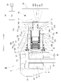
図1に示すように、第1実施形態に係るディスクブレーキ1Aは、車両の回転部(図示略)に取り付けられたディスクロータD(ロータ)を挟んで該ディスクロータDの軸方向両側に配置された一対のインナ及びアウタブレーキパッド2、3と、浮動型のキャリパ4と、を備える。一対のインナ及びアウタブレーキパッド2、3、及び浮動型のキャリパ4は、車両のナックル等の非回転部(図示略)に固定されたキャリア5によって軸方向へ移動可能に支持される。
First, a disc brake 1A according to the first embodiment will be described in detail with reference to FIGS. 1 to 5. FIG.
As shown in FIG. 1, disc brakes 1A according to the first embodiment are arranged on both axial sides of a disc rotor D (rotor) attached to a rotating portion (not shown) of a vehicle. A pair of inner and outer brake pads 2 and 3 and a floating caliper 4 are provided. A pair of inner and outer brake pads 2, 3 and a floating caliper 4 are axially movably supported by a carrier 5 fixed to a non-rotating part (not shown) such as a knuckle of the vehicle.
キャリパ4の主体であるキャリパ本体6は、基端側(一端側)に形成されたシリンダ部7と、該シリンダ部7からディスクロータDを跨ぐように他端側に延び、その先端側(他端側)に形成された爪部8と、を有する。シリンダ部7には、ピストン18が軸方向に沿って摺動可能に嵌装されるシリンダ10が形成される。シリンダ10は、他端側が開口された大径開口部10Aと、一端側が軸孔12を有する底部13によって閉じられた有底の小径開口部10Bと、を有する。シリンダ10の底面には、後述するナット部材77に設けたストッパ突起部160が係合される係合凹部(図示略)が形成される。シリンダ10の大径開口部10Aで、その他端側の内壁面には環状溝14が形成される。当該環状溝14にピストンシール16が設けられる。
A caliper body 6, which is the main body of the caliper 4, includes a cylinder portion 7 formed on the base end side (one end side), and extending from the cylinder portion 7 to the other end side so as to straddle the disk rotor D, and extending to the other end side (other end side). and a claw portion 8 formed on the end side). A cylinder 10 in which a piston 18 is axially slidably fitted is formed in the cylinder portion 7 . The cylinder 10 has a large-diameter opening 10A whose other end is open, and a bottomed small-diameter opening 10B whose one end is closed by a bottom 13 having a shaft hole 12 . The bottom surface of the cylinder 10 is formed with an engagement recess (not shown) with which a stopper projection 160 provided on a nut member 77, which will be described later, is engaged. An annular groove 14 is formed in the inner wall surface on the other end side of the large-diameter opening 10A of the cylinder 10 . A piston seal 16 is provided in the annular groove 14 .
ピストン18は、円筒部20と底部19とからなるカップ状に形成される。ピストン18は、底部19がインナブレーキパッド2に対向するように配置される。ピストン18は、シリンダ10の大径開口部10Aに軸方向に沿って摺動可能に嵌装される。ピストン18の円筒部20の外周面が、ピストンシール16に接触される。ピストン18とシリンダ10の底部13との間には、ピストンシール16によって区画された液圧室21が形成される。液圧室21には、シリンダ部7に設けられたポート(図示省略)を介して、マスタシリンダ、液圧制御ユニット等の液圧源(図示省略)から液圧が供給される。ピストン18の底部19の外周縁部には、凹部25が形成される。凹部25には、インナブレーキパッド2の背面に形成された凸部26が係合される。これにより、ピストン18は、シリンダ10、延いてはキャリパ本体6に対して相対回転不能となる。ピストン18の底部19と、シリンダ10の大径開口部10Aとの間には、ダストブーツ27が設けられる。ピストン18の底部19であって、その一端側内面には、径方向中央に位置する円形凹部30と、該円形凹部30に連続して一端側へ向かうにつれて拡径される環状の傾斜部31と、が形成される。
The piston 18 is shaped like a cup consisting of a cylindrical portion 20 and a bottom portion 19 . The piston 18 is arranged so that the bottom portion 19 faces the inner brake pad 2 . The piston 18 is axially slidably fitted in the large-diameter opening 10A of the cylinder 10 . The outer peripheral surface of the cylindrical portion 20 of the piston 18 contacts the piston seal 16 . A hydraulic chamber 21 defined by the piston seal 16 is formed between the piston 18 and the bottom 13 of the cylinder 10 . Hydraulic pressure is supplied to the hydraulic pressure chamber 21 from a hydraulic pressure source (not shown) such as a master cylinder or a hydraulic pressure control unit through a port (not shown) provided in the cylinder portion 7 . A recess 25 is formed in the outer peripheral edge of the bottom 19 of the piston 18 . A convex portion 26 formed on the back surface of the inner brake pad 2 is engaged with the concave portion 25 . As a result, the piston 18 becomes non-rotatable relative to the cylinder 10 and, by extension, the caliper body 6 . A dust boot 27 is provided between the bottom portion 19 of the piston 18 and the large diameter opening 10A of the cylinder 10 . A circular concave portion 30 located in the center in the radial direction and an annular inclined portion 31 that is continuous with the circular concave portion 30 and whose diameter increases toward the one end side are formed on the inner surface of the bottom portion 19 of the piston 18 on the one end side. , is formed.
キャリパ本体6には、電動モータ35と減速機構とを内蔵したモータギヤユニット36と、回転直動変換機構としてのピストン推進機構37と、が設けられる。ピストン推進機構37は、モータギヤユニット36の回転運動(出力)を直線運動に変換してピストン18を推進させる(他端側へ移動させる)と共に、該ピストン18を制動位置に保持するものである。モータギヤユニット36には、電動モータ35を制御する電子制御ユニット38が接続される。電子制御ユニット38には、パーキングブレーキのON/OFF時に操作されるパーキングスイッチ39が接続される。なお、電子制御ユニット38は、パーキングスイッチ39の操作によらず、車両側からの信号に基づいてパーキングブレーキを作動させることができる。また、モータギヤユニット36の減速機構は、例えば、平歯多段減速機構及び遊星歯車減速機構等を含む。
The caliper body 6 is provided with a motor gear unit 36 containing an electric motor 35 and a speed reduction mechanism, and a piston propulsion mechanism 37 as a rotation/linear motion conversion mechanism. The piston propulsion mechanism 37 converts the rotational motion (output) of the motor gear unit 36 into linear motion to propel the piston 18 (moves it to the other end) and holds the piston 18 at the braking position. . An electronic control unit 38 that controls the electric motor 35 is connected to the motor gear unit 36 . A parking switch 39 is connected to the electronic control unit 38 to be operated when the parking brake is turned ON/OFF. It should be noted that the electronic control unit 38 can operate the parking brake based on a signal from the vehicle side without operating the parking switch 39 . Also, the reduction mechanism of the motor gear unit 36 includes, for example, a spur-tooth multistage reduction mechanism and a planetary gear reduction mechanism.
図2及び図3も参照して、ピストン推進機構37は、スピンドル48と、滑りねじ係合部45と、ローラねじ機構46と、を備えている。スピンドル48は、一端側に形成される軸部49と、他端側に形成される雄ねじ部50と、軸部49と雄ねじ部50との間に形成されるフランジ部51と、を備えている。スピンドル48の軸部49の一端には多角形軸部53が形成される。本実施形態では、多角形軸部53は六角形軸部に形成される。この多角形軸部53が、モータギヤユニット36の減速機構(例えば、遊星減速歯車機構のキャリア等)に相対回転不能に連結される。これにより、モータギヤユニット36からの回転トルクがスピンドル48に伝達される。なお、スピンドル48の軸部49と、モータギヤユニット36の減速機構との接続は、上述の多角形軸部53による回り止めの他、スプライン、キー等、回転トルクを伝達可能な機械要素を用いることができる。スピンドル48の雄ねじ部50は、その他端面がピストン18の底部19に設けた円形凹部30に近接して配置される。フランジ部51は、円環状で径方向外方に突設される。スピンドル48のフランジ部51の一端面には、スラストボール65の転動凹面54が形成される。スピンドル48のフランジ部51の他端面には、凸部55が周方向に沿って間隔を置いて複数形成される。
2 and 3, the piston driving mechanism 37 includes a spindle 48, a sliding screw engaging portion 45, and a roller screw mechanism 46. As shown in FIG. The spindle 48 includes a shaft portion 49 formed on one end side, a male thread portion 50 formed on the other end side, and a flange portion 51 formed between the shaft portion 49 and the male thread portion 50. . A polygonal shaft portion 53 is formed at one end of the shaft portion 49 of the spindle 48 . In this embodiment, the polygonal shaft portion 53 is formed as a hexagonal shaft portion. The polygonal shaft portion 53 is connected to the reduction mechanism of the motor gear unit 36 (for example, the carrier of the planetary reduction gear mechanism, etc.) so as not to rotate relative to each other. Rotational torque from the motor gear unit 36 is thereby transmitted to the spindle 48 . The connection between the shaft portion 49 of the spindle 48 and the speed reduction mechanism of the motor gear unit 36 uses a mechanical element capable of transmitting rotational torque, such as a spline, a key, etc., in addition to the rotation stop by the polygonal shaft portion 53 described above. be able to. The externally threaded portion 50 of the spindle 48 is positioned with its other end adjacent to a circular recess 30 provided in the bottom 19 of the piston 18 . The flange portion 51 is annular and protrudes radially outward. A rolling concave surface 54 for the thrust ball 65 is formed on one end surface of the flange portion 51 of the spindle 48 . A plurality of projections 55 are formed on the other end surface of the flange portion 51 of the spindle 48 at intervals along the circumferential direction.
シリンダ10の底部13には、スピンドル48の軸部49が挿通される軸孔12が形成される。この軸孔12の内周面に、ガイドスリーブ56が嵌着される。スピンドル48の軸部49は、このガイドスリーブ56を介して、キャリパ本体6によって回転可能に支持される。シリンダ10の軸孔12と、スピンドル48の軸部49との間は、シールリング57によってシールされる。該シールリング57は、ガイドスリーブ56より他端側に配置される。シリンダ10内でその底部13付近にベースプレート60が配置される。ベースプレート60は、径方向中央に軸孔61を有する円環板状に形成される。ベースプレート60は、後述するナット部材77の一端内周側に配置される。詳しくは、ベースプレート60は、スピンドル48のフランジ部51の一端側(転動凹面54)に対向するようにして、ナット部材77の大径ナット部151の一端内周側に配置される。ベースプレート60の軸孔61に、スピンドル48の軸部49が摺動可能に挿通される。ベースプレート60の他端面には、スラストボール65の転動凹面63が形成される。そして、スピンドル48のフランジ部51の一端面に設けた転動凹面54と、ベースプレート60の他端面に設けた転動凹面63の間に、複数のスラストボール65が転動自在に配置される。複数のスラストボール65は、リテーナ66によって周方向へ一定の間隔をあけて保持される。
A bottom portion 13 of the cylinder 10 is formed with a shaft hole 12 through which the shaft portion 49 of the spindle 48 is inserted. A guide sleeve 56 is fitted to the inner peripheral surface of the shaft hole 12 . A shaft portion 49 of the spindle 48 is rotatably supported by the caliper body 6 via the guide sleeve 56 . A seal ring 57 seals between the shaft hole 12 of the cylinder 10 and the shaft portion 49 of the spindle 48 . The seal ring 57 is arranged on the other end side of the guide sleeve 56 . A base plate 60 is positioned within the cylinder 10 near its bottom 13 . The base plate 60 is formed in an annular plate shape having a shaft hole 61 in the center in the radial direction. The base plate 60 is arranged on the inner peripheral side of one end of a nut member 77 which will be described later. Specifically, the base plate 60 is arranged on the inner peripheral side of one end of the large-diameter nut portion 151 of the nut member 77 so as to face the one end side (rolling concave surface 54 ) of the flange portion 51 of the spindle 48 . The shaft portion 49 of the spindle 48 is slidably inserted through the shaft hole 61 of the base plate 60 . A rolling concave surface 63 for a thrust ball 65 is formed on the other end surface of the base plate 60 . A plurality of thrust balls 65 are rotatably arranged between a rolling concave surface 54 provided on one end surface of the flange portion 51 of the spindle 48 and a rolling concave surface 63 provided on the other end surface of the base plate 60 . A plurality of thrust balls 65 are held by retainers 66 at regular intervals in the circumferential direction.
ベースプレート60の一端外周面には、一端側に向かって縮径される傾斜面68が形成される。このベースプレート60の傾斜面68と、後述するナット部材77のリテイニング溝部158との間にC形のリテイニングリング70が装着される。該リテイニングリング70により、ベースプレート60がナット部材77に対して、一端側に移動しないように規制、言い換えれば、他端側に付勢される。該リテイニングリング70は、断面円形をなす穴用止め輪であり、圧縮(縮径)された状態で、ナット部材77のリテイニング溝158に装着される。なお、ベースプレート60の外周面には、ブレーキ液を軸方向へ流通させるための複数個の切欠き部71(図3参照)が形成される。
An inclined surface 68 whose diameter is reduced toward the one end side is formed on the one end outer peripheral surface of the base plate 60 . A C-shaped retaining ring 70 is mounted between the inclined surface 68 of the base plate 60 and a retaining groove portion 158 of a nut member 77, which will be described later. The retaining ring 70 restricts the base plate 60 from moving toward one end of the nut member 77, in other words, biases the base plate 60 toward the other end. The retaining ring 70 is a retaining ring for a hole having a circular cross section, and is mounted in the retaining groove 158 of the nut member 77 in a compressed (reduced diameter) state. A plurality of cutouts 71 (see FIG. 3) are formed on the outer peripheral surface of the base plate 60 for axially circulating the brake fluid.
滑りねじ係合部45は、スピンドル48の雄ねじ部50と、後述するシャフト部材75の雌ねじ部84との間の螺合部にて構成される。滑りねじ係合部45は、スピンドル48がアプライ方向またはリリース方向へ回転されると、シャフト部材75を回転方向、及び軸方向へ移動可能に構成される。なお、滑りねじ係合部45は、逆効率が0以下に設定されており、シャフト部材75に作用する軸方向への推力によってスピンドル48を回転させることができない。すなわち、滑りねじ係合部45は、スピンドル48の回転トルクを、シャフト部材75に軸方向への推力に変換することができるが、シャフト部材75の軸方向への推力を、スピンドル48の回転トルクに変換することはできない。
The sliding screw engaging portion 45 is configured by a threaded portion between the male threaded portion 50 of the spindle 48 and the female threaded portion 84 of the shaft member 75 to be described later. The slide screw engaging portion 45 is configured to be able to move the shaft member 75 in the rotational direction and the axial direction when the spindle 48 is rotated in the apply direction or the release direction. The slip screw engaging portion 45 has a reverse efficiency set to 0 or less, and the axial thrust acting on the shaft member 75 cannot rotate the spindle 48 . That is, the sliding screw engaging portion 45 can convert the rotational torque of the spindle 48 into axial thrust force on the shaft member 75 , but the axial thrust force of the shaft member 75 is converted into the rotational torque of the spindle 48 . cannot be converted to
ローラねじ機構46は、軸部材としてのシャフト部材75と、転動体としてのプラネタリローラ76と、筒状部材としてのナット部材77と、を備えている。シャフト部材75は、円筒状に形成される。シャフト部材75は、スピンドル48の周りに配置される。シャフト部材75は、一端側に形成される小径シャフト部79と、他端側に形成される大径シャフト部80とが一体的に接続されて構成される。小径シャフト部79の外周面と大径シャフト部80の外周面との間には環状段差部81(図2及び図3参照)が形成される。小径シャフト部79の一端面には、周方向へ間隔をあけて複数の凸部82(図3参照)が形成される。このシャフト部材75に設けた複数の凸部82と、スピンドル48のフランジ部51の他端面に設けた複数の凸部55とが干渉したとき、両者の相対回転が規制される。これにより、スピンドル48(雄ねじ部50)の、シャフト部材75(雌ねじ部84)への過度のねじ込みによる固着(噛み込み)が防止される。
The roller screw mechanism 46 includes a shaft member 75 as a shaft member, a planetary roller 76 as a rolling element, and a nut member 77 as a cylindrical member. The shaft member 75 is formed cylindrical. A shaft member 75 is arranged around the spindle 48 . The shaft member 75 is configured by integrally connecting a small-diameter shaft portion 79 formed on one end side and a large-diameter shaft portion 80 formed on the other end side. An annular stepped portion 81 (see FIGS. 2 and 3) is formed between the outer peripheral surface of the small-diameter shaft portion 79 and the outer peripheral surface of the large-diameter shaft portion 80 . A plurality of projections 82 (see FIG. 3) are formed on one end surface of the small-diameter shaft portion 79 at intervals in the circumferential direction. When the plurality of projections 82 provided on the shaft member 75 and the plurality of projections 55 provided on the other end surface of the flange portion 51 of the spindle 48 interfere with each other, relative rotation of the two is restricted. This prevents the spindle 48 (male threaded portion 50) from sticking (biting) due to excessive screwing into the shaft member 75 (female threaded portion 84).
シャフト部材75の小径シャフト部79の一端寄りの外周面には、軸方向に沿って所定ピッチの円環状溝部83が形成される。当該各円環状溝部83が、各プラネタリローラ76の外周面に設けられた各円環状山部110と係合される。小径シャフト部79の内周面には、一端側の所定範囲を除く部位に雌ねじ部84が形成される。この雌ねじ部84に、スピンドル48の雄ねじ部50が螺合されて滑りねじ係合部45として作用する。大径シャフト部80には、その周壁部に径方向に沿って貫通する連通孔86が形成される。該連通孔86は、周方向に沿って間隔を置いて複数形成される。本実施形態では、連通孔86は周方向に沿って180°ピッチで2箇所形成される。大径シャフト部80の他端面には、スラストボール99の転動凹面88が形成される。大径シャフト部80の軸孔は、小径シャフト部79の雌ねじ部84より大径である。この軸孔の他端側には、雌ねじ部84より大径のホルダ嵌合孔89が形成される。このホルダ嵌合孔89に、後述するベアリングホルダ103が嵌着される。
An annular groove portion 83 is formed at a predetermined pitch along the axial direction on the outer peripheral surface of the small-diameter shaft portion 79 of the shaft member 75 near one end. Each annular groove portion 83 is engaged with each annular peak portion 110 provided on the outer peripheral surface of each planetary roller 76 . A female screw portion 84 is formed on the inner peripheral surface of the small-diameter shaft portion 79 except for a predetermined range on the one end side. The male threaded portion 50 of the spindle 48 is screwed into the female threaded portion 84 to act as the slide screw engaging portion 45 . A communication hole 86 is formed through the peripheral wall portion of the large-diameter shaft portion 80 along the radial direction. A plurality of communication holes 86 are formed at intervals along the circumferential direction. In this embodiment, two communication holes 86 are formed at a pitch of 180° along the circumferential direction. A rolling concave surface 88 for the thrust ball 99 is formed on the other end surface of the large-diameter shaft portion 80 . The shaft hole of the large-diameter shaft portion 80 has a larger diameter than the internal thread portion 84 of the small-diameter shaft portion 79 . A holder fitting hole 89 having a diameter larger than that of the female threaded portion 84 is formed at the other end of the shaft hole. A bearing holder 103 , which will be described later, is fitted into the holder fitting hole 89 .
シャフト部材75(大径シャフト部80)の他端面と対向するように、スラストプレート92が配置される。スラストプレート92は、スピンドル48の雄ねじ部50が挿通される軸孔93を有する円環状に形成される。スラストプレート92の軸孔93の内径は、大径シャフト部80のホルダ嵌合孔89の内径に略一致する。スラストプレート92の外周面には、ブレーキ液を軸方向へ流通させるための複数の切欠き部95(図3参照)が形成される。スラストプレート92の他端面には、ピストン18の底部19に設けた傾斜部31に当接される当接面94が形成される。スラストプレート92の一端面には、スラストボール99の転動凹面97が形成される。そして、複数のスラストボール99が、スラストプレート92の転動凹面97と、シャフト部材75(大径シャフト部80)の転動凹面88との間に転動自在に配置される。複数のスラストボール99は、リテーナ100によって周方向へ一定の間隔をあけて保持される。
A thrust plate 92 is arranged to face the other end face of the shaft member 75 (large-diameter shaft portion 80). The thrust plate 92 is formed in an annular shape having a shaft hole 93 through which the male threaded portion 50 of the spindle 48 is inserted. The inner diameter of the shaft hole 93 of the thrust plate 92 substantially matches the inner diameter of the holder fitting hole 89 of the large-diameter shaft portion 80 . A plurality of cutouts 95 (see FIG. 3) are formed on the outer peripheral surface of the thrust plate 92 for axially circulating the brake fluid. A contact surface 94 is formed on the other end surface of the thrust plate 92 to contact the inclined portion 31 provided on the bottom portion 19 of the piston 18 . A rolling concave surface 97 for a thrust ball 99 is formed on one end surface of the thrust plate 92 . A plurality of thrust balls 99 are rotatably arranged between the rolling concave surface 97 of the thrust plate 92 and the rolling concave surface 88 of the shaft member 75 (large-diameter shaft portion 80). A plurality of thrust balls 99 are held by a retainer 100 at regular intervals in the circumferential direction.
スラストプレート92の軸孔93の内周面から大径シャフト部80のホルダ嵌合孔89内に亘って、ベアリングホルダ103が挿通される。ベアリングホルダ103は、円筒状に形成される。ベアリングホルダ103の他端外周面には、径方向外方に突設される環状の環状係止部105が形成される。ベアリングホルダ103は、その外周面に弾性片106が180°ピッチで2箇所設けられている。各弾性片106は、ベアリングホルダ103の外周壁を切り込んで形成される。各弾性片106の先端には、係止爪部107が径方向外方に向かって突設される。係止爪部107は、弾性片106が弾性変形することにより、ベアリングホルダ103の外周面から径方向に沿って出没可能となる。そして、ベアリングホルダ103は、その環状係止部105がスラストプレート92の他端面に当接されると共に、各弾性片106の係止爪部107が、大径シャフト部80の連通孔86内に内側から係合される。このベアリングホルダ103により、スラストプレート92を、リテーナ100を含むスラストボール99と共にシャフト部材75の他端に一体的に保持することができる。
A bearing holder 103 is inserted from the inner peripheral surface of the shaft hole 93 of the thrust plate 92 to the inside of the holder fitting hole 89 of the large-diameter shaft portion 80 . The bearing holder 103 is formed in a cylindrical shape. An annular locking portion 105 projecting radially outward is formed on the outer peripheral surface of the other end of the bearing holder 103 . The bearing holder 103 has two elastic pieces 106 provided on its outer peripheral surface at a pitch of 180°. Each elastic piece 106 is formed by cutting the outer peripheral wall of the bearing holder 103 . A locking claw portion 107 is provided at the tip of each elastic piece 106 so as to protrude radially outward. The locking claw portion 107 can be projected and retracted from the outer peripheral surface of the bearing holder 103 along the radial direction by elastically deforming the elastic piece 106 . The annular locking portion 105 of the bearing holder 103 abuts against the other end surface of the thrust plate 92 , and the locking claw portion 107 of each elastic piece 106 is inserted into the communicating hole 86 of the large-diameter shaft portion 80 . Engaged from the inside. The bearing holder 103 allows the thrust plate 92 and the thrust ball 99 including the retainer 100 to be integrally held at the other end of the shaft member 75 .
シャフト部材75の小径シャフト部79の外周であって各円環状溝部83の周りに、周方向に沿って間隔を置いて複数のプラネタリローラ76が配置される。本実施形態では、プラネタリローラ76は6本配置される。プラネタリローラ76には、その外周面に軸方向に沿って所定ピッチの円環状山部110が形成される。プラネタリローラ76の各円環状山部110が、シャフト部材75(小径シャフト部79)の外周面に設けた各円環状溝部83に係合される。これにより、シャフト部材75と各プラネタリローラ76とは、軸方向への相対移動が規制される。これらプラネタリローラ76は、ローラケージ120によって保持される。
A plurality of planetary rollers 76 are arranged at intervals along the circumferential direction around each annular groove portion 83 on the outer periphery of the small-diameter shaft portion 79 of the shaft member 75 . In this embodiment, six planetary rollers 76 are arranged. Annular peaks 110 are formed on the outer peripheral surface of the planetary roller 76 at a predetermined pitch along the axial direction. Each annular peak portion 110 of the planetary roller 76 is engaged with each annular groove portion 83 provided on the outer peripheral surface of the shaft member 75 (small-diameter shaft portion 79). As a result, relative axial movement between the shaft member 75 and the planetary rollers 76 is restricted. These planetary rollers 76 are held by a roller cage 120 .
図2~図4に示すように、ローラケージ120は、各プラネタリローラ76を、隣接するプラネタリローラ76が互いに干渉しないように保持するものである。このローラケージ120は、シャフト部材75の周りに該シャフト部材75に対して回転自在で、且つ後述するナット部材77に対して軸方向に摺動自在に支持される。ローラケージ120は、円筒状に形成される。ローラケージ120の内径は、シャフト部材75の小径シャフト部79(各円環状溝部83)の外径よりも若干大径である。ローラケージ120の周壁部には、プラネタリローラ76をそれぞれ収容するローラ収容孔121が周方向に沿って間隔を置いて形成される。ローラ収容孔121は、プラネタリローラ76の数量に対応して複数形成される。本実施形態では、ローラ収容孔121は、プラネタリローラ76の数量に対応して6箇所形成される。
As shown in FIGS. 2-4, the roller cage 120 holds each planetary roller 76 so that adjacent planetary rollers 76 do not interfere with each other. The roller cage 120 is supported around the shaft member 75 so as to be rotatable relative to the shaft member 75 and axially slidable relative to a nut member 77 which will be described later. Roller cage 120 is formed in a cylindrical shape. The inner diameter of the roller cage 120 is slightly larger than the outer diameter of the small-diameter shaft portion 79 (each annular groove portion 83 ) of the shaft member 75 . Roller housing holes 121 for housing the planetary rollers 76 are formed in the peripheral wall portion of the roller cage 120 at intervals along the circumferential direction. A plurality of roller housing holes 121 are formed corresponding to the number of planetary rollers 76 . In this embodiment, six roller housing holes 121 are formed corresponding to the number of planetary rollers 76 .
ローラ収容孔121は、軸方向に長い平面視略矩形状に形成される。ローラ収容孔121により、プラネタリローラ76に対してその周方向に沿う位置を規制するが、ローラ収容孔121とプラネタリローラ76とは軸方向にて接触することはない。図5も参照して、ローラケージ120の環状の他端面は、段差部122を有する螺旋状に延びている。この螺旋状のリード角は、後述するコイルバネ128の一端側(小径コイル部130)のリード角と略同じである。図5(a)も参照して、ローラケージ120の環状の他端面には、螺旋状に延びる終始点に段差部122が形成される。段差部122の深さ(軸方向の長さ)は、後述するコイルバネ128の外径に略一致する。この段差部122に、後述するコイルバネ128の一端部が係合する。図4(a)を参照して、ローラケージ120の一端開口周辺に、シャフト部材75の小径シャフト部79よりも大径の環状凹部123が形成される。該環状凹部123から連続して、他端側に向かって縮径される環状テーパ面124が形成される。なお、各ローラ収容孔121にプラネタリローラ76をそれぞれ収容すると、ローラケージ120の周壁部と、各プラネタリローラ76の径方向中心を結ぶ円形状とが略一致するように配置される。これにより、各プラネタリローラ76とシャフト部材75との係合部、及び各プラネタリローラ76とナット部材77との係合部へのローラケージ120の巻き込みが抑制されて、精度良く各プラネタリローラ76の位置を保持することができる。
The roller housing hole 121 is formed in a substantially rectangular shape elongated in the axial direction. The roller accommodation hole 121 regulates the position of the planetary roller 76 in the circumferential direction, but the roller accommodation hole 121 and the planetary roller 76 do not come into contact with each other in the axial direction. Referring also to FIG. 5 , the other annular end surface of roller cage 120 extends spirally having a stepped portion 122 . The spiral lead angle is substantially the same as the lead angle of one end side (small-diameter coil portion 130) of the coil spring 128, which will be described later. Referring also to FIG. 5( a ), the other annular end surface of roller cage 120 is formed with stepped portion 122 at the end point extending spirally. The depth (length in the axial direction) of the stepped portion 122 substantially matches the outer diameter of the coil spring 128, which will be described later. One end of a coil spring 128 to be described later is engaged with the stepped portion 122 . 4A, an annular recess 123 having a larger diameter than the small-diameter shaft portion 79 of the shaft member 75 is formed around the one end opening of the roller cage 120. As shown in FIG. An annular tapered surface 124 is formed continuously from the annular recess 123 and has a diameter reduced toward the other end. When the planetary rollers 76 are accommodated in the respective roller accommodating holes 121, the peripheral wall portion of the roller cage 120 and the circular shape connecting the centers of the planetary rollers 76 in the radial direction are substantially aligned. As a result, the rolling of the roller cage 120 into the engaging portion between the planetary rollers 76 and the shaft member 75 and the engaging portion between the planetary rollers 76 and the nut member 77 is suppressed. Position can be held.
そして、図2、図4及び図5を参照して、ローラケージ120の螺旋状の他端面と、シャフト部材75の環状段差部81との間であって、シャフト部材75の小径シャフト部79(各円環状溝部83が形成されていない範囲)の周りにコイルバネ128が配置される。当該コイルバネ128は、シャフト部材75がアプライ方向に回転する際には、シャフト部材75の小径シャフト79とローラケージ120との間の必要相対所定トルクに到達するまではシャフト部材75、コイルバネ128及びローラケージ120を一体回転させて、前記必要相対所定トルクを超えると、シャフト部材75とローラケージ120との相対回転を促進させる一方、シャフト部材75がリリース方向に回転する際には、シャフト部材75、コイルバネ128及びローラケージ120を一体回転させるように構成される。当該コイルバネ128は、コイル状部材またはクラッチ部材に相当する。
2, 4 and 5, the small-diameter shaft portion 79 of the shaft member 75 ( A coil spring 128 is arranged around the area where each annular groove 83 is not formed. When the shaft member 75 rotates in the applying direction, the coil spring 128 keeps the shaft member 75, the coil spring 128, and the rollers 128 until the required relative torque between the small-diameter shaft 79 of the shaft member 75 and the roller cage 120 is reached. When the cage 120 is integrally rotated and the required relative torque is exceeded, the relative rotation between the shaft member 75 and the roller cage 120 is accelerated. It is configured to integrally rotate the coil spring 128 and the roller cage 120 . The coil spring 128 corresponds to a coil-shaped member or a clutch member.
コイルバネ128は弾性体であって、不等ピッチで構成される。本実施形態ではコイルバネ128は右巻きにて構成されるが、設計要件に応じて左巻きに構成してもよい。コイルバネ128は、一端側に配置される小径コイル部130と、他端側に配置され、小径コイル部130よりも大径の大径コイル部131とが一体的に接続されて構成される。小径コイル部130は、そのピッチが大径コイル部131のピッチよりも小さい。小径コイル部130は、軸方向に沿ってその内径は略一致している。小径コイル部130の内径は、自由状態では、シャフト部材75の小径シャフト部79(各円環状溝部83が形成される範囲外)の外径よりも小径である。小径コイル部130は、本実施形態では3巻であり、軸方向に密着して形成されているが、設計要件に応じてその巻数及びピッチを変更してもよい。大径コイル部131は、そのピッチが小径コイル部130のピッチよりも大きい。大径コイル部131の内径は、シャフト部材75の大径シャフト部80の外径よりも大径である。大径コイル部131の内径(外径)は、他端側に向かって次第に拡径される。大径コイル部131の自由長(組付前の軸方向の長さ)は、組付後の長さよりも長く形成される。大径コイル部131は、本実施形態では、1巻としているが、設計要件に応じて変更しても良い。
The coil springs 128 are elastic bodies and are arranged at uneven pitches. In this embodiment, the coil spring 128 is configured with a right-handed winding, but may be configured with a left-handed winding depending on design requirements. The coil spring 128 is configured by integrally connecting a small-diameter coil portion 130 arranged on one end side and a large-diameter coil portion 131 arranged on the other end side and having a larger diameter than the small-diameter coil portion 130 . The pitch of the small-diameter coil portion 130 is smaller than the pitch of the large-diameter coil portion 131 . The small-diameter coil portion 130 has substantially the same inner diameter along the axial direction. The inner diameter of the small-diameter coil portion 130 in the free state is smaller than the outer diameter of the small-diameter shaft portion 79 of the shaft member 75 (outside the range where each annular groove portion 83 is formed). The small-diameter coil portion 130 has three turns in the present embodiment, and is formed in close contact in the axial direction, but the number of turns and the pitch may be changed according to design requirements. The pitch of the large-diameter coil portion 131 is larger than the pitch of the small-diameter coil portion 130 . The inner diameter of the large-diameter coil portion 131 is larger than the outer diameter of the large-diameter shaft portion 80 of the shaft member 75 . The inner diameter (outer diameter) of the large-diameter coil portion 131 gradually expands toward the other end. The free length (length in the axial direction before assembly) of the large-diameter coil portion 131 is formed longer than the length after assembly. Although the large-diameter coil portion 131 has one turn in this embodiment, it may be changed according to design requirements.
そして、図4及び図5を参照して、このコイルバネ128の小径コイル部130の一端部がローラケージ120の段差部122に係合されると共に、コイルバネ128の小径コイル部130及び大径コイル部131がシャフト部材75の小径シャフト部79の周りであって、各円環状溝部83が形成される範囲外に巻き付けられる。その結果、コイルバネ128の小径コイル部130の一端側は、ローラケージ120の螺旋状の他端面に当接するように巻き付けられる。また、コイルバネ128の小径コイル部130は、シャフト部材75の小径シャフト部79の外径よりも小径に形成されているために、組付け後、小径コイル部130の範囲では、小径コイル部130により、小径シャフト部79に向かって所定の付勢力が付与される。この付勢力に対応して、シャフト部材75の小径シャフト部79と、コイルバネ128の小径コイル部130との間に摩擦抵抗が増加する。
4 and 5, one end of the small-diameter coil portion 130 of the coil spring 128 is engaged with the step portion 122 of the roller cage 120, and the small-diameter coil portion 130 and the large-diameter coil portion of the coil spring 128 are engaged with each other. 131 is around the small-diameter shaft portion 79 of the shaft member 75 and is wound outside the range where each annular groove portion 83 is formed. As a result, one end side of the small-diameter coil portion 130 of the coil spring 128 is wound so as to come into contact with the spiral other end surface of the roller cage 120 . In addition, since the small-diameter coil portion 130 of the coil spring 128 is formed to have a smaller diameter than the outer diameter of the small-diameter shaft portion 79 of the shaft member 75, the small-diameter coil portion 130 does not move the small-diameter coil portion 130 after assembly. , a predetermined biasing force is applied toward the small-diameter shaft portion 79 . Corresponding to this biasing force, frictional resistance increases between the small-diameter shaft portion 79 of the shaft member 75 and the small-diameter coil portion 130 of the coil spring 128 .
一方、コイルバネ128の大径コイル部131の内径は、シャフト部材75の小径シャフト部79の外径よりも大径に形成されているので、大径コイル部131の範囲では、小径シャフト部79から僅かに浮いた状態となっており、コイルバネ128の大径コイル部131と、シャフト部材75の小径シャフト部79との間で摩擦抵抗はほぼ発生しない。なお、大径コイル部131は、組付後の軸方向の長さが組付前よりも短いので、軸方向に沿って付勢力を付与する状態、すなわちローラケージ120と、シャフト部材75の大径シャフト部80とを軸方向に沿って離れる方向に付勢する状態で組み付けられる。
On the other hand, the inner diameter of the large-diameter coil portion 131 of the coil spring 128 is formed to be larger than the outer diameter of the small-diameter shaft portion 79 of the shaft member 75 . Since they are in a slightly floating state, almost no frictional resistance is generated between the large-diameter coil portion 131 of the coil spring 128 and the small-diameter shaft portion 79 of the shaft member 75 . Since the large-diameter coil portion 131 has a shorter axial length after assembly than before assembly, it is in a state in which a biasing force is applied along the axial direction, that is, when the roller cage 120 and the shaft member 75 are large. It is assembled in a state of urging the diameter shaft portion 80 in a direction away from it along the axial direction.
図4(b)から解るように、シャフト部材75の小径シャフト部79の外周面に設けた円環状溝部83の一端には、C字状のリテイニングリング135が配置される。なお、リテイニングリング135は、自由状態では、小径シャフト部79の円環状溝部83の内径より小径に形成されており、リテイニングリング135を小径シャフト部79の円環状溝部83に装着すると、円環状溝部83に向かって付勢力を付与した状態で装着される。そして、シャフト部材75の小径シャフト部79の周りであって、各円環状溝部83が形成される範囲にローラケージ120が配置されると、リテイニングリング135がローラケージ120の一端開口周辺に設けた環状テーパ面124に当接される。
As can be seen from FIG. 4B, a C-shaped retaining ring 135 is arranged at one end of an annular groove portion 83 provided on the outer peripheral surface of the small-diameter shaft portion 79 of the shaft member 75 . In the free state, the retaining ring 135 has a smaller diameter than the inner diameter of the annular groove portion 83 of the small-diameter shaft portion 79 . It is mounted with a biasing force applied toward the annular groove portion 83 . When the roller cage 120 is arranged around the small-diameter shaft portion 79 of the shaft member 75 and in the range where each annular groove portion 83 is formed, a retaining ring 135 is provided around one end opening of the roller cage 120. It abuts against the annular tapered surface 124 .
これにより、コイルバネ128により、ローラケージ120はシャフト部材75に対して一端側に付勢されるが、リテイニングリング135により、ローラケージ120のシャフト部材75に対する軸方向に沿う移動が規制される。その結果、ローラケージ120の各ローラ収容孔121と各プラネタリローラ76とが軸方向で接触することはない。リテイニングリング135が、シャフト部材75とローラケージ120との軸方向に沿う相対移動を規制する係止部材に相当する。なお、従来から、コイル状の一方向クラッチ等は、コイル部の巻き終わりをフック状に形成して、相手部品に係合させる構成が一般的である。しかしながら、負荷トルクが大きい場合、フック部とコイル部との間の曲げ部に付与される応力が大きくなるため、例えば、一方向クラッチの線径を太くする、または曲げ部分の曲率を大きくする等が必要となり、大型化してしまう課題があった。しかしながら、本実施形態に係るコイルバネ128では、フック部を設けていないので、小型化を達成することができる。なお、このコイルバネ128の作用については、後で詳細に説明する。
As a result, the coil spring 128 urges the roller cage 120 toward one end of the shaft member 75 , but the retaining ring 135 restricts axial movement of the roller cage 120 with respect to the shaft member 75 . As a result, the roller housing holes 121 of the roller cage 120 and the planetary rollers 76 do not contact each other in the axial direction. Retaining ring 135 corresponds to a locking member that restricts axial relative movement between shaft member 75 and roller cage 120 . Conventionally, a coil-shaped one-way clutch or the like generally has a configuration in which the winding end of the coil portion is formed into a hook shape and engaged with a mating component. However, when the load torque is large, the stress applied to the bent portion between the hook portion and the coil portion increases. was required, and there was a problem of increasing in size. However, since the coil spring 128 according to the present embodiment does not have the hook portion, it is possible to achieve miniaturization. The action of this coil spring 128 will be described later in detail.
図1~図3に示すように、ナット部材77は、段付円筒形状に形成される。ナット部材77は、一端側に配置される大径ナット部151と、他端側に配置される小径ナット部152とが一体的に接続されて構成される。図3を参照して、大径ナット部151の一端面からは、ストッパ突起部160が一端側に向かって突設されている。ストッパ突起部160、160は、180°ピッチで互いに対向するように形成されている。各ストッパ突起部160は、断面略矩形状に形成される。これらストッパ突起部160、160が、キャリパ本体6のシリンダ10の底部13に設けた係合凹部にそれぞれ係合される。これにより、ナット部材77は、キャリパ本体6(シリンダ部7)に対する相対回転が規制される。大径ナット部151の一端は、シリンダ10の底部13に近接した位置に配置される。大径ナット部151には、その周壁部を径方向に貫通してブレーキ液を流通させる通路157が周方向に沿って間隔を置いて複数設けられる。大径ナット部151の内周面には、リテイニングリング70が装着される、環状のリテイニング溝部158が形成される。小径ナット部152の他端は、軸方向で、シャフト部材75に設けた連通孔86よりの若干他端側に位置する。小径ナット部152の内周面には雌ねじ部155が形成される。この雌ねじ部155は、小径ナット部152の軸方向略全域に亘って設けられている。
As shown in FIGS. 1 to 3, the nut member 77 is formed in a stepped cylindrical shape. The nut member 77 is configured by integrally connecting a large-diameter nut portion 151 arranged on one end side and a small-diameter nut portion 152 arranged on the other end side. Referring to FIG. 3, a stopper protrusion 160 protrudes from one end face of large-diameter nut portion 151 toward the one end side. The stopper protrusions 160, 160 are formed to face each other at a pitch of 180°. Each stopper protrusion 160 is formed to have a substantially rectangular cross section. These stopper protrusions 160, 160 are engaged with engagement recesses provided in the bottom portion 13 of the cylinder 10 of the caliper body 6, respectively. As a result, the nut member 77 is restricted from rotating relative to the caliper body 6 (cylinder portion 7). One end of the large-diameter nut portion 151 is arranged at a position close to the bottom portion 13 of the cylinder 10 . In the large-diameter nut portion 151, a plurality of passages 157 are provided at intervals along the circumferential direction so as to pass through the peripheral wall portion in the radial direction and circulate the brake fluid. An annular retaining groove portion 158 to which the retaining ring 70 is attached is formed on the inner peripheral surface of the large-diameter nut portion 151 . The other end of the small-diameter nut portion 152 is located slightly on the other end side of the communication hole 86 provided in the shaft member 75 in the axial direction. A female threaded portion 155 is formed on the inner peripheral surface of the small diameter nut portion 152 . The female threaded portion 155 is provided over substantially the entire axial region of the small-diameter nut portion 152 .
このナット部材77の雌ねじ部155が、各プラネタリローラ76の各円環状山部110と係合される(噛み合わされる)。ナット部材77の雌ねじ部155とプラネタリローラ76の各円環状山部110とは、雌ねじ部155のピッチと各円環状山部110のピッチ(軸方向間隔)とが同一で、かつ雌ねじ部155の条数をプラネタリローラ76の数量の整数倍に設定することにより、相互に噛み合わされる。例えば、6個のプラネタリローラ76を用いて、雌ねじ部155及び各円環状山部110のピッチを1mmとした場合、雌ねじ部155の条数を6(6個×1倍)に設定することにより、ナット部材77の雌ねじ部155とプラネタリローラ76の各円環状山部110とを噛み合わせることができる。なお、このときのリードは6mmである。
The female threaded portion 155 of the nut member 77 is engaged (engaged) with each annular peak portion 110 of each planetary roller 76 . The female screw portion 155 of the nut member 77 and the annular ridge portions 110 of the planetary roller 76 have the same pitch (axial interval) between the female screw portion 155 and the annular ridge portions 110, and the female screw portion 155 has the same pitch. By setting the number of threads to an integral multiple of the number of planetary rollers 76, they are meshed with each other. For example, when six planetary rollers 76 are used and the pitch of the female threaded portion 155 and each annular ridge portion 110 is set to 1 mm, the number of threads of the female threaded portion 155 is set to 6 (6 x 1). , the female threaded portion 155 of the nut member 77 and the annular ridges 110 of the planetary roller 76 can be meshed with each other. Note that the lead at this time is 6 mm.
次に、第1実施形態のディスクブレーキ1Aの作用を説明する。
運転者によってブレーキペダル(図示略)が踏み込まれると、ブレーキペダルの踏力に応じた液圧が、マスタシリンダ、液圧回路(以上、図示省略)を経由し、キャリパ本体6(シリンダ10)内の液圧室21へ供給される。これにより、ピストン18は、ピストンシール16を弾性変形させながら、非制動時の原位置から他端側へ移動し、インナブレーキパッド2をディスクロータDに押し付ける。続いて、キャリパ4は、ピストン18の反力によってキャリア5に対して一端側へ移動し、爪部8に当接されたアウタブレーキパッド3をディスクロータDに押し付ける。その結果、ディスクロータDが一対のインナ及びアウタブレーキパッド2、3によって挟み付けられて摩擦力が発生して、車両の制動力が発生する。
Next, the action of the disc brake 1A of the first embodiment will be described.
When the driver depresses the brake pedal (not shown), the hydraulic pressure corresponding to the force applied to the brake pedal is applied to the caliper body 6 (cylinder 10) via the master cylinder and the hydraulic circuit (not shown). It is supplied to the hydraulic chamber 21 . As a result, the piston 18 moves from its original position during non-braking to the other end side while elastically deforming the piston seal 16 , and presses the inner brake pad 2 against the disc rotor D. Subsequently, the caliper 4 moves to one end side with respect to the carrier 5 by the reaction force of the piston 18, and presses the outer brake pad 3, which is in contact with the claw portion 8, against the disc rotor D. As shown in FIG. As a result, the disk rotor D is sandwiched between the pair of inner and outer brake pads 2 and 3 to generate a frictional force, thereby generating braking force for the vehicle.
一方、運転者によってブレーキペダルが戻されると、マスタシリンダから液圧室21への液圧の供給が停止し、液圧室21内の液圧が低下する。これにより、ピストン18が、ピストンシール16の弾性変形の復元力によって原位置まで後退し、車両の制動力が解除される。なお、インナ及びアウタブレーキパッド2、3の摩耗に伴って、ピストン18の移動量が増大してピストンシール16の弾性変形の限界を越えると、ピストン18とピストンシール16との間に滑りが生じ、当該滑りによってキャリパ本体6に対するピストン18の原位置が移動する。これにより、インナ及びアウタブレーキパッド2、3が摩耗した場合でも、パッドクリアランスが一定に調整される。
On the other hand, when the driver releases the brake pedal, the supply of hydraulic pressure from the master cylinder to the hydraulic pressure chamber 21 is stopped, and the hydraulic pressure in the hydraulic pressure chamber 21 decreases. As a result, the piston 18 is retracted to the original position by the restoring force of the elastic deformation of the piston seal 16, and the braking force of the vehicle is released. If the amount of movement of the piston 18 increases as the inner and outer brake pads 2, 3 wear and the limit of elastic deformation of the piston seal 16 is exceeded, slippage occurs between the piston 18 and the piston seal 16. , the original position of the piston 18 relative to the caliper body 6 is moved by the slippage. Thereby, even when the inner and outer brake pads 2, 3 are worn, the pad clearance is adjusted to be constant.
次に、第1実施形態に係るディスクブレーキ1Aによる、車両の停止状態を維持するパーキングブレーキの作用を説明する。
電子制御ユニット38は、パーキングブレーキの解除状態からパーキングスイッチ39の操作等によるアプライ指令(パーキングブレーキ作動指令)を受けると、モータギヤユニット36の電動モータ35へ通電してスピンドル48をアプライ方向へ回転させる。スピンドル48へ伝達された回転トルクは、スピンドル48の雄ねじ部50とシャフト部材75の雌ねじ部84との滑りねじ係合部45を介して、シャフト部材75(ローラねじ機構46)へ伝達される。なお、シャフト部材75には、スピンドル48から伝達される回転トルクに対して、各プラネタリローラ76からの回転抵抗トルクが反力として付与されるため、シャフト部材75は、スピンドル48に対して相対回転すると共に、他端側(アプライ方向)への軸方向推力が付与される。
Next, the operation of the parking brake that maintains the stopped state of the vehicle by the disc brake 1A according to the first embodiment will be described.
When the electronic control unit 38 receives an apply command (parking brake activation command) by operating the parking switch 39 or the like from the parking brake released state, the electric motor 35 of the motor gear unit 36 is energized to rotate the spindle 48 in the apply direction. Let The rotational torque transmitted to the spindle 48 is transmitted to the shaft member 75 (roller screw mechanism 46 ) via the slide screw engagement portion 45 between the male threaded portion 50 of the spindle 48 and the female threaded portion 84 of the shaft member 75 . Since the rotation torque transmitted from the spindle 48 is given to the shaft member 75 as a reaction force by the rotation resistance torque from each planetary roller 76, the shaft member 75 rotates relative to the spindle 48. At the same time, an axial thrust toward the other end (apply direction) is applied.
シャフト部材75(ローラねじ機構46)へ伝達された回転トルクは、シャフト部材75の各円環状溝部83とプラネタリローラ76の各円環状山部110との係合部を介して、プラネタリローラ76へ伝達される。プラネタリローラ76へ伝達された回転トルクは、プラネタリローラ76の各円環状山部110とナット部材77の雌ねじ部155との係合部(噛み合い部)を介して、ナット部材77へ伝達される。ナット部材77は、各ストッパ突起部160、160と各収容凹部との係合により、シリンダ部7に対して相対回転不能に支持されているために、各プラネタリローラ76は、自身の回転軸を中心に自転しながらナット部材77の軸線を中心にアプライ方向へ公転する(ローラケージ120も共に回転する)。このとき、各プラネタリローラ76には、伝達された回転トルクに応じた他端側への軸方向推力が発生する。各プラネタリローラ76に発生した推力は、プラネタリローラ76の各円環状山部110とシャフト部材75の各円環状溝部83との係合部を介して、シャフト部材75へ伝達される。その結果、シャフト部材75が回転しながら他端側(アプライ方向)へ移動する。
The rotational torque transmitted to the shaft member 75 (roller screw mechanism 46) is transmitted to the planetary roller 76 via the engaging portions between the annular grooves 83 of the shaft member 75 and the annular ridges 110 of the planetary roller 76. transmitted. The rotational torque transmitted to the planetary roller 76 is transmitted to the nut member 77 via the engaging portions (meshing portions) between the annular ridges 110 of the planetary roller 76 and the female threaded portion 155 of the nut member 77 . Since the nut member 77 is supported so as not to rotate relative to the cylinder portion 7 by engaging the stopper protrusions 160 and 160 with the accommodation recesses, each planetary roller 76 rotates its own rotating shaft. It revolves in the apply direction around the axis of the nut member 77 while rotating about its axis (the roller cage 120 also rotates together). At this time, each planetary roller 76 generates an axial thrust toward the other end in accordance with the transmitted rotational torque. The thrust force generated in each planetary roller 76 is transmitted to the shaft member 75 via the engaging portions between the annular ridges 110 of the planetary rollers 76 and the annular grooves 83 of the shaft member 75 . As a result, the shaft member 75 rotates and moves toward the other end (apply direction).
なお、スピンドル48の雄ねじ部50とシャフト部材75の雌ねじ部84との間の滑りねじ係合部45では、シャフト部材75からプラネタリローラ76へ伝達される回転トルクとほぼ等しい回転トルクを、スピンドル48からシャフト部材75へ伝達している。このため、上述したように、滑りねじ係合部45には、伝達トルクに応じた他端側への軸方向推力が発生する。当該滑りねじ係合部45に発生した軸方向推力により、シャフト部材75は、スピンドル48に対して他端側への軸方向推力を受ける。このように、シャフト部材75は、滑りねじ係合部45においてスピンドル48から伝達される回転トルクによる他端側への軸方向推力と、ローラねじ機構46のナット部材77と各プラネタリローラ76との間に発生した他端側への軸方向推力と、を合わせた軸方向推力を受ける。
At the slide screw engaging portion 45 between the male threaded portion 50 of the spindle 48 and the female threaded portion 84 of the shaft member 75 , a rotational torque substantially equal to the rotational torque transmitted from the shaft member 75 to the planetary roller 76 is applied to the spindle 48 . to the shaft member 75. Therefore, as described above, an axial thrust toward the other end is generated in the slide screw engaging portion 45 according to the transmission torque. Due to the axial thrust generated in the slide screw engaging portion 45 , the shaft member 75 receives an axial thrust toward the other end of the spindle 48 . In this way, the shaft member 75 is driven by the axial thrust toward the other end due to the rotational torque transmitted from the spindle 48 at the slide screw engaging portion 45 and the force generated by the nut member 77 of the roller screw mechanism 46 and each planetary roller 76 . It receives an axial thrust that is the sum of the axial thrust toward the other end generated between them.
これらの他端側(アプライ方向)への軸方向推力を受けたシャフト部材75は、ナット部材77の雌ねじ部155に沿うように回転しながら他端側(アプライ方向)へ移動し、スラストボール99を介してスラストプレート92の当接面94をピストン18の底部19の傾斜部31に押し付ける。これにより、ピストン18は、他端側(アプライ方向)へ移動し、インナブレーキパッド2を押圧する。その結果、インナ及びアウタブレーキパッド2、3によりディスクロータDが押圧されて、車両の制動力が発生する。電子制御ユニット38は、シャフト部材75がピストン18を押圧する力、換言すると、車両の制動力が、予め定められた所定値に到達すると、モータギヤユニット36の電動モータ35への通電を停止し、スピンドル48のアプライ方向への駆動(回転)を停止させる。なお、電子制御ユニット38は、シャフト部材75がピストン18を押圧する力(シャフト部材75の推力)を、例えば、電動モータ35の電流値に基づき算出することができる。
The shaft member 75 that receives the axial thrust toward the other end (apply direction) rotates along the female threaded portion 155 of the nut member 77 and moves toward the other end (apply direction). , the contact surface 94 of the thrust plate 92 is pressed against the inclined portion 31 of the bottom portion 19 of the piston 18 . As a result, the piston 18 moves toward the other end (apply direction) and presses the inner brake pad 2 . As a result, the disk rotor D is pressed by the inner and outer brake pads 2 and 3, and braking force of the vehicle is generated. The electronic control unit 38 stops energizing the electric motor 35 of the motor gear unit 36 when the force with which the shaft member 75 presses the piston 18, in other words, the braking force of the vehicle reaches a predetermined value. , stop the driving (rotation) of the spindle 48 in the applying direction. Note that the electronic control unit 38 can calculate the force with which the shaft member 75 presses the piston 18 (thrust force of the shaft member 75) based on the current value of the electric motor 35, for example.
このアプライ時、インナ及びアウタブレーキパッド2、3によりディスクロータDを押圧する前段階では、インナ及びアウタブレーキパッド2、3によるディスクロータDへの押圧力からの反力が付与されないために、シャフト部材75のスピンドル48に対する相対回転トルクは小さい。そのために、インナ及びアウタブレーキパッド2、3によりディスクロータDを押圧する前段階においては、シャフト部材75がアプライ方向に回転すると、コイルバネ128の一端部がローラケージ120の段差部122に係合して、またシャフト部材75とコイルバネ128の小径コイル部130との間の摩擦抵抗も付与され、さらにシャフト部材75とローラケージ120との間における必要相対回転トルクにも到達していないので、シャフト部材75、コイルバネ128及びローラケージ120(各プラネタリローラ76を含む)は一体となって共回りする。その結果、この段階では、ローラねじ機構46は、早送りねじ機構として作用するので、アプライ開始からインナ及びアウタブレーキパッド2、3によりディスクロータDを押し付けるまでの時間を短縮することができる。
At the time of this application, in the stage before the disk rotor D is pressed by the inner and outer brake pads 2, 3, the reaction force from the pressing force on the disk rotor D by the inner and outer brake pads 2, 3 is not applied. The relative rotational torque of member 75 to spindle 48 is small. Therefore, when the shaft member 75 rotates in the applying direction, one end of the coil spring 128 engages with the stepped portion 122 of the roller cage 120 before the disk rotor D is pressed by the inner and outer brake pads 2 and 3 . Frictional resistance is also applied between the shaft member 75 and the small-diameter coil portion 130 of the coil spring 128, and the required relative rotational torque between the shaft member 75 and the roller cage 120 is not reached. 75, coil springs 128 and roller cage 120 (including each planetary roller 76) co-rotate together. As a result, at this stage, the roller screw mechanism 46 acts as a rapid feed screw mechanism, so the time from the start of applying to the disc rotor D being pressed by the inner and outer brake pads 2, 3 can be shortened.
続いて、インナ及びアウタブレーキパッド2、3によりディスクロータDを押し付ける制動力発生域に到達すると、インナ及びアウタブレーキパッド2、3によるディスクロータDへの押圧力からの反力(軸方向に沿う反力)がローラねじ機構46に付与される。すると、シャフト部材75とローラケージ120との間における必要相対回転トルクを超えた時点で、コイルバネ128の小径コイル部130が拡径され、コイルバネ128の小径コイル部130とシャフト部材75の小径シャフト部79との間の摩擦力が低下する。その結果、シャフト部材75とローラケージ120とが容易に相対回転して、言い換えれば、ローラねじ機構46が遊星減速運動して、ねじ効率が50%以上の高い効率となり、シャフト部材75の他端側への推進力が増力される。なお、シャフト部材75とローラケージ120との間における必要相対回転トルクの大きさは、コイルバネ128の線径、内径及び巻数によって適宜調整可能である。
Subsequently, when the braking force generation region in which the inner and outer brake pads 2 and 3 press the disc rotor D is reached, the reaction force from the pressing force to the disc rotor D by the inner and outer brake pads 2 and 3 (along the axial direction reaction force) is applied to the roller screw mechanism 46 . Then, when the required relative rotational torque between the shaft member 75 and the roller cage 120 is exceeded, the diameter of the small-diameter coil portion 130 of the coil spring 128 is expanded, and the small-diameter coil portion 130 of the coil spring 128 and the small-diameter shaft portion of the shaft member 75 are expanded. 79 is reduced. As a result, the shaft member 75 and the roller cage 120 are easily rotated relative to each other. The propulsive force to the side is increased. The magnitude of the relative rotational torque required between the shaft member 75 and the roller cage 120 can be appropriately adjusted by the wire diameter, inner diameter, and number of turns of the coil spring 128 .
なお、上述したように、アプライ方向にシャフト部材75を回転させ、シャフト部材75とローラケージ120との間における必要相対回転トルクを超えると、コイルバネ128の小径コイル部130とシャフト部材75の小径シャフト部79との間の摩擦力が低下するので、コイルバネ128の大径コイル部131の軸方向に沿う付勢力によって、容易にローラケージ120を一端側に付勢することができる。すなわち、シャフト部材75とローラケージ120とが相対回転する際には、コイルバネ128、ローラケージ120及びリテイニングリング135の軸方向に沿うそれぞれの隙間を無くすことができる。これにより、部品製造時の寸法ばらつきだけでなく、各部材の当接箇所の摩耗により寸法変化(劣化)にも影響されることはない。
As described above, when the shaft member 75 is rotated in the apply direction and the required relative rotational torque between the shaft member 75 and the roller cage 120 is exceeded, the small-diameter coil portion 130 of the coil spring 128 and the small-diameter shaft of the shaft member 75 are rotated. Since the frictional force with the portion 79 is reduced, the roller cage 120 can be easily urged toward one end by the urging force along the axial direction of the large-diameter coil portion 131 of the coil spring 128 . That is, when the shaft member 75 and the roller cage 120 rotate relative to each other, the respective gaps along the axial direction of the coil spring 128, the roller cage 120 and the retaining ring 135 can be eliminated. As a result, it is not affected by dimensional variation (deterioration) due to wear of contact portions of the members, as well as dimensional variations during part manufacturing.
また、前述したように、滑りねじ係合部45は、逆効率が0以下であるので、スピンドル48の回転トルクをシャフト部材75の他端側への軸方向推力に変換することができるが、シャフト部材75への軸方向推力をスピンドル48の回転トルクに変換することができない。これにより、電子制御ユニット38が電動モータ35への通電を停止したとき、シャフト部材75は、ピストン18を介してディスクロータDからの押圧力の反力が作用しても、停止状態を維持することができる。その結果、ピストン18が制動位置に保持され、パーキングブレーキの作動が完了する。パーキングブレーキの作動が完了した状態では、ディスクロータDからの押圧力の反力が、スラストプレート92、スラストボール99、シャフト部材75、スピンドル48、スラストボール65、およびベースプレート60を介してキャリパ本体6のシリンダ10の底部13へ伝達され、ピストン18の保持力となる。
Further, as described above, since the slip screw engaging portion 45 has a reverse efficiency of 0 or less, it can convert the rotational torque of the spindle 48 into an axial thrust toward the other end of the shaft member 75. Axial thrust to the shaft member 75 cannot be converted into rotational torque of the spindle 48 . As a result, when the electronic control unit 38 stops energizing the electric motor 35, the shaft member 75 maintains the stopped state even if the reaction force of the pressing force from the disk rotor D acts via the piston 18. be able to. As a result, the piston 18 is held in the braking position and the parking brake operation is completed. When the parking brake is fully activated, the reaction force of the pressing force from the disk rotor D is applied to the caliper body 6 via the thrust plate 92, thrust balls 99, shaft member 75, spindle 48, thrust balls 65, and base plate 60. is transmitted to the bottom portion 13 of the cylinder 10 and serves as a holding force for the piston 18 .
一方、電子制御ユニット38が、パーキングスイッチ39の操作等のリリース指令(パーキングブレーキ解除指令)を受けると、モータギヤユニット36の電動モータ35へ通電し、スピンドル48をリリース方向へ回転させる。このスピンドル48へ伝達された回転トルクは、スピンドル48の雄ねじ部50とシャフト部材75の雌ねじ部84との滑りねじ係合部45を介して、シャフト部材75へ伝達されて、該シャフト部材75がリリース方向に一体回転して、ローラねじ機構46(シャフト部材75と各プラネタリローラ76との係合部、及び各プラネタリローラ76とナット部材77との係合部)へのインナ及びアウタブレーキパッド2、3によるディスクロータDへの押圧力からの反力がほぼ無くなる。つまり、スピンドル48の雄ねじ部50と、シャフト部材75の雌ねじ部84との間の滑りねじ係合部45の始動トルクは、早送りねじ機構として機能するローラねじ機構46の始動トルクよりも大きくなるように設定されている。そのために、リリース時には、ローラねじ機構46が滑りねじ係合部45よりも先に作動するために、スピンドル48をリリース方向へ回転させると、シャフト部材75がスピンドル48と共に一体回転する。そして、シャフト部材75の各円環状溝部83と、プラネタリローラ76の各円環状山部110と、ナット部材77の雌ねじ部155とがリリース方向に係合する。さらに、シャフト部材75が回転すると、ローラねじ機構46が遊星減速運動しようとして、各プラネタリローラ76がローラ収容孔121と周方向に当接する。
On the other hand, when the electronic control unit 38 receives a release command (parking brake release command) such as operation of the parking switch 39, it energizes the electric motor 35 of the motor gear unit 36 to rotate the spindle 48 in the release direction. The rotational torque transmitted to the spindle 48 is transmitted to the shaft member 75 via the sliding screw engaging portion 45 between the male threaded portion 50 of the spindle 48 and the female threaded portion 84 of the shaft member 75, and the shaft member 75 is The inner and outer brake pads 2 rotate integrally in the release direction to the roller screw mechanism 46 (the engaging portion between the shaft member 75 and each planetary roller 76 and the engaging portion between each planetary roller 76 and the nut member 77). , 3 to the disk rotor D is substantially eliminated. That is, the starting torque of the slide screw engaging portion 45 between the male threaded portion 50 of the spindle 48 and the female threaded portion 84 of the shaft member 75 is set to be larger than the starting torque of the roller screw mechanism 46 functioning as a rapid feed screw mechanism. is set to Therefore, when releasing, the roller screw mechanism 46 operates before the sliding screw engagement portion 45 , so that when the spindle 48 is rotated in the releasing direction, the shaft member 75 rotates integrally with the spindle 48 . Then, each annular groove portion 83 of the shaft member 75, each annular peak portion 110 of the planetary roller 76, and the female thread portion 155 of the nut member 77 are engaged in the releasing direction. Further, when the shaft member 75 rotates, the roller screw mechanism 46 tries to perform a planetary deceleration motion, and each planetary roller 76 comes into contact with the roller housing hole 121 in the circumferential direction.
このとき、シャフト部材75に対しローラケージ120は遅れて回転(相対回転)しようとして、コイルバネ128のリード角に沿って一端側に移動しようとする。しかしながら、ローラケージ120は、リテイニングリング135によって一端側への移動が規制されているため、結果として相対回転できない。このように、シャフト部材75がリリース方向に回転すると、ローラケージ120は軸方向に移動できないために、シャフト部材75、コイルバネ128及びローラケージ120(各プラネタリローラ76を含む)は一体となってリリース方向に回転する。続いて、シャフト部材75へ伝達された回転トルクは、コイルバネ128及びローラケージ120を介して、プラネタリローラ76へ伝達される。
At this time, the roller cage 120 attempts to rotate (relatively rotate) with respect to the shaft member 75 with a delay, and attempts to move toward one end along the lead angle of the coil spring 128 . However, since the roller cage 120 is restricted from moving toward one end by the retaining ring 135, the roller cage 120 cannot relatively rotate. Thus, when the shaft member 75 rotates in the release direction, the roller cage 120 cannot move in the axial direction, so the shaft member 75, the coil spring 128, and the roller cage 120 (including the planetary rollers 76) are united to release. rotate in the direction Subsequently, the rotational torque transmitted to shaft member 75 is transmitted to planetary roller 76 via coil spring 128 and roller cage 120 .
プラネタリローラ76へ伝達された回転トルクは、各プラネタリローラ76の各円環状山部110とナット部材77の各雌ねじ部155との係合部(噛み合い部)を介して、ナット部材77へ伝達される。ナット部材77は、各ストッパ突起部160、160と各収容凹部との係合により、シリンダ部7に対して相対回転不能に支持されているために、各プラネタリローラ76は、その各円環状山部110と雌ねじ部155とが滑りながらナット部材77の軸線を中心にリリース方向へ公転する(ローラケージ120も共に回転)。このとき、各プラネタリローラ76には、伝達された回転トルクに応じてリリース方向への軸方向推力が発生する。各プラネタリローラ76に発生した軸方向推力は、各プラネタリローラ76の各円環状山部110とシャフト部材75の各円環状溝部83との係合部を介して、シャフト部材75へ伝達される。
The rotational torque transmitted to the planetary rollers 76 is transmitted to the nut member 77 via the engaging portions (meshing portions) between the annular ridges 110 of the planetary rollers 76 and the female threads 155 of the nut member 77. be. The nut member 77 is supported so as not to rotate relative to the cylinder portion 7 by engaging the stopper projections 160 and 160 with the accommodation recesses. The portion 110 and the female screw portion 155 revolve around the axis of the nut member 77 in the release direction while sliding (the roller cage 120 rotates together). At this time, each planetary roller 76 generates axial thrust in the release direction according to the transmitted rotational torque. The axial thrust force generated in each planetary roller 76 is transmitted to the shaft member 75 via the engagement portion between each annular peak portion 110 of each planetary roller 76 and each annular groove portion 83 of the shaft member 75 .
このリリース時、ローラねじ機構46では、遊星減速運動はせずに、各プラネタリローラ76がローラケージ120と共にシャフト部材75と一体回転することで、効率の低い早送りねじ機構として作用して、シャフト部材75がナット部材77に対してリリース方向に移動する。またその際、ローラねじ機構46は、効率の低いねじ機構として作用しているために、付与される回転トルクに対して発生する軸力が小さくなる。その結果、ローラねじ機構46の作動によって発生する、滑りねじ係合部45を締め付ける力を小さく抑えることができる。このように、リリース時には、ローラねじ機構46の効率を低下させ、モータギヤユニット36からスピンドル48に入力された回転トルクに対して、ローラねじ機構46の作動に伴って滑りねじ係合部45に発生する軸力を抑制することができる。
When the roller screw mechanism 46 is released, the planetary rollers 76 rotate integrally with the shaft member 75 together with the roller cage 120 without performing a planetary deceleration motion. 75 moves relative to the nut member 77 in the release direction. At this time, since the roller screw mechanism 46 acts as a screw mechanism with low efficiency, the axial force generated with respect to the applied rotational torque is reduced. As a result, the force that tightens the slide screw engaging portion 45 generated by the operation of the roller screw mechanism 46 can be suppressed. In this way, at the time of release, the efficiency of the roller screw mechanism 46 is reduced, and the rotation torque input from the motor gear unit 36 to the spindle 48 is applied to the slide screw engaging portion 45 as the roller screw mechanism 46 operates. The generated axial force can be suppressed.
その後、シャフト部材75がインナ及びアウタブレーキパッド2、3によりディスクロータDを押し付ける制動力発生域からリリース方向に移動して、モータギヤユニット36からスピンドル48に入力される回転トルクに対して、滑りねじ係合部45の作動トルクに到達すると、スピンドル48とシャフト部材75(コイルバネ120及びローラケージ120も共に回転)とが相対回転することで、シャフト部材75がスピンドル48に対してリリース方向に移動する。なお、リリース時、インナ及びアウタブレーキパッド2、3によるディスクロータDへの押圧力からの反力の有無に関係なく、ローラねじ機構46は早送りねじ機構として作動するために、リリース作動時間を短縮することができる。
After that, the shaft member 75 moves in the releasing direction from the braking force generation area where the disc rotor D is pressed by the inner and outer brake pads 2 and 3, and slips against the rotational torque input from the motor gear unit 36 to the spindle 48. When the operating torque of the screw engagement portion 45 is reached, the spindle 48 and the shaft member 75 (both the coil spring 120 and the roller cage 120 also rotate) rotate relative to each other, so that the shaft member 75 moves in the release direction with respect to the spindle 48. do. When releasing, the roller screw mechanism 46 operates as a rapid feed screw mechanism regardless of the presence or absence of a reaction force from the pressing force of the inner and outer brake pads 2, 3 on the disc rotor D, thereby shortening the release operation time. can do.
そして、シャフト部材75のリリース方向への移動により、インナ及びアウタブレーキパッド2、3によるディスクロータDの押圧力が解除される。電子制御ユニット38は、ピストン18の底部19の傾斜部31とスラストプレート92の当接面94との間に予め定められた距離(クリアランス)が確保された初期状態に戻ると、モータギヤユニット36の電動モータ35への通電を停止する。なお、リリース作動時には、シャフト部材75がスピンドル48に対して相対回転しながら一端側に移動するが、シャフト部材75の一端面に形成した凸部82が、スピンドル48のフランジ部51の他端面の凸部55に係合されることで、シャフト部材75のスピンドル48に対する相対回転が規制される。これにより、スピンドル48の雄ねじ部50の、シャフト部材75の雌ねじ部84への過度なねじ込みが抑制される。
By moving the shaft member 75 in the release direction, the pressing force of the disc rotor D by the inner and outer brake pads 2 and 3 is released. When the electronic control unit 38 returns to the initial state in which a predetermined distance (clearance) is secured between the inclined portion 31 of the bottom portion 19 of the piston 18 and the contact surface 94 of the thrust plate 92, the motor gear unit 36 is stopped. During the release operation, the shaft member 75 moves toward one end while rotating relative to the spindle 48 , and the protrusion 82 formed on one end surface of the shaft member 75 is positioned on the other end surface of the flange portion 51 of the spindle 48 . By being engaged with the convex portion 55 , relative rotation of the shaft member 75 with respect to the spindle 48 is restricted. As a result, excessive screwing of the male threaded portion 50 of the spindle 48 into the female threaded portion 84 of the shaft member 75 is suppressed.
以上説明した、第1実施形態に係るディスクブレーキ1Aでは、特に、シャフト部材75の小径シャフト部79の外周面(各円環状溝部83が形成される範囲外)に巻き付けられ、その一端がローラケージ120の他端面の段差部122に当接すると共に、その他端側が一端側より大径であり、またその他端側が一端側よりピッチが大きく形成されるコイルバネ128を備えている。
In the disc brake 1A according to the first embodiment described above, in particular, it is wound around the outer peripheral surface of the small-diameter shaft portion 79 of the shaft member 75 (outside the range where each annular groove portion 83 is formed), and one end of the shaft member 75 is wound around the roller cage. A coil spring 128 abuts against a stepped portion 122 on the other end surface of 120 and has a larger diameter on the other end side than the one end side and a larger pitch on the other end side than the one end side.
これにより、アプライ時、インナ及びアウタブレーキパッド2、3によりディスクロータDを押圧する前段階においては、シャフト部材75が回転すると、シャフト部材75共にコイルバネ128及びローラケージ120が一体となって共回りする。その結果、この段階では、ローラねじ機構46は、早送りねじ機構として作用するので、アプライ開始からインナ及びアウタブレーキパッド2、3によりディスクロータDを押し付けるまでの時間を短縮することができる。またその後、インナ及びアウタブレーキパッド2、3によりディスクロータDを押し付ける制動力発生域に到達して、インナ及びアウタブレーキパッド2、3によるディスクロータDへの押圧力からの反力(軸方向に沿う反力)がローラねじ機構46に付与されると、シャフト部材75とローラケージ120との間における必要相対回転トルクを超えた時点で、シャフト部材75とローラケージ120とが容易に相対回転し始め、言い換えれば、ローラねじ機構46が遊星減速運動して、ねじ効率が50%以上の高い効率となり、シャフト部材75の他端側への推進力が増力される。
As a result, when the shaft member 75 rotates, the coil spring 128 and the roller cage 120 are integrally rotated together with the shaft member 75 in the stage before the disk rotor D is pressed by the inner and outer brake pads 2 and 3 at the time of application. do. As a result, at this stage, the roller screw mechanism 46 acts as a rapid feed screw mechanism, so the time from the start of applying to the disc rotor D being pressed by the inner and outer brake pads 2, 3 can be shortened. After that, the inner and outer brake pads 2, 3 reach the braking force generating region where the disk rotor D is pressed, and the reaction force from the pressing force on the disk rotor D by the inner and outer brake pads 2, 3 ) is applied to the roller screw mechanism 46, the shaft member 75 and the roller cage 120 will easily rotate relative to each other when the required relative rotational torque between the shaft member 75 and the roller cage 120 is exceeded. First, in other words, the roller screw mechanism 46 undergoes a planetary deceleration motion, the screw efficiency becomes as high as 50% or more, and the driving force toward the other end of the shaft member 75 is increased.
一方、リリース時には、ローラねじ機構46では、遊星減速運動はせずに、各プラネタリローラ76がローラケージ120と共にシャフト部材75と一体回転することで、効率の低い早送りねじ機構として作用して、シャフト部材75がナット部材77に対してリリース方向に移動させることができる。また、ローラねじ機構46は、効率の低いねじ機構として作用しているために、付与される回転トルクに対して発生する軸力を小さくすることができ、ローラねじ機構46の作動によって発生する、滑りねじ係合部45を締め付ける力を小さく抑えることができる。このように、リリース時には、ローラねじ機構46の効率を低下させ、モータギヤユニット36からスピンドル48に入力された回転トルクに対して、ローラねじ機構46の作動に伴って滑りねじ係合部45に発生する軸力を抑制することができる。その結果、リリース作動時間のばらつき幅を縮小して、オートリリース時のフィーリングを良好にすることができる。
On the other hand, when the roller screw mechanism 46 is released, the planetary rollers 76 rotate integrally with the shaft member 75 together with the roller cage 120 without planetary deceleration motion. A member 75 can be moved relative to the nut member 77 in a release direction. In addition, since the roller screw mechanism 46 acts as a screw mechanism with low efficiency, it is possible to reduce the axial force generated with respect to the applied rotational torque. The force for tightening the slide screw engaging portion 45 can be kept small. In this way, at the time of release, the efficiency of the roller screw mechanism 46 is reduced, and the rotation torque input from the motor gear unit 36 to the spindle 48 is applied to the slide screw engaging portion 45 as the roller screw mechanism 46 operates. The generated axial force can be suppressed. As a result, it is possible to reduce the range of variations in the release operation time and improve the feeling during auto-release.
また、第1実施形態に係るディスクブレーキ1Aでは、シャフト部材75の各円環状溝部83と各プラネタリローラ76の各円環状山部110との係合部において、無負荷時のスリップを考慮する必要がなく、与圧機構を設ける必要がない。このために、プラネタリローラ76の軸方向寸法の公差を大きくすることができ、しかも、プラネタリローラ76の軸方向端面を平坦に仕上げる必要もないために、プラネタリローラ76の製造コストを削減することができる。
Further, in the disc brake 1A according to the first embodiment, it is necessary to consider slipping under no load at the engaging portions between the annular grooves 83 of the shaft member 75 and the annular ridges 110 of the planetary rollers 76. There is no need to provide a pressurization mechanism. Therefore, the tolerance of the axial dimension of the planetary roller 76 can be increased, and the axial end face of the planetary roller 76 does not need to be finished flat, so the manufacturing cost of the planetary roller 76 can be reduced. can.
次に、第2実施形態に係るディスクブレーキ1Bを、図6~図10に基づいて詳細に説明する。第2実施形態に係るディスクブレーキ1Bを説明する際には、第1実施形態に係るディスクブレーキ1Aとの相違点のみを具体的に説明する。
図6~図8に示すように、第2実施形態に係るディスクブレーキ1Bに採用したピストン推進機構37は、ローラねじ機構46にて構成されている。ローラねじ機構46は、軸部材としてのスピンドル200と、転動体としてのプラネタリローラ76と、筒状部材としてのナット部材210と、を備えている。スピンドル200は、一端側に位置する小径軸部202と、該小径軸部202から他端側に連続して一体的に接続される大径軸部203と、該大径軸部203から他端側に連続して一体的に接続される中間径軸部204と、該中間径軸部204から他端側に連続して一体的に接続される係合軸部205と、を備えている。
Next, a disc brake 1B according to a second embodiment will be described in detail with reference to FIGS. 6 to 10. FIG. When describing the disc brake 1B according to the second embodiment, only the differences from the disc brake 1A according to the first embodiment will be specifically described.
As shown in FIGS. 6 to 8, the piston propulsion mechanism 37 employed in the disc brake 1B according to the second embodiment is composed of a roller screw mechanism 46. As shown in FIG. The roller screw mechanism 46 includes a spindle 200 as a shaft member, a planetary roller 76 as a rolling element, and a nut member 210 as a cylindrical member. The spindle 200 includes a small-diameter shaft portion 202 located on one end side, a large-diameter shaft portion 203 continuously and integrally connected from the small-diameter shaft portion 202 to the other end side, and a large-diameter shaft portion 203 to the other end. and an engaging shaft portion 205 continuously and integrally connected from the intermediate diameter shaft portion 204 to the other end side.
スピンドル200の小径軸部202の一端には、モータギヤユニット36の減速機構(例えば、遊星減速歯車機構のキャリア等)に相対回転不能に連結される多角形軸部53(図8参照)が形成される。これにより、モータギヤユニット36からの回転トルクがスピンドル200に伝達される。スピンドル200の大径軸部203の外周面と中間径軸部204の外周面との間には、環状段差部207が形成される。係合軸部205の外径は、中間径軸部204の外径より小径である。係合軸部205の外周面には、軸方向に沿って所定ピッチの円環状溝部209が形成される。当該各円環状溝部209が、プラネタリローラ76の外周面に設けられた各円環状山部110に係合される。
At one end of the small-diameter shaft portion 202 of the spindle 200, a polygonal shaft portion 53 (see FIG. 8) is formed which is connected to the reduction mechanism of the motor gear unit 36 (for example, the carrier of the planetary reduction gear mechanism) so as not to rotate relative to each other. be done. Rotational torque from the motor gear unit 36 is thereby transmitted to the spindle 200 . An annular stepped portion 207 is formed between the outer peripheral surface of the large diameter shaft portion 203 and the outer peripheral surface of the intermediate diameter shaft portion 204 of the spindle 200 . The outer diameter of the engaging shaft portion 205 is smaller than the outer diameter of the intermediate shaft portion 204 . Annular grooves 209 are formed at a predetermined pitch along the axial direction on the outer peripheral surface of the engaging shaft portion 205 . Each annular groove portion 209 is engaged with each annular peak portion 110 provided on the outer peripheral surface of the planetary roller 76 .
スピンドル200の大径軸部203と、シリンダ10内の底部13との間にスラストベアリング215が配置されている。スラストベアリング215は、径方向中央に軸孔216、216をそれぞれ有して、軸方向に沿って配置される一対のスラストプレート217、217と、該一対のスラストプレート217、217の対向面にそれぞれ設けた転動凹面218、218間に転動自在に配置される複数のスラストボール219と、から構成されている。複数のスラストボール219は、リテーナ220によって周方向へ一定の間隔をあけて保持される。スラストベアリング215の軸孔216、216にスピンドル200の小径軸部202が挿通されている。これにより、スピンドル200は、スラストベアリング215を介してシリンダ10内の底部13に回転自在に支持される。スピンドル200の係合軸部205の外周には、周方向に沿って間隔を置いて複数のプラネタリローラ76が配置される。プラネタリローラ76には、その外周面に軸方向に沿って所定ピッチの円環状山部110が形成される。プラネタリローラ76の各円環状山部110が、スピンドル200(係合軸部205)の外周面に設けた各円環状溝部209に係合される。これにより、スピンドル200と各プラネタリローラ76とは、軸方向への相対移動が規制される。これらプラネタリローラ76は、ローラケージ120によって保持される。
A thrust bearing 215 is arranged between the large-diameter shaft portion 203 of the spindle 200 and the bottom portion 13 inside the cylinder 10 . The thrust bearing 215 has a pair of thrust plates 217, 217 which have axial holes 216, 216 respectively in the center in the radial direction, and a pair of thrust plates 217, 217 arranged along the axial direction. and a plurality of thrust balls 219 that are rotatably arranged between the provided rolling concave surfaces 218 , 218 . The plurality of thrust balls 219 are held by retainers 220 at regular intervals in the circumferential direction. The small-diameter shaft portion 202 of the spindle 200 is inserted through the shaft holes 216 , 216 of the thrust bearing 215 . Thereby, the spindle 200 is rotatably supported by the bottom portion 13 inside the cylinder 10 via the thrust bearing 215 . A plurality of planetary rollers 76 are arranged at intervals along the circumferential direction on the outer periphery of the engagement shaft portion 205 of the spindle 200 . Annular peaks 110 are formed on the outer peripheral surface of the planetary roller 76 at a predetermined pitch along the axial direction. Each annular mountain portion 110 of the planetary roller 76 is engaged with each annular groove portion 209 provided on the outer peripheral surface of the spindle 200 (engagement shaft portion 205). Thereby, the spindle 200 and each planetary roller 76 are restricted from moving relative to each other in the axial direction. These planetary rollers 76 are held by a roller cage 120 .
図9及び図10を参照して、ローラケージ120は、スピンドル200の係合軸部205の周りに該スピンドル200に対して回転自在で、且つ後述するナット部材210と共に軸方向に移動自在に支持される。ローラケージ120の内径は、スピンドル200の係合軸部205の外径よりも若干大径である。図10を参照して、ローラケージ120の環状の一端面は、段差部122を有する螺旋状に延びている。この螺旋状のリード角は、後述するコイルバネ128の他端側のリード角と略同じである。ローラケージ120の環状の一端面には、螺旋状に延びる終始点に段差部122が形成される。段差部122の深さ(軸方向の長さ)は、後述するコイルバネ128の外径に略一致する。この段差部122に、後述するコイルバネ128の他端部が係合する。図9も参照して、ローラケージ120の他端開口周辺に、スピンドル200の係合軸部205よりも大径の環状凹部123が形成される。該環状凹部123から連続して、一端側に向かって縮径される環状テーパ面124が形成される。
9 and 10, the roller cage 120 is rotatable around the engagement shaft 205 of the spindle 200 with respect to the spindle 200, and is axially movably supported together with a nut member 210, which will be described later. be done. The inner diameter of the roller cage 120 is slightly larger than the outer diameter of the engaging shaft portion 205 of the spindle 200 . Referring to FIG. 10, one annular end surface of roller cage 120 extends spirally with stepped portion 122 . The spiral lead angle is substantially the same as the lead angle of the other end of the coil spring 128, which will be described later. A stepped portion 122 is formed at the end point of the spirally extending end face of the roller cage 120 . The depth (length in the axial direction) of the stepped portion 122 substantially matches the outer diameter of the coil spring 128, which will be described later. The other end of a coil spring 128, which will be described later, engages with the stepped portion 122. As shown in FIG. Referring also to FIG. 9, an annular recess 123 having a larger diameter than the engaging shaft portion 205 of the spindle 200 is formed around the other end opening of the roller cage 120 . An annular tapered surface 124 is formed continuously from the annular recess 123 and has a diameter reduced toward one end.
ローラケージ120の螺旋状の一端面と、スピンドル200の環状段差部207との間であって、スピンドル200の中間径軸部204の周りにコイルバネ128が配置される。コイルバネ128は左巻きにて構成される。コイルバネ128は、他端側に配置される小径コイル部130と、一端側に配置される大径コイル部131とが一体的に接続されて構成される。小径コイル部130は、そのピッチが大径コイル部131のピッチよりも小さい。小径コイル部130は、軸方向に沿ってその内径は略一致している。小径コイル部130の内径は、自由状態では、スピンドル200の中間径軸部204の外径よりも小径である。大径コイル部131は、そのピッチが小径コイル部130のピッチよりも大きい。大径コイル部131の内径は、スピンドル200の中間径軸部204の外径よりも大径である。大径コイル部131の内径(外径)は、一端側に向かって次第に拡径される。
A coil spring 128 is arranged around the intermediate diameter shaft portion 204 of the spindle 200 between the spiral end face of the roller cage 120 and the annular stepped portion 207 of the spindle 200 . The coil spring 128 is configured with a left-handed winding. The coil spring 128 is configured by integrally connecting a small-diameter coil portion 130 arranged on the other end side and a large-diameter coil portion 131 arranged on the one end side. The pitch of the small-diameter coil portion 130 is smaller than the pitch of the large-diameter coil portion 131 . The small-diameter coil portion 130 has substantially the same inner diameter along the axial direction. The inner diameter of the small diameter coil portion 130 is smaller than the outer diameter of the intermediate diameter shaft portion 204 of the spindle 200 in the free state. The pitch of the large-diameter coil portion 131 is larger than the pitch of the small-diameter coil portion 130 . The inner diameter of the large diameter coil portion 131 is larger than the outer diameter of the intermediate diameter shaft portion 204 of the spindle 200 . The inner diameter (outer diameter) of the large-diameter coil portion 131 gradually increases toward one end.
そして、このコイルバネ128の小径コイル部130の他端部がローラケージ120の段差部122に係合されると共に、コイルバネ128の小径コイル部130及び大径コイル部131がスピンドル200の中間径軸部204の周りに巻き付けられる。その結果、コイルバネ128の小径コイル部130の他端側は、ローラケージ120の螺旋状の一端面に当接するように巻き付けられる。また、コイルバネ128の小径コイル部130は、スピンドル200の中間径軸部204の外径よりも小径に形成されているために、組付け後、小径コイル部130の範囲では、小径コイル部130により、スピンドル200の中間径軸部204に向かって所定の付勢力が付与される。この付勢力に対応して、スピンドル200の中間径軸部204と、コイルバネ128の小径コイル部130との間の摩擦抵抗が増加する。一方、コイルバネ128の大径コイル部131の内径は、スピンドル200の中間径軸部204の外径よりも大径に形成されているので、大径コイル部131の範囲では、中間径軸部204から僅かに浮いた状態となっており、コイルバネ128の大径コイル部131と、スピンドル200の中間径軸部204との間で摩擦抵抗はほぼ発生しない。なお、大径コイル部131は、組付後の軸方向の長さが組付前よりも短いので、軸方向に沿って付勢力を付与する状態、すなわちローラケージ120と、スピンドル200の大径軸部203とを軸方向に沿って離れる方向に付勢する状態で組み付けられる。
The other end of the small-diameter coil portion 130 of the coil spring 128 is engaged with the stepped portion 122 of the roller cage 120 , and the small-diameter coil portion 130 and the large-diameter coil portion 131 of the coil spring 128 are connected to the intermediate diameter shaft portion of the spindle 200 . Wrapped around 204 . As a result, the other end side of the small-diameter coil portion 130 of the coil spring 128 is wound so as to come into contact with one spiral end surface of the roller cage 120 . In addition, since the small-diameter coil portion 130 of the coil spring 128 is formed to have a smaller diameter than the outer diameter of the intermediate-diameter shaft portion 204 of the spindle 200, the small-diameter coil portion 130 does not move the small-diameter coil portion 130 after assembly. , a predetermined biasing force is applied toward the intermediate diameter shaft portion 204 of the spindle 200 . Corresponding to this biasing force, the frictional resistance between the intermediate diameter shaft portion 204 of the spindle 200 and the small diameter coil portion 130 of the coil spring 128 increases. On the other hand, the inner diameter of the large-diameter coil portion 131 of the coil spring 128 is formed to be larger than the outer diameter of the intermediate-diameter shaft portion 204 of the spindle 200 . Therefore, almost no frictional resistance is generated between the large-diameter coil portion 131 of the coil spring 128 and the intermediate-diameter shaft portion 204 of the spindle 200 . Since the large-diameter coil portion 131 has a shorter axial length after assembly than before assembly, the large-diameter coil portion 131 applies an urging force along the axial direction. It is assembled in a state in which it is biased away from the shaft portion 203 along the axial direction.
図9を参照して、スピンドル200の係合軸部205の外周面に設けた円環状溝部209の他端には、C字状のリテイニングリング135が配置される。なお、リテイニングリング135は、自由状態では、係合軸部205の円環状溝部209の内径より小径に形成されており、リテイニングリング135を係合軸部205の円環状溝部209に装着すると、円環状溝部209に向かって付勢力を付与した状態で装着される。そして、スピンドル200の係合軸部205の周りにローラケージ120が配置されると、リテイニングリング135がローラケージ120の他端開口周辺に設けた環状テーパ面124に当接される。これにより、コイルバネ128により、ローラケージ120はスピンドル200に対して他端側に付勢されるが、リテイニングリング135により、ローラケージ120のスピンドル200に対する軸方向に沿う移動が規制される。その結果、ローラケージ120の各ローラ収容孔121と各プラネタリローラ76とが軸方向で接触することはない。
Referring to FIG. 9, a C-shaped retaining ring 135 is arranged at the other end of an annular groove portion 209 provided on the outer peripheral surface of the engaging shaft portion 205 of the spindle 200 . In the free state, the retaining ring 135 is smaller in diameter than the inner diameter of the annular groove 209 of the engaging shaft 205. When the retaining ring 135 is attached to the annular groove 209 of the engaging shaft 205, , is attached in a state in which a biasing force is applied toward the annular groove portion 209 . When the roller cage 120 is arranged around the engaging shaft portion 205 of the spindle 200 , the retaining ring 135 is brought into contact with the annular tapered surface 124 provided around the other end opening of the roller cage 120 . As a result, the coil spring 128 urges the roller cage 120 toward the other end of the spindle 200 , but the retaining ring 135 restricts axial movement of the roller cage 120 with respect to the spindle 200 . As a result, the roller housing holes 121 of the roller cage 120 and the planetary rollers 76 do not contact each other in the axial direction.
図6及び図7を参照して、ナット部材210は、円筒状に形成される。ナット部材210は、スピンドル200の大径軸部203の一端面付近から係合軸部205の他端面付近に至る長さに形成される。図8を参照して、ナット部材210の外周面には、軸方向に延び、径方向に突設されるストッパ突起部225が周方向に間隔を置いて複数形成される。各ストッパ突起部225が、ピストン18の円筒部20の内周面に、軸方向に延び、周方向に間隔を置いて複数設けた係合凹部227に係合することで、ナット部材210は、ピストン18、ひいてはキャリパ本体6(シリンダ部7)に対する相対回転が規制されるが、軸方向の移動に対しては許容される。図7及び図8を参照して、ナット部材210の内周面には雌ねじ部230が形成される。この雌ねじ部230は、ナット部材210の軸方向全域に亘って設けられている。このナット部材210の雌ねじ部230が、各プラネタリローラ76の各円環状山部110と係合される(噛み合わされる)。
6 and 7, nut member 210 is formed in a cylindrical shape. The nut member 210 is formed to have a length from near one end surface of the large diameter shaft portion 203 of the spindle 200 to near the other end surface of the engaging shaft portion 205 . Referring to FIG. 8, a plurality of stopper projections 225 extending in the axial direction and projecting in the radial direction are formed on the outer peripheral surface of nut member 210 at intervals in the circumferential direction. Each stopper protrusion 225 engages with a plurality of engagement recesses 227 extending in the axial direction and provided at intervals in the circumferential direction on the inner peripheral surface of the cylindrical portion 20 of the piston 18, so that the nut member 210 Relative rotation with respect to the piston 18 and thus the caliper body 6 (cylinder portion 7) is restricted, but axial movement is permitted. 7 and 8, a female threaded portion 230 is formed on the inner peripheral surface of nut member 210 . The female threaded portion 230 is provided over the entire axial region of the nut member 210 . The female threaded portion 230 of the nut member 210 is engaged (engaged) with each annular peak portion 110 of each planetary roller 76 .
次に、第2実施形態に係るディスクブレーキ1Bによる、車両の停止状態を維持するパーキングブレーキの作用を説明する。
電子制御ユニット38は、パーキングブレーキの解除状態からパーキングスイッチ39の操作等によるアプライ指令(パーキングブレーキ作動指令)を受けると、モータギヤユニット36の電動モータ35へ通電してスピンドル200をアプライ方向へ回転させる。スピンドル200へ伝達された回転トルクは、スピンドル200の係合軸部205の各円環状溝部209とプラネタリローラ76の各円環状山部110との係合部を介して、プラネタリローラ76へ伝達される。プラネタリローラ76へ伝達された回転トルクは、プラネタリローラ76の各円環状山部110とナット部材210の雌ねじ部230との係合部(噛み合い部)を介して、ナット部材210へ伝達される。ナット部材210は、各ストッパ突起部225とピストン18の内周面に設けた各係合凹部227との係合により、ピストン18、ひいてはシリンダ部7に対して相対回転不能に支持されているために、各プラネタリローラ76は、自身の回転軸を中心に自転しながらナット部材210の軸線を中心にアプライ方向へ公転する(ローラケージ120も共に回転する)しつつ、ナット部材210には、伝達された回転トルクに応じた他端側(アプライ方向)への軸方向推力が発生する。他端側への軸方向推力を受けたナット部材210は、軸方向に沿って他端側(アプライ方向)へ移動し、ピストン18の底部19の傾斜部31を押圧する。これにより、ピストン18は、他端側へ移動し、インナブレーキパッド2を押圧する。その結果、インナ及びアウタブレーキパッド2、3によりディスクロータDが押圧され、車両の制動力が発生する。
Next, the operation of the parking brake that maintains the stopped state of the vehicle by the disk brake 1B according to the second embodiment will be described.
When the electronic control unit 38 receives an apply command (parking brake activation command) by operating the parking switch 39 or the like from the parking brake released state, the electric motor 35 of the motor gear unit 36 is energized to rotate the spindle 200 in the apply direction. Let The rotational torque transmitted to the spindle 200 is transmitted to the planetary roller 76 via the engagement portions between the annular groove portions 209 of the engagement shaft portion 205 of the spindle 200 and the annular peak portions 110 of the planetary roller 76. be. The rotational torque transmitted to the planetary roller 76 is transmitted to the nut member 210 via the engagement portion (meshing portion) between each annular peak portion 110 of the planetary roller 76 and the female thread portion 230 of the nut member 210 . The nut member 210 is supported so as not to rotate relative to the piston 18 and thus to the cylinder portion 7 by the engagement between the stopper protrusions 225 and the engagement recesses 227 provided on the inner peripheral surface of the piston 18. Further, each planetary roller 76 revolves around the axis of the nut member 210 in the apply direction while rotating around its own rotation axis (the roller cage 120 also rotates together). An axial thrust is generated toward the other end (apply direction) according to the applied rotational torque. The nut member 210 that receives the axial thrust toward the other end moves along the axial direction toward the other end (apply direction) and presses the inclined portion 31 of the bottom portion 19 of the piston 18 . As a result, the piston 18 moves to the other end side and presses the inner brake pad 2 . As a result, the disk rotor D is pressed by the inner and outer brake pads 2 and 3, and braking force of the vehicle is generated.
このアプライ時、インナ及びアウタブレーキパッド2、3によりディスクロータDを押圧する前段階では、インナ及びアウタブレーキパッド2、3によるディスクロータDへの押圧力からの反力が付与されないために、スピンドル200の回転トルクは小さい。そのために、インナ及びアウタブレーキパッド2、3によりディスクロータDを押圧する前段階においては、スピンドル200がアプライ方向に回転すると、コイルバネ128の他端部がローラケージ120の段差部122に係合して、またスピンドル200の中間径軸部204とコイルバネ128の小径コイル部130との間の摩擦抵抗も付与され、さらにスピンドル200とローラケージ120との間における必要相対回転トルクにも到達していないので、スピンドル200、コイルバネ128及びローラケージ120(各プラネタリローラ76を含む)は一体となって共回りする。その結果、この段階では、ローラねじ機構46は、早送りねじ機構として作用するので、アプライ開始からインナ及びアウタブレーキパッド2、3によりディスクロータDを押し付けるまでの時間を短縮することができる。
At the time of this application, in the stage before the disk rotor D is pressed by the inner and outer brake pads 2, 3, since the reaction force from the pressing force on the disk rotor D by the inner and outer brake pads 2, 3 is not applied, the spindle The rotational torque of 200 is small. Therefore, when the spindle 200 rotates in the applying direction, the other end of the coil spring 128 engages with the stepped portion 122 of the roller cage 120 in the stage prior to pressing the disc rotor D by the inner and outer brake pads 2 and 3 . Frictional resistance is also applied between the intermediate diameter shaft portion 204 of the spindle 200 and the small diameter coil portion 130 of the coil spring 128, and the required relative rotational torque between the spindle 200 and the roller cage 120 is not reached. As such, the spindle 200, coil springs 128 and roller cage 120 (including each planetary roller 76) co-rotate together. As a result, at this stage, the roller screw mechanism 46 acts as a rapid feed screw mechanism, so the time from the start of application to the pressing of the disc rotor D by the inner and outer brake pads 2, 3 can be shortened.
続いて、インナ及びアウタブレーキパッド2、3によりディスクロータDを押し付ける制動力発生域に到達すると、インナ及びアウタブレーキパッド2、3によるディスクロータDへの押圧力からの反力(軸方向に沿う反力)がローラねじ機構46に付与される。すると、スピンドル200の中間径軸部204とローラケージ120との間における必要相対回転トルクを超えた時点で、コイルバネ128の小径コイル部130が拡径され、コイルバネ128の小径コイル部130とスピンドル200の中間径軸部204との間の摩擦力が低下する。その結果、スピンドル200とローラケージ120とが容易に相対回転して、言い換えれば、ローラねじ機構46が遊星減速運動して、ねじ効率が50%以上の高い効率となり、ナット部材210の他端側への推進力が増力される。そして、電子制御ユニット38が、電動モータ35への通電を停止すると、まず、ディスクロータDからの反力によってローラねじ機構46が逆作動しようとして、シャフト部材75がリリース方向に回転しようとする。このとき、遊星減速運動によって、各プラネタリローラ76はシャフト部材75に対して遅れて回転(相対回転)しようとするため、各プラネタリローラ76は、ローラ収容孔121と周方向に当接する。しかしながら、ローラケージ120がシャフト部材75と相対回転するには、コイルバネ128のリード角に沿って他端側に移動しなければならないが、リテイニングリング135によってその移動が規制されているため、結果的に相対回転することができない。言い換えれば、ローラねじ機構46は、リリース方向に対し遊星減速運動できず、逆効率0未満の効率の低いねじとなるため停止状態を維持することができる。
Subsequently, when the braking force generation region in which the inner and outer brake pads 2 and 3 press the disc rotor D is reached, the reaction force from the pressing force to the disc rotor D by the inner and outer brake pads 2 and 3 (along the axial direction reaction force) is applied to the roller screw mechanism 46 . Then, when the required relative rotational torque between the intermediate diameter shaft portion 204 of the spindle 200 and the roller cage 120 is exceeded, the diameter of the small-diameter coil portion 130 of the coil spring 128 is expanded, and the small-diameter coil portion 130 of the coil spring 128 and the spindle 200 are expanded. The frictional force between the intermediate diameter shaft portion 204 of the is reduced. As a result, the spindle 200 and the roller cage 120 are easily rotated relative to each other, in other words, the roller screw mechanism 46 undergoes a planetary deceleration motion, and the screw efficiency becomes as high as 50% or more. The driving force to When the electronic control unit 38 stops energizing the electric motor 35, first, the roller screw mechanism 46 tries to reversely operate due to the reaction force from the disk rotor D, and the shaft member 75 tries to rotate in the release direction. At this time, the planetary rollers 76 try to rotate (relatively rotate) with respect to the shaft member 75 with a delay due to the planetary deceleration motion, so that the planetary rollers 76 come into contact with the roller housing holes 121 in the circumferential direction. However, in order for the roller cage 120 to rotate relative to the shaft member 75, it must move toward the other end along the lead angle of the coil spring 128, but the movement is restricted by the retaining ring 135. relative rotation is not possible. In other words, the roller screw mechanism 46 cannot perform a planetary deceleration motion in the release direction, and becomes a screw with a low reverse efficiency of less than 0, so that the stopped state can be maintained.
一方、電子制御ユニット38が、パーキングスイッチ39の操作等のリリース指令(パーキングブレーキ解除指令)を受けると、モータギヤユニット36の電動モータ35へ通電し、スピンドル200をリリース方向へ回転させる。スピンドル200がリリース方向に回転すると、ローラケージ120は軸方向に移動できないために、スピンドル200、コイルバネ128及びローラケージ120は一体となってリリース方向に回転する。続いて、スピンドル200へ伝達された回転トルクは、コイルバネ128及びローラケージ120を介して、プラネタリローラ76へ伝達される。プラネタリローラ76へ伝達された回転トルクは、各プラネタリローラ76の各円環状山部110とナット部材210の各雌ねじ部230との係合部(噛み合い部)を介して、ナット部材210へ伝達される。ナット部材210は、各ストッパ突起部225とピストン10の内周面に設けた各係合凹部227との係合により、ピストン18、ひいてはシリンダ部7に対して相対回転不能に支持されているために、各プラネタリローラ76は、その各円環状山部110と雌ねじ部230とが滑りながらナット部材210の軸線を中心にリリース方向へ公転する(ローラケージ120も共に回転)。このリリース時、ローラねじ機構46は、遊星減速運動はせずに、各プラネタリローラ76がローラケージ120と共にスピンドル200と一体回転することで、効率の低い早送りねじ機構として作用して、ナット部材210がリリース方向に移動する。そして、インナ及びアウタブレーキパッド2、3によるディスクロータDの押圧力が解除される。
On the other hand, when the electronic control unit 38 receives a release command (parking brake release command) such as operation of the parking switch 39, it energizes the electric motor 35 of the motor gear unit 36 to rotate the spindle 200 in the release direction. When the spindle 200 rotates in the release direction, the roller cage 120 cannot move axially, so the spindle 200, the coil spring 128 and the roller cage 120 rotate together in the release direction. Subsequently, the rotational torque transmitted to spindle 200 is transmitted to planetary roller 76 via coil spring 128 and roller cage 120 . The rotational torque transmitted to the planetary rollers 76 is transmitted to the nut member 210 via the engaging portions (meshing portions) between the annular ridges 110 of the planetary rollers 76 and the female threads 230 of the nut member 210. be. The nut member 210 is supported so as not to rotate relative to the piston 18 and thus to the cylinder portion 7 by the engagement between the stopper protrusions 225 and the engagement recesses 227 provided on the inner peripheral surface of the piston 10. In addition, each planetary roller 76 revolves in the release direction about the axis of the nut member 210 while the annular peak portion 110 and the internal thread portion 230 slide (the roller cage 120 also rotates). At the time of release, the roller screw mechanism 46 does not perform a planetary deceleration motion, and each planetary roller 76 rotates integrally with the spindle 200 together with the roller cage 120, thereby acting as a rapid feed screw mechanism with low efficiency. moves in the release direction. Then, the pressing force of the disc rotor D by the inner and outer brake pads 2 and 3 is released.
以上説明した、第2実施形態に係るディスクブレーキ1Bでは、第1実施形態に係るディスクブレーキ1Aに採用した、スピンドル48との間で滑りねじ係合部45を構成するシャフト部材75を採用していないので、部品点数を削減することができ、製造コストの低減に繋がる。また、アプライ時には、インナ及びアウタブレーキパッド2、3によりディスクロータDを押圧する前段階では、ねじ効率の低いローラねじ機構46が、早送りねじ機構として作用して、その後、インナ及びアウタブレーキパッド2、3によりディスクロータDを押し付ける制動力発生域に到達すると、スピンドル200とローラケージ120とが相対回転して、言い換えれば、ローラねじ機構46が遊星減速運動して、ねじ効率が50%以上の高い効率となり、ナット部材210の他端側への推進力を増力することができる。一方、リリース時にも、同様に、ローラねじ機構46は、遊星減速運動はせずに、各プラネタリローラ76がローラケージ120と共にスピンドル200と一体回転することで、効率の低い早送りねじ機構として作用して、ナット部材210がリリース方向に移動する。これにより、リリース作動時間のばらつきが抑制されて、オートリリース時のフィーリングを良好にすることができる。このようにして、第2実施形態に係るディスクブレーキ1Bでは、アプライ時及びリリース時において、ローラねじ機構46が早送りねじ機構として作用するので、アプライ作動時間及びリリース作動時間のばらつきを抑え、さらにアプライ作動時間及びリリース作動時間を短縮することができる。
The disc brake 1B according to the second embodiment described above employs the shaft member 75 that constitutes the sliding screw engagement portion 45 with the spindle 48, which was adopted in the disc brake 1A according to the first embodiment. Therefore, the number of parts can be reduced, leading to a reduction in manufacturing cost. During application, the roller screw mechanism 46 with low screw efficiency acts as a fast feed screw mechanism before the inner and outer brake pads 2 and 3 press the disk rotor D, and then the inner and outer brake pads 2 and 3 , 3, the spindle 200 and the roller cage 120 rotate relative to each other, in other words, the roller screw mechanism 46 undergoes a planetary deceleration motion, and the screw efficiency is increased to 50% or more. The efficiency is high, and the propulsive force toward the other end of the nut member 210 can be increased. On the other hand, when the roller screw mechanism 46 is released, similarly, the planetary rollers 76 rotate integrally with the spindle 200 together with the roller cage 120 without planetary decelerating motion, thereby acting as a rapid feed screw mechanism with low efficiency. As a result, the nut member 210 moves in the release direction. As a result, variations in the release operation time are suppressed, and the feeling at the time of automatic release can be improved. In this manner, in the disc brake 1B according to the second embodiment, the roller screw mechanism 46 acts as a fast-feed screw mechanism during applying and releasing. Actuation time and release actuation time can be shortened.