JP5941618B2 - Turning insert, tool part, metal cutting method and machine tool - Google Patents
Turning insert, tool part, metal cutting method and machine tool Download PDFInfo
- Publication number
- JP5941618B2 JP5941618B2 JP2011026850A JP2011026850A JP5941618B2 JP 5941618 B2 JP5941618 B2 JP 5941618B2 JP 2011026850 A JP2011026850 A JP 2011026850A JP 2011026850 A JP2011026850 A JP 2011026850A JP 5941618 B2 JP5941618 B2 JP 5941618B2
- Authority
- JP
- Japan
- Prior art keywords
- turning insert
- tool
- chip
- cutting
- breaking means
- Prior art date
- Legal status (The legal status is an assumption and is not a legal conclusion. Google has not performed a legal analysis and makes no representation as to the accuracy of the status listed.)
- Expired - Fee Related
Links
Images


Classifications
-
- B—PERFORMING OPERATIONS; TRANSPORTING
- B23—MACHINE TOOLS; METAL-WORKING NOT OTHERWISE PROVIDED FOR
- B23B—TURNING; BORING
- B23B27/00—Tools for turning or boring machines; Tools of a similar kind in general; Accessories therefor
- B23B27/10—Cutting tools with special provision for cooling
- B23B27/12—Cutting tools with special provision for cooling with a continuously-rotated circular cutting edge; Holders therefor
-
- B—PERFORMING OPERATIONS; TRANSPORTING
- B23—MACHINE TOOLS; METAL-WORKING NOT OTHERWISE PROVIDED FOR
- B23B—TURNING; BORING
- B23B27/00—Tools for turning or boring machines; Tools of a similar kind in general; Accessories therefor
- B23B27/14—Cutting tools of which the bits or tips or cutting inserts are of special material
- B23B27/141—Specially shaped plate-like cutting inserts, i.e. length greater or equal to width, width greater than or equal to thickness
- B23B27/145—Specially shaped plate-like cutting inserts, i.e. length greater or equal to width, width greater than or equal to thickness characterised by having a special shape
-
- B—PERFORMING OPERATIONS; TRANSPORTING
- B23—MACHINE TOOLS; METAL-WORKING NOT OTHERWISE PROVIDED FOR
- B23B—TURNING; BORING
- B23B27/00—Tools for turning or boring machines; Tools of a similar kind in general; Accessories therefor
- B23B27/14—Cutting tools of which the bits or tips or cutting inserts are of special material
- B23B27/16—Cutting tools of which the bits or tips or cutting inserts are of special material with exchangeable cutting bits or cutting inserts, e.g. able to be clamped
-
- B—PERFORMING OPERATIONS; TRANSPORTING
- B23—MACHINE TOOLS; METAL-WORKING NOT OTHERWISE PROVIDED FOR
- B23B—TURNING; BORING
- B23B27/00—Tools for turning or boring machines; Tools of a similar kind in general; Accessories therefor
- B23B27/22—Cutting tools with chip-breaking equipment
-
- B—PERFORMING OPERATIONS; TRANSPORTING
- B23—MACHINE TOOLS; METAL-WORKING NOT OTHERWISE PROVIDED FOR
- B23B—TURNING; BORING
- B23B5/00—Turning-machines or devices specially adapted for particular work; Accessories specially adapted therefor
-
- B—PERFORMING OPERATIONS; TRANSPORTING
- B23—MACHINE TOOLS; METAL-WORKING NOT OTHERWISE PROVIDED FOR
- B23B—TURNING; BORING
- B23B2200/00—Details of cutting inserts
- B23B2200/36—Other features of cutting inserts not covered by B23B2200/04 - B23B2200/32
- B23B2200/369—Mounted tangentially, i.e. where the rake face is not the face with the largest area
-
- B—PERFORMING OPERATIONS; TRANSPORTING
- B23—MACHINE TOOLS; METAL-WORKING NOT OTHERWISE PROVIDED FOR
- B23B—TURNING; BORING
- B23B2210/00—Details of turning tools
- B23B2210/06—Chip breakers
-
- Y—GENERAL TAGGING OF NEW TECHNOLOGICAL DEVELOPMENTS; GENERAL TAGGING OF CROSS-SECTIONAL TECHNOLOGIES SPANNING OVER SEVERAL SECTIONS OF THE IPC; TECHNICAL SUBJECTS COVERED BY FORMER USPC CROSS-REFERENCE ART COLLECTIONS [XRACs] AND DIGESTS
- Y10—TECHNICAL SUBJECTS COVERED BY FORMER USPC
- Y10T—TECHNICAL SUBJECTS COVERED BY FORMER US CLASSIFICATION
- Y10T407/00—Cutters, for shaping
- Y10T407/19—Rotary cutting tool
- Y10T407/1906—Rotary cutting tool including holder [i.e., head] having seat for inserted tool
- Y10T407/1908—Face or end mill
- Y10T407/1924—Specified tool shape
-
- Y—GENERAL TAGGING OF NEW TECHNOLOGICAL DEVELOPMENTS; GENERAL TAGGING OF CROSS-SECTIONAL TECHNOLOGIES SPANNING OVER SEVERAL SECTIONS OF THE IPC; TECHNICAL SUBJECTS COVERED BY FORMER USPC CROSS-REFERENCE ART COLLECTIONS [XRACs] AND DIGESTS
- Y10—TECHNICAL SUBJECTS COVERED BY FORMER USPC
- Y10T—TECHNICAL SUBJECTS COVERED BY FORMER US CLASSIFICATION
- Y10T407/00—Cutters, for shaping
- Y10T407/20—Profiled circular tool
-
- Y—GENERAL TAGGING OF NEW TECHNOLOGICAL DEVELOPMENTS; GENERAL TAGGING OF CROSS-SECTIONAL TECHNOLOGIES SPANNING OVER SEVERAL SECTIONS OF THE IPC; TECHNICAL SUBJECTS COVERED BY FORMER USPC CROSS-REFERENCE ART COLLECTIONS [XRACs] AND DIGESTS
- Y10—TECHNICAL SUBJECTS COVERED BY FORMER USPC
- Y10T—TECHNICAL SUBJECTS COVERED BY FORMER US CLASSIFICATION
- Y10T407/00—Cutters, for shaping
- Y10T407/23—Cutters, for shaping including tool having plural alternatively usable cutting edges
- Y10T407/235—Cutters, for shaping including tool having plural alternatively usable cutting edges with integral chip breaker, guide or deflector
-
- Y—GENERAL TAGGING OF NEW TECHNOLOGICAL DEVELOPMENTS; GENERAL TAGGING OF CROSS-SECTIONAL TECHNOLOGIES SPANNING OVER SEVERAL SECTIONS OF THE IPC; TECHNICAL SUBJECTS COVERED BY FORMER USPC CROSS-REFERENCE ART COLLECTIONS [XRACs] AND DIGESTS
- Y10—TECHNICAL SUBJECTS COVERED BY FORMER USPC
- Y10T—TECHNICAL SUBJECTS COVERED BY FORMER US CLASSIFICATION
- Y10T82/00—Turning
- Y10T82/10—Process of turning
-
- Y—GENERAL TAGGING OF NEW TECHNOLOGICAL DEVELOPMENTS; GENERAL TAGGING OF CROSS-SECTIONAL TECHNOLOGIES SPANNING OVER SEVERAL SECTIONS OF THE IPC; TECHNICAL SUBJECTS COVERED BY FORMER USPC CROSS-REFERENCE ART COLLECTIONS [XRACs] AND DIGESTS
- Y10—TECHNICAL SUBJECTS COVERED BY FORMER USPC
- Y10T—TECHNICAL SUBJECTS COVERED BY FORMER US CLASSIFICATION
- Y10T82/00—Turning
- Y10T82/25—Lathe
- Y10T82/2529—Revolvable cutter heads
-
- Y—GENERAL TAGGING OF NEW TECHNOLOGICAL DEVELOPMENTS; GENERAL TAGGING OF CROSS-SECTIONAL TECHNOLOGIES SPANNING OVER SEVERAL SECTIONS OF THE IPC; TECHNICAL SUBJECTS COVERED BY FORMER USPC CROSS-REFERENCE ART COLLECTIONS [XRACs] AND DIGESTS
- Y10—TECHNICAL SUBJECTS COVERED BY FORMER USPC
- Y10T—TECHNICAL SUBJECTS COVERED BY FORMER US CLASSIFICATION
- Y10T82/00—Turning
- Y10T82/25—Lathe
- Y10T82/2572—Attachment
Description
本発明は、一般に、旋削による金属切削加工に関する。
より詳細には、被削材の軸回りを第1の回転速度で第1の回転方向に回転する被削材を切削加工する旋削インサートであって、前面と、包絡面と、前面と包絡面とが交差する位置に配置された円周状の切れ刃とを有し、切れ刃は前面の周囲で延長すると共に包絡面に対して角度αを形成する面内に位置し、工具軸がその面に対する垂直方向に旋削インサートを貫通し、金属切削加工中に第2の回転速度で工具軸の回りを回転する旋削インサートに関する。
また、本発明は、請求項15の前提部分に従うところの金属切削加工用の工具部品、請求項17の前提部分に従うところの金属切削加工方法、請求項20の前提部分に従うところの金属切削加工用の工作機械に関する。
The present invention generally relates to metal cutting by turning.
More specifically, a turning insert that cuts a work material that rotates in a first rotation direction at a first rotation speed around an axis of the work material, the front surface, an envelope surface, the front surface, and the envelope surface With a circumferential cutting edge arranged at a position where the crossing and the cutting edge extend around the front surface and are located in a plane forming an angle α with respect to the envelope surface, and the tool axis is The present invention relates to a turning insert that penetrates a turning insert in a direction perpendicular to the surface and rotates around a tool axis at a second rotational speed during metal cutting.
Further, the present invention provides a tool part for metal cutting according to the premise part of
特許文献1は、はじめに説明した旋削インサートを開示する。この旋削インサートは、回転する被削材を保持する工作機械用に適用されたものであり、被削材に係合すると同時に自身の軸回りで回転する。回転する旋削インサートは、回転式の工具ホルダに保持されている。回転する旋削インサートの前面は、切り屑面として形成され、加工により生成した切り屑を破断する手段を備えることができる。
特許文献2は、特許文献1で開示されたものに類似する旋削インサートを開示し、同様の工作機械に適用される。
Patent document 2 discloses a turning insert similar to that disclosed in
従って、本発明による旋削インサートは、回転する被削材に対する旋削加工に適用される。通常の旋削加工では、旋削インサートが静止し、すなわち旋削インサートが自身の軸回りで回転せず、旋削インサートの同一箇所が、旋削中において、被削材に係合する。これは、切削箇所の熱が高くなり、摩耗が大きくなることを意味する。したがって、これは、耐用寿命に悪い影響を及ぼす。 Therefore, the turning insert according to the present invention is applied to turning on a rotating work material. In normal turning, the turning insert is stationary, i.e. the turning insert does not rotate about its own axis, and the same part of the turning insert engages the work piece during turning. This means that the heat at the cutting location is high and wear is increased. This therefore adversely affects the service life.
自身の軸回りを回転する旋削インサートによって、被削材に係合する(切り込む)切れ刃の部分は連続的に配置されるようになり、新しい切れ刃が前方に送りを与えられる。このようにして、被削材に係合する切れ刃の部分が冷やされ、これによって、切れ刃の温度が通常の切削より低く保たれる。これは、工具寿命を延ばすことを意味する。また、加工の激しさは高温において増加する。長い工具寿命は、旋削インサートを交換することなく、又は少ない交換で旋削加工を可能にし、多くの利点をもたらす。高効率で経済的な利点をもたらすことに加え、旋削インサートの交換後における加工面の不規則性を避けることが難しい点において、利点をもたらす。 With the turning insert rotating about its own axis, the part of the cutting edge that engages (cuts) the work piece is placed continuously, and a new cutting edge is fed forward. In this way, the portion of the cutting edge that engages the work material is cooled, thereby keeping the temperature of the cutting edge lower than in normal cutting. This means extending the tool life. In addition, the intensity of processing increases at high temperatures. The long tool life allows for turning without changing the turning insert or with few changes and offers many advantages. In addition to providing a high efficiency and economic advantage, it also provides an advantage in that it is difficult to avoid irregularities in the machined surface after replacement of the turning insert.
上記特許文献1で開示された技術は、自身の中心軸回りで回転する工具が相対的に細長く、特に、被削材が大きい直径を有している場合において、細長くしなければならないという不都合がある。これは、工具の回転軸が被削材に対して本質的に接線方向に延びていることと、旋削インサートを除き工具部品が加工中に被削材と接触しないように、工具の形状及び寸法を定めなければならないことによる。また、特許文献1及び2で開示された技術を使用して被削材の端面に直面すること、特に、端面の半径が工具の前側の細い部分より長いときに、被削材の端面に直面(して切削)することが難しいためである。
The technique disclosed in
本発明の目的は、金属切削加工を行うことであり、旋削インサートは長い寿命が得られ、長い加工時間が達成される。金属切削加工は異なる被削材の加工にも適用可能である。更に、金属切削加工は、相対的に簡易な工作機械および相対的に簡易な方法によって実施可能である。 The object of the present invention is to perform metal cutting, the turning insert has a long life and a long machining time is achieved. Metal cutting can also be applied to machining different workpieces. Furthermore, the metal cutting can be performed by a relatively simple machine tool and a relatively simple method.
本発明の目的は、始めに説明したように旋削インサートであって、包絡面が切り屑面であると共に金属切削加工で生成された切り屑と当たるように配置され、切り屑面が切り屑破断手段を備えていることを特徴とする旋削インサートによって達成される。 An object of the present invention is a turning insert as described at the beginning, wherein the envelope surface is a chip surface and is disposed so as to abut against a chip generated by metal cutting, and the chip surface breaks the chip. This is achieved by a turning insert characterized in that it comprises means.
工具軸の回りを回転する旋削インサートによって、新しい作用切れ刃が被削材に係合するための連続的な送りを与えられるという利点が得られる。したがって、作用切れ刃の個々の部分は、加工時の相対的に短い時間の間、被削材に係合することになる。切れ刃が被削材に係合しないときは、切れ刃は冷やされ、それによって、切れ刃の温度が相対的に低いレベルに保たれる。旋削インサートの包絡面が切り屑面を形成するということは、工具が被削材から離れるため、工具が相対的に短くなる。したがって、加工中に被削材と接触する工具部品の危険が回避される。特に、これは、直径の大きい被削材の加工を可能にし、面の旋削を可能にする。加工は、工具軸に沿って、相対的に短い工具によって行われ、振動や不釣り合いの問題が低水準に抑制されることを意味する。 A turning insert that rotates about the tool axis provides the advantage that a new working cutting edge is provided with a continuous feed for engaging the workpiece. Thus, the individual portions of the working cutting edge will engage the work piece for a relatively short time during machining. When the cutting edge does not engage the workpiece, the cutting edge is cooled, thereby keeping the temperature of the cutting edge at a relatively low level. The fact that the enveloping surface of the turning insert forms a chip surface means that the tool is relatively short because the tool is separated from the work material. Therefore, the risk of tool parts coming into contact with the work material during machining is avoided. In particular, this allows the machining of workpieces with a large diameter and the turning of surfaces. Machining is performed with a relatively short tool along the tool axis, meaning that vibration and imbalance problems are suppressed to a low level.
本発明の実施形態によると、切り屑面は、切れ刃に隣接する円周状の第1の部分と、第1の部分に隣接する円周状の第2の部分を備える。切り屑破断手段は、切れ刃より一定の距離に配置される。 According to an embodiment of the present invention, the chip surface includes a first circumferential portion adjacent to the cutting edge and a second circumferential portion adjacent to the first portion. The chip breaking means is arranged at a certain distance from the cutting edge.
本発明の一実施形態によると、第1の部分は回転対称の第1の延長部分を有する。 According to an embodiment of the invention, the first part has a first extension part that is rotationally symmetric.
本発明の一実施形態によると、第1の部分に関する角度αは90゜以下である。したがって、第1の部分を円錐形状とすることができる。しかし、角度αが90゜であるときは、第1の部分を円柱形状にすることもできる。 According to an embodiment of the invention, the angle α for the first part is 90 ° or less. Therefore, the first portion can be conical. However, when the angle α is 90 °, the first portion can be formed into a cylindrical shape.
本発明の一実施形態によると、工具軸を有する断面に示すように、第1の部分は凹形状を有する。凹形状は第1の部分の全体を横切って延びており、第1の部分は凹みである。また、切り屑破断手段のの少なくとも一部を形成するために凹形状を許容することができる。この場合、第1の部分の凹形状は相対的に小さい曲率半径を有し、第1の部分に作用する切り屑は曲がり、突然破断する。 According to one embodiment of the present invention, the first portion has a concave shape, as shown in the cross section having the tool axis. The concave shape extends across the entire first portion, and the first portion is a recess. Also, a concave shape can be allowed to form at least part of the chip breaking means. In this case, the concave shape of the first part has a relatively small radius of curvature, and the chips acting on the first part bend and suddenly break.
本発明の一実施形態によると、第2の部分は、切り屑破断手段の少なくとも一部を形成する非回転対称の第2の延長部分を有する。生成した切り屑に関して切り屑面が連続的に配置されているため、このような非回転対称の延長部分は金属切削加工における効率的なチップブレーカとして作用する。したがって、切り屑は切り屑面に当たり、交互に上下に伸びる。 According to an embodiment of the invention, the second part has a non-rotationally symmetric second extension that forms at least part of the chip breaking means. Since the chip surface is continuously arranged with respect to the generated chips, such a non-rotationally symmetric extension acts as an efficient chip breaker in metal cutting. Accordingly, the chips hit the chip surface and alternately extend up and down.
本発明の一実施形態によると、切り屑破断手段は、工具軸に関して外側へ延びる少なくとも一つの段部と、工具軸に関して外側へ延びる少なくとも一つの凹部を有する。したがって、切り屑破断手段は包絡面から突出し、包絡面の外周に沿って分布する段部を備える。また、切り屑破断手段は、切り屑面の外周に沿って分布する包絡面内で凹部を備えることもできる。さらに、切り屑破断手段は、切り屑面の外周に沿って交互に設けられた段部と凹部を備えることもできる。 According to one embodiment of the invention, the chip breaking means has at least one step extending outward with respect to the tool axis and at least one recess extending outward with respect to the tool axis. Therefore, the chip breaking means includes a step portion protruding from the envelope surface and distributed along the outer periphery of the envelope surface. Further, the chip breaking means can include a recess in the envelope surface distributed along the outer periphery of the chip surface. Furthermore, the chip breaking means can also include stepped portions and concave portions provided alternately along the outer periphery of the chip surface.
本発明の一実施形態によると、切り屑破断手段は、工具軸に関して外側へ延び、工具軸に垂直な断面で示すように、第2の部分の多角形状を形成する複数の段部を備える。多角形状は工具軸に関して外側に延びるコーナ領域を形成する。このような第2の部分の多角形状は、三角形状、長方形形状、五角形形状又は更に多いコーナ数を有する多角形状とすることもできる。 According to one embodiment of the present invention, the chip breaking means comprises a plurality of steps that extend outward with respect to the tool axis and form a polygonal shape of the second portion as shown in a cross section perpendicular to the tool axis. The polygonal shape forms a corner area extending outward with respect to the tool axis. Such a polygonal shape of the second portion may be a triangular shape, a rectangular shape, a pentagonal shape, or a polygonal shape having a larger number of corners.
本発明の一実施形態によると、切り屑破断手段は、工具軸に関して外側へ延び、複数の段部を備え、個々の段部は、限定面が第2の部分の包絡面に交差する場所において、切れ刃を形成する限定面を備える。限定面は、第1の部分の回転対称形状に関して外側へ延びる。限定面は、平面、凹面、凸面又は円錐面とすることができる。限定面は、平面に対して平行又は本質的に平行である。限定面と、切り屑に当たる包絡面とによって形成される切れ刃は、切削によって切り屑を効率的に破断し、及び/又は切り屑をせん断する。 According to one embodiment of the invention, the chip breaking means extends outwardly with respect to the tool axis and comprises a plurality of steps, each step being located where the limiting surface intersects the envelope surface of the second part. , With a limited surface forming a cutting edge. The limiting surface extends outward with respect to the rotationally symmetrical shape of the first part. The limiting surface can be a flat surface, a concave surface, a convex surface or a conical surface. The limiting surface is parallel or essentially parallel to the plane. The cutting edge formed by the limiting surface and the enveloping surface that hits the chip efficiently breaks the chip by cutting and / or shears the chip.
本発明の一実施形態によると、第2の部分は回転対称の第2の延長部分を有する。切り屑破断手段は、工具軸に関して内側に延びる少なくとも一つの円周ノッチと、工具軸に関して外側に延びる円周段部を備えることができる。また、このような回転対称の切り屑を破断する段部又は凹部は、切り屑を効率的に破断することに寄与する。 According to an embodiment of the present invention, the second part has a rotationally symmetrical second extension. The chip breaking means may comprise at least one circumferential notch extending inwardly with respect to the tool axis and a circumferential step extending outwardly with respect to the tool axis. Moreover, the step part or recessed part which fractures | ruptures such a rotationally symmetric chip contributes to breaking a chip efficiently.
上述した目的は、包絡面が、切り屑面を形成し、金属切削加工で生成した切り屑に当たるように配置され、切り屑面が切り屑破断手段を備えることを特徴とする、始めに説明した工具部品によって達成することもできる。 The object described above is described in the beginning, characterized in that the enveloping surface forms a chip surface and is arranged to hit the chip generated by metal cutting, the chip surface comprising chip breaking means. It can also be achieved with tool parts.
本発明の一実施形態によると、工具部品は、円柱形状又は本質的に円柱形状に形成され、本体が二つの端部を有し、一つ又は二つの端部が一体化された旋削インサートを備える。 According to one embodiment of the present invention, the tool part is formed in a cylindrical or essentially cylindrical shape, the turning body having a body having two ends and one or two ends integrated. Prepare.
本発明の追加の実施形態によると、工具部品の旋削インサートは請求項2〜14の一つ以上の特徴を備えることができる。 According to an additional embodiment of the invention, the turning insert of the tool part may comprise one or more features of claims 2-14.
上述した目的は、包絡面が、切り屑面を形成すると共に、金属切削加工で生成した切り屑に当たり、切り屑が切り屑面上で切り屑破断手段によって破断することを特徴とする、始めに説明した方法(金属切削加工方法)によっても達成することもできる。 The above-described object is characterized in that the envelope surface forms a chip surface and hits the chip generated by metal cutting, and the chip is broken on the chip surface by the chip breaking means. It can also be achieved by the described method (metal cutting method).
本発明の一実施形態によると、第1の回転速度は、第2の回転速度よりも高い。第2の回転速度、すなわち、自身の工具軸回りの旋削インサートの回転速度は、1分当たり数回転からであり、例えば3000r/minである。例えば、第2の回転速度は約1000r/minである。一つの加工工程又は異なる加工工程中において、第2の回転速度を変えることもできる。 According to an embodiment of the present invention, the first rotational speed is higher than the second rotational speed. The second rotational speed, i.e. the rotational speed of the turning insert around its tool axis, is from a few revolutions per minute, for example 3000 r / min. For example, the second rotation speed is about 1000 r / min. It is also possible to change the second rotational speed during one or different processing steps.
本発明の一実施形態によると、前記平面内における被削材の回転方向は工具軸に関して一定の角度を形成し、その角度は80゜〜100゜である。 According to an embodiment of the present invention, the rotation direction of the work material in the plane forms a certain angle with respect to the tool axis, and the angle is between 80 ° and 100 °.
本発明の追加の実施形態によると、この方法により使用される旋削インサートは請求項2〜14の一つ以上の特徴を備えることができる。 According to an additional embodiment of the invention, the turning insert used by this method may comprise one or more features of claims 2-14.
上述した目的は、包絡面が、切り屑面を形成すると共に、金属切削加工で生成した切り屑に当たり、切り屑が切り屑面上で切り屑破断手段によって破断することを特徴とする、始めに説明した工作機械(金属切削加工用の工作機械)によっても達成することもできる。工作機械は、第2の回転速度に影響を与える第2の駆動部材を制御するために配置された制御装置を備えることもできる。旋削インサートの回転速度は、金属加工において異なる性質を得るために制御される。この方法において、旋削インサートの相対的に高い回転速度は、高摩擦力と高熱をもたらす。被削材の局部的な溶融などの液体状態は、切り屑の生成で達成される。非回転対称の形状との組み合わせにおける相対的に低い回転速度は、効率的な切り屑の破断に寄与する。 The above-described object is characterized in that the envelope surface forms a chip surface and hits the chip generated by metal cutting, and the chip is broken on the chip surface by the chip breaking means. It can also be achieved by the described machine tool (machine tool for metal cutting). The machine tool may also comprise a control device arranged to control the second drive member that affects the second rotational speed. The rotational speed of the turning insert is controlled to obtain different properties in metalworking. In this way, the relatively high rotational speed of the turning insert results in high frictional forces and high heat. A liquid state, such as local melting of the work material, is achieved by the generation of chips. The relatively low rotational speed in combination with the non-rotationally symmetric shape contributes to efficient chip breaking.
本発明の追加の実施形態によると、この工作機械に備わる旋削インサートは請求項2〜14の一つ以上の特徴を備えることができる。 According to an additional embodiment of the invention, the turning insert provided on this machine tool may comprise one or more features of claims 2-14.
図1及び図2は、据え付けられた第1の工作機械又は改良された工作機械において、金属切削加工用の工作機械の部品を示す図である。工作機械は、チャックの形態であり、かつ被削材3を保持する保持部材2を有する被削材スピンドル1を備えている。工作機械は、第1の回転速度で、被削材軸C1の回りを回転方向Rに、被削材スピンドル1と被削材3を回転するために配置された第1の駆動部材4を備えている。回転方向Rは第1の駆動部材4からみると、時計方向である。さらに、工作機械は、適切な送りで送る制御装置5と、工作機械用の適切なソフトウェアとを備える制御装置5を備えている。制御装置5は、第1の駆動部材4を制御する。
FIG. 1 and FIG. 2 are diagrams showing parts of a machine tool for metal cutting in a first installed machine tool or an improved machine tool. The machine tool comprises a
さらに、工作機械は旋削インサート9と工具ホルダ10を有する工具8を備えている。工具ホルダ10は鋼から製造され、旋削インサート9は、超硬合金などのより硬い材料から製造されるのが一般的である。示される実施形態において、旋削インサート9は工具ホルダ10に交換可能に装着される旋削インサートとして形成されている。図16〜19及び図20は、工具ホルダ10と旋削インサート9を有する工具8の実施形態の異なる例を示す。
Furthermore, the machine tool comprises a
また、工作機械は、制御装置5によって制御され、取り外し可能に工具8が装着される前側スピンドル部分を有する工具スピンドル12を駆動する第2の駆動部材11を備える。その点に関して、適切なカップリングが設けられる。例えば、図16〜19に示すように、このようなカップリングは、工具8の円錐状締結ピン14と、スピンドル部分13の対応する開口を備えている。締結ピン14は、周知であり、工具がスピンドル部分13に装着されるとき、スピンドル部分13の開口に挿入される。したがって、第2の駆動部材11は、工具軸C2の回りで工具8と旋削インサート9とを、第2の回転速度で駆動する。工具8は、工具軸C2に垂直で、工具軸C2に交差する軸Bの回りを回転可能である。
Further, the machine tool includes a
工作機械は、制御装置5によって制御される送り装置を備える。送り装置は、回転する旋削インサート9を回転する被削材3に係合させ、旋削インサート9を被削材9に対して直交方向Z,Y,Xに送る。方向Zは被削材軸C1に対して平行である。方向Yは被削材軸C1に垂直である。方向Xは、方向Yと被削材軸C1に対して垂直である。送り装置は、制御装置によって制御されるX駆動手段15、Z駆動手段16、Y駆動手段17及びB駆動手段18を備える。Z駆動手段は、工具8と旋削インサート9をZ方向に送る。Y駆動手段は、工具8と旋削インサート9をY方向に送る。X駆動手段は、工具8と旋削インサート9をX方向に送る。B駆動手段は、工具8と旋削インサート9をB軸回りで回転する。
The machine tool includes a feeding device controlled by the
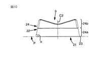
旋削インサート9の設計については、図5〜21の異なる他の実施形態において、より詳細に説明する。異なる実施形態において、旋削インサート9に対する共通点は、旋削インサート9が前面21と、包絡面22と、前面21が包絡面22と交差する円形の切れ刃23と有する点である。したがって、切れ刃23は前面21の回りを延び、包絡面22に対して角度αを形成する平面P内に位置する。全ての実施形態において、前面21は平面であり、平面Pと共通する。しかしながら、前面21は他の形状、例えば凹形状、凸形状とすることもできる。
The design of the turning
包絡面22は、切り屑面24を形成し、金属切削加工で生成した切り屑に当たるように配置されている。切り屑面24は切り屑破断手段を備える。切り屑面24は、切れ刃23に隣接する円周状の第1の部分24aと、この円周状の第1の部分24aに隣接する円周状の第2の部分とを備える。
The envelope surface 22 forms a
図1及び図2において、工作機械は第1の機械据え付け位置に配置され、被削材3の回転対称な外周面が旋削によって加工される。外周面は円柱状であるが、円錐状又は凸形状や凹形状であってもよい。旋削インサート9は、第2の駆動部材11からわかるように、反時計方向である回転方向rに向かって回転する。被削材3に係合する旋削インサート9の切れ刃23上の点は、図2に示すように、工具軸C2に平行である被削材3の中心面内又は中心面のそばにある。平面P内にある被削材3の回転方向Rは、工具軸C2に対して一定の角度をなす。この角度は80゜〜100゜である。回転方向Rに対する第2の駆動部材11からわかるように、旋削インサート9の回転方向rが時計方向になることに留意されたい。
1 and 2, the machine tool is arranged at the first machine installation position, and the rotationally symmetrical outer peripheral surface of the work material 3 is machined by turning. The outer peripheral surface is cylindrical, but may be conical, convex, or concave. As can be seen from the
図3及び4において、工作機械は第2の機械据え付け位置に配置され、被削材3の端面が加工される。例示では、端面旋削が示されている。端面は全体が平面形状ではなく、例えば凹形状又は凸形状である。被削材3の回転方向Rは、第1の駆動部材4から分かるように時計方向である。例において、旋削インサートの回転方向Rは、第2の駆動部材11から分かるように反時計方向である。示される工作機械において、被削材軸C1と工具軸C2とは、約1゜から10゜、好ましくは5゜又は−1゜から−10゜、より好ましくは−5゜の角度をなす。
3 and 4, the machine tool is disposed at the second machine installation position, and the end surface of the work material 3 is machined. In the illustration, end face turning is shown. The entire end surface is not a planar shape, for example, a concave shape or a convex shape. The rotation direction R of the work material 3 is clockwise as can be seen from the
図5〜8は、旋削インサート9の第4の実施形態を示す。旋削インサート9は、工具ホルダ10に旋削インサート9を締結するために、図20に示すネジ38のような締結要素を受け入れるための締結孔25を有する切削インサートとして形成されている。締結孔25は、前面21と旋削インサート9を貫通して延びている。
5 to 8 show a fourth embodiment of the turning
切り屑面24の第1の部分24aは、回転対称の第1の延長部分を有し、第1の実施形態では、図7及び8に示すように、工具C2を備える断面において凹形状を有している。第1の実施形態において、角度αは切れ刃23の近傍で測定され、第1の部分24aに関して90度より小さい角度である。角度αは40゜〜80゜である。
The
切り屑破断手段は、切り屑面24の円周状の第2の部分24bにより構成されている。第1の実施形態では、第2の部分24bは、切り屑破断手段の少なくとも一部を形成する非回転対称の第2の延長部分を有する。切り屑破断手段は、工具C2に関して外側に延びる少なくとも一つの段部26、及び/又は工具C2に関して内側に延びる凹部を備える。第1の実施形態において、このような形状は、工具軸C2に関して外側に延び、工具軸C2に対して垂直な部分で示すように、第2の部分の多角形状を形成する、4つの段部26を備える切り屑破断手段によって具体化されている。多角形状は、工具軸C2に関して外側に延びるコーナ領域、又は羽根を備える。第1の実施形態では、多角形状が四角又は本質的に四角である。
The chip breaking means is constituted by a circumferential
工具軸C2に関して外側に延びている段部26は限定面27を備え、限定面27が第2の部分24bの包絡面24bに交差する切れ刃28を形成する。
The
図9〜12は、旋削インサート9の第2の実施形態を示す。第2の実施形態の旋削インサート9は、図10〜12に示すように、第1の部分24aが円錐形状であるという点において、第1の実施形態の旋削インサートとは異なる。したがって、角度αは第1の部分24aに関して90゜より小さい。第1の部分は円柱状であるということに留意すべきできであり、角度αは、第1の部分24aに関して90゜に等しいか、又は本質的に90゜である。
9 to 12 show a second embodiment of the turning
図13〜15は、旋削インサート9の第3の実施形態を示す。この実施形態における旋削インサート9は、切り屑破断手段が複数の凹部31を備え、これらの凹部がファセット、チャンファ部として、第2の部分24bの包絡面22に具体化されている点において、第1の実施形態による旋削インサートとは異なる。これらのファセットは平面又は凹面とすることができる。第3の実施形態において、12個の凹部31が示されている。凹部31の数は変更可能であり、例えば、3,4,5,6又はそれ以上、又は12個以上であり、少なくとも部分的に旋削インサート9の直径に依存する。
13 to 15 show a third embodiment of the turning
図16〜19は、切り屑破断手段が3個の段部26を備え、多角形状、すなわち、工具軸C2に垂直な部分で示すように、三角形状をなすという点において、第2の実施形態とは異なる。第1の部分24aは、円錐形状であるが、円柱形状をなすこともでき、工具軸C2を有する断面において、凹形状をなすこともできる。
16 to 19 show a second embodiment in that the chip breaking means includes three
第4の実施形態は、前の実施形態とは異なり、旋削インサート9が、工具ホルダ10の対応する開口34に挿入されて締結されるテーパ状の締結ピン33を有する。図19に示されるように、締結ピン33と開口34はねじであり、旋削インサート9が工具ホルダ10に固定されたとき、互いに係合する。
Unlike the previous embodiment, the fourth embodiment has a tapered
図20は、第1の実施形態による工具ホルダと旋削インサート9とを有する工具8を示す。旋削インサート9は、固定ねじ38によって工具ホルダ10に取り外し可能に装着される。
FIG. 20 shows a
図21及び22は、旋削インサート9の第5の実施形態を示す。切り屑破断手段は、工具軸C2に関して内側に延びる円周ノッチ35と、工具軸C2に関して外側に延びる円周段部36とを備える。このような切り屑破断手段の回転対称形状は、第2の部分24b、すなわち、切れ刃23から一定の距離に設けることが好ましい。第5の実施形態における切り屑破断手段は、円周ノッチ35と円周段部36の両方を備えることは必ずしも必要ではないことに留意されたい。切り屑破断手段は、円周ノッチ35又は円周段部36として形成できる。
21 and 22 show a fifth embodiment of the turning
図23〜26は、第6の実施形態による旋削インサート9を示し、工具8に装着された工具部品8’の一体部品である。旋削インサート9は、例えば、切れ刃23を作るために工具部品8’を加工することによって、工具部品8’に形成されている。工具部品8’は、二つの端部を有する円柱体として形成されている。一つ又は二つの端部は旋削インサート9と一体的である。図示する実施において、工具部品8’は、無垢又は本質的に無垢体として形成されている。しかしながら、工具部品8’は、無垢体を貫通して延びる一つ以上の冷却孔(図示せず)を備えることもできる。
23 to 26 show the turning
第6の実施形態において、工具8は工具ホルダ10を有する。工具ホルダはチャック状ホルダ又は工具チャックとして形成されている。工具ホルダ10は、円柱形状、又は本質的には円柱形状のキャビティを備えている。キャビティは、旋削インサート9がキャビティの外側に位置するようにして、旋削インサート9を含む工具部品8’を受け入れる。第6の実施形態における工具ホルダ10は、一つ以上のクランプジョー(図示しない)。クランプジョーは、キャビティ内で工具部品8’を保持するために、工具部品8’に対して半径方向に作用することが好ましい。
In the sixth embodiment, the
工具部品8’は、超硬合金で作ることができ、または一つ又は二つの端部において超硬合金より硬い材料で作ることもできる。この材料は、層又は結合した一片として旋削インサート9に適用され、複数の異なる材料、例えば、セラミック、立方晶窒化硼素CBN、多結晶ダイヤモンドPCDなどを備えることができる。
The tool part 8 'can be made of cemented carbide or can be made of a material harder than cemented carbide at one or two ends. This material is applied to the
旋削インサート9を形成する工具部品8’の部分は、他の実施形態の旋削インサート9として形成されることができる。したがって、前面21と、包絡面22と、前面21と包絡面22とが交差する部分に配置された円形状の切れ刃23を備える。切れ刃23は、前面21の回りを延び、包絡面22に対して角度α(図23〜25には示されていない)を形成する平面P内に位置する。したがって、包絡面22は切り屑面を形成し、金属切削加工中に生成した切り屑と当たるように配置されている。切り屑面は、切れ刃23に隣接する円周状の第1の部分24aと、第1の部分24aに隣接する円周状の第2の部分24bを備える。切り屑破断手段は、第2の部分24bによって構成されている。第1の部分24aは、回転対称の第1の延長部分を有する。図示する実施形態において、角度αは第1の部分に24aに関して90゜より小さい。第1の部分24aは、円錐形状、又は工具軸C2を含む断面に示すように、凹形状である。第2の部分24bは、切り屑破断手段を形成する非回転対称の第2の延長部分を有する。
The part of the
第6の実施形態によると、図13〜15に示す第3の実施形態のように、切り屑破断手段は工具軸C2に関して内側に延びる複数の凹部31を備え、第2の部分24bの包絡面22において、平面、又はファセット、又はチャンファとして具体化される。
According to the sixth embodiment, as in the third embodiment shown in FIGS. 13 to 15, the chip breaking means includes a plurality of
第1及び第3の実施形態において、第1の部分24aの凹形状は、切り屑破断手段の少なくとも一部分を形成する。切り屑破断は、凹形状の曲率半径が相対的に小さいときに行われ、すなわち、切り屑は細かく破断される。第1の部分24aの凹形状は、第2の部分24bの切り屑破断手段と組み合わされる。
In the first and third embodiments, the concave shape of the
もし曲率半径が十分に短いならば、第1の部分の凹形状が旋削インサート9の切り屑破断手段となり、第2の部分24bは切り屑破断手段を備えない。第2の部分24bは、回転対称な第2の延長部分となる。
If the radius of curvature is sufficiently short, the concave shape of the first part becomes the chip breaking means of the turning
したがって、示された旋削インサートを有する示された工作機械によって、効率的な旋削加工が実施され、切り屑面を形成する包絡面は、生成した切り屑を短い長さに効率的に破断する手段を有する。制御装置5と異なる駆動手段によって、異なる加工パラメータが影響を受ける。例えば、第1及び第2の駆動部材が、金属加工の異なる特性を実現するために所望の回転速度に調整される。
Thus, an efficient turning operation is performed by the indicated machine tool with the indicated turning insert, and the enveloping surface forming the chip surface is a means to efficiently break the generated chips to a short length Have Different machining parameters are affected by the driving means different from the
好適には、第1及び第2の駆動部材は、被削材3の第1の回転速度が旋削インサート9の第2の回転速度より高くなるように制御される。工具軸回りの旋削インサート9の回転速度は、1分当たり数回転から3000r/minまで、例えば、約200,500,1000,1500,2000又は2500r/minとすることができる。加工中における第2の回転速度は変更可能である。更に、旋削インサート9は、高摩擦と高熱をもたらす被削材3に対して相対的に高い回転速度を与えられ、切り屑生成において被削材を局部的に溶かす。旋削インサート9は、相対的に低い回転速度を与えられ。非回転対称形状の手段との組み合わせにより、効率的な切り屑破断をもたらす。
Preferably, the first and second drive members are controlled such that the first rotational speed of the work material 3 is higher than the second rotational speed of the turning
本発明は、示された実施形態に制限されないが、後述する請求項の範囲内において修正、変更が可能である。 The present invention is not limited to the embodiments shown, but can be modified and changed within the scope of the following claims.
超硬合金を除く旋削インサート9は、複数の異なるタイプの材料、例えば、セラミックス、立方晶窒化硼素、多結晶ダイヤモンドなどから作ることができる。また、旋削インサート9は、異なる被覆を備えることもできる。
The turning
一般に、本発明による旋削インサート9を含む示された工具8は、0.01〜2.0mm、適切には0.05〜0.8mmの間の切り込みで使用される。最大の切り込みは、旋削インサート9の直径に関係する。
In general, the illustrated
20mmの直径を有する旋削インサート9の最大切り込みは、20mm、すなわち、10対1の比となる。典型的には、旋削インサート9は6〜32mmの間の直径を有する。
The maximum cut of the turning
1 被削材スピンドル
2 保持部材
3 被削材
4 第1の駆動部材
5 制御装置
8 工具
9 工具部品
10 工具ホルダ
11 第2の駆動部材
12 工具スピンドル
14 締結ピン
21 前面
22 包絡面
23 切れ刃
24 切り屑面
24a 円周の第1の部分
24b 円周の第2の部分
26 段部
27 限定面
31 凹部
35 円周ノッチ
36 円周段部
38 固定ねじ
C1 被削材軸
C2 工具軸
DESCRIPTION OF
Claims (17)
前面(21)と、
包絡面(22)と、
前面(21)と包絡面(22)とが交差する位置に配置された円周状の切れ刃(23)であって、切れ刃(23)が前面(21)の回りを延びると共に包絡面(22)に対して角度αをなす平面(P)内に位置し、工具軸(C2)が平面(P)に対して垂直方向で旋削インサート(9)を通って延びる、切れ刃(23)とを備え、
切削加工中に、第2の回転速度で工具軸(C2)の回りを回転する旋削インサート(9)において、
包絡面(22)が、切り屑面(24)を形成すると共に切削加工で生成された切り屑が当たるように配置され、切り屑面(24)が切り屑破断手段を備え、
前記切り屑面が、切れ刃(23)に隣接する円周状の第1の部分(24a)と、第1の部分(24a)に隣接する第2の部分(24b)と、を備え、
前記切り屑破断手段が、前記第2の部分(24b)に形成され、工具軸(C2)に対して内側に延びる複数の凹部(31)を備える、
ことを特徴とする旋削インサート(9)。 A turning insert (9) for cutting a work material rotating in a rotation direction R at a first rotation speed around a work material axis (C1),
The front surface (21);
An envelope surface (22);
A circumferential cutting edge (23) disposed at a position where the front surface (21) and the envelope surface (22) intersect with each other, the cutting blade (23) extending around the front surface (21) and the envelope surface ( 22) a cutting edge (23), which lies in a plane (P) that forms an angle α with respect to 22) and whose tool axis (C2) extends through the turning insert (9) in a direction perpendicular to the plane (P). With
In the turning insert (9) rotating around the tool axis (C2) at the second rotational speed during cutting,
The envelope surface (22) forms a chip surface (24) and is disposed so that the chip generated by the cutting process is hit, the chip surface (24) includes a chip breaking means,
The chip surface comprises a circumferential first portion (24a) adjacent to the cutting edge (23) and a second portion (24b) adjacent to the first portion (24a),
The cutting chip breaking means is formed on said second portion (24 b), provided with a plurality of recesses (31) extending inwardly relative to the tool axis (C2),
Turning insert (9) characterized in that.
旋削インサート(9)が、
前面(21)と、
包絡面(22)と、
前面(21)と包絡面(22)とが交差する位置に配置された円周状の切れ刃(23)であって、切れ刃(23)が前面(21)の回りを延びると共に包絡面(22)に対して角度αをなす平面(P)内に位置し、工具軸(C2)が平面(P)に対して垂直方向で旋削インサート(9)を通って延びる、切れ刃(23)とを備え、
旋削インサート(9)が、切削加工中に、第2の回転速度で工具軸(C2)の回りを回転する工具部品(8’)において、
包絡面(22)が、切り屑面(24)を形成すると共に切削加工で生成された切り屑が当たるように配置され、切り屑面(24)が切り屑破断手段を備え、
前記切り屑面が、切れ刃(23)に隣接する円周状の第1の部分(24a)と、第1の部分(24a)に隣接する第2の部分(24b)と、を備え、
前記切り屑破断手段が、前記第2の部分(24b)に形成され、工具軸(C2)に対して内側に延びる複数の凹部(31)を備える、
ことを特徴とする工具部品(8’)。 At least one turning insert integrally formed as a tool part (8 ') for cutting a work material that rotates around a work material axis (C1) in a rotation direction R at a first rotational speed. A tool part (8 ′) comprising (9),
Turning insert (9)
The front surface (21);
An envelope surface (22);
A circumferential cutting edge (23) disposed at a position where the front surface (21) and the envelope surface (22) intersect with each other, the cutting blade (23) extending around the front surface (21) and the envelope surface ( 22) a cutting edge (23), which lies in a plane (P) that forms an angle α with respect to 22) and whose tool axis (C2) extends through the turning insert (9) in a direction perpendicular to the plane (P). With
In the tool part (8 ′) in which the turning insert (9) rotates around the tool axis (C2) at a second rotational speed during the cutting process,
The envelope surface (22) forms a chip surface (24) and is disposed so that the chip generated by the cutting process is hit, the chip surface (24) includes a chip breaking means,
The chip surface comprises a circumferential first portion (24a) adjacent to the cutting edge (23) and a second portion (24b) adjacent to the first portion (24a),
The cutting chip breaking means is formed on said second portion (24 b), provided with a plurality of recesses (31) extending inwardly relative to the tool axis (C2),
A tool part (8 ') characterized in that.
旋削インサート(9)が、
前面(21)と、
包絡面(22)と、
前面(21)と包絡面(22)とが交差する位置に配置された円周状の切れ刃(23)であって、切れ刃(23)が前面(21)の回りを延びると共に包絡面(22)に対して角度αをなす平面(P)内に位置し、工具軸(C2)が平面(P)に対して垂直方向で旋削インサート(9)を通って延びる、切れ刃(23)とを備え、
前記包絡面(22)が、切り屑面(24)を形成すると共に切削加工で生成された切り屑が当たるように配置され、前記切り屑面(24)が切り屑破断手段を備え、
前記切り屑面が、切れ刃(23)に隣接する円周状の第1の部分(24a)と、第1の部分(24a)に隣接する第2の部分(24b)と、を備え、
前記切り屑破断手段が、前記円周状の第2の部分(24b)に形成され、工具軸(C2)に対して内側に延びる複数の凹部(31)を備え、
第1の回転速度で被削材軸(C1)の回りを回転方向(R)に、被削材(3)を有する被削材スピンドル(1)を回転するステップと、
第2の回転速度で工具軸(C2)の回りにおいて、工具(8)及び旋削インサート(9)を回転するステップと、
回転する旋削インサート(9)を回転する被削材(3)に係合させ、被削材(3)に対して旋削インサート(9)を送るステップと、を備えた金属切削加工方法において、
包絡面(22)が切り屑面(24)を形成すると共に切削加工で生成された切り屑に当たり、切り屑が切り屑面(24)の切り屑破断手段によって破断されるように、被削材(3)に対して旋削インサート(9)に送りを与える、ことを特徴とする金属切削加工方法。 A metal cutting method using a tool (8) provided with a turning insert (9),
Turning insert (9)
The front surface (21);
An envelope surface (22);
A circumferential cutting edge (23) disposed at a position where the front surface (21) and the envelope surface (22) intersect with each other, the cutting blade (23) extending around the front surface (21) and the envelope surface ( 22) a cutting edge (23), which lies in a plane (P) that forms an angle α with respect to 22) and whose tool axis (C2) extends through the turning insert (9) in a direction perpendicular to the plane (P). With
The envelope surface (22) forms a chip surface (24) and is disposed so as to hit a chip generated by cutting, and the chip surface (24) includes a chip breaking means,
The chip surface comprises a circumferential first portion (24a) adjacent to the cutting edge (23) and a second portion (24b) adjacent to the first portion (24a),
The cutting chip breaking means are formed on the circumferential second portion (24 b), provided with a plurality of recesses (31) extending inwardly relative to the tool axis (C2),
Rotating a work piece spindle (1) having a work piece (3) around a work piece axis (C1) in a rotation direction (R) at a first rotation speed;
Rotating the tool (8) and the turning insert (9) about the tool axis (C2) at a second rotational speed;
Engaging the rotating turning insert (9) with the rotating work material (3) and feeding the turning insert (9) to the work material (3),
Work material so that the envelope surface (22) forms the chip surface (24) and hits the chips generated by the cutting process, and the chips are broken by the chip breaking means of the chip surface (24). A metal cutting method characterized by feeding a turning insert (9) to (3).
被削材(3)を保持するための保持部材(2)を有する被削材スピンドル(1)と、
第1の回転速度で被削材軸(C1)の回りを回転方向(R)に被削材スピンドル(1)及び被削材(3)を回転する第1の駆動部材(4)と、
旋削インサート(9)を有する工具であって、
旋削インサート(9)が、
前面(21)と、
包絡面(22)と、
前面(21)と包絡面(22)とが交差する位置に配置された円周状の切れ刃(2 3)であって、切れ刃(23)が前面(21)の回りを延びると共に包絡面(22) に対して角度αをなす平面(P)に位置し、工具軸(C2)が平面(P)に対して垂 直方向で旋削インサート(9)を通って延びる、切れ刃(23)とを備える、工具と 、
第2の回転速度で工具軸(C2)の回りで工具(8)及び旋削インサート(9)を回転するために配置された第2の駆動部材(11)と、
回転する旋削インサート(9)を回転する被削材(3)に係合するように配置させ、被削材(3)に対して旋削インサート(9)に送りを与える送り装置と、を備えた機械において、
包絡面(22)が、切り屑面(24)を形成すると共に切削加工で生成された切り屑が当たるように配置され、切り屑面(24)が切り屑破断手段を備え、
前記切り屑面が、切れ刃(23)に隣接する円周状の第1の部分(24a)と、第1の部分(24a)に隣接する第2の部分(24b)と、を備え、
前記切り屑破断手段が、前記第2の部分(24b)に形成され、工具軸(C2)に対して内側に延びる複数の凹部(31)を備える、
ことを特徴とする工作機械。 A machine tool for cutting,
A workpiece spindle (1) having a holding member (2) for holding the workpiece (3);
A first drive member (4) for rotating the work piece spindle (1) and the work piece (3) around the work piece axis (C1) in the rotation direction (R) at a first rotation speed;
A tool with a turning insert (9),
Turning insert (9)
The front surface (21);
An envelope surface (22);
A circumferential cutting edge (23) arranged at a position where the front surface (21) and the envelope surface (22) intersect, the cutting blade (23) extending around the front surface (21) and the envelope surface Cutting edge (23), which lies in a plane (P) that makes an angle α with respect to (22) and whose tool axis (C2) extends through the turning insert (9) in a direction perpendicular to the plane (P) A tool comprising, and
A second drive member (11) arranged to rotate the tool (8) and the turning insert (9) about the tool axis (C2) at a second rotational speed;
A rotating device (9) arranged to engage with the rotating work material (3), and a feed device for feeding the turning insert (9) to the work material (3). In the machine
The envelope surface (22) forms a chip surface (24) and is disposed so that the chip generated by the cutting process is hit, the chip surface (24) includes a chip breaking means,
The chip surface comprises a circumferential first portion (24a) adjacent to the cutting edge (23) and a second portion (24b) adjacent to the first portion (24a),
The cutting chip breaking means is formed on said second portion (24 b), provided with a plurality of recesses (31) extending inwardly relative to the tool axis (C2),
A machine tool characterized by that.
Applications Claiming Priority (2)
| Application Number | Priority Date | Filing Date | Title |
|---|---|---|---|
| SE1050140-1 | 2010-02-12 | ||
| SE1050140A SE534651C2 (en) | 2010-02-12 | 2010-02-12 | Cutting, tool part, procedure and machine tool for chip cutting metal machining |
Publications (2)
| Publication Number | Publication Date |
|---|---|
| JP2011161628A JP2011161628A (en) | 2011-08-25 |
| JP5941618B2 true JP5941618B2 (en) | 2016-06-29 |
Family
ID=43903996
Family Applications (1)
| Application Number | Title | Priority Date | Filing Date |
|---|---|---|---|
| JP2011026850A Expired - Fee Related JP5941618B2 (en) | 2010-02-12 | 2011-02-10 | Turning insert, tool part, metal cutting method and machine tool |
Country Status (6)
| Country | Link |
|---|---|
| US (1) | US8776649B2 (en) |
| EP (1) | EP2359965B1 (en) |
| JP (1) | JP5941618B2 (en) |
| KR (1) | KR101689895B1 (en) |
| CN (1) | CN102161108B (en) |
| SE (1) | SE534651C2 (en) |
Families Citing this family (13)
| Publication number | Priority date | Publication date | Assignee | Title |
|---|---|---|---|---|
| AT512452A1 (en) * | 2012-02-01 | 2013-08-15 | Boehlerit Gmbh & Co Kg | CUTTING BOARD |
| JP6379623B2 (en) * | 2013-05-13 | 2018-08-29 | 株式会社ジェイテクト | Cutting apparatus and cutting method |
| JP6669983B2 (en) | 2014-06-27 | 2020-03-18 | 株式会社ジェイテクト | Cutting device and cutting method |
| US10654113B2 (en) * | 2017-01-20 | 2020-05-19 | Jtekt Corporation | Cutting method and cutting apparatus |
| JP7035464B2 (en) * | 2017-01-20 | 2022-03-15 | 株式会社ジェイテクト | Cutting method and cutting equipment |
| KR102328378B1 (en) * | 2017-04-25 | 2021-11-22 | 두산공작기계 주식회사 | Machine tool |
| DE102017120188A1 (en) * | 2017-09-01 | 2019-03-07 | Kennametal Inc. | Tangential cutting insert, cutting tool with a Tangentialschneidsatz and method for producing a Tangentialschneideinsatzes |
| EP3536427B1 (en) * | 2018-03-08 | 2022-08-17 | AB Sandvik Coromant | Turning tool and turning method for cnc-machines |
| US20210046551A1 (en) * | 2018-03-08 | 2021-02-18 | Ab Sandvik Coromant | Turning method for a cnc-lathe and a turning tool |
| US20200001374A1 (en) * | 2018-06-29 | 2020-01-02 | Herramientas Preziss, S.L. | Cutting Insert Applicable To Machining Tools And The Tool Bearing It |
| CN109482902A (en) * | 2018-12-13 | 2019-03-19 | 嘉兴市台嘉机械有限公司 | A kind of broken cutting apparatus |
| CN110883343B (en) * | 2019-11-25 | 2021-05-11 | 上海电气电站设备有限公司 | Method for processing multistage blades of steam turbine generator |
| JP2022092449A (en) * | 2020-12-10 | 2022-06-22 | オークマ株式会社 | Workpiece turning and machining method and machine tool |
Family Cites Families (18)
| Publication number | Priority date | Publication date | Assignee | Title |
|---|---|---|---|---|
| GB320809A (en) * | 1928-12-05 | 1929-10-24 | Cammell Laird & Co Ltd | Improvements in or relating to turning and boring tools |
| JPS582004B2 (en) * | 1979-12-27 | 1983-01-13 | カリニングラドスキ− テクニチエスキ− インスチテユ−ト リブノイ プロミシユレンノスチ イ ホズヤイストヴア | rotary cutting device |
| JPS57114301A (en) * | 1980-12-26 | 1982-07-16 | Kaliningr Tekhn I Ribunoi Puro | Method of mechanically working workpiece by edge type rotary cutting tool |
| JPS59214502A (en) * | 1983-04-04 | 1984-12-04 | ゼネラル・エレクトリツク・カンパニイ | Insert for metal cutting bite |
| JPS6112612U (en) * | 1984-06-28 | 1986-01-24 | 住友電気工業株式会社 | circular throw-away tip |
| US4812087A (en) * | 1987-07-09 | 1989-03-14 | Gte Valenite Corporation | End mill cutting tool and indexable insert therefor |
| EP0719193B1 (en) * | 1993-09-13 | 1998-10-28 | Widia GmbH | Cutting insert |
| US5520444A (en) * | 1995-02-27 | 1996-05-28 | Champion Equipment Co. | Method of cutting and cutting rotative bit |
| SE506679C2 (en) * | 1995-06-21 | 1998-01-26 | Seco Tools Ab | Cutting tools, preferably for milling |
| IL119841A (en) * | 1996-12-16 | 2000-02-29 | Iscar Ltd | Cutting inserts |
| IL123685A (en) * | 1998-03-16 | 2001-09-13 | Iscar Ltd | Modular cutting tool assembly |
| SE525913C2 (en) * | 2002-12-20 | 2005-05-24 | Seco Tools Ab | Cutter, tool and method of mounting the insert where the insert can be oriented in the desired position |
| US7156006B2 (en) * | 2003-09-02 | 2007-01-02 | Kennametal Inc. | Method and assembly for rotating a cutting insert during a turning operation and inserts used therein |
| US8573901B2 (en) * | 2003-09-02 | 2013-11-05 | Kennametal Inc. | Assembly for rotating a cutting insert during a turning operation and inserts used therein |
| JP2005233098A (en) | 2004-02-20 | 2005-09-02 | Yamaha Motor Co Ltd | Suction device for vehicle |
| US7325471B2 (en) | 2004-09-07 | 2008-02-05 | Kennametal Inc. | Toolholder and cutting insert for a toolholder assembly |
| JP4231496B2 (en) * | 2005-08-01 | 2009-02-25 | 住友電工ハードメタル株式会社 | Throwaway tip |
| SE533484C2 (en) * | 2009-02-20 | 2010-10-05 | Sandvik Intellectual Property | Rotary tool for chip separating machining and cutting for this |
-
2010
- 2010-02-12 SE SE1050140A patent/SE534651C2/en not_active IP Right Cessation
-
2011
- 2011-01-25 EP EP11152027.6A patent/EP2359965B1/en active Active
- 2011-02-10 JP JP2011026850A patent/JP5941618B2/en not_active Expired - Fee Related
- 2011-02-11 KR KR1020110012180A patent/KR101689895B1/en active IP Right Grant
- 2011-02-11 US US13/025,915 patent/US8776649B2/en not_active Expired - Fee Related
- 2011-02-14 CN CN201110039511.0A patent/CN102161108B/en not_active Expired - Fee Related
Also Published As
| Publication number | Publication date |
|---|---|
| EP2359965B1 (en) | 2019-11-06 |
| US8776649B2 (en) | 2014-07-15 |
| KR101689895B1 (en) | 2016-12-26 |
| EP2359965A1 (en) | 2011-08-24 |
| CN102161108A (en) | 2011-08-24 |
| JP2011161628A (en) | 2011-08-25 |
| US20110197723A1 (en) | 2011-08-18 |
| CN102161108B (en) | 2015-11-25 |
| SE534651C2 (en) | 2011-11-08 |
| KR20110093713A (en) | 2011-08-18 |
| SE1050140A1 (en) | 2011-08-13 |
Similar Documents
| Publication | Publication Date | Title |
|---|---|---|
| JP5941618B2 (en) | Turning insert, tool part, metal cutting method and machine tool | |
| RU2350436C2 (en) | Ceramic drill for high-speed drilling | |
| EP3009215B1 (en) | Chamfering cutter comprising a disposable chamfering blade | |
| US9707650B2 (en) | System and method for machining a workpiece | |
| JP2008114308A (en) | Rotary cutting tool | |
| JP6287592B2 (en) | Small diameter end mill | |
| JP6432989B2 (en) | Chamfering cutter with helical pointed blade and discharge groove | |
| JP2003053620A (en) | Cutting bit and milling tool for milling operation | |
| JP5914446B2 (en) | Cutting tool and workpiece machining method using the same | |
| JP5776595B2 (en) | End mill with coolant hole | |
| KR20190045371A (en) | Cutting inserts and cutting blades | |
| JP2015196203A (en) | Edge replaceable metal saw | |
| JP5953173B2 (en) | Cutting tools | |
| JP2010046733A (en) | Thread milling cutter | |
| KR20130117989A (en) | Cutting tip | |
| JP2004160581A (en) | Manufacturing method for diamond coated tool, and diamond coated tool | |
| JP2016155178A (en) | Rotary tool and manufacturing method thereof | |
| JP5939687B2 (en) | Cutting tools | |
| JP5560748B2 (en) | Exchangeable grooving tool and peripheral grooving method | |
| JP4623674B2 (en) | Rotary cutting tool | |
| JP4644568B2 (en) | Drill | |
| JP2009136980A (en) | Cutting tool | |
| JP5471539B2 (en) | Replaceable cutting edge grooving tool and end face grooving method | |
| JP2905202B2 (en) | Drill | |
| JP2008254130A (en) | Hole saw and its manufacturing method |
Legal Events
| Date | Code | Title | Description |
|---|---|---|---|
| A621 | Written request for application examination |
Free format text: JAPANESE INTERMEDIATE CODE: A621 Effective date: 20110613 |
|
| A621 | Written request for application examination |
Free format text: JAPANESE INTERMEDIATE CODE: A621 Effective date: 20131210 |
|
| A131 | Notification of reasons for refusal |
Free format text: JAPANESE INTERMEDIATE CODE: A131 Effective date: 20141007 |
|
| A601 | Written request for extension of time |
Free format text: JAPANESE INTERMEDIATE CODE: A601 Effective date: 20150106 |
|
| A521 | Written amendment |
Free format text: JAPANESE INTERMEDIATE CODE: A523 Effective date: 20150407 |
|
| A131 | Notification of reasons for refusal |
Free format text: JAPANESE INTERMEDIATE CODE: A131 Effective date: 20151006 |
|
| A601 | Written request for extension of time |
Free format text: JAPANESE INTERMEDIATE CODE: A601 Effective date: 20160105 |
|
| A521 | Written amendment |
Free format text: JAPANESE INTERMEDIATE CODE: A523 Effective date: 20160406 |
|
| TRDD | Decision of grant or rejection written | ||
| A01 | Written decision to grant a patent or to grant a registration (utility model) |
Free format text: JAPANESE INTERMEDIATE CODE: A01 Effective date: 20160510 |
|
| A61 | First payment of annual fees (during grant procedure) |
Free format text: JAPANESE INTERMEDIATE CODE: A61 Effective date: 20160523 |
|
| R150 | Certificate of patent or registration of utility model |
Ref document number: 5941618 Country of ref document: JP Free format text: JAPANESE INTERMEDIATE CODE: R150 |
|
| RD02 | Notification of acceptance of power of attorney |
Free format text: JAPANESE INTERMEDIATE CODE: A7422 Effective date: 20160606 |
|
| RD02 | Notification of acceptance of power of attorney |
Free format text: JAPANESE INTERMEDIATE CODE: R3D02 |
|
| R250 | Receipt of annual fees |
Free format text: JAPANESE INTERMEDIATE CODE: R250 |
|
| LAPS | Cancellation because of no payment of annual fees |