JP5941430B2 - Method for producing porous glass preform for optical fiber - Google Patents
Method for producing porous glass preform for optical fiber Download PDFInfo
- Publication number
- JP5941430B2 JP5941430B2 JP2013081158A JP2013081158A JP5941430B2 JP 5941430 B2 JP5941430 B2 JP 5941430B2 JP 2013081158 A JP2013081158 A JP 2013081158A JP 2013081158 A JP2013081158 A JP 2013081158A JP 5941430 B2 JP5941430 B2 JP 5941430B2
- Authority
- JP
- Japan
- Prior art keywords
- base material
- hole
- glass
- porous
- preform
- Prior art date
- Legal status (The legal status is an assumption and is not a legal conclusion. Google has not performed a legal analysis and makes no representation as to the accuracy of the status listed.)
- Active
Links
Images


Description
本発明は、貫通孔を有する光ファイバ用多孔質母材の透明ガラス化方法およびそれを用いた光ファイバ用透明ガラス母材に関する。 The present invention relates to a transparent vitrification method for a porous preform for optical fibers having through holes, and a transparent glass preform for optical fibers using the same.
光ファイバの技術進歩に伴い、特殊な構造を有する光ファイバが実現されるようになって来た(特許文献1〜11参照)。上記特殊な構造を有する光ファイバとして図21に示すものがある。同図(a)の空孔アシストファイバ、同図(b)のフォトニック結晶型ファイバ、同図(c)のマルチコアファイバ、そして同図(d)のパンダファイバ(PANDA(Polarization-maintaining AND Absorption-reducing)ファイバ)である。これらの光ファイバは、光ファイバ母材を製造する工程が他の一般的な光ファイバに比して複雑で非常に手間とコストのかかる複数の加工処理工程から成る。
With the technical progress of optical fibers, optical fibers having a special structure have been realized (see
すなわち、上記空孔アシストファイバは次のように製造される。まず、図22に示すように、VAD法(気相軸付け法:Vapor phase Axial Deposition method)で石英ガラスの種棒101にコア102と、その外周を覆うクラッド103を形成することにより多孔質母材104が製造される。次いで図23に示すように、その多孔質母材104を高温電気炉105加熱された石英ガラス反応容器106内に矢印107で示す方向に所定速度で送り込み、同時に、上記石英ガラス反応容器106内に矢印108−1方向からHeガスと塩素ガスの混合ガスを流し込みながら矢印108−2方向に排気する。これにより、多孔質母材104が透明ガラス化され、図24に示すようなコア112の外周がクラッド113で覆われた、透明ガラス化された光ファイバ母材114(以下、透明ガラス母材114という)が得られる。
That is, the hole assist fiber is manufactured as follows. First, as shown in FIG. 22, a porous mother is formed by forming a
その後に、透明ガラス母材114内に貫通孔を開けるために、図25に示すように、上記透明ガラス母材114の上端と下端をガラス切断機で切断してフラットな上面115とフラットな下面116を形成する(図25(b))。その後に、上記透明ガラス母材114の透明化されたクラッド113内に、上記透明ガラス母材114の長手方向に延びる複数の貫通孔117をドリル、あるいは超音波で切削することにより開け(図25(c))、貫通孔付き光ファイバ母材114が製造される。この方法では、貫通孔を形成するのにドリルを用いて、あるいは超音波で切削するので、貫通孔を形成した後に洗浄、脱水、乾燥、加熱工程を必ず行わなければならない。上記工程を経た後に空孔アシストファイバ母材を完成させ、その後に該母材を線引きして空孔アシストファイバが得られる。
Thereafter, in order to open a through-hole in the transparent
図21(b)のフォトニック結晶型ファイバも空孔アシストファイバと同様の方法で製造される。まずは石英ガラスの種棒101にコア102と、その外周を覆うクラッド103を形成することにより多孔質母材104を製造する。次いでその多孔質母材104を図25に示した方法を用いて透明ガラス化した光ファイバ母材114を得る。その後、空孔アシストファイバ母材と同様に図21(a)〜図21(c)の方法を用いて空孔(貫通孔)117を有する光ファイバ母材114を得る。この方法でも貫通孔を形成した後に洗浄、脱水、乾燥、加熱工程を必ず行わなければならない。その後に該母材を線引きしてフォトニック結晶型ファイバを得る。フォトニック結晶型ファイバの別の製造方法として、複数本のガラス細管を束ねたものを線引きして一体化する方法も用いられている。
The photonic crystal type fiber of FIG. 21B is also manufactured by the same method as the hole assist fiber. First, a
図21(c)のマルチコアファイバでは、まず前記したVAD法でSiO2ロッドからなる多孔質母材が製造される。次いで、前記した方法でその多孔質母材を透明ガラス化し、その母材の上面と下面の切断によるフラット化を行なう。その後に、その母材に所定間隔をおいて長手方向に延びる複数の貫通孔117を、前記したように、ドリルを用いて、あるいは超音波で切削することによって形成してコア挿入用貫通孔を有する光ファイバ用ガラス母材(貫通孔付きガラス成形体)を製造する。その後に上記母材の洗浄、脱水、乾燥、加熱工程を経て上記貫通孔の中に別の工程で製造しておいたコア母材117−1〜117−7を挿入し、融着してマルチコアファイバ用母材とする。この母材を線引きしてマルチコアファイバが製造される。
In the multi-core fiber shown in FIG. 21 (c), a porous preform made of SiO 2 rod is first manufactured by the VAD method described above. Next, the porous base material is made into transparent glass by the above-described method, and flattening is performed by cutting the upper surface and the lower surface of the base material. Thereafter, a plurality of through-
非特許文献1によれば、図21(d)のパンダファイバも、前記方法と同様にVAD法でコアとクラッドを有する多孔質母材を製造し、その後に多孔質母材の透明ガラス化を行う。そして、その透明ガラス母材の上面と下面を切断してフラット化し、その後に、その母材のコア112を取り囲んだクラッド113内に所定間隔をおいて長手方向に延びる2つの貫通孔を、ドリルを用いて、あるいは超音波で切削することによって形成する。これにより、応力付与部となるガラスロッド挿入用貫通孔を有する光ファイバ用ガラス母材(貫通孔付きガラス成形体)が製造される。その後に光ファイバ用母材の洗浄、脱水、乾燥、加熱工程を経た後、上記貫通孔の中に別の工程で製造しておいたB2O3を添加したSiO2ガラスからなる応力付与部となるガラスロッド118−1、118−2を挿入し、高温加熱処理を施して上記母材とロッドを融着、一体化する。このようにして、目的とするパンダファイバ用母材が製造される。その後に上記パンダファイバ用母材を線引きしてパンダファイバが得られる。
According to
このように上記光ファイバはいずれも光ファイバ母材の製造工程の段階において複雑で非常に手間とコストのかかる複数の加工工程(多孔質母材の製造、その母材の透明ガラス化、母材の上面と下面の切断によるフラット化、ドリルを用いて、あるいは超音波で切削することによる貫通孔の形成、その後に上記母材の洗浄、脱水、乾燥、加熱工程、その後の母材の線引き工程)を経なければならない。特に透明ガラス化した光ファイバ母材に後工程で貫通孔を形成するので、上記貫通孔内に水分、不純物が必ず混入する。水分の除去にはHeガスと塩素ガスを長時間にわたって流しながら高温加熱して除去していかなければならないが、貫通孔内の水分の一部はガラス化しているコア内やクラッド内に拡散、浸透してOH基となっているため、光ファイバ母材の外に出にくく、光損失を増大させる原因になっていた。 Thus, all of the above optical fibers are complicated and very laborious and costly in the manufacturing process of the optical fiber preform (manufacture of porous preform, transparent vitrification of the preform, preform) Flattening by cutting the upper surface and lower surface of the metal, forming a through-hole by cutting with a drill or ultrasonically, then cleaning, dehydrating, drying, heating process of the base material, and subsequent drawing process of the base material ). In particular, since a through hole is formed in a transparent glass-made optical fiber preform in a later step, moisture and impurities are always mixed in the through hole. In order to remove moisture, it must be removed by heating at a high temperature while flowing He gas and chlorine gas over a long period of time, but part of the moisture in the through holes diffuses into the vitrified core and cladding, Since it has penetrated into OH groups, it has been difficult to get out of the optical fiber preform, causing an increase in optical loss.
また、透明ガラス母材内に設けるコアを挿入するための貫通孔、クラッド内の屈折率を下げるための貫通孔、フォトニック結晶構造を実現するための貫通孔、応力付与部となるガラスロッドを挿入するための貫通孔の内径は挿入するガラスロッドの外径よりもわずかに小さく加工しておかないと、高温加熱による前記ガラスロッドの収縮率よりも上記透明ガラス母材の収縮率の方が小さいために、貫通孔と挿入するガラスロッドとの間に隙間が発生し、散乱損失を誘引する。しかし、現実的には上記貫通孔やガラスロッドの寸法を高精度に制御して製造することが難しい。さらに、貫通孔の内面表面粗さが大きい、貫通孔の真円度、真直度が良くない、といった問題点もあり、貫通孔内にガラスロッドを密着性良く挿入、融着して低散乱損失の光ファイバを実現することが難しかった。 In addition, a through hole for inserting a core provided in the transparent glass base material, a through hole for lowering the refractive index in the cladding, a through hole for realizing a photonic crystal structure, and a glass rod serving as a stress applying portion Unless the inner diameter of the through hole for insertion is slightly smaller than the outer diameter of the glass rod to be inserted, the shrinkage rate of the transparent glass base material is higher than the shrinkage rate of the glass rod due to high temperature heating. Since it is small, a gap is generated between the through hole and the glass rod to be inserted, and scattering loss is induced. However, in reality, it is difficult to manufacture by controlling the dimensions of the through hole and the glass rod with high accuracy. In addition, there are also problems such as the inner surface roughness of the through hole being large, the roundness and straightness of the through hole being poor, and low scattering loss by inserting and fusing the glass rod into the through hole with good adhesion. It was difficult to realize the optical fiber.
また、長尺の光ファイバを実現するためにはできるだけ長い母材を用いることが望ましい。しかし、ドリルを用いて貫通孔を形成する従来の方法では、50cm以上の長尺の光ファイバ母材(第1の母材)の長手方向に複数の貫通孔を精密に機械的に開けること、それら貫通孔の内面を研磨することは難しい。これは、50cm以上の長さのドリルを寸法精度、真直度、真円度良く製造することは極めてが難しく、しかもドリルを回転させながら母材に貫通孔を開けて行くので、ドリルの長さが長くなるほど回転むらが生じ易く、該ドリルの真直度、真円度が悪いと貫通孔の寸法精度が極めて悪くなるからである。結局のところ、従来は母材の長さを短くして短いドリルで貫通孔を形成し、その代わりに母材の外径を大きくしていた。 In order to realize a long optical fiber, it is desirable to use a base material that is as long as possible. However, in the conventional method of forming a through hole using a drill, a plurality of through holes are precisely mechanically opened in the longitudinal direction of a long optical fiber base material (first base material) having a length of 50 cm or more, It is difficult to polish the inner surfaces of these through holes. This is because it is extremely difficult to manufacture a drill with a length of 50 cm or more with good dimensional accuracy, straightness and roundness, and the drill hole is drilled through the base material while rotating the drill. This is because as the length becomes longer, rotation unevenness is more likely to occur, and when the straightness and roundness of the drill are poor, the dimensional accuracy of the through hole becomes extremely poor. After all, conventionally, the length of the base material is shortened and a through hole is formed with a short drill, and the outer diameter of the base material is increased instead.
しかし、母材の外径を大きくすると、貫通孔を形成した後の光ファイバ母材の線引き工程で大口径の炉心管を備えた高温電気炉を用いる必要がある。このような高温電気炉を用いることは現状では難しく、結局は線引き前に光ファイバ母材を延伸して外径を細くする工程を経なければならなかった。また一本の光ファイバ母材で長尺の光ファイバを実現することも難しかった。さらに付け加えるならば、VAD法で製造した光ファイバ母材の端面は円錐形状をしているために、上記貫通孔を開ける際には母材の上面及び下面を切断し、研磨したフラットな面にしなければならない。この切断や研磨の作業には多くの時間がかかるため、製造コストが高くなっていた。しかも、母材の上面及び下面をフラットな面にしても貫通孔を高寸法精度でうまく開けることが難しかった。 However, when the outer diameter of the preform is increased, it is necessary to use a high-temperature electric furnace equipped with a large-diameter core tube in the drawing process of the optical fiber preform after forming the through hole. It is difficult to use such a high-temperature electric furnace under the present circumstances. Eventually, before drawing, the optical fiber preform must be stretched to reduce the outer diameter. It was also difficult to realize a long optical fiber with a single optical fiber preform. In addition, since the end face of the optical fiber preform manufactured by the VAD method has a conical shape, the upper and lower surfaces of the preform are cut into a polished flat surface when opening the through hole. There must be. Since this cutting and polishing work takes a lot of time, the manufacturing cost is high. Moreover, even if the upper surface and the lower surface of the base material are flat, it has been difficult to successfully open the through hole with high dimensional accuracy.
さらに、マルチコアファイバを製造するためには、光を伝搬させるための重要なコア母材を前記貫通孔に挿入しなければならない。また、パンダファイバを製造するためには、応力付与部となるガラスロッドを前記貫通孔に挿入しなければならない。
機械的に開けた複数の貫通孔内にコア母材やガラスロッドを挿入し、両者を密着させるためには、該貫通孔を真直度、真円度良く形成しておかなければならない。特に、長尺の光ファイバの場合は、長尺のコア母材及びガラスロッドを長尺の貫通孔に挿入しなければならず、貫通孔をより高真直度、より高真円度に形成する必要がある。また、機械的に開けた貫通孔の内面は表面荒れが大きく、水分や不純物が付着しているため、表面荒れを小さくし、水分や不純物を除去するために、貫通孔の内面の研磨工程、洗浄工程、脱水、加熱工程を入念に行なわなければならない。また、貫通孔内にコア母材、あるいはガラスロッドを挿入した後に、貫通孔と当該コア母材、あるいは貫通孔とガラスロッドの間の隙間を無くして中実な光ファイバ母材にするために高温で加熱する融着工程を行なわなければならない。特にパンダファイバはファイバを小さな曲げ半径で曲げた場合に貫通孔内の表面荒れが大きな散乱損失を招くため、貫通孔を機械的に開けた後にその貫通孔の内面の研磨工程、洗浄工程、脱水、加熱工程を念入りに且つ徹底的に行なわなければならない。そして、応力付与部を形成するためのガラスロッドを挿入後に貫通孔と該ガラスロッドとの隙間を無くして中実な母材にするためにさらに高温に加熱する融着工程を行なわなければならない。これらの複数の工程には多大な設備とコストがかかる。また、光損失要因を付加させないようにするための貫通孔の内面の研磨工程、洗浄工程、脱水工程、融着工程に多大の時間を要する。このようにしても上記洗浄工程でのOH基の光ファイバ母材中への残留が大きな損失増加の問題になっている。
Furthermore, in order to manufacture a multi-core fiber, an important core preform for propagating light must be inserted into the through hole. Moreover, in order to manufacture a panda fiber, a glass rod serving as a stress applying portion must be inserted into the through hole.
In order to insert a core base material and a glass rod into a plurality of mechanically opened through holes and bring them into close contact with each other, the through holes must be formed with good straightness and roundness. In particular, in the case of a long optical fiber, the long core base material and the glass rod must be inserted into the long through hole, and the through hole is formed with higher straightness and higher roundness. There is a need. In addition, the inner surface of the through-hole that has been mechanically opened has a large surface roughness, and moisture and impurities adhere to it, so as to reduce the surface roughness and remove moisture and impurities, the polishing process of the inner surface of the through-hole, The cleaning process, dehydration, and heating process must be performed carefully. Also, after inserting the core preform or glass rod into the through hole, to eliminate the gap between the through hole and the core preform, or the through hole and the glass rod, to make a solid optical fiber preform A fusing process of heating at a high temperature must be performed. In particular, in the case of a panda fiber, when the fiber is bent with a small bending radius, the surface roughness in the through hole causes a large scattering loss. Therefore, after the through hole is mechanically opened, the inner surface of the through hole is polished, cleaned, and dehydrated. The heating process must be done carefully and thoroughly. In order to eliminate the gap between the through hole and the glass rod after inserting the glass rod for forming the stress applying portion, a fusion process for heating to a higher temperature must be performed. These multiple processes require significant equipment and costs. In addition, much time is required for the polishing process, the cleaning process, the dehydrating process, and the fusing process of the inner surface of the through-hole so as not to add a light loss factor. Even in such a case, the residue of OH group in the optical fiber preform in the cleaning step causes a problem of a large increase in loss.
その次に問題になるのは、各工程中に光損失要因(貫通孔の内面の荒れによる散乱損失の誘因、貫通孔の内面への貫通孔形成工程中に不純物の付着による吸収損失の誘因、コアロッド外周や応力付与部外周への不純物の付着による吸収損失の誘因など)が存在するため、光ファイバにした段階で光損失が増大することである。更に問題なことは、前述したように、50cm以上の長尺の母材にドリルや超音波により貫通孔を開けるには母材の上面あるいは下面をフラットになるように切断、研磨しなければならず、しかも、上面あるいは下面をフラットにしてもその上面側あるいは下面側からドリルや超音波で高い真直度及び真円度、良好な表面平滑度、高い寸法精度の貫通孔を開けることは容易ではないことである。孔開けを行った後で、貫通孔の内面を研磨剤を用いた研磨や化学的なエッチング、脱OH基処理などをすることで該貫通孔の寸法精度を高めたり内面の荒れを小さくしたり、損失要因の除去などすることも行われているが、孔径の小さな内面の研磨は極めて難しく、またエッチングでも良好な内面を実現することは難しく、低損失化は難しく、しかもこのような作業も非常に手間がかかる。要するに、長尺の光ファイバ母材の長手方向に高寸法精度で面荒れが小さく、真直度及び真円度の良い貫通孔を開けることは難しく、結果的に低散乱・低吸収損失で長尺の光ファイバを製造するのが難しい。 The next problem is the cause of light loss during each process (cause of scattering loss due to the roughness of the inner surface of the through hole, cause of absorption loss due to adhesion of impurities during the process of forming the through hole on the inner surface of the through hole, There is an incentive to absorption loss due to adhesion of impurities to the outer periphery of the core rod and the outer periphery of the stress application portion, and so on, so that the optical loss increases at the stage of the optical fiber. Furthermore, as mentioned above, in order to open a through-hole with a drill or ultrasonic waves in a long base material of 50 cm or longer, the upper surface or the lower surface of the base material must be cut and polished so as to be flat. Moreover, even if the upper surface or the lower surface is flat, it is not easy to drill through holes with high straightness and roundness, good surface smoothness, and high dimensional accuracy from the upper surface side or the lower surface side with a drill or ultrasonic waves. It is not. After drilling, the inner surface of the through hole is polished with a polishing agent, chemically etched, de-OH group treatment, etc. to increase the dimensional accuracy of the through hole or reduce the roughness of the inner surface. However, it is very difficult to polish the inner surface with a small hole diameter, it is difficult to achieve a good inner surface by etching, and it is difficult to reduce the loss. It takes a lot of work. In short, it is difficult to open through holes with high dimensional accuracy, small surface roughness, good straightness and roundness in the longitudinal direction of a long optical fiber preform, and as a result it is long with low scattering and low absorption loss. It is difficult to manufacture optical fiber.
この他、上記VAD法で製造した空孔アシストファイバ、フォトニック結晶型ファイバ、マルチコアファイバ、パンダファイバの各光ファイバ母材のコア径、応力付与部の外径、およびそれらの長手方向の形状を精度良く制御することが難しいといった問題点もある。このように従来の空孔アシストファイバ、フォトニック結晶型ファイバ、マルチコアファイバ、パンダファイバの各光ファイバ母材には散乱損失、表面粗さ、寸法精度の点で多くの課題があった。また、生産性が極めて低い製造方法であるため、製造した光ファイバの価格が非常に高価になっていた。さらに、外径、コア径、および外径とコア径の比、それぞれのコア間隔、空孔径、空孔間隔、応力付与部の位置、それらの間隔などの光ファイバにとって重要な構造パラメータを高寸法精度に制御することが難しく、再現性も低かった。また、長尺な上記各光ファイバ母材を製造することは難しかった。 In addition, the core diameter of each optical fiber preform of the hole assist fiber, photonic crystal fiber, multi-core fiber, and panda fiber manufactured by the VAD method, the outer diameter of the stress applying portion, and the shape in the longitudinal direction thereof There is also a problem that it is difficult to control accurately. As described above, the conventional optical fiber preforms of hole assist fiber, photonic crystal fiber, multi-core fiber, and panda fiber have many problems in terms of scattering loss, surface roughness, and dimensional accuracy. In addition, since the production method is extremely low, the price of the manufactured optical fiber has become very expensive. In addition, the outer diameter, the core diameter, and the ratio between the outer diameter and the core diameter, the core interval, the hole diameter, the hole interval, the position of the stress applying part, the position of those stresses, and other important structural parameters for the optical fiber are highly dimensioned. It was difficult to control with precision and reproducibility was low. Further, it has been difficult to manufacture the long optical fiber preforms.
そこで、本発明の目的は、多孔質ガラス母材を透明ガラス化することにより得られる光ファイバ用透明ガラス母材に含有されるOH基を効率よく取り除くこと、及び、ファイバの比屈折率差をさらに大きくすることである。 Therefore, an object of the present invention is to efficiently remove OH groups contained in a transparent glass preform for optical fiber obtained by converting the porous glass preform into a transparent glass, and to reduce the relative refractive index difference of the fiber. To make it even bigger.
本発明は、上記目的を達成するために成されたものであり、従来法では製造が困難な貫通孔を多孔質ガラス母材に意図的に設けて、その貫通孔を利用して該多孔質ガラス母材中のOH基や不純物を効率よく取り除いた透明ガラス母材を実現したものである。これにより、ファイバの比屈折率差をさらに大きくして開口数を大きくすることができるため、従来法では得られていない曲げ損失の低くて小さい曲げ半径で曲げることができ、さらにコアへの光の閉じ込めの良いファイバを実現することができる。 The present invention has been made in order to achieve the above-mentioned object. A through-hole that is difficult to manufacture by a conventional method is intentionally provided in a porous glass base material, and the porous This is a transparent glass base material in which OH groups and impurities in the glass base material are efficiently removed. As a result, the relative refractive index difference of the fiber can be further increased and the numerical aperture can be increased, so that the bending loss can be bent with a small bending radius, which is not obtained by the conventional method, and the light to the core is further reduced. A fiber with good confinement can be realized.
具体的には、本発明の第1形態に係る光ファイバ用透明ガラス母材を製造する方法は、
長手方向に延びる貫通孔を有する多孔質ガラス母材を、
ヘリウムガスと塩素ガスの混合ガスを前記貫通孔に流しながら高温加熱することにより前記多孔質ガラス母材を透明ガラス化して光ファイバ用透明ガラス母材を製造する方法である。
Specifically, the method for producing a transparent glass preform for an optical fiber according to the first embodiment of the present invention,
A porous glass base material having a through-hole extending in the longitudinal direction,
This is a method for producing a transparent glass preform for optical fibers by converting the porous glass preform into a transparent glass by heating at a high temperature while flowing a mixed gas of helium gas and chlorine gas through the through-hole.
また、本発明の第2形態に係る光ファイバ用透明ガラス母材を製造する方法は、
金属ロッドを容器内に配置し、
硬化性樹脂とSiO2粒子を含むクラッド層用混合液と、該混合液を自己硬化反応により固化させるための硬化剤とを前記容器内に注入し、
前記クラッド層用混合液が固化した後、その固化体から前記容器及び前記金属ロッドを脱離して貫通孔を有する多孔質ガラス母材を形成し、
ヘリウムガスと塩素ガスの混合ガスを前記貫通孔に流しながら高温加熱することにより前記多孔質ガラス母材を透明ガラス化して光ファイバ用透明ガラス母材を製造する方法である。
Moreover, the method of manufacturing the transparent glass preform for optical fiber according to the second embodiment of the present invention,
Place the metal rod in the container,
Clad layer mixed liquid containing curable resin and SiO 2 particles, and a curing agent for solidifying the mixed liquid by self-curing reaction is injected into the container,
After the mixed liquid for the cladding layer is solidified, the container and the metal rod are detached from the solidified body to form a porous glass base material having a through hole,
This is a method for producing a transparent glass preform for optical fibers by converting the porous glass preform into a transparent glass by heating at a high temperature while flowing a mixed gas of helium gas and chlorine gas through the through-hole.
第2形態の製造方法においては、前記高温加熱により前記多孔質ガラス母材が80%〜90%に収縮して透明ガラス化するように、前記クラッド層用混合液において硬化性樹脂とSiO2粒子が配合されていることが好ましい。 In the production method of the second aspect, wherein as the high temperature heated by the porous glass preform is vitrified to contract 80% to 90%, and curable resin and SiO2 particles in the clad layer mixture It is preferable that it is blended.
また、第1形態及び第2形態のいずれの方法においても、高温電気炉内に前記多孔質ガラス母材を一定の速度で移動させることにより前記高温加熱するようにすると良い。 In both the first and second methods, the high temperature heating is preferably performed by moving the porous glass base material at a constant speed in a high temperature electric furnace.
この場合、前記貫通孔が、多孔質ガラス母材の中心に位置するコア用孔と、その周りに位置する前記コア用孔よりも径が小さい複数の細孔から構成されていると良い。 In this case, the through hole is preferably composed of a core hole located in the center of the porous glass base material and a plurality of pores having a diameter smaller than that of the core hole located around the core hole.
また、前記多孔質ガラス母材の一端部に、あるいは両端部に前記貫通孔を囲むように石英ガラス管を取付け、該石英ガラス管を通して前記貫通孔に前記混合ガスを流すようにすると、前記貫通孔に混合ガスを確実に流すことができる。 Further, when a quartz glass tube is attached to one end portion or both end portions of the porous glass base material so as to surround the through hole, and the mixed gas flows through the quartz glass tube to the through hole, The mixed gas can surely flow through the holes.
また、高温電気炉内に耐熱性保護管を配置し、該保護管内を塩素ガス雰囲気にした状態で、前記多孔質母材を高温加熱することも良い方法である。 It is also a good method to arrange a heat-resistant protective tube in a high-temperature electric furnace and heat the porous base material at a high temperature in a state where the protective tube is in a chlorine gas atmosphere.
さらに、高温加熱するときに前記多孔質ガラス母材の貫通孔に流す混合ガスの流量を制御することが好ましい。 Furthermore, it is preferable to control the flow rate of the mixed gas flowing through the through hole of the porous glass base material when heated at a high temperature.
また、前記多孔質ガラス母材が複数の貫通孔を有する場合は、高温加熱の際に、複数の貫通孔の一部に多孔質ガラス母材の屈折率よりも高い屈折率を有するガラスロッドを挿入し、残りの貫通孔にヘリウムガスと塩素ガスの混合ガスを一定流量で流すと良い。 Further, when the porous glass base material has a plurality of through holes, a glass rod having a refractive index higher than the refractive index of the porous glass base material is formed in a part of the plurality of through holes during high-temperature heating. It is preferable to insert and flow a mixed gas of helium gas and chlorine gas into the remaining through holes at a constant flow rate.
さらにまた、前記多孔質ガラス母材が、前記多孔質ガラス母材の中心に位置する貫通孔と、その両側に位置する2個の貫通孔と、その他の多孔質ガラス母材内に位置する貫通孔を有する場合は、高温加熱の際に、前記中心の貫通孔に前記多孔質ガラス母材の屈折率よりも高い屈折率を有するガラスロッドを挿入すると共に該ガラスロッドの両側の貫通孔に前記多孔質ガラス母材の屈折率よりも低い屈折率を有する、Bを添加したSiO2ガラスロッドを挿入し、その他の貫通孔の一方から他方に向けてヘリウムガスと塩素ガスの混合ガスを流すようにすると良い。 Furthermore, the porous glass base material has a through hole located in the center of the porous glass base material, two through holes located on both sides thereof, and a through hole located in another porous glass base material. In the case of having a hole, during high-temperature heating, a glass rod having a refractive index higher than the refractive index of the porous glass base material is inserted into the central through-hole and the through-holes on both sides of the glass rod are A SiO 2 glass rod added with B having a refractive index lower than that of the porous glass base material is inserted, and a mixed gas of helium gas and chlorine gas is allowed to flow from one of the other through holes toward the other. It is good to make it.
本発明に係る光ファイバ用透明ガラス母材は、上記したいずれかの製造方法で製造された光ファイバ用透明ガラス母材である。 Optical fiber transparent glass preform according to the present invention is a transparent glass preform for an optical fiber produced by the production method of Zureka to be above.
この場合、光ファイバ用透明ガラス母材は複数の貫通孔を有し、該貫通孔の一部には光信号が伝搬するコアガラスが挿入されていると良い。 In this case, the transparent glass preform for optical fiber preferably has a plurality of through holes, and a core glass through which an optical signal propagates is inserted into a part of the through holes.
さらに、前記コアガラスの外周にはFを添加したSiO2ガラス層が設けられていることが好ましい。 Furthermore, it is preferable that a SiO 2 glass layer to which F is added is provided on the outer periphery of the core glass.
さらにまた、前記Fを添加したSiO2ガラス層の外周の大部分が空隙で覆われるように、該Fを添加したSiO2ガラス層が前記貫通孔の内面と少なくとも3箇所で接する構造を有することが好ましい。 Furthermore, as most of the outer periphery of the SiO 2 glass layer added the F is covered with voids, the SiO 2 glass layer obtained by adding the F has a structure in contact with the inner surface with at least three of the through hole Is preferred.
本発明は、外形が円形や多角形等の様々な形状のファイバ用透明ガラス母材、貫通孔の断面形状が円形あるいは多角形であるファイバ用透明ガラス母材等、様々なファイバ用透明ガラス母材に適用可能である。 The present invention relates to various types of transparent glass preforms for fibers such as transparent glass preforms for fibers having various shapes such as circular and polygonal shapes, and transparent glass preforms for fibers having through-holes having a circular or polygonal cross-sectional shape. Applicable to materials.
本発明は、長手方向に延びる貫通孔を有する多孔質ガラス母材を、ヘリウムガスと塩素ガスの混合ガスを前記貫通孔に流しながら高温加熱することにより前記多孔質ガラス母材を焼結し、透明ガラス化して光ファイバ用透明ガラス母材を製造する方法である。 The present invention sinters the porous glass base material by heating the porous glass base material having a through-hole extending in the longitudinal direction at a high temperature while flowing a mixed gas of helium gas and chlorine gas through the through-hole, This is a method for producing a transparent glass preform for optical fiber by forming into transparent glass.
従来は、多孔質ガラス母材が貫通孔を有していないため、多孔質ガラス母材の外周にヘリウムガスと塩素ガスを流して該多孔質ガラス母材中の水分、不純物を除去する方法が用いられていたが、この方法では、ヘリウムガスと塩素ガスが外周側から多孔質ガラス母材に入った後、再び多孔質ガラス母材の外周側に出て行く際に多孔質ガラス母材中の水分、不純物が排出されるため、水分、不純物を十分に除去することができなかった。 Conventionally, since the porous glass base material has no through-holes, there is a method for removing moisture and impurities in the porous glass base material by flowing helium gas and chlorine gas around the outer periphery of the porous glass base material. In this method, helium gas and chlorine gas enter the porous glass base material from the outer peripheral side, and then return to the outer peripheral side of the porous glass base material. Since the water and impurities were discharged, the water and impurities could not be removed sufficiently.
これに対して本発明の製造方法では、貫通孔内に上記混合ガスを流して該貫通孔内を陽圧にし、貫通孔から多孔質ガラス母材の外周側に向かって混合ガスを流すことにより、該多孔質ガラス内の水分、不純物を拡散、放出させることができるので、容易に水分、不純物を除去することができる。このため、低OH基、高純度な光ファイバ用透明ガラス母材を製造することができる。 On the other hand, in the production method of the present invention, the mixed gas is flowed into the through hole to make the inside of the through hole have a positive pressure, and the mixed gas is flowed from the through hole toward the outer peripheral side of the porous glass base material. Since the moisture and impurities in the porous glass can be diffused and released, the moisture and impurities can be easily removed. For this reason, a transparent glass preform for optical fiber having a low OH group and high purity can be produced.
この場合、金属ロッドを容器内に配置し、硬化性樹脂とSiO2粒子を含むクラッド層用混合液と、該混合液を自己硬化反応により固化させるための硬化剤とを前記容器内に注入し、前記クラッド層用混合液が固化した後、その固化体から前記容器及び前記金属ロッドを脱離して貫通孔を有する多孔質ガラス母材を形成すれば、ドリルや超音波による機械的な切削工程や研磨工程を経ずに多孔質ガラス母材を形成することができる。このため、多孔質ガラス母材に対する外部からの損失要因の混入を少なく抑えることができる。 In this case, a metal rod is placed in the container, and a mixed solution for a cladding layer containing a curable resin and SiO 2 particles and a curing agent for solidifying the mixed solution by a self-curing reaction are injected into the container. Then, after the mixed liquid for the clad layer is solidified, the container and the metal rod are detached from the solidified body to form a porous glass base material having a through hole. A porous glass base material can be formed without going through a polishing process. For this reason, mixing of the loss factor from the outside with respect to a porous glass base material can be suppressed few.
また、高い真円度で、且つ鏡面研磨された、長手方向に少なくとも50cm以上(1000cmでも実現可能)の長さを有する金属ロッドを、フラットな下面を有する上蓋、及びフラットな上面を有する下蓋を備えた、密閉できる構造の容器内の中心に両端で引っ張った状態で真っ直ぐ配置することにより、高い真円度の貫通孔を形成することができる。このとき、容器、金属ロッドの機械精度を高めることにより、多孔質ガラス母材、貫通孔を高寸法精度に製造することができる。 Further, a metal rod having a high roundness and mirror-polished and having a length of at least 50 cm or more (can be realized even at 1000 cm) in the longitudinal direction, an upper lid having a flat lower surface, and a lower lid having a flat upper surface A through hole having a high roundness can be formed by arranging straightly in a state of being pulled at both ends in the center of a container having a sealable structure. At this time, the porous glass base material and the through hole can be manufactured with high dimensional accuracy by increasing the mechanical accuracy of the container and the metal rod.
上記方法では、前記容器の形状を変えるだけで、多孔質ガラス母材の外形形状を円形、多角形等の任意の形状にすることができるため、光ファイバ用ガラス母材の外形形状を円形、四角形、あるいは多角形といった所望の形状に容易にすることができる。このため、光通信用、医療用、加工用など種々の用途に利用することができ、性能的には高開口数(NA)特性、大容量伝送、低曲げ損失特性などの従来は存在しなかったような、複数の優れた特性を持った光ファイバ用母材を実現することができる。 In the above method, just by changing the shape of the container, the outer shape of the porous glass preform can be made into an arbitrary shape such as a circle or a polygon. A desired shape such as a square or a polygon can be easily obtained. For this reason, it can be used for various applications such as optical communication, medical use, and processing, and there has been no conventional performance, such as high numerical aperture (NA) characteristics, large capacity transmission, and low bending loss characteristics. Thus, an optical fiber preform having a plurality of excellent characteristics can be realized.
さらに、上記方法では、容器内に配置する金属ロッドの形状を変えるだけで、前記貫通孔の形状を円形、あるいは多角形等の所望の形状にすることができる。前記貫通孔の形状が円形、あるいは正方形、六角形などの多角形の場合には形状寸法が高寸法精度でその表面粗さの小さく、真円度、真直度の優れた金属棒が容易に入手でき、それを用いることにより、高寸法精度の貫通孔を持った多孔質母材を実現することができる。さらにまた、前記貫通孔を、多孔質ガラス母材の中心に位置するコア用孔と、その周りに位置する前記コア用孔よりも径が小さい複数の細孔から構成することもできる。 Furthermore, in the above method, the shape of the through hole can be changed to a desired shape such as a circle or a polygon simply by changing the shape of the metal rod disposed in the container. When the shape of the through hole is circular, or a polygon such as a square or hexagon, a metal bar with high dimensional accuracy, small surface roughness, and excellent roundness and straightness is easily available. By using it, a porous base material having through holes with high dimensional accuracy can be realized. Furthermore, the through-hole can be composed of a core hole located at the center of the porous glass base material and a plurality of pores having a smaller diameter than the core hole located around the core hole.
また、上記容器のサイズ(円形容器の場合はその内径及び長さ(高さ))を大きくしておくことにより、大口径、長尺(少なくとも長手方向に50cm以上)の多孔質ガラス母材を容易に製造することができ、これにより長尺の光ファイバを得ることができる。 Further, by increasing the size of the container (in the case of a circular container, its inner diameter and length (height)), a porous glass base material having a large diameter and a long length (at least 50 cm in the longitudinal direction) can be obtained. It can be manufactured easily, whereby a long optical fiber can be obtained.
さらに、金属ロッドの外周にクラッド層用混合液が液体の状態で接して固化することによりSiO2クラッド層が形成されるので、該金属ロッドの外周面と前記SiO2クラッド層が密着し、且つ、該金属ロッドの外周に均一な成分のSiO2クラッド層を分厚く形成することができる。ここで、上記金属ロッドとして、その外周面が鏡面研磨されることによりその表面粗さが0.2μm以下、好ましくは0.01μmから0.03μmで、かつ高真直度(0.1mm/1000mm)、高真円度(0.05mm/1000mm)の、少なくとも50cm以上の長さのステンレス製のロッドを用いれば、容器内に該ロッドをその両端で引っ張った状態で真っ直ぐ配置してクラッド層用混合液と硬化剤を前記容器内に注入し、前記クラッド層用混合液が自己硬化反応により固化したときに貫通孔(空孔)の内面の表面粗さを長手方向に少なくとも3μm以下にすることができると共に真直度と真円度の両方を優れたものとすることができる。また、容器についても、内面が鏡面研磨されて表面粗さが0.2μm以下、好ましくは0.01μmから0.03μmのステンレス製の長尺(少なくとも50cm以上)の容器を用いることによって、SiO2クラッド層の外周面の表面粗さを3μm以下の極めて滑らかな状態にすることができる。 Furthermore, since the SiO 2 cladding layer is formed by contacting and solidifying the liquid mixture for the cladding layer in the liquid state on the outer periphery of the metal rod, the outer peripheral surface of the metal rod and the SiO 2 cladding layer are in close contact, and A uniform component SiO 2 cladding layer can be formed on the outer periphery of the metal rod. Here, the outer peripheral surface of the metal rod is mirror-polished so that the surface roughness is 0.2 μm or less, preferably 0.01 μm to 0.03 μm, and high straightness (0.1 mm / 1000 mm), If a stainless steel rod with a high roundness (0.05 mm / 1000 mm) and a length of at least 50 cm is used, the rod is placed straight in the container while being pulled at both ends. When the curing agent is injected into the container and the mixed liquid for the clad layer is solidified by a self-curing reaction, the surface roughness of the inner surface of the through hole (hole) can be reduced to at least 3 μm or less in the longitudinal direction. Both straightness and roundness can be made excellent. As for the container, the inner surface is 0.2μm or less surface roughness is mirror polished, preferably by using a container of 0.03μm stainless steel long from 0.01 [mu] m (at least 50cm above), SiO 2 The surface roughness of the outer peripheral surface of the cladding layer can be made extremely smooth with 3 μm or less.
なお、従来は透明ガラス化した多孔質ガラス母材中に機械的に貫通孔を開け、その後に貫通孔の内面を研磨剤を用いた研磨や化学的なエッチング、脱OH基処理などを行なっていた。この方法ではガラス化した母材中の脱OH基化、高純度化はきわめて難しく、1.3μm帯、1.55μm帯での光ファイバの損失を低く抑えることができないのが実状であるが、上記した方法で得られた多孔質ガラス母材を用いれば、これらの問題を解決することができる。 Conventionally, a through-hole is mechanically opened in a porous glass preform made into a transparent glass, and then the inner surface of the through-hole is subjected to polishing using a polishing agent, chemical etching, de-OH group treatment, and the like. It was. In this method, de-OH grouping and high purity in the vitrified base material are extremely difficult, and it is the actual situation that the loss of the optical fiber in the 1.3 μm band and 1.55 μm band cannot be kept low. If the porous glass base material obtained by the above-described method is used, these problems can be solved.
また、前記高温加熱により前記多孔質ガラス母材が80%〜90%に収縮して透明ガラス化するように、前記クラッド層用混合液において硬化性樹脂とSiO2粒子を配合すると、収縮率が小さいため、焼結の際に多孔質ガラス母材にクラックや割れの発生を少なくすることができる。さらに、前記多孔質ガラス母材の貫通孔(空孔)の一部に多孔質ガラス母材の透明ガラス化によって収縮した後の空孔の内径を考慮に入れた外径の透明ガラスロッドを挿入して焼結すれば、光ファイバ用透明ガラス母材の空孔内に前記透明ガラスロッドを密着性良く、かつ均一に一体化させることができる。 Moreover, as transparent glass to contract the porous glass preform 80% to 90% by the high temperature heating and a curing resin and SiO2 particles in the clad layer mixture is less shrinkage Therefore, cracks and cracks can be reduced in the porous glass base material during sintering. Further, a transparent glass rod having an outer diameter taking into account the inner diameter of the pores after being shrunk due to the transparent vitrification of the porous glass preform is inserted into a part of the through hole (hole) of the porous glass preform. If sintered, the transparent glass rod can be uniformly integrated with good adhesion within the pores of the transparent glass preform for optical fiber.
前記多孔質ガラス母材を高温電気炉内に一定の速度で移動させながら高温加熱すると、多孔質ガラス母材の貫通孔内に混合ガスを一定の速度で流し込ませることができるため、多孔質ガラス母材の透明ガラス化を一様に進行させることができる。 When the porous glass base material is heated at high temperature while being moved into the high temperature electric furnace at a constant speed, the mixed gas can be poured into the through holes of the porous glass base material at a constant speed. Transparent vitrification of the base material can be progressed uniformly.
また、前記高温電気炉内に耐熱性保護管を配置し、該保護管内を塩素ガス雰囲気にした状態で多孔質ガラス母材を高温加熱して焼結を行えば、多孔質ガラス母材の外周が耐熱性保護管と塩素ガスで保護されるので、内外共に不純物のきわめて少ない光ファイバ用透明ガラス母材を製造することができる。ここで、耐熱性保護管としてはグラッシーカーボン管、アルミナ管、石英ガラス管などを用いることができる。 In addition, if a heat-resistant protective tube is disposed in the high-temperature electric furnace and the porous glass base material is heated and sintered at a high temperature in a state where the protective tube is in a chlorine gas atmosphere, the outer periphery of the porous glass base material Is protected with a heat-resistant protective tube and chlorine gas, so that a transparent glass preform for optical fiber with very few impurities both inside and outside can be manufactured. Here, a glassy carbon tube, an alumina tube, a quartz glass tube or the like can be used as the heat-resistant protective tube.
また、多孔質ガラス母材の一端部、あるいは両端部に、貫通孔を取り囲むように石英ガラス管を取付け、該石英ガラス管を通して貫通孔内にヘリウムガスと塩素ガスの混合ガスを流入させるようにすれば、前記混合ガスを確実に貫通孔内に案内して流すことができるため、多孔質ガラス母材内に含まれている水分、不純物を効率よく拡散・放出させることができる。しかも上記石英ガラス管は線引き工程で光ファイバ用透明ガラス母材を高温電気炉内に挿入する際の該母材の保持管として、また線引きする際の誘導管として利用することができる。 Also, a quartz glass tube is attached to one end or both ends of the porous glass base so as to surround the through hole, and a mixed gas of helium gas and chlorine gas is allowed to flow into the through hole through the quartz glass tube. Then, since the mixed gas can be reliably guided and flowed into the through hole, moisture and impurities contained in the porous glass base material can be efficiently diffused and released. Moreover, the quartz glass tube can be used as a holding tube for the base material when the transparent glass base material for optical fibers is inserted into the high-temperature electric furnace in the drawing process, and as a guide tube for drawing.
また、高温加熱するときに前記多孔質ガラス母材の貫通孔に流す混合ガスの流量を制御するようにすると、多孔質ガラスの焼結の際に該貫通孔の内径を長さ方向に均一に保つことができ、また該貫通孔の真円度、真直度も均一に保持することができる。また、その結果、母材の外径も均一に保持される。 In addition, when the flow rate of the mixed gas flowing through the through hole of the porous glass base material is controlled when heating at a high temperature, the inner diameter of the through hole is made uniform in the length direction during the sintering of the porous glass. In addition, the roundness and straightness of the through hole can be kept uniform. As a result, the outer diameter of the base material is also kept uniform.
前記多孔質ガラス母材が複数の貫通孔を有し、前記高温加熱の際に、前記複数の貫通孔の一部に前記多孔質ガラス母材の屈折率よりも高い屈折率を有するガラスロッドを挿入し、残りの貫通孔にヘリウムガスと塩素ガスの混合ガスを一定流量で流すことにより、貫通孔内に密着性良くガラスロッドを融着して光ファイバ用透明ガラス母材を製造することができる。この場合、多孔質ガラス母材の焼結による収縮率を考慮した直径を有するガラスロッドを貫通孔に挿入するようにすると、より一層に密着性良く貫通孔内にガラスロッドを融着することができる。上記石英ガラスよりも屈折率の高いガラスロッドとしては、GeO2あるいはP2O5、TiO2などの屈折率を高める添加物を少なくとも一種添加したSiO2ガラスロッドを用いる。 The porous glass base material has a plurality of through holes, and a glass rod having a refractive index higher than a refractive index of the porous glass base material in a part of the plurality of through holes during the high temperature heating. Inserting and flowing a mixed gas of helium gas and chlorine gas into the remaining through-holes at a constant flow rate, the glass rod is fused in the through-holes with good adhesion to produce a transparent glass preform for optical fibers. it can. In this case, if a glass rod having a diameter considering the shrinkage rate due to sintering of the porous glass base material is inserted into the through hole, the glass rod can be fused into the through hole with better adhesion. it can. As the glass rod having a refractive index higher than that of the quartz glass, an SiO 2 glass rod to which at least one additive for increasing the refractive index such as GeO 2, P 2 O 5 , or TiO 2 is added is used.
前記多孔質ガラス母材が、前記多孔質ガラス母材の中心に位置する貫通孔と、その両側に位置する2個の貫通孔と、その他の多孔質ガラス母材内に位置する貫通孔を有し、高温加熱の際に、前記中心の貫通孔に前記多孔質ガラス母材の屈折率よりも高い屈折率を有するガラスロッドを挿入すると共に該ガラスロッドの両側の貫通孔に前記多孔質ガラス母材の屈折率よりも低い屈折率を有する、Bを添加したSiO2ガラスロッドを挿入し、その他の貫通孔の一方から他方に向けてヘリウムガスと塩素ガスの混合ガスを流すようにすると、高寸法精度、低散乱損失、低曲げ損失のパンダファイバ用母材を製造することができる。 The porous glass base material has a through hole located in the center of the porous glass base material, two through holes located on both sides thereof, and a through hole located in another porous glass base material. During high temperature heating, a glass rod having a refractive index higher than that of the porous glass base material is inserted into the central through hole, and the porous glass mother is inserted into the through holes on both sides of the glass rod. When a SiO 2 glass rod added with B having a refractive index lower than that of the material is inserted and a mixed gas of helium gas and chlorine gas is allowed to flow from one of the other through holes to the other, A panda fiber preform with dimensional accuracy, low scattering loss, and low bending loss can be manufactured.
この他、本発明の製造方法によれば、高NA、低曲げ損失の、貫通孔を有する特徴ある空孔アシストファイバ、マルチコアファイバ、パンダファイバ、フォトニック結晶型ファイバ、フォトニック結晶型ファイバを得ることができる。 In addition, according to the manufacturing method of the present invention, characteristic hole assist fibers, multi-core fibers, panda fibers, photonic crystal fibers, and photonic crystal fibers having a high NA and low bending loss and having through holes are obtained. be able to.
本発明に係る光ファイバ用透明ガラス母材は、上記した製造方法により製造されたものであるため、上述したような優れた特性を有するものとすることができる。 Since the transparent glass preform for optical fiber according to the present invention is manufactured by the manufacturing method described above, it can have excellent characteristics as described above.
前記光ファイバ用透明ガラス母材が複数の貫通孔を有し、該貫通孔の一部に光信号が伝搬するコアガラスを挿入することにより、光通信用、医療用、加工用、照明用、光ガイド用など種々の用途に利用可能な光ファイバ用透明ガラス母材となり、性能的には高NA特性、大容量伝送、低曲げ損失特性などの従来には存在しなかった複数の優れた特性を持った光ファイバ用透明ガラス母材となる。 The transparent glass preform for optical fiber has a plurality of through holes, and by inserting a core glass through which an optical signal propagates into a part of the through holes, optical communication, medical use, processing use, illumination use, Transparent glass base material for optical fiber that can be used in various applications such as for light guides. In terms of performance, several excellent properties such as high NA characteristics, large capacity transmission, and low bending loss characteristics that did not exist in the past It becomes a transparent glass base material for optical fibers having
前記コアガラスの外周にFを添加したSiO2ガラス層を設けると、一層、高NA特性の光ファイバ用透明ガラス母材とすることができ、さらに、Fを添加したSiO2ガラス層の外周の大部分が空隙で覆われるように、該Fを添加したSiO2ガラス層が前記貫通孔の内面と少なくとも3箇所で接する構造を採用すれば、より一層の高NAの光ファイバ用透明ガラス母材を実現することができる。 When a SiO 2 glass layer added with F is provided on the outer periphery of the core glass, a transparent glass base material for optical fiber having a high NA characteristic can be obtained. Further, the outer periphery of the SiO 2 glass layer added with F can be obtained. If a structure in which the SiO 2 glass layer added with F is in contact with the inner surface of the through-hole at least at three places is adopted so that most of the glass is covered with voids, a transparent glass preform for optical fiber with higher NA can be obtained. Can be realized.
以下、本発明のいくつかの実施例を図面を参照して説明する。 Several embodiments of the present invention will be described below with reference to the drawings.
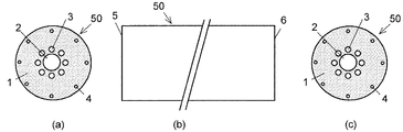
本発明を空孔アシストファイバ用の多孔質母材及び透明ガラス母材に適用した第1実施例について説明する。図1Aは本実施例に係る多孔質母材50の構成を、図1Bは透明ガラス母材60の構成を示す。透明ガラス母材60は、多孔質母材50を焼結して透明ガラス化して得られたものである。各図の(a)は左側面図、(b)は正面図、(c)は右側面図である。
多孔質母材50及び透明ガラス母材60は、いずれもSiO2で構成されたクラッド1、クラッド1内の中心に設けられたコアガラス挿入用の空孔2、クラッド1の等価屈折率を低下させるために該空孔2の周りに設けられた空孔3及び空孔4を有している。多孔質母材50及び透明ガラス母材60の両端面5及び6はいずれもフラットな面であり、一端面から他端面までの断面形状が同一の構造を有している。
A first embodiment in which the present invention is applied to a porous preform and a transparent glass preform for hole assist fibers will be described. FIG. 1A shows the configuration of the
The
図2に示すように、多孔質母材50は、長尺な金属容器及び長尺な金属ロッドを用いた型抜きにより製造される。金属容器11は、内径D0が152mm、長さL0が60cmのステンレス製の円筒状容器であり、上面及び下面にはそれぞれ取り外し可能な上蓋及び下蓋(いずれも図示せず)が装着されている。金属容器11は、中から多孔質母材50を取り出せるように半割構造になっている。金属容器11の内面、上蓋の下面及び下蓋の上面は、いずれも表面粗さが0.01μm〜0.03μm程度となるように鏡面研磨されている。また、金属容器11の内径公差は+0.08/−0.010mmである。
As shown in FIG. 2, the
金属ロッドは、空孔2を形成するための1本の金属ロッド12、空孔3を形成するための8本の金属ロッド13、空孔4を形成するための8本の金属ロッド14から成る。いずれも長さが約1000mmであり、それぞれ空孔の内径寸法に対応する外径寸法を有している。金属ロッド12〜14は、その表面粗さが0.01μmから0.03μm程度となるように外周表面が鏡面研磨されている。また、金属ロッド12〜14は、真直度が0.06/1000mm、外径公差が+0/−0.00mm、真円度が5μm/2000mmであり、外径の寸法精度、表面粗さ、真直度、真円度の優れた金属ロッドから成る。なお、多孔質母材50の空孔2〜4が断面円形状であるため、断面円形状の金属ロッドを用いたが、空孔2〜4の断面形状は多角形(正方形、六角形等)でも良く、この場合は、金属ロッドの断面形状も多角形(正方形、六角形等)にする。
The metal rod is composed of one
多孔質母材50は以下の方法により製造する。
まず、金属容器11の内部に上記金属ロッド12、13、14をそれぞれ所定の位置に配置する。金属ロッド12〜14は、金属容器11の両端で引っ張り真っ直ぐした状態で配置する。これにより金属ロッド12〜14の真直度が一層良くなる。
The
First, the
続いて、金属容器11内に硬化性樹脂を含んだ石英ガラス溶液と硬化剤の混合液16を注入する。
本実施例では、石英ガラス溶液として、粒径が2μm以下(好ましくは1μm以下)のシリカ粉末を分散剤(テトラメチルアンモニウムヒドロキシド溶液)と蒸留水の混合液に入れたものを用いた。硬化性樹脂には液体樹脂であるデナコールEX512(ナガセケムテックス株式会社)を用いた。硬化剤にはトリエチレンテトラミンを用いた。硬化性樹脂を含んだ石英ガラス溶液の配合比(重量%)は、シリカ粉末87%、蒸留水21.2%、分散剤2.7%、硬化性樹脂10.1%とした。シリカ粉末の配合量を多くすることにより、焼結時の割れやクラックを無くし、収縮率を小さくする(つまり、収縮量を小さく抑える)ことができる。なお、収縮量を小さく抑えるために、シリカ粉末の配合量を90%程度まで増やすことができる。
Subsequently, a
In this example, a silica glass solution in which silica powder having a particle size of 2 μm or less (preferably 1 μm or less) was added to a mixture of a dispersant (tetramethylammonium hydroxide solution) and distilled water was used. Denacol EX512 (Nagase ChemteX Corporation), which is a liquid resin, was used as the curable resin. Triethylenetetramine was used as the curing agent. The compounding ratio (wt%) of the quartz glass solution containing the curable resin was 87% silica powder, 21.2% distilled water, 2.7% dispersant, and 10.1% curable resin. By increasing the amount of silica powder, without cracking or crack during sintering, low shrinkage Kusuru (i.e., suppress the amount of shrinkage) can. In order to keep the shrinkage amount small, the blending amount of the silica powder can be increased to about 90%.
次に、石英ガラス溶液が自己硬化反応により固化した後、固化体から上記金属ロッド12〜14および金型容器11を脱離し、乾燥させる。これにより、空孔2〜4を有する多孔質母材50が得られる。このようにして得られた多孔質母材50は、その上面と下面がフラットな面で、且つ上面、下面並びに外周面の表面粗さが小さい平滑な母材となる。また、空孔2〜4の内面の表面粗さも小さく、且つ真直度および真円度の優れた母材となる。
Next, after the quartz glass solution is solidified by a self-curing reaction, the
上記方法により得られた多孔質母材50は、次の方法により焼結して透明カラス化される。
まず、図3(a)に示すように、多孔質母材50の上端に石英ガラス管21の下端を融着接続する。石英ガラス管21の内径は多孔質母材50の外径とほぼ同じであり、その内部には細径の石英ガラス管23が取り付けられている。石英ガラス管23は、石英ガラス管21の上端に固定されており、石英ガラス管23の下端は石英ガラス管21の下端よりもやや上に位置している。従って、石英ガラス管21を多孔質母材50に融着接続したとき、石英ガラス管23の下端部は多孔質母材50の上端部から離間するようになっている。
The
First, as shown in FIG. 3A, the lower end of the
続いて、図4に示すように、保護管25(グラッシーカーボン管、あるいはアルミナ炉心管、石英ガラス管)を高温電気炉26で温度1600℃〜1750℃に加熱し、その保護管25内に、石英ガラス管21及び23と共に多孔質母材50を、上から下に向かって所定の速度(50mm/h〜120mm/hの範囲から選択した値に設定する。)で挿入し、焼結を行う。石英ガラス管21は多孔質母材50の挿入のガイド管として利用することができる。
多孔質母材50を挿入する際、細径の石英ガラス管23内にHeガスと塩素ガスの混合ガス(塩素ガス分圧は0.03mmHg〜60mmHgの範囲から選択した値に設定)を流す。この結果、混合ガスは、多孔質母材50の空孔2〜4内を通って保護管25内に入り、保護管25の出口27から排出される。また、保護管25内には、入口28から不活性ガス(好ましくはHeガス、総流量5L/min〜8L/min)を導入する。保護管25内に導入された不活性ガスは、多孔質母材50の周りを通り、保護管25の出口27から矢印F5で示すように排出される。図4において、混合ガスの流れを矢印F1〜F3で示し、不活性ガスの流れを矢印F4〜F5で示す。
Subsequently, as shown in FIG. 4, the protective tube 25 (glassy carbon tube, alumina furnace core tube, quartz glass tube) is heated to a temperature of 1600 ° C. to 1750 ° C. in the high temperature
When the
これにより、多孔質母材50の内部には混合ガスが流通し、外周は不活性ガス(Heガス)で覆われた状態で焼結が行われる。そのため、多孔質母材50内のOH基、不純物の拡散速度が上がり、これらOH基及び不純物が混合ガスと共に多孔質母材50の内部から外周に向かって移動し、不活性ガス中に排出される。この結果、多孔質母材50が焼結され、透明ガラス化されることにより得られた透明ガラス母材60からはOH基や不純物が除去される。
As a result, the mixed gas flows inside the
本実施例では、外径が25mm、長さが540mmの多孔質母材50を、挿入速度を90mm/h、高温電気炉26の温度を1650℃、高温電気炉26内に入れる総Heガス流量を5L/min、多孔質母材50内に入れるHeガスと塩素ガスの混合ガスの塩素分圧を40mm/Hgとして焼結を行ったところ、多孔質母材50の約82%に収縮した透明ガラス母材60が得られた。また、透明ガラス母材60の空孔2〜4の真直度は0.1/500mm未満、真円度は1.6μm/500mm未満であった。
In this embodiment, a
一方、高温電気炉26の温度を1600℃とした場合、焼結した母材の一部分に透明ガラス化が不十分のところが生じた。また塩素ガス分圧が0.2mmHg以下の場合、得られた母材のOH基による吸収損失が増大した。また、入口28から矢印F3で示す方向に流したHeガスの流量が2L/min以下では、母材の中心付近に不透明な部分が生じた。このような現象は、母材の外周の温度が高くなり、中心付近よりも先に焼結が進んだためと考えられる。
On the other hand, when the temperature of the high-temperature
このように、本実施例では、空孔2〜4の真直度、真円度の優れた透明ガラス母材60を得ることができる。また、CH基やOH基等、不純物の少ない透明ガラス母材60を得ることができる。
Thus, in this embodiment, it is possible to obtain the transparent
なお、本実施例では、保護管25内に挿入した多孔質母材50を上から下に向かって移動させながら焼結したが、多孔質母材50を保護管25内の最下部まで引き下げておき、下から上に向かって移動させながら焼結を行なっても良い。このように焼結を行なうと、石英ガラス管21と多孔質母材50の融着部付近から熱効率良く焼結が進行して透明ガラス化を容易に行なうことができる。また、多孔質母材50中に含有している不純物や水分が多孔質母材50の外部に拡散放出された後、再び母材内に入り込みにくいという点でも好ましい。
In this embodiment, the
図5は本発明の第2実施例に係る空孔アシストファイバ用の透明ガラス化母材を示す。この透明ガラス化母材61は、図1Aに示す多孔質母材50の空孔2内にコアガラスロッド7を挿入した状態で焼結して透明ガラス化して得られたものである。コアガラスロッド7は、SiO2にGeO2を約20モル%添加したガラスから成る。
FIG. 5 shows a transparent vitrification base material for hole assist fiber according to a second embodiment of the present invention. This transparent
第1実施例に示したように、焼結により多孔質母材50は約82%に収縮して透明ガラス母材60となる。そこで、コアガラスロッド7は、約82%に収縮した後の空孔2の内径にほぼ近い外径のものを挿入しておく。従って、空孔2内にコアガラスロッド7がわずかに隙間を持って挿入されるが、多孔質母材50に石英ガラス管21を融着する際に、その部分において多孔質母材50を収縮させ、上記母材の融着部にコアガラスロッドを密着固定することができる。これにより、保護管25内に多孔質母材50を挿入する際に空孔2からコアガラスロッド7が抜け落ちることがない。
As shown in the first embodiment, the
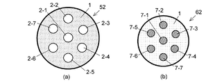
図6の(a)及び(b)に本発明の第3実施例に係るマルチコアファイバ用の多孔質母材及び透明ガラス母材の左側面図を示す。この多孔質母材52は、SiO2で構成されたクラッド2内にコアガラス層入用の7個の空孔2−1〜2−7を有している。この多孔質母材52も、空孔アシストファイバ用の多孔質母材50と同様、金属容器及び金属ロッドを用いた型抜きにより形成されている。
FIGS. 6A and 6B are left side views of a porous preform and a transparent glass preform for a multi-core fiber according to a third embodiment of the present invention. The
透明ガラス母材62は、上記多孔質母材52の7個の空孔2−1〜2−7それぞれに、コアガラスロッド7−1〜7−7を挿入した状態で焼結して透明ガラス化することにより得られたものである。コアガラスロッドは、SiO2にGeO2を約20モル%添加したガラスから成る。本実施例においても、空孔の内径の約82%に相当する外径のコアガラスロッドを用いている。
The transparent
図7の(a)及び(b)に本発明の第4実施例に係るマルチコアファイバ用の多孔質母材53及び透明ガラス母材63を示す。この多孔質母材53は、SiO2クラッド1の中にコア挿入用の空孔2−1〜2−7と、それら空孔2−1〜2−7の周りに設けられた複数の細孔8を有している。この多孔質母材53も、空孔アシストファイバ用の多孔質母材50と同様、金属容器及び金属ロッドを用いた型抜きにより形成されている。
7A and 7B show a
透明ガラス母材63は、上記多孔質母材53の7個の空孔2−1〜2−7それぞれに、コアガラスロッド7−1〜7−7を挿入した状態で焼結して透明ガラス化することにより得られたものである。本実施例においても、コアガラスロッドは、SiO2にGeO2を約20モル%添加したガラスから成り、空孔の内径の約82%に相当する外径を有するものが用いられている。
The transparent
細孔8は、クラッド1の等価屈折率を下げるために設けられており、空孔2−1〜2−7と接しない範囲で該空孔の近傍に設けることによって、コア内に光信号をより強く閉じ込めて伝送させることができる。このように本実施例においても、多孔質母材53を製造する段階で複数の空孔及び細孔を容易に設けることができる。
The
図8の(a)及び(b)に本発明の第5実施例に係る高NA化を図ったパンダファイバ用の多孔質母材54及び透明ガラス母材64を示す。多孔質母材54は、SiO2クラッド1の中心に設けられたコアガラスロッド挿入用の空孔2と、その両側に設けられた空孔2−1及び空孔2−2と、周縁部に設けられた複数の細孔8を有している。細孔8は、クラッド1の等価屈折率を下げるために設けられている。これにより、はじめて高NAパンダファイバを実現することができ、小さな曲げ半径で曲げても損失増加の低いファイバを得ることができる。
FIGS. 8A and 8B show a panda fiber
透明ガラス母材64は、上記多孔質母材54の空孔2にコアガラスロッド7を、空孔2−1及び空孔2−2にガラスロッド7−1及び7−2を挿入した状態で焼結して透明ガラス化することにより得られたものである。コアガラスロッド7は、SiO2にGeO2を約20モル%添加したガラスから成り、空孔2の内径の約82%に相当する外径を有するものが用いられている。また、ガラスロッド7−1及び7−2は、B(ホウ素)を添加したSiO2ガラスから成り、空孔2−1及び空孔2−2の内径の約82%に相当する外径を有するものが用いられている。
In the transparent
図9に本発明の第6実施例に係る超高NA化を目指した空孔アシストファイバ用透明ガラス母材65を示す。実施例1と同様、この透明ガラス母材65は多孔質ガラス母材(図示せず)を焼結により透明ガラス化したもので、外形が円形状のSiO2クラッド1と、その中心に設けられた断面矩形状の貫通孔31と、該貫通孔31に配置された断面円形状のコア32と、該コア31の外周を覆うFを添加したSiO2層33とから構成されている。Fを添加したSiO2層33は、その外周が上記貫通孔31の内周面と4箇所で接するように配置されており、この結果、Fを添加したSiO2層33とSiO2クラッド1の間に空隙が存在する。また、貫通孔31の周囲のクラッド1内には、クラッド2の等価屈折率を下げるための複数の空孔3が設けられており、これにより超高NA空孔アシストファイバを低コストで、かつ空孔3の形成に伴う不要な損失増加を伴わないで実現することができる。なお、従来方法では空孔3を形成した空孔アシストファイバを得るには、透明ガラス母材を得た後にドリルなどで機械的に空孔を形成するので、どうしても不要な損失増加を大きく伴う。このため、空孔をたくさん設けることはファイバの散乱損失等の損失を大きくするので、実現することは難しかった。
FIG. 9 shows a
本実施例の透明ガラス母材65から形成された光ファイバでは、コア32の外周がFを添加したSiO2層10で覆われているため、光信号をコア32に閉じこめ、さらにFを添加したSiO2層10の外周とSiO2クラッド1の間を空隙が存在することによって光信号をコア7内により一層強く閉じ込めることができる。また、クラッド2内には、空孔3を設けてクラッド1の等価屈折率を下げてあるため、光ファイバのコア7内への光信号を強く閉じ込めることができる。さらに、SiO2クラッド1内に空孔や空隙が存在するため、ファイバを小さな曲げ半径で曲げても損失の増加を抑えることができ、曲げにきわめて強いファイバを実現することができる。
In the optical fiber formed from the
図10に本発明の第7実施例に係る超高NA化を目指した別の空孔アシストファイバ用透明ガラス母材66を示す。第6実施例と同様、この透明ガラス母材66の多孔質ガラス母材を焼結により透明ガラス化したもので、外形が円形状のSiO2クラッド1と、その中心に設けられた断面形状が円形の貫通孔31と、該貫通孔31に配置された高屈折率の矩形状のコア32と、該コア32の外周を覆うFを添加したSiO2層33とから構成されている。Fを添加したSiO2層33は、その外周が上記貫通孔31の内周面と4箇所で接するように配置されており、この結果、Fを添加したSiO2層33とSiO2クラッド1の間に空隙が存在する。また、貫通孔31の周囲のクラッド1内には、クラッド2の等価屈折率を下げるための複数の空孔3が設けられている。
FIG. 10 shows another
本実施例の透明ガラス母材66から形成された光ファイバでは、コア32の外周がFを添加したSiO2層10で覆われているため、光信号をコア32に閉じこめ、さらにFを添加したSiO2層10の外周とSiO2クラッド1の間を空隙が存在することによって光信号をコア7内により一層強く閉じ込めることができる。また、クラッド1内には、空孔3を設けてクラッド1の等価屈折率を下げてあるため、光ファイバのコア7内への光信号を強く閉じ込めることができる。さらに、SiO2クラッド1内に空孔や空隙が存在するため、ファイバを小さな曲げ半径で曲げても損失の増加を抑えることができ、曲げにきわめて強いファイバを実現することができる。
In the optical fiber formed from the
図11に本発明の第8実施例に係る高NA化(NA>0.5)を目指したマルチコアファイバ用の透明ガラス母材67を示す。この透明ガラス母材67は、図9に示した透明ガラス母材65のコア周辺の構造をSiO2クラッド1に7個設けることによりマルチコアファイバ構造を実現したものである。従って、この透明ガラス母材67から形成されるマルチコアファイバにおいても、各コア7内に光信号を強く閉じ込めて伝送させることができ、且つ各コア間の干渉を極めて小さく抑えたファイバを実現することができる。したがって、一つのファイバで超大容量、超高速の情報を伝送させることが出来る。またマルチコアファイバの両端に接続するファイバと低接続損失で接続することができる。なお、クラッド1に設けるコア32の数は7個に限らず、例えば13個程度設けても良い。また、図9に示した透明ガラス母材65のように、貫通孔の周囲に、クラッド1の等価屈折率を下げるための複数の空孔を設けても良い。
FIG. 11 shows a transparent glass preform 67 for multi-core fiber aiming at high NA (NA> 0.5) according to the eighth embodiment of the present invention. The transparent glass preform 67 is obtained by realizing the multi-core fiber structures by providing seven structure around the core of the
図12に本発明の第9実施例に係る超高NA化(NA:>0.6)を目指した空孔アシストファイバ用の透明ガラス母材68を示す。これは図9に示した空孔アシストファイバ用の透明ガラス母材65の外形を円形から八角形にしたもので、その他の構成は同じである。外形を八角形にすることによってファイバ同士の接続を容易にし、また、ファイバの敷設の際にファイバを安定して固定することができる。なお、外形を八角形にした場合、透明ガラス母材68を線引きしてファイバにする際に角(かど)が丸くなりやすいが、ファイバの角が丸くなっていても良い。
FIG. 12 shows a
本発明は上記した実施例以外の光ファイバ用の多孔質母材及び透明ガラス母材にも適用でき、その例を図13に示す。同図(a)は曲げ損失を小さくした空孔アシストファイバ用多孔質母材69、同図(b)はコア内への光の閉じ込めを強くしたマルチコアファイバ用多孔質母材70、同図(c)はコア内への光の閉じ込めを強くし、且つ曲げ損失を小さくしたパンダファイバ用多孔質母材71、同図(d)はフォトニック結晶型ファイバ用多孔質母材72、同図(e)は敷設及びフイバ同士の接続を容易にしたマルチコアファイバ用多孔質母材73、同図(f)は敷設及びファイバ同士の接続を容易にした空孔アシストファイバ用多孔質母材74である。これらの多孔質母材は、いずれも貫通孔を有しているため、焼結時に該貫通孔にヘリウムガス及び塩素ガスの混合ガスを流すことができるため、OH基及びCH基、不純物等を効率よく排出することができる。
The present invention can be applied to a porous preform and a transparent glass preform for optical fibers other than the above-described embodiments, and an example is shown in FIG. The figure (a) is the porous preform |
図14は、焼結時に多孔質母材に取り付ける石英ガラス管の別の実施例を示す。図14に示すように、多孔質母材50には、上端部及び下端部にそれぞれ石英ガラス管21、石英ガラス管211が取り付けられている。
石英ガラス管211は、石英ガラス管21から送られる混合ガスが、多孔質母材50の空孔2〜4を通って保護管25の出口27(図4参照)に向かわせるのに有効であり、これにより、空孔2〜4が変形することを抑えることができる。また、透明ガラス母材を高温電気炉内に挿入しながら延伸して線引きする際に石英ガラス管211を利用することができる。
FIG. 14 shows another embodiment of a quartz glass tube attached to a porous base material during sintering. As shown in FIG. 14, a
The
図15は、焼結時に多孔質母材に取り付ける石英ガラス管の他の実施例を示す。この石英ガラス管212は第1実施例に示した石英ガラス管21と異なり、二重管構造になっていない。このような石英ガラス管212を用いた場合でも、焼結時に混合ガスを多孔質母材50内に流すことができる。
FIG. 15 shows another embodiment of a quartz glass tube attached to a porous base material during sintering. Unlike the
図16に多孔質母材50の両端に石英ガラス管を融着接続する装置を示す。これはガラス旋盤800に石英ガラス管21及び211をチャックし、上記石英ガラス管21及び212に多孔質母材50の両端を挿入保持する。そして、一方の石英ガラス管21側からロータリージョイント81、配管82を介して矢印83で示すように不活性ガスを流し、反対側の石英ガラス管211側に上記不活性ガスを排出させながら石英ガラス管211と多孔質母材50を酸水素バーナー84に酸素85と水素86を流して火炎87を発生させて融着する。なお両石英ガラス管は旋盤で矢印方向に回転させておく。
FIG. 16 shows an apparatus for fusion-bonding quartz glass tubes to both ends of a
図17に多孔質母材を透明ガラス化する方法を示す。この実施例では、保護管25に代えて保護管29が用いられる。この保護管29は、不活性ガスを導入するための入口28が上下2段に設けられている点が、第1実施例に示した保護管25と異なる。このように入口28を増やすことにより、保護管29内をできる限り不活性ガス雰囲気に保つことができる。これにより、多孔質母材50の外周の温度を下げることができ、該多孔質母材50の中心部から焼結を行わせることができる。
FIG. 17 shows a method for forming a porous base material into transparent glass. In this embodiment, a
図18は多孔質母材を透明ガラス化する別の方法を示したものである。この実施例では、多孔質母材50の外周を石英ガラス管213で覆った状態で保護管25内に挿入するようにした点が第1実施例と異なる。高温電気炉26で加熱、焼結すると、通常は母材外周からの焼結が進行しやすく、母材の中心部まで十分に焼結されない場合が多い。これに対して、多孔質母材50の外周を石英ガラス管213で覆うことにより、輻射熱により多孔質母材50の中心部から焼結し易くなり、透明な光ファイバ母材を得ることができる。
FIG. 18 shows another method for forming a porous base material into transparent glass. This embodiment is different from the first embodiment in that the
図19は多孔質母材を透明ガラス化する、さらに別の他の方法を示したものである。この実施例では、多孔質母材50を保護管25の下方から上方に向けて所定速度で引き上げながら高温電気炉26で焼結して透明ガラス化した点が第1実施例と異なる。
保護管25内には下部の入口28から不活性ガス(好ましくはHeガス)を流し、上部の出口27から排気する。細径の石英ガラス管23内に送り込んだHeガスと塩素ガスの混合ガスは多孔質母材50内の空孔を通って保護管25の出口27から排出する。
FIG. 19 shows still another method for forming a porous base material into a transparent glass. This embodiment is different from the first embodiment in that the
An inert gas (preferably He gas) flows from the
図20は透明ガラス母材を線引きする方法を示す図である。この方法では、透明ガラス母材60を高温電気炉31内に所定速度で送り込みながら、上記母材60の下端側から延伸して線引きする。線引き後の光ファイバ33はドラム35に巻き取られる。線引きする際、細径の石英ガラス管23内には矢印F6のごとく不活性ガス(好ましくはHeガス、あるいはAr、N2ガスでも良い。)を送り込み、透明ガラス母材60内に流すことにより、透明ガラス母材60内が外部圧力と比較して常に所望の圧力になるようにする。これにより、透明ガラス母材60に一定圧力が加えられ、この結果、透明ガラス母材60の空孔2〜4の形状を制御することができる。一定の圧力を加えておくことは透明ガラスファイバ60内の空孔2〜4の形状を均一に保つ上で極めて重要である。
なお、上記透明ガラス母材60を線引きしている間は、該母材60の外周に矢印F7で示すように不活性ガスを流す。また高温電気炉31の下端側には矢印F8で示すように不活性ガスを流し、上記不活性ガスと共に矢印F9で示すように排出させる。
FIG. 20 is a diagram illustrating a method of drawing a transparent glass base material. In this method, the
In addition, while drawing the said transparent
本発明の方法により得られた透明ガラス母材を高温電気炉内に所定速度で送り込みながら線引きして外径が125μm、コア径が10μm、長さが約10kmの光ファイバとし、この光ファイバの散乱損失を測定した。なお、本発明では、透明ガラス母材を線引きすることにより最大約800kmの長さの光ファイバを得ることができるが、ここでは損失(散乱損失、吸収損失、OH基等の不純物による吸収損失)の測定を目的とするため、約10kmの長さとした。 The transparent glass preform obtained by the method of the present invention is drawn while being fed into a high-temperature electric furnace at a predetermined speed to obtain an optical fiber having an outer diameter of 125 μm, a core diameter of 10 μm, and a length of about 10 km. Scattering loss was measured. In the present invention, an optical fiber having a maximum length of about 800 km can be obtained by drawing a transparent glass preform. Here, loss (scattering loss, absorption loss, absorption loss due to impurities such as OH groups) is obtained. For the purpose of measurement, the length was about 10 km.
その結果、波長1.55μmにおいて、0.27dB/kmの損失であった。その損失の内訳を調べたところ、レーリー散乱損失が0.16dB/km、構造不整による散乱損失が0.03dB/km、赤外部、紫外部における固有吸収と不純物による吸収の損失が0.08dB/kmであった。そして、波長1.39μmにおける損失が、従来の方法で製造した母材を線引きして得たファイバの上記損失(約8dB/km)に比し大幅に低下し、2dB/kmにまで低下していることがわかった。このように構造不整による散乱損失が極めて低く、不純物による吸収損失が低いという結果は、空孔2内に挿入したガラスロッドとSiO2クラッド層との界面が均一であること、及び母材内の脱OH基が空孔内に流すHeガスと塩素ガスによって効率良く行われていることを裏付ける結果であった。従来のように透明ガラス化した母材にHeガスと塩素ガスを流した母材ではこのような低OH基は実現できなかった。なおCH基、Si−H基による損失は無いことが確認できた。
As a result, the loss was 0.27 dB / km at a wavelength of 1.55 μm. When the breakdown of the loss was examined, the Rayleigh scattering loss was 0.16 dB / km, the scattering loss due to structural irregularity was 0.03 dB / km, the intrinsic absorption in the infrared part and the ultraviolet part and the absorption loss due to impurities were 0.08 dB / km. km. The loss at the wavelength of 1.39 μm is significantly lower than the loss (about 8 dB / km) of the fiber obtained by drawing the base material manufactured by the conventional method, and is reduced to 2 dB / km. I found out. As described above, the scattering loss due to the structural irregularity is extremely low, and the absorption loss due to the impurities is low. The result is that the interface between the glass rod inserted into the
このように、本実施例では、従来の、母材の外周にのみ不活性ガスを流す透明ガラス化方法、ゾルゲル法では実現が困難な良好な結果を得ることができた。また、母材外形寸法を金属容器の寸法で容易に制御することができることが分かる。 Thus, in the present Example, the favorable result which was difficult to implement | achieve with the conventional transparent vitrification method and the sol gel method which flow an inert gas only to the outer periphery of a base material was able to be obtained. It can also be seen that the base metal outer dimensions can be easily controlled by the dimensions of the metal container.
なお、本発明は上記実施例に限定されない。
上記実施例では、多孔質母材(固化体)を乾燥させた後、この多孔質母材の空孔内にコア用ガラスロッドを挿入し、この状態で高温加熱して透明ガラス母材を得るようにしたが、孔質母材を透明ガラス化して透明ガラス母材を得た後、この透明ガラス母材の空孔内にコア用ガラスロッドを挿入し、透明ガラス母材を外周から高温に加熱して、コア用ガラスロッドを上記透明ガラス母材内に融着させるようにしても良い。
In addition, this invention is not limited to the said Example.
In the above embodiment, after the porous base material (solidified body) is dried, the core glass rod is inserted into the pores of the porous base material and heated in this state to obtain a transparent glass base material. However, after obtaining a transparent glass base material by converting the porous base material into a transparent glass, a core glass rod is inserted into the pores of the transparent glass base material, and the transparent glass base material is heated from the outer periphery to a high temperature. By heating, the core glass rod may be fused in the transparent glass base material.
ところで、光ファイバ母材の製造方法の一つに前述のゾルゲル法がある。ゾルゲル法では、液体状の原料物質(ゾル)を金型容器に注入し、ゲル状態を作った後に乾燥・焼結してガラス化することによって光ファイバ母材を製造する。液体状の原料物質を金型容器に注入する点で第1実施例等で説明した多孔質母材の製造方法と類似する。
しかし、ゾルゲル法では有機オキシシラン(例えば、テトラエトキシシラン)溶液と純水による加水分解反応により石英ガラスを生成しており、形状の制御が難しい。これに対して、本実施例では、上述したように、硬化性樹脂を含んだ石英ガラス溶液を用いているため、ゾルゲル法に比して極めて形状の制御が容易であり、割れやクラックの発生がほとんど無い。
By the way, the above-mentioned sol-gel method is one of the methods for producing an optical fiber preform. In the sol-gel method, an optical fiber preform is manufactured by pouring a liquid source material (sol) into a mold container, forming a gel state, drying, sintering, and vitrifying. It is similar to the method for manufacturing the porous base material described in the first embodiment and the like in that the liquid raw material is injected into the mold container.
However, in the sol-gel method, quartz glass is generated by a hydrolysis reaction with an organic oxysilane (for example, tetraethoxysilane) solution and pure water, and it is difficult to control the shape. In contrast, in this example, as described above, since a quartz glass solution containing a curable resin is used, the shape can be controlled extremely easily compared to the sol-gel method, and cracks and cracks are generated. There is almost no.
また、ゾルゲル法は加水分解反応で石英ガラスを生成しており、該石英ガラスの生成率が低い。さらに、ゾルゲル法では、焼結による光ファイバ母材の径方向及び軸方向の収縮率の差が30%〜60%と大きく異なるので、割れやクラックが発生しやすい。そのため、大型の光ファイバ母材の製造が難しい。さらに、ゾルゲル法では、1日以上の長時間をかけて加水分解反応を起こさせないと割れやクラックが起き易く、かつ乾燥及び高温加熱も10日以上の長時間をかけて行わないと割れやクラックが起きる。 The sol-gel method produces quartz glass by a hydrolysis reaction, and the production rate of the quartz glass is low. Furthermore, in the sol-gel method, the difference in shrinkage between the radial direction and the axial direction of the optical fiber preform due to sintering is greatly different from 30% to 60%, so that cracks and cracks are likely to occur. Therefore, it is difficult to manufacture a large optical fiber preform. Furthermore, in the sol-gel method, cracks and cracks are likely to occur unless a hydrolysis reaction is caused over a long period of one day or more, and cracks and cracks occur unless drying and high-temperature heating are performed over a long period of 10 days or longer. Happens.
それに対して本実施例ではシリカ粉末を分散剤と蒸留水の混合液に入れて固化させ、この固化体を乾燥、加熱しているので、乾燥・加熱時の径方向及び軸方向の収縮率の差が小さく、また、収縮率も約18%(=(100−82)%)と小さいため、割れやクラックの発生がほとんど無い。そのためにゾルゲル法の1/10以下の時間で固化させることができ、乾燥もゾルゲル法の1/2以下の時間で且つ50℃から120℃の低温でよい。なお、金属容器に上記溶液を真空脱法して入れることにより気泡の混入がほとんど無くなり、固化したガラス母材内に空隙がほとんど形成されない。 On the other hand, in this example, silica powder is put into a mixed liquid of a dispersant and distilled water to solidify, and the solidified body is dried and heated. Therefore, the shrinkage in the radial and axial directions during drying and heating is reduced. Since the difference is small and the shrinkage rate is as small as about 18% (= (100−82 ) % ) , there is almost no occurrence of cracks or cracks. Therefore, it can be solidified in a time of 1/10 or less of the sol-gel method, and drying can be performed in a time of 1/2 or less of the sol-gel method and at a low temperature of 50 ° C to 120 ° C. Note that, when the above solution is vacuum degassed into the metal container, bubbles are hardly mixed in, and voids are hardly formed in the solidified glass base material.
また、ゾルゲル法では通常、オルトケイ酸テトラメチル(TMOS)やオルトケイ酸テトラエチル(TEOS)を水と反応させてシリカゲルにするが、このシリカゲル中にヒドロキシ基(OH基)が含まれてしまう。この他、CH基、Si−H基もOH基と同様にシリカゲル中に含まれる。シリカゲルを乾燥・焼結してガラス化するまでの過程でOH基、CH基、Si−H基を取り除くことは難しいため、ゾルゲル法により得られた光ファイバ母材はOH基、CH基、Si−H基を含み、このような光ファイバ母材から作られる光ファイバは、光通信で使用する波長帯における損失が大きくなる。 In the sol-gel method, tetramethyl orthosilicate (TMOS) or tetraethyl orthosilicate (TEOS) is usually reacted with water to form silica gel. However, this silica gel contains a hydroxy group (OH group). In addition, CH groups and Si—H groups are also included in the silica gel as in the case of OH groups. Since it is difficult to remove OH groups, CH groups, and Si-H groups in the process from drying and sintering to vitrification of silica gel, optical fiber preforms obtained by the sol-gel method are OH groups, CH groups, Si An optical fiber including a —H group and made from such an optical fiber preform has a large loss in a wavelength band used for optical communication.
これに対して、本実施例では、多孔質母材の空孔内から外周に向けてHeガスと塩素ガスを流しながら焼結して透明ガラス化するので、透明ガラス母材の中から不要な物を蒸発、除去することが容易にできる。このため、透明ガラス母材中にCH基、Si−H基、OH基がほとんど含まれず、これらによる光損失を低く抑えた光ファイバを得ることができる。 On the other hand, in this example, sintering is performed while flowing He gas and chlorine gas from the pores of the porous base material toward the outer periphery, so that the glass is formed into transparent glass. Things can be easily evaporated and removed. For this reason, it is possible to obtain an optical fiber that hardly contains CH groups, Si—H groups, and OH groups in the transparent glass base material and suppresses optical loss due to these.
上述したように、固化体のガラス化による収縮率は約18%(=(100−82)%)であることから、得られる光ファイバ用ガラス母材の外径は125mm、長さは533mm、空孔の内径は10mmであった。また、この光ファイバ用ガラス母材の外形変動は0.5%以下で、かつその表面粗さは0.5μm以下であった。外形変動の低さ、言い換えると外形の均一性は、内面が鏡面研磨されて表面粗さが0.01μmから0.03μmのステンレス製の容器を用いて光ファイバ用ガラス母材を製造したことにより得られたものである。この光ファイバ用ガラス母材の外形の均一性は形状の均一な光ファイバを実現する上で極めて有効である。また表面粗さが小さいことは光ファイバの機械的強度を向上させる上で極めて有効である。さらに光ファイバの構造パラメータ(コア径、外径など)を精確に設定することができる。すなわち、本実施例の光ファイバ用ガラス成形体では、径方向および軸方向のいずれもほとんど一様にわずかに縮小するだけであるので、構造パラメータの設計が容易である。 As described above, since the shrinkage due to vitrification of the solidified body is about 18% (= (100-82 ) % ) , the outer diameter of the obtained glass preform for optical fiber is 125 mm, the length is 533 mm, The inner diameter of the holes was 10 mm. Further, the variation in the outer shape of the glass preform for optical fiber was 0.5% or less, and the surface roughness was 0.5 μm or less. Low profile change, the uniformity of the contour in other words, the inner surface was produced glass preform for an optical fiber using a stainless steel container of 0.03μm from 0.01μm mirror polished with surface roughness It was obtained by this. The uniformity of the outer shape of the optical fiber glass preform is extremely effective in realizing an optical fiber having a uniform shape. Also, the small surface roughness is extremely effective in improving the mechanical strength of the optical fiber. Furthermore, the structural parameters (core diameter, outer diameter, etc.) of the optical fiber can be set accurately. That is, in the optical fiber glass molded body of the present example, both the radial direction and the axial direction are slightly reduced almost uniformly, so that the structural parameters can be easily designed.
コア用ガラスロッドの中心部に高屈折率の添加物と希土類元素を共添加したものを用いてもよい。上記希土類元素として、Er、Nd、Pr、Ce、Ybなどを用いることができる。また、上記コア用ガラスロッドの中心部内には希土類元素以外の共添加材料として、Al2O3、GeO2、P2O5、TiO2、などのSiO2の屈折率を高める添加物を添加しても良い。このように希土類元素やAl2O3、GeO2、P2O5を添加することにより光増幅器やレーザーを実現可能な光ファイバ母材を得ることができる。 You may use what added the high refractive index additive and rare earth elements to the center part of the glass rod for cores. As the rare earth element, Er, Nd, Pr, Ce, Yb, or the like can be used. Also, an additive for increasing the refractive index of SiO 2 such as Al 2 O 3 , GeO 2 , P 2 O 5 , TiO 2 is added as a co-additive material other than rare earth elements in the central portion of the core glass rod. You may do it. Thus, by adding rare earth elements, Al 2 O 3 , GeO 2 , and P 2 O 5 , an optical fiber preform capable of realizing an optical amplifier or a laser can be obtained.
金属容器、金属ロッド、金属管の材質はステンレス以外に、Au、Ni、Cuなどの材質でもよい。
硬化性樹脂を含んだSiO2のガラス原料溶液の配合比は上記した実施例(シリカ粉末87%、蒸留水21.2%、分散剤2.7%、硬化性樹脂10.1%)に限定されるものではない。本発明はシリカ粉末の調合量を圧倒的に多くしたことを特徴とするもので、この調合量は80%以上であれば良く、92%程度にまで多くすることができる。
The material of the metal container, the metal rod, and the metal tube may be a material such as Au, Ni, or Cu other than stainless steel.
The blending ratio of the glass raw material solution of SiO 2 containing the curable resin is limited to the above-described examples (
金属容器7の内径Do、長さLoは上記値に限定されず、内径Doは30mm〜300mm程度の大きさにすることができ、長さLoは20mm〜1000mm程度にすることができる。これらの内径Do、長さLoが大きいほど長尺の光ファイバを実現することができる。
The inner diameter Do and the length Lo of the
コア用空孔およびコア用ガラスロッドの直径Dcは10mm程度から100mm程度にすることができる。また、空孔アシストファイバ用、フォトニック結晶型ファイバ用、マルチコアファイバ用、パンダファイバ用のいずれのガラス母材の中心部周辺に設ける空孔の数量は限定されず、4個から30個の範囲から選ぶことができる。また、空孔の内径は0.5μmから5μmの範囲が好ましい。空孔の間隔も1μmから6μmの範囲から選ぶことができる。
本発明の光ファイバ用ガラス成形体の外径寸法は特に限定されるものではない。
The diameter Dc of the core hole and the core glass rod can be about 10 mm to about 100 mm. Further, the number of holes provided around the central portion of any glass base material for hole assist fiber, photonic crystal fiber, multi-core fiber, and panda fiber is not limited, and ranges from 4 to 30 You can choose from. The inner diameter of the holes is preferably in the range of 0.5 μm to 5 μm. The interval between the holes can be selected from a range of 1 μm to 6 μm.
The outer diameter dimension of the glass molded body for optical fibers of the present invention is not particularly limited.
1…コア用空孔
2…空孔内面
3…SiO2クラッド層
4…SiO2クラッド層の外周部
5…金属ロッド
6…硬化性樹脂を含んだ石英ガラス溶液と硬化剤の混合液
7…金属容器
8…金属容器の内面
9…細径空孔
10…細径金属ロッド
11…コア用ガラスロッド
12…SiO2ガラス薄層
1 ...
Claims (9)
硬化性樹脂とSiO2粒子を含むクラッド層用混合液と、該混合液を自己硬化反応により固化させるための硬化剤とを前記容器内に注入し、
前記クラッド層用混合液が固化した後、その固化体から前記容器及び前記金属ロッドを脱離して貫通孔を有する多孔質ガラス母材を形成し、
ヘリウムガスと塩素ガスの混合ガスを前記貫通孔に流しながら高温加熱することにより前記多孔質ガラス母材を透明ガラス化して光ファイバ用透明ガラス母材を製造する方法。 Place the metal rod in the container,
Clad layer mixed liquid containing curable resin and SiO 2 particles, and a curing agent for solidifying the mixed liquid by self-curing reaction is injected into the container,
After the mixed liquid for the cladding layer is solidified, the container and the metal rod are detached from the solidified body to form a porous glass base material having a through hole,
A method for producing a transparent glass preform for an optical fiber by converting the porous glass preform into a transparent glass by heating at a high temperature while flowing a mixed gas of helium gas and chlorine gas through the through hole.
前記高温加熱の際に、前記複数の貫通孔の一部に前記多孔質ガラス母材の屈折率よりも高い屈折率を有するガラスロッドを挿入し、残りの貫通孔にヘリウムガスと塩素ガスの混合ガスを一定流量で流したことを特徴とする請求項1〜7のいずれかに記載の光ファイバ用透明ガラス母材の製造方法。 The porous glass base material has a plurality of through-holes;
During the high temperature heating, a glass rod having a refractive index higher than the refractive index of the porous glass base material is inserted into a part of the plurality of through holes, and helium gas and chlorine gas are mixed into the remaining through holes. The method for producing a transparent glass preform for optical fiber according to any one of claims 1 to 7 , wherein gas is flowed at a constant flow rate.
前記高温加熱の際に、前記中心の貫通孔に前記多孔質ガラス母材の屈折率よりも高い屈折率を有するガラスロッドを挿入すると共に該ガラスロッドの両側の貫通孔に前記多孔質ガラス母材の屈折率よりも低い屈折率を有する、Bを添加したSiO2ガラスロッドを挿入し、その他の貫通孔の一方から他方に向けてヘリウムガスと塩素ガスの混合ガスを流すことを特徴とする請求項1〜7のいずれかに記載の光ファイバ用透明ガラス母材の製造方法。 The porous glass base material has a through hole located in the center of the porous glass base material, two through holes located on both sides thereof, and a through hole located in another porous glass base material. And
During the high temperature heating, a glass rod having a refractive index higher than the refractive index of the porous glass base material is inserted into the central through hole, and the porous glass base material is inserted into the through holes on both sides of the glass rod. A SiO 2 glass rod added with B having a refractive index lower than the refractive index is inserted, and a mixed gas of helium gas and chlorine gas is allowed to flow from one of the other through holes toward the other. Item 8. A method for producing a transparent glass preform for optical fiber according to any one of Items 1 to 7 .
Priority Applications (1)
| Application Number | Priority Date | Filing Date | Title |
|---|---|---|---|
| JP2013081158A JP5941430B2 (en) | 2013-04-09 | 2013-04-09 | Method for producing porous glass preform for optical fiber |
Applications Claiming Priority (1)
| Application Number | Priority Date | Filing Date | Title |
|---|---|---|---|
| JP2013081158A JP5941430B2 (en) | 2013-04-09 | 2013-04-09 | Method for producing porous glass preform for optical fiber |
Publications (3)
| Publication Number | Publication Date |
|---|---|
| JP2014201504A JP2014201504A (en) | 2014-10-27 |
| JP2014201504A5 JP2014201504A5 (en) | 2015-06-11 |
| JP5941430B2 true JP5941430B2 (en) | 2016-06-29 |
Family
ID=52352274
Family Applications (1)
| Application Number | Title | Priority Date | Filing Date |
|---|---|---|---|
| JP2013081158A Active JP5941430B2 (en) | 2013-04-09 | 2013-04-09 | Method for producing porous glass preform for optical fiber |
Country Status (1)
| Country | Link |
|---|---|
| JP (1) | JP5941430B2 (en) |
Cited By (1)
| Publication number | Priority date | Publication date | Assignee | Title |
|---|---|---|---|---|
| EP4129939A1 (en) * | 2021-08-03 | 2023-02-08 | Heraeus Quarzglas GmbH & Co. KG | Method and semi-finished product for manufacturing multi-core fibres |
Families Citing this family (2)
| Publication number | Priority date | Publication date | Assignee | Title |
|---|---|---|---|---|
| CN106876850A (en) * | 2015-12-14 | 2017-06-20 | 泰科电子(上海)有限公司 | Dielectric waveguide |
| KR102388688B1 (en) * | 2020-10-23 | 2022-04-20 | 비씨엔씨 주식회사 | Synthetic quartz manufacturing method |
Family Cites Families (4)
| Publication number | Priority date | Publication date | Assignee | Title |
|---|---|---|---|---|
| KR100334763B1 (en) * | 2000-04-18 | 2002-05-03 | 윤종용 | Fabrication method and device of holey optical fiber |
| JP2003329869A (en) * | 2002-05-17 | 2003-11-19 | Mitsubishi Cable Ind Ltd | Double-clad fiber and method for manufacturing the same |
| JP2009227548A (en) * | 2008-03-25 | 2009-10-08 | Photonic Science Technology Inc | Method for producing preform for photonic crystal fiber, and method for producing photonic crystal fiber |
| JP5520789B2 (en) * | 2010-11-12 | 2014-06-11 | 古河電気工業株式会社 | Optical fiber preform and optical fiber manufacturing method |
-
2013
- 2013-04-09 JP JP2013081158A patent/JP5941430B2/en active Active
Cited By (2)
| Publication number | Priority date | Publication date | Assignee | Title |
|---|---|---|---|---|
| EP4129939A1 (en) * | 2021-08-03 | 2023-02-08 | Heraeus Quarzglas GmbH & Co. KG | Method and semi-finished product for manufacturing multi-core fibres |
| WO2023011840A1 (en) * | 2021-08-03 | 2023-02-09 | Heraeus Quarzglas Gmbh & Co. Kg | Method and semi-finished product for fabricating multicore fibers |
Also Published As
| Publication number | Publication date |
|---|---|
| JP2014201504A (en) | 2014-10-27 |
Similar Documents
| Publication | Publication Date | Title |
|---|---|---|
| JP5572748B1 (en) | OPTICAL CONNECTION COMPONENT, ITS MANUFACTURING METHOD, AND OPTICAL CONNECTION COMPONENT MANUFACTURING MOLD CONTAINER | |
| US20200199008A1 (en) | Method for Manufacturing Optical Fiber Base Material and Optical Fiber Base Material | |
| FI77217C (en) | Process for producing a polarization preserving optical fiber | |
| US20040050110A1 (en) | Methods for fabricating optical fibers and optical fiber preforms | |
| JP5941430B2 (en) | Method for producing porous glass preform for optical fiber | |
| JP6396821B2 (en) | Method for manufacturing base material for multi-core fiber, and method for manufacturing multi-core fiber using the same | |
| JP5587959B2 (en) | Optical fiber preform manufacturing method | |
| JP5539594B2 (en) | Fiber and fiber manufacturing method | |
| JP5492325B2 (en) | Method for manufacturing optical fiber preform and optical fiber preform | |
| CN104536087A (en) | Multiple-material mixing microstructure fiber and preparation method thereof | |
| JP5603519B1 (en) | Optical fiber preform | |
| JP6010587B2 (en) | Method for manufacturing base material for multi-core fiber, and method for manufacturing multi-core fiber using the same | |
| JPS5992940A (en) | Production of optical fiber having pore | |
| JP5702850B2 (en) | Optical fiber preform | |
| JP6198225B2 (en) | Photonic crystal optical fiber preform manufacturing method | |
| WO2006025144A1 (en) | Bundle fiber | |
| JP2011020861A (en) | Method for producing optical fiber preform | |
| Yajima et al. | OH-free low loss single-mode fibre fabricated by slurry casting/rod-in-tube method | |
| KR100782475B1 (en) | The Method of Optical Fiber and Optical Fiber thereof | |
| JP5835823B1 (en) | Multi-core optical fiber preform manufacturing method | |
| KR100660148B1 (en) | Manufacturing Method for Optical Fiber Having Air-Holes | |
| JPS62167235A (en) | Production of base material for optical fiber | |
| JPS5918125A (en) | Manufacture of single-polarization single-mode optical fiber | |
| JP2015160784A (en) | Base material for multicore fiber and multicore fiber using the same, and method of manufacturing base material for multicore fiber and method of manufacturing multicore fiber using the same | |
| JP6081534B2 (en) | Optical fiber manufacturing method and optical fiber manufacturing apparatus |
Legal Events
| Date | Code | Title | Description |
|---|---|---|---|
| A521 | Request for written amendment filed |
Free format text: JAPANESE INTERMEDIATE CODE: A523 Effective date: 20150420 |
|
| A621 | Written request for application examination |
Free format text: JAPANESE INTERMEDIATE CODE: A621 Effective date: 20150420 |
|
| A977 | Report on retrieval |
Free format text: JAPANESE INTERMEDIATE CODE: A971007 Effective date: 20160121 |
|
| A131 | Notification of reasons for refusal |
Free format text: JAPANESE INTERMEDIATE CODE: A131 Effective date: 20160223 |
|
| A521 | Request for written amendment filed |
Free format text: JAPANESE INTERMEDIATE CODE: A523 Effective date: 20160421 |
|
| TRDD | Decision of grant or rejection written | ||
| A01 | Written decision to grant a patent or to grant a registration (utility model) |
Free format text: JAPANESE INTERMEDIATE CODE: A01 Effective date: 20160517 |
|
| A61 | First payment of annual fees (during grant procedure) |
Free format text: JAPANESE INTERMEDIATE CODE: A61 Effective date: 20160520 |
|
| R150 | Certificate of patent or registration of utility model |
Ref document number: 5941430 Country of ref document: JP Free format text: JAPANESE INTERMEDIATE CODE: R150 |
|
| R250 | Receipt of annual fees |
Free format text: JAPANESE INTERMEDIATE CODE: R250 |
|
| R250 | Receipt of annual fees |
Free format text: JAPANESE INTERMEDIATE CODE: R250 |
|
| R250 | Receipt of annual fees |
Free format text: JAPANESE INTERMEDIATE CODE: R250 |
|
| R250 | Receipt of annual fees |
Free format text: JAPANESE INTERMEDIATE CODE: R250 |
|
| R250 | Receipt of annual fees |
Free format text: JAPANESE INTERMEDIATE CODE: R250 |