JP5940407B2 - Transport device - Google Patents

Transport device Download PDF

Info

Publication number
JP5940407B2
JP5940407B2 JP2012169793A JP2012169793A JP5940407B2 JP 5940407 B2 JP5940407 B2 JP 5940407B2 JP 2012169793 A JP2012169793 A JP 2012169793A JP 2012169793 A JP2012169793 A JP 2012169793A JP 5940407 B2 JP5940407 B2 JP 5940407B2
Authority
JP
Japan
Prior art keywords
motor
roller
article
transport
rotation direction
Prior art date
Legal status (The legal status is an assumption and is not a legal conclusion. Google has not performed a legal analysis and makes no representation as to the accuracy of the status listed.)
Active
Application number
JP2012169793A
Other languages
Japanese (ja)
Other versions
JP2014028679A (en
Inventor
伊東 一夫
一夫 伊東
竜彦 中村
竜彦 中村
誠 光吉
誠 光吉
健一 志水
健一 志水
Current Assignee (The listed assignees may be inaccurate. Google has not performed a legal analysis and makes no representation or warranty as to the accuracy of the list.)
Itoh Denki Co Ltd
Original Assignee
Itoh Denki Co Ltd
Priority date (The priority date is an assumption and is not a legal conclusion. Google has not performed a legal analysis and makes no representation as to the accuracy of the date listed.)
Filing date
Publication date
Application filed by Itoh Denki Co Ltd filed Critical Itoh Denki Co Ltd
Priority to JP2012169793A priority Critical patent/JP5940407B2/en
Publication of JP2014028679A publication Critical patent/JP2014028679A/en
Application granted granted Critical
Publication of JP5940407B2 publication Critical patent/JP5940407B2/en
Active legal-status Critical Current
Anticipated expiration legal-status Critical

Links

Images

Landscapes

  • Rollers For Roller Conveyors For Transfer (AREA)
  • Feeding Of Articles To Conveyors (AREA)
  • Attitude Control For Articles On Conveyors (AREA)

Description

本発明は、物品を搬送する搬送装置に関するものであり、特に区分装置で区分けされた配達物を所定のボックス等に導入する際に、そのボックス等を傾倒姿勢にできる機能を備えた搬送装置として好適なものである。   The present invention relates to a transport apparatus that transports articles, and in particular, as a transport apparatus having a function that allows a box or the like to be tilted when a delivery item sorted by a sorting apparatus is introduced into a predetermined box or the like. Is preferred.

従来より、配達物を区分けする集配センター等においては、異なる多数の配達物を、所定の条件に基づいて、自動的に区分けする配達物区分装置が利用されている。例えば、特許文献1には、配達区域を条件として、配達物を区分けする郵便物自動区分装置が開示されている。そして、この種の配達物区分装置によって区分けされた配達物は、所定の配達物用ボックス(以下、単にボックスという)に導入されて、配達の時まで保管される。   2. Description of the Related Art Conventionally, in a collection / delivery center that sorts deliveries, a delivery sorter that automatically sorts a number of different deliveries based on predetermined conditions has been used. For example, Patent Document 1 discloses an automatic mail sorter that sorts deliveries on the condition of a delivery area. Then, the delivery items sorted by this kind of delivery sorting device are introduced into a predetermined delivery box (hereinafter simply referred to as a box) and stored until delivery.

そのため、一般的に、集配センター等では、区分けされた配達物が導入されたボックスを搬送するボックス用搬送ライン(以下、単に搬送ラインともいう)が備えられ、その搬送ライン上に用意されたボックスに、区分けされた配達物が導入される一連のシステムが構築されている。より具体的には、この種のシステムでは、区分けされた配達物を、搬送ライン上のボックスに対して、上方から落下させるようにして導入し、そのボックスを搬送ライン上の保管可能な場所に搬送する。   Therefore, in general, a collection / delivery center or the like is provided with a box transportation line (hereinafter also simply referred to as a transportation line) for transporting a box into which a classified delivery item is introduced, and a box prepared on the transportation line. In addition, a series of systems has been constructed in which the sorted deliverables are introduced. More specifically, in this type of system, the classified delivery is introduced into a box on the transfer line by dropping it from above, and the box is placed in a storage location on the transfer line. Transport.

ところが、この種の一連のシステムでは、配達物をボックス内に導入する際に、配達物が乱れた姿勢で収納される場合があり、その場合、導入すべき一部の配達物がボックスに収まらなかったりするなど、ボックスにおける収納効率を著しく低下させてしまう不満があった。   However, in this series of systems, when a delivery is introduced into the box, the delivery may be stored in a distorted posture, and in this case, a part of the delivery to be introduced does not fit in the box. There were complaints that the storage efficiency in the box was significantly reduced.

そこで、近年の市場においては、配達物をボックス内に導入する際に、ボックスを一定方向に傾倒させることを可能とした配達物受入機構を備えた搬送装置が普及している。この搬送装置によれば、ボックスを傾倒姿勢にした状態で、配達物を上方から落下させることができるため、ボックス内に導入された配達物の姿勢は殆ど乱れることはなく、ボックスの収納効率を低下させることがない。   Thus, in recent years, a transport apparatus having a delivery receipt mechanism that allows a box to be tilted in a certain direction when a delivery is introduced into the box has become widespread. According to this transport device, the delivery item can be dropped from above in a state where the box is tilted, so that the posture of the delivery item introduced into the box is hardly disturbed and the storage efficiency of the box is improved. There is no reduction.

特開昭62−266186号公報Japanese Patent Laid-Open No. 62-266186

ところが、従来の搬送装置は、ボックスを搬送する搬送部と、ボックスを一定方向に傾倒する配達物受入機構とのそれぞれに、別個の駆動源が備えられているため、製造コストが高価にならざるを得なかった。   However, since the conventional transport device includes a separate drive source for each of the transport unit that transports the box and the delivery receiving mechanism that tilts the box in a certain direction, the manufacturing cost does not increase. Did not get.

また、この搬送装置は、搬送部と配達物受入機構のそれぞれの駆動源を個別に動作させるべく、それぞれの機器にドライバーが必要となるため、構造が煩雑化していた。   In addition, this transport device has a complicated structure because a driver is required for each device in order to individually operate the respective drive sources of the transport unit and the delivery receipt mechanism.

そこで、本発明では、従来技術の問題点に鑑み、製造コストを抑えつつ、構造が煩雑化しない搬送装置を提供することを課題とする。   Therefore, in view of the problems of the prior art, an object of the present invention is to provide a transport device that does not complicate the structure while suppressing manufacturing costs.

上記課題を解決するべく提供される請求項1に記載の発明は、物品を搬送する搬送部と、当該搬送部に物品が載置される前後のタイミングで姿勢変更が可能な物品受入機構を備えた搬送装置であって、搬送部は、少なくとも1つのモータが備えられ、当該モータを駆動させることで、物品を搬送方向下流側に向けて搬送できるものであり、物品受入機構は、クラッチ機能を有した回転方向規制手段と、当該回転方向規制手段と接続されたカム構造体を有し、回転方向規制手段は、搬送部のモータの駆動力が直接的又は間接的に入力されるもので、当該モータの回転方向が物品を下流側に搬送する方向に制御されると当該モータの回転力を外部へ出力せず、当該モータの回転方向が物品を上流側に搬送する方向に制御されると当該モータの回転力を外部へ出力するものであり、搬送部に物品を載置する際においては、搬送部のモータの回転方向を物品を上流側に搬送する方向に駆動制御することで、回転方向規制手段を介して当該モータの回転力をカム構造体に伝動し、当該カム構造体を所定の位置まで回動させる受入動作が実行されることを特徴とする搬送装置である。   The invention according to claim 1, which is provided to solve the above-described problem, includes a transport unit that transports an article, and an article receiving mechanism that can change the posture at a timing before and after the article is placed on the transport unit. The conveying unit is provided with at least one motor, and can drive the article toward the downstream side in the conveying direction by driving the motor. The article receiving mechanism has a clutch function. The rotational direction regulating means has a cam structure connected to the rotational direction regulating means, and the rotational direction regulating means is input directly or indirectly with the driving force of the motor of the transport unit. When the rotation direction of the motor is controlled in the direction of conveying the article downstream, the rotational force of the motor is not output to the outside, and the rotation direction of the motor is controlled in the direction of conveying the article upstream. Rotation of the motor When the article is placed on the transport unit, the rotational direction of the motor of the transport unit is driven and controlled in the direction of transporting the article upstream so that the rotation direction restricting means is interposed. Thus, the transfer device is characterized in that a receiving operation for transmitting the rotational force of the motor to the cam structure and rotating the cam structure to a predetermined position is executed.

本発明の搬送装置は、搬送部において設けられた物品搬送用のモータを、物品受入機構の駆動源として共用した構成とされている。すなわち、本発明では、物品受入機構に対して、個別の駆動源を用意することなく、受入動作の実行を可能とした構成とされている。そして、本発明では、搬送部のモータを物品受入機構の受入動作に用いるべく、当該受入機構の構成部材として、クラッチ機能を有した回転方向規制手段が採用されている。この回転方向規制手段は、搬送部のモータの駆動力が直接的又は間接的に入力されるものであり、そのモータから入力された動力の回転方向に応じて、外部への出力状態を変化させることができるものである。より具体的に説明すると、回転方向規制手段は、搬送部が物品を下流側に搬送する方向に制御されると、搬送部から伝動される回転力が外部に出力されず、搬送部が物品を上流側に搬送する方向に制御されると、搬送部から伝動される回転力が外部へ出力される構成とされている。   The conveyance device of the present invention is configured to share the article conveyance motor provided in the conveyance section as a drive source for the article reception mechanism. That is, according to the present invention, the receiving operation can be performed without preparing a separate drive source for the article receiving mechanism. In the present invention, in order to use the motor of the transport unit for the receiving operation of the article receiving mechanism, a rotation direction restricting means having a clutch function is employed as a constituent member of the receiving mechanism. This rotation direction restricting means is for directly or indirectly receiving the driving force of the motor of the transport unit, and changes the output state to the outside according to the rotation direction of the power input from the motor. It is something that can be done. More specifically, when the conveyance unit is controlled in a direction in which the article is conveyed downstream, the rotational force transmitted from the conveyance unit is not output to the outside, and the conveyance unit controls the article. When controlled in the direction of conveyance to the upstream side, the rotational force transmitted from the conveyance unit is output to the outside.

したがって、本発明によれば、通常通り、搬送部において物品を下流に向けて搬送する場合は、回転方向規制手段に入力された回転力はカム構造体に出力されず、通常の搬送と異なる動作、つまり搬送部において物品を上流に向けて搬送する場合に、回転方向規制手段に入力された回転力をカム構造体に出力することができる。すなわち、通常の搬送制御と異なる制御を行う場合にのみ、搬送部の駆動力がカム構造体に伝動され、カム構造体を所定の位置まで回転させる受入動作が可能となる。その結果、カム構造体における回転芯から離反した部分(特に突端部)の高さ位置を変化させることができる。   Therefore, according to the present invention, when the article is conveyed downstream in the conveyance unit as usual, the rotational force input to the rotation direction restricting means is not output to the cam structure, and the operation is different from normal conveyance. That is, when the article is conveyed upstream in the conveying unit, the rotational force input to the rotation direction regulating means can be output to the cam structure. That is, only when a control different from the normal transport control is performed, the driving force of the transport unit is transmitted to the cam structure, and a receiving operation for rotating the cam structure to a predetermined position becomes possible. As a result, it is possible to change the height position of a portion (particularly the protruding end portion) separated from the rotating core in the cam structure.

すなわち、本発明では、受入動作によって、姿勢を変化させた状態(以下、単に受入状態ともいう)のカム構造体の突端部の高さ位置を、姿勢を変化させる直前の状態(以下、単に待機状態ともいう)のカム構造体の突端部の高さ位置よりも高位置となるように制御することが可能である。そしてさらに、本発明において、受入状態のカム構造体の突端部の高さ位置が、搬送部の搬送面(物品の底面が位置する高さ)よりも高位置に達するように設定しておけば、その突端部によって、搬送部上に用意された例えば物品を受け入れるボックス等を持ち上げることが可能となる。つまり、カム構造体によって、ボックス等の一端側が持ち上げられれば、そのボックス等を傾倒姿勢にすることが可能となる。   That is, according to the present invention, the height position of the protruding end of the cam structure in a state in which the posture is changed by the receiving operation (hereinafter also simply referred to as a receiving state) is the state immediately before the posture is changed (hereinafter simply referred to as standby). It is possible to control the cam structure so as to be higher than the height position of the protruding end portion of the cam structure. Further, in the present invention, if the height position of the protruding end portion of the cam structure in the receiving state is set to reach a higher position than the conveying surface of the conveying portion (the height at which the bottom surface of the article is located). The protruding end portion can lift, for example, a box for receiving an article prepared on the transport unit. That is, if one end side of a box or the like is lifted by the cam structure, the box or the like can be placed in a tilted posture.

このようにして、本発明では、搬送部のモータの動力を物品受入機構に共用し、通常と異なる搬送制御を行った場合に、搬送部上に用意されたボックス等を傾倒姿勢にできるため、従来の搬送装置と同様の搬送機能を確保しつつも、従来よりも合理的に物品受入機能を発揮させることができる。そしてこれに伴い、製造コストの削減を図ることが可能である。
また、本発明によれば、搬送部と物品受入機構の双方に、個別に駆動源を用意する必要がないため、従来の搬送装置のように、個別のドライバーを必要としない。その結果、本発明では、従来のように、構造が煩雑化することがない。
In this way, in the present invention, the power of the motor of the transport unit is shared by the article receiving mechanism, and when performing transport control different from normal, the box etc. prepared on the transport unit can be tilted, While ensuring the same transport function as that of the conventional transport device, the article receiving function can be exhibited more rationally than before. Along with this, it is possible to reduce the manufacturing cost.
In addition, according to the present invention, it is not necessary to prepare separate drive sources for both the transport unit and the article receiving mechanism, and therefore, no separate driver is required unlike the conventional transport device. As a result, according to the present invention, the structure is not complicated as in the prior art.

本発明の搬送装置は、回転方向規制手段は、ワンウェイクラッチ機構あるいはラチェット機構を備えた部材であることが望ましい。(請求項2)   In the transport device of the present invention, it is desirable that the rotation direction restricting means is a member provided with a one-way clutch mechanism or a ratchet mechanism. (Claim 2)

前述したが、回転方向規制手段は、搬送部における搬送方向が下流側に向いている場合には、カム構造体に回転力を伝動せず、搬送部における搬送方向が上流側に向いている場合に、カム構造体に回転力を伝動する。そのため、カム構造体を受入状態にした後、搬送部を物品が下流側に搬送されるように駆動した場合、カム構造体には重力以外の力が加わらなくなってしまい、カム構造体が受入状態のまま維持されてしまう可能性がある。すなわち、カム構造体を待機状態から受入状態に姿勢変更した場合、何らかの方法によって、確実に、カム構造体を待機状態に戻す必要がある。
そこで、そのような目的を達成するべく提供される請求項3に記載の発明は、物品受入機構は、付勢手段を有し、カム構造体は、付勢手段によって、受入動作の際に回動する方向と相反する方向に付勢されていることを特徴とする請求項1又は2に記載の搬送装置である。
As described above, the rotation direction regulating means does not transmit the rotational force to the cam structure when the conveyance direction in the conveyance unit is directed to the downstream side, and the conveyance direction in the conveyance unit is directed to the upstream side. In addition, the rotational force is transmitted to the cam structure. Therefore, after the cam structure is in the receiving state, when the conveyance unit is driven so that the article is conveyed downstream, no force other than gravity is applied to the cam structure, and the cam structure is in the receiving state. May be maintained. That is, when the posture of the cam structure is changed from the standby state to the receiving state, it is necessary to reliably return the cam structure to the standby state by some method.
Therefore, in the invention according to claim 3 provided to achieve such an object, the article receiving mechanism has a biasing means, and the cam structure is rotated by the biasing means during the receiving operation. The conveying device according to claim 1, wherein the conveying device is biased in a direction opposite to the moving direction.

かかる構成によれば、付勢手段が、カム構造体を受入動作の際に回動する方向と相反する方向に付勢しているため、カム構造体を所定の位置まで回動させて受入状態にした後、回転方向規制部材から搬送部の動力が出力されなくなった場合であっても、付勢力の作用によって、カム構造体を待機状態まで戻すことができる。すなわち、本発明によれば、受入状態に姿勢変更されたカム構造体を、確実に待機状態に戻すことが可能となる。
また、本発明では、カム構造体を待機状態から受入状態に姿勢変更する場合にのみ搬送部の動力が利用され、受入状態から待機状態に姿勢を戻す場合には、搬送部の動力が遮断されて付勢力のみが利用されるため、構造の複雑化を招くことがない。
According to such a configuration, since the biasing means biases the cam structure in a direction opposite to the direction in which the cam structure rotates during the receiving operation, the cam structure is rotated to a predetermined position to receive the cam structure. After that, the cam structure can be returned to the standby state by the action of the urging force even when the power of the transport unit is not output from the rotation direction regulating member. That is, according to the present invention, the cam structure whose posture has been changed to the receiving state can be reliably returned to the standby state.
Further, in the present invention, the power of the transport unit is used only when the posture of the cam structure is changed from the standby state to the reception state, and when the posture is returned from the reception state to the standby state, the power of the transport unit is cut off. Since only the biasing force is used, the structure is not complicated.

請求項4に記載の発明は、板状部材を有し、当該板状部材は、カム構造体の動作に連動して回動動作を行うもので、当該板状部材の平面部は、回動方向に交差する姿勢を維持しながら、高さ方向の位置変更を行うことを特徴とする請求項1〜3のいずれかに記載の搬送装置である。   The invention according to claim 4 has a plate-like member, and the plate-like member rotates in conjunction with the operation of the cam structure, and the flat portion of the plate-like member rotates. The transport apparatus according to claim 1, wherein the position is changed in the height direction while maintaining a posture that intersects the direction.

かかる構成によれば、カム構造体の動作に連動する板状部材が、その平面部の姿勢を回動方向に交差する状態、例えば回動方向に直交する姿勢が維持されるように、高さ方向の位置変更を行うため、搬送部上に用意されたボックス等を、線状あるいは平面状の力で持ち上げることができる。これにより、搬送部上のボックス等を、より安定的且つより確実に傾倒させることができる。   According to such a configuration, the height of the plate-like member interlocked with the operation of the cam structure is maintained so that the posture of the planar portion intersects the rotation direction, for example, the posture orthogonal to the rotation direction is maintained. In order to change the position of the direction, a box or the like prepared on the transport unit can be lifted with a linear or planar force. Thereby, the box etc. on a conveyance part can be tilted more stably and more reliably.

本発明の搬送装置は、搬送部は、複数のローラを有し、そのうちの1つが前記モータが内蔵されたモータ内蔵ローラであり、当該モータ内蔵ローラが駆動することで、その他のローラが連動して回転するものであって、前記回転方向規制手段は、前記その他のローラのうちの1つと接続されていることがより望ましい。(請求項5)   In the transport device of the present invention, the transport unit has a plurality of rollers, one of which is a motor-incorporated roller in which the motor is incorporated, and the other rollers are interlocked by driving the motor-incorporated roller. More preferably, the rotation direction restricting means is connected to one of the other rollers. (Claim 5)

本発明の搬送装置は、搬送部に設けられたモータの動力を、物品受入機構の動力として共用できるため、機器ごとに動力源を用意する必要がない。これにより、製造コストが無駄に嵩むことが防止される。また同時に、本発明では、機器ごとの動力源を制御する必要もないため、ドライバーの数も減縮でき、構造の煩雑化が抑制される。   Since the conveyance device of the present invention can share the power of the motor provided in the conveyance unit as the power of the article receiving mechanism, it is not necessary to prepare a power source for each device. Thereby, it is prevented that the manufacturing cost increases unnecessarily. At the same time, in the present invention, since it is not necessary to control the power source for each device, the number of drivers can be reduced, and the complexity of the structure is suppressed.

本発明の実施形態に係る搬送装置が配されたコンベアラインを示す斜視図である。It is a perspective view which shows the conveyor line by which the conveying apparatus which concerns on embodiment of this invention was distribute | arranged. 本発明の実施形態に係る搬送装置を示す斜視図である。It is a perspective view which shows the conveying apparatus which concerns on embodiment of this invention. 図2の搬送装置を示す分解斜視図である。It is a disassembled perspective view which shows the conveying apparatus of FIG. 土台形成部材を示す斜視図である。It is a perspective view which shows a base formation member. 搬送部を示す斜視図である。It is a perspective view which shows a conveyance part. モータ内蔵ローラを示す断面図である。It is sectional drawing which shows a motor built-in roller. 空転ローラを示す断面図である。(ローラ本体のみ回転)It is sectional drawing which shows an idle roller. (Only the roller body rotates) 空転ローラを示す断面図である。(ローラ本体及び一方の支持軸が共に回転)It is sectional drawing which shows an idle roller. (The roller body and one support shaft rotate together) 物品受入機構を示す斜視図である。It is a perspective view which shows an goods acceptance mechanism. 図9の物品受入機構を示す分解斜視図である。FIG. 10 is an exploded perspective view showing the article receiving mechanism of FIG. 9. ワンウェイクラッチを示す模式図である。It is a schematic diagram which shows a one-way clutch. 補助部材を示す断面図である。It is sectional drawing which shows an auxiliary member. カム部材を示す正面図である。It is a front view which shows a cam member. カム部材を示す側面図である。It is a side view which shows a cam member. 物品受入機構を構成する各部品の位置関係を示す説明図である。It is explanatory drawing which shows the positional relationship of each component which comprises an article | item receiving mechanism. 付勢部材とカム部材と一次側支持部材との関係を示す説明図である。It is explanatory drawing which shows the relationship between a biasing member, a cam member, and a primary side support member. 回動部材を示す斜視図である。It is a perspective view which shows a rotation member. 回動部材を示す側面図である。It is a side view which shows a rotation member. (a)〜(d)は、搬送装置によって物品を受け入れて、搬送する状況を示す説明図である。(A)-(d) is explanatory drawing which shows the condition which accepts and conveys articles | goods with a conveying apparatus. (a)〜(d)は、図19の各状況に対応したカム部材の動作を示す説明図である。(A)-(d) is explanatory drawing which shows the operation | movement of the cam member corresponding to each condition of FIG. (a)〜(d)は、図19の各状況に対応した回動部材の動作を示す説明図である。(A)-(d) is explanatory drawing which shows operation | movement of the rotation member corresponding to each condition of FIG.

以下に、本発明の実施形態の搬送装置1について説明する。
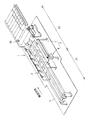
本実施形態の搬送装置1は、配達物を所定の条件(例えば配達区域ごと)によって区分けする図示しない配達物区分装置の下流端に設置される装置であり、その区分けされた配達物を配達物収納用ボックス等(以下、単にボックスともいう)に受け入れて、そのボックスを所定の保管場所まで搬送するための装置である。すなわち、本実施形態の搬送装置1は、図1に示すように、ボックスが搬送されるコンベアラインの一部を構成するものであり、当該コンベアラインの始端を担う装置である。
Below, the conveying apparatus 1 of embodiment of this invention is demonstrated.
The transport apparatus 1 according to the present embodiment is a device installed at a downstream end of a delivery sorting apparatus (not shown) that sorts deliveries according to predetermined conditions (for example, for each delivery area). It is an apparatus for receiving a storage box or the like (hereinafter also simply referred to as a box) and transporting the box to a predetermined storage location. That is, as shown in FIG. 1, the transport apparatus 1 according to the present embodiment constitutes a part of a conveyor line in which boxes are transported, and is an apparatus that bears the beginning of the conveyor line.

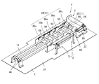
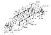
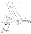
搬送装置1は、図1、2に示すように、搬送方向上流側の幅が細く、搬送方向中間から下流端にかけて幅が広い外観を呈しており、主に、ボックスの搬送に寄与する搬送部2と、ボックスの姿勢変更を可能とする物品受入機構3と、それらを支持する土台形成部5とで構成されている。より具体的には、本実施形態の搬送装置1は、幅狭長方形領域21と幅広長方形領域22に区分されており、幅広長方形領域22に物品受入機構3が配置されており、その幅広長方形領域22と幅狭長方形領域21とに跨るように搬送部2が配置されている。   As shown in FIGS. 1 and 2, the transport device 1 has a narrow width on the upstream side in the transport direction and a wide width from the middle in the transport direction to the downstream end. The transport unit mainly contributes to transport of the box. 2, an article receiving mechanism 3 that can change the posture of the box, and a base forming unit 5 that supports them. More specifically, the conveyance device 1 of the present embodiment is divided into a narrow rectangular region 21 and a wide rectangular region 22, and the article receiving mechanism 3 is arranged in the wide rectangular region 22, and the wide rectangular region The conveyance unit 2 is disposed so as to straddle 22 and the narrow rectangular region 21.

まず、土台形成部5から説明する。
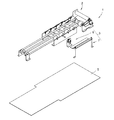
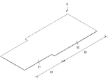
土台形成部5は、金属製の板体であり、幅狭長方形領域21の底壁を形成する幅狭底壁部31と、幅広長方形領域22の底壁を形成する幅広底壁部32とで構成されている。そして、土台形成部5は、幅狭底壁部31が、幅広底壁部32のいずれかの一辺であって、その一辺の中央に配置されており、当該幅狭底壁部31の長手側の辺が当該幅広底壁部32から張り出すように接続された形状である。なお、土台形成部5には、図示しないが、搬送部2や物品受入機構3の構成部品を固定するための複数の固定用孔が設けられている。
First, the base forming unit 5 will be described.
The base forming portion 5 is a metal plate, and includes a narrow bottom wall portion 31 that forms the bottom wall of the narrow rectangular region 21 and a wide bottom wall portion 32 that forms the bottom wall of the wide rectangular region 22. It is configured. The base forming portion 5 has the narrow bottom wall portion 31 which is one side of the wide bottom wall portion 32 and is arranged at the center of the one side, and the longitudinal side of the narrow bottom wall portion 31 These sides are connected so as to protrude from the wide bottom wall portion 32. Although not shown, the base forming unit 5 is provided with a plurality of fixing holes for fixing components of the transport unit 2 and the article receiving mechanism 3.

続いて、搬送部2について説明する。
搬送部2は、コンベアライン上に載置されたボックスを、搬送用ローラ11と搬送用ベルト12の双方で搬送できる構成である。そして、本実施形態は、搬送部2に1つの駆動源が設けられており、その駆動源によって、搬送用ローラ11と搬送用ベルト12の双方を駆動できる構成である。すなわち、搬送部2は、ローラ本体36に駆動源たるモータ37が内蔵されたモータ内蔵ローラ35及び5本の従動ローラ38とで構成された搬送用ローラ11と、2条の搬送用ベルト12と、搬送用ベルト12を懸架するための2つのプーリ40と、搬送用ローラ11及びプーリ40を支持する3種類の搬送用フレーム67、68、69を有する。
Next, the transport unit 2 will be described.
The transport unit 2 is configured to transport the box placed on the conveyor line by both the transport roller 11 and the transport belt 12. In this embodiment, the transport unit 2 is provided with a single drive source, and both the transport roller 11 and the transport belt 12 can be driven by the drive source. That is, the transport unit 2 includes a transport roller 11 including a motor built-in roller 35 in which a motor 37 serving as a driving source is built in a roller body 36 and five driven rollers 38, and two strips of the transport belt 12. And two pulleys 40 for suspending the conveying belt 12 and three types of conveying frames 67, 68, 69 for supporting the conveying roller 11 and the pulley 40.

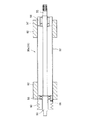
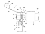
モータ内蔵ローラ35は、図6に示すように、ローラ本体36内にモータ37と減速機39が内蔵されたものが採用されている。すなわち、モータ内蔵ローラ35は、減速機39の出力軸45をローラ本体36の内面と係合させており、モータ37の回転力が減速機39で減速されてローラ本体36を回転させる構成である。   As shown in FIG. 6, the motor built-in roller 35 employs a roller body 36 in which a motor 37 and a speed reducer 39 are built. That is, the motor built-in roller 35 is configured such that the output shaft 45 of the speed reducer 39 is engaged with the inner surface of the roller body 36, and the rotational force of the motor 37 is decelerated by the speed reducer 39 to rotate the roller body 36. .

また、ローラ本体36の両端からは、支持軸46、47が突出している。すなわち、支持軸46、47は、図6に示すように、ローラ本体36の両端に装着された蓋部材48に、ローラ本体36の内外に渡って挿通されている。そして、2つの支持軸46、47はいずれも、蓋部材48よりもローラ本体36の内側に位置する軸受け50、51を介して、ローラ本体36に取り付けられている。そのため、ローラ本体36は、支持軸46、47に対して相対回転可能である。   Further, support shafts 46 and 47 protrude from both ends of the roller body 36. That is, as shown in FIG. 6, the support shafts 46 and 47 are inserted through the lid members 48 attached to both ends of the roller body 36 over the inside and outside of the roller body 36. The two support shafts 46 and 47 are both attached to the roller body 36 via bearings 50 and 51 located inside the roller body 36 with respect to the lid member 48. Therefore, the roller body 36 can rotate relative to the support shafts 46 and 47.

また、一方の支持軸47は、中空構造であり、その中空部内部に給電線60が挿通されている。すなわち、ローラ本体36の内部に配されたモータ37は、この給電線60を介して、外部から電力が供給される。
なお、ローラ本体36の軸線方向一方(図6の右側)の端部に装着された蓋部材48の表面には、駆動用ベルト59(図1、2)を係合させるための溝61が環状に設けられている。
One support shaft 47 has a hollow structure, and a power supply line 60 is inserted into the hollow portion. In other words, the motor 37 disposed inside the roller body 36 is supplied with electric power from the outside via the power supply line 60.
A groove 61 for engaging the driving belt 59 (FIGS. 1 and 2) is annular on the surface of the lid member 48 attached to one end of the roller body 36 in the axial direction (right side in FIG. 6). Is provided.

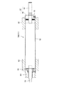
本実施形態の従動ローラ38は、図7に示すローラ本体52のみが回転し得る空転ローラ38aと、図8に示すローラ本体52とその軸線方向一方の端部に配された支持軸53が共に回転する軸一体型空転ローラ38bが採用されている。   The driven roller 38 according to the present embodiment includes an idle roller 38a that can rotate only the roller body 52 shown in FIG. 7, and a roller body 52 shown in FIG. 8 and a support shaft 53 disposed at one end in the axial direction thereof. A rotating shaft-integrated idling roller 38b is employed.

空転ローラ38aは、図7に示すように、ローラ本体52の中に、モータ等の駆動源を有さない構成である。また、ローラ本体52の両端には、軸線方向に突出した支持軸53、55が設けられている。すなわち、支持軸53、55は、ローラ本体52の両端に装着された蓋部材58に、ローラ本体52の内外に渡って挿通されている。そして、2つの支持軸53、55は、いずれも蓋部材58よりもローラ本体52の内側に位置する軸受け56、57を介して、ローラ本体52に取り付けられている。そのため、空転ローラ38aにおいては、ローラ本体52が支持軸53、55に対して相対回転可能である。
なお、空転ローラ38aの支持軸53、55は、一つの軸部材を構成する一部分であり、その軸部材の両端部分である。
As shown in FIG. 7, the idle roller 38 a has a configuration in which the roller body 52 does not have a drive source such as a motor. Support shafts 53 and 55 projecting in the axial direction are provided at both ends of the roller body 52. That is, the support shafts 53 and 55 are inserted through the lid members 58 attached to both ends of the roller body 52 over the inside and outside of the roller body 52. The two support shafts 53 and 55 are both attached to the roller main body 52 via bearings 56 and 57 located inside the roller main body 52 with respect to the lid member 58. Therefore, in the idle roller 38 a, the roller body 52 can rotate relative to the support shafts 53 and 55.
Note that the support shafts 53 and 55 of the idling roller 38a are part of one shaft member, and are both end portions of the shaft member.

また、本実施形態では、ローラ本体52の軸線方向両端の位置において、当該ローラ本体52よりも外径が大きい外筒体62が挿着されている。外筒体62は、ゴムや樹脂等により成形された軸線方向に貫通した構造体である。また、外筒体62は、ローラ本体52の軸線方向長さよりも、十分に短い長さ(本実施形態ではローラ本体52の1/4倍程度の長さ)に設計されている。
なお、ローラ本体52の軸線方向の端部に装着された蓋部材58の表面には、駆動用ベルト59(図1、2)を係合させるための溝63が環状に設けられている。
Further, in the present embodiment, the outer cylindrical body 62 having an outer diameter larger than that of the roller main body 52 is inserted at positions at both ends in the axial direction of the roller main body 52. The outer cylinder 62 is a structure that is formed of rubber, resin, or the like and penetrates in the axial direction. Further, the outer cylindrical body 62 is designed to have a length that is sufficiently shorter than the length in the axial direction of the roller body 52 (in this embodiment, about 1/4 times as long as the roller body 52).
A groove 63 for engaging the driving belt 59 (FIGS. 1 and 2) is provided in an annular shape on the surface of the lid member 58 attached to the end of the roller body 52 in the axial direction.

また、本実施形態では、従動ローラ38の1つとして、ローラ本体52の代わりに、中心軸65を備えた構造の空転ローラ38c(図1、2の右側に位置する従動ローラ38)が採用されているが、基本構造は前記した空転ローラ38aと同様であり、搬送用ベルト12を懸架するための懸架部66を有するという点だけが異なるため、説明を省略する。   In the present embodiment, as one of the driven rollers 38, an idle roller 38c (driven roller 38 located on the right side in FIGS. 1 and 2) having a central shaft 65 is employed instead of the roller body 52. However, the basic structure is the same as that of the idling roller 38a described above, and only the point that it has a suspension portion 66 for suspending the conveyor belt 12 is omitted.

軸一体型空転ローラ38bは、基本構造が前記した空転ローラ38aと同様であり、ローラ本体52の軸線方向一方(図8の右側)の支持軸43がローラ本体52と一体的に回転するという構造だけが異なるため、基本構造の説明は省略し、その異なる点に着目して説明する。   The shaft-integrated idling roller 38b has the same basic structure as the idling roller 38a described above, and has a structure in which one support shaft 43 in the axial direction of the roller body 52 (right side in FIG. 8) rotates integrally with the roller body 52. Since only the differences are described, the description of the basic structure will be omitted, and the description will focus on the different points.

すなわち、軸一体型空転ローラ38bは、ローラ本体52の軸線方向一方(図8の右側)の端部に、蓋部材44と支持軸43とが相対回転不能に接続された回転軸体42が装着された構成である。より具体的には、ローラ本体52の端部には、蓋部材44が装着され、さらにその蓋部材44の内側に一体的に接続された支持軸43が、ローラ本体52の内外に渡って挿着されている。そして、ローラ本体52と回転軸体42の一体性を向上させるべく、ローラ本体52の外側から蓋部材44に渡って固定ピン70が取り付けられている。一方、ローラ本体52の軸線方向他方(図8の左側)の端部に設けられた支持軸53は、前記したように、軸受け56を介して取り付けられている。これにより、軸一体型空転ローラ38bは、支持軸53以外の部分、つまりローラ本体52と蓋部材44及び支持軸43が一体的に回転する。   In other words, the shaft-integrated idling roller 38b has a rotating shaft body 42 in which the lid member 44 and the support shaft 43 are connected to each other so as not to rotate relative to each other (on the right side in FIG. 8) in the axial direction of the roller body 52. It is the structure which was made. More specifically, a lid member 44 is attached to the end of the roller body 52, and a support shaft 43 that is integrally connected to the inside of the lid member 44 is inserted inside and outside the roller body 52. It is worn. A fixing pin 70 is attached to the lid member 44 from the outside of the roller body 52 in order to improve the integrity of the roller body 52 and the rotating shaft body 42. On the other hand, the support shaft 53 provided at the other end (left side in FIG. 8) in the axial direction of the roller body 52 is attached via the bearing 56 as described above. As a result, the shaft-integrated idling roller 38b rotates at a portion other than the support shaft 53, that is, the roller body 52, the lid member 44, and the support shaft 43 integrally.

搬送用ベルト12は、公知の歯付ベルトであり、無端状に形成されたものが採用されている。
また、プーリ40は、公知のそれと同様であり、本体部71の中央に回転軸72が挿着されており、その回転軸72に対して、本体部71の相対回転を可能とするものである。
The conveyor belt 12 is a known toothed belt, and an endless belt is used.
Further, the pulley 40 is similar to a known one, and a rotation shaft 72 is inserted in the center of the main body 71, and the main body 71 can be rotated relative to the rotation shaft 72. .

3種類の搬送用フレーム67、68、69は、用途ごとに分類されており、いずれもほぼ同一の大きさ及び形状のものが対を成して形成されている。すなわち、本実施形態では、モータ内蔵ローラ35及び空転ローラ38cを支持する駆動用フレーム67と、空転ローラ38a及び軸一体型空転ローラ38bを支持する従動用フレーム68と、プーリ40を支持するプーリ用フレーム69とに分類されている。そして、いずれの搬送用フレーム67、68、68も、ほぼ同様の構造であり、土台形成部5に固定される底壁fと、搬送用ローラ11やプーリ40等を支持する側壁wとを有する構成である。   The three types of transfer frames 67, 68, and 69 are classified according to use, and all of them are formed in pairs with substantially the same size and shape. That is, in the present embodiment, a driving frame 67 that supports the motor built-in roller 35 and the idling roller 38c, a driven frame 68 that supports the idling roller 38a and the shaft-integrated idling roller 38b, and a pulley that supports the pulley 40. The frame 69 is classified. Each of the transport frames 67, 68, 68 has substantially the same structure, and has a bottom wall f fixed to the base forming portion 5 and a side wall w that supports the transport roller 11, the pulley 40, and the like. It is a configuration.

そして、本実施形態の搬送部2では、各搬送用フレーム67、68、69を、以下に示す順番で並べている。すなわち、搬送方向下流側から順番に、駆動用フレーム67、従動用フレーム68、プーリ用フレーム69を直列状に並べている。そして、それぞれのフレーム67、68、69の間に、モータ内蔵ローラ35、搬送用ローラ11、プーリ40のうちのいずれか1種あるいは2種の回転体を配置し、全ての回転体が同一の方向に回転し得るように固定されている。より詳細に説明すると、駆動用フレーム67には、上流側にモータ内蔵ローラ35が配置され、その下流側に隣接する位置に空転ローラ38cが配置されている。従動用フレーム68には、4つの従動ローラ38が並べられており、上流側から、空転ローラ(以下、第1空転ローラともいう)38a、軸一体型空転ローラ38b、空転ローラ(以下、第2空転ローラともいう)38a、空転ローラ(以下、第3空転ローラともいう)38aの順番で配列されている。また、プーリ用フレーム69には、2つのプーリ40がそれぞれの回転軸72の端部を対向させた姿勢で配されている。   And in the conveyance part 2 of this embodiment, each frame 67, 68, 69 for conveyance is arranged in the order shown below. That is, the driving frame 67, the driven frame 68, and the pulley frame 69 are arranged in series in order from the downstream side in the transport direction. And between each frame 67, 68, 69, one or two types of rotating bodies of the motor built-in roller 35, the conveying roller 11, and the pulley 40 are arranged, and all the rotating bodies are the same. It is fixed so that it can rotate in the direction. More specifically, in the driving frame 67, the motor built-in roller 35 is arranged on the upstream side, and the idling roller 38c is arranged at a position adjacent to the downstream side thereof. Four driven rollers 38 are arranged in the driven frame 68. From the upstream side, an idle roller (hereinafter also referred to as a first idle roller) 38a, a shaft-integrated idle roller 38b, and an idle roller (hereinafter referred to as a second idle roller). The idle rollers 38a and the idle rollers (hereinafter also referred to as third idle rollers) 38a are arranged in this order. The pulley frame 69 is provided with two pulleys 40 in such a posture that the end portions of the respective rotation shafts 72 are opposed to each other.

また、モータ内蔵ローラ35の動力を従動ローラ38に伝動するべく、隣接するローラ35、11同士を、駆動用ベルト59で懸架している。具体的には、搬送方向下流側から順番に、モータ内蔵ローラ35と空転ローラ38cに跨るように、1つの駆動用ベルト59が懸架され、その空転ローラ38cと第3空転ローラ38aに跨るように、別の1つの駆動用ベルト59が懸架され、第3空転ローラ38aと第2空転ローラ38aに跨るように、さらに別の1つの駆動用ベルト59が懸架され、第2空転ローラ38aと第1空転ローラ38aに跨るようにさらに別の1つの駆動用ベルト59が懸架されている。   Further, adjacent rollers 35 and 11 are suspended by a driving belt 59 in order to transmit the power of the motor built-in roller 35 to the driven roller 38. Specifically, one drive belt 59 is suspended so as to straddle the motor built-in roller 35 and the idling roller 38c in order from the downstream side in the transport direction, and straddle the idling roller 38c and the third idling roller 38a. Another drive belt 59 is suspended, and another drive belt 59 is suspended so as to straddle the third idle roller 38a and the second idle roller 38a, and the second idle roller 38a and the first idle roller 38a. Another one driving belt 59 is suspended so as to straddle the idling roller 38a.

そして、本実施形態では、モータ内蔵ローラ35の動作に連動させるべく、2条の搬送用ベルト12が、空転ローラ38cからプーリ40に渡るように懸架されている。より具体的には、搬送用ベルト12は、長手方向中途の部分が、空転ローラ38a及び軸一体型空転ローラ38bに装着された外筒体62よりも軸線方向内側の位置に配され、さらにその位置において各ローラ38a、38bの軸線に対して直交するように配されており、その状態で、空転ローラ38cの懸架部66とプーリ40の本体部71に懸架されている。このため、搬送用ベルト12は、空転ローラ38cを介して入力された動力によって、空転ローラ38cとプーリ40との間を環状に移動する。なお、搬送用ベルト12は、上方から載荷されていない状態においては、空転ローラ38a及び軸一体型空転ローラ38bには非接触であり、それらから若干離反した位置で移動を行う。   In this embodiment, the two conveying belts 12 are suspended from the idle roller 38 c to the pulley 40 so as to be interlocked with the operation of the motor built-in roller 35. More specifically, the conveying belt 12 is arranged in the middle in the longitudinal direction at a position on the inner side in the axial direction with respect to the outer cylindrical body 62 mounted on the idle roller 38a and the shaft-integrated idle roller 38b. In this position, the rollers 38a and 38b are arranged so as to be orthogonal to the axis of the rollers 38a and 38b. In this state, they are suspended by the suspension 66 of the idle roller 38c and the main body 71 of the pulley 40. For this reason, the conveyor belt 12 moves in an annular manner between the idle roller 38c and the pulley 40 by the power input via the idle roller 38c. In the state where the conveyor belt 12 is not loaded from above, the conveyor belt 12 is not in contact with the idle roller 38a and the shaft-integrated idle roller 38b, and moves at a position slightly separated from them.

続いて、物品受入機構3について説明する。
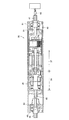
物品受入機構3は、コンベアライン上に載置されたボックスを一定方向に傾倒できる部分であり、図9、10に示すように、搬送部2から動力が入力される一次側伝達部6と、搬送部2の動力が一次側伝達部6を介して入力される二次側伝達部7とで構成されている。
Next, the article receiving mechanism 3 will be described.
The article receiving mechanism 3 is a part capable of tilting a box placed on the conveyor line in a certain direction, and as shown in FIGS. 9 and 10, a primary side transmission unit 6 to which power is input from the conveyance unit 2, The power of the transport unit 2 is configured by a secondary side transmission unit 7 to which the power is input via the primary side transmission unit 6.

一次側伝達部6は、クラッチ機能を有した回転方向規制手段16を備え、搬送部2から入力される動力の回転方向によって、外部への出力の可否を変更可能な部分である。そして、一次側伝達部6は、回転方向規制手段16に加えて、固定用軸受け13と、カム部材(カム構造体)15と、カム部材15に付勢力を付与する付勢部材17と、それらを支持する一次側支持部材18とを有する。   The primary side transmission unit 6 includes a rotation direction restricting unit 16 having a clutch function, and is a portion that can change whether to output to the outside according to the rotation direction of the power input from the transport unit 2. In addition to the rotation direction restricting means 16, the primary transmission unit 6 includes a fixing bearing 13, a cam member (cam structure) 15, a biasing member 17 that applies a biasing force to the cam member 15, and And a primary side support member 18 for supporting the.

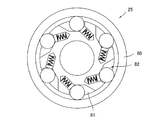
回転方向規制手段16は、公知のワンウェイクラッチたる回転規制部材25と、その回転規制部材25を収容する補助部材26とで構成されている。   The rotation direction restricting means 16 includes a rotation restricting member 25 that is a known one-way clutch and an auxiliary member 26 that accommodates the rotation restricting member 25.

回転規制部材25は、例えば、図11に示すような構造を有するものである。すなわち、回転規制部材25は、外輪80と内輪81との間にワンウェイクラッチ機構82が内蔵されたものである。これにより、回転規制部材25は、外輪80と内輪81が同期的に回転する「トルク伝達状態」と、外輪80と内輪81の相対回転を可能とする「トルク非伝達状態」とを相互に切り換え可能とする。具体的には、回転規制部材25は、外輪80及び内輪81の回転方向によって、「トルク伝達状態」と「トルク非伝達状態」が切り換わるものであり、外輪80が一方の方向(図11では時計回り方向)に回転する場合又は内輪81が他方の方向(図11では反時計回り方向)に回転する場合に「トルク伝達状態」となり、外輪80が他方の方向(図11では反時計回り方向)に回転する場合又は内輪81が一方の方向(図11では時計回り方向)に回転する場合に「トルク非伝達状態」となる。   For example, the rotation restricting member 25 has a structure as shown in FIG. In other words, the rotation restricting member 25 includes a one-way clutch mechanism 82 between the outer ring 80 and the inner ring 81. Thereby, the rotation restricting member 25 switches between a “torque transmission state” in which the outer ring 80 and the inner ring 81 rotate synchronously and a “torque non-transmission state” in which the outer ring 80 and the inner ring 81 can be relatively rotated. Make it possible. Specifically, the rotation restricting member 25 switches between the “torque transmission state” and the “torque non-transmission state” depending on the rotation direction of the outer ring 80 and the inner ring 81, and the outer ring 80 moves in one direction (in FIG. 11). When it rotates in the clockwise direction or when the inner ring 81 rotates in the other direction (counterclockwise in FIG. 11), it becomes “torque transmission state”, and the outer ring 80 moves in the other direction (counterclockwise in FIG. 11). ) Or when the inner ring 81 rotates in one direction (clockwise in FIG. 11).

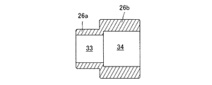
補助部材26は、回転規制部材25の外輪80と一体に回転する部分であり、異なる径の円筒体が直列状に並べられて、一体接続された構成である。具体的には、補助部材26は、径が小さい(大径筒部26bよりも径が小さい)小径筒部26aと、径が大きい(小径筒部26aよりも径が大きい)大径筒部26bとを有し、内部において、小径筒部26aと大径筒部26bとが連通した構造となっている。すなわち、補助部材26は、図12に示すように、小径筒部26aに軸挿通空間33が設けられ、大径筒部26bに回転規制部材配置空間34が設けられており、それらの空間33、34が互いに連通した構成である。   The auxiliary member 26 is a portion that rotates integrally with the outer ring 80 of the rotation restricting member 25, and has a configuration in which cylindrical bodies having different diameters are arranged in series and are integrally connected. Specifically, the auxiliary member 26 has a small-diameter cylindrical portion 26a having a small diameter (smaller than the large-diameter cylindrical portion 26b) and a large-diameter cylindrical portion 26b having a large diameter (larger than the small-diameter cylindrical portion 26a). In the inside, the small-diameter cylindrical portion 26a and the large-diameter cylindrical portion 26b communicate with each other. That is, as shown in FIG. 12, the auxiliary member 26 is provided with a shaft insertion space 33 in the small diameter cylindrical portion 26a and a rotation restricting member arrangement space 34 in the large diameter cylindrical portion 26b. 34 are configured to communicate with each other.

なお、本実施形態では、小径筒部26aの外径は、後述するカム部材15の回動孔23の開口径とほぼ同程度の大きさに設定され、大径筒部26bの内径は、前記した回転規制部材25の外径とほぼ同程度の大きさに設定されている。換言すれば、補助部材26は、小径筒部26aをカム部材15の回動孔23に嵌合でき、大径筒部26bに回転規制部材25を嵌合させることができるものである。   In the present embodiment, the outer diameter of the small-diameter cylindrical portion 26a is set to be approximately the same as the opening diameter of the rotation hole 23 of the cam member 15 described later, and the inner diameter of the large-diameter cylindrical portion 26b is The rotation restricting member 25 is set to a size that is approximately the same as the outer diameter. In other words, the auxiliary member 26 can fit the small diameter cylindrical portion 26a into the rotation hole 23 of the cam member 15 and fit the rotation regulating member 25 into the large diameter cylindrical portion 26b.

固定用軸受け13は、公知のベアリングであり、本実施形態では、搬送部2の軸一体型空転ローラ38bの支持軸43を支持するものとして使用されている。   The fixing bearing 13 is a known bearing, and is used as a support for the support shaft 43 of the shaft-integrated idling roller 38b of the transport unit 2 in this embodiment.

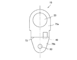
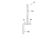
カム部材15は、二次側伝達部7に動力を出力する部分であり、基本構造が公知の板カムと同様のものが採用されている。すなわち、カム部材15は、図10に示すように、外観が板状体であり、回動中心と部材中心とが一致しない構造、つまり偏心した構造である。そして、本実施形態では、図13に示すように、正面視した形状がほぼ楕円を呈したカム部材15が採用されている。より詳細には、カム部材15は、正面視形状がほぼ楕円であると見た場合、回動中心たる回動孔23を長軸方向の一方に偏らせた配置にしている。すなわち、カム部材15は、回動孔23を基準に、長軸方向一方の端部までの距離が、他方の端部までの距離よりも長いあるいは短い構成である。   The cam member 15 is a portion that outputs power to the secondary transmission unit 7, and has the same basic structure as a known plate cam. That is, as shown in FIG. 10, the cam member 15 has a plate-like appearance, and has a structure in which the rotation center does not coincide with the member center, that is, an eccentric structure. In the present embodiment, as shown in FIG. 13, a cam member 15 having a substantially oval shape when viewed from the front is employed. More specifically, the cam member 15 is arranged such that the rotation hole 23 serving as the rotation center is biased to one side in the long axis direction when the front view shape is substantially elliptical. That is, the cam member 15 has a configuration in which the distance to one end in the long axis direction is longer or shorter than the distance to the other end with respect to the rotation hole 23.

また、カム部材15は、長軸方向の中途の位置において、部材厚方向に所定の角度(本実施形態では90°)で折り曲げた段部73が設けられている。そして、カム部材15は、図14に示すように、段部73を挟んだ両側の位置に、互いに平行な異なる平面部75a、75bが配されている。すなわち、本実施形態のカム部材15は、部材厚方向に立体的な構造である。そして、カム部材15には、平面部75aに対して、ほぼ直交方向に立設した立設部49が設けられている。この立設部49は、平面部75aの一部を切り込んで、その平面部75aに対して立ち上げた部分であり、後述する付勢部材17を係止する機能を有する。   Further, the cam member 15 is provided with a stepped portion 73 bent at a predetermined angle (90 ° in the present embodiment) in the member thickness direction at a midway position in the major axis direction. As shown in FIG. 14, the cam member 15 is provided with different plane portions 75 a and 75 b parallel to each other at positions on both sides of the stepped portion 73. That is, the cam member 15 of the present embodiment has a three-dimensional structure in the member thickness direction. The cam member 15 is provided with a standing portion 49 that is erected in a substantially orthogonal direction with respect to the flat portion 75a. The standing portion 49 is a portion formed by cutting a part of the flat portion 75a and rising with respect to the flat portion 75a, and has a function of locking an urging member 17 described later.

なお、本実施形態のカム部材15には、図9、10に示すように、長軸方向回動孔23と対向する側、具体的には平面部75b側に、二次側伝達部7への動力の伝達を円滑にするための補助輪76が設けられている。すなわち、カム部材15には、図13に示すように、平面部75bの部材厚方向に軸孔83が設けられており、その軸孔83を介して補助輪76が軸支されている。   As shown in FIGS. 9 and 10, the cam member 15 of the present embodiment has a side facing the long-axis direction rotation hole 23, specifically, on the flat surface portion 75 b side, to the secondary side transmission portion 7. Auxiliary wheels 76 are provided for smooth transmission of the power. That is, as shown in FIG. 13, the cam member 15 is provided with a shaft hole 83 in the member thickness direction of the flat portion 75 b, and the auxiliary wheel 76 is pivotally supported through the shaft hole 83.

付勢部材17は、公知のねじりコイルばね(トーションばね)であり、両端のアーム90a、90b同士の間に角度が形成されていないものが採用されている。すなわち、付勢部材17は、アーム90a、90bの延伸方向が同一であり、双方のアーム90a、90bを相対的に離反するように変位させれば、両者が相対的に近接する方向に反力が発生する。   The urging member 17 is a known torsion coil spring (torsion spring), and one having no angle formed between the arms 90a, 90b at both ends is employed. That is, in the urging member 17, the extending directions of the arms 90a and 90b are the same, and if both the arms 90a and 90b are displaced so as to be relatively separated from each other, the reaction force is exerted in the direction in which the both are relatively close to each other. Occurs.

一次側支持部材18は、ほぼ「L」字型の外観を呈しており、底壁kと側壁jとで構成されている。そして、側壁jには、搬送部2の軸一体型空転ローラ38bの支持軸43が挿通される挿通部77と、付勢部材17のアーム90の一方を保持する保持部78が設けられている。挿通部77は、側壁jの上端に設けられた、「U」字型を呈した切欠きである。また、保持部78は、側壁jの一方の面に配されており、その面からほぼ直交する方向に立設した部分である。なお、本実施形態では、保持部78は、側壁jを切り込んで立設した立設部78a、78bを2つ組み合わせて形成されている(図10、16)。   The primary side support member 18 has a substantially “L” -shaped appearance, and includes a bottom wall k and a side wall j. The side wall j is provided with an insertion portion 77 through which the support shaft 43 of the shaft-integrated idling roller 38b of the transport portion 2 is inserted, and a holding portion 78 that holds one of the arms 90 of the urging member 17. . The insertion portion 77 is a notch having a “U” shape provided at the upper end of the side wall j. Further, the holding portion 78 is disposed on one surface of the side wall j, and is a portion erected in a direction substantially orthogonal to the surface. In the present embodiment, the holding portion 78 is formed by combining two standing portions 78a and 78b that are erected by cutting the side wall j (FIGS. 10 and 16).

そして、一次側伝達部6では、図9に示すように、一次側支持部材18の側壁jを部材厚方向に挟むように、他の部材が配されている。すなわち、一次側支持部材18の保持部78が位置する側の面には、その面から離反する方向に向けて、付勢部材17、カム部材15、回転方向規制手段16の順番で配され、その面の裏面側には、固定用軸受け13が配されている。具体的には、一次側伝達部6は、一次側支持部材18の挿通部77と連通するように、固定用軸受け13と、付勢部材17のコイル部と、カム部材15の回動孔23と、回転方向規制手段16における補助部材26の空間33、34及び回転規制部材25が配されている。   And in the primary side transmission part 6, as shown in FIG. 9, the other member is distribute | arranged so that the side wall j of the primary side support member 18 may be pinched | interposed into a member thickness direction. That is, the biasing member 17, the cam member 15, and the rotation direction regulating means 16 are arranged in this order on the surface on the side where the holding portion 78 of the primary side support member 18 is located, in a direction away from the surface. A fixing bearing 13 is disposed on the back side of the surface. Specifically, the primary transmission portion 6 is connected to the insertion portion 77 of the primary support member 18 so as to communicate with the fixing bearing 13, the coil portion of the biasing member 17, and the rotation hole 23 of the cam member 15. The spaces 33 and 34 of the auxiliary member 26 and the rotation restricting member 25 in the rotation direction restricting means 16 are arranged.

より詳細には、回転方向規制手段16の補助部材26は、図15に示すように、小径筒部26aをカム部材15側に向けた姿勢にされており、その小径筒部26aの外周部分にカム部材15と付勢部材17が装着されている。そのため、厳密に言うと、付勢部材17、カム部材15、回転方向規制手段16は、この順番で配されているとは言えないが、回転方向規制手段16の主たる構成部品たる回転規制部材25が、その順番を満たすため、付勢部材17、カム部材15、回転方向規制手段16の順番で並んでいることとする。   More specifically, as shown in FIG. 15, the auxiliary member 26 of the rotation direction restricting means 16 has a posture in which the small-diameter cylindrical portion 26a faces the cam member 15 side, and an outer peripheral portion of the small-diameter cylindrical portion 26a. A cam member 15 and a biasing member 17 are mounted. Therefore, strictly speaking, the urging member 17, the cam member 15, and the rotation direction restricting means 16 cannot be said to be arranged in this order, but the rotation restricting member 25 which is a main component of the rotation direction restricting means 16. However, in order to satisfy the order, the biasing member 17, the cam member 15, and the rotation direction regulating means 16 are arranged in this order.

そして、このような状態において、付勢部材17のアーム90が、カム部材15と一次側支持部材18に係止あるいは係合するように配されている。すなわち、カム部材15を回動孔23の真下に補助輪76が位置するような姿勢にして(以下、待機状態という)、その状態で、付勢部材17を、図16に示すように、一方のアーム90aをカム部材15の立設部49に係止させると共に、他方のアーム90bを一次側支持部材18の保持部78に係合させている。換言すれば、付勢部材17は、待機状態のカム部材15が回動孔23を基準に所定の方向に回動すれば、アーム90a、90bが相対的に離反し、カム部材15が前記方向と相反する方向に回動すれば、アーム90a、90bが相対的に近接する配置である。   In such a state, the arm 90 of the urging member 17 is disposed so as to be locked or engaged with the cam member 15 and the primary side support member 18. That is, the cam member 15 is set in a posture such that the auxiliary wheel 76 is positioned directly below the rotation hole 23 (hereinafter referred to as a standby state), and in this state, the urging member 17 is moved as shown in FIG. The other arm 90 b is engaged with the holding portion 78 of the primary side support member 18, and the other arm 90 b is engaged with the standing portion 49 of the cam member 15. In other words, the biasing member 17 is configured such that when the cam member 15 in the standby state is rotated in a predetermined direction with reference to the rotation hole 23, the arms 90a and 90b are relatively separated from each other, and the cam member 15 is If the arms 90a and 90b are rotated in the opposite direction, the arms 90a and 90b are relatively close to each other.

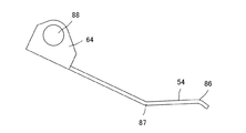
一方、二次側伝達部7は、図10に示すように、所定の大きさを有した平面部54を備え、その平面部54によって、コンベアライン上のボックス等を実際に傾倒させる部分である。すなわち、二次側伝達部7は、平面部54を有する回動部材27と、その回動部材27を支持する二次側支持部材28とを有する。   On the other hand, as shown in FIG. 10, the secondary side transmission unit 7 includes a flat part 54 having a predetermined size, and the flat part 54 is a part that actually tilts a box or the like on the conveyor line. . That is, the secondary side transmission unit 7 includes a rotating member 27 having a flat surface portion 54 and a secondary side support member 28 that supports the rotating member 27.

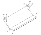
回動部材27は、主要部分が金属製の1枚の板体で形成されており、その板部材を所定の位置で折り曲げて屈曲形状に形成した部材である。具体的には、回動部材27は、長方形状の板体を屈曲した部材であり、短手方向に異なる2箇所で折り曲げられている。より詳細には、短手方向に異なる2箇所の折曲部86、87のうちの1つは、短手方向一方の端部寄りに配され(端部側折曲部86)、残りの1つは、その端部側折曲部86よりも短手方向中央寄りに配されている(中央側折曲部87)。そして、その回動部材27における2箇所の位置では、互いに異なる方向に折り曲げると共に、その折り曲げの角度は、いずれも優角及び劣角側が鈍角に設定されている。
なお、本実施形態では、端部側折曲部86と中央側折曲部87との間を平面部54としている。
The rotating member 27 is a member that has a main portion formed of a single metal plate, and is bent into a bent shape at a predetermined position. Specifically, the rotating member 27 is a member obtained by bending a rectangular plate, and is bent at two different locations in the short direction. More specifically, one of the two bent portions 86 and 87 different in the short direction is arranged near one end in the short direction (end side bent portion 86), and the remaining one The one is arranged closer to the center in the lateral direction than the end side bent portion 86 (center side bent portion 87). And in two positions in the rotation member 27, it bends in a mutually different direction, and the angle of the bending is set to the obtuse angle and the dominant angle and the minor angle side.
In the present embodiment, the flat portion 54 is formed between the end side bent portion 86 and the center side bent portion 87.

また、回動部材27には、短手方向他方の端部側(端部側折曲部86の位置と対向する端部側)に、一対の軸保持部64が設けられている。そして、その一対の軸保持部64は、回動部材27の長手方向両端に設けられ、回動軸91が挿通される孔88を向き合わせて配されている。
なお、回動軸91は、断面形状が円形の棒状部材であり、回動部材27の長手方向長さと同等あるいは若干大きい長さである。
In addition, the rotation member 27 is provided with a pair of shaft holding portions 64 on the other end side in the short side direction (the end side facing the position of the end side bent portion 86). The pair of shaft holding portions 64 are provided at both ends in the longitudinal direction of the rotating member 27, and are arranged with the holes 88 through which the rotating shaft 91 is inserted facing each other.
The rotating shaft 91 is a rod-shaped member having a circular cross-sectional shape, and has a length that is equal to or slightly larger than the length of the rotating member 27 in the longitudinal direction.

二次側支持部材28は、同一の大きさ及び形状のものが対をなして形成されたものであり、対をなすいずれの部材も、ほぼ「L」字型の外観を呈しており、底壁qと側壁rとで構成されている。そして、側壁rには、回動軸91を回動可能に支持する孔99が設けられている。   The secondary side support members 28 are formed of a pair having the same size and shape, and each of the paired members has a substantially “L” -shaped appearance, It consists of a wall q and a side wall r. The side wall r is provided with a hole 99 that rotatably supports the rotation shaft 91.

そして、二次側伝達部7では、図9に示すように、二次側支持部材28の孔99と、回動部材27の孔88とを連通させた状態にして、回動軸91が挿通されている。すなわち、二次側伝達部7では、図15に示すように、回動部材27が回動軸91を基準に回動し得る配置にされている。   As shown in FIG. 9, in the secondary side transmission unit 7, the rotation shaft 91 is inserted with the hole 99 of the secondary support member 28 and the hole 88 of the rotation member 27 communicating with each other. Has been. That is, in the secondary side transmission part 7, as shown in FIG. 15, the rotation member 27 is arranged so as to be rotatable with respect to the rotation shaft 91.

次に、本実施形態の搬送装置1における各部材の位置関係について説明する。
本実施形態の搬送装置1は、前述したように、配達物を区分けする配達物区分装置の下流端に設置される装置であり、その区分けされた配達物をボックスを用いて受け入れて、そのボックス(以下、配達物が導入されたボックスを物品という)を所定の保管場所まで搬送するコンベアラインの一部を形成している。そして、この搬送装置1は、物品の搬送方向上流側に幅狭長方形領域21を配置し、その下流側に幅広長方形領域22を配置している。
Next, the positional relationship of each member in the transport apparatus 1 of this embodiment will be described.
As described above, the transport apparatus 1 according to the present embodiment is an apparatus installed at the downstream end of the delivery sorting apparatus that sorts the delivery, and receives the sorted delivery using a box, and the box. A part of a conveyor line that conveys a box (hereinafter referred to as a box in which a delivery item is introduced) to a predetermined storage location is formed. And this conveying apparatus 1 has arrange | positioned the narrow rectangular area | region 21 in the conveyance direction upstream of articles | goods, and has arrange | positioned the wide rectangular area | region 22 in the downstream.

そして、図1に示すように、その2つの領域21、22に跨るように、搬送部2が配置されている。具体的には、搬送部2は、幅狭長方形領域21の張出端部側に、プーリ40を取り付けたプーリ用フレーム69を配して土台形成部5に固定し、幅広長方形領域22であって、幅狭長方形領域21との境界近傍に、4つの従動ローラ38を取り付けた従動用フレーム68を配して土台形成部5に固定し、その下流側の位置に、1つの従動ローラ38及び1つのモータ内蔵ローラ35を取り付けた駆動用フレーム67を配して土台形成部5に固定している。なお、上記したように、空転ローラ38cとプーリ40とに渡って、搬送用ベルト12が環状に懸架されている。   And as shown in FIG. 1, the conveyance part 2 is arrange | positioned so that the two area | regions 21 and 22 may be straddled. Specifically, the transport unit 2 has a pulley frame 69 to which a pulley 40 is attached arranged on the projecting end side of the narrow rectangular region 21 and is fixed to the base forming unit 5. Thus, a driven frame 68 having four driven rollers 38 attached thereto is arranged in the vicinity of the boundary with the narrow rectangular region 21 and fixed to the base forming portion 5, and one driven roller 38 and A driving frame 67 to which one motor built-in roller 35 is attached is arranged and fixed to the base forming portion 5. As described above, the conveying belt 12 is suspended in an annular shape across the idle roller 38 c and the pulley 40.

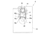
また、幅広長方形領域22には、搬送部2の搬送方向に直交する位置に、物品受入機構3が配置されている。具体的には、物品受入機構3は、一次側伝達部6を、軸一体型空転ローラ38bの支持軸43に接続される位置に配し、二次側伝達部7を、一次側伝達部6から出力される動力が入力される位置に配している。より詳細に説明すると、図15に示すように、一次側伝達部6は、軸一体型空転ローラ38bの支持軸43によって支持される位置に配され、その支持軸43の基端側から、固定用軸受け13、一次側支持部材18、付勢部材17、カム部材15、回転方向規制手段16の順番で並べられている。   In the wide rectangular region 22, the article receiving mechanism 3 is disposed at a position orthogonal to the transport direction of the transport unit 2. Specifically, in the article receiving mechanism 3, the primary side transmission unit 6 is arranged at a position connected to the support shaft 43 of the shaft-integrated idling roller 38b, and the secondary side transmission unit 7 is connected to the primary side transmission unit 6. It is arranged at the position where the power output from is input. More specifically, as shown in FIG. 15, the primary side transmission unit 6 is disposed at a position supported by the support shaft 43 of the shaft-integrated idling roller 38 b, and is fixed from the base end side of the support shaft 43. The bearings 13, the primary support member 18, the biasing member 17, the cam member 15, and the rotation direction restricting means 16 are arranged in this order.

そして、その一次側伝達部6のカム部材15から動力を受け得る位置に、二次側伝達部7の回動部材27が配されている。すなわち、図15に示すように、回動部材27は、回動基点となる軸保持部64が、一次側伝達部6よりも上方の位置に配され、さらに回動部材27の平面部54が、一次側伝達部6のほぼ真上に存在するように配されている。   A rotating member 27 of the secondary transmission unit 7 is disposed at a position where the power can be received from the cam member 15 of the primary transmission unit 6. That is, as shown in FIG. 15, in the rotating member 27, the shaft holding portion 64 serving as a rotation base point is disposed at a position above the primary side transmitting portion 6, and the flat portion 54 of the rotating member 27 is further provided. The primary side transmission unit 6 is arranged so as to exist almost directly above.

ここで、本実施形態では、回動部材27が搬送部2の動作を弊害しないように、回動部材27の先端側の高さ位置を一定以下に至らせない図示しないストッパが設けられている。そのため、回動部材27が前記ストッパによって規制されている状態においては、回動部材27の平面部54は、ほぼ水平状態を維持する。すなわち、回動部材27と一次側伝達部6は、一次側伝達部6から動力が入力されない状態においては、回動部材27の平面部54の垂直投影面内に、一次側伝達部6がほぼ存在する関係を維持する(以下、この状態を待機状態という)。   Here, in the present embodiment, a stopper (not shown) that does not bring the height position of the distal end side of the rotating member 27 below a certain level is provided so that the rotating member 27 does not adversely affect the operation of the transport unit 2. . Therefore, in a state where the rotating member 27 is regulated by the stopper, the flat surface portion 54 of the rotating member 27 is maintained in a substantially horizontal state. In other words, the rotation member 27 and the primary side transmission unit 6 are configured so that the primary side transmission unit 6 is substantially within the vertical projection plane of the flat surface portion 54 of the rotation member 27 when no power is input from the primary side transmission unit 6. An existing relationship is maintained (hereinafter, this state is referred to as a standby state).

次に、搬送装置1の動作について説明する。
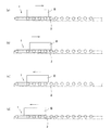
本実施形態における搬送装置1は、コンベアライン上に載置されたボックスBに配達物を受け入れるべく、当該ボックスBを傾倒し、その後、配達物が導入されたボックスB(以下、配達物の有無に関わらず単にボックスBという)を下流に向けて搬送するものである。すなわち、搬送装置1は、幅狭長方形領域21に配された図示しない在荷センサ等によって、自己の装置にボックスBが載置されたことが確認されれば、搬送部2を起動して、当該ボックスBを幅広長方形領域22側に搬送する初期搬送動作が実施される。
Next, the operation of the transport device 1 will be described.
In the present embodiment, the transport apparatus 1 tilts the box B so as to receive the delivery item in the box B placed on the conveyor line, and then the box B into which the delivery item is introduced (hereinafter, the presence or absence of the delivery item). Regardless of whether it is simply referred to as box B). That is, the conveying device 1 activates the conveying unit 2 when it is confirmed that the box B is placed on its own device by an unillustrated load sensor or the like arranged in the narrow rectangular region 21, An initial transport operation for transporting the box B to the wide rectangular region 22 side is performed.

より具体的には、この初期搬送動作が実施されると、モータ内蔵ローラ35は、モータ37を正回転方向に回転し、ローラ本体36を支持軸46、47を中心に正回転方向に回転させる。すると、搬送部2の従動ローラ38にその回転力が伝動されて、ローラ本体52が正回転方向に回転すると共に、搬送用ベルト12が正回転方向に移動する。これにより、図18(a)に示すように、ボックスBが搬送方向下流側、具体的には幅狭長方形領域21から幅広長方形領域22に向けて搬送される。そして、初期搬送動作では、図18(b)に示すように、幅広長方形領域22に搬送されたボックスBを、当該ボックスBの先頭が幅広長方形領域22の下流端に至る程度まで移動する。そして、幅広長方形領域22の所定の場所に配された図示しない在荷センサ等によって、ボックスBの搬送が確認されれば、モータ内蔵ローラ35の駆動を停止する。   More specifically, when this initial conveying operation is performed, the motor built-in roller 35 rotates the motor 37 in the forward rotation direction, and rotates the roller body 36 in the forward rotation direction around the support shafts 46 and 47. . Then, the rotational force is transmitted to the driven roller 38 of the transport unit 2 so that the roller body 52 rotates in the forward rotation direction and the transport belt 12 moves in the forward rotation direction. Thereby, as shown in FIG. 18A, the box B is transported downstream in the transport direction, specifically, from the narrow rectangular region 21 toward the wide rectangular region 22. In the initial transport operation, as shown in FIG. 18B, the box B transported to the wide rectangular area 22 is moved to the extent that the top of the box B reaches the downstream end of the wide rectangular area 22. And if conveyance of the box B is confirmed by the unillustrated load sensor etc. which were arrange | positioned in the predetermined place of the wide rectangular area | region 22, the drive of the motor built-in roller 35 will be stopped.

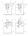
一方、このときの物品受入機構3の動作に注目すると、一次側伝達部6は、軸一体型空転ローラ38bを介して、モータ内蔵ローラ35の回転力が間接的に入力される。すなわち、一次側伝達部6の回転方向規制手段16には、ボックスBを下流側に向けて搬送する正回転方向の回転力が入力される。そして、このとき、回転方向規制手段16のワンウェイクラッチ機能が作用する。
なお、本実施形態においては、回転方向規制手段16における回転規制部材25の内輪81が正回転方向(時計回り方向)に回転する際に、「トルク非伝達状態」となり、その内輪81が逆回転方向(反時計回り方向)に回転する際に、「トルク伝達状態」となるものとする。
On the other hand, paying attention to the operation of the article receiving mechanism 3 at this time, the rotational force of the motor built-in roller 35 is indirectly input to the primary side transmission unit 6 via the shaft-integrated idling roller 38b. In other words, the rotational force in the normal rotational direction that conveys the box B toward the downstream side is input to the rotational direction regulating means 16 of the primary side transmission unit 6. At this time, the one-way clutch function of the rotation direction restricting means 16 acts.
In the present embodiment, when the inner ring 81 of the rotation restricting member 25 in the rotation direction restricting means 16 rotates in the forward rotation direction (clockwise direction), the “torque non-transmitting state” occurs, and the inner ring 81 rotates in the reverse direction. When rotating in the direction (counterclockwise direction), the “torque transmission state” is assumed.

すなわち、初期搬送動作では、一次側伝達部6に入力される動力の回転方向が正回転方向であるため、回転方向規制手段16が「トルク非伝達状態」となり、外部への出力が遮断される。すなわち、搬送装置1が初期搬送動作を行っている間は、図19(a)、(b)に示すように、回転方向規制手段16の回転規制部材25の外輪80は回転することはなく、それに接続されたカム部材15は待機状態を維持する。また同時に、二次側伝達部7に対しても、動力が入力されることがないため、図20(a)、(b)に示すように、回動部材27は待機状態を維持する。
したがって、本実施形態では、モータ内蔵ローラ35が正回転方向に回転制御されている間は、ボックスBが物品受入機構3によって、傾倒させられることはない。
That is, in the initial transfer operation, the rotation direction of the power input to the primary transmission unit 6 is the positive rotation direction, so the rotation direction restricting means 16 is in the “torque non-transmission state” and the output to the outside is shut off. . That is, while the transfer device 1 is performing the initial transfer operation, the outer ring 80 of the rotation restricting member 25 of the rotation direction restricting means 16 does not rotate as shown in FIGS. The cam member 15 connected thereto maintains the standby state. At the same time, since no power is input to the secondary transmission unit 7, as shown in FIGS. 20A and 20B, the rotating member 27 maintains the standby state.
Therefore, in the present embodiment, the box B is not tilted by the article receiving mechanism 3 while the motor built-in roller 35 is controlled to rotate in the forward rotation direction.

そして、初期搬送動作によりボックスBが所定の位置に至ると、ボックスBを傾倒させるべく、受入動作を実行する。受入動作が実行されると、モータ内蔵ローラ35のモータ37を、逆回転方向に回転するように駆動する。すなわち、受入動作では、モータ内蔵ローラ35の回転方向が、初期搬送動作の際の回転方向と逆方向に制御される。これにより、モータ内蔵ローラ35のローラ本体36及び従動ローラ38のローラ本体52が逆回転方向に回転すると共に、搬送用ベルト12が逆回転方向に移動する。したがって、ボックスBは、図19(c)に示すように、搬送方向上流側、具体的には幅広長方形領域22から幅狭長方形領域21に向かうように搬送される。そして、受入動作では、図19(d)に示すように、そのボックスBを物品受入機構3と隣接し得る程度の位置で停止させる。このとき、本実施形態では、モータ内蔵ローラ35を、所定のパルス数、具体的には、軸一体型空転ローラ38bを半回転させることができるパルス数だけ駆動する。   Then, when the box B reaches a predetermined position by the initial transport operation, the receiving operation is executed to tilt the box B. When the receiving operation is executed, the motor 37 of the motor built-in roller 35 is driven to rotate in the reverse rotation direction. That is, in the receiving operation, the rotation direction of the motor built-in roller 35 is controlled in the direction opposite to the rotation direction in the initial conveying operation. As a result, the roller main body 36 of the motor built-in roller 35 and the roller main body 52 of the driven roller 38 rotate in the reverse rotation direction, and the conveying belt 12 moves in the reverse rotation direction. Therefore, as shown in FIG. 19C, the box B is transported upstream in the transport direction, specifically, from the wide rectangular region 22 toward the narrow rectangular region 21. Then, in the receiving operation, as shown in FIG. 19 (d), the box B is stopped at a position where it can be adjacent to the article receiving mechanism 3. At this time, in the present embodiment, the motor built-in roller 35 is driven by a predetermined number of pulses, specifically, the number of pulses that can rotate the shaft-integrated idling roller 38b halfway.

そして、前記同様、このときの物品受入機構3の動作に注目すると、一次側伝達部6は、軸一体型空転ローラ38bを介して、間接的に逆回転方向の回転力が入力される。すなわち、受入動作では、前記したように、モータ内蔵ローラ35を逆回転方向に回転するため、回転方向規制手段16は「トルク伝達状態」となり、図20(c)に示すように、回転方向規制手段16の回転規制部材25の外輪80及び補助部材26が回転して、カム部材15を回動させる。そして、カム部材15が、図20(d)に示す待機状態からほぼ180°回転した位置に至ると、回動動作が停止される。すなわち、カム部材15は、駆動制御されるモータ内蔵ローラ35の前記所定のパルス数だけ回動して、一次側受入状態となる。   As noted above, paying attention to the operation of the article receiving mechanism 3 at this time, the primary-side transmission unit 6 is indirectly input with the rotational force in the reverse rotation direction via the shaft-integrated idling roller 38b. That is, in the receiving operation, as described above, since the motor built-in roller 35 is rotated in the reverse rotation direction, the rotation direction restricting means 16 is in the “torque transmission state”, and as shown in FIG. The outer ring 80 and the auxiliary member 26 of the rotation restricting member 25 of the means 16 rotate to rotate the cam member 15. Then, when the cam member 15 reaches a position rotated approximately 180 ° from the standby state shown in FIG. That is, the cam member 15 is rotated by the predetermined number of pulses of the motor-incorporated roller 35 that is driven and controlled, and enters the primary-side receiving state.

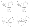
そして、カム部材15の回動動作に伴って、一次側伝達部6から二次側伝達部7への動力の入力が行われる。すなわち、図21(c)に示すように、カム部材15の先端側が、回動動作によって所定の高さに至ることで、その先端側に設けられた補助輪76が、回動部材27の下面側に当接し、二次側伝達部7に動力が出力される。   As the cam member 15 rotates, power is input from the primary transmission unit 6 to the secondary transmission unit 7. That is, as shown in FIG. 21 (c), when the tip end side of the cam member 15 reaches a predetermined height by the turning operation, the auxiliary wheel 76 provided on the tip end side of the tip end side of the turning member 27 Power is output to the secondary transmission unit 7.

より具体的には、回動部材27は、カム部材15によって、平面部54が上方に向けて押し上げられて、回動軸91を基点として回動する。そして、回動部材27は、図21(d)に示すように、平面部54が水平面に対して所定の角度に至るまで、換言すれば、中央側折曲部87と軸保持部64に跨った平面がほぼ水平状態に至るまで回動する。これにより、回動部材27は、平面部54を含む先端側が、搬送部2の搬送面よりも上部に露出した状態(以下、二次側受入状態という)となる。その結果、図21(c)、(d)に示すように、搬送面よりも上部に露出した回動部材27が、ボックスBを傾倒する。
その後、物品受入機構3において、搬送部2から出力される動力が二次側伝達部7に入力されなくなれば、カム部材15が、付勢部材17の付勢力によって、待機状態まで戻り、ボックスBを通常の姿勢に戻す。
More specifically, the rotating member 27 rotates about the rotating shaft 91 as the flat surface portion 54 is pushed upward by the cam member 15. Then, as shown in FIG. 21 (d), the rotating member 27 straddles the center side bent portion 87 and the shaft holding portion 64 until the flat portion 54 reaches a predetermined angle with respect to the horizontal plane. Rotate until the flat surface is almost horizontal. Thereby, the rotation member 27 is in a state where the distal end side including the flat portion 54 is exposed above the transport surface of the transport unit 2 (hereinafter referred to as a secondary side receiving state). As a result, as shown in FIGS. 21C and 21D, the rotating member 27 exposed above the transport surface tilts the box B.
Thereafter, in the article receiving mechanism 3, when the power output from the transport unit 2 is not input to the secondary transmission unit 7, the cam member 15 returns to the standby state by the biasing force of the biasing member 17, and the box B Return to normal posture.

以上のように、本実施形態では、搬送部2の駆動力を物品受入機構3に共用し、通常と異なる搬送、つまりボックスBを上流に向けて流す搬送制御を行った場合に、搬送部2上のボックスBを傾倒することができるため、従来の搬送装置と同様の搬送機能を確保しつつも、従来よりも合理的に物品受入機能を発揮させることができる。そして、モータ数の削減に伴って、製造コストの削減を図ることができる。   As described above, in this embodiment, when the driving force of the transport unit 2 is shared by the article receiving mechanism 3 and transport control different from normal, that is, transport control in which the box B flows upstream is performed, the transport unit 2 Since the upper box B can be tilted, the article receiving function can be exhibited more rationally than before while securing the same transport function as that of the conventional transport device. And the reduction in manufacturing cost can be aimed at with the reduction in the number of motors.

また、本実施形態によれば、搬送部2と物品受入機構3の双方に、個別に駆動源を用意する必要がないため、従来の搬送装置のように、個別のドライバーを必要としない。その結果、本実施形態では、従来のように、構造が煩雑化することがない。   Moreover, according to this embodiment, since it is not necessary to prepare a drive source separately in both the conveyance part 2 and the goods reception mechanism 3, a separate driver is not required like the conventional conveying apparatus. As a result, in the present embodiment, the structure is not complicated as in the prior art.

上記実施形態では、一次側伝達部6と二次側伝達部7とを備えた物品受入機構3を採用した構成を示したが、本発明はこれに限定されず、一次側伝達部6のみで構成された物品受入機構を用いても構わない。この場合、カム部材15が、直接的に、ボックスBを傾倒姿勢にすることができる。   In the said embodiment, although the structure which employ | adopted the goods acceptance mechanism 3 provided with the primary side transmission part 6 and the secondary side transmission part 7 was shown, this invention is not limited to this, Only the primary side transmission part 6 is shown. A configured article receiving mechanism may be used. In this case, the cam member 15 can directly place the box B in a tilted posture.

上記実施形態では、従動ローラ38を介して、搬送部2の駆動力を物品受入機構3に伝達する構成を示したが、本発明はこれに限定されず、モータ内蔵ローラ35から直接、物品受入機構3に伝達する構成であっても構わない。   In the above-described embodiment, the configuration in which the driving force of the conveying unit 2 is transmitted to the article receiving mechanism 3 via the driven roller 38 is shown, but the present invention is not limited to this, and the article receiving is directly performed from the motor built-in roller 35. It may be configured to transmit to the mechanism 3.

上記実施形態では、ワンウェイクラッチ機構を備えた回転方向規制手段16を採用した構成を示したが、本発明はこれに限定されず、ラチェット機構を備えた回転方向規制手段を採用しても構わない。   In the above-described embodiment, the configuration in which the rotation direction restricting means 16 including the one-way clutch mechanism is employed is shown. However, the present invention is not limited to this, and the rotation direction restricting means including the ratchet mechanism may be employed. .

上記実施形態では、搬送用ローラ11だけでなく、搬送用ベルト12を備えた搬送部2を採用した構成を示したが、本発明はこれに限定されず、搬送用ローラ11のみを備えた構成であっても構わない。また、搬送用ローラ11を構成する従動ローラ38を5本用いた構成を示したが、4本以下あるいは6本以上の従動ローラ38を備えた構成であっても構わない。   In the above-described embodiment, the configuration in which the conveyance unit 2 including the conveyance belt 12 as well as the conveyance roller 11 is employed has been described. However, the present invention is not limited thereto, and the configuration includes only the conveyance roller 11. It does not matter. Further, although the configuration using five driven rollers 38 constituting the conveying roller 11 is shown, a configuration including four or less driven rollers 38 or six or more driven rollers 38 may be used.

1 搬送装置
2 搬送部
3 物品受入機構
5 土台形成部
6 一次側伝達部
7 二次側伝達部
11 搬送用ローラ
15 カム部材(カム構造体)
16 回転方向規制手段
17 付勢部材(付勢手段)
25 回転規制部材
27 回動部材
35 モータ内蔵ローラ
37 モータ(駆動源)
38 従動ローラ
54 平面部
82 ワンウェイクラッチ機構
B ボックス
DESCRIPTION OF SYMBOLS 1 Conveyance apparatus 2 Conveyance part 3 Article acceptance mechanism 5 Base formation part 6 Primary side transmission part 7 Secondary side transmission part 11 Roller 15 for conveyance 15 Cam member (cam structure)
16 Rotation direction restricting means 17 Energizing member (urging means)
25 Rotation restriction member 27 Rotation member 35 Motor built-in roller 37 Motor (drive source)
38 Follower roller 54 Flat surface part 82 One-way clutch mechanism B Box

Claims (5)

物品を搬送する搬送部と、当該搬送部に物品が載置される前後のタイミングで姿勢変更が可能な物品受入機構を備えた搬送装置であって、
搬送部は、少なくとも1つのモータが備えられ、当該モータを駆動させることで、物品を搬送方向下流側に向けて搬送できるものであり、
物品受入機構は、クラッチ機能を有した回転方向規制手段と、当該回転方向規制手段と接続されたカム構造体を有し、
回転方向規制手段は、搬送部のモータの駆動力が直接的又は間接的に入力されるもので、当該モータの回転方向が物品を下流側に搬送する方向に制御されると当該モータの回転力を外部へ出力せず、当該モータの回転方向が物品を上流側に搬送する方向に制御されると当該モータの回転力を外部へ出力するものであり、
搬送部に物品を載置する際においては、搬送部のモータの回転方向を物品を上流側に搬送する方向に駆動制御することで、回転方向規制手段を介して当該モータの回転力をカム構造体に伝動し、当該カム構造体を所定の位置まで回動させる受入動作が実行されることを特徴とする搬送装置。
A transport device including a transport unit that transports an article, and an article receiving mechanism capable of changing a posture at a timing before and after the article is placed on the transport unit,
The transport unit is equipped with at least one motor, and can drive the article toward the downstream side in the transport direction by driving the motor.
The article receiving mechanism has a rotation direction restricting means having a clutch function, and a cam structure connected to the rotation direction restricting means.
The rotation direction restricting means is one in which the driving force of the motor of the transport unit is directly or indirectly input. When the rotation direction of the motor is controlled to the direction of transporting the article downstream, the rotational force of the motor is controlled. If the rotational direction of the motor is controlled to the direction of conveying the article upstream, the rotational force of the motor is output to the outside.
When the article is placed on the transport unit, the rotational force of the motor of the transport unit is driven and controlled in the direction of transporting the article upstream, so that the rotational force of the motor is cam-structured via the rotation direction restricting means. A conveying device characterized in that a receiving operation is performed to transmit to the body and rotate the cam structure to a predetermined position.
回転方向規制手段は、ワンウェイクラッチ機構あるいはラチェット機構を備えた部材であることを特徴とする請求項1に記載の搬送装置。   The conveying apparatus according to claim 1, wherein the rotation direction regulating means is a member provided with a one-way clutch mechanism or a ratchet mechanism. 物品受入機構は、付勢手段を有し、
カム構造体は、付勢手段によって、受入動作の際に回動する方向と相反する方向に付勢されていることを特徴とする請求項1又は2に記載の搬送装置。
The article receiving mechanism has an urging means,
The conveying device according to claim 1 or 2, wherein the cam structure is urged by an urging means in a direction opposite to a rotating direction during the receiving operation.
板状部材を有し、当該板状部材は、カム構造体の動作に連動して回動動作を行うもので、当該板状部材の平面部は、回動方向に交差する姿勢を維持しながら、高さ方向の位置を変更可能であることを特徴とする請求項1〜3のいずれかに記載の搬送装置。   It has a plate-like member, and the plate-like member performs a turning operation in conjunction with the operation of the cam structure, and the flat portion of the plate-like member maintains a posture intersecting with the turning direction. The position of a height direction can be changed, The conveying apparatus in any one of Claims 1-3 characterized by the above-mentioned. 搬送部は、複数のローラを有し、そのうちの1つが前記モータが内蔵されたモータ内蔵ローラであり、当該モータ内蔵ローラが駆動することで、その他のローラが連動して回転するものであって、
前記回転方向規制手段は、前記その他のローラのうちの1つと接続されていることを特徴とする請求項1〜4のいずれかに記載の搬送装置。
The transport unit has a plurality of rollers, one of which is a motor-incorporated roller in which the motor is incorporated, and the other roller rotates in conjunction with driving of the motor-incorporated roller. ,
The conveying device according to claim 1, wherein the rotation direction restricting unit is connected to one of the other rollers.
JP2012169793A 2012-07-31 2012-07-31 Transport device Active JP5940407B2 (en)

Priority Applications (1)

Application Number Priority Date Filing Date Title
JP2012169793A JP5940407B2 (en) 2012-07-31 2012-07-31 Transport device

Applications Claiming Priority (1)

Application Number Priority Date Filing Date Title
JP2012169793A JP5940407B2 (en) 2012-07-31 2012-07-31 Transport device

Publications (2)

Publication Number Publication Date
JP2014028679A JP2014028679A (en) 2014-02-13
JP5940407B2 true JP5940407B2 (en) 2016-06-29

Family

ID=50201570

Family Applications (1)

Application Number Title Priority Date Filing Date
JP2012169793A Active JP5940407B2 (en) 2012-07-31 2012-07-31 Transport device

Country Status (1)

Country Link
JP (1) JP5940407B2 (en)

Family Cites Families (4)

* Cited by examiner, † Cited by third party
Publication number Priority date Publication date Assignee Title
JPS54113361A (en) * 1978-02-24 1979-09-04 Iseki Agricult Mach Device for automatically weighing such as fruit
US5778640A (en) * 1996-11-07 1998-07-14 Blueprint Automation, Inc. Apparatus and method for packing stand-up pouches into cartons
JP2980120B1 (en) * 1998-09-11 1999-11-22 白柳式撰果機株式会社 Two-stage switching boxing device for tilting automatic weighing machine for fruits etc.
US7475520B2 (en) * 2005-02-16 2009-01-13 Lockheed Martin Corporation Tray positioning device for stacking of product

Also Published As

Publication number Publication date
JP2014028679A (en) 2014-02-13

Similar Documents

Publication Publication Date Title
CN110546088B (en) Conveying device and conveying direction changing device
US8016101B2 (en) Belt junction conveyor
US7357245B2 (en) Chain-type conveyor having direction-changing roller
JP2016044056A (en) Article sorting device
JP5173315B2 (en) Transport device
JP5940407B2 (en) Transport device
CN110902338A (en) Conveying device and conveying method thereof
JP2015016921A (en) Transfer device
WO2010010126A3 (en) Transfer device for mail
JP5018562B2 (en) Transport equipment
JP2006021916A (en) Sorting conveyor
JP4314941B2 (en) Transport equipment
WO2022009733A1 (en) Transport device for object to be transported
KR20120006773A (en) Automatic feeder
WO2017090500A1 (en) Coin conveying device
KR101687351B1 (en) Transporting apparatus having multiple link constructed to improve arrangement of object
JP2007210778A (en) Roller conveyor
KR102113007B1 (en) Multi transfer apparatus
EP2090531A1 (en) Chain-type conveyor having direction-changing roller
JP4561234B2 (en) Dolly type transporter
JP5828696B2 (en) Chain drive type transport device and drive chain
JP6352171B2 (en) Medium supply device
JPH08319022A (en) Transfer device
JP2007145456A (en) Conveyor facility
JP2007137590A (en) Curve conveyor device

Legal Events

Date Code Title Description
A621 Written request for application examination

Free format text: JAPANESE INTERMEDIATE CODE: A621

Effective date: 20150730

A977 Report on retrieval

Free format text: JAPANESE INTERMEDIATE CODE: A971007

Effective date: 20160414

TRDD Decision of grant or rejection written
A01 Written decision to grant a patent or to grant a registration (utility model)

Free format text: JAPANESE INTERMEDIATE CODE: A01

Effective date: 20160506

A61 First payment of annual fees (during grant procedure)

Free format text: JAPANESE INTERMEDIATE CODE: A61

Effective date: 20160518

R150 Certificate of patent or registration of utility model

Ref document number: 5940407

Country of ref document: JP

Free format text: JAPANESE INTERMEDIATE CODE: R150

R250 Receipt of annual fees

Free format text: JAPANESE INTERMEDIATE CODE: R250

R250 Receipt of annual fees

Free format text: JAPANESE INTERMEDIATE CODE: R250

R250 Receipt of annual fees

Free format text: JAPANESE INTERMEDIATE CODE: R250

R250 Receipt of annual fees

Free format text: JAPANESE INTERMEDIATE CODE: R250

R250 Receipt of annual fees

Free format text: JAPANESE INTERMEDIATE CODE: R250

R250 Receipt of annual fees

Free format text: JAPANESE INTERMEDIATE CODE: R250

R250 Receipt of annual fees

Free format text: JAPANESE INTERMEDIATE CODE: R250