JP5936834B2 - Window shade device for vehicle - Google Patents
Window shade device for vehicle Download PDFInfo
- Publication number
- JP5936834B2 JP5936834B2 JP2011183725A JP2011183725A JP5936834B2 JP 5936834 B2 JP5936834 B2 JP 5936834B2 JP 2011183725 A JP2011183725 A JP 2011183725A JP 2011183725 A JP2011183725 A JP 2011183725A JP 5936834 B2 JP5936834 B2 JP 5936834B2
- Authority
- JP
- Japan
- Prior art keywords
- shaft
- screw
- support
- window shade
- winding
- Prior art date
- Legal status (The legal status is an assumption and is not a legal conclusion. Google has not performed a legal analysis and makes no representation as to the accuracy of the status listed.)
- Active
Links
- 238000004804 winding Methods 0.000 claims description 88
- 230000003014 reinforcing effect Effects 0.000 claims description 42
- 239000011347 resin Substances 0.000 claims description 21
- 229920005989 resin Polymers 0.000 claims description 21
- 230000002093 peripheral effect Effects 0.000 claims description 18
- 230000002787 reinforcement Effects 0.000 claims description 13
- 229910052751 metal Inorganic materials 0.000 claims description 10
- 239000002184 metal Substances 0.000 claims description 10
- 230000007246 mechanism Effects 0.000 claims description 7
- 238000003780 insertion Methods 0.000 description 5
- 230000037431 insertion Effects 0.000 description 5
- XEEYBQQBJWHFJM-UHFFFAOYSA-N Iron Chemical compound [Fe] XEEYBQQBJWHFJM-UHFFFAOYSA-N 0.000 description 4
- 229920001971 elastomer Polymers 0.000 description 4
- 238000000034 method Methods 0.000 description 3
- 239000004677 Nylon Substances 0.000 description 2
- 229910000831 Steel Inorganic materials 0.000 description 2
- 230000008878 coupling Effects 0.000 description 2
- 238000010168 coupling process Methods 0.000 description 2
- 238000005859 coupling reaction Methods 0.000 description 2
- 238000006073 displacement reaction Methods 0.000 description 2
- 239000000806 elastomer Substances 0.000 description 2
- 230000006872 improvement Effects 0.000 description 2
- 229910052742 iron Inorganic materials 0.000 description 2
- 229920001778 nylon Polymers 0.000 description 2
- 230000001105 regulatory effect Effects 0.000 description 2
- 239000010959 steel Substances 0.000 description 2
- 230000001154 acute effect Effects 0.000 description 1
- 239000000853 adhesive Substances 0.000 description 1
- 230000001070 adhesive effect Effects 0.000 description 1
- 229910052782 aluminium Inorganic materials 0.000 description 1
- XAGFODPZIPBFFR-UHFFFAOYSA-N aluminium Chemical compound [Al] XAGFODPZIPBFFR-UHFFFAOYSA-N 0.000 description 1
- 230000005540 biological transmission Effects 0.000 description 1
- 238000005520 cutting process Methods 0.000 description 1
- 230000000694 effects Effects 0.000 description 1
- 239000013013 elastic material Substances 0.000 description 1
- 238000000605 extraction Methods 0.000 description 1
- 239000004744 fabric Substances 0.000 description 1
- 238000004519 manufacturing process Methods 0.000 description 1
- 239000000463 material Substances 0.000 description 1
- 238000003825 pressing Methods 0.000 description 1
- 230000008569 process Effects 0.000 description 1
- 230000000717 retained effect Effects 0.000 description 1
- 238000009958 sewing Methods 0.000 description 1
- 239000013585 weight reducing agent Substances 0.000 description 1
Images


Classifications
-
- B—PERFORMING OPERATIONS; TRANSPORTING
- B60—VEHICLES IN GENERAL
- B60J—WINDOWS, WINDSCREENS, NON-FIXED ROOFS, DOORS, OR SIMILAR DEVICES FOR VEHICLES; REMOVABLE EXTERNAL PROTECTIVE COVERINGS SPECIALLY ADAPTED FOR VEHICLES
- B60J1/00—Windows; Windscreens; Accessories therefor
- B60J1/20—Accessories, e.g. wind deflectors, blinds
- B60J1/2011—Blinds; curtains or screens reducing heat or light intensity
- B60J1/2013—Roller blinds
- B60J1/2036—Roller blinds characterised by structural elements
- B60J1/2038—Storage boxes
-
- B—PERFORMING OPERATIONS; TRANSPORTING
- B60—VEHICLES IN GENERAL
- B60J—WINDOWS, WINDSCREENS, NON-FIXED ROOFS, DOORS, OR SIMILAR DEVICES FOR VEHICLES; REMOVABLE EXTERNAL PROTECTIVE COVERINGS SPECIALLY ADAPTED FOR VEHICLES
- B60J1/00—Windows; Windscreens; Accessories therefor
- B60J1/20—Accessories, e.g. wind deflectors, blinds
- B60J1/2011—Blinds; curtains or screens reducing heat or light intensity
- B60J1/2013—Roller blinds
- B60J1/2036—Roller blinds characterised by structural elements
- B60J1/205—Winding tubes, e.g. telescopic tubes or conically shaped tubes
-
- B—PERFORMING OPERATIONS; TRANSPORTING
- B60—VEHICLES IN GENERAL
- B60J—WINDOWS, WINDSCREENS, NON-FIXED ROOFS, DOORS, OR SIMILAR DEVICES FOR VEHICLES; REMOVABLE EXTERNAL PROTECTIVE COVERINGS SPECIALLY ADAPTED FOR VEHICLES
- B60J1/00—Windows; Windscreens; Accessories therefor
- B60J1/20—Accessories, e.g. wind deflectors, blinds
- B60J1/2011—Blinds; curtains or screens reducing heat or light intensity
- B60J1/2013—Roller blinds
- B60J1/2063—Mounting arrangements for roller blind or its storage box, e.g. integration into beltline or window frame
Landscapes
- Engineering & Computer Science (AREA)
- Mechanical Engineering (AREA)
- Operating, Guiding And Securing Of Roll- Type Closing Members (AREA)
Description
この発明は、車両のウインドウを遮蔽及び開放可能に覆う車両用ウインドウシェード装置に関する。 The present invention relates to a vehicle window shade device that covers a vehicle window so as to be shieldable and openable.
一般的な車両用ウインドウシェード装置は、ウインドウの下縁部に沿って配設された巻取シャフトと、前記巻取シャフトに巻取られたシェードとを備えている。そして、巻取シャフトから引出されたシェードがウインドウを遮蔽するようになっている。 A typical vehicle window shade device includes a winding shaft disposed along a lower edge of the window, and a shade wound around the winding shaft. And the shade pulled out from the winding shaft shields the window.
ところで、ウインドウの側縁部がウインドウの下縁部に対して傾斜している場合、シェードの引出度合に応じて、シェードの側縁部とウインドウの側縁部との隙間が変動する。このため、シェードの引出度合によっては、シェードの側縁部とウインドウの側縁部との間に大きな隙間が生じてしまう。 By the way, when the side edge part of a window inclines with respect to the lower edge part of a window, the clearance gap between the side edge part of a shade and the side edge part of a window changes according to the pulling-out degree of a shade. For this reason, depending on the pulling-out degree of a shade, a big clearance gap will arise between the side edge part of a shade, and the side edge part of a window.
そこで、シェードの引出に応じて巻取シャフトをその軸方向に沿って移動させる技術が、特許文献1及び2に開示されている。 Therefore, Patent Documents 1 and 2 disclose a technique for moving the winding shaft along the axial direction in accordance with the withdrawal of the shade.
特許文献1及び2では、巻取シャフトに形成されたネジ孔にネジを螺合させることによって、巻取シャフトが回転可能に支持されている。そして、シェードの引出しに応じて巻取シャフトが回転すると、ネジとネジ孔との螺合構造によって巻取シャフトがその軸方向に沿って移動する。これにより、シェードの引出度合に応じて巻取シャフトをその軸方向に沿って移動させて、シェードの側縁部とウインドウの側縁部との隙間をなるべく小さくするようにしている。 In patent documents 1 and 2, the winding shaft is rotatably supported by screwing a screw into a screw hole formed in the winding shaft. When the winding shaft rotates in accordance with the withdrawal of the shade, the winding shaft moves along the axial direction by the screwed structure of the screw and the screw hole. As a result, the winding shaft is moved along the axial direction in accordance with the degree of withdrawal of the shade, so that the gap between the side edge of the shade and the side edge of the window is made as small as possible.
ところで、軽量化等の観点からは、上記ネジを樹脂で形成することが好ましい。ところが、中身が埋ったネジ全体を樹脂で形成しようとすると、樹脂ヒケの問題が顕著に生じてしまい、精度のよいネジ溝を形成することが難しくなる。つまり、精度よくネジ溝を形成するためには、樹脂厚みに制約がある。そこで、精度のよいネジ溝を形成するためには、ネジの内部を中空することが好ましい。 By the way, from the viewpoint of weight reduction and the like, it is preferable to form the screw with a resin. However, if the entire screw is filled with resin, the problem of resin sinking will be prominent and it will be difficult to form an accurate screw groove. That is, there is a restriction on the resin thickness in order to form the screw groove with high accuracy. Therefore, in order to form a highly accurate screw groove, it is preferable to hollow the inside of the screw.
しかしながら、ネジの内部を中空にすると、強度が劣ることとなり、巻取シャフトを十分な支持強度で回転可能に支持することは難しくなる。 However, if the inside of the screw is made hollow, the strength will be inferior, and it will be difficult to rotatably support the winding shaft with sufficient support strength.
そこで、本発明は、巻取シャフトをその軸方向に移動させるように支持するネジ部を樹脂で形成した場合に、ネジ部の精度向上及びネジ部の強度向上を図れるようにすることを目的とする。 Therefore, the present invention aims to improve the accuracy of the screw portion and the strength of the screw portion when the screw portion that supports the winding shaft so as to move in the axial direction is formed of resin. To do.
上記課題を解決するため、第1の態様は、ウインドウを遮蔽及び開放可能に覆う車両用ウインドウシェード装置であって、前記ウインドウを遮蔽可能なウインドウシェードと、前記ウインドウシェードを巻取可能な巻取シャフトと、前記巻取シャフトの両端を回転可能に支持する一対の支持シャフトと、前記巻取シャフトの少なくとも一端側に設けられ、前記巻取シャフトを、前記ウインドウシェードを巻取る方向に付勢する付勢機構とを備え、前記巻取シャフトの少なくとも一端部の内周面にネジ孔が形成され、前記一対の支持シャフトの少なくとも一方が、樹脂により形成されると共に、前記ネジ孔に螺合するネジ部とそのネジ部の中心軸に沿った中心穴とを有するネジ支持シャフトとされ、前記中心穴に補強シャフトが配設されている。 In order to solve the above-mentioned problem, a first aspect is a vehicle window shade device that covers a window so that the window can be shielded and opened, and a window shade that can shield the window, and a winding that can wind the window shade. A shaft, a pair of support shafts rotatably supporting both ends of the winding shaft, and at least one end side of the winding shaft, and urges the winding shaft in a direction of winding the window shade An urging mechanism , wherein a screw hole is formed in an inner peripheral surface of at least one end of the winding shaft, and at least one of the pair of support shafts is formed of resin and screwed into the screw hole. is a screw support shaft having a central bore along the central axis of the threaded portion and the screw portion, reinforcing the shaft is disposed in the center hole
第2の態様は、第1の態様に係る車両用ウインドウシェード装置であって、前記補強シャフトは、金属製である。 A 2nd aspect is a window shade apparatus for vehicles which concerns on a 1st aspect, Comprising: The said reinforcement shaft is metal.
第3の態様は、第1又は第2の態様に係る車両用ウインドウシェード装置であって、前記ネジ支持シャフトは、前記補強シャフトをインサート物とする金型成形品とされている。
第4の態様は、第1又は第2の態様に係る車両用ウインドウシェード装置であって、前記ネジ支持シャフトが、前記巻取シャフトを回転可能に支持する突出姿勢でシャフト支持部に対して一体形成され、前記補強シャフトが前記シャフト支持部を通じて前記ネジ支持シャフトの前記中心穴に挿通されると共に、前記補強シャフトに前記シャフト支持部に対して外側から当接する頭部が形成されている。
A 3rd aspect is the window shade apparatus for vehicles which concerns on a 1st or 2nd aspect, Comprising: The said screw support shaft is made into the metal mold product which uses the said reinforcement shaft as an insert .
A 4th aspect is a vehicle window shade apparatus which concerns on the 1st or 2nd aspect, Comprising: The said screw support shaft is integral with a shaft support part in the protrusion attitude | position which supports the said winding shaft rotatably. The reinforcing shaft is inserted into the central hole of the screw support shaft through the shaft support portion, and a head is formed on the reinforcement shaft that contacts the shaft support portion from the outside.
第5の態様は、第1、第2及び第4のいずれか1つの態様に係る車両用ウインドウシェード装置であって、前記ネジ支持シャフトが、前記巻取シャフトを回転可能に支持する突出姿勢でシャフト支持部に対して一体形成され、前記補強シャフトが前記シャフト支持部を通じて前記ネジ支持シャフトの前記中心穴に挿通され、前記シャフト支持部の外面にキャップ受部が設けられ、前記キャップ受部に取付けられた状態で、前記補強シャフトを前記中心穴に向けて押え込むキャップ部材をさらに備える。 A fifth aspect is a vehicle window shade device according to any one of the first, second, and fourth aspects, wherein the screw support shaft is in a protruding posture to rotatably support the winding shaft. It is integrally formed with respect to the shaft support part, the reinforcing shaft is inserted through the center hole of the screw support shaft through the shaft support part, and a cap receiving part is provided on the outer surface of the shaft support part. A cap member for pressing the reinforcing shaft toward the center hole in the attached state is further provided.
第1の態様に係る車両用ウインドウシェード装置によると、前記巻取シャフトの少なくとも一端部にネジ孔が形成され、前記一対の支持シャフトの少なくとも一方が前記ネジ孔に螺合するネジ部を有しているため、その螺合構造によって、ウインドウシェードの引出度合に応じて巻取シャフトをその軸方向に沿って移動させることができる。また、一対の支持シャフトの少なくとも一方が、樹脂により形成されると共に、ネジ部の中心軸に沿った中心穴とを有しているため、ネジ部の厚みを小さくしてその精度向上を図ることができる。また、その中心穴に補強シャフトが配設されているため、ネジ部の強度向上を図ることができる。 According to the vehicle window shade device according to the first aspect, at least one end portion of the winding shaft has a screw hole, and at least one of the pair of support shafts has a screw portion that is screwed into the screw hole. Therefore, the winding shaft can be moved along the axial direction according to the pulling degree of the window shade by the screwing structure. In addition, since at least one of the pair of support shafts is made of resin and has a center hole along the center axis of the threaded portion, the thickness of the threaded portion can be reduced to improve accuracy. Can do. Moreover, since the reinforcement shaft is arrange | positioned in the center hole, the strength improvement of a thread part can be aimed at.
第2の態様によると、補強シャフトは、金属製であるため、よりネジ部の強度向上を図ることができる。 According to the 2nd aspect, since the reinforcement shaft is metal, the strength improvement of a thread part can be aimed at more.
第4の態様によると、補強シャフトの頭部が前記シャフト支持部に対して外側から当接した状態で、補強シャフトがシャフト支持部を通って中心穴に挿通されているため、ネジ支持シャフトによる巻取シャフトの支持強度がより向上する。 According to the fourth aspect, since the reinforcement shaft is inserted through the shaft support portion into the center hole in a state where the head portion of the reinforcement shaft is in contact with the shaft support portion from the outside, the screw support shaft is used. The support strength of the winding shaft is further improved.
第5の態様によると、キャップ部材によって簡易に補強シャフトの抜止めを図ることができる。 According to the fifth aspect, it is possible to easily prevent the reinforcing shaft from being removed by the cap member.
以下、実施形態に係る車両用ウインドウシェード装置について説明する。 Hereinafter, the window shade device for vehicles concerning an embodiment is explained.
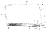
説明の便宜上、まず、車両用ウインドウシェード装置の全体動作について説明する。図1〜図3は車両用ウインドウシェード装置20が車両のウインドウ10近傍部分に取付けられた状態を示す説明図であり、図1はウインドウシェード30が完全に巻取られた状態、図2はウインドウシェード30が途中まで引出された状態、図3はウインドウシェード30が完全に引出された状態を示している。本実施形態では、ウインドウ10が後部座席側方のサイドウインドウ、即ち、BピラーとCピラーとの間にあるサイドウインドウである場合を想定して説明するが、その他、荷室側方のウインドウ等であってもよい。
For convenience of explanation, the overall operation of the vehicle window shade device will be described first. 1 to 3 are explanatory views showing a state in which the vehicle
ウインドウ10は、第1の枠部であるドアパネル12の上側の縁部12aと、この縁部12aに対して傾斜する(ここでは鈍角で傾斜する)第2の枠部である一方の側枠部14aとの内側に配設される。
The
より具体的には、ウインドウ10は、ドアパネル12の上方にあるウインドウ枠14内に開閉可能に配設される。すなわち、ドアパネル12の上側の縁部12aの上方に、その上方領域の両側及び上側の三方を囲うウインドウ枠14が配設されている。ウインドウ枠14の一方(図1〜図3の左側、車両において後ろ側)の側枠部14aは、ドアパネル12の上側の縁部12aの後端部から鈍角となる斜め姿勢、ここでは、車両後方側に傾斜する姿勢で上方に延出している。また、ウインドウ枠14の他方(図1〜図3の右側、車両において前側)の側枠部14bは、ドアパネル12の上側の縁部12aの前端部から鋭角となる斜め姿勢、ここでは、車両後方側に傾斜する姿勢で上方に延出している。つまり、一方の側枠部14aと他方の側枠部14bとは並行姿勢である。もっとも、両側枠部14a、14bが並行姿勢であることは必須ではない。ウインドウ枠14の上側枠部14cは、ドアパネル12の上側の縁部12aに対して斜め(やや斜め)姿勢で上側の縁部12aに対して間隔をあけて配設されている。もっとも、ウインドウ枠14の上側枠部14cは、縁部12aに対して平行姿勢であってもよい。
More specifically, the
ウインドウ10は、ドアパネル12内から上記ウインドウ枠14内に開閉可能に設けられる。ウインドウ10がウインドウ枠14内全体を塞ぐように閉じられた状態で、ウインドウ10の露出領域は、ドアパネル12の縁部12a及びウインドウ枠14によって囲まれる内部領域である。
The
通常、後部座席に乗員が着座した姿勢で、乗員の顔は、一方の側枠部14aの内側に位置するため、当該一方の側枠部14a近傍で、乗員の顔を外部から遮蔽できるようにすることが好ましい。この車両用ウインドウシェード装置20は、一方の側枠部14aの近傍で、ウインドウシェード30と一方の側枠部14aとの隙間をなるべく小さくする技術に関する。
Usually, with the occupant seated in the rear seat, the occupant's face is positioned inside the one
すなわち、本実施形態では、ウインドウシェード30を巻取る巻取シャフト40が、ドアパネル12の縁部12aに沿って配設されている。そして、ウインドウシェード30の引出度合に応じて、巻取シャフト40が、その軸方向、即ち、ドアパネル12の上側の縁部12aに沿って移動するようになっている。すなわち、ウインドウシェード30が巻取シャフト40に完全に巻取られた状態では、巻取シャフト40は、一方の側枠部14aから離れた位置に存在している。この状態では、巻取シャフト40と一方の側枠部14aとの間に隙間が生じており、ウインドウシェード30は、前記隙間にも延出した状態で巻取シャフト40に巻取られている(図1参照)。
That is, in this embodiment, the winding
この状態からウインドウシェード30が引出され、ウインドウシェード30がウインドウ10の上下方向の途中までを閉塞すると、巻取シャフト40はその軸方向に沿って一方の側枠部14a側に移動する。この移動にあわせて、ウインドウシェード30のうち一方の側枠部14aに沿った縁部が当該一方の側枠部14a側に移動する。この移動によって、ウインドウシェード30のうち一方の側枠部14a側の側縁部と一方の側枠部14aとの隙間を狭めることができる(図2参照)。
When the
上記状態からウインドウシェード30がさらに引出され、ウインドウシェード30がウインドウ10のほぼ全体を遮蔽すると、巻取シャフト40はその軸方向に沿ってさらに一方の側枠部14a側に移動する。この移動にあわせて、続けて、ウインドウシェード30のうち一方の側枠部14aに沿った縁部が当該一方の側枠部14a側にさらに移動する。この移動により、ウインドウシェード30のうち一方の側枠部14a側の側縁部と一方の側枠部14aとの隙間を狭めることができる(図3参照)。
When the
このため、ウインドウシェード30の引出途中及びウインドウシェード30を完全に引出した状態のいずれにおいても、ウインドウシェード30のうち一方の側枠部14a側の側縁部と一方の側枠部14aとの隙間をなるべく小さくすることができる。
For this reason, the gap between the side edge part on the one
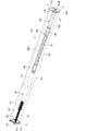
上記を実現するため、本実施形態に係る車両用ウインドウシェード装置20において、ウインドウシェード30の引出状態に応じて巻取シャフト40を移動させるための構成について説明する。図4は車両用ウインドウシェード装置20を示す透過斜視図であり、図5は車両用ウインドウシェード装置20の一端側部分の分解斜視図であり、図6は車両用ウインドウシェード装置20の他端側部分の分解斜視図である。なお、以下の各図においてウインドウシェード30は省略されている。
In order to realize the above, a configuration for moving the winding
この車両用ウインドウシェード装置20は、ウインドウシェード30と、巻取シャフト40と、一対の支持シャフトとしてのネジ支持シャフト50及び付勢側支持シャフト60と、補強シャフト70と、付勢機構80とを備えている。
The vehicle
ウインドウシェード30は、メッシュ状の布、樹脂シート等の材料を裁断、縫製等して形成されたシート状の部材である(図3参照)。ここでは、ウインドウシェード30は、上記ウインドウ10のうちドアパネル12の縁部12a及びウインドウ枠14によって囲まれる露出部分を覆う大きさ及び形状に形成されている。ウインドウシェード30は、ウインドウ10の略全体を遮蔽できる大きさ及び形状であることが好ましいが、ウインドウ10の一部を遮蔽する形状及び大きさ、或は、複数のウインドウを一括して遮蔽可能な形状及び大きさに形成されていてもよい。ウインドウシェード22の引出長は、例えば、400mm〜500mmである。
The
このウインドウシェード30の引出方向側端部にステイ32が取付けられている。ここでは、ウインドウシェード30は、巻取シャフト40によって巻取られ、当該巻取シャフト40からウインドウ10に沿って上方に引出されるため、ウインドウシェード30の上側端部が引出方向側端部である。このステイ32は、ウインドウシェード30の巻取状態では、後述するケース46の引出用スリット46h内或はその開口部に配設されている。この状態からステイ32をウインドウ10に沿って引張ることで、ウインドウシェード30が引出用スリット46hを通じてウインドウ10に沿って引出される。また、ステイ32には、ウインドウ枠14の上側枠部14cに設けられた被係止部に係止可能なフック部(図示省略)が設けられている。そして、ウインドウシェード30を引出した状態で、当該フック部を当該被係止部に係止することで、ウインドウシェード30が引出された状態に維持される。
A
巻取シャフト40は、ウインドウシェード30を巻取可能に構成されている。より具体的には、巻取シャフト40は、シャフト本体部41と、ネジ支持軸受42と、軸受43とを備えている。巻取シャフト40の長さ寸法は、ドアパネル12の縁部12aの長さ寸法及び後述するケース46の長さ寸法よりも小さい。従って、巻取シャフト40を、当該縁部12a及びケース46の長手方向に沿った姿勢で配設した状態で、当該縁部12a及びケース46の長手方向に沿って移動できるようになっている。
The winding
シャフト本体部41は、金属等で形成された筒部材に形成されている。このシャフト本体部41の内周部には、その長手方向に沿って延びる突条部が形成されている。
The shaft
ネジ支持軸受42は、シャフト本体部41の一端部内に挿入可能な筒状に形成されている(図5参照)。ネジ支持軸受42の外周部には、その軸方向に沿ってスプライン溝42aが形成されている。本ネジ支持軸受42を上記シャフト本体部41の一端部内に挿入した状態で、シャフト本体部41の内周部の突条部がスプライン溝42aに嵌り込み、ネジ支持軸受42がシャフト本体部41に対して回転止されるようになっている。また、ネジ支持軸受42の一端部には鍔部42bが形成されている。ネジ支持軸受42がシャフト本体部41の一端部内に挿入された状態で、鍔部42bがシャフト本体部41の一端側開口部に当接することにより、ネジ支持軸受42の軸方向の位置決めが図られている。また、ネジ支持軸受42の内周部には、後述するネジ支持シャフト50のネジ部51を螺合可能なネジ溝が形成されたネジ孔42sが形成されている。
The screw support bearing 42 is formed in a cylindrical shape that can be inserted into one end of the shaft body 41 (see FIG. 5). A
軸受43は、シャフト本体部41の他端部内に挿入可能な筒状に形成されている(図6参照)。軸受43の外周部には、その軸方向に沿ってスプライン溝43aが形成されている。本軸受43を上記シャフト本体部41の他端部内に挿入した状態で、シャフト本体部41の内周部の突条部がスプライン溝43aに嵌り込み、軸受43がシャフト本体部41に対して回転止されるようになっている。また、軸受43の一端部には鍔部43bが形成されている。軸受43がシャフト本体部41の他端部内に挿入された状態で、鍔部43bがシャフト本体部41の他端側開口部に当接することで、軸受43の軸方向の位置決めが図られている。また、軸受43の内周部には、後述する付勢側支持シャフト60を回転可能に挿通可能な挿通孔43hが形成されている。
The
この巻取シャフト40は、ケース46内に収容される。ケース46は、アルミニウム等の金属で形成された長尺部材であり、巻取シャフト40及び当該巻取シャフト40に巻取られたウインドウシェード30を収容可能な筒状部47と、一対のフランジ部48とを備えている(図5及び図6参照)。筒状部47の一側部にはスリットが形成されており、このスリットを挟む両側縁部から外方に延出するようにして一対のフランジ部48が形成されている。筒状部47に形成された前記スリット及び前記一対のフランジ部48に挟まれる空間によって引出用スリット46hが形成されている。ウインドウシェード30は、本引出用スリット46hを通じて引出及び巻取りされ、ウインドウシェード30が完全に巻取られた状態で、ステイ32が引出用スリット46hの開口部或はその内部に配設される。
The take-up
なお、ケース46には、ネジSを螺合可能なネジ止部45が形成されている(図6参照)。ここでは、ケース46の横断面形状を同じにすることによって当該ケース46を容易に加工するため、ねじ止部45は、ケース46の一部を、その長手方向に沿って延びる細筒状に突出させた形状とされているが、これは必須ではない。そして、後述するネジ支持シャフト50のシャフト支持部54及び付勢側支持シャフト50のシャフト支持部54Bが、本ネジ止部45を利用してネジ止固定される。つまり、ケース46は、シャフト支持部54、54Bを、巻取シャフト40の両端側で回転規制した状態で固定する役割を有している。
The
車両用ウインドウシェード装置20の一端側部分、即ち、ネジ支持シャフト50側の部分について説明する。図7は車両用ウインドウシェード装置20の一端側部分を示す縦断面図であり、図9及び図10はキャップ受部56及びキャップ部材74を示す分解斜視図である。
The one end side portion of the vehicle
図4、図5、図7、図9及び図10に示すように、ネジ支持シャフト50は、巻取シャフト40の一端部を回転可能に支持するように構成されている。
As shown in FIGS. 4, 5, 7, 9, and 10, the
より具体的には、ネジ支持シャフト50は、樹脂により形成された棒状部材に形成されている。樹脂としては、ナイロン樹脂等を用いることができる。ネジ支持シャフト50の外周の長手方向全体にネジ溝が形成され、ネジ支持シャフト50の長手方向全体がネジ部51とされている。もっとも、ネジ支持シャフト50のうちの一部がネジ部とされていてもよい。ネジ部51の長さ寸法は、巻取シャフト40を移動させたい長さ寸法(例えば、40mm)等によって決定される。また、ネジ支持シャフト50の中心軸に沿って中心穴52が形成されている。ここでは、中心穴52は、ネジ支持シャフト50の一端部(巻取シャフト40の支持状態で外側を向く端部)で開口しその他端部で閉塞されている。即ち、中心穴52は、非貫通孔である。もっとも、中心穴52は、ネジ支持シャフト50を貫通する孔であってもよい。もっとも、本車両用ウインドウシェード装置20の実際の動作状況において、ネジ部51のうちネジ孔42sと螺合する部分に、中心穴52が形成されていることが好ましい。この部分において、その厚みを小さくして、そのネジ部51の部分の精度を高めることが好ましいからである。ネジ支持シャフト50の直径は、巻取シャフト40の一巻によってウインドウシェード22を巻取りたい長さ寸法等によって設定される。中心穴52の直径は、樹脂を加工する際の精度上、ネジ支持シャフト50に対して好ましいとされる厚み等に応じて設定される。ネジ支持シャフト50の直径の一例は8mmであり、この場合の中空孔52の直径は例えば、3mmである。この場合、ネジ支持シャフト50の厚みを2.5mm程度にすることができ、溝の深さが1mm程度のネジ部51を精度よく形成できる。なお、中心穴52は、円孔である必要はなく、角穴等であってもよい。
More specifically, the
このネジ支持シャフト50は、シャフト支持部54と共に樹脂によって金型一体形成されている。シャフト支持部54は、上記ケース46の一端部にネジ止め等により固定可能な部材である。ネジ支持シャフト50は、本シャフト支持部54に対して突出姿勢で一体形成されることにより、巻取シャフト40を回転可能に支持する。
The
ここでは、シャフト支持部54は、ケース46の一端側開口を閉塞可能な板状部材に形成されている。より具体的には、シャフト支持部54は、円板部54aの外周部に突出板部54bが突出する板形状に形成されている(図9及び図10参照)。円板部54aは、筒状部47の一端部を閉塞可能な板状部分に形成され、突出板部54bは一対のフランジ部48の一端側開口を閉塞可能な板状部分に形成されている。ネジ支持シャフト50は、円板部54aの中央部に当該円板部54aに対して直交する姿勢で突設されている。また、シャフト支持部54の外周部にネジ挿通孔を有するネジ止片54cが突設されている。そして、ケース46の一端側開口を閉塞するように本シャフト支持部54を配設した状態で、ネジSをネジ止片54cに挿通してケース46のネジ止部45に螺合させることで、本シャフト支持部54がケース46の一端部に取付固定される。この状態で、シャフト支持部54に突設されたネジ支持シャフト50が、筒状部47の中心軸に沿って配設される。このネジ支持シャフト50が巻取シャフト40のネジ支持軸受42のネジ孔42s内に螺合されることで、巻取シャフト40の一端部が筒状部47内で回転可能かつその回転に伴ってその軸方向に移動可能に支持される。
Here, the
なお、上記シャフト支持部54に対してネジ支持シャフト50を形成するためには、例えば、図8に示すように、金型102にネジ溝が形成された孔状の金型面104を形成し、この金型面104にて上記ネジ支持シャフト50の外形状を形成するとよい。ネジ支持シャフト50の外周面に対する金型102の離型は、ネジの螺旋方向Aに沿って金型102をネジ支持シャフト50に対して相対回転させることによって行うことができる。
In order to form the
図4、図5、図7に示すように、補強シャフト70は、上記中心穴52に挿通可能に構成されている。すなわち、補強シャフト70は、中心穴52内に隙間無く挿通できる棒状部材に形成されている。補強シャフト70の長さ寸法は中心穴52の長さと同じであることが好ましいが、これは必須ではない。例えば、補強シャフト70は、中心穴52の途中に至る程度の長さ寸法であってもよい。中心穴が貫通孔である場合には、補強シャフトは中心穴より長く、ネジ支持シャフトの先端部に突出していてもよい。また、補強シャフト70は、鉄、鋼鉄等の金属で形成されていることが好ましいが、これも必須ではなく、樹脂等で形成されていてもよい。ここでは、補強シャフト70は、金属で形成されている例で説明する。
As shown in FIGS. 4, 5, and 7, the reinforcing
また、補強シャフト70の一端部には頭部72が形成されている。ここでは、頭部72は、補強シャフト70の一端部の外周全体に亘って突出する円板状部分に形成されている。そして、補強シャフト70がシャフト支持部54を通ってネジ支持シャフト50の中心穴52内に挿通されると、前記頭部72がシャフト支持部54に対してその外側より当接するようになっている。これにより、補強シャフト70がシャフト支持部54に対してより確実に直交姿勢に維持される。また、本補強シャフト70が挿通されたネジ支持シャフト50についても、補強シャフト70の支持構造によってシャフト支持部54に対してより確実に直交姿勢に維持される。
A
なお、上記頭部72は、中心穴52への挿通方向における補強シャフト70の位置決めを図る役割をも有している。
The
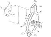
また、図4、図5、図7、図9及び図10に示すように、上記シャフト支持部54の外面にはキャップ受部56が設けられ、このキャップ受部56にキャップ部材74が取付けられるようになっている。そして、このキャップ部材74によって、頭部72が中心穴52に向けて押え込まれ、これにより、補強シャフト70の抜け止が図られる。なお、頭部72があることは必須ではない。頭部72が無い場合でも、キャップ受部74及びキャップ部材74と同様構成によって、補強シャフト70の外向き端部を中心穴52に向けて押え込んで、補強シャフト70の抜止めを図ることができる。
As shown in FIGS. 4, 5, 7, 9, and 10, a
より具体的には、シャフト支持部54の外面に、当該外面に開口する中心穴52の開口を囲うようにして半円状の受壁部56aが形成されている(図9参照)。上記頭部72は、当該受壁部56a内でシャフト支持部54の外面に当接される。また、受壁部56aの内周部のうちシャフト支持部54の外面から離れた部分に、その内周側に向けて突出する突出部56bが形成されている。この突出部56bは、受壁部56aの両端部で外方(図9では上方)に向けて突出している。
More specifically, a semicircular
キャップ部材74は、樹脂等で形成された部材であり、キャップ本体部74aと、突部74cとを有している(図9及び図10参照)。キャップ本体部74aは、上記受壁部56a内に配設可能に形成されると共に、上記頭部72を収容可能な凹部74bを有している。突部74cは、キャップ本体部74aの一主面に突設され、上記突出部56b内に配設可能に構成されている。
The
そして、中心穴52内に補強シャフト70を差込み、頭部72をシャフト支持部54の外面に接触させるように配設した状態で、キャップ部材74をキャップ受部56内に差込む。より具体的には、キャップ部材74を、キャップ受部56に対して補強シャフト70の軸方向に対して直交する方向(図9及び図10の矢符B参照)に差込み、キャップ本体部74aを受壁部56a内に配設し、突部74cを突出部56b内に配設する。これにより、頭部72が凹部74b内に収容された状態で、キャップ本体部74aにより抜け方向への位置決めが図られる。
Then, the
なお、上記キャップ受部56及びキャップ部材74を採用することは必須ではない。例えば、補強シャフト70が中心穴52内に接着剤、ネジ止め等で固定されていてもよい。また、ネジ支持シャフト50を金型形成する際、補強シャフト70がインサート物としてインサートされていてもよい。
It is not essential to employ the
車両用ウインドウシェード装置20の他端側部分、即ち、付勢側支持シャフト60側の部分について説明する。図11は車両用ウインドウシェード装置20の他端側部分を示す縦断面図である。
The other end portion of the vehicle
図4、図5、図6及び図11に示すように、付勢側支持シャフト60は、巻取シャフト40の他端部を回転可能に支持するように構成されている。
As shown in FIGS. 4, 5, 6, and 11, the urging-
より具体的には、付勢側支持シャフト60は、樹脂により形成された棒状部材に形成されている。この付勢側支持シャフト60の外周部には、上記ネジ支持シャフト50とは異なりネジ溝が形成されていない。また、付勢側支持シャフト60の中心軸に沿って中心穴62が形成されている。ここでは、中心穴62は、付勢側支持シャフト60の一端部(巻取シャフト40の支持状態で外側を向く端部)で開口しその他端部で閉塞されている。即ち、中心穴62は、非貫通孔である。もっとも、中心穴52は、付勢側支持シャフト60を貫通する孔であってもよい。また、本付勢側支持シャフト60には中心穴62が形成されていなくてもよい。
More specifically, the urging
この付勢側支持シャフト60は、シャフト支持部54Bと共に樹脂によって金型一体形成されている。樹脂としては、ネジ支持シャフト50と同様にナイロン樹脂等を用いることができる。シャフト支持部54Bは、上記シャフト支持部54と面対称構造を有する部材である。付勢側支持シャフト60は、本シャフト支持部54Bに対して突出姿勢で一体形成されている。そして、上記シャフト支持部54と同様に、シャフト支持部54Bがケース46の他端側開口を閉塞するように、ケース46の他端部にネジSによって取付固定される。この状態で、シャフト支持部54Bに突設された付勢側支持シャフト60が、筒状部47の中心軸に沿って配設される。この付勢側支持シャフト60が巻取シャフト40の軸受43の挿通孔43h内に嵌め込まれることで、巻取シャフト40の他端部が筒状部47内で回転可能かつその軸方向に移動可能に支持される。また、この状態で、付勢側支持シャフト60は、巻取シャフト40の一端部内に挿通されている。
The urging
また、この付勢側支持シャフト60の中心穴62内にも、ネジ支持シャフト50と同様に、補強シャフト70Bが挿通され、当該付勢側支持シャフト60の強度向上が図られている。補強シャフト70Bは、上記補強シャフト70と同様に鉄、鋼鉄等の金属により製造されるとよい。また、シャフト支持部54Bの外面に、キャップ受部56Bが設けられ、このキャップ受部56にキャップ部材74Bが取付けられる。これにより、補強シャフト70Bの抜け止が図られている。
Further, similarly to the
上記シャフト支持部54B、補強シャフト70B、キャップ受部56B及びキャップ部材74Bは、それぞれシャフト支持部54、補強シャフト70、キャップ受部56及びキャップ部材74と面対称構造を有する部材であるため、ここでは、それらの詳細な説明を省略する。
The
また、図4、図6及び図11に示すように、巻取シャフト40のうち、本付勢側支持シャフト60により支持される側の端部に、当該巻取シャフト40を、ウインドウシェード30を巻取る方向に付勢する付勢機構80が設けられている。
As shown in FIGS. 4, 6, and 11, the winding
付勢機構80は、付勢部材としてのコイルバネ82と、コイルバネ82を覆う弾性チューブ86とを備えている。
The urging
巻取シャフト40のシャフト本体部41内で、コイルバネ82の一端部が付勢側支持シャフト60の一端部に連結されている。ここでは、コイルバネ82の一端部のL字状部分の先端部(図6参照)が、付勢側支持シャフト60の先端部に形成された孔に挿通されることで(図11参照)、コイルバネ82の一端部が付勢側支持シャフト60の先端部に相対回転不能に連結されている。
One end portion of the
また、コイルバネ82の他端部は巻取シャフト40の内部に相対回転不能に連結されている。ここでは、バネ連結部材88を用いて前記連結が行われている。バネ連結部材88は、シャフト本体部41内に挿通可能な長尺部材に形成されている。バネ連結部材88の外周部の少なくとも一部には、その軸方向に沿ってスプライン溝88aが形成されている。そして、本バネ連結部材88がシャフト本体部41内に配設された状態で、シャフト本体部41の内周部の突条部がスプライン溝88aに嵌り込む。これにより、バネ連結部材88が、シャフト本体部41内でその軸方向に沿って移動可能な状態で、回転止されるようになっている。また、バネ連結部材88の一端部には、その径方向に沿って延びる孔が形成されており、コイルバネ82の他端部のL字状部分の先端部(図6参照)が当該孔に挿通されることで(図11参照)、コイルバネ82の他端部がバネ連結部材88に対して相対回転不能に連結されている。
The other end of the
そして、コイルバネ82の各端部を付勢側支持シャフト60及びバネ連結部材88に連結した状態で、バネ連結部材88、コイルバネ82及び付勢側支持シャフト60の先端部をシャフト本体部41内に挿入配置する。この状態で、付勢側支持シャフト60に対して巻取シャフト40が回転すると、巻取シャフト40と共にバネ連結部材88も回転する。これにより、付勢側支持シャフト60とバネ連結部材88との間でコイルバネ82が捻られる。このコイルバネ82の捻れを元に戻そうとする力によって、付勢側支持シャフト60に対してバネ連結部材88及び巻取シャフト40が上記とは逆方向に付勢される。この付勢力がウインドウシェード30を巻取る力として作用する。
Then, with the end portions of the
また、弾性チューブ86は、ゴム等のエラストマーによって形成された部材であり、上記コイルバネ82を覆う筒状部材に形成されている。弾性チューブ86は、コイルバネ82の自然長よりも大きい長さ寸法に形成されている。
The
また、付勢側支持シャフト60のうちコイルバネ82が連結される部分よりも中間よりの位置に環状溝62gが形成され(図11参照)、この環状溝62gにゴム等のエラストマーによって形成された弾性リング89が位置決め固定されている。また、バネ連結部材88には、スプライン溝88aが形成された部分とコイルバネ82が連結された部分との間に、コイルバネ82側に向く段部88sが形成されている。弾性チューブ86がコイルバネ82に外嵌めされた状態で、弾性チューブ86の両端部はバネ連結部材88の一端部及び付勢側支持シャフト60のうちコイルバネ82が連結された側の端部にも外嵌めされ、上記段部88sと弾性リング89との間に配設されている。この弾性チューブ86は、上記段部88sと弾性リング89とによってそれらの間に位置するように規制されている。
Further, an
以上のように構成された車両用ウインドウシェード装置20の動作について説明する。
The operation of the vehicle
まず、初期状態では、ウインドウシェード30は巻取シャフト40に完全に巻取られており、ウインドウ10の全体が露出している(図1及び図4参照)。この状態では、巻取シャフト40は、一方の側枠部14aより離れた位置に存在している。ここでは、巻取シャフト40の他端部がケース46の他端部に達しシャフト支持部54B近くに位置している。
First, in the initial state, the
上記初期状態からウインドウシェード30がウインドウ10に沿って引出されると、この引出しに伴って巻取シャフト40が回転する。すると、巻取シャフト40の一端部のネジ支持軸受42のネジ孔42sと、ネジ支持シャフト50との螺合によって、巻取シャフト40が一方の側枠部14a側に移動する(図2及び図12参照)。そして、巻取シャフト40がケース46の中間部に位置し、ウインドウシェード30はウインドウ10の上下方向中間部まで引出された状態となる。
When the
ウインドウシェード30がウインドウ10に沿ってさらに引出されると、この引出しに伴って巻取シャフト40がさらに回転する。巻取シャフト40の一端部のネジ支持軸受42のネジ孔42sと、ネジ支持シャフト50との螺合によって、巻取シャフト40がさらに一方の側枠部14a側に移動する(図3及び図13参照)。そして、巻取シャフト40がケース46の一端部に達し、シャフト支持部54近くに位置するようになる。この状態で、ウインドウシェード30は、ウインドウ10のほぼ全体を覆うように引出され、その引出方向先端側のステイ32が上側枠部14cに取付けられることで、ウインドウシェード30が引出された状態に維持される。
When the
上記のようにウインドウシェード30が引出される際、また、巻取シャフト40は、付勢側支持シャフト60に対して相対回転されるため、巻取シャフト40側に相対回転不能に取付けられたバネ連結部材88と付勢側支持シャフト60との間でコイルバネ82が捻られる。従って、上記ウインドウシェード30を引出す力を解除すると、コイルバネ82の捻れを解消しようとする力によって、巻取シャフト40が、ウインドウシェード30を巻取る方向に回転され、ウインドウシェード30が巻取シャフト40に巻取られる。この際、巻取シャフト40の一端部のネジ支持軸受42のネジ孔42sとの螺合によって、巻取シャフト40は上記とは逆方向に移動して、上記初期状態の位置に戻る。
When the
また、巻取シャフト40の移動に伴って、付勢側支持シャフト60を軸として、巻取シャフト40側の軸受43が移動し、バネ連結部材88はシャフト本体部41内を移動する。この際、弾性チューブ86は、段部88sと弾性リング89との間に位置するように規制されているため、コイルバネ82を覆った状態がより確実に維持される。
Further, along with the movement of the winding
以上のように構成された車両用ウインドウシェード装置20によると、巻取シャフト40の一端部に形成されたネジ孔42sとネジ支持シャフト50のネジ部51との螺合によって、ウインドウシェード30の引出度合、即ち、巻取シャフト40の回転度合に応じて巻取シャフト40をその軸方向に沿って移動させることができる。これにより、巻取シャフト40が第1の枠部である縁部12aに沿って配設されている場合において、この縁部12aに対して傾斜する第2の枠部である一方の側枠部14aとウインドウシェード30のうちの一方の側枠部14a側の側縁部との隙間をなるべく小さくするようにすることができる。
According to the vehicle
また、ネジ支持シャフト50が樹脂によって形成されているため、その軽量化等を図ることができる。この際、ネジ支持シャフト50に中心穴52が形成されているため、ネジ支持シャフト50の厚みをなるべく小さくして樹脂ヒケ等を抑制し、ネジ支持シャフト50に形成されるネジ部51の精度向上を図ることができる。また、中心穴52に補強シャフト70が挿通されるため、ネジ部51の強度向上を図ることができる。
Further, since the
また、補強シャフト70が金属製であるため、よりネジ部51の強度向上を図ることができる。
Further, since the reinforcing
しかも、補強シャフト70の頭部72がシャフト支持部54に対して外側から当接した状態で、補強シャフト70がシャフト支持部54を通って中心穴52に挿通されているため、ネジ支持シャフト50をシャフト支持部54に対してより確実に直交姿勢で支持することができ、ネジ支持シャフト50による巻取シャフト40の支持強度がより向上する。
Moreover, since the
また、シャフト支持部54の外面にキャップ受部56が設けられ、このキャップ受部56に取付けられたキャップ部材74が頭部72を中心穴52に向けて押え込んでいるため、簡易に補強シャフト70の抜止を図ることができる。
Further, the
しかも、キャップ部材74は、キャップ受部56に対して補強シャフト70の軸方向に対して直交する方向に差込まれるため、補強シャフト70をより簡易かつ確実に抜止めすることができる。
Moreover, since the
なお、補強シャフト70B、キャップ受部56B、キャップ受部56Bは、付勢側支持シャフト60側に設けられているため、この付勢側支持シャフト60側についても上記と同様の効果を得ることができる。
In addition, since the reinforcing shaft 70B, the
また、コイルバネ82を弾性チューブ86によって覆っているため、コイルバネ82とシャフト本体部41の内周部との接触音が抑制される。また、本実施形態のように、シャフト本体部41に対して付勢側支持シャフト60及びコイルバネ82が移動する構成では、コイルバネ82を覆う弾性チューブ86が位置ずれする恐れがある。そこで、本実施形態のように、付勢側支持シャフト60に弾性リング89を位置決め固定することで、弾性チューブ86の付勢側支持シャフト60側への位置ずれを抑制することができる。これにより、弾性チューブ86がコイルバネ82を覆う状態がより確実に維持され、コイルバネ82による接触音がより確実に維持される。なお、弾性リング89自体は、バネ等のエラストマーによって形成されているため、シャフト本体部41の内周部との間で接触音を発生させ難い。また、シャフト本体部41内側への弾性チューブ86の位置ずれは、バネ連結部材88の段部88sによって抑制されている。
Further, since the
なお、上記実施形態において、巻取シャフト40の両側に、ネジ支持シャフト50が設けられていてもよい。
In the above embodiment, screw
また、付勢機構80は、ネジ支持シャフト50側に組込まれていてもよい。また、ネジ支持シャフト50側だけに組込まれていてもよい。
Further, the urging
以上のようにこの発明は詳細に説明されたが、上記した説明は、すべての局面において、例示であって、この発明がそれに限定されるものではない。例示されていない無数の変形例が、この発明の範囲から外れることなく想定され得るものと解される。 As described above, the present invention has been described in detail. However, the above description is illustrative in all aspects, and the present invention is not limited thereto. It is understood that countless variations that are not illustrated can be envisaged without departing from the scope of the present invention.
10 ウインドウ
12 ドアパネル
12a 縁部
14 ウインドウ枠
14a、14b 側枠部
20 車両用ウインドウシェード装置
30 ウインドウシェード
40 巻取シャフト
41 シャフト本体部
42 ネジ支持軸受
42s ネジ孔
43 軸受
43h 挿通孔
46 ケース
50 ネジ支持シャフト
51 ネジ部
52 中心穴
54、54B シャフト支持部
56、56B キャップ受部
60 付勢側支持シャフト
62 中心穴
62g 環状溝
70、70B 補強シャフト
72 頭部
74、74B キャップ部材
80 付勢機構
82 コイルバネ
86 弾性チューブ
88 バネ連結部材
89 弾性リング
DESCRIPTION OF
Claims (5)
前記ウインドウを遮蔽可能なウインドウシェードと、
前記ウインドウシェードを巻取可能な巻取シャフトと、
前記巻取シャフトの両端を回転可能に支持する一対の支持シャフトと、
前記巻取シャフトの少なくとも一端側に設けられ、前記巻取シャフトを、前記ウインドウシェードを巻取る方向に付勢する付勢機構と、
を備え、
前記巻取シャフトの少なくとも一端部の内周面にネジ孔が形成され、
前記一対の支持シャフトの少なくとも一方が、樹脂により形成されると共に、前記ネジ孔に螺合するネジ部とそのネジ部の中心軸に沿った中心穴とを有するネジ支持シャフトとされ、
前記中心穴に補強シャフトが配設された、車両用ウインドウシェード装置。 A vehicle window shade device for covering and releasably covering a window,
A window shade capable of shielding the window;
A winding shaft capable of winding the window shade;
A pair of support shafts rotatably supporting both ends of the winding shaft;
An urging mechanism that is provided on at least one end side of the winding shaft and urges the winding shaft in a direction in which the window shade is wound;
With
A screw hole is formed on the inner peripheral surface of at least one end of the winding shaft,
At least one of the pair of support shafts is made of resin, and is a screw support shaft having a screw portion screwed into the screw hole and a center hole along the center axis of the screw portion,
A vehicle window shade device in which a reinforcing shaft is disposed in the center hole.
前記補強シャフトは、金属製である、車両用ウインドウシェード装置。 The vehicle window shade device according to claim 1,
The vehicle window shade device, wherein the reinforcing shaft is made of metal.
前記ネジ支持シャフトは、前記補強シャフトをインサート物とする金型成形品である、車両用ウインドウシェード装置。 The vehicle window shade device according to claim 1 or 2,
The window support device for a vehicle , wherein the screw support shaft is a molded product using the reinforcing shaft as an insert .
前記ネジ支持シャフトが、前記巻取シャフトを回転可能に支持する突出姿勢でシャフト支持部に対して一体形成され、
前記補強シャフトが前記シャフト支持部を通じて前記ネジ支持シャフトの前記中心穴に挿通されると共に、前記補強シャフトに前記シャフト支持部に対して外側から当接する頭部が形成されている、車両用ウインドウシェード装置。 The vehicle window shade device according to claim 1 or 2,
The screw support shaft is integrally formed with the shaft support portion in a projecting posture to rotatably support the winding shaft;
The vehicle window shade, wherein the reinforcing shaft is inserted through the shaft support portion into the center hole of the screw support shaft, and a head portion is formed on the reinforcement shaft so as to come into contact with the shaft support portion from the outside. apparatus.
前記ネジ支持シャフトが、前記巻取シャフトを回転可能に支持する突出姿勢でシャフト支持部に対して一体形成され、
前記補強シャフトが前記シャフト支持部を通じて前記ネジ支持シャフトの前記中心穴に挿通され、
前記シャフト支持部の外面にキャップ受部が設けられ、
前記キャップ受部に取付けられた状態で、前記補強シャフトを前記中心穴に向けて押え込むキャップ部材をさらに備える車両用ウインドウシェード装置。 A vehicle window shade device according to any one of claims 1, 2, and 4,
The screw support shaft is integrally formed with the shaft support portion in a projecting posture to rotatably support the winding shaft;
The reinforcing shaft is inserted through the shaft support portion into the center hole of the screw support shaft;
A cap receiving part is provided on the outer surface of the shaft support part,
A vehicle window shade device further comprising a cap member that presses the reinforcing shaft toward the center hole in a state of being attached to the cap receiving portion.
Priority Applications (2)
| Application Number | Priority Date | Filing Date | Title |
|---|---|---|---|
| JP2011183725A JP5936834B2 (en) | 2011-08-25 | 2011-08-25 | Window shade device for vehicle |
| PCT/JP2012/069082 WO2013027533A1 (en) | 2011-08-25 | 2012-07-27 | Window shade device for vehicle |
Applications Claiming Priority (1)
| Application Number | Priority Date | Filing Date | Title |
|---|---|---|---|
| JP2011183725A JP5936834B2 (en) | 2011-08-25 | 2011-08-25 | Window shade device for vehicle |
Publications (3)
| Publication Number | Publication Date |
|---|---|
| JP2013043593A JP2013043593A (en) | 2013-03-04 |
| JP2013043593A5 JP2013043593A5 (en) | 2014-10-09 |
| JP5936834B2 true JP5936834B2 (en) | 2016-06-22 |
Family
ID=47746284
Family Applications (1)
| Application Number | Title | Priority Date | Filing Date |
|---|---|---|---|
| JP2011183725A Active JP5936834B2 (en) | 2011-08-25 | 2011-08-25 | Window shade device for vehicle |
Country Status (2)
| Country | Link |
|---|---|
| JP (1) | JP5936834B2 (en) |
| WO (1) | WO2013027533A1 (en) |
Families Citing this family (2)
| Publication number | Priority date | Publication date | Assignee | Title |
|---|---|---|---|---|
| US10501988B2 (en) * | 2017-02-02 | 2019-12-10 | Hunter Douglas Inc. | Power assist module for coverings for architectural structures |
| KR102253655B1 (en) * | 2019-10-21 | 2021-05-18 | 코리아에프티 주식회사 | Shading apparatus for car windows |
Family Cites Families (5)
| Publication number | Priority date | Publication date | Assignee | Title |
|---|---|---|---|---|
| JP3092031U (en) * | 2002-08-09 | 2003-02-28 | 秀枝 陶 | Roll screen rail device |
| JP4355741B2 (en) * | 2007-10-24 | 2009-11-04 | 株式会社鹿田産業 | Roll screen device |
| JP5405214B2 (en) * | 2009-07-03 | 2014-02-05 | アスモ株式会社 | Shading device |
| JP5366732B2 (en) * | 2009-09-18 | 2013-12-11 | アスモ株式会社 | Shading device |
| JP5410311B2 (en) * | 2010-01-20 | 2014-02-05 | 芦森工業株式会社 | Sunshade equipment |
-
2011
- 2011-08-25 JP JP2011183725A patent/JP5936834B2/en active Active
-
2012
- 2012-07-27 WO PCT/JP2012/069082 patent/WO2013027533A1/en active Application Filing
Also Published As
| Publication number | Publication date |
|---|---|
| JP2013043593A (en) | 2013-03-04 |
| WO2013027533A1 (en) | 2013-02-28 |
Similar Documents
| Publication | Publication Date | Title |
|---|---|---|
| US8113672B2 (en) | Outer mirror | |
| JP5646934B2 (en) | Sunshade equipment | |
| JP6211375B2 (en) | Power supply device | |
| JP5602033B2 (en) | Tonneau cover device | |
| JP5936834B2 (en) | Window shade device for vehicle | |
| JP2019004102A (en) | Hinge device and electronic apparatus | |
| JP6020385B2 (en) | Cover opening / closing structure and image forming apparatus having the same | |
| JP2017066683A (en) | Outside handle device for vehicle | |
| JP2010273626A (en) | Fishing reel | |
| JP2005157158A (en) | Screen apparatus | |
| JP6836377B2 (en) | Reciprocating mechanism of spinning reel and spinning reel equipped with it | |
| JP2014111402A (en) | Shade device and interior member with shade device | |
| JP3337603B2 (en) | Spinning reel for fishing | |
| JP6297809B2 (en) | Power supply device | |
| WO2013073441A1 (en) | Window shade device for vehicle | |
| JP6829612B2 (en) | Spinning reel | |
| KR20110100561A (en) | Blind apparatus for vehicles | |
| JP2586303Y2 (en) | Spinning reel | |
| JP6965063B2 (en) | Spinning reel rotor for fishing | |
| JP2010132106A (en) | Mirror device for vehicle | |
| JP2014129032A (en) | Seat belt retractor | |
| JP6452364B2 (en) | Sheet material locking structure and shielding device | |
| JP3815727B2 (en) | Cover sheet locking structure | |
| JP6151966B2 (en) | Mounting structure of sheet take-up device | |
| KR20130106101A (en) | Storage box of an automobile |
Legal Events
| Date | Code | Title | Description |
|---|---|---|---|
| A521 | Request for written amendment filed |
Free format text: JAPANESE INTERMEDIATE CODE: A523 Effective date: 20140820 |
|
| A621 | Written request for application examination |
Free format text: JAPANESE INTERMEDIATE CODE: A621 Effective date: 20140820 |
|
| A131 | Notification of reasons for refusal |
Free format text: JAPANESE INTERMEDIATE CODE: A131 Effective date: 20150929 |
|
| A521 | Request for written amendment filed |
Free format text: JAPANESE INTERMEDIATE CODE: A523 Effective date: 20151125 |
|
| TRDD | Decision of grant or rejection written | ||
| A01 | Written decision to grant a patent or to grant a registration (utility model) |
Free format text: JAPANESE INTERMEDIATE CODE: A01 Effective date: 20160510 |
|
| A61 | First payment of annual fees (during grant procedure) |
Free format text: JAPANESE INTERMEDIATE CODE: A61 Effective date: 20160511 |
|
| R150 | Certificate of patent or registration of utility model |
Ref document number: 5936834 Country of ref document: JP Free format text: JAPANESE INTERMEDIATE CODE: R150 |
|
| S531 | Written request for registration of change of domicile |
Free format text: JAPANESE INTERMEDIATE CODE: R313531 |
|
| R350 | Written notification of registration of transfer |
Free format text: JAPANESE INTERMEDIATE CODE: R350 |
|
| R250 | Receipt of annual fees |
Free format text: JAPANESE INTERMEDIATE CODE: R250 |
|
| R250 | Receipt of annual fees |
Free format text: JAPANESE INTERMEDIATE CODE: R250 |
|
| R250 | Receipt of annual fees |
Free format text: JAPANESE INTERMEDIATE CODE: R250 |
|
| R250 | Receipt of annual fees |
Free format text: JAPANESE INTERMEDIATE CODE: R250 |
|
| R250 | Receipt of annual fees |
Free format text: JAPANESE INTERMEDIATE CODE: R250 |
|
| R250 | Receipt of annual fees |
Free format text: JAPANESE INTERMEDIATE CODE: R250 |