JP5934879B2 - Brushless motor - Google Patents
Brushless motor Download PDFInfo
- Publication number
- JP5934879B2 JP5934879B2 JP2011197965A JP2011197965A JP5934879B2 JP 5934879 B2 JP5934879 B2 JP 5934879B2 JP 2011197965 A JP2011197965 A JP 2011197965A JP 2011197965 A JP2011197965 A JP 2011197965A JP 5934879 B2 JP5934879 B2 JP 5934879B2
- Authority
- JP
- Japan
- Prior art keywords
- case
- motor
- substrate case
- rotor
- winding
- Prior art date
- Legal status (The legal status is an assumption and is not a legal conclusion. Google has not performed a legal analysis and makes no representation as to the accuracy of the status listed.)
- Active
Links
Images


Description
本発明は、モータを駆動するインバータをモータと一体的に構成したブラシレスモータに関する。 The present invention relates to a brushless motor in which an inverter for driving a motor is integrally formed with the motor.
自動車のエンジンやパワートレイン周辺で使用される電装用ブラシレスモータは、周囲温度が120℃程度の高温環境で運転され、かつ冷却水や冷却風が届かない場所に配置されることが多いため、このような高温環境で電装用ブラシレスモータを使用する場合、モータとそのモータを駆動するインバータ回路とを分離して配置するような手法が図られていた。すなわち、モータをエンジンやパワートレイン周辺に設置するとともに、モータを駆動するインバータ回路については、高温にならない車室内に配置したり、冷却水や冷却風が届く場所に配置したりする。これによって、インバータ回路の動作温度が許容限界より高くならないようにし、インバータ用トランジスタなどの過熱破壊に対する保護を図っていた。 Electric brushless motors used in the vicinity of automobile engines and powertrains are often operated in a high-temperature environment with an ambient temperature of about 120 ° C, and are often located where cooling water or cooling air cannot reach. When using a brushless motor for electrical equipment in such a high temperature environment, a technique has been devised in which the motor and the inverter circuit that drives the motor are separated from each other. That is, the motor is installed around the engine and the power train, and the inverter circuit that drives the motor is arranged in a vehicle compartment where the temperature does not become high, or in a place where cooling water and cooling air reach. As a result, the operating temperature of the inverter circuit is prevented from becoming higher than the allowable limit, and protection against overheat destruction of the inverter transistor and the like has been achieved.
ところが、モータとインバータ回路を離れた場所に配置すると、相互を接続するためのワイヤハーネスが必要となり、ワイヤハーネスの抵抗によるモータ特性の低下、重量増加、不要放射ノイズの発生、搭載性、コストアップなどの課題が発生する。 However, if the motor and the inverter circuit are arranged at a remote location, a wire harness is required to connect them together, which reduces the motor characteristics due to the resistance of the wire harness, increases the weight, generates unnecessary radiation noise, mountability, and increases the cost. Problems such as occur.
このため、従来、モータとインバータ回路とを一体的に構成した装置が提案されている(例えば、特許文献1参照)。このような装置は、金属製のハウジング内にパワー素子などを実装した金属基板を収納し、モータのブラケットにネジでハウジングを固定している。そして、ハウジング内のパワー素子で発生した熱をハウジングに取付けた放熱用突起で放熱させるとともに、モータのブラケットを経由してギアケースでも放熱させている。従来の装置は、このような構成とすることによって、金属基板の温度上昇を抑制しながら、ワイヤハーネスなどを不要とし、重量増加や不要放射ノイズの発生も抑制していた。 For this reason, conventionally, an apparatus in which a motor and an inverter circuit are integrally formed has been proposed (see, for example, Patent Document 1). In such a device, a metal substrate on which a power element or the like is mounted is housed in a metal housing, and the housing is fixed to a motor bracket with screws. The heat generated in the power element in the housing is dissipated by the heat dissipating protrusion attached to the housing, and is also dissipated in the gear case via the motor bracket. By adopting such a configuration, the conventional apparatus eliminates the need for a wire harness or the like while suppressing the temperature rise of the metal substrate, and suppresses an increase in weight and generation of unnecessary radiation noise.
また、車両に搭載されるモータは走行時や洗車時に被水する箇所で使用される場合があり、ラバーリングや接着剤を使用して没水状態でも動作可能な防水構造とていた。 Further, a motor mounted on a vehicle may be used at a place where it is wet when traveling or washing a car, and has a waterproof structure that can operate even in a submerged state using a rubber ring or an adhesive.
しかしながら、上述の従来の装置のように、モータとパワー素子などを実装した金属基板を収納したハウジングを別々のユニットとして構成した場合、重量増加、搭載性、コストアップなどの課題があった。 However, when the housing containing the metal substrate on which the motor and the power element are mounted is configured as a separate unit as in the above-described conventional apparatus, there are problems such as an increase in weight, mountability, and cost increase.
従来重量増加、搭載性、コストアップなどの課題の発生を許容して、モータとパワー素子などを実装した金属基板を収納したハウジングを別々のユニットとして構成しているのは、上記2者を一体化した場合には重量増加、搭載性、コストアップなどの課題を解決できる代わりに、モータの巻線で発生した熱がハウジング内のパワー素子に伝導し、伝導した熱がパワー素子の温度上昇を招くため、パワー素子の放熱不足による過熱破壊という問題が発生するためである。 Conventionally, the housing that contains the metal substrate on which the motor and power elements are mounted is configured as a separate unit, allowing the occurrence of problems such as weight increase, mountability, and cost increase. However, instead of solving problems such as weight increase, mountability, and cost increase, the heat generated in the motor windings is conducted to the power element in the housing, and the conducted heat increases the temperature of the power element. Therefore, the problem of overheat destruction due to insufficient heat dissipation of the power element occurs.
また、車両に搭載されるモータとして、走行時や洗車時に被水する箇所で使用される場合があり、熱対策とともに没水状態でも動作する防水構造とするために多数のラバーリングや接着剤を使用していた。 Also, as a motor mounted on a vehicle, it may be used in places where it gets wet during running or car washing, and a number of rubber rings and adhesives are used to create a waterproof structure that can operate in submerged conditions as well as measures against heat. I was using it.
本発明は、ブラシレスモータにモータ駆動用インバータを一体化させるとともに、モータからインバータへの熱伝導を抑制し、これによって、高温環境での使用も可能としたブラシレスモータを提供することを目的とする。さらに、水密構造を実現し、電装用モータとして好適なブラシレスモータを提供することを目的とする。 SUMMARY OF THE INVENTION An object of the present invention is to provide a brushless motor in which a motorless inverter is integrated with a brushless motor and heat conduction from the motor to the inverter is suppressed, thereby enabling use in a high temperature environment. . It is another object of the present invention to provide a brushless motor that realizes a watertight structure and is suitable as an electric motor.
上記目的を実現するために、本発明のブラシレスモータは、両端を軸受によって支持された回転子と、回転子の周囲に環状に配置され、巻線が巻回された固定子と、巻線を通電駆動するインバータと、回転子および固定子を収納し、固定子の外周を保持するモータケースと、インバータを構成する回路部品を実装した回路基板を収納する基板ケースとを備える。そして、本ブラシレスモータは、基板ケースとモータケースとのいずれかの表面に、表面から突出した突出部を設け、基板ケースとモータケースとを突出部のみで接触させて、基板ケースとモータケースとを接合した構成である。 In order to achieve the above object, a brushless motor according to the present invention comprises a rotor having both ends supported by bearings, a stator that is annularly arranged around the rotor and wound with a winding, and a winding. It includes an inverter that is energized, a motor case that houses a rotor and a stator and holds the outer periphery of the stator, and a board case that houses a circuit board on which circuit components constituting the inverter are mounted. The brushless motor is provided with a protruding portion protruding from the surface of either the substrate case or the motor case, and the substrate case and the motor case are brought into contact with each other only by the protruding portion. It is the structure which joined.
このような構成により、モータケースと、インバータを構成する回路部品を実装した回路基板を収納する基板ケースとを一体化しても、固定子の巻線で発生した熱が、回路基板上のインバータなどに伝導していくことを抑制できる。また、突出部による金属どうしの直接接触で両ケースを接合した構成であるため、熱伝導を防止するために低熱伝導率の樹脂などを介した接合に比べて組み付け精度を確保できるため、両ケースに分けて軸受を配置しても、両軸受の同軸度、すなわち両軸受間の位置精度を確保できる。さらに接合強度を確保できるため耐振動性を高めることができる。 With such a configuration, even if the motor case and the board case that houses the circuit board on which the circuit components that constitute the inverter are integrated, the heat generated in the stator windings is generated by the inverter on the circuit board, etc. It is possible to suppress the conduction to. In addition, since both cases are joined by direct contact between the metal by the protruding portion, both cases can be secured because assembly accuracy can be ensured compared to joining via a resin with low thermal conductivity to prevent heat conduction. Even if the bearings are arranged separately, the coaxiality of both bearings, that is, the positional accuracy between both bearings can be secured. Furthermore, since the joining strength can be ensured, the vibration resistance can be improved.
また、本発明のブラシレスモータは、モータケースがカップ形状の収納部を有し、基板ケースが表面から環状に突出する環状立ち上げ部を有している。そして、本ブラシレスモータは、環状立ち上げ部の外周に環状の弾性部材を装着し、収納部の開口に、弾性部材を挟み込むようにして、弾性部材を装着した環状立ち上げ部を挿入した構成である。 In the brushless motor of the present invention, the motor case has a cup-shaped storage portion, and the substrate case has an annular rising portion that protrudes annularly from the surface. The brushless motor has a configuration in which an annular elastic member is attached to the outer periphery of the annular rising portion, and an annular rising portion with the elastic member is inserted into the opening of the storage portion so as to sandwich the elastic member. is there.
このような構成により、巻線で発生した熱がインバータを実装した回路基板に伝導することを抑制しながら、水密構造のモータを実現できる。 With such a configuration, it is possible to realize a watertight motor while suppressing the heat generated in the winding from being conducted to the circuit board on which the inverter is mounted.
また、本発明のブラシレスモータは、巻線と基板ケースとの間に、巻線の端末を回路基板に接続するための案内および巻線の端末と基板ケースを絶縁する低熱伝導率の遮熱板を配置した構成である。 Also, the brushless motor of the present invention includes a guide for connecting the end of the winding to the circuit board between the winding and the board case, and a low thermal conductivity heat shield for insulating the end of the winding and the board case. It is the structure which arranged.
このような構成により、簡易な作業で組立ができるとともに、巻線で発生した熱がインバータを実装した回路基板に伝導することを、さらに抑制することができる。 With such a configuration, assembling can be performed with a simple operation, and heat generated in the winding can be further suppressed from being transmitted to the circuit board on which the inverter is mounted.
本発明のブラシレスモータは、モータ駆動用インバータを一体化させるとともに、モータからインバータへの熱伝導を抑制できるため、高温環境での使用も可能としたブラシレスモータを提供できる。さらに、水密構造も実現できるため、電装用モータとして好適なブラシレスモータを提供できる。 The brushless motor of the present invention can provide a brushless motor that can be used in a high-temperature environment because the inverter for driving the motor is integrated and heat conduction from the motor to the inverter can be suppressed. Further, since a watertight structure can be realized, a brushless motor suitable as an electric motor can be provided.
以下、本発明の実施の形態におけるブラシレスモータについて図面を参照しながら説明する。 Hereinafter, a brushless motor according to an embodiment of the present invention will be described with reference to the drawings.
(実施の形態)
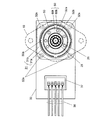
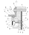
図1は、本発明の実施の形態におけるブラシレスモータ10の断面構造を示す図である。また、図2は、本発明の実施の形態におけるブラシレスモータ10の要部を示す上面図である。また、図3は、図1における円AA箇所の拡大図である。本実施の形態では、ロータがステータの内周側に回転自在に配置されたインナロータ型のブラシレスモータの例を挙げて説明する。
(Embodiment)
FIG. 1 is a diagram showing a cross-sectional structure of a
まず、図1、図2および図3を参照してブラシレスモータ10の全体構成について説明する。
First, the overall configuration of the
図1に示すように、ブラシレスモータ10は、ケーシング13内に、固定子としてのステータ11および回転子としてのロータ12を備えるとともに、モータを駆動制御するための回路基板14をも備えた構成である。さらに、ケーシング13は、モータを構成するステータ11およびロータ12を収納する金属製のモータケース31と、回路基板14を収納する金属製の基板ケース32とで構成されている。
As shown in FIG. 1, the
モータケース31は、上部が円筒形状を成して底面側に開口を有した略カップ形状の収納部31aと、底面側の開口から外周方向に広がる平板部31bとを含む構造となっている。このようなモータケース31内に、図1に示すように、ステータ11およびロータ12が収納されている。さらに、モータケース31の底面側に基板ケース32が配置されている。
The
基板ケース32は、箱形状を成すとともに底面側に開口を有した構造となっており、この内部に回路基板14を収納している。また、詳細な構成については以下で説明するが、モータケース31と基板ケース32とは互いに装着可能なように構成されている。両ケースを互いに装着するため、基板ケース32の天面部に環状立ち上げ部32aを設けている。環状立ち上げ部32aは、基板ケース32の天面部からモータケース31側に、図2に示すような概略環状の形状で突出している。さらに、環状立ち上げ部32aの外周には、弾性部材50を装着している。モータケース31の開口に対して、弾性部材50を挟み込むようにして環状立ち上げ部32aを挿入することで、両ケースが合体する。このようにモータケース31に基板ケース32を装着することで、モータケース31が密封される。さらに、基板ケース32の底面側にケース蓋35を装着することで、基板ケース32が密封される。実際には基板ケース32とケース蓋35の間に弾性部材や接着剤を挟みこんで密封を完全にするが、図1では省略している。同様にモータケース31から回転軸25を導出する部分にはシール部材70を配置して密封している。接続ホルダ37を介して外部配線38を引き出す部分についても弾性部材や接着剤を挟みこんで密封しているが図2では省略している。そして、本実施の形態では、ネジ36によりモータケース31に基板ケース32が固定され、これによって、モータと駆動制御回路とを一体化したブラシレスモータ10が構成される。
The
ステータ11は、ステータコア15に、インシュレータ17を介して相ごとの巻線16を巻回して構成される。本実施の形態では、互いに120度位相が異なるU相、V相、W相とする3つの相に区分した巻線16をステータコア15に巻回している。ステータコア15は、複数枚の鋼板を積層して形成されており、内周側に突出した複数の突極を有している。この突極に、ステータコア15を絶縁するための樹脂製のインシュレータ17を介して巻線16を巻回している。また、ステータコア15の外周側は概略円柱形状であり、その外周がモータケース31の収納部31a内側に面接触して固定されている。すなわち、ステータコア15の外周側と収納部31aの内周側とを略等しい径としている。このようなステータ11の内側には、空隙を介してロータ12が挿入されている。
The
ロータ12は、永久磁石22を保持したロータコア21と、ロータコア21の内周側を貫通する回転軸25と、回転軸25にロータコア21を固着するための固着部材24とで構成される。本実施の形態では、IPM(Interior Permanent Magnet:内部磁石埋込型)タイプのロータ12とした一例を挙げている。すなわち、ロータコア21には、回転軸25と並行するように磁石挿入孔22hが複数設けられており、それぞれの磁石挿入孔22hに永久磁石22を配設している。また、ロータコア21は、複数枚の鋼板を積層して形成されており、中心に回転軸25を配置した円柱形状を成している。そして、ロータコア21の外周面が、空隙を介して、ステータコア15の各突極の先端面と対面している。
The
回転軸25は、ロータコア21の内周側を貫通して両方向に延伸し、両方向に配置されたそれぞれの軸受26によって回転自在に支持される。ここで、一方の軸受26の外周側はモータケース31の天面部で固定され、他方の軸受26の外周側は基板ケース32の天面部で固定されている。基板ケース32側の軸受26を保持するため、基板ケース32には、その天面部からモータケース31側に円環状に突出した環状立ち上げ部32bをさらに設けている。この環状立ち上げ部32bの内周側に軸受26が固定される。
The rotating
回転軸25は、一方の軸受26を固定するモータケース31の天面部からモータケース31の外部へとさらに延伸し、回転駆動するための出力軸として利用される。また、他方の軸受26側へと延伸した回転軸25は、基板ケース32の天面部を貫通し、基板ケース32内まで延伸している。本実施の形態では、この方向に延伸した回転軸25の先端部に、位置検出用磁石80を装着している。
The rotating
以上のように、ロータ12は、両端を軸受26に支持されている。そして、ステータ11は、ロータ12の周囲に環状に配置され、巻線16が巻回されている。
As described above, both ends of the
さらに、このブラシレスモータ10には、各種の回路部品41を実装した回路基板14が基板ケース32の内部に内蔵されている。これら回路部品41によって、電源回路やモータを制御したり駆動したりするための駆動制御回路が構成される。例えば、位置検出用磁石80を装着した回転軸25の先端部に対向するように、位置検出素子41sが回路基板14上に実装されている。これによって、回転動作中の位置検出が行われる。また、図2に示すように、基板ケース32の天面部には接続ホルダ37を配置しており、この接続ホルダ37に電源線や制御信号線などの外部配線38が接続される。そして、接続ホルダ37を介して、例えば電源電力が基板ケース32内の電源回路に供給される。
Further, in the
特に、本実施の形態では、基板ケース32に収納する回路基板14を複数の回路基板で構成するとともに、その中の1つの回路基板にインバータの回路を含めた構成としている。具体的には、回路基板14を、発熱量の多い回路部品41を実装した第1の回路基板14tと発熱量の少ない回路部品41を実装した第2の回路基板14bとの2つの基板に分離した構成としている。
In particular, in the present embodiment, the
第1の回路基板14tには、インバータ用トランジスタなどのパワー素子41pを含む発熱量の多い回路部品41を実装している。すなわち、第1の回路基板14tでは、巻線16を通電駆動するためのインバータを含む駆動回路を主に構成している。特に、インバータ用トランジスタは発熱量が多いとともに、半導体素子なので動作温度が許容限界を超えると破壊に至ることになり、熱に対する保護が重要となる。このため、本実施の形態では、基板ケース32内において、第1の回路基板14tが基板ケース32と熱的に結合するように第1の回路基板14tを配置し、放熱を図っている。具体的には、図3に示すように、第1の回路基板14tは、熱伝導性の良好な絶縁シート43を挟んで、基板ケース32内の天面部に面接触するように装着されている。このような構成により、基板ケース32と第1の回路基板14tとの間の絶縁を確保しながら、第1の回路基板14t上で発生した熱を基板ケース32から効率よく放熱させている。
On the
一方、第2の回路基板14bには、制御用マイコンなどの発熱量の少ない回路部品41を実装している。すなわち、第2の回路基板14bでは、位置検出素子41sの位置検出に基づきモータを回転駆動するためのインバータの制御や速度制御などを行うための制御回路を主に構成している。そして、第2の回路基板14bは、基板ケース32内において、第1の回路基板14tよりも基板ケース32の開口側となるように配置している。本実施の形態では、基板ケース32内の天面部から開口側へと延伸したスペーサ44を介して、第2の回路基板14bを基板ケース32内に保持した構成としている。
On the other hand, a
また、第1の回路基板14tに実装したインバータ用のパワー素子41pによって巻線16を通電駆動するため、本実施の形態では、次のような構成としている。まず、U相、V相、W相それぞれの巻線16の端部が引出線16aとして、ステータ11から基板ケース32の方向に引き出されている。基板ケース32の天面部には複数の孔32hを設けており、これらの孔32hを介してそれぞれの引出線16aが第1の回路基板14tに接続される。さらに、本実施の形態では、巻線16と基板ケース32との間に低熱伝導率の遮熱部材60を配置している。遮熱部材60は、径方向には、環状立ち上げ部32bの外周と環状立ち上げ部32aの内周との間に配置される。すなわち、ブラシレスモータ10は、図2に示すように、モータケース31から内周側に向けて、弾性部材50、環状立ち上げ部32a、遮熱部材60、環状立ち上げ部32b、軸受26、回転軸25の順となるように配置している。
In addition, since the winding 16 is energized and driven by the
また、モータケース31の天面部には、ブラシレスモータ10を相手部材に取付けるために、取付部19が形成されている。さらに、本実施の形態では、取付部19を金属製としモータケース31と一体的に結合した構成としている。これによって、ステータ11の巻線16で発生した熱に対しては、取付部19を介して相手部材へと伝導させて放熱を図るような構成としている。なお、放熱を図るため、取付部19がモータケース31と熱的に結合された状態となるように、モータケース31に取付部19を設けた構成としてもよい。また、モータケース31側の軸受26がこの取付部19によって固定された構成としてもよい。
An
以上のように、ブラシレスモータ10は、ステータ11およびロータ12とともに、巻線16を通電駆動するインバータを備えている。そして、モータケース31が、ステータ11およびロータ12を収納し、ステータ11の外周を保持している。また、基板ケース32が、インバータを構成するパワー素子41pなどの回路部品41を実装した回路基板14を収納している。
As described above, the
さらに、本実施の形態では以下のようにして、ステータ11で発生した熱による駆動回路への影響を抑制するとともに、モータケース31の密封性の向上を図っている。
Further, in the present embodiment, the influence of the heat generated in the
まず、ステータ11での発熱がモータケース31および基板ケース32を伝導して駆動回路に影響することを抑制するため、本実施の形態では、基板ケース32の天面部に突出部32sを複数個設けている。
First, in order to suppress heat generated in the
突出部32sは、基板ケース32の天面部に、天面部の表面からモータケース31側へとわずかに突出するように形成されている。図3では、突出部32sが、基板ケース32の天面部から高さhだけ突出した例を示している。また、図2に示すように、本実施の形態では、モータケース31の平板部31bと対面する基板ケース32の天面部に、円形状に突出する4つの突出部32sを設けた構成例を示している。
The protruding
このような突出部32sを設けることにより、基板ケース32とモータケース31とが突出部32sのみで直接接触した状態で、基板ケース32とモータケース31の平板部31bとが接合される。そして、ネジ36によりケースどうしが固定される。すなわち、このような構成とすることによって、基板ケース32とモータケース31の平板部31bとの接触面積は、突出部32sを設けない場合に比べて非常に小さくなる。
By providing such a protruding
本実施の形態では、突出部32sを設けて、ケースどうしの接触面積を極力小さくし、これによって、ステータ11の巻線16で発生した熱が、ステータコア15、モータケース31、基板ケース32、絶縁シート43を介して、第1の回路基板14t上のパワー素子41pなどに伝導していくことを抑制している。また、基板ケース32とモータケース31とを、突出部32sを介した金属どうしの接合とすることで、接合強度の劣化を抑えている。
In the present embodiment, the
なお、以上の説明は基板ケース32とモータケース31の回転軸方向の接合状態について説明したが、具体的には半径方向にも同様に突出部を設けて基板ケース32とモータケース31どうしが直接接触した状態で接触面積が極力小さくなるような構造としている。半径方向の接合状態の詳細は後述する。
In the above description, the joint state of the
また、以上の説明では、基板ケース32の天面部に突出部32sを設けた例を挙げて説明したが、モータケース31側にこのような突出部を設けてもよい。図4は、モータケース31に円環状の突出部31sを設けた構成を示す拡大図である。モータケース31の平板部31bに、図4に示すような円環状の突出部31sを基板ケース32と対面する側に複数設ける。このような構成によっても、基板ケース32とモータケース31とは円環状の突出部31sのみで接触するため、巻線16で発生した熱がパワー素子41pなどに伝導することを抑制できる。すなわち、このような表面から突出した突出部は、基板ケース32とモータケース31とのいずれかの表面に設けた構成であればよい。
In the above description, the example in which the
また、本実施の形態では、円形状に突出する4つの突出部32sを設けた例を挙げているが、突出部32sの形状や個数はこれに限定されず、基板ケース32とモータケース31とがバランスよく接合できるとともに、両ケースの接触面積を小さくできる形状や個数であればよい。
In the present embodiment, an example in which four projecting
次に、ステータ11の巻線16から輻射された熱やモータケース31内で対流する熱が駆動回路へ影響することを抑制するため、本実施の形態では、低熱伝導率の遮熱部材60を、巻線16と基板ケース32との間に配置している。
Next, in order to suppress the heat radiated from the winding 16 of the
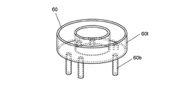
図5は、遮熱部材60の斜視図である。図5に示すように、遮熱部材60は、本体部60tとともに、本体部60tから筒状に延伸した複数の案内部60bを有している。案内部60bは、図3に示すように、基板ケース32の孔32hにそれぞれ挿入され、これによって、遮熱部材60が基板ケース32の天面部とステータ11との間に装着される。そして、図3に示すように、巻線16の端部となる引出線16aが案内部60b内を通って第1の回路基板の引出線挿入孔14thへと導かれる。本実施の形態では、このような遮熱部材60を設けることにより、引出線16aと基板ケース32との間の絶縁を図りながら、引出線16aを第1の回路基板14tへと案内している。そして、遮熱部材60の本体部60tによって、モータケース31で発生した熱を遮断するように構成している。すなわち、巻線16で発生した熱が輻射され、基板ケース32の天面部を介して第1の回路基板14tへと伝導することを抑制している。特に、遮熱部材60の案内部60bを基板ケース32の孔32hに挿入するのみで第1の回路基板14tの引出線挿入孔14thに引出線16aを挿通することができるため、簡単な作業でモータの組立をすることができる。
FIG. 5 is a perspective view of the
次に、モータケース31の密封性を確保するために、本実施の形態では、モータケース31と基板ケース32との間に弾性を有する弾性部材50を挟み込んだ構成としている。
Next, in order to ensure the sealing performance of the
図6は、本発明の実施の形態におけるブラシレスモータ10の要部の分解斜視図である。
FIG. 6 is an exploded perspective view of a main part of the
図6に示すように、基板ケース32の天面部に、環状立ち上げ部32aを設けている。また、弾性部材50は、例えばOリングであり、ゴムなどの弾性材料で形成されて環状の形状を成している。図6では、断面が円となる弾性部材50の一例を挙げている。弾性部材50は、その内径が環状立ち上げ部32aに形成された部材装着溝30mの溝径と略等しくなるように形成している。そして、このような弾性部材50は、部材装着溝30mに装着される。
As shown in FIG. 6, an annular rising
より具体的には、次のような構成としている。まず、図6に示すように、環状立ち上げ部32aには、複数の突出部30aと部材装着溝30mを設けている。図6では、周方向に等間隔で4つの突出部30aを設けた一例を示している。突出部30aは、下側突出部30bと、上側突出部30tとで構成されている。下側突出部30bおよび上側突出部30tは、図6に示すように、環状立ち上げ部32aの外周面30cからさらに外周方向に向けて突起している(図6では判りやすいように突出量、形状を誇張して描いているが実際には0.1mm前後のわずかな突出量、1mm前後のわずかな幅である)。図6では、環状立ち上げ部32a基部の外周面30cから外周方向に高さwpだけ突起した例を示している。また、下側突出部30bと上側突出部30tの間には部材装着溝30mが設けられており、このような部材装着溝30mに対して、弾性部材50を広げながら装着する。このように弾性部材50を装着した環状立ち上げ部32aの外周に、モータケース31底部の開口を装着することによって、モータケース31と基板ケース32との一体化が図られる。
More specifically, the configuration is as follows. First, as shown in FIG. 6, a plurality of projecting
図7は、環状立ち上げ部32a、弾性部材50およびモータケース31の各サイズの詳細な関係を示す図である。
FIG. 7 is a diagram showing a detailed relationship between the sizes of the annular rising
図7は弾性部材50を部材装着溝30mに装着したとき、弾性部材50が部材装着溝30mの溝の底面から外周方向に向けて高さwrだけ突出した一例を示している。本実施の形態では、図7に示すように、高さwrが部材装着溝30mの深さwmよりも大きくなるように、弾性部材50の大きさを設定している。
FIG. 7 shows an example in which when the
また、図7では、部材装着溝30mの溝径dcと、環状立ち上げ部32aの突出部30aを含めた径dpと、環状立ち上げ部32aに弾性部材50を装着したときの径deと、モータケース31底部の開口の径dmとの大きさ関係を示している。ここで、径dc、径dp、径deの関係は上述したことより、図7に示すように、de>dp>dcとなる。そして、本実施の形態では、モータケース31底部の開口の径dmを径dpよりわずかに大きく、かつ径deよりも小さくなるように構成している。このような大きさ関係となるように、モータケース31底部の開口の径、環状立ち上げ部32aの各部のサイズ、および弾性部材50のサイズを設定することにより、弾性部材50が収縮した状態で、モータケース31の収納部31a内周と部材装着溝30mとの間に、弾性部材50を挟み込む構造となる。このような構造により、モータケース31を密閉した構成となり、弾性部材50によって水の浸入を防ぐような水密構造を実現している。
In FIG. 7, the groove diameter dc of the
また、弾性部材50は、例えばゴムなどであり、通常熱伝導性が低い。そして、基板ケース32の環状立ち上げ部32aとモータケース31の収納部31aとが、直接に接触せずに、熱伝導性の低い弾性部材50を介して接触するような構造としている。このように、本実施の形態では、弾性部材50を利用して水密構造にするとともに、弾性部材50をステータ11から第1の回路基板14tへの熱伝導抑制にも利用している。すなわち、基板ケース32とモータケース31の半径方向の接合状態は熱伝導性の低い弾性部材50を介した水密状態の接触と突出部30a先端の非常に小さな面積のみにより直接に接触する構成としている。このため、ステータ11の巻線16で発生した熱が、ステータコア15、モータケース31、基板ケース32、絶縁シート43を介して、第1の回路基板14t上のパワー素子41pなどに伝導していくことを抑制している。
Moreover, the
また、突出部30aによる金属どうしの直接接触でモータケース31と基板ケース32を接合した構成であるため、熱伝導を防止するために低熱伝導率の樹脂などを介した接合に比べて、組み付け精度を確保できる。このため、両ケースに分けて軸受を配置しても、両軸受の同軸度、すなわち両軸受間の位置精度を確保できる。
In addition, since the
以上説明したように、本実施の形態のブラシレスモータ10は、基板ケース32とモータケース31とを突出部32sおよび32aのみで直接に接触させて、基板ケース32とモータケース31とを接合した構成である。本実施の形態では、このような構成とすることにより、ステータ11の巻線16で発生した熱が、第1の回路基板14t上のパワー素子41pなどに伝導していくことを抑制している。また、突出部32sおよび32aによる金属どうしの接触で両ケースを接合した構成であるため、樹脂などを介した接合に比べて組み付け精度を確保できるため、両ケースに分けて軸受を配置しても、両軸受の同軸度、すなわち両軸受間の位置精度を確保できる。さらに接合強度を確保できるため耐振動性を高めることができる。
As described above, the
さらに、本実施の形態のブラシレスモータ10は、モータケース31の収納部31aの開口に、弾性部材50を挟み込むようにして、弾性部材50を装着した環状立ち上げ部32aを挿入した構成を含む。本実施の形態では、このような構成とすることにより、巻線16で発生した熱が第1の回路基板14tに伝導することを抑制しながら、水密構造のモータを実現している。
Further, the
さらに、本実施の形態のブラシレスモータ10は、巻線16と基板ケース32との間に、低熱伝導率の遮熱部材60を配置した構成を含む。遮熱部材60は、巻線16の端末を回路基板14に案内および絶縁する機能を有するとともに、低熱伝導率の特性によって巻線16で発生した熱が第1の回路基板14tへと伝導することを抑制している。このような遮熱部材60は案内部60bを基板ケース32の孔32hに挿入するのみで第1の回路基板14tの引出線挿入孔14thに引出線16aを挿通することができるため、簡単な作業でモータの組立をすることができる。
Further, the
以上、本発明のブラシレスモータは、モータとインバータとを一体化するとともに、モータを収納するモータケースとインバータを収納する基板ケースとを備える。そして、基板ケースとモータケースとのいずれかの表面に、表面から突出した突出部を設け、基板ケースとモータケースとを突出部のみで接触させて、基板ケースとモータケースとを接合した構成である。これにより、両ケースの接合強度を確保しながら、巻線で発生した熱がインバータなどに伝導していくことを抑制でき、高温環境での使用も可能となる。 As described above, the brushless motor of the present invention integrates the motor and the inverter, and includes the motor case that houses the motor and the substrate case that houses the inverter. Then, a protruding part protruding from the surface is provided on either surface of the substrate case and the motor case, the substrate case and the motor case are brought into contact with each other only by the protruding part, and the substrate case and the motor case are joined. is there. Thereby, it can suppress that the heat | fever generate | occur | produced with the coil | winding conducts to an inverter etc., ensuring the joining strength of both cases, and the use in a high temperature environment is also attained.
また、本発明のブラシレスモータは、回路基板を複数の回路基板で構成し、インバータの回路を含めた回路基板を、基板ケースと熱的に結合するように基板ケース内に配置した構成である。これにより、インバータの回路を含めた回路基板で発生した熱を、基板ケースから効率よく放熱させることができる。 In the brushless motor of the present invention, the circuit board is constituted by a plurality of circuit boards, and the circuit board including the inverter circuit is arranged in the board case so as to be thermally coupled to the board case. Thereby, the heat generated in the circuit board including the inverter circuit can be efficiently radiated from the board case.
また、本発明のブラシレスモータは、ブラシレスモータを相手部材に取付けるための取付部を、モータケースと一体的または熱的に結合された状態で形成した構成である。これにより、巻線で発生した熱に対して相手部材へと伝導させることができ、巻線での熱がインバータへ影響することをさらに抑えることができる。 The brushless motor of the present invention has a configuration in which an attachment portion for attaching the brushless motor to the mating member is formed in a state of being integrally or thermally coupled to the motor case. Thereby, the heat generated in the winding can be conducted to the counterpart member, and the influence of the heat in the winding on the inverter can be further suppressed.
また、本発明のブラシレスモータは、モータケースの開口に、弾性部材を挟み込むようにして、弾性部材を装着した環状立ち上げ部を挿入した構成である。これにより、巻線での熱がインバータに伝導することを抑制しながら、水密構造を実現できる。 Further, the brushless motor of the present invention has a configuration in which an annular start-up portion equipped with an elastic member is inserted into the opening of the motor case so as to sandwich the elastic member. Thereby, a watertight structure can be realized while suppressing heat in the winding from being conducted to the inverter.
また、本発明のブラシレスモータは、巻線と基板ケースとの間に低熱伝導率の遮熱板を配置した構成である。これにより、作業効率を向上させながら遮熱効果を実現できる。 Further, the brushless motor of the present invention has a configuration in which a heat shield having a low thermal conductivity is disposed between the winding and the substrate case. Thereby, the heat shielding effect can be realized while improving the working efficiency.
なお、以上、IPMタイプのロータとした一例を挙げて説明したが、磁石をロータコアの表面に配設したSPM(Surface Permanent Magnet:表面磁石貼付型)タイプのロータであってもよい。 In the above, an example of an IPM type rotor has been described, but an SPM (Surface Permanent Magnet) type rotor in which magnets are arranged on the surface of the rotor core may be used.
本発明のブラシレスモータは、水密構造を有するとともに、高温環境下での動作に適したインバータ一体型モータであるため、車両に搭載する電装用のモータとして好適である。さらに、本発明のブラシレスモータは、電気機器において高温環境下や水周りで使用されるモータとしても有用である。 The brushless motor of the present invention has a watertight structure and is an inverter-integrated motor suitable for operation in a high temperature environment, and thus is suitable as an electric motor mounted on a vehicle. Furthermore, the brushless motor of the present invention is also useful as a motor used in electrical equipment in a high temperature environment or around water.
10 ブラシレスモータ
11 ステータ
12 ロータ
13 ケーシング
14 回路基板
14t 第1の回路基板
14th 第1の回路基板の引出線挿入孔
14b 第2の回路基板
15 ステータコア
16 巻線
16a 引出線
17 インシュレータ
19 取付部
21 ロータコア
22 永久磁石
22h 磁石挿入孔
24 固着部材
25 回転軸
26 軸受
30a 突出部
30b 下側突出部
30m 部材装着溝
30t 上側突出部
31 モータケース
31a 収納部
31b 平板部
31s,32s 突出部
32 基板ケース
32a,32b 環状立ち上げ部
35 ケース蓋
36 ネジ
37 接続ホルダ
38 外部配線
41 回路部品
41p パワー素子
41s 位置検出素子
43 絶縁シート
44 スペーサ
50 弾性部材
60 遮熱部材
60b 案内部
60t 本体部
70 シール部材
80 位置検出用磁石
DESCRIPTION OF
Claims (5)
前記回転子の周囲に環状に配置され、巻線が巻回された固定子と、
前記巻線を通電駆動するインバータとを備えたブラシレスモータであって、
前記回転子および前記固定子を収納し、前記固定子の外周を保持するモータケースと、
前記インバータを構成する回路部品および位置検出素子を実装した回路基板ならびに前記回転子に装着した位置検出用磁石を収納する基板ケースとを備え、
前記基板ケースと前記モータケースとの少なくともいずれか一方の表面に、この基板ケースとこのモータケースとの接触面積を小さくするための突起状で前記表面から突出した突出部を設け、前記基板ケースと前記モータケースとを前記突出部のみで接触させた状態で前記基板ケースと前記モータケースとを接合し、
前記回転子の両端を支持する前記軸受の一方は、前記モータケースによって保持され、
前記回転子の両端を支持する前記軸受の他方は、前記基板ケースによって保持されていることを特徴とするブラシレスモータ。 A rotor with both ends of the rotating shaft supported by bearings;
A stator arranged in a ring around the rotor and wound with windings;
A brushless motor comprising an inverter that energizes and drives the winding;
A motor case for housing the rotor and the stator and holding an outer periphery of the stator;
A circuit board on which the circuit components constituting the inverter and the position detection element are mounted, and a board case for storing a position detection magnet mounted on the rotor ;
On at least one surface of the substrate case and the motor case, a protruding portion protruding from the surface with protruding order to reduce the contact area between the substrate case and the motor case is provided, and the board case wherein bonding the substrate case and the motor case in a state in which the said motor casing is brought into contact only with the projecting portion,
One of the bearings supporting both ends of the rotor is held by the motor case,
The other of the bearings that support both ends of the rotor is held by the substrate case .
前記基板ケースは、複数の前記突出部のいくつかまたはすべてがこの基板ケースの表面から環状に突出し、この環状に突出した突出部と環状の溝により形成した環状立ち上げ部を有し、
前記環状の溝に環状の弾性部材を装着し、
前記収納部の開口に、前記弾性部材を挟み込んだ状態で、前記弾性部材を装着した前記環状立ち上げ部が挿入されていることを特徴とする請求項1に記載のブラシレスモータ。 The motor case has a cup-shaped storage part,
The substrate case has from some or all of the surface of the board case of the protruding portions of the multiple projecting annular, the annular raised portion formed by the groove of the projection and the annular projecting annular,
An annular elastic member is attached to the annular groove,
Wherein the opening of the storage portion, the brushless motor according to claim 1, wherein an elastic member I write sandwiched state, the annular raised portion fitted with the elastic member is characterized in that it is inserted.
Priority Applications (1)
| Application Number | Priority Date | Filing Date | Title |
|---|---|---|---|
| JP2011197965A JP5934879B2 (en) | 2011-09-12 | 2011-09-12 | Brushless motor |
Applications Claiming Priority (1)
| Application Number | Priority Date | Filing Date | Title |
|---|---|---|---|
| JP2011197965A JP5934879B2 (en) | 2011-09-12 | 2011-09-12 | Brushless motor |
Publications (2)
| Publication Number | Publication Date |
|---|---|
| JP2013062899A JP2013062899A (en) | 2013-04-04 |
| JP5934879B2 true JP5934879B2 (en) | 2016-06-15 |
Family
ID=48187091
Family Applications (1)
| Application Number | Title | Priority Date | Filing Date |
|---|---|---|---|
| JP2011197965A Active JP5934879B2 (en) | 2011-09-12 | 2011-09-12 | Brushless motor |
Country Status (1)
| Country | Link |
|---|---|
| JP (1) | JP5934879B2 (en) |
Cited By (1)
| Publication number | Priority date | Publication date | Assignee | Title |
|---|---|---|---|---|
| CN105322722A (en) * | 2014-07-31 | 2016-02-10 | 株式会社电装 | Drive device and electric power steering device including drive device |
Families Citing this family (8)
| Publication number | Priority date | Publication date | Assignee | Title |
|---|---|---|---|---|
| JP2015053829A (en) * | 2013-09-09 | 2015-03-19 | 日立オートモティブシステムズ株式会社 | Electric fluid pump |
| JP6464584B2 (en) * | 2014-07-10 | 2019-02-06 | 富士電機株式会社 | Permanent magnet synchronous motor rotor, permanent magnet synchronous motor and permanent magnet synchronous motor device |
| JP6855845B2 (en) * | 2017-03-03 | 2021-04-07 | 日本電産トーソク株式会社 | Motor and electric oil pump |
| WO2019208073A1 (en) * | 2018-04-24 | 2019-10-31 | 日本電産トーソク株式会社 | Motor unit and electric oil pump |
| JP7331542B2 (en) | 2018-09-28 | 2023-08-23 | ニデックパワートレインシステムズ株式会社 | electric pump device |
| JP2020076387A (en) * | 2018-11-09 | 2020-05-21 | 日本電産トーソク株式会社 | Electric oil pump |
| DE102020203260A1 (en) * | 2019-03-28 | 2020-10-01 | Kabushiki Kaisha Toyota Jidoshokki | ELECTRIC COMPRESSOR |
| JP2020171084A (en) * | 2019-04-01 | 2020-10-15 | パナソニックIpマネジメント株式会社 | motor |
Family Cites Families (2)
| Publication number | Priority date | Publication date | Assignee | Title |
|---|---|---|---|---|
| JPS59165941A (en) * | 1983-03-11 | 1984-09-19 | Hitachi Ltd | Inverter drive rotary electric machine |
| JP4597312B2 (en) * | 2000-05-12 | 2010-12-15 | 住友重機械工業株式会社 | Control motor and speed control device mounting structure for control motor |
-
2011
- 2011-09-12 JP JP2011197965A patent/JP5934879B2/en active Active
Cited By (2)
| Publication number | Priority date | Publication date | Assignee | Title |
|---|---|---|---|---|
| CN105322722A (en) * | 2014-07-31 | 2016-02-10 | 株式会社电装 | Drive device and electric power steering device including drive device |
| CN105322722B (en) * | 2014-07-31 | 2019-04-09 | 株式会社电装 | Driving device and electric power steering apparatus including driving device |
Also Published As
| Publication number | Publication date |
|---|---|
| JP2013062899A (en) | 2013-04-04 |
Similar Documents
| Publication | Publication Date | Title |
|---|---|---|
| JP5934879B2 (en) | Brushless motor | |
| JP4986258B2 (en) | Electric tool | |
| US9077230B2 (en) | Electric motor with heat dissipating device | |
| EP2549629B1 (en) | Rotating electrical machine | |
| TWI643433B (en) | Rotary electric machine | |
| JP5722644B2 (en) | Rotating electric machine | |
| US20100096938A1 (en) | Blower motor | |
| WO2017033917A1 (en) | Motor | |
| JP2013167243A (en) | Electric pump | |
| JP4602392B2 (en) | Inner rotor type brushless motor | |
| US20180338374A1 (en) | Motor, circuit board, and engine cooling module including the motor | |
| WO2016103605A1 (en) | Motor and electric tool equipped with same | |
| JP6882884B2 (en) | motor | |
| US20100090554A1 (en) | Outer-rotor brushless motor | |
| JP2014138489A (en) | Motor with inverter | |
| JP6047023B2 (en) | Electric pump | |
| JP2021048688A (en) | Motor, and electrically-driven pump | |
| JP2017184295A (en) | Dynamo-electric machine | |
| JP5420040B1 (en) | Rotating electric machine | |
| JP6302023B2 (en) | Rotating electric machine | |
| JP7249590B2 (en) | Electric tool motors and electric tools | |
| JP6255566B2 (en) | Electric motors and electrical equipment | |
| JP6608304B2 (en) | Motor and motor with reduction gear | |
| JP2017147857A (en) | Motor with controller and motor with speed reducer | |
| JP6961990B2 (en) | Motor unit |
Legal Events
| Date | Code | Title | Description |
|---|---|---|---|
| A621 | Written request for application examination |
Free format text: JAPANESE INTERMEDIATE CODE: A621 Effective date: 20140826 |
|
| RD01 | Notification of change of attorney |
Free format text: JAPANESE INTERMEDIATE CODE: A7421 Effective date: 20140912 |
|
| A711 | Notification of change in applicant |
Free format text: JAPANESE INTERMEDIATE CODE: A711 Effective date: 20141007 |
|
| A977 | Report on retrieval |
Free format text: JAPANESE INTERMEDIATE CODE: A971007 Effective date: 20150529 |
|
| A131 | Notification of reasons for refusal |
Free format text: JAPANESE INTERMEDIATE CODE: A131 Effective date: 20150630 |
|
| A521 | Written amendment |
Free format text: JAPANESE INTERMEDIATE CODE: A523 Effective date: 20150828 |
|
| TRDD | Decision of grant or rejection written | ||
| A01 | Written decision to grant a patent or to grant a registration (utility model) |
Free format text: JAPANESE INTERMEDIATE CODE: A01 Effective date: 20160216 |
|
| A61 | First payment of annual fees (during grant procedure) |
Free format text: JAPANESE INTERMEDIATE CODE: A61 Effective date: 20160229 |
|
| R151 | Written notification of patent or utility model registration |
Ref document number: 5934879 Country of ref document: JP Free format text: JAPANESE INTERMEDIATE CODE: R151 |