JP5933723B2 - Ablation planning using affected area feedback - Google Patents
Ablation planning using affected area feedback Download PDFInfo
- Publication number
- JP5933723B2 JP5933723B2 JP2014530353A JP2014530353A JP5933723B2 JP 5933723 B2 JP5933723 B2 JP 5933723B2 JP 2014530353 A JP2014530353 A JP 2014530353A JP 2014530353 A JP2014530353 A JP 2014530353A JP 5933723 B2 JP5933723 B2 JP 5933723B2
- Authority
- JP
- Japan
- Prior art keywords
- ablation
- tumor
- profile
- contour
- main
- Prior art date
- Legal status (The legal status is an assumption and is not a legal conclusion. Google has not performed a legal analysis and makes no representation as to the accuracy of the status listed.)
- Active
Links
Images


Classifications
-
- A—HUMAN NECESSITIES
- A61—MEDICAL OR VETERINARY SCIENCE; HYGIENE
- A61B—DIAGNOSIS; SURGERY; IDENTIFICATION
- A61B34/00—Computer-aided surgery; Manipulators or robots specially adapted for use in surgery
- A61B34/10—Computer-aided planning, simulation or modelling of surgical operations
-
- A—HUMAN NECESSITIES
- A61—MEDICAL OR VETERINARY SCIENCE; HYGIENE
- A61B—DIAGNOSIS; SURGERY; IDENTIFICATION
- A61B34/00—Computer-aided surgery; Manipulators or robots specially adapted for use in surgery
- A61B34/25—User interfaces for surgical systems
-
- G—PHYSICS
- G06—COMPUTING; CALCULATING OR COUNTING
- G06T—IMAGE DATA PROCESSING OR GENERATION, IN GENERAL
- G06T19/00—Manipulating 3D models or images for computer graphics
- G06T19/20—Editing of 3D images, e.g. changing shapes or colours, aligning objects or positioning parts
-
- A—HUMAN NECESSITIES
- A61—MEDICAL OR VETERINARY SCIENCE; HYGIENE
- A61B—DIAGNOSIS; SURGERY; IDENTIFICATION
- A61B18/00—Surgical instruments, devices or methods for transferring non-mechanical forms of energy to or from the body
- A61B18/04—Surgical instruments, devices or methods for transferring non-mechanical forms of energy to or from the body by heating
- A61B18/12—Surgical instruments, devices or methods for transferring non-mechanical forms of energy to or from the body by heating by passing a current through the tissue to be heated, e.g. high-frequency current
- A61B18/14—Probes or electrodes therefor
- A61B18/1477—Needle-like probes
-
- A—HUMAN NECESSITIES
- A61—MEDICAL OR VETERINARY SCIENCE; HYGIENE
- A61B—DIAGNOSIS; SURGERY; IDENTIFICATION
- A61B18/00—Surgical instruments, devices or methods for transferring non-mechanical forms of energy to or from the body
- A61B18/18—Surgical instruments, devices or methods for transferring non-mechanical forms of energy to or from the body by applying electromagnetic radiation, e.g. microwaves
- A61B18/1815—Surgical instruments, devices or methods for transferring non-mechanical forms of energy to or from the body by applying electromagnetic radiation, e.g. microwaves using microwaves
-
- A—HUMAN NECESSITIES
- A61—MEDICAL OR VETERINARY SCIENCE; HYGIENE
- A61B—DIAGNOSIS; SURGERY; IDENTIFICATION
- A61B18/00—Surgical instruments, devices or methods for transferring non-mechanical forms of energy to or from the body
- A61B2018/00571—Surgical instruments, devices or methods for transferring non-mechanical forms of energy to or from the body for achieving a particular surgical effect
- A61B2018/00577—Ablation
-
- A—HUMAN NECESSITIES
- A61—MEDICAL OR VETERINARY SCIENCE; HYGIENE
- A61B—DIAGNOSIS; SURGERY; IDENTIFICATION
- A61B18/00—Surgical instruments, devices or methods for transferring non-mechanical forms of energy to or from the body
- A61B18/02—Surgical instruments, devices or methods for transferring non-mechanical forms of energy to or from the body by cooling, e.g. cryogenic techniques
- A61B2018/0293—Surgical instruments, devices or methods for transferring non-mechanical forms of energy to or from the body by cooling, e.g. cryogenic techniques using an instrument interstitially inserted into the body, e.g. needle
-
- A—HUMAN NECESSITIES
- A61—MEDICAL OR VETERINARY SCIENCE; HYGIENE
- A61B—DIAGNOSIS; SURGERY; IDENTIFICATION
- A61B18/00—Surgical instruments, devices or methods for transferring non-mechanical forms of energy to or from the body
- A61B18/04—Surgical instruments, devices or methods for transferring non-mechanical forms of energy to or from the body by heating
- A61B18/12—Surgical instruments, devices or methods for transferring non-mechanical forms of energy to or from the body by heating by passing a current through the tissue to be heated, e.g. high-frequency current
- A61B18/14—Probes or electrodes therefor
- A61B2018/1405—Electrodes having a specific shape
- A61B2018/1425—Needle
-
- A—HUMAN NECESSITIES
- A61—MEDICAL OR VETERINARY SCIENCE; HYGIENE
- A61B—DIAGNOSIS; SURGERY; IDENTIFICATION
- A61B18/00—Surgical instruments, devices or methods for transferring non-mechanical forms of energy to or from the body
- A61B18/18—Surgical instruments, devices or methods for transferring non-mechanical forms of energy to or from the body by applying electromagnetic radiation, e.g. microwaves
- A61B18/1815—Surgical instruments, devices or methods for transferring non-mechanical forms of energy to or from the body by applying electromagnetic radiation, e.g. microwaves using microwaves
- A61B2018/1869—Surgical instruments, devices or methods for transferring non-mechanical forms of energy to or from the body by applying electromagnetic radiation, e.g. microwaves using microwaves with an instrument interstitially inserted into the body, e.g. needles
-
- A—HUMAN NECESSITIES
- A61—MEDICAL OR VETERINARY SCIENCE; HYGIENE
- A61B—DIAGNOSIS; SURGERY; IDENTIFICATION
- A61B34/00—Computer-aided surgery; Manipulators or robots specially adapted for use in surgery
- A61B34/10—Computer-aided planning, simulation or modelling of surgical operations
- A61B2034/101—Computer-aided simulation of surgical operations
- A61B2034/102—Modelling of surgical devices, implants or prosthesis
- A61B2034/104—Modelling the effect of the tool, e.g. the effect of an implanted prosthesis or for predicting the effect of ablation or burring
-
- A—HUMAN NECESSITIES
- A61—MEDICAL OR VETERINARY SCIENCE; HYGIENE
- A61B—DIAGNOSIS; SURGERY; IDENTIFICATION
- A61B34/00—Computer-aided surgery; Manipulators or robots specially adapted for use in surgery
- A61B34/10—Computer-aided planning, simulation or modelling of surgical operations
- A61B2034/107—Visualisation of planned trajectories or target regions
-
- A—HUMAN NECESSITIES
- A61—MEDICAL OR VETERINARY SCIENCE; HYGIENE
- A61B—DIAGNOSIS; SURGERY; IDENTIFICATION
- A61B34/00—Computer-aided surgery; Manipulators or robots specially adapted for use in surgery
- A61B34/25—User interfaces for surgical systems
- A61B2034/252—User interfaces for surgical systems indicating steps of a surgical procedure
-
- A—HUMAN NECESSITIES
- A61—MEDICAL OR VETERINARY SCIENCE; HYGIENE
- A61B—DIAGNOSIS; SURGERY; IDENTIFICATION
- A61B34/00—Computer-aided surgery; Manipulators or robots specially adapted for use in surgery
- A61B34/25—User interfaces for surgical systems
- A61B2034/258—User interfaces for surgical systems providing specific settings for specific users
-
- A—HUMAN NECESSITIES
- A61—MEDICAL OR VETERINARY SCIENCE; HYGIENE
- A61B—DIAGNOSIS; SURGERY; IDENTIFICATION
- A61B90/00—Instruments, implements or accessories specially adapted for surgery or diagnosis and not covered by any of the groups A61B1/00 - A61B50/00, e.g. for luxation treatment or for protecting wound edges
- A61B90/36—Image-producing devices or illumination devices not otherwise provided for
- A61B90/37—Surgical systems with images on a monitor during operation
- A61B2090/374—NMR or MRI
-
- A—HUMAN NECESSITIES
- A61—MEDICAL OR VETERINARY SCIENCE; HYGIENE
- A61B—DIAGNOSIS; SURGERY; IDENTIFICATION
- A61B90/00—Instruments, implements or accessories specially adapted for surgery or diagnosis and not covered by any of the groups A61B1/00 - A61B50/00, e.g. for luxation treatment or for protecting wound edges
- A61B90/36—Image-producing devices or illumination devices not otherwise provided for
- A61B90/37—Surgical systems with images on a monitor during operation
- A61B2090/376—Surgical systems with images on a monitor during operation using X-rays, e.g. fluoroscopy
-
- A—HUMAN NECESSITIES
- A61—MEDICAL OR VETERINARY SCIENCE; HYGIENE
- A61B—DIAGNOSIS; SURGERY; IDENTIFICATION
- A61B2218/00—Details of surgical instruments, devices or methods for transferring non-mechanical forms of energy to or from the body
Description
本発明は、腫瘍を目標とするアブレーション(ablation)計画に関する。より特定的には、腫瘍を目標とするアブレーション計画、腫瘍を目標とするアブレーションのための医療システム、腫瘍を目標とするアブレーション計画のための方法に関する。コンピュータープログラムエレメント、および、コンピューターで読取り可能な媒体も同様である。 The present invention relates to ablation schemes targeting tumors. More specifically, it relates to an ablation plan targeting a tumor, a medical system for ablation targeting a tumor, and a method for an ablation plan targeting a tumor. The same applies to computer program elements and computer readable media.
画像ガイド付き低侵襲腫瘍アブレーション技術は、例えば、切除不能、もしくは、切開できない種々の腫瘍に対する実行可能な処置のオプションとなっている。腫瘍アブレーションの目的は、腫瘍細胞を完全に死滅させることである。従って、インターベンション(intervension)以前の計画段階の最中にアブレーション領域の大きさ、形状、および、位置が検討される。例えば、米国特許出願第2010/0063496A1号は、腫瘍アブレーション手順の計画方法について記載している。しかしながら、腫瘍を目標とするアブレーション計画は、しばしば自由裁量で計画され、計画手順の結果はオペレーターによって異なることがある。 Image-guided minimally invasive tumor ablation techniques have become a viable treatment option for various tumors that cannot be resected or that cannot be incised, for example. The purpose of tumor ablation is to completely kill tumor cells. Therefore, the size, shape, and position of the ablation region are considered during the planning phase prior to the intervention. For example, US Patent Application 2010 / 0063496A1 describes a method for planning a tumor ablation procedure. However, tumor-targeted ablation plans are often planned at a discretion and the results of the planning procedure may vary from operator to operator.
例えば、国際公開第2011/080666号は、患者の中に位置する対象ボリュームを表す画像を生成するための画像システムについて開示している。分割ユニットは、アブレーション治療を受ける対象ボリュームについて計画対象ボリュームに分割する。計画プロセッサは、一つまたはそれ以上のアブレーション領域についてアブレーション計画を生成し、アブレーション治療を行う計画対象ボリュームの全体をカバーする。それぞれのアブレーション領域は既定のアブレーションボリュームを有しており、既定のアブレーション領域は、アブレーションの最中にアブレーションプローブを移動することによって決定される。ロボットアセンブリーが、アブレーションプローブを非定常的な動作パスに沿ってガイドし、または、コントロールする。動作パスは、既定のアブレーション領域に従って対象ボリュームに対してアブレーション治療を適用するための軌道、速度及び/又は加速度、および、回転によって定められる。 For example, WO 2011/080666 discloses an imaging system for generating an image representing a volume of interest located in a patient. The dividing unit divides the target volume that receives the ablation treatment into the planning target volume. The planning processor generates an ablation plan for one or more ablation regions and covers the entire planning volume to be ablated. Each ablation area has a predetermined ablation volume, which is determined by moving the ablation probe during ablation. A robot assembly guides or controls the ablation probe along a non-stationary motion path. The motion path is defined by the trajectory, velocity and / or acceleration, and rotation for applying the ablation treatment to the target volume according to a predetermined ablation region.
このように、促進され、改善された画像ベースの計画方法を提供する必要がある。 Thus, there is a need to provide an improved and improved image-based planning method.
本発明の目的は、本願の独立請求項に係る技術的事項によって解決される。さらなる実施例は、従属請求項の中に包含されている。 The object of the present invention is solved by the technical matters according to the independent claims of the present application. Further embodiments are contained in the dependent claims.
以降に説明される本発明の態様は、また、腫瘍を目標とするアブレーション計画のためのプランニング装置、医療システム、方法、コンピュータープログラムエレメント及びコンピューターで読取り可能な媒体に対しても適用可能であることに留意すべきである。 Aspects of the invention described below are also applicable to planning devices, medical systems, methods, computer program elements and computer readable media for ablation planning targeting tumors. Should be noted.
本発明の第1の態様に従って、腫瘍を目標とするアブレーション計画のためのプランニング装置が提供される。装置は、処理ユニットと;インターフェイスユニットと;ディスプレイユニットと、を含んでいる。前記インターフェイスユニットは、アブレーション手順で扱われるべき3次元データセットにおける少なくとも一つの区分化された腫瘍を提供し、かつ、既定のアブレーションプロファイルを提供するように構成されている。前記処理ユニットは、前記区分化された腫瘍の輪郭を生成し、既定のアブレーションプロファイルを少なくとも一つの区分化された腫瘍の少なくとも一部と重ね合わせ、重なり合った領域を特定し、変更された重なり合い領域を生成するために少なくとも重なり合い領域の一部について規定の安全ファクターを適用するように構成されている。前記処理ユニットは、さらに、変更された重なり合い領域の外側に配置された重なり合い領域の部分を主要重なり合い部分として決定するように構成されている。前記ディスプレイユニットは、前記区分化された輪郭を表示し、少なくとも一つの前記区分化された腫瘍の少なくとも一部と重なり合った前記既定のアブレーションプロファイルを表示し、かつ、仮想計画アブレーション結果として、前記輪郭と前記アブレーションプロファイルに関連して前記主要重なり合い部分を表示するように構成されている。 In accordance with a first aspect of the present invention, a planning device for ablation planning targeting a tumor is provided. The apparatus includes a processing unit; an interface unit; and a display unit. The interface unit is configured to provide at least one segmented tumor in a three-dimensional data set to be handled in an ablation procedure and to provide a predetermined ablation profile. The processing unit generates an outline of the segmented tumor, superimposes a predetermined ablation profile with at least a portion of at least one segmented tumor, identifies an overlapping region, and changes an overlapping region In order to apply a defined safety factor for at least part of the overlap region. The processing unit is further configured to determine a portion of the overlap region disposed outside the changed overlap region as a main overlap portion. The display unit displays the segmented contour, displays the default ablation profile overlapping at least a portion of at least one of the segmented tumors, and as a virtual planned ablation result, the contour And the main overlapping portion in relation to the ablation profile.
本発明の典型的な実施例に従って、前記処理ユニットは、前記腫瘍の拡張された輪郭を生成するために、前記少なくとも一つの区分化された腫瘍に対して既定の第1の安全マージンを加えるように、かつ、前記アブレーションプロファイルの外側に配置された前記拡張された輪郭の部分を主要拡張輪郭部分として決定するように構成されている。前記ディスプレイユニットは、前記拡張された輪郭を表示し、かつ、前記主要拡張輪郭部分を示すように構成されている。 In accordance with an exemplary embodiment of the present invention, the processing unit adds a predetermined first safety margin to the at least one segmented tumor to generate an expanded contour of the tumor. In addition, the extended contour portion arranged outside the ablation profile is determined as a main extended contour portion. The display unit is configured to display the expanded contour and to indicate the main expanded contour portion.
本発明の典型的な実施例に従って、前記処理ユニットは、制限されたアブレーション計画プロファイルを生成するために、前記既定のアブレーションプロファイルから既定の第2の安全マージンを引くように、かつ、前記アブレーション計画プロファイルの外側に配置された輪郭の部分を主要輪郭部分として決定するように構成されている。前記ディスプレイユニットは、前記アブレーション計画プロファイルを表示し、かつ、前記主要輪郭部分を示すように構成されている。 In accordance with an exemplary embodiment of the present invention, the processing unit subtracts a predetermined second safety margin from the predetermined ablation profile to generate a limited ablation plan profile and the ablation plan. The contour portion arranged outside the profile is determined as the main contour portion. The display unit is configured to display the ablation plan profile and to show the main contour portion.
本発明の一つの態様に従って、区分化された腫瘍と既定のアブレーションプロファイルを示し、表示するように構成されたユーザーインターフェイスが提供される。さらに、主要重なり合い部分が、仮想計画アブレーション結果として、輪郭及びアブレーションプロファイルに関連して表示される。ここで、主要重なり合い部分は、変更された重なり合い領域の外側に配置された重なり合い領域の部分に関し、安全ファクターが適用される重なり合い領域に関するものである。 In accordance with one aspect of the present invention, a user interface configured to show and display a segmented tumor and a predefined ablation profile is provided. In addition, the main overlap is displayed in relation to the contour and ablation profile as a virtual plan ablation result. Here, the main overlapping portion relates to a portion of the overlapping region arranged outside the changed overlapping region, and relates to the overlapping region to which the safety factor is applied.
本発明の第2の態様に従って、腫瘍を目標とするアブレーションのための医療システムが提供される。システムは、画像取得ユニットと;上述の態様及び実施例のいずれか一つに従ったプランニング装置と;アブレーションユニットと;を含んでいる。前記画像取得ユニットは、前記3次元データセットを提供するように構成されており、前記腫瘍はそこから区分化される。前記プランニング装置は、アブレーションパス(path)を提供するように構成されている。前記アブレーションユニットは、前記アブレーション手順を前記腫瘍に対して適用するように構成されている。 In accordance with a second aspect of the present invention, a medical system for ablation targeting a tumor is provided. The system includes an image acquisition unit; a planning device according to any one of the above aspects and embodiments; and an ablation unit. The image acquisition unit is configured to provide the three-dimensional data set from which the tumor is segmented. The planning device is configured to provide an ablation path. The ablation unit is configured to apply the ablation procedure to the tumor.
本発明の第3の態様に従って、腫瘍を目標とするアブレーション計画のための方法が提供される。本方法は、
a)アブレーション手順で扱われるべき3次元データセットにおける少なくとも一つの区分化された腫瘍を提供するステップと;
b)前記区分化された腫瘍の輪郭を生成及び表示するステップと;
c)既定のアブレーションプロファイルを少なくとも一つの区分化された腫瘍の少なくとも一部と重ね合わせるように提供及び表示するステップと;
d)重なり合った領域を特定するステップと;
e)変更された重なり合い領域を生成するために少なくとも重なり合い領域の一部について規定の安全ファクターを適用するステップであり、変更された重なり合い領域の外側に配置された重なり合い領域の部分が主要重なり合い部分として決定されるステップと;
f)仮想計画アブレーション結果として、前記輪郭と前記アブレーションプロファイルに関連して前記主要重なり合い部分を表示するステップと、を含んでいる。
In accordance with a third aspect of the present invention, a method for ablation planning targeting a tumor is provided. This method
a) providing at least one segmented tumor in a three-dimensional data set to be treated in the ablation procedure;
b) generating and displaying the contour of the segmented tumor;
c) providing and displaying a predetermined ablation profile overlaid on at least a portion of at least one segmented tumor;
d) identifying overlapping regions;
e) applying a defined safety factor for at least a portion of the overlap region to generate a modified overlap region, wherein a portion of the overlap region located outside the changed overlap region is defined as the main overlap portion; Determined steps;
f) displaying the main overlap as a virtual plan ablation result in relation to the contour and the ablation profile.
本発明の典型的な実施例に従って、前記既定のアブレーションプロファイルは、ユーザーによって、その大きさ、形状、及び/又は、位置について調整可能である。更新された情報をユーザーに提供するために、前記d)からf)までのステップが繰り返される。 In accordance with an exemplary embodiment of the present invention, the predefined ablation profile can be adjusted by the user for its size, shape, and / or position. In order to provide the updated information to the user, the above steps d) to f) are repeated.
本発明の典型的な実施例に従って、前記ステップe)は、前記腫瘍の拡張された輪郭を生成するために、前記少なくとも一つの区分化された腫瘍に対して既定の第1の安全マージンを加える段階と;前記拡張された輪郭を表示する段階と;前記アブレーションプロファイルの外側に配置された前記拡張された輪郭の部分を主要拡張輪郭部分として決定する段階とを含んでいる。前記ステップf)において、前記主要拡張輪郭部分が前記ディスプレイユニットに表示される。 According to an exemplary embodiment of the present invention, said step e) adds a predefined first safety margin to said at least one segmented tumor to generate an expanded contour of said tumor Displaying the expanded contour; and determining a portion of the expanded contour disposed outside the ablation profile as a main expanded contour portion. In step f), the main extended contour portion is displayed on the display unit.
本発明の典型的な実施例に従って、前記ステップe)は、制限されたアブレーション計画プロファイルを生成するために、前記既定のアブレーションプロファイルから既定の第2の安全マージンを引く段階と;アブレーション計画プロファイルを表示する段階と;前記アブレーション計画プロファイルの外側に配置された輪郭の部分を主要輪郭部分として決定する段階とを含んでいる。前記ステップf)において、前記主要輪郭部分が前記ディスプレイユニットに表示される。 In accordance with an exemplary embodiment of the present invention, said step e) comprises subtracting a predetermined second safety margin from said predetermined ablation profile to generate a limited ablation plan profile; Displaying; and determining a contour portion disposed outside the ablation plan profile as a main contour portion. In step f), the main contour portion is displayed on the display unit.
本発明の典型的な実施例に従って、前記区分化された腫瘍は、周辺領域の画像データと重ね合わせて表示される。 According to an exemplary embodiment of the present invention, the segmented tumor is displayed overlaid with image data of the surrounding area.
本発明の典型的な実施例に従って、前記腫瘍を目標とするアブレーションのためのアブレーション対象に係る挿入計画パスが示される。 In accordance with an exemplary embodiment of the present invention, an insertion planning path for an ablation object for ablation targeting the tumor is shown.
本発明のさらなる態様に従って、設定プランニングが適用される。プランニングでは、区分化された腫瘍の輪郭がアブレーションプロファイルと接近させられる。一方の側において区分化された腫瘍によって占有される空間的領域と他方の側においてアブレーションプロファイルによってカバーされる空間的領域とを比較することにより、重さなり合い領域を決定するようにである。さらに、既定の安全ファクターを適用することによって、追加のアブレーションが提供される。腫瘍の全体と同様に、腫瘍又は患部それぞれの周辺の境界マージンを完全に壊死させることでアブレーションの成功を保証するためである。追加のアブレーションは、腫瘍の周りのごく小さながん細胞を取扱い、かつ、アプリケータの位置決めの不正確さの効果を最小限にするために必要である。本発明の一つの態様に従って、既定の安全ファクターを適用することによる追加のアブレーションを考慮して、マージンの外側に配置された重なり合い領域に係るこれらの部分を特定する。重なり合い領域の部分は主要重なり合い部分として参照される。それによって、仮想計画アブレーション結果の形成においてユーザーに対して直ちにフィードバックを提供することができる。主要重なり合い部分は、区分化された腫瘍及びアブレーションプロファイルの輪郭に関して表示される。 According to a further aspect of the invention, configuration planning is applied. In planning, the segmented tumor profile is brought close to the ablation profile. It seems to determine the overlapped area by comparing the spatial area occupied by the segmented tumor on one side with the spatial area covered by the ablation profile on the other side. In addition, applying a predetermined safety factor provides additional ablation. This is to ensure the success of ablation by necrotizing the marginal margin around each tumor or affected area as well as the whole tumor. Additional ablation is necessary to handle very small cancer cells around the tumor and to minimize the effects of applicator positioning inaccuracies. In accordance with one aspect of the present invention, those portions of the overlapping region located outside the margin are identified, taking into account additional ablation by applying a predetermined safety factor. The portion of the overlap region is referred to as the main overlap portion. Thereby, immediate feedback can be provided to the user in forming the virtual plan ablation result. The main overlap is displayed with respect to the segmented tumor and the outline of the ablation profile.
例えば、ユーザーは、アブレーションプロファイルの大きさ、形状、及び/又は、位置を調整することができ、更新された計画アブレーション結果情報を直ちにフィードバックされる。 For example, the user can adjust the size, shape, and / or position of the ablation profile, and the updated planned ablation result information is immediately fed back.
これら及び他の発明は、以降に記述される実施例から明確となり、実施例に関して説明される。 These and other inventions will be apparent from and will be elucidated with reference to the embodiments described hereinafter.
本発明の典型的な実施例は、以下の図面を参照して以降に説明される。
図面を参照する前に、いくつかの実施態様が以降に説明される。画像技術の進歩と高度に制御可能な医療装置が利用可能となったおかげで、画像ガイド付き低侵襲腫瘍アブレーション技術は、腫瘍に対する重要な処置オプションの一つになっている。現在、3つのアブレーション技術が使用されている。第一に、ラジオ周波数アブレーション(RF)は、針を通じたラジオ周波数帯の電流の使用を含み、がん細胞を熱して破壊する。目的は、腫瘍および腫瘍端の周りの正常な組織の縁を除去することである。第二に、マイクロ波アブレーション(MW)は、マイクロ波を使用して組織の熱凝固(thermal coagulation)を引き起こす。アブレーションの直径はラジオ周波数アブレーションより小さいが、より大きなアブレーション量のために複数の針を使用することができる。ラジオ周波数アブレーションと比較してより短時間で組織のアブレーションが達成される。第三に、冷凍アブレーションは、腫瘍内において針の中で循環する冷凍ガスを使用して、凍結/融解の繰り返しでがん細胞を死滅させる。数本の針を並行して使用することができ、アブレーションの氷球の発生を、CT/MR/コーン形状ビームCT、等を用いてモニターすることができる。腫瘍アブレーションにおける2つの主なチャレンジは、正確で再現可能なアプリケータの配置を達成することと、中型及び大型の腫瘍を完全に死滅させることである。腫瘍の大きさは、処置の失敗に係る予測因子として繰り返し示されてきている。大きくて、より完全なアブレーション領域を作成するための一つの方法は、複数の、重なり合ったアブレーションを使用することである。このためには、アブレーション領域が重なり合うように、複数のアプリケータの正確な配置が必要である。アブレーションの成功のためには、腫瘍の全体と同様に、例えば、患部の周りの0.5から1cmについて、完全に壊死することが必要である。腫瘍及び安全マージンの領域は、また、計画対象ボリューム(PTV)としても参照される。アブレーション領域の大きさ、形状、および、位置は、インターベンション以前の計画段階の最中に検討される。ユーザーは、PTVの完全な適用範囲を達成するために、アプリケータの最適な位置、数量、および、向きを定める。結果として生じたアブレーションボリュームは、計画アブレーションボリューム(PAV)として参照される。 Before referring to the drawings, several embodiments are described below. Thanks to advances in imaging technology and the availability of highly controllable medical devices, image-guided minimally invasive tumor ablation technology has become one of the important treatment options for tumors. Currently, three ablation techniques are used. First, radio frequency ablation (RF) involves the use of radio frequency band current through a needle to heat and destroy cancer cells. The goal is to remove the edges of normal tissue around the tumor and tumor edge. Second, microwave ablation (MW) uses microwaves to cause thermal coagulation of tissue. Although the ablation diameter is smaller than radio frequency ablation, multiple needles can be used for larger ablation volumes. Ablation of the tissue is achieved in a shorter time compared to radio frequency ablation. Third, cryoablation uses cancer gas that circulates in the needle within the tumor to kill cancer cells through repeated freeze / thaw cycles. Several needles can be used in parallel and the generation of ablated ice spheres can be monitored using CT / MR / cone beam CT, etc. Two major challenges in tumor ablation are to achieve accurate and reproducible applicator placement and to kill medium and large tumors completely. Tumor size has been repeatedly shown as a predictor of treatment failure. One way to create a larger and more complete ablation region is to use multiple, overlapping ablation. This requires precise placement of multiple applicators so that the ablation areas overlap. Successful ablation requires complete necrosis, for example about 0.5 to 1 cm around the affected area, as well as the entire tumor. The area of tumor and safety margin is also referred to as planned volume (PTV). The size, shape, and location of the ablation area is considered during the planning phase prior to the intervention. The user determines the optimal position, quantity and orientation of the applicator to achieve full PTV coverage. The resulting ablation volume is referred to as the planned ablation volume (PAV).
用語「腫瘍を目標とする(tumor targeting)」は、アブレーション手順の最中のステップに関し、例えば、ラジオ周波数電極又は冷凍アブレーションプローブといったアプリケータを腫瘍の中に配置することを含んでいる。正確な目標化のための理想的な条件は、多断面再構成像(multi−planar image construction)を通じた腫瘍及び周辺組織の明瞭な描写を含む。アプリケータのインタラクティブな機能を可視化するためのリアルタイム画像と結合されたものである。 The term “tumor targeting” relates to a step during the ablation procedure, which involves placing an applicator, such as a radio frequency electrode or a cryoablation probe, in the tumor. Ideal conditions for accurate targeting include a clear depiction of the tumor and surrounding tissue through a multi-planar image construction. Combined with real-time images to visualize the interactive function of the applicator.
自動的ラジオ周波数アブレーション計画方法においては、楕円形アブレーションの複数の重なり合いを用いた任意形状の計画対象ボリュームの適用範囲が計算される。しかしながら、こうした自動的アプリケータ計画方法の問題として、一般的に、これらはあまりに適用性が無く、全ての所定の配置に関する制約に取り組むことができない。ユーザーがガイドする計画方法においては、対象となる腫瘍にわたるアブレーション領域を定めるために基本の線形測定を使用する代わりに、製造会社によってアブレーションプロファイルが提供され得る。プロファイルは、計画手順において、計画された針のパスに係る先端で示される。しかしながら、アブレーション計画手順の最中、臨床ユーザーは、腫瘍とその周辺の境界を判断するために、継続的に臨床的情報を解釈している。 In the automatic radio frequency ablation planning method, an application range of an arbitrarily shaped planning target volume using a plurality of overlaps of elliptical ablation is calculated. However, as a problem with these automatic applicator planning methods, they are generally not very applicable and cannot address all the constraints on a given arrangement. In a user-guided planning method, instead of using basic linear measurements to define the ablation area across the tumor of interest, an ablation profile can be provided by the manufacturer. The profile is shown in the planning procedure at the tip associated with the planned needle path. However, during the ablation planning procedure, clinical users continually interpret clinical information to determine the boundary between the tumor and its surroundings.
本発明に従って、適用性があり、信頼性の高いアブレーション処置計画及び腫瘍を目標とする方法が提案される。ユーザーは、最初に腫瘍領域を区分化し、次に腫瘍の適用範囲フィードバックを使用してアブレーションアプリケータの位置を計画するためにこの情報を利用することができるので、問題点を分離することができる。 In accordance with the present invention, an applicable and reliable ablation treatment plan and a method for targeting tumors is proposed. The user can first isolate the tumor area and then use this information to plan the location of the ablation applicator using tumor coverage feedback, thus isolating the problem .
例えば、腫瘍の区分化は、完全な自動化又はユーザーアシストであり得る。3次元でインタラティブな腫瘍の区分化は、画像の特徴に従う空間的にローカル化されたカーネルの線形的な組み合わせを伴う動径関数に適応する一式の画像に基づいてよい。例えば、区分化の最中には、3次元の区分化手順をコントロールするために、半径と方向(グロウ/シュリンク(grow/shrink))を伴う数多くのコントロールポイントが使用される。区分化に係る出力は、区分化されたボリュームの3次元ベクトルリストであり得る。 For example, tumor segmentation can be fully automated or user-assisted. Three-dimensional interactive tumor segmentation may be based on a set of images that adapt to a radial function with a linear combination of spatially localized kernels according to the image features. For example, during segmentation, a number of control points with radius and direction (grow / shrink) are used to control the three-dimensional segmentation procedure. The output related to segmentation may be a three-dimensional vector list of segmented volumes.
さらなる実施例に従えば、区分化は、アブレーション計画ツールの統合された一部分であり得る。従って、入力コントロールリストは、単純なXMLフォーマットで保管され、再使用され得る。このように、ボリュームデータの隣に保管された非常に小さな記述的区分の受け取りに基づいて、区分化は、単純に保管され、ロードされ、再変更され、そして、例えばオーバーレイの場合に、再使用され得る。 According to a further embodiment, the segmentation can be an integrated part of the ablation planning tool. Thus, the input control list can be stored and reused in a simple XML format. Thus, based on receipt of a very small descriptive partition stored next to the volume data, the partitioning is simply stored, loaded, re-modified, and reused, for example in the case of overlays Can be done.
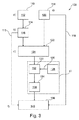
図1は、腫瘍を目標とするアブレーション計画のためのプランニング装置10を示している。装置10は、処理ユニット12、インターフェイスユニット14、および、ディスプレイユニット16を含んでいる。プランニング装置10は、模式的に周囲の枠18によって示されており、プランニング装置10の統合されたデザインを示している。もちろん、プランニング装置10の個々の部分は、また、分離したコンポーネントとしても提供され得る。
FIG. 1 shows a
インターフェイスユニット14は、3次元データセット20において少なくとも一つの区分化された腫瘍を提供するように構成されており、データセットは、アブレーション手順において取り扱われる。インターフェイスユニット14は、さらに、既定のアブレーションプロファイル22を提供するように構成されている。
The
処理ユニット12は、以下のように構成されている。区分化された腫瘍の輪郭24を生成し、少なくとも一つの区分化された腫瘍の少なくとも一つの部分を伴う既定のアブレーションプロファイルと重ね合わせ、重なり合った領域を特定し、変更された重なり合い領域を生成するために少なくとも重なり合い領域の一部について規定の安全ファクターを適用し、かつ、変更された重なり合い領域の外側に配置された重なり合い領域の部分を主要重なり合い部分26を決定する。
The
ディスプレイユニット16は、以下のように構成されている。区分化された輪郭24を表示し、少なくとも一つの区分化された腫瘍20の少なくとも一部と重なり合った既定のアブレーションプロファイル22を表示し、かつ、仮想計画アブレーション結果28として、輪郭20とアブレーションプロファイル22に関連して主要重なり合い部分26を表示する。
The
インターフェイスユニット14は、ユーザーによって既定のアブレーションプロファイル22が、その大きさ、形状、及び/又は、位置について調整されるように構成されてよい。処理ユニット12は、以下のことを繰り返すように構成されてよい。重なり合い領域を識別し、更新され変更された重なり合い領域を生成するための既定の安全ファクターを適用し、かつ、変更された重なり合い領域の外側に配置された重なり合い領域の部分を主要重なり合い部分として決定することである。
The
アブレーションプロファイルは、複数の(ほぼ並行な)アブレーション針によって操作される複数のプロファイルセットの連結を含んでよい。 The ablation profile may include a linkage of multiple profile sets operated by multiple (substantially parallel) ablation needles.
処理ユニット12は、腫瘍の拡張された輪郭を生成するために少なくとも一つの区分化された腫瘍に対して既定の第1の安全マージンを加えるように、かつ、アブレーションプロファイルの外側に配置された拡張された輪郭の部分を主要拡張輪郭部分として決定するように構成されてよい。ディスプレイユニット16は、拡張された輪郭を表示し、かつ、主要拡張輪郭部分を示すように構成されてよい。
The
処理ユニット12は、制限されたアブレーション計画プロファイルを生成するために既定のアブレーションプロファイルから既定の第2の安全マージンを引くように、かつ、アブレーション計画プロファイルの外側に配置された輪郭の部分を主要輪郭部分として決定するように構成されてよい。ディスプレイユニット16は、アブレーション計画プロファイルを表示し、かつ、主要輪郭部分を示すように構成されてよい。
The
図2は、腫瘍を目標とするアブレーションのための医療システム30を模式的に示している。医療システム300は、画像取得ユニット32を含んでおり、例えば、C型アーム構造体34は、C型アームの一端にX線光源36、C型アームの他端に検出器38を備えている。C型アーム構造体34は、天井40から吊り下げられており、対象物42に関して、光源と検出器を備えるC型アームを並行移動及び回転移動できる。対象物は、球体で示されているが、対象物は、また、患者(図示なし)でもあり得る。さらに、プランニング装置46と同様に、患者用テーブル44が示されている。これらは、上記に説明された典型的な実施例の一つに従って備えられる。さらに、アブレーションユニット48が模式的に示されている。
FIG. 2 schematically illustrates a
画像取得ユニット32は、区分化された腫瘍の3次元画像を提供するように構成されている。プランニング装置46は、アブレーションパスを提供するように構成されている。アブレーションユニット48は、腫瘍に対してアブレーション手順を適用するように構成されている。
The
画像取得ユニットは、例えばC型アーム構造体として示されるような、X線画像装置であり、また、ガントリー(gantry)を備えたCTシステム、または、他のX線画像システムであってもよい。画像取得ユニットは、また、MRI画像装置又は他の物であってもよい。 The image acquisition unit is an X-ray imaging device, for example as shown as a C-arm structure, and may be a CT system with a gantry or other X-ray imaging system. The image acquisition unit may also be an MRI imaging device or other object.
図3は、腫瘍を目標とするアブレーション計画のための方法100に係る基本的なステップを模式的に示している。供給ステップ110においては、少なくとも一つの区分化された腫瘍の3次元データセット112が提供され、区分化された腫瘍はアブレーション手順において取り扱われる。生成と表示のステップ114においては、区分化された腫瘍の輪郭が生成され表示される。表示することは第1の矢印115を用いて示されている(以下に説明される)。供給と表示のステップ118においては、少なくとも一つの区分化された腫瘍の少なくとも一部に重なり合うように、既定のアブレーションプロファイル120が提供され表示される。このステップの表示の態様は第2の矢印119を用いて示されている。次に、識別ステップ122においては、重なり合い領域124が特定される。適用ステップ126においては、既定の安全ファクターが重なり合い領域124の少なくとも一部に適用され、生成ステップ130において、変更された重なり合い領域132が生成される。変更された重なり合い領域の外側に配置された重なり合い領域の部分は、決定ステップ134において、主要重なり合い部分136として決定される。さらに、表示ステップ138においては、第1の矢印115を用いて示されるように、主要重なり合い部分136が輪郭116に関して表示され、第2の矢印119を用いて示されるように、アブレーションプロファイル120が、仮想計画アブレーション結果140として表示される。
FIG. 3 schematically illustrates the basic steps involved in the
供給ステップ110は、また、ステップa)としても参照され、生成と表示のステップ114はステップb)として、供給と表示のステップ118はステップc)として、識別ステップ122はステップd)として、適用ステップ126はステップe)として、そして、表示ステップ138はステップf)として参照される。
本方法は、また、腫瘍を目標とするアブレーション計画のための方法と類似のステップを有するデバイスを操作するための方法にも関連することに、さらに留意すべきである。 It should further be noted that the method also relates to a method for operating a device having similar steps as a method for ablation planning targeting a tumor.
アブレーションプロファイルは、アブレーション領域を表す等温線(isotherm)の断面図において示されてよい。 The ablation profile may be shown in a cross-sectional view of an isotherm representing the ablation region.
図4に示されるように、さらなる実施例に従って、既定のアブレーションプロファイル122は、大きさ、形状、及び/又は、位置においてユーザーによって調整可能である。このことは、図4において参照番号120’を用いて示されている。さらに、ステップd)からf)は、更新された情報を提供するために繰り返されてよい(さらには図示されない)。
As shown in FIG. 4, according to a further embodiment, the
図5は、さらなる実施例を示している。その中で、ステップe)は、生成ステップ150において拡張された輪郭を生成するために、安全ファクターとして既定の第1の安全マージン146を少なくとも一つの区分化された腫瘍に対して足し算144することを含んでいる。さらに、ステップe)は、また、参照番号149を用いて示されるように、拡張された輪郭148を表示することを含んでいる。次に、決定ステップ152において、アブレーションプロファイルの外側に配置されている拡張された輪郭148の部分が、主要拡張輪郭部分154として決定される。さらに、ステップf)において、主要拡張輪郭部分154は、指示ステップ156でディスプレイに表示される。
FIG. 5 shows a further embodiment. Among them, step e) adds 144 the
例えば、主要拡張輪郭部分は、カラーコード化されたプロファイルを用いて表示されてよい(図示なし)。 For example, the main extended contour portion may be displayed using a color coded profile (not shown).
図6は、本発明に従った、さらなる実施例を示している。その中で、ステップe)は、生成ステップ164において制限されたアブレーション計画プロファイル162を生成するために、既定の安全ファクターとしての既定の第2の安全マージン160を既定のアブレーションプロファイルから引き算158することを含んでいる。参照番号163を用いて示されるように、アブレーション計画プロファイルが表示される。さらに、決定ステップ166において、アブレーション計画プロファイルの外側に配置された輪郭の部分が主要輪郭部分168として決定される。ステップf)においては、主要輪郭部分が、指示ステップ170においてディスプレイに表示される。
FIG. 6 shows a further embodiment according to the present invention. Among them, step e) subtracts 158 the default
例えば、主要輪郭部分は、カラーコード化されたプロファイルを用いて表示されてよい(図示なし)。 For example, the main contour portion may be displayed using a color coded profile (not shown).
アブレーションプロファイルは、制限されたアブレーション計画プロファイルとは異なる方法でグラフィカルに表示されてよい。区分化された腫瘍は、アブレーション計画プロファイルが重なり合う区域/領域に対しては第1のモードで、アブレーション計画プロファイルが重なり合わない区域/領域に対しては第2のモードでグラフィカルに表示されてよい。 The ablation profile may be graphically displayed in a different manner than the limited ablation plan profile. The segmented tumor may be graphically displayed in a first mode for areas / regions where the ablation plan profiles overlap and in a second mode for areas / regions where the ablation plan profiles do not overlap. .
区分化された腫瘍は、周辺領域の画像データと重ね合わせて表示されてよい(さらには図示されない)。 The segmented tumor may be displayed superimposed on the image data of the surrounding area (and not shown).
画像データは、X線画像データであってよい。例えば、患者のCT画像データである。 The image data may be X-ray image data. For example, patient CT image data.
図7は、一つの実施例を示している。その中で、矢印174を用いて示されるように、腫瘍を目標とするアブレーションのためのアブレーション対象に係る挿入計画パス172が、仮想計画アブレーション結果140と供に表示される。
FIG. 7 shows one embodiment. The
主要拡張輪郭部分及び/又は主要輪郭部分の表示は、他のもの、つまり主要でない領域、とは異なるグラフィカルな方法で領域を表示することを含んでいる(さらには図示されない)。 The display of the main extended contour portion and / or the main contour portion includes displaying the region in a different graphical manner than the other, i.e., the non-main region (and not shown).
輪郭は、輪郭線であり、そして、拡張された輪郭は、拡張輪郭線である。 The contour is a contour line, and the expanded contour is an expanded contour line.
図8は、腫瘍断面輪郭を示している。図8Bはエントリーポイントにおけるもので、図8Aは進行ビューにおけるものである。両方の画像は、X線画像取得された背景画像210を示している。例えば、3次元データセットに係るCTベースのプロジェクションである。
FIG. 8 shows a tumor cross-sectional profile. FIG. 8B is at the entry point and FIG. 8A is at the progress view. Both images show a
図8A、8Bにおいては、区分化された患部の断面外形212が、2つの区別された線タイプで示されている。第1の線タイプ214と第2の線タイプ216を用いており、以下に詳しく説明される。さらに、アブレーション計画等温線218が示される。第1のパターン220は第1の等温線を示し、第2のパターン222は第2の等温線を示し、そして、第3のパターン224は第3の等温線を示している。
In FIGS. 8A and 8B, the sectioned
図8Aにおいて、第1の等温線220は、重なり合って配置された2つの円形領域を含んでいる。一方、図8Bでは、第1の等温線22は楕円形状で示されている。
In FIG. 8A, the
図8Bは、さらに、アブレーションを実行するためのインターベンション装置の挿入パス226を示している。例えば、アブレーション針である。
FIG. 8B further illustrates an intervention
プランニングの最中、針のパスとアブレーションプロファイルは、ユーザー定義の任意の視聴平面において指定され得る。目標とアプリケータのエントリーポイントを指定することによるものである。そして、保管された数多くのアブレーションプロファイルの中から最適のアブレーションプロファイルが選択される。同じワークフローを使用して、追加のアブレーションアプリケータが指定されてよい。目標ポイントだけを定めることによって、以前に選択されたアプリケータと並行してアプリケータを配置することも可能である。上述のように、アブレーション領域を表している等温線は、融合され混合された断面において、画像データの上に示される。このようにして、アブレーション領域と付随する針の軌道は、あらゆる平面の位置及び方法において検査され得る。 During planning, the needle path and ablation profile can be specified in any user-defined viewing plane. This is by specifying the target and applicator entry points. Then, the optimum ablation profile is selected from the stored ablation profiles. Additional ablation applicators may be designated using the same workflow. It is also possible to place the applicator in parallel with the previously selected applicator by defining only the target point. As described above, the isotherm representing the ablation region is shown above the image data in a fused and mixed section. In this way, the ablation area and associated needle trajectory can be examined in any plane position and manner.
腫瘍カバーフィードバックは、破壊的なアブレーションプロファイルをステンシルバッファー(stencil buffer)の中に最初にレンダリング(rendering)することによって、オープンGLにおいて実施され得る。ステンシルテストを使用することにより、ステンシルバッファー領域が重なることなく、異なる色で断面外形を2回レンダリングすることができる。このことは、以下のコードスニペットによって典型的に行われる。
glEnable(GL_STENCIL_TEST);
SetContourColor(Vector3D(0.4, 1.0, 0.4));
glStencilOp(GL_KEEP, GL_KEEP, GL_KEEP);
glStencilFunc(GL_NOTEQUAL, 0, CmodelAblation::STENCILMASK_ALL);
DrawContours();
glStencilFunc(GL_EQUAL, 0, CmodelAblation::STENCILMASK_ALL);
SetContourColor(Vector3D(1.0, 0.4, 0.4));
DrawContours();
glDisable(GL_STENCIL_TEST);
Tumor cover feedback can be performed in open GL by first rendering a destructive ablation profile into a stencil buffer. By using the stencil test, the cross-sectional outline can be rendered twice with different colors without overlapping stencil buffer areas. This is typically done by the following code snippet.
glEnable (GL_STENCIL_TEST);
SetContourColor (Vector3D (0.4, 1.0, 0.4));
glStencilOp (GL_KEEP, GL_KEEP, GL_KEEP);
glStencilFunc (GL_NOTEQUAL, 0, CmodelAblation :: STENCILMASK_ALL);
DrawContours ();
glStencilFunc (GL_EQUAL, 0, CmodelAblation :: STENCILMASK_ALL);
SetContourColor (Vector3D (1.0, 0.4, 0.4));
DrawContours ();
glDisable (GL_STENCIL_TEST);
腫瘍を完全にカバーするためには追加の針が必要となることがある。画像断面を通じて眺めることにより、種々の平面の位置及び方向において重なり合いが検査され得る。図9におけるマルチビュー表示の左上に示されるように、ボリュームレンダリングモードにおいて、アブレーション計画ボリュームが、区分化された腫瘍ボリュームと相対的に表示され得る。4分割の左上は、第1の色230でアブレーションボリュームの所定の等温線を示している。等温線は、第2の色232で示される腫瘍ボリュームの上に重ねて透過的に混合されている。
Additional needles may be required to completely cover the tumor. By looking through the image cross section, the overlap can be examined at various plane positions and orientations. As shown in the upper left of the multi-view display in FIG. 9, in the volume rendering mode, the ablation planned volume can be displayed relative to the segmented tumor volume. The upper left of the four divisions shows a predetermined isotherm of the ablation volume with the
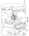
上述のように、アブレーションの成功のためには腫瘍全体を完全に壊死させることが必要である。患部の周辺マージンについても同様であり、例えば、05から1cmのマージンである。マージンは区分化された腫瘍の記述に追加されてよく、結果として生じるボリュームは、計画対象ボリューム(PTV)として参照される。追加されたマージンは、腫瘍境界の実際の位置を隠し/無効にする。これは、血管(ヒートシンク)の近傍において重要であり、安全マージンが緩和される必要があり得るところである。本発明に従って、2つの外形が示されている。実際の区分化された腫瘍に対する第1の輪郭234、および、計画対象ボリュームに対する第2の輪郭236である(図10)。区分化された患部の境界、つまり第1の線234、は第1の色で示されてよい。ユーザーがコントロール可能で透明な第1のパターン238であり、例えば、透明な赤色の楕円であって、重なり合ったアブレーションプロファイルと供に平面断面図を示している(さらには図示されない)。
As mentioned above, the entire tumor needs to be completely necrotic for successful ablation. The same applies to the margin around the affected area, for example, a margin of 05 to 1 cm. Margins may be added to the segmented tumor description, and the resulting volume is referred to as the planned volume (PTV). The added margin hides / invalidates the actual location of the tumor boundary. This is important in the vicinity of the blood vessel (heat sink) and is where the safety margin may need to be relaxed. In accordance with the present invention, two outlines are shown. A
図10においては、初期アブレーションプロファイルが腫瘍をカバーする。本発明に従って、腫瘍外形に安全ファクターを適用することによって、より大きな腫瘍外形が結果として得られる。このより大きな外形は、アブレーションプロファイルによって完全にはカバーされない。従って、より大きな腫瘍外形に変更することがそれぞれ指示される。 In FIG. 10, the initial ablation profile covers the tumor. In accordance with the present invention, applying a safety factor to the tumor profile results in a larger tumor profile. This larger profile is not completely covered by the ablation profile. Therefore, each is instructed to change to a larger tumor profile.
拡張された輪郭に伴う適用範囲の重なり合いを表示することに加えて、「実際の」腫瘍輪郭、つまり、安全ファクターを適用する以前の輪郭、に伴う重なり合いを決定、つまり計算して表示することも可能である。 In addition to displaying coverage overlap with extended contours, it is also possible to determine, calculate and display the overlap with “real” tumor contours, ie prior to applying safety factors. Is possible.
図11は、(おそらくカラーコード化された)安全マージンが等温線の仕様に含まれている場合に従った、代替的なアプローチを示している。重なり合いとカラーコード化により、第1のコントラ線(contra−line)334の内側に配置され、第1のパターン336を用いて示される内側アブレーションプロファイルと、第2のパターン338を用いて示される外側アブレーションプロファイルを伴う区分化された患部は、安全マージンを提供する。冷凍アブレーションの場合には、アプリケータ製造者によって提供されるように、外側のゼロ度等温線が自然な安全マージンを提供する。
FIG. 11 shows an alternative approach according to the case where a safety margin (possibly color coded) is included in the isotherm specification. Due to the overlap and color coding, the inner ablation profile placed inside the first contra-
図11では、再度、初期アブレーションプロファイルが腫瘍をカバーしている。安全ファクターをアブレーションプロファイルに対して適用することによって、本発明に従えば、より小さなアブレーションプロファイルを結果として生じる。このより小さいプロファイルは、ここでは、腫瘍を完全にはカバーしない。よって、腫瘍外形の変更がそれぞれ示される。 In FIG. 11 again, the initial ablation profile covers the tumor. By applying a safety factor to the ablation profile, in accordance with the present invention, a smaller ablation profile results. This smaller profile here does not completely cover the tumor. Thus, each change in tumor profile is indicated.
図9に示されるように、第1(ゼロ度)の等温線が、カラーコード化された腫瘍境界表現におけるマスク(mask)として使用される。 As shown in FIG. 9, the first (zero degree) isotherm is used as a mask in the color coded tumor boundary representation.
ラジオ周波数アブレーション又はマイクロ波アブレーションを使用して、楕円形のアブレーション領域を特定することができる。安全マージンを定めることによって、第2のより小さな同心円のアブレーションプロファイルが自動的に構成される。以降の所見により図12に示されるようにである。 Radio frequency ablation or microwave ablation can be used to identify an elliptical ablation region. By defining a safety margin, a second smaller concentric ablation profile is automatically constructed. It is as shown in FIG. 12 by subsequent observations.
楕円(L、W)アブレーションプロファイルの原点(O)は、アプリケータ針の先端(T)に関して、関係式:O=T+F−L/2によって定義される。ここで、Fは、針の先端から延びるアブレーション領域の前部(Front)である。より小さい楕円(L−M、WーM)は、関係式:O=T+F2−(LーM)/2によって定義される。ここで、Mは安全マージンである。楕円形は、以下の式を使用してアイソセンタ(iso−centric)形状にすることができる。
T+F−L/2=T+F2−(LーM)/2 −> F2=M/2
The origin (O) of the ellipse (L, W) ablation profile is defined by the relational expression: O = T + F−L / 2 with respect to the tip (T) of the applicator needle. Here, F is a front part (Front) of the ablation region extending from the tip of the needle. Smaller ellipse (L-M, W over M) is relation: O = T + F 2 - is defined by (L over M) / 2. Here, M is a safety margin. The ellipse can be made into an iso-centric shape using the following equation:
T + F−L / 2 = T + F 2 − (LM) / 2 −> F 2 = M / 2
例えば、20mmの距離において10分間45Wで活性化された3つのMWA valley Lab VT1237経皮アンテナを使用して作成されたアブレーション領域の大きさの見積りは、L=55mm、W=50mm、F=10mmである楕円形の定義によって定められる。よって、この場合に、10mmの安全領域を伴う内側の楕円形は、L=45mm、W=40mm、F=5mmとなる。 For example, estimates of the size of the ablation area created using three MWA valley Lab VT1237 transcutaneous antennas activated at 45 W for 10 minutes at a distance of 20 mm are L = 55 mm, W = 50 mm, F = 10 mm. Is defined by the definition of an oval. Therefore, in this case, the inner ellipse with a safety area of 10 mm is L = 45 mm, W = 40 mm, and F = 5 mm.
図11の画像は、このアブレーションプロファイルの使用を示している。内側の輪郭は、区分化された患部領域の断面を表している。外側の輪郭は、拡張されたPTVに伴う断面を表示している。図11を図10と比較すると、ハイライトされた輪郭によって示されるように、実際の腫瘍境界が内側アブレーション領域の外側にある場合には、第1のパターンで表示される拡張された腫瘍の断面が、実際に予測されたアブレーションの外側にあることに留意すべきである。よって、拡張された患部を予測されたアブレーション領域と重ね合わせる代わりに、今や実際の患部を変更されたアブレーションプロファイルに重ね合わせるときである。拡張された患部の境界は、もはや何の臨床的価値も持たないので、除外することができる。このことは、例えば、図13のマルチビュー表示において示されている。 The image in FIG. 11 illustrates the use of this ablation profile. The inner contour represents a section of the affected area that has been segmented. The outer contour displays a cross section with the expanded PTV. Comparing FIG. 11 with FIG. 10, an expanded tumor cross-section displayed in a first pattern when the actual tumor boundary is outside the inner ablation region, as shown by the highlighted contour. It should be noted that this is outside the actual predicted ablation. Thus, instead of overlaying the expanded affected area with the predicted ablation region, it is now time to overlay the actual affected area with the modified ablation profile. The expanded affected border no longer has any clinical value and can be excluded. This is shown, for example, in the multi-view display of FIG.
より良い理解のために、図8から図11、および、図13が、写真の画像と供に図14から図18にも示されている。 For better understanding, FIGS. 8-11 and 13 are also shown in FIGS. 14-18 with photographic images.
本発明の別の典型的な実施例において、コンピュータープログラム又はコンピュータープログラムエレメントが提供される。これらは、好適なシステム上で、上述の実施例の一つに従った方法のステップを実行するように適用されていることで特徴付けられる。 In another exemplary embodiment of the present invention, a computer program or computer program element is provided. These are characterized in that they are adapted to carry out the steps of the method according to one of the embodiments described above on a suitable system.
コンピュータープログラムエレメントは、従って、コンピューターユニット上に保管することができ、本発明の実施例に係る部分でもあり得る。このコンピューターユニットは、上述の方法のステップを実行、または、引き出すように適合されてよい。さらには、上述の装置に係るコンポーネントを操作するように適合されてよい。コンピューターユニットは、自動的に動作するように、及び/又は、ユーザー命令を実行するように適合されてよい。コンピュータープログラムは、データプロセッサの作業メモリーの中にロードされる。データプロセッサは、このように、本発明に係る方法を実行するために備えられている。 The computer program element can therefore be stored on the computer unit and can also be part of an embodiment of the present invention. The computer unit may be adapted to perform or derive the method steps described above. Furthermore, it may be adapted to operate a component according to the above-described apparatus. The computer unit may be adapted to operate automatically and / or to execute user instructions. The computer program is loaded into the working memory of the data processor. A data processor is thus provided for carrying out the method according to the invention.
本発明に係るこの典型的な実施例は、当初から本発明を使用するコンピュータープログラムと、アップデートによって既存のプログラムを本発明を使用するプログラムに変更するコンピュータープログラムの両方をカバーするものである。 This exemplary embodiment of the present invention covers both a computer program that uses the present invention from the beginning and a computer program that changes an existing program to a program that uses the present invention by updating.
さらに、コンピュータープログラムエレメントは、上述のように、典型的な方法の実施例の手順を満足するために必要な全てのステップを提供することができる。 Furthermore, the computer program element can provide all the steps necessary to satisfy the procedure of the exemplary method embodiment, as described above.
本発明のさらなる実施例に従えば、CD−ROMといった、コンピューターで読取り可能な媒体が示される。コンピューターで読取り可能な媒体は、媒体上にコンピュータープログラムエレメントを保管しており、コンピュータープログラムエレメントは前出の章で説明されたものである。 According to a further embodiment of the invention, a computer readable medium such as a CD-ROM is shown. The computer readable medium stores computer program elements on the medium, and the computer program elements are those described in the previous chapter.
コンピュータープログラムは、他のハードウェアと供に、もしくは、ハードウェアの一部として供給される光記録媒体、または、半導体媒体といった、好適な媒体上に保管され、及び/又は、流通される。しかし、コンピュータープログラムは、また、インテーネット、または、他の有線又は無線の電気通信システムを介してといった、他の形式において流通されてもよい。 The computer program is stored and / or distributed on a suitable medium such as an optical recording medium or a semiconductor medium supplied with other hardware or as a part of the hardware. However, the computer program may also be distributed in other forms, such as via the Internet or other wired or wireless telecommunication systems.
しかしながら、コンピュータープログラムは、ワールドワイドウェブ(World Wide Web)のようなネットワークにわたり存在することもでき、そうしたネットワークからデータプロセッサの作業メモリーの中にダウンロードすることもできる。本発明のさらなる典型的な実施例に従えば、ダウンロードのために利用可能なコンピュータープログラムエレメントを作成するための媒体が提供される。コンピュータープログラムエレメントは、本発明に係る以前に説明した実施例の一つに従った方法を実行するように構成されている。 However, the computer program can also exist over a network such as the World Wide Web and can be downloaded from such a network into the working memory of the data processor. In accordance with a further exemplary embodiment of the present invention, a medium is provided for creating a computer program element that is available for download. The computer program element is configured to perform a method according to one of the previously described embodiments according to the present invention.
本発明の実施例は、異なる技術的事項に関して説明されていることに留意しなければならない。特に、いくつかの実施例は、方法タイプの請求項に関して説明されているが、一方で、他の実施例は、装置タイプの請求項に関して説明されている。しかしながら、当業者であれば、上記及び以降の説明から、そうでないものと記載されていなければ、一つのタイプの技術的事項に属する特徴のあらゆる組み合わせに加えて、異なる技術的事項に関する特徴間でのあらゆる組み合わせもまた、本特許出願と供に開示されていると考えられることが理解されよう。しかしながら、全ての特徴は、特徴の単なる足し算以上であるシナジー効果を提供するように組み合わされ得るものである。 It has to be noted that the embodiments of the invention have been described with respect to different technical matters. In particular, some embodiments are described with respect to method type claims, while other embodiments are described with respect to device type claims. However, those skilled in the art, from the above and following descriptions, between features relating to different technical matters, in addition to any combination of features belonging to one type of technical matter, unless otherwise stated. It will be understood that any combination of is considered to be disclosed with this patent application. However, all the features can be combined to provide a synergistic effect that is more than just adding the features.
本発明は、図面または前出の記載において、その詳細が説明され記述されてきたが、そうした説明および記載は、説明的または例示的なものであり、制限的なものではないと考えられるべきである。本発明は、開示された実施例に限定されるものではない。図面、明細書、および添付の特許請求の範囲を研究すれば、請求された本発明の実施において、当業者によって、開示された実施例に対する他の変形が理解され、もたらされ得る。 While the invention has been illustrated and described in detail in the drawings or foregoing description, such description and description are to be considered illustrative or exemplary and not restrictive. is there. The invention is not limited to the disclosed embodiments. Upon studying the drawings, specification, and appended claims, other variations to the disclosed embodiments can be understood and effected by those skilled in the art in practicing the claimed invention.
請求項において、用語「含む(“comprising“」は、他のエレメントまたはステップの存在を排除するものではなく、不定冠詞「一つの(”a“または”an“)」は、複数を排除するものではない。単一のプロセッサまたは他のユニットは、請求項で述べられる数個のアイテムに係る機能を満たし得る。特定の手段が、お互いに異なる従属請求項の中で引用されているという事実だけでは、これらの手段の組合せが有利に使用され得ないことを示すものではない。請求項におけるいかなる参照番号も、発明の範囲を限定するものと解釈されるべきではない。 In the claims, the term “comprising” does not exclude the presence of other elements or steps, and the indefinite article “a” or “an” is intended to exclude a plurality. A single processor or other unit may fulfill the functions of several items stated in the claims, only the fact that specific means are cited in different dependent claims. Does not indicate that a combination of these means cannot be used to advantage, and any reference signs in the claims should not be construed as limiting the scope.
Claims (15)
処理ユニットと;
インターフェイスユニットと;
ディスプレイユニットと、を含み、
前記インターフェイスユニットは、
アブレーション手順で扱われるべき3次元データセットにおける少なくとも一つの区分化された腫瘍を提供し、かつ、
既定のアブレーションプロファイルを提供する、
ように構成されており、
前記処理ユニットは、
前記区分化された腫瘍の輪郭を生成し、
前記既定のアブレーションプロファイルを前記少なくとも一つの区分化された腫瘍の少なくとも一部と重ね合わせ、
重なり合い領域を特定し、
変更された重なり合い領域を生成するために少なくとも前記重なり合い領域の一部について規定の安全ファクターを適用し、かつ、
前記変更された重なり合い領域の外側に配置された前記重なり合い領域の部分を主要重なり合い部分として決定する、
ように構成されており、
前記ディスプレイユニットは、
前記区分化された輪郭を表示し、
少なくとも一つの前記区分化された腫瘍の少なくとも一部と重なり合った前記既定のアブレーションプロファイルを表示し、かつ、
仮想計画アブレーション結果として、前記輪郭と前記アブレーションプロファイルに関連して前記主要重なり合い部分を表示する、
ように構成されている、
ことを特徴とする装置。 A planning device for ablation planning targeting tumors:
With a processing unit;
With an interface unit;
A display unit, and
The interface unit is
Providing at least one segmented tumor in a three-dimensional data set to be treated in an ablation procedure; and
Provide a default ablation profile,
Is configured as
The processing unit is
Generating a contour of the segmented tumor;
The default ablation profile superimposed with at least a portion of the at least one segmented tumor,
To identify the overlap agreement area,
Applying a safety factor defined for at least a portion of the overlap region to produce a that modified overlapping area, and,
Determining the portion of the overlapping region is disposed outside of said modified overlapping area as a major overlap portion,
Is configured as
The display unit is
Displaying the segmented contour;
Displaying the predetermined ablation profile overlapping at least a portion of at least one of the segmented tumors; and
Displaying the main overlap as a virtual plan ablation result in relation to the contour and the ablation profile;
Configured as
A device characterized by that.
前記処理ユニットは、
重なり合い領域を識別し、更新され変更された重なり合い領域を生成するための既定の安全ファクターを適用し、かつ、変更された重なり合い領域の外側に配置された重なり合い領域の部分を主要重なり合い部分として決定すること、
を繰り返すように構成されており、
前記ディスプレイユニットは、更新されたアブレーション計画情報を提供するように構成されている、
請求項1に記載の装置。 The interface unit is configured such that a predetermined ablation profile is adjusted by the user for its size, shape, and / or position;
The processing unit is
Identify areas overlap, and are updated by applying the default safety factor for generating the modified overlapping area, and to determine as the main overlapping portion the modified overlapping portions of the arranged overlap region outside the region about,
Is configured to repeat,
The display unit is configured to provide updated ablation plan information;
The apparatus of claim 1.
前記腫瘍の拡張された輪郭を生成するために、前記少なくとも一つの区分化された腫瘍に対して既定の第1の安全マージンを加えるように、かつ、
前記アブレーションプロファイルの外側に配置された前記拡張された輪郭の部分を主要拡張輪郭部分として決定する、
ように構成されており、
前記ディスプレイユニットは、前記拡張された輪郭を表示し、かつ、前記主要拡張輪郭部分を示すように構成されている、
請求項1または2に記載の装置。 The processing unit is
Adding a predetermined first safety margin to the at least one segmented tumor to generate an expanded contour of the tumor; and
Determining a portion of the expanded contour located outside the ablation profile as a main expanded contour portion;
Is configured as
The display unit is configured to display the expanded contour and to indicate the main expanded contour portion;
The apparatus according to claim 1 or 2.
制限されたアブレーション計画プロファイルを生成するために、前記既定のアブレーションプロファイルから既定の第2の安全マージンを引くように、かつ、
前記アブレーション計画プロファイルの外側に配置された輪郭の部分を主要輪郭部分として決定する、
ように構成されており、
前記ディスプレイユニットは、前記アブレーション計画プロファイルを表示し、かつ、前記主要輪郭部分を示すように構成されている、
請求項1乃至3のいずれか一項に記載の装置。 The processing unit is
Subtracting a predetermined second safety margin from the default ablation profile to generate a limited ablation plan profile; and
Determining a contour portion arranged outside the ablation plan profile as a main contour portion;
Is configured as
The display unit is configured to display the ablation plan profile and to show the main contour portion;
The apparatus according to claim 1.
画像取得ユニットと;
請求項1乃至4のいずれか一項に従ったプランニング装置と;
アブレーションユニットと;を含み、
前記画像取得ユニットは、前記3次元データセットを提供するように構成されており、前記腫瘍はそこから区分化され;
前記プランニング装置は、アブレーションパスを提供するように構成されており;かつ、
前記アブレーションユニットは、前記アブレーション手順を前記腫瘍に対して適用するように構成されている、
ことを特徴とする医療システム。 A medical system for ablation targeting tumors:
An image acquisition unit;
A planning device according to any one of claims 1 to 4;
An ablation unit; and
The image acquisition unit is configured to provide the three-dimensional data set, and the tumor is segmented therefrom;
The planning device is configured to provide an ablation path; and
The ablation unit is configured to apply the ablation procedure to the tumor;
A medical system characterized by that.
請求項5に記載の医療システム。 The image acquisition unit is an X-ray imaging device;
The medical system according to claim 5.
a)前記プランニング装置のインターフェイスユニットが、アブレーション手順で扱われるべき3次元データセットにおける少なくとも一つの区分化された腫瘍を提供するステップと;
b)前記プランニング装置の処理ユニットが、前記区分化された腫瘍の輪郭を生成及び表示するステップと;
c)前記プランニング装置の処理ユニットが、既定のアブレーションプロファイルを少なくとも一つの区分化された腫瘍の少なくとも一部と重ね合わせるように提供及び表示するステップと;
d)前記プランニング装置の処理ユニットが、重なり合い領域を特定するステップと;
e)前記プランニング装置の処理ユニットが、変更された重なり合い領域を生成するために少なくとも前記重なり合い領域の一部について規定の安全ファクターを適用するステップであり、前記変更された重なり合い領域の外側に配置された前記重なり合い領域の部分が主要重なり合い部分として決定されるステップと;
f)前記プランニング装置のディスプレイユニットが、仮想計画アブレーション結果として、前記輪郭と前記アブレーションプロファイルに関連して前記主要重なり合い部分を表示するステップと、
を含む、ことを特徴とする方法。 A method for ablation planning targeting a tumor using a planning device comprising :
a) the interface unit of the planning device providing at least one segmented tumor in a three-dimensional data set to be treated in an ablation procedure;
b) the processing unit of the planning device generating and displaying the segmented tumor profile;
c) providing and displaying a predetermined ablation profile overlaid with at least a portion of the at least one segmented tumor by the processing unit of the planning device ;
d) processing units of the planning device, identifying the overlapping agreed region;
e) processing units of the planning device is a step of applying a safety factor defined for at least a portion of the overlap region to produce a that modified overlapping area, are disposed outside the modified overlapping area a step portion of the overlapping area is determined as the main overlapping portion was;
f) the display unit of the planning device displaying the main overlap as a virtual plan ablation result in relation to the contour and the ablation profile;
A method characterized by comprising:
更新された情報を提供するために、前記d)からf)までのステップが繰り返される、
請求項7に記載の方法。 The default ablation profile can be adjusted by the user for its size, shape, and / or position;
Steps d) to f) are repeated to provide updated information.
The method of claim 7.
前記腫瘍の拡張された輪郭を生成するために、前記少なくとも一つの区分化された腫瘍に対して既定の第1の安全マージンを加える段階と;
前記拡張された輪郭を表示する段階と;
前記アブレーションプロファイルの外側に配置された前記拡張された輪郭の部分を主要拡張輪郭部分として決定する段階と、
を含み、
前記ステップf)において、前記主要拡張輪郭部分がディスプレイユニットに表示される、
請求項7または8に記載の方法。 Said step e)
Adding a predetermined first safety margin to the at least one segmented tumor to generate an expanded contour of the tumor;
Displaying the expanded contour;
Determining a portion of the expanded contour located outside the ablation profile as a main expanded contour portion;
Including
In step f), the main extended contour portion is displayed on a display unit;
The method according to claim 7 or 8.
制限されたアブレーション計画プロファイルを生成するために、前記既定のアブレーションプロファイルから既定の第2の安全マージンを引く段階と;
アブレーション計画プロファイルを表示する段階と;
前記アブレーション計画プロファイルの外側に配置された輪郭の部分を主要輪郭部分として決定する段階と、
を含み、
前記ステップf)において、前記主要輪郭部分がディスプレイユニットに表示される、
請求項7乃至9のいずれか一項に記載の方法。 Said step e)
Subtracting a predefined second safety margin from the predefined ablation profile to generate a limited ablation plan profile;
Displaying the ablation plan profile;
Determining a contour portion located outside the ablation plan profile as a main contour portion;
Including
In step f), the main contour portion is displayed on a display unit;
10. A method according to any one of claims 7-9.
請求項7乃至10のいずれか一項に記載の方法。 The segmented tumor is displayed superimposed on the image data of the surrounding area.
11. A method according to any one of claims 7 to 10.
請求項7乃至11のいずれか一項に記載の方法。 An insertion planning path for the ablation subject for ablation targeting the tumor is shown.
12. A method according to any one of claims 7 to 11.
請求項9乃至12のいずれか一項に記載の方法。 The display of the main extended contour portion and / or the main contour portion displays the region in a graphic manner different from each other region,
A method according to any one of claims 9 to 12.
処理ユニットによって実行されると、
請求項7乃至13のいずれか一項に記載の方法を実行するように適合されている、
ことを特徴とするコンピュータープログラム。 A computer program for controlling the device according to any one of claims 1 to 6,
When executed by the processing unit,
Adapted to carry out the method according to any one of claims 7 to 13,
A computer program characterized by that.
Applications Claiming Priority (3)
| Application Number | Priority Date | Filing Date | Title |
|---|---|---|---|
| US201161533815P | 2011-09-13 | 2011-09-13 | |
| US61/533,815 | 2011-09-13 | ||
| PCT/IB2012/054687 WO2013038324A1 (en) | 2011-09-13 | 2012-09-10 | Ablation planning with lesion coverage feedback |
Publications (2)
| Publication Number | Publication Date |
|---|---|
| JP2014534831A JP2014534831A (en) | 2014-12-25 |
| JP5933723B2 true JP5933723B2 (en) | 2016-06-15 |
Family
ID=47143974
Family Applications (1)
| Application Number | Title | Priority Date | Filing Date |
|---|---|---|---|
| JP2014530353A Active JP5933723B2 (en) | 2011-09-13 | 2012-09-10 | Ablation planning using affected area feedback |
Country Status (5)
| Country | Link |
|---|---|
| US (1) | US9839482B2 (en) |
| EP (1) | EP2744438B1 (en) |
| JP (1) | JP5933723B2 (en) |
| CN (1) | CN103796607B (en) |
| WO (1) | WO2013038324A1 (en) |
Families Citing this family (24)
| Publication number | Priority date | Publication date | Assignee | Title |
|---|---|---|---|---|
| US11264139B2 (en) * | 2007-11-21 | 2022-03-01 | Edda Technology, Inc. | Method and system for adjusting interactive 3D treatment zone for percutaneous treatment |
| WO2014093367A1 (en) * | 2012-12-10 | 2014-06-19 | Intuitive Surgical Operations, Inc. | Collision avoidance during controlled movement of image capturing device and manipulatable device movable arms |
| CA2914195C (en) | 2013-06-03 | 2020-06-02 | Nanoblate Corporation | Methods and devices for stimulating an immune response using nanosecond pulsed electric fields |
| US10925511B2 (en) | 2014-07-24 | 2021-02-23 | Cardiosolv Ablation Technologies, Inc. | System and method for cardiac ablation |
| US11227427B2 (en) | 2014-08-11 | 2022-01-18 | Covidien Lp | Treatment procedure planning system and method |
| AU2015355241B2 (en) | 2014-12-01 | 2019-10-24 | Pulse Biosciences, Inc. | Nanoelectroablation control and vaccination |
| US10607738B2 (en) | 2015-05-15 | 2020-03-31 | University Health Network | System and method for minimally invasive thermal ablation treatment planning |
| US10548665B2 (en) | 2016-02-29 | 2020-02-04 | Pulse Biosciences, Inc. | High-voltage analog circuit pulser with feedback control |
| US10874451B2 (en) | 2016-02-29 | 2020-12-29 | Pulse Biosciences, Inc. | High-voltage analog circuit pulser and pulse generator discharge circuit |
| EP3457976A4 (en) | 2016-05-16 | 2019-12-11 | Pulse Biosciences, Inc. | Pulse applicator |
| US10543357B2 (en) | 2016-09-19 | 2020-01-28 | Pulse Biosciences, Inc. | High voltage connectors for pulse generators |
| CN108245244B (en) * | 2016-12-28 | 2019-12-13 | 中国科学院深圳先进技术研究院 | Radio frequency ablation method and device |
| US10946193B2 (en) | 2017-02-28 | 2021-03-16 | Pulse Biosciences, Inc. | Pulse generator with independent panel triggering |
| WO2019010232A1 (en) * | 2017-07-07 | 2019-01-10 | Canon U.S.A. Inc. | Multiple probe ablation planning |
| US10857347B2 (en) | 2017-09-19 | 2020-12-08 | Pulse Biosciences, Inc. | Treatment instrument and high-voltage connectors for robotic surgical system |
| US11197723B2 (en) | 2017-10-09 | 2021-12-14 | Canon U.S.A., Inc. | Medical guidance system and method using localized insertion plane |
| US10918441B2 (en) | 2017-11-22 | 2021-02-16 | Canon U.S.A., Inc. | Devices, systems, and methods for ablation-zone simulation and visualization |
| US10751128B2 (en) | 2017-11-22 | 2020-08-25 | Canon U.S.A., Inc. | Devices, systems, and methods for ablation-zone simulation and visualization |
| EP3749239A4 (en) * | 2018-02-05 | 2021-11-03 | Broncus Medical Inc. | Image-guided lung tumor planning and ablation system |
| CN109077801B (en) * | 2018-06-27 | 2020-06-12 | 清华大学 | Diagnosis and treatment method and system for multi-source information guided laser ablation |
| US11571569B2 (en) | 2019-02-15 | 2023-02-07 | Pulse Biosciences, Inc. | High-voltage catheters for sub-microsecond pulsing |
| CN112315579B (en) * | 2020-11-25 | 2021-07-02 | 上海睿刀医疗科技有限公司 | Electrode needle distribution device and method based on focus area |
| CN113838556A (en) * | 2021-09-24 | 2021-12-24 | 北京三春晖医疗器械有限公司 | Composite pulse electric field tumor ablation planning system |
| CN113952030B (en) * | 2021-10-28 | 2023-12-15 | 北京深睿博联科技有限责任公司 | Planning method and device for needle insertion path and ablation position of radio frequency electrode |
Family Cites Families (12)
| Publication number | Priority date | Publication date | Assignee | Title |
|---|---|---|---|---|
| US6575969B1 (en) | 1995-05-04 | 2003-06-10 | Sherwood Services Ag | Cool-tip radiofrequency thermosurgery electrode system for tumor ablation |
| US7343030B2 (en) | 2003-08-05 | 2008-03-11 | Imquant, Inc. | Dynamic tumor treatment system |
| CN1686052A (en) * | 2004-12-23 | 2005-10-26 | 中国科学院等离子体物理研究所 | Method of non contact measuring breast belly tumour position for radiation treatment |
| US20070129626A1 (en) * | 2005-11-23 | 2007-06-07 | Prakash Mahesh | Methods and systems for facilitating surgical procedures |
| US7871406B2 (en) | 2006-08-04 | 2011-01-18 | INTIO, Inc. | Methods for planning and performing thermal ablation |
| US8663083B2 (en) * | 2006-12-08 | 2014-03-04 | Koninklijke Philips N.V. | System, method, computer-readable medium, and use for planning combined therapy |
| US9747684B2 (en) | 2007-01-24 | 2017-08-29 | Koninklijke Philips N.V. | RF ablation planner |
| US8267927B2 (en) | 2007-01-24 | 2012-09-18 | Koninklijke Philips Electronics N.V. | Advanced ablation planning |
| WO2009067654A1 (en) | 2007-11-21 | 2009-05-28 | Edda Technology, Inc. | Method and system for interactive percutaneous pre-operation surgical planning |
| AT506293B1 (en) | 2008-07-16 | 2009-08-15 | Univ Innsbruck | METHOD OF ILLUSTRATING AN OBJECT AND DEVICE FOR CARRYING OUT THE METHOD |
| US9125689B2 (en) * | 2009-12-08 | 2015-09-08 | Koninklijke Philips N.V. | Clipping-plane-based ablation treatment planning |
| US20120277763A1 (en) | 2009-12-30 | 2012-11-01 | Koninklijke Philips Electronics N.V. | Dynamic ablation device |
-
2012
- 2012-09-10 US US14/342,444 patent/US9839482B2/en active Active
- 2012-09-10 JP JP2014530353A patent/JP5933723B2/en active Active
- 2012-09-10 WO PCT/IB2012/054687 patent/WO2013038324A1/en active Application Filing
- 2012-09-10 CN CN201280044278.8A patent/CN103796607B/en active Active
- 2012-09-10 EP EP12783294.7A patent/EP2744438B1/en active Active
Also Published As
| Publication number | Publication date |
|---|---|
| JP2014534831A (en) | 2014-12-25 |
| EP2744438B1 (en) | 2015-04-22 |
| CN103796607A (en) | 2014-05-14 |
| US20140228835A1 (en) | 2014-08-14 |
| CN103796607B (en) | 2017-01-18 |
| US9839482B2 (en) | 2017-12-12 |
| WO2013038324A1 (en) | 2013-03-21 |
| EP2744438A1 (en) | 2014-06-25 |
Similar Documents
| Publication | Publication Date | Title |
|---|---|---|
| JP5933723B2 (en) | Ablation planning using affected area feedback | |
| EP2640292B1 (en) | System for probabilistic ablation planning | |
| US20210007805A1 (en) | Ablation planning system | |
| US11026750B2 (en) | Real-time surgical navigation | |
| JP7289340B2 (en) | Planning for multiple probe ablation | |
| CN106691580B (en) | System and method for ultrasound image guided ablation antenna placement | |
| EP2124795B1 (en) | Rf ablation planner | |
| US20120277763A1 (en) | Dynamic ablation device | |
| US20170100195A1 (en) | Systems and methods for planning image-guided interventional procedures | |
| US20110251607A1 (en) | Feedback system for integrating interventional planning and navigation | |
| US9147289B2 (en) | Method for visualizing the quality of an ablation process | |
| JP2007144180A (en) | Method and system for facilitating surgical procedures | |
| EP3515310B1 (en) | Volume presentation for planning a location of an injection point | |
| CN114302687A (en) | Determining ablation probe configuration | |
| JP2023521839A (en) | Ablation treatment system | |
| JP7421488B2 (en) | Automatic ablation antenna segmentation from CT images |
Legal Events
| Date | Code | Title | Description |
|---|---|---|---|
| A621 | Written request for application examination |
Free format text: JAPANESE INTERMEDIATE CODE: A621 Effective date: 20150907 |
|
| A871 | Explanation of circumstances concerning accelerated examination |
Free format text: JAPANESE INTERMEDIATE CODE: A871 Effective date: 20151029 |
|
| A975 | Report on accelerated examination |
Free format text: JAPANESE INTERMEDIATE CODE: A971005 Effective date: 20151124 |
|
| A131 | Notification of reasons for refusal |
Free format text: JAPANESE INTERMEDIATE CODE: A131 Effective date: 20151201 |
|
| A521 | Request for written amendment filed |
Free format text: JAPANESE INTERMEDIATE CODE: A523 Effective date: 20160301 |
|
| TRDD | Decision of grant or rejection written | ||
| A01 | Written decision to grant a patent or to grant a registration (utility model) |
Free format text: JAPANESE INTERMEDIATE CODE: A01 Effective date: 20160405 |
|
| A61 | First payment of annual fees (during grant procedure) |
Free format text: JAPANESE INTERMEDIATE CODE: A61 Effective date: 20160502 |
|
| R150 | Certificate of patent or registration of utility model |
Ref document number: 5933723 Country of ref document: JP Free format text: JAPANESE INTERMEDIATE CODE: R150 |
|
| R250 | Receipt of annual fees |
Free format text: JAPANESE INTERMEDIATE CODE: R250 |
|
| R250 | Receipt of annual fees |
Free format text: JAPANESE INTERMEDIATE CODE: R250 |
|
| R250 | Receipt of annual fees |
Free format text: JAPANESE INTERMEDIATE CODE: R250 |
|
| R250 | Receipt of annual fees |
Free format text: JAPANESE INTERMEDIATE CODE: R250 |
|
| R250 | Receipt of annual fees |
Free format text: JAPANESE INTERMEDIATE CODE: R250 |