EP2744438B1 - Ablation planning with lesion coverage feedback - Google Patents
Ablation planning with lesion coverage feedback Download PDFInfo
- Publication number
- EP2744438B1 EP2744438B1 EP12783294.7A EP12783294A EP2744438B1 EP 2744438 B1 EP2744438 B1 EP 2744438B1 EP 12783294 A EP12783294 A EP 12783294A EP 2744438 B1 EP2744438 B1 EP 2744438B1
- Authority
- EP
- European Patent Office
- Prior art keywords
- ablation
- tumour
- contour
- critical
- predetermined
- Prior art date
- Legal status (The legal status is an assumption and is not a legal conclusion. Google has not performed a legal analysis and makes no representation as to the accuracy of the status listed.)
- Active
Links
- 238000002679 ablation Methods 0.000 title claims description 200
- 230000003902 lesion Effects 0.000 title description 11
- 206010028980 Neoplasm Diseases 0.000 claims description 122
- 238000000034 method Methods 0.000 claims description 52
- 230000008685 targeting Effects 0.000 claims description 25
- 238000012545 processing Methods 0.000 claims description 17
- 238000004590 computer program Methods 0.000 claims description 16
- FGUUSXIOTUKUDN-IBGZPJMESA-N C1(=CC=CC=C1)N1C2=C(NC([C@H](C1)NC=1OC(=NN=1)C1=CC=CC=C1)=O)C=CC=C2 Chemical compound C1(=CC=CC=C1)N1C2=C(NC([C@H](C1)NC=1OC(=NN=1)C1=CC=CC=C1)=O)C=CC=C2 FGUUSXIOTUKUDN-IBGZPJMESA-N 0.000 claims description 7
- 238000003384 imaging method Methods 0.000 claims description 7
- 238000003780 insertion Methods 0.000 claims description 4
- 230000037431 insertion Effects 0.000 claims description 4
- 230000011218 segmentation Effects 0.000 description 9
- 238000007674 radiofrequency ablation Methods 0.000 description 6
- 238000010317 ablation therapy Methods 0.000 description 3
- 201000011510 cancer Diseases 0.000 description 3
- 210000004027 cell Anatomy 0.000 description 3
- 230000001419 dependent effect Effects 0.000 description 3
- 230000002452 interceptive effect Effects 0.000 description 3
- 230000017074 necrotic cell death Effects 0.000 description 3
- 239000000523 sample Substances 0.000 description 3
- 238000012360 testing method Methods 0.000 description 3
- 230000006870 function Effects 0.000 description 2
- 230000033001 locomotion Effects 0.000 description 2
- 230000008569 process Effects 0.000 description 2
- 238000009877 rendering Methods 0.000 description 2
- 238000011282 treatment Methods 0.000 description 2
- 230000003936 working memory Effects 0.000 description 2
- 206010066901 Treatment failure Diseases 0.000 description 1
- 238000011298 ablation treatment Methods 0.000 description 1
- 230000001133 acceleration Effects 0.000 description 1
- 230000003044 adaptive effect Effects 0.000 description 1
- 210000003484 anatomy Anatomy 0.000 description 1
- 238000013459 approach Methods 0.000 description 1
- 230000008901 benefit Effects 0.000 description 1
- 238000005345 coagulation Methods 0.000 description 1
- 230000015271 coagulation Effects 0.000 description 1
- 239000003086 colorant Substances 0.000 description 1
- 238000013461 design Methods 0.000 description 1
- 230000001066 destructive effect Effects 0.000 description 1
- 238000011161 development Methods 0.000 description 1
- 230000018109 developmental process Effects 0.000 description 1
- 230000000694 effects Effects 0.000 description 1
- 230000008014 freezing Effects 0.000 description 1
- 238000007710 freezing Methods 0.000 description 1
- 238000004519 manufacturing process Methods 0.000 description 1
- 238000005259 measurement Methods 0.000 description 1
- 238000012986 modification Methods 0.000 description 1
- 230000004048 modification Effects 0.000 description 1
- 230000003287 optical effect Effects 0.000 description 1
- 238000000926 separation method Methods 0.000 description 1
- 239000007787 solid Substances 0.000 description 1
- 230000002195 synergetic effect Effects 0.000 description 1
- 210000004881 tumor cell Anatomy 0.000 description 1
Images


Classifications
-
- A—HUMAN NECESSITIES
- A61—MEDICAL OR VETERINARY SCIENCE; HYGIENE
- A61B—DIAGNOSIS; SURGERY; IDENTIFICATION
- A61B34/00—Computer-aided surgery; Manipulators or robots specially adapted for use in surgery
- A61B34/10—Computer-aided planning, simulation or modelling of surgical operations
-
- A—HUMAN NECESSITIES
- A61—MEDICAL OR VETERINARY SCIENCE; HYGIENE
- A61B—DIAGNOSIS; SURGERY; IDENTIFICATION
- A61B34/00—Computer-aided surgery; Manipulators or robots specially adapted for use in surgery
- A61B34/25—User interfaces for surgical systems
-
- G—PHYSICS
- G06—COMPUTING; CALCULATING OR COUNTING
- G06T—IMAGE DATA PROCESSING OR GENERATION, IN GENERAL
- G06T19/00—Manipulating 3D models or images for computer graphics
- G06T19/20—Editing of 3D images, e.g. changing shapes or colours, aligning objects or positioning parts
-
- A—HUMAN NECESSITIES
- A61—MEDICAL OR VETERINARY SCIENCE; HYGIENE
- A61B—DIAGNOSIS; SURGERY; IDENTIFICATION
- A61B18/00—Surgical instruments, devices or methods for transferring non-mechanical forms of energy to or from the body
- A61B18/04—Surgical instruments, devices or methods for transferring non-mechanical forms of energy to or from the body by heating
- A61B18/12—Surgical instruments, devices or methods for transferring non-mechanical forms of energy to or from the body by heating by passing a current through the tissue to be heated, e.g. high-frequency current
- A61B18/14—Probes or electrodes therefor
- A61B18/1477—Needle-like probes
-
- A—HUMAN NECESSITIES
- A61—MEDICAL OR VETERINARY SCIENCE; HYGIENE
- A61B—DIAGNOSIS; SURGERY; IDENTIFICATION
- A61B18/00—Surgical instruments, devices or methods for transferring non-mechanical forms of energy to or from the body
- A61B18/18—Surgical instruments, devices or methods for transferring non-mechanical forms of energy to or from the body by applying electromagnetic radiation, e.g. microwaves
- A61B18/1815—Surgical instruments, devices or methods for transferring non-mechanical forms of energy to or from the body by applying electromagnetic radiation, e.g. microwaves using microwaves
-
- A—HUMAN NECESSITIES
- A61—MEDICAL OR VETERINARY SCIENCE; HYGIENE
- A61B—DIAGNOSIS; SURGERY; IDENTIFICATION
- A61B18/00—Surgical instruments, devices or methods for transferring non-mechanical forms of energy to or from the body
- A61B2018/00571—Surgical instruments, devices or methods for transferring non-mechanical forms of energy to or from the body for achieving a particular surgical effect
- A61B2018/00577—Ablation
-
- A—HUMAN NECESSITIES
- A61—MEDICAL OR VETERINARY SCIENCE; HYGIENE
- A61B—DIAGNOSIS; SURGERY; IDENTIFICATION
- A61B18/00—Surgical instruments, devices or methods for transferring non-mechanical forms of energy to or from the body
- A61B18/02—Surgical instruments, devices or methods for transferring non-mechanical forms of energy to or from the body by cooling, e.g. cryogenic techniques
- A61B2018/0293—Surgical instruments, devices or methods for transferring non-mechanical forms of energy to or from the body by cooling, e.g. cryogenic techniques using an instrument interstitially inserted into the body, e.g. needle
-
- A—HUMAN NECESSITIES
- A61—MEDICAL OR VETERINARY SCIENCE; HYGIENE
- A61B—DIAGNOSIS; SURGERY; IDENTIFICATION
- A61B18/00—Surgical instruments, devices or methods for transferring non-mechanical forms of energy to or from the body
- A61B18/04—Surgical instruments, devices or methods for transferring non-mechanical forms of energy to or from the body by heating
- A61B18/12—Surgical instruments, devices or methods for transferring non-mechanical forms of energy to or from the body by heating by passing a current through the tissue to be heated, e.g. high-frequency current
- A61B18/14—Probes or electrodes therefor
- A61B2018/1405—Electrodes having a specific shape
- A61B2018/1425—Needle
-
- A—HUMAN NECESSITIES
- A61—MEDICAL OR VETERINARY SCIENCE; HYGIENE
- A61B—DIAGNOSIS; SURGERY; IDENTIFICATION
- A61B18/00—Surgical instruments, devices or methods for transferring non-mechanical forms of energy to or from the body
- A61B18/18—Surgical instruments, devices or methods for transferring non-mechanical forms of energy to or from the body by applying electromagnetic radiation, e.g. microwaves
- A61B18/1815—Surgical instruments, devices or methods for transferring non-mechanical forms of energy to or from the body by applying electromagnetic radiation, e.g. microwaves using microwaves
- A61B2018/1869—Surgical instruments, devices or methods for transferring non-mechanical forms of energy to or from the body by applying electromagnetic radiation, e.g. microwaves using microwaves with an instrument interstitially inserted into the body, e.g. needles
-
- A—HUMAN NECESSITIES
- A61—MEDICAL OR VETERINARY SCIENCE; HYGIENE
- A61B—DIAGNOSIS; SURGERY; IDENTIFICATION
- A61B34/00—Computer-aided surgery; Manipulators or robots specially adapted for use in surgery
- A61B34/10—Computer-aided planning, simulation or modelling of surgical operations
- A61B2034/101—Computer-aided simulation of surgical operations
- A61B2034/102—Modelling of surgical devices, implants or prosthesis
- A61B2034/104—Modelling the effect of the tool, e.g. the effect of an implanted prosthesis or for predicting the effect of ablation or burring
-
- A—HUMAN NECESSITIES
- A61—MEDICAL OR VETERINARY SCIENCE; HYGIENE
- A61B—DIAGNOSIS; SURGERY; IDENTIFICATION
- A61B34/00—Computer-aided surgery; Manipulators or robots specially adapted for use in surgery
- A61B34/10—Computer-aided planning, simulation or modelling of surgical operations
- A61B2034/107—Visualisation of planned trajectories or target regions
-
- A—HUMAN NECESSITIES
- A61—MEDICAL OR VETERINARY SCIENCE; HYGIENE
- A61B—DIAGNOSIS; SURGERY; IDENTIFICATION
- A61B34/00—Computer-aided surgery; Manipulators or robots specially adapted for use in surgery
- A61B34/25—User interfaces for surgical systems
- A61B2034/252—User interfaces for surgical systems indicating steps of a surgical procedure
-
- A—HUMAN NECESSITIES
- A61—MEDICAL OR VETERINARY SCIENCE; HYGIENE
- A61B—DIAGNOSIS; SURGERY; IDENTIFICATION
- A61B34/00—Computer-aided surgery; Manipulators or robots specially adapted for use in surgery
- A61B34/25—User interfaces for surgical systems
- A61B2034/258—User interfaces for surgical systems providing specific settings for specific users
-
- A—HUMAN NECESSITIES
- A61—MEDICAL OR VETERINARY SCIENCE; HYGIENE
- A61B—DIAGNOSIS; SURGERY; IDENTIFICATION
- A61B90/00—Instruments, implements or accessories specially adapted for surgery or diagnosis and not covered by any of the groups A61B1/00 - A61B50/00, e.g. for luxation treatment or for protecting wound edges
- A61B90/36—Image-producing devices or illumination devices not otherwise provided for
- A61B90/37—Surgical systems with images on a monitor during operation
- A61B2090/374—NMR or MRI
-
- A—HUMAN NECESSITIES
- A61—MEDICAL OR VETERINARY SCIENCE; HYGIENE
- A61B—DIAGNOSIS; SURGERY; IDENTIFICATION
- A61B90/00—Instruments, implements or accessories specially adapted for surgery or diagnosis and not covered by any of the groups A61B1/00 - A61B50/00, e.g. for luxation treatment or for protecting wound edges
- A61B90/36—Image-producing devices or illumination devices not otherwise provided for
- A61B90/37—Surgical systems with images on a monitor during operation
- A61B2090/376—Surgical systems with images on a monitor during operation using X-rays, e.g. fluoroscopy
-
- A—HUMAN NECESSITIES
- A61—MEDICAL OR VETERINARY SCIENCE; HYGIENE
- A61B—DIAGNOSIS; SURGERY; IDENTIFICATION
- A61B2218/00—Details of surgical instruments, devices or methods for transferring non-mechanical forms of energy to or from the body
Definitions
- the present invention relates to tumour targeting ablation planning, and in particular to a planning device for tumour targeting ablation planning, a medical system for tumour targeting ablation, a method for tumour targeting ablation planning, as well as a computer program element, and a computer readable medium.
- tumour ablation technology is becoming a viable treatment option for a variety of unresectable, or un-dissectionable, tumours, for example.
- the aim in tumour ablation is the complete kill of the tumour cells. Therefore, the size, shape and location of an ablation zone are evaluated during a planning step before the intervention.
- US 2010/0063496 A1 describes a method for planning a tumour ablation procedure.
- tumour targeting ablation planning is often planned freehand and the procedure outcome may vary from operator to operator.
- WO 2011/080666 discloses an imaging system for generating an image representation of a target volume located in a patient.
- a segmentation unit segments a planned target volume (42) of the target volume which is to receive the ablation therapy.
- a planning processor (40) which generates an ablation plan with one or more ablation zones (44, 48, 50, 52) which cover the entire planned target volume (42) with ablation therapy, each ablation zone has a predetermined ablation volume, the predetermined ablation zone being defined by moving an ablation probe (12) during ablation.
- a robotic assembly guides or controls the ablation probe (12) along a non- stationary motion path which is defined by a trajectory, velocity and/or acceleration, and a rotation to apply ablation therapy to the target volume according to the predetermined ablation zone(s).
- a planning device for tumour targeting ablation planning comprising a processing unit, an interface unit, and a display unit.
- the interface unit is configured to provide at least one segmented tumour in a 3D data set to be treated in an ablation procedure.
- the interface unit is further configured to provide a predetermined ablation profile.
- the processing unit is configured to contour of the segmented tumour, to overlap the predetermined ablation profile with at least a part of the at least one segmented tumour, to identify an overlapping region, and to apply a predetermined safety factor at least to a part of the overlapping region to generate a modified overlapping region.
- the processing unit is further configured to determine parts of the overlapping region that are arranged outside the modified overlapping region as critical overlapping portions.
- the display unit is configured to display the contour of the segmented tumour, to display the predetermined ablation profile overlapped with at least a part of the at least one segmented tumour, and to display the critical overlapping portions in relation with the contour and the ablation profile as virtual planning ablation result.
- the processing unit is configured to add a predetermined first safety margin to the at least one segmented tumour to generate a dilated contour of the tumour, and to determine the parts of the dilated contour arranged outside the ablation profile as critical dilated contour portions.
- the display unit is configured to display the dilated contour and to indicate the critical dilated contour portions.
- the processing unit is configured to subtract a predetermined second safety margin from the predetermined ablation profile to generate a limited planned ablation profile, and to determine the parts of the contour arranged outside the planned ablation profile as critical contour portions.
- the display unit is configured to display the planned ablation profile and to indicate the critical contour portions.
- a user interface which indicates and displays a contour of a segmented tumour and a predetermined ablation profile. Further, critical overlapping portions are displayed in relation with the contour and the ablation profile as virtual planning ablation result, wherein the critical overlapping portions relate to parts of an overlapping region which are arranged outside a modified overlapping region, which relates to an overlapping region to which a safety factor has been applied.
- a medical system for tumour targeting ablation comprising an image acquisition unit, a planning device according to one of the above described aspects and embodiments, and an ablation unit.
- the image acquisition unit is configured to provide the 3D data set from which the tumour is segmented.
- the planning device is configured to provide an ablation path.
- the ablation unit is configured to apply the ablation procedure to the tumour.
- a method for tumour targeting ablation planning comprising the following steps:
- the predetermined ablation profile is adjustable by the user in its size, shape, and/or location.
- the steps b) to f) may be repeated to provide updated information to the user.
- step e) comprises adding a predetermined first safety margin to the at least one segmented tumour to generate a dilated contour of the tumour; displaying the dilated contour; determining the parts of the dilated contour arranged outside the ablation profile as critical dilated contour portions.
- step f) the critical dilated contour portions are indicated in the display.
- step e) comprises subtracting a predetermined second safety margin from the predetermined ablation profile to generate a limited planned ablation profile; displaying the planned ablation profile; determining the part of the contour arranged outside the planned ablation profile as critical contour portions.
- step f) the critical contour portions are indicated in the display.
- the segmented tumour is displayed in on overlaid manner together with image data of a surrounding region.
- a planned insertion path of an ablation target for the tumour targeting ablation is shown.
- a planning setup in which the contour of the segmented tumour is brought into relationship with an ablation profile such that, by comparing the spatial regions occupied by the segmented tumour on one side, and covered by the ablation profile on the other side, the overlapping areas are determined. Further, by applying a predetermined safety factor, an extra ablation is provided to ensure a successful ablation of the complete necrosis of the entire tumour as well as a boundary margin around the tumour, or lesion, respectively. The extra ablation is necessary to treat microscopic cancer cells surrounding the tumour and to minimize the effect of imprecise applicator placement.
- the user is provided with an interactive tool to optimize the planned ablation procedure before starting with the procedure itself.
- the user can adjust the size, shape, and/or location of the ablation profile and is immediately provided with updated planning ablation result information.
- Radiofrequency ablation involves the use of electrical currents in the range of radiofrequency waves through a needle that heats and destroys cancer cells. The objective is to ablate the tumour and the rim of normal tissue around its edges.
- microwave ablation induces thermal coagulation of tissue using microwaves. The ablation diameter is less than with radiofrequency ablation, but multiple needles can be used to achieve larger ablation volumes. Tissue ablation is achieved in shorter time than compared to radiofrequency ablation.
- cryoablation is the use of freezing gas circulating within a needle in a tumour to kill cancer cells in freeze/thaw cycles.
- Several needles can be used in parallel and the development of the ablative ice ball can be monitored with CT/MR/cone-beam CT, or the like.
- the two main challenges in tumour ablation are to achieve an accurate and reproducible applicator placement and a complete kill of intermediate and large tumours.
- the size of tumours has repeatedly been shown as a predictor of treatment failure.
- One method for the creation of larger, more complete zone of ablation is to use multiple, overlapping ablations. This requires multiple, precise applicator placements such that the ablation zones overlap.
- a successful ablation requires complete necrosis of the entire tumour as well as, for example, a 0.5 to 1 cm margin around the lesion.
- the area of the tumour and its safety margin are also referred to as the planned target volume (PTV).
- PTV planned target volume
- the size, shape, and location of the ablation zone are evaluated before interventions during the planning step.
- the user defines the optimal location, number and orientation of applicators to achieve a complete coverage of the PTV.
- the resulting ablation volume is referred to as the planned ablation volume (PAV).
- tumour targeting relates to the step during an ablation procedure that involves placement of an applicator, for example, radiofrequency electrode or cryoablation probe, into the tumour.
- an applicator for example, radiofrequency electrode or cryoablation probe.
- Ideal conditions for accurate targeting include clear delineation of the tumour(s) and the surrounding anatomy through multi-planar image reconstructions, coupled with real-time imaging to visualize the applicator's and interactive capabilities.
- an automatic radiofrequency ablation planning method coverage of an arbitrary shaped planning target volume with multiple overlapping ellipsoid ablations is computed.
- these are generally too inflexible to tackle all the specific placement constraints.
- ablation profiles may be provided by the manufacturing companies that are shown at the tip of the planned needle path in a planning procedure.
- the clinical user continuously interprets the clinical information to identify the boundaries of the tumour and its margin.
- a flexible and reliable ablation treatment planning and tumour targeting method is proposed that provides a separation of concerns by allowing the user to first segment the tumour regions and then to use this information to plan ablation applicator positioning using tumour coverage feedback.
- tumour segmentation can be fully automatic or user-assisted.
- the 3D interactive tumour segmentation may be based on a set of image adaptive radial functions with linear combinations of spatially localized kernels that follows image features. For example, during the segmentation, a number of control points with radius and direction (grow/shrink) are used to control the 3D segmentation process.
- the output of the segmentation can be a 3D vector list of the segmented volume.
- the segmentation can be an integrated part of the ablation planning tool. Therefore, the input control list may be stored and reused in a simple XML format. In this way based on a very small descriptive segmentation receipt stored next to the volume data, the segmentation can be simply saved, loaded, re-modified, and reused, for instance in case of overlay.
- Fig. 1 illustrates a planning device 10 for tumour targeting ablation planning.
- the device 10 comprises a processing unit 12, an interface unit 14, and a display unit 16.
- the planning device 10 is schematically indicated by a surrounding frame 18, indicating an integrated design of the planning device 10.
- the individual parts of the planning device 10 may also be provided as separate components.
- the interface unit 14 is configured to provide at least one segmented tumour in a 3D data set 20 to be treated in an ablation procedure.
- the interface unit 14 is further configured to provide a predetermined ablation profile 22.
- the processing unit 12 is configured to generate a contour 24 of the segmented tumour, to overlap the predetermined ablation profile with at least a part of the at least one segmented tumour, to identify an overlapping region, to apply a predetermined safety factor at least to a part of the overlapping region to generate a modified overlapping region, and to determine parts of the overlapping region that are arranged outside the modified overlapping region as critical overlapping portions 26.
- the display unit 16 is configured to display the contour 24 of the segmented tumour, to display the predetermined ablation profile 22 overlapped with at least a part of the at least one segmented tumour 20, and to display the critical overlapping portions 26 in relation with the contour 20 and the ablation profile 22 as virtual planning ablation result 28.
- the interface unit 14 may be configured for adjusting the predetermined ablation profile 22 by the user in its size, shape, and/or location.
- the processing unit 12 may be configured to repeat the identification of an overlapping region, the application of a predetermined safety factor to generate an updated modified overlapping region, and the determination of parts of the overlapping region that are arranged outside the modified overlapping region as critical overlapping portions.
- the display unit 16 may be configured to provide updated ablation planning information.
- the ablation profile may comprise a concatenation of a set of multiple profiles that are operated by multiple (mostly parallel) ablation needles.
- the processing unit 12 may be configured to add a predetermined first safety margin to the at least one segmented tumour to generate a dilated contour of the tumour, and to determine the parts of the dilated contour arranged outside the ablation profile as critical dilated contour portions.
- the display unit 16 may be configured to display the dilated contour, and to indicate the critical dilated contour portions.
- the processing unit 12 may be configured to subtract the predetermined second safety margin from the predetermined ablation profile to generate a limited planned ablation profile, and to determine the parts of the contour arranged outside the planned ablation profile as critical contour portions.
- the display unit 16 may be configured to display the planned ablation profile and to indicate the critical contour portions.
- a medical system 30 for tumour targeting ablation is schematically shown.
- the medical system 30 comprises an image acquisition unit 32, for example a C-arm structure 34 with an X-ray source 36 at one end of a C-arm and a detector 38 at the other end of the C-arm.
- the C-arm structure 34 is suspended from a ceiling 40 in such a way that sliding and rotational movement of the C-arm with source and detector in relation to an object 42 are possible, which object indicated with a sphere, but which can also be a patient (not further shown).
- a patient table 44 is shown, as well as a planning device 46, which is provided according to one of the above described exemplary embodiments.
- an ablation unit 48 is schematically indicated.
- the image acquisition unit 32 is configured to provide the 3D data set from which the tumour is segmented.
- the planning device 46 is configured to provide an ablation path.
- the ablation unit 48 is configured to apply the ablation procedure to the tumour.
- the image acquisition unit may be an X-ray imaging device, for example a C-arm structure, as shown, but also a CT system with a gantry, or other X-ray imaging systems.
- the image acquisition unit may also be an MRI- imaging device or other.
- Fig. 3 schematically illustrates basic steps of a method 100 for tumour targeting ablation planning.
- a provision step 110 at least one segmented tumour in a 3D data set 112 is provided, wherein the segmented tumour is to be treated in an ablation procedure.
- a generation and display step 114 a contour 116 of the segmented tumour is generated and displayed. The displaying is indicated with a first arrow 115 (described below).
- a predetermined ablation profile 120 is provided and displayed to overlap with at least a part of the at least one segmented tumour, wherein the displaying aspect of this step is indicated with a second arrow 119.
- an identification step 122 an overlapping region 124 is identified.
- a predetermined safety factor 128 is applied to at least a part of the overlapping region 124 to generate, in a generation step 130, a modified overlapping region 132. Parts of the overlapping region arranged outside the modified overlapping region are determined in a determination step 134 as critical overlapping portions 136. Further, in a display step 138, the critical overlapping portions 136 are displayed in relation with the contour 116, as indicated with first arrow 115, and the ablation profile 120, as indicated with second arrow 119, as virtual planning ablation result 140.
- the provision step 110 is also referred to as step a), the generation and display step 114 as step b), and the provision and display step 118 as step c), the identification step 122 as step d), the application step 126 as step e), and the display step 138 as step f).
- the method also relates to a method for operating a device comprising similar steps as the method for tumour targeting ablation planning.
- the ablation profile may be shown in cross-section with isotherms representing the ablation zones.
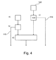
- the predetermined ablation profile 122 is adjustable in an adjustment step 142 by the user in its size, shape and/or location. This is indicated in Fig. 4 with reference numeral 120'. Further, the steps d) to f) may be repeated (not further shown) to provide updated information.
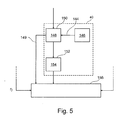
- Fig. 5 shows a further example in which step e) comprises an addition 144 of a predetermined first safety margin 146 as the safety factor to the at least one segmented tumour to generate 150 a dilated contour of the tumour 148 in a generation step 150. Further, step e) also comprises displaying the dilated contour 148, as indicated with reference numeral 149.
- step 152 the parts of the dilated contour 148 arranged outside the ablation profile are determined as critical dilated contour portions 154. Further, in step f), the critical dilated contour portions 154 are indicated in the display in an indication step 156.
- the critical dilated contour portions are indicated with a colour-coded profile (not shown).
- Fig. 6 shows a further example of a method according to the present invention, in which step d) comprises a subtraction 158 of a predetermined second safety margin 160 as the predetermined safety factor from the predetermined ablation profile to generate a limited planned ablation profile 162 in a generation step 164.
- the planned ablation profile 162 is displayed, as indicated with reference numeral 163.
- the parts of the contour arranged outside the planned ablation profile are determined as critical contour portions 168.
- the critical contour portions are indicated in the display in an indication step 170.
- the critical contour portions are indicated with a colour-coded profile.
- the ablation profile may graphically be displayed in a different way than the limited planned ablation profile.
- the segmented tumour may graphically be displayed in a first mode for areas/regions in which the planned ablation profile overlaps, and in second mode for areas/regions in which the planned ablation profile does not overlap.
- the first mode may differ from the second mode.
- the segmented tumour may be displayed in an overlaid manner together with image data of a surrounding region (not further shown).
- the image data may be X-ray image data, for example CT image data of a patient.
- Fig. 7 shows an example in which a planned insertion path 172 of an ablation target for the tumour targeting ablation is shown together with the virtual planning ablation result 140, as indicated with arrow 174.
- the indication of critical dilated contour portions and/or critical contour portions may comprise displaying the portions in a different graphical manner than the other, i.e. uncritical portions (not further shown).
- the contour may be a contour line and the dilated contour may be a dilated contour line.
- Fig. 8 shows a tumour cross-section contour in an entry point in Fig. 8B and in a progression view in Fig. 8A .
- Both figures show a background image 210 acquired by X-ray image acquisition, for example a CT-based projection of a 3D data set.
- a segmented lesion cross-sectional outline 212 is shown in two discriminating line types, with a first line type 214 and a second line type 216, which will be explained further below. Further, planned ablation isotherms 218 are shown.
- a first pattern 220 indicates a first isotherm, a second pattern 222 a second isotherm, and a third pattern 224 a third isotherm.
- the first isotherm 220 comprises two circular portions arranged in an overlapping manner, whereas the first isotherm 220 is shown in Fig. 8B in an ellipsoid form.
- Fig. 8B further shows an insertion path 226 of an interventional device for performing the ablation, for example an ablation needle.
- the needle path and the ablation profile may be specified in a user-defined arbitrary viewing plane, by specifying the target and entry points of the applicator.
- An optimal ablation profile may then be selected among a number of stored ablation profiles.
- Additional ablation applicators may be specified using the same workflow. It is also possible to position applicators in parallel to a previous selected applicator by defining the target point only.
- the isotherms representing the ablation zones are shown in cross-sections fused and blended on top of the image data. In this way, the ablation zones and the accompanied needle trajectories may be inspected at any plane position and orientation.
- the tumour coverage feedback may be implemented in open GL by first rendering the destructive ablation profile in the (non-visible) stencil buffer.
- the cross-sectional outline may be rendered twice in different colours without overlapping the stencil buffer area. This is typically done by a code snippet as:
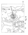
- the planned ablation volume may be shown relatively to the segmented tumour volume in a volume rendering mode, as shown in top left corner of multi-view presentation in Fig. 9 .
- the top left quadrant shows the specified isotherm of the ablation volume in a first colour 230, blended transparently over the tumour volume shown in a second colour 232.
- the margin may be added to the segmented tumour description, and the resulting volume may be referred to as planned target volume (PTV).
- PTV planned target volume
- the added margin hides/overrules the real location of the tumour boundary, which may be of importance in the neighbourhood of vessels (heat sink), where the safety margin may need to be relaxed.
- two outlines are shown, a first outline 234 of the real segmented tumour, and a second contour 236 for the planned target volume ( Fig. 10 ).
- the boundary of the segmented lesion i.e. the first line 234, may be shown in a first colour, a user controllable transparent first pattern 238, for example a transparent red ellipse, indicates the planar cross-section with an overlapping ablation profile (not further shown).
- the initial ablation profile would cover the tumour.
- a larger tumour outline is the result. This larger outline is now not fully covered by the ablation profile. Hence the respective indication by modifying the larger tumour outline
- Fig. 11 shows an alternative approach, according to which a (possibly colour-coded) safety margin is included in the isotherms specification.
- a segmented lesion arranged inside a first contra-line 334, with the inner ablation profiles, indicated with a first pattern 336, the outer ablation isotherm, indicated with a second pattern 338, will provide a safety margin.
- the outer zero degree isotherm as provided by the applicator manufacturers, will provide a natural safety margin.
- a first (zero degree) isotherm is used as mask in the colour-coded tumour boundary presentation.
- a second smaller concentric ablation profile can be constructed automatically as shown in Fig. 12 by the following observation.
- Fig. 11 shows the use of this ablation profile.
- the inner outline shows the cross-section with a segmented lesion area.
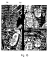
- the outer outline displays the cross-section with the dilated PTV. It is noted, when comparing Fig. 11 and Fig. 10 , that if the real tumour boundary is outside the inner ablation zone, indicated by means of a highlighted outline, the cross-section of the dilated tumour displayed in a first pattern will be outside the real predicted ablation. So instead of overlapping the dilated lesion with the predicted ablation zone, it is now to overlap the real lesion with the modified ablation profiles, and since the dilated lesion boundary has no real clinical value any more, it can be omitted. This is shown, for example, in a multi-view presentation of Fig. 13 .
- a computer program or a computer program element is provided that is characterized by being adapted to execute the method steps of the method according to one of the preceding embodiments, on an appropriate system.
- the computer program element might therefore be stored on a computer unit, which might also be part of an embodiment of the present invention.
- This computing unit may be adapted to perform or induce a performing of the steps of the method described above. Moreover, it may be adapted to operate the components of the above described apparatus.
- the computing unit can be adapted to operate automatically and/or to execute the orders of a user.
- a computer program may be loaded into a working memory of a data processor.
- the data processor may thus be equipped to carry out the method of the invention.
- This exemplary embodiment of the invention covers both, a computer program that right from the beginning uses the invention and a computer program that by means of an up-date turns an existing program into a program that uses the invention.
- the computer program element might be able to provide all necessary steps to fulfil the procedure of an exemplary embodiment of the method as described above.
- a computer readable medium such as a CD-ROM
- the computer readable medium has a computer program element stored on it which computer program element is described by the preceding section.
- a computer program may be stored and/or distributed on a suitable medium, such as an optical storage medium or a solid state medium supplied together with or as part of other hardware, but may also be distributed in other forms, such as via the internet or other wired or wireless telecommunication systems.
- a suitable medium such as an optical storage medium or a solid state medium supplied together with or as part of other hardware, but may also be distributed in other forms, such as via the internet or other wired or wireless telecommunication systems.
- the computer program may also be presented over a network like the World Wide Web and can be downloaded into the working memory of a data processor from such a network.
- a medium for making a computer program element available for downloading is provided, which computer program element is arranged to perform a method according to one of the previously described embodiments of the invention.
Landscapes
- Engineering & Computer Science (AREA)
- Health & Medical Sciences (AREA)
- Surgery (AREA)
- Life Sciences & Earth Sciences (AREA)
- Public Health (AREA)
- Robotics (AREA)
- Biomedical Technology (AREA)
- Heart & Thoracic Surgery (AREA)
- Medical Informatics (AREA)
- Molecular Biology (AREA)
- Animal Behavior & Ethology (AREA)
- General Health & Medical Sciences (AREA)
- Nuclear Medicine, Radiotherapy & Molecular Imaging (AREA)
- Veterinary Medicine (AREA)
- Human Computer Interaction (AREA)
- Architecture (AREA)
- Computer Graphics (AREA)
- Computer Hardware Design (AREA)
- General Engineering & Computer Science (AREA)
- Software Systems (AREA)
- Physics & Mathematics (AREA)
- General Physics & Mathematics (AREA)
- Theoretical Computer Science (AREA)
- Apparatus For Radiation Diagnosis (AREA)
- Surgical Instruments (AREA)
Description
- The present invention relates to tumour targeting ablation planning, and in particular to a planning device for tumour targeting ablation planning, a medical system for tumour targeting ablation, a method for tumour targeting ablation planning, as well as a computer program element, and a computer readable medium.
- Minimally invasive image-guided tumour ablation technology is becoming a viable treatment option for a variety of unresectable, or un-dissectionable, tumours, for example. The aim in tumour ablation is the complete kill of the tumour cells. Therefore, the size, shape and location of an ablation zone are evaluated during a planning step before the intervention. For example,
US 2010/0063496 A1 describes a method for planning a tumour ablation procedure. However, tumour targeting ablation planning is often planned freehand and the procedure outcome may vary from operator to operator. - For example,
WO 2011/080666 discloses an imaging system for generating an image representation of a target volume located in a patient. A segmentation unit segments a planned target volume (42) of the target volume which is to receive the ablation therapy. A planning processor (40) which generates an ablation plan with one or more ablation zones (44, 48, 50, 52) which cover the entire planned target volume (42) with ablation therapy, each ablation zone has a predetermined ablation volume, the predetermined ablation zone being defined by moving an ablation probe (12) during ablation. A robotic assembly guides or controls the ablation probe (12) along a non- stationary motion path which is defined by a trajectory, velocity and/or acceleration, and a rotation to apply ablation therapy to the target volume according to the predetermined ablation zone(s). - Thus, there is a need to provide a facilitated and improved image-based planning method.
- The object of the present invention is solved by the subject-matter of the independent claims, wherein further embodiments are incorporated in the dependent claims.
- It should be noted that the following described aspects of the invention apply also for the planning device, the medical system, the method for tumour targeting ablation planning, the computer program element and the computer readable medium.
- According to a first aspect of the present invention, a planning device for tumour targeting ablation planning is provided, comprising a processing unit, an interface unit, and a display unit. The interface unit is configured to provide at least one segmented tumour in a 3D data set to be treated in an ablation procedure. The interface unit is further configured to provide a predetermined ablation profile. The processing unit is configured to contour of the segmented tumour, to overlap the predetermined ablation profile with at least a part of the at least one segmented tumour, to identify an overlapping region, and to apply a predetermined safety factor at least to a part of the overlapping region to generate a modified overlapping region. The processing unit is further configured to determine parts of the overlapping region that are arranged outside the modified overlapping region as critical overlapping portions. The display unit is configured to display the contour of the segmented tumour, to display the predetermined ablation profile overlapped with at least a part of the at least one segmented tumour, and to display the critical overlapping portions in relation with the contour and the ablation profile as virtual planning ablation result.
- According to an exemplary embodiment of the present invention, the processing unit is configured to add a predetermined first safety margin to the at least one segmented tumour to generate a dilated contour of the tumour, and to determine the parts of the dilated contour arranged outside the ablation profile as critical dilated contour portions. The display unit is configured to display the dilated contour and to indicate the critical dilated contour portions.
- According to an exemplary embodiment of the invention, the processing unit is configured to subtract a predetermined second safety margin from the predetermined ablation profile to generate a limited planned ablation profile, and to determine the parts of the contour arranged outside the planned ablation profile as critical contour portions. The display unit is configured to display the planned ablation profile and to indicate the critical contour portions.
- According to an aspect of the invention, a user interface is provided which indicates and displays a contour of a segmented tumour and a predetermined ablation profile. Further, critical overlapping portions are displayed in relation with the contour and the ablation profile as virtual planning ablation result, wherein the critical overlapping portions relate to parts of an overlapping region which are arranged outside a modified overlapping region, which relates to an overlapping region to which a safety factor has been applied.
- According to a second aspect of the present invention, a medical system for tumour targeting ablation is provided, comprising an image acquisition unit, a planning device according to one of the above described aspects and embodiments, and an ablation unit. The image acquisition unit is configured to provide the 3D data set from which the tumour is segmented. The planning device is configured to provide an ablation path. The ablation unit is configured to apply the ablation procedure to the tumour.
- According to a third aspect of the present invention, a method for tumour targeting ablation planning is provided, comprising the following steps:
- a) providing at least one segmented tumour in a 3D data set to be treated in an ablation procedure;
- b) generating and displaying a contour of the segmented tumour;
- c) providing and displaying a predetermined ablation profile to overlap with at least a part of the at least one segmented tumour;
- d) identifying an overlapping region;
- e) applying a predetermined safety factor to at least a part of the overlapping region to generate a modified overlapping region, wherein parts of the overlapping region arranged outside the modified overlapping region are determined as critical overlapping portions; and
- f) displaying the critical overlapping portions in relation with the contour and the ablation profile as virtual planning ablation result.
- According to an exemplary embodiment, the predetermined ablation profile is adjustable by the user in its size, shape, and/or location. The steps b) to f) may be repeated to provide updated information to the user.
- According to an exemplary embodiment of the invention, step e) comprises adding a predetermined first safety margin to the at least one segmented tumour to generate a dilated contour of the tumour; displaying the dilated contour; determining the parts of the dilated contour arranged outside the ablation profile as critical dilated contour portions. In step f), the critical dilated contour portions are indicated in the display.
- According to an exemplary embodiment, step e) comprises subtracting a predetermined second safety margin from the predetermined ablation profile to generate a limited planned ablation profile; displaying the planned ablation profile; determining the part of the contour arranged outside the planned ablation profile as critical contour portions. In step f), the critical contour portions are indicated in the display.
- According to an exemplary embodiment, the segmented tumour is displayed in on overlaid manner together with image data of a surrounding region.
- According to an exemplary embodiment, a planned insertion path of an ablation target for the tumour targeting ablation is shown.
- According to a further aspect of the present invention, a planning setup is provided in which the contour of the segmented tumour is brought into relationship with an ablation profile such that, by comparing the spatial regions occupied by the segmented tumour on one side, and covered by the ablation profile on the other side, the overlapping areas are determined. Further, by applying a predetermined safety factor, an extra ablation is provided to ensure a successful ablation of the complete necrosis of the entire tumour as well as a boundary margin around the tumour, or lesion, respectively. The extra ablation is necessary to treat microscopic cancer cells surrounding the tumour and to minimize the effect of imprecise applicator placement. According to an aspect of the present invention, by identifying those parts of the overlapping region arranged outside the margin considering the extra ablation by applying the predetermined safety factor, which parts of the overlapping region are referred to as critical overlapping portions, it is possible to provide an immediate feedback to the user in form of the virtual planning ablation result in which the critical overlapping portions are displayed in relation with the contour of the segmented tumour and the ablation profile. Thus, the user is provided with an interactive tool to optimize the planned ablation procedure before starting with the procedure itself.
- For example, the user can adjust the size, shape, and/or location of the ablation profile and is immediately provided with updated planning ablation result information.
- These and other of the invention will become apparent from and elucidated with reference to the embodiments described hereinafter.
- Exemplary embodiments of the invention will be described in the following with reference to the following drawings.
-
Fig. 1 shows a planning device for tumour targeting ablation planning according to an exemplary embodiment of the present invention. -
Fig. 2 shows a medical system for tumour targeting ablation according to an exemplary embodiment of the present invention. -
Fig. 3 schematically illustrates basic steps of a method for tumour targeting ablation planning according to an exemplary embodiment of the present invention. -
Figs. 4 to 7 show further examples of methods according to the present invention. -
Figs. 8A to 8B show an example for a displayed virtual planning ablation result according to the present invention. -
Fig. 9 shows a further example of a displayed virtual planning ablation result according to an exemplary embodiment of the present invention, in relation with further ablation planning information. -
Fig. 10 shows a further example of a displayed virtual planning ablation result according to the present invention. -
Fig. 11 shows a further example of a displayed virtual planning ablation result according to the present invention. -
Fig. 12 shows further aspects in relation with the present invention. -
Fig. 13 shows a further example of a displayed virtual planning ablation result according to an exemplary embodiment of the present invention. -
Figs. 14 to 18 show the line drawings ofFigs. 8 to 11 and13 with photographic images. - Before referring to the figures, some aspects are described in the following: Due to advances in imaging technology and the availability of highly controllable medical devices, minimally invasive image-guided tumour ablation technology is becoming an important treatment option for tumours. Currently, three ablation methods are used. First, radiofrequency ablation (RF) involves the use of electrical currents in the range of radiofrequency waves through a needle that heats and destroys cancer cells. The objective is to ablate the tumour and the rim of normal tissue around its edges. Second, microwave ablation (MW) induces thermal coagulation of tissue using microwaves. The ablation diameter is less than with radiofrequency ablation, but multiple needles can be used to achieve larger ablation volumes. Tissue ablation is achieved in shorter time than compared to radiofrequency ablation. Third, cryoablation is the use of freezing gas circulating within a needle in a tumour to kill cancer cells in freeze/thaw cycles. Several needles can be used in parallel and the development of the ablative ice ball can be monitored with CT/MR/cone-beam CT, or the like. The two main challenges in tumour ablation are to achieve an accurate and reproducible applicator placement and a complete kill of intermediate and large tumours. The size of tumours has repeatedly been shown as a predictor of treatment failure. One method for the creation of larger, more complete zone of ablation is to use multiple, overlapping ablations. This requires multiple, precise applicator placements such that the ablation zones overlap. A successful ablation requires complete necrosis of the entire tumour as well as, for example, a 0.5 to 1 cm margin around the lesion. The area of the tumour and its safety margin are also referred to as the planned target volume (PTV). The size, shape, and location of the ablation zone are evaluated before interventions during the planning step. The user defines the optimal location, number and orientation of applicators to achieve a complete coverage of the PTV. The resulting ablation volume is referred to as the planned ablation volume (PAV).
- The term "tumour targeting" relates to the step during an ablation procedure that involves placement of an applicator, for example, radiofrequency electrode or cryoablation probe, into the tumour. Ideal conditions for accurate targeting include clear delineation of the tumour(s) and the surrounding anatomy through multi-planar image reconstructions, coupled with real-time imaging to visualize the applicator's and interactive capabilities.
- In an automatic radiofrequency ablation planning method, coverage of an arbitrary shaped planning target volume with multiple overlapping ellipsoid ablations is computed. However, as a problem with such automatic applicator planning method, these are generally too inflexible to tackle all the specific placement constraints. In user guided planning methods, instead of using rudimental linear measurements to define ablation areas over the targeted tumour, ablation profiles may be provided by the manufacturing companies that are shown at the tip of the planned needle path in a planning procedure. However, during the ablation planning process, the clinical user continuously interprets the clinical information to identify the boundaries of the tumour and its margin.
- According to the present invention, a flexible and reliable ablation treatment planning and tumour targeting method is proposed that provides a separation of concerns by allowing the user to first segment the tumour regions and then to use this information to plan ablation applicator positioning using tumour coverage feedback.
- For example, tumour segmentation can be fully automatic or user-assisted. The 3D interactive tumour segmentation may be based on a set of image adaptive radial functions with linear combinations of spatially localized kernels that follows image features. For example, during the segmentation, a number of control points with radius and direction (grow/shrink) are used to control the 3D segmentation process. The output of the segmentation can be a 3D vector list of the segmented volume.
- According to a further example, the segmentation can be an integrated part of the ablation planning tool. Therefore, the input control list may be stored and reused in a simple XML format. In this way based on a very small descriptive segmentation receipt stored next to the volume data, the segmentation can be simply saved, loaded, re-modified, and reused, for instance in case of overlay.
-
Fig. 1 illustrates aplanning device 10 for tumour targeting ablation planning. Thedevice 10 comprises aprocessing unit 12, aninterface unit 14, and adisplay unit 16. Theplanning device 10 is schematically indicated by a surroundingframe 18, indicating an integrated design of theplanning device 10. Of course, the individual parts of theplanning device 10 may also be provided as separate components. - The
interface unit 14 is configured to provide at least one segmented tumour in a3D data set 20 to be treated in an ablation procedure. Theinterface unit 14 is further configured to provide apredetermined ablation profile 22. - The
processing unit 12 is configured to generate acontour 24 of the segmented tumour, to overlap the predetermined ablation profile with at least a part of the at least one segmented tumour, to identify an overlapping region, to apply a predetermined safety factor at least to a part of the overlapping region to generate a modified overlapping region, and to determine parts of the overlapping region that are arranged outside the modified overlapping region as critical overlappingportions 26. - The
display unit 16 is configured to display thecontour 24 of the segmented tumour, to display thepredetermined ablation profile 22 overlapped with at least a part of the at least onesegmented tumour 20, and to display the critical overlappingportions 26 in relation with thecontour 20 and theablation profile 22 as virtualplanning ablation result 28. - The
interface unit 14 may be configured for adjusting thepredetermined ablation profile 22 by the user in its size, shape, and/or location. Theprocessing unit 12 may be configured to repeat the identification of an overlapping region, the application of a predetermined safety factor to generate an updated modified overlapping region, and the determination of parts of the overlapping region that are arranged outside the modified overlapping region as critical overlapping portions. Thedisplay unit 16 may be configured to provide updated ablation planning information. - The ablation profile may comprise a concatenation of a set of multiple profiles that are operated by multiple (mostly parallel) ablation needles.
- The
processing unit 12 may be configured to add a predetermined first safety margin to the at least one segmented tumour to generate a dilated contour of the tumour, and to determine the parts of the dilated contour arranged outside the ablation profile as critical dilated contour portions. Thedisplay unit 16 may be configured to display the dilated contour, and to indicate the critical dilated contour portions. - The
processing unit 12 may be configured to subtract the predetermined second safety margin from the predetermined ablation profile to generate a limited planned ablation profile, and to determine the parts of the contour arranged outside the planned ablation profile as critical contour portions. Thedisplay unit 16 may be configured to display the planned ablation profile and to indicate the critical contour portions. - In
Fig. 2 , amedical system 30 for tumour targeting ablation is schematically shown. Themedical system 30 comprises animage acquisition unit 32, for example a C-arm structure 34 with anX-ray source 36 at one end of a C-arm and adetector 38 at the other end of the C-arm. The C-arm structure 34 is suspended from aceiling 40 in such a way that sliding and rotational movement of the C-arm with source and detector in relation to an object 42 are possible, which object indicated with a sphere, but which can also be a patient (not further shown). Further, a patient table 44 is shown, as well as a planning device 46, which is provided according to one of the above described exemplary embodiments. Further, anablation unit 48 is schematically indicated. - The
image acquisition unit 32 is configured to provide the 3D data set from which the tumour is segmented. The planning device 46 is configured to provide an ablation path. Theablation unit 48 is configured to apply the ablation procedure to the tumour. - The image acquisition unit may be an X-ray imaging device, for example a C-arm structure, as shown, but also a CT system with a gantry, or other X-ray imaging systems. The image acquisition unit may also be an MRI- imaging device or other.
-
Fig. 3 schematically illustrates basic steps of amethod 100 for tumour targeting ablation planning. In aprovision step 110, at least one segmented tumour in a3D data set 112 is provided, wherein the segmented tumour is to be treated in an ablation procedure. In a generation anddisplay step 114, acontour 116 of the segmented tumour is generated and displayed. The displaying is indicated with a first arrow 115 (described below). In a providing and displayingstep 118, apredetermined ablation profile 120 is provided and displayed to overlap with at least a part of the at least one segmented tumour, wherein the displaying aspect of this step is indicated with asecond arrow 119. Next, in anidentification step 122, an overlappingregion 124 is identified. In anapplication step 126, apredetermined safety factor 128 is applied to at least a part of theoverlapping region 124 to generate, in ageneration step 130, a modifiedoverlapping region 132. Parts of the overlapping region arranged outside the modified overlapping region are determined in adetermination step 134 as critical overlappingportions 136. Further, in adisplay step 138, the critical overlappingportions 136 are displayed in relation with thecontour 116, as indicated withfirst arrow 115, and theablation profile 120, as indicated withsecond arrow 119, as virtualplanning ablation result 140. - The
provision step 110 is also referred to as step a), the generation anddisplay step 114 as step b), and the provision anddisplay step 118 as step c), theidentification step 122 as step d), theapplication step 126 as step e), and thedisplay step 138 as step f). - It is further noted that the method also relates to a method for operating a device comprising similar steps as the method for tumour targeting ablation planning.
- The ablation profile may be shown in cross-section with isotherms representing the ablation zones.
- As indicated in
Fig. 4 , according to a further example, thepredetermined ablation profile 122 is adjustable in anadjustment step 142 by the user in its size, shape and/or location. This is indicated inFig. 4 with reference numeral 120'. Further, the steps d) to f) may be repeated (not further shown) to provide updated information. -
Fig. 5 shows a further example in which step e) comprises anaddition 144 of a predeterminedfirst safety margin 146 as the safety factor to the at least one segmented tumour to generate 150 a dilated contour of thetumour 148 in ageneration step 150. Further, step e) also comprises displaying the dilatedcontour 148, as indicated withreference numeral 149. Next, in adetermination step 152, the parts of the dilatedcontour 148 arranged outside the ablation profile are determined as critical dilatedcontour portions 154. Further, in step f), the critical dilatedcontour portions 154 are indicated in the display in anindication step 156. - For example, the critical dilated contour portions are indicated with a colour-coded profile (not shown).
-
Fig. 6 shows a further example of a method according to the present invention, in which step d) comprises asubtraction 158 of a predeterminedsecond safety margin 160 as the predetermined safety factor from the predetermined ablation profile to generate a limited plannedablation profile 162 in ageneration step 164. The plannedablation profile 162 is displayed, as indicated withreference numeral 163. Further, in adetermination step 166, the parts of the contour arranged outside the planned ablation profile are determined ascritical contour portions 168. In step f), the critical contour portions are indicated in the display in anindication step 170. - For example, the critical contour portions are indicated with a colour-coded profile.
- The ablation profile may graphically be displayed in a different way than the limited planned ablation profile. The segmented tumour may graphically be displayed in a first mode for areas/regions in which the planned ablation profile overlaps, and in second mode for areas/regions in which the planned ablation profile does not overlap. The first mode may differ from the second mode.
- The segmented tumour may be displayed in an overlaid manner together with image data of a surrounding region (not further shown).
- The image data may be X-ray image data, for example CT image data of a patient.
-
Fig. 7 shows an example in which a plannedinsertion path 172 of an ablation target for the tumour targeting ablation is shown together with the virtualplanning ablation result 140, as indicated witharrow 174. - The indication of critical dilated contour portions and/or critical contour portions may comprise displaying the portions in a different graphical manner than the other, i.e. uncritical portions (not further shown).
- The contour may be a contour line and the dilated contour may be a dilated contour line.
-
Fig. 8 shows a tumour cross-section contour in an entry point inFig. 8B and in a progression view inFig. 8A . Both figures show abackground image 210 acquired by X-ray image acquisition, for example a CT-based projection of a 3D data set. - In
Fig. 8A, 8B , a segmented lesioncross-sectional outline 212 is shown in two discriminating line types, with afirst line type 214 and asecond line type 216, which will be explained further below. Further,planned ablation isotherms 218 are shown. Afirst pattern 220 indicates a first isotherm, a second pattern 222 a second isotherm, and a third pattern 224 a third isotherm. - In
Fig. 8A , thefirst isotherm 220 comprises two circular portions arranged in an overlapping manner, whereas thefirst isotherm 220 is shown inFig. 8B in an ellipsoid form. -
Fig. 8B further shows aninsertion path 226 of an interventional device for performing the ablation, for example an ablation needle. - During the planning, the needle path and the ablation profile may be specified in a user-defined arbitrary viewing plane, by specifying the target and entry points of the applicator. An optimal ablation profile may then be selected among a number of stored ablation profiles. Additional ablation applicators may be specified using the same workflow. It is also possible to position applicators in parallel to a previous selected applicator by defining the target point only. As mentioned above, the isotherms representing the ablation zones are shown in cross-sections fused and blended on top of the image data. In this way, the ablation zones and the accompanied needle trajectories may be inspected at any plane position and orientation.
- The tumour coverage feedback may be implemented in open GL by first rendering the destructive ablation profile in the (non-visible) stencil buffer. By using a stencil test, the cross-sectional outline may be rendered twice in different colours without overlapping the stencil buffer area. This is typically done by a code snippet as:
- glEnable(GL_STENCIL_TEST);
- SetContourColor(Vector3D(0.4, 1.0, 0.4));
- gdStencilOp(GL_KEEP, GL_KEEP, GL_KEEP);
- glStencilFunc(GL_NOTEQUAL, 0, CmodeAblation::STENCILMASK_ALL);
- DrawContours();
- glStencilFunc(GL_EQUAL, 0, CmodelAblation::STENCILMASK_ALL);
- SetContourColor(Vector3D(1.0, 0.4, 0.4));
- DrawContours();
- glDisable(GL_STENCIL_TEST);
- Additional needles may be needed for complete coverage of the tumour. By browsing through the image cross-sections, the overlap may be inspected in all various plane positions and orientations. The planned ablation volume may be shown relatively to the segmented tumour volume in a volume rendering mode, as shown in top left corner of multi-view presentation in
Fig. 9 . The top left quadrant shows the specified isotherm of the ablation volume in afirst colour 230, blended transparently over the tumour volume shown in asecond colour 232. - As mentioned above, successful ablation requires complete necrosis of the entire tumour as well as a margin around the lesion, for example a 0.5 to 1 cm margin. The margin may be added to the segmented tumour description, and the resulting volume may be referred to as planned target volume (PTV). The added margin hides/overrules the real location of the tumour boundary, which may be of importance in the neighbourhood of vessels (heat sink), where the safety margin may need to be relaxed. According to the present invention, two outlines are shown, a
first outline 234 of the real segmented tumour, and asecond contour 236 for the planned target volume (Fig. 10 ). The boundary of the segmented lesion, i.e. thefirst line 234, may be shown in a first colour, a user controllable transparentfirst pattern 238, for example a transparent red ellipse, indicates the planar cross-section with an overlapping ablation profile (not further shown). - In
Fig. 10 , the initial ablation profile would cover the tumour. By applying the safety factor to the tumour outline, according to the invention, a larger tumour outline is the result. This larger outline is now not fully covered by the ablation profile. Hence the respective indication by modifying the larger tumour outline - As an addition to showing the overlap coverage with the dilated contour, it is also possible to determine, i.e. to calculate and to display, an overlap with the "real" tumour contour, i.e. with the contour prior to applying the safety factor.
-
Fig. 11 shows an alternative approach, according to which a (possibly colour-coded) safety margin is included in the isotherms specification. By overlapping and colour-coding, a segmented lesion, arranged inside a first contra-line 334, with the inner ablation profiles, indicated with afirst pattern 336, the outer ablation isotherm, indicated with asecond pattern 338, will provide a safety margin. It is noted that in case of cryoablation, the outer zero degree isotherm, as provided by the applicator manufacturers, will provide a natural safety margin. - In
Fig. 11 , once again, the initial ablation profile would cover the tumour. By applying the safety factor to the ablation profile, according to the invention, a smaller ablation profile is the result. This smaller profile now does not fully cover the tumour. Hence the respective indication by the modification of the tumour outline. - As indicated in
Fig. 9 , a first (zero degree) isotherm is used as mask in the colour-coded tumour boundary presentation. - With radiofrequency ablation or microwave ablation, only one elliptical ablation zone may be specified. By defining the safety margin, a second smaller concentric ablation profile can be constructed automatically as shown in
Fig. 12 by the following observation. - The Origin (O) of an ellipsoid (L, W) ablation profile is defined relative to the Tip (T) of the applicator needle by the relation: O= T+ F- L/2, where F is the Front of the ablation zone extending the Tip. A smaller ellipsoid (L-M, W-M) is defined by the relation O= T+ F2 - (L-M)/2, where M is the safety margin. The ellipsoid can be made iso-centric using the equation: T+ F- L/2 = T+ F2 - (L-M)/2 → F2=M/2.
- As an example, the estimated size of the ablation zone created by means of three MWA valley Lab VT1237 percutaneous antennas that are activated at 45 W during 10 minutes at a distance of 20 mm is defined by an ellipsoid definition where L=55mm, W= 50 mm and F= 10 mm. So in this case the dimensions of the inner ellipsoid, with a 10mm safety area will be: L=45 mm, W=40 mm and F= 5mm.
- The image in
Fig. 11 shows the use of this ablation profile. The inner outline shows the cross-section with a segmented lesion area. The outer outline displays the cross-section with the dilated PTV. It is noted, when comparingFig. 11 andFig. 10 , that if the real tumour boundary is outside the inner ablation zone, indicated by means of a highlighted outline, the cross-section of the dilated tumour displayed in a first pattern will be outside the real predicted ablation. So instead of overlapping the dilated lesion with the predicted ablation zone, it is now to overlap the real lesion with the modified ablation profiles, and since the dilated lesion boundary has no real clinical value any more, it can be omitted. This is shown, for example, in a multi-view presentation ofFig. 13 . - For better understanding, the drawings of
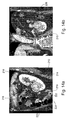
Figs. 8 to 11 and13 are also shown with photographic images inFigs. 14 to 18 . - In another exemplary embodiment of the present invention, a computer program or a computer program element is provided that is characterized by being adapted to execute the method steps of the method according to one of the preceding embodiments, on an appropriate system.
- The computer program element might therefore be stored on a computer unit, which might also be part of an embodiment of the present invention. This computing unit may be adapted to perform or induce a performing of the steps of the method described above. Moreover, it may be adapted to operate the components of the above described apparatus. The computing unit can be adapted to operate automatically and/or to execute the orders of a user. A computer program may be loaded into a working memory of a data processor. The data processor may thus be equipped to carry out the method of the invention.
- This exemplary embodiment of the invention covers both, a computer program that right from the beginning uses the invention and a computer program that by means of an up-date turns an existing program into a program that uses the invention.
- Further on, the computer program element might be able to provide all necessary steps to fulfil the procedure of an exemplary embodiment of the method as described above.
- According to a further exemplary embodiment of the present invention, a computer readable medium, such as a CD-ROM, is presented wherein the computer readable medium has a computer program element stored on it which computer program element is described by the preceding section.
- A computer program may be stored and/or distributed on a suitable medium, such as an optical storage medium or a solid state medium supplied together with or as part of other hardware, but may also be distributed in other forms, such as via the internet or other wired or wireless telecommunication systems.
- However, the computer program may also be presented over a network like the World Wide Web and can be downloaded into the working memory of a data processor from such a network. According to a further exemplary embodiment of the present invention, a medium for making a computer program element available for downloading is provided, which computer program element is arranged to perform a method according to one of the previously described embodiments of the invention.
- It has to be noted that embodiments of the invention are described with reference to different subject matters. In particular, some embodiments are described with reference to method type claims whereas other embodiments are described with reference to the device type claims. However, a person skilled in the art will gather from the above and the following description that, unless otherwise notified, in addition to any combination of features belonging to one type of subject matter also any combination between features relating to different subject matters is considered to be disclosed with this application. However, all features can be combined providing synergetic effects that are more than the simple summation of the features.
- While the invention has been illustrated and described in detail in the drawings and foregoing description, such illustration and description are to be considered illustrative or exemplary and not restrictive. The invention is not limited to the disclosed embodiments. Other variations to the disclosed embodiments can be understood and effected by those skilled in the art in practicing a claimed invention, from a study of the drawings, the disclosure, and the dependent claims.
- In the claims, the word "comprising" does not exclude other elements or steps, and the indefinite article "a" or "an" does not exclude a plurality. A single processor or other unit may fulfil the functions of several items re-cited in the claims. The mere fact that certain measures are re-cited in mutually different dependent claims does not indicate that a combination of these measures cannot be used to advantage. Any reference signs in the claims should not be construed as limiting the scope.
Claims (15)
- A planning device (10) for tumour targeting ablation planning, comprising;- a processing unit (12);- an interface unit (14); and- a display unit (16);wherein the interface unit is configured to provide at least one segmented tumour in a 3D data set (20) to be treated in an ablation procedure; and to provide a predetermined ablation profile (22);
wherein the processing unit is configured to generate a contour (24) of the segmented tumour; to overlap the predetermined ablation profile with at least a part of the at least one segmented tumour; said processing unit being characterized in that it is configured to identify an overlapping region; to apply a predetermined safety factor at least to a part of the overlapping region to generate a modified overlapping region; and to determine parts of the overlapping region that are arranged outside the modified overlapping region as critical overlapping portions (26); and
wherein the display unit is configured to display the contour of the segmented tumour; to display the predetermined ablation profile overlapped with at least a part of the at least one segmented tumour; and to display the critical overlapping portions in relation with the contour and the ablation profile as virtual planning ablation result (28). - Device according to claim 1, wherein the interface unit is configured for adjusting the predetermined ablation profile by the user in its size, shape and/or location; and
wherein the processing unit is configured to repeat the identification of an overlapping region; the application of a predetermined safety factor to generate an updated modified overlapping region; and the determination of parts of the overlapping region that are arranged outside the modified overlapping region as critical overlapping portions; and
wherein the display unit is configured to provide updated ablation planning information. - Device according to claim 1 or 2, wherein the processing unit is configured to add a predetermined first safety margin to the at least one segmented tumour to generate a dilated contour of the tumour; and to determine the parts of the dilated contour arranged outside the ablation profile as critical dilated contour portions;
wherein the display unit is configured to display the dilated contour; and to indicate the critical dilated contour portions. - Device according to one of the claims 1 to 3, wherein the processing unit is configured to subtract a predetermined second safety margin from the predetermined ablation profile to generate a limited planned ablation profile; and to determine the parts of the contour arranged outside the planned ablation profile as critical contour portions; and
wherein the display unit is configured to display the planned ablation profile;
and to indicate the critical contour portions. - A medical system (30) for tumour targeting ablation, comprising:- an image acquisition unit (32);- a planning device (46) according to one of the preceding claims; and- an ablation unit (48);wherein the image acquisition unit is configured to provide the 3D data set from which the tumour is segmented; and
wherein the planning device is configured to provide an ablation path; and
wherein the ablation unit is configured to apply the ablation procedure to the tumour. - Medical system according to claim 5, wherein the image acquisition unit is an X-ray imaging device.
- A method (100) for tumour targeting ablation planning, comprising the following steps:a) providing (110) at least one segmented tumour in a 3D data set (112) to be treated in an ablation procedure;b) generating and displaying (114) a contour (116) of the segmented tumour;c) providing and displaying (118) a predetermined ablation profile (120) to overlap with at least a part of the at least one segmented tumour; said method being characterized in that it comprises the steps ofd) identifying (122) an overlapping region (124);e) applying (126) a predetermined safety factor (128) to at least a part of the overlapping region to generate (130) a modified overlapping region (132); wherein parts of the overlapping region arranged outside the modified overlapping region are determined (134) as critical overlapping portions (136); andf) displaying (138) the critical overlapping portions in relation with the contour and the ablation profile as virtual planning ablation result (140).
- Method according to claim 7, wherein the predetermined ablation profile is adjustable (142) by the user in its size, shape and/or location; and wherein the steps d) to f) are repeated to provide updated information.
- Method according to claim 7 or 8, wherein step e) comprises:- adding (144) a predetermined first safety margin (146) to the at least one segmented tumour to generate (150) a dilated contour of the tumour (148);- displaying (149) the dilated contour;- determining (152) the parts of the dilated contour arranged outside the ablation profile as critical dilated contour portions (154); andwherein in step f), the critical dilated contour portions are indicated (156) in the display.
- Method according to claim 7, 8 or 9, wherein step e) comprises:- subtracting (158) a predetermined second safety margin (160) from the predetermined ablation profile to generate (164) a limited planned ablation profile (162);- displaying (163) the planned ablation profile;- determining (166) the parts of the contour arranged outside the planned ablation profile as critical contour portions (168); andwherein in step f), the critical contour portions are indicated (170) in the display.
- Method according to one of the claims 7 to 10, wherein the segmented tumour is displayed in an overlaid manner together with image data of a surrounding region.
- Method according to one of the claims 7 to 11, wherein a planned insertion path (172) of an ablation target for the tumour targeting ablation is shown (174).
- Method according to claim 9 to 12, wherein the indication of critical dilated contour portions and/or critical contour portions comprises displaying the portions in a different graphical manner than the other portions.
- Computer program element for controlling an apparatus according to one of the claims 1 to 6, which, when being executed by a processing unit, is adapted to perform the method steps of one of the claims 7 to 13.
- Computer readable medium having stored the program element of claim 14.
Applications Claiming Priority (2)
| Application Number | Priority Date | Filing Date | Title |
|---|---|---|---|
| US201161533815P | 2011-09-13 | 2011-09-13 | |
| PCT/IB2012/054687 WO2013038324A1 (en) | 2011-09-13 | 2012-09-10 | Ablation planning with lesion coverage feedback |
Publications (2)
| Publication Number | Publication Date |
|---|---|
| EP2744438A1 EP2744438A1 (en) | 2014-06-25 |
| EP2744438B1 true EP2744438B1 (en) | 2015-04-22 |
Family
ID=47143974
Family Applications (1)
| Application Number | Title | Priority Date | Filing Date |
|---|---|---|---|
| EP12783294.7A Active EP2744438B1 (en) | 2011-09-13 | 2012-09-10 | Ablation planning with lesion coverage feedback |
Country Status (5)
| Country | Link |
|---|---|
| US (1) | US9839482B2 (en) |
| EP (1) | EP2744438B1 (en) |
| JP (1) | JP5933723B2 (en) |
| CN (1) | CN103796607B (en) |
| WO (1) | WO2013038324A1 (en) |
Cited By (1)
| Publication number | Priority date | Publication date | Assignee | Title |
|---|---|---|---|---|
| US10643371B2 (en) | 2014-08-11 | 2020-05-05 | Covidien Lp | Treatment procedure planning system and method |
Families Citing this family (24)
| Publication number | Priority date | Publication date | Assignee | Title |
|---|---|---|---|---|
| US11264139B2 (en) * | 2007-11-21 | 2022-03-01 | Edda Technology, Inc. | Method and system for adjusting interactive 3D treatment zone for percutaneous treatment |
| KR102218244B1 (en) * | 2012-12-10 | 2021-02-22 | 인튜어티브 서지컬 오퍼레이션즈 인코포레이티드 | Collision avoidance during controlled movement of image capturing device and manipulatable device movable arms |
| WO2014197240A2 (en) | 2013-06-03 | 2014-12-11 | Nanoblate Corporation | Methods and devices for stimulating an immune response using nanosecond pulsed electric fields |
| US10925511B2 (en) | 2014-07-24 | 2021-02-23 | Cardiosolv Ablation Technologies, Inc. | System and method for cardiac ablation |
| WO2016089781A1 (en) * | 2014-12-01 | 2016-06-09 | Electroblate, Inc. | Nanoelectroablation control and vaccination |
| US10607738B2 (en) | 2015-05-15 | 2020-03-31 | University Health Network | System and method for minimally invasive thermal ablation treatment planning |
| US10548665B2 (en) | 2016-02-29 | 2020-02-04 | Pulse Biosciences, Inc. | High-voltage analog circuit pulser with feedback control |
| US10874451B2 (en) | 2016-02-29 | 2020-12-29 | Pulse Biosciences, Inc. | High-voltage analog circuit pulser and pulse generator discharge circuit |
| WO2017200954A1 (en) | 2016-05-16 | 2017-11-23 | Pulse Biosciences, Inc. | Pulse applicator |
| US10543357B2 (en) | 2016-09-19 | 2020-01-28 | Pulse Biosciences, Inc. | High voltage connectors for pulse generators |
| CN108245244B (en) * | 2016-12-28 | 2019-12-13 | 中国科学院深圳先进技术研究院 | Radio frequency ablation method and device |
| US10946193B2 (en) | 2017-02-28 | 2021-03-16 | Pulse Biosciences, Inc. | Pulse generator with independent panel triggering |
| JP6959428B2 (en) * | 2017-07-07 | 2021-11-02 | キヤノン ユーエスエイ, インコーポレイテッドCanon U.S.A., Inc | Planning for multiple probe ablation |
| US10857347B2 (en) | 2017-09-19 | 2020-12-08 | Pulse Biosciences, Inc. | Treatment instrument and high-voltage connectors for robotic surgical system |
| US11197723B2 (en) | 2017-10-09 | 2021-12-14 | Canon U.S.A., Inc. | Medical guidance system and method using localized insertion plane |
| WO2019100212A1 (en) * | 2017-11-21 | 2019-05-31 | 深圳迈瑞生物医疗电子股份有限公司 | Ultrasonic system and method for planning ablation |
| US10751128B2 (en) | 2017-11-22 | 2020-08-25 | Canon U.S.A., Inc. | Devices, systems, and methods for ablation-zone simulation and visualization |
| US10918441B2 (en) | 2017-11-22 | 2021-02-16 | Canon U.S.A., Inc. | Devices, systems, and methods for ablation-zone simulation and visualization |
| EP3749239B1 (en) * | 2018-02-05 | 2024-08-07 | Broncus Medical Inc. | Image-guided lung tumor planning and ablation system |
| CN109077801B (en) * | 2018-06-27 | 2020-06-12 | 清华大学 | Diagnosis and treatment method and system for multi-source information guided laser ablation |
| US11571569B2 (en) | 2019-02-15 | 2023-02-07 | Pulse Biosciences, Inc. | High-voltage catheters for sub-microsecond pulsing |
| CN112315579B (en) * | 2020-11-25 | 2021-07-02 | 上海睿刀医疗科技有限公司 | Electrode needle distribution device and method based on focus area |
| CN113838556A (en) * | 2021-09-24 | 2021-12-24 | 北京三春晖医疗器械有限公司 | Composite pulse electric field tumor ablation planning system |
| CN113952030B (en) * | 2021-10-28 | 2023-12-15 | 北京深睿博联科技有限责任公司 | Planning method and device for needle insertion path and ablation position of radio frequency electrode |
Family Cites Families (12)
| Publication number | Priority date | Publication date | Assignee | Title |
|---|---|---|---|---|
| US6575969B1 (en) | 1995-05-04 | 2003-06-10 | Sherwood Services Ag | Cool-tip radiofrequency thermosurgery electrode system for tumor ablation |
| US7343030B2 (en) | 2003-08-05 | 2008-03-11 | Imquant, Inc. | Dynamic tumor treatment system |
| CN1686052A (en) * | 2004-12-23 | 2005-10-26 | 中国科学院等离子体物理研究所 | Method for non-contact measurement of tumor position in chest and abdomen by radiation therapy |
| US20070129626A1 (en) | 2005-11-23 | 2007-06-07 | Prakash Mahesh | Methods and systems for facilitating surgical procedures |
| US7871406B2 (en) | 2006-08-04 | 2011-01-18 | INTIO, Inc. | Methods for planning and performing thermal ablation |
| ATE466538T1 (en) * | 2006-12-08 | 2010-05-15 | Koninkl Philips Electronics Nv | SYSTEM, METHOD AND COMPUTER READABLE MEDIUM AND USE FOR PROGRAMMING A COMBINATION THERAPY |
| US8267927B2 (en) | 2007-01-24 | 2012-09-18 | Koninklijke Philips Electronics N.V. | Advanced ablation planning |
| EP2124795B1 (en) | 2007-01-24 | 2017-05-31 | Koninklijke Philips N.V. | Rf ablation planner |
| WO2009067654A1 (en) | 2007-11-21 | 2009-05-28 | Edda Technology, Inc. | Method and system for interactive percutaneous pre-operation surgical planning |
| AT506293B1 (en) | 2008-07-16 | 2009-08-15 | Univ Innsbruck | METHOD OF ILLUSTRATING AN OBJECT AND DEVICE FOR CARRYING OUT THE METHOD |
| JP6035148B2 (en) * | 2009-12-08 | 2016-11-30 | コーニンクレッカ フィリップス エヌ ヴェKoninklijke Philips N.V. | Ablation treatment plan and device |
| WO2011080666A1 (en) | 2009-12-30 | 2011-07-07 | Koninklijke Philips Electronics N.V. | Dynamic ablation device |
-
2012
- 2012-09-10 US US14/342,444 patent/US9839482B2/en active Active
- 2012-09-10 EP EP12783294.7A patent/EP2744438B1/en active Active
- 2012-09-10 CN CN201280044278.8A patent/CN103796607B/en active Active
- 2012-09-10 WO PCT/IB2012/054687 patent/WO2013038324A1/en active Application Filing
- 2012-09-10 JP JP2014530353A patent/JP5933723B2/en active Active
Cited By (4)
| Publication number | Priority date | Publication date | Assignee | Title |
|---|---|---|---|---|
| US10643371B2 (en) | 2014-08-11 | 2020-05-05 | Covidien Lp | Treatment procedure planning system and method |
| US11227427B2 (en) | 2014-08-11 | 2022-01-18 | Covidien Lp | Treatment procedure planning system and method |
| US11238642B2 (en) | 2014-08-11 | 2022-02-01 | Covidien Lp | Treatment procedure planning system and method |
| US11769292B2 (en) | 2014-08-11 | 2023-09-26 | Covidien Lp | Treatment procedure planning system and method |
Also Published As
| Publication number | Publication date |
|---|---|
| JP2014534831A (en) | 2014-12-25 |
| US9839482B2 (en) | 2017-12-12 |
| EP2744438A1 (en) | 2014-06-25 |
| JP5933723B2 (en) | 2016-06-15 |
| US20140228835A1 (en) | 2014-08-14 |
| WO2013038324A1 (en) | 2013-03-21 |
| CN103796607A (en) | 2014-05-14 |
| CN103796607B (en) | 2017-01-18 |
Similar Documents
| Publication | Publication Date | Title |
|---|---|---|
| EP2744438B1 (en) | Ablation planning with lesion coverage feedback | |
| US10423757B2 (en) | System and method for probabilistic ablation planning | |
| CN111248998B (en) | System and method for ultrasound image guided ablation antenna placement | |
| JP5530183B2 (en) | RF Shochu Planner | |
| JP7407769B2 (en) | System and method for tumor ablation treatment planning including core tumor, margin, and healthy tissue coverage | |
| US9144461B2 (en) | Feedback system for integrating interventional planning and navigation | |
| US20130169624A1 (en) | Method for visualizing the quality of an ablation process | |
| US20170100195A1 (en) | Systems and methods for planning image-guided interventional procedures | |
| EP2519175A1 (en) | Dynamic ablation device | |
| CA2982263A1 (en) | Microwave ablation planning and procedure systems | |
| JP2007144180A (en) | Method and system for facilitating surgical procedures | |
| WO2015101545A9 (en) | Deployment modelling | |
| Ren et al. | Coverage planning in computer-assisted ablation based on genetic algorithm | |
| US11264139B2 (en) | Method and system for adjusting interactive 3D treatment zone for percutaneous treatment | |
| US20220071706A1 (en) | Ablation system with display for real-time ablation growth projection, and method therefor | |
| JP7486498B2 (en) | Apparatus for determining temperature probe position during planning for an ablation procedure - Patents.com | |
| Stoll et al. | Transfer of methods from radiotherapy planning to ablation planning with focus on uncertainties and robustness | |
| JP7421488B2 (en) | Automatic ablation antenna segmentation from CT images | |
| Liu et al. | Automated microwave ablation therapy planning with single and multiple entry points | |
| WO2024153761A1 (en) | Computer-implemented method for medical guidance of a user in the validation of a treatment dose distribution provided by a treatment planning system | |
| CN107077757A (en) | For the method and system for the interactive 3D treatment regions for adjusting transdermal therapeutic |
Legal Events
| Date | Code | Title | Description |
|---|---|---|---|
| PUAI | Public reference made under article 153(3) epc to a published international application that has entered the european phase |
Free format text: ORIGINAL CODE: 0009012 |
|
| 17P | Request for examination filed |
Effective date: 20140317 |
|
| AK | Designated contracting states |
Kind code of ref document: A1 Designated state(s): AL AT BE BG CH CY CZ DE DK EE ES FI FR GB GR HR HU IE IS IT LI LT LU LV MC MK MT NL NO PL PT RO RS SE SI SK SM TR |
|
| GRAJ | Information related to disapproval of communication of intention to grant by the applicant or resumption of examination proceedings by the epo deleted |
Free format text: ORIGINAL CODE: EPIDOSDIGR1 |
|
| GRAP | Despatch of communication of intention to grant a patent |
Free format text: ORIGINAL CODE: EPIDOSNIGR1 |
|
| DAX | Request for extension of the european patent (deleted) | ||
| INTG | Intention to grant announced |
Effective date: 20141118 |
|
| GRAS | Grant fee paid |
Free format text: ORIGINAL CODE: EPIDOSNIGR3 |
|
| GRAA | (expected) grant |
Free format text: ORIGINAL CODE: 0009210 |
|
| AK | Designated contracting states |
Kind code of ref document: B1 Designated state(s): AL AT BE BG CH CY CZ DE DK EE ES FI FR GB GR HR HU IE IS IT LI LT LU LV MC MK MT NL NO PL PT RO RS SE SI SK SM TR |
|
| REG | Reference to a national code |
Ref country code: GB Ref legal event code: FG4D |
|
| REG | Reference to a national code |
Ref country code: CH Ref legal event code: EP |
|
| REG | Reference to a national code |
Ref country code: AT Ref legal event code: REF Ref document number: 722721 Country of ref document: AT Kind code of ref document: T Effective date: 20150515 |
|
| REG | Reference to a national code |
Ref country code: IE Ref legal event code: FG4D |
|
| REG | Reference to a national code |
Ref country code: DE Ref legal event code: R096 Ref document number: 602012006930 Country of ref document: DE Effective date: 20150603 |
|
| REG | Reference to a national code |
Ref country code: NL Ref legal event code: VDEP Effective date: 20150422 |
|
| REG | Reference to a national code |
Ref country code: AT Ref legal event code: MK05 Ref document number: 722721 Country of ref document: AT Kind code of ref document: T Effective date: 20150422 |
|
| REG | Reference to a national code |
Ref country code: LT Ref legal event code: MG4D |
|
| PG25 | Lapsed in a contracting state [announced via postgrant information from national office to epo] |
Ref country code: NL Free format text: LAPSE BECAUSE OF FAILURE TO SUBMIT A TRANSLATION OF THE DESCRIPTION OR TO PAY THE FEE WITHIN THE PRESCRIBED TIME-LIMIT Effective date: 20150422 |
|
| REG | Reference to a national code |
Ref country code: FR Ref legal event code: PLFP Year of fee payment: 4 |
|
| PG25 | Lapsed in a contracting state [announced via postgrant information from national office to epo] |
Ref country code: NO Free format text: LAPSE BECAUSE OF FAILURE TO SUBMIT A TRANSLATION OF THE DESCRIPTION OR TO PAY THE FEE WITHIN THE PRESCRIBED TIME-LIMIT Effective date: 20150722 Ref country code: LT Free format text: LAPSE BECAUSE OF FAILURE TO SUBMIT A TRANSLATION OF THE DESCRIPTION OR TO PAY THE FEE WITHIN THE PRESCRIBED TIME-LIMIT Effective date: 20150422 Ref country code: HR Free format text: LAPSE BECAUSE OF FAILURE TO SUBMIT A TRANSLATION OF THE DESCRIPTION OR TO PAY THE FEE WITHIN THE PRESCRIBED TIME-LIMIT Effective date: 20150422 Ref country code: ES Free format text: LAPSE BECAUSE OF FAILURE TO SUBMIT A TRANSLATION OF THE DESCRIPTION OR TO PAY THE FEE WITHIN THE PRESCRIBED TIME-LIMIT Effective date: 20150422 Ref country code: PT Free format text: LAPSE BECAUSE OF FAILURE TO SUBMIT A TRANSLATION OF THE DESCRIPTION OR TO PAY THE FEE WITHIN THE PRESCRIBED TIME-LIMIT Effective date: 20150824 Ref country code: FI Free format text: LAPSE BECAUSE OF FAILURE TO SUBMIT A TRANSLATION OF THE DESCRIPTION OR TO PAY THE FEE WITHIN THE PRESCRIBED TIME-LIMIT Effective date: 20150422 |
|
| PG25 | Lapsed in a contracting state [announced via postgrant information from national office to epo] |
Ref country code: AT Free format text: LAPSE BECAUSE OF FAILURE TO SUBMIT A TRANSLATION OF THE DESCRIPTION OR TO PAY THE FEE WITHIN THE PRESCRIBED TIME-LIMIT Effective date: 20150422 Ref country code: IS Free format text: LAPSE BECAUSE OF FAILURE TO SUBMIT A TRANSLATION OF THE DESCRIPTION OR TO PAY THE FEE WITHIN THE PRESCRIBED TIME-LIMIT Effective date: 20150822 Ref country code: RS Free format text: LAPSE BECAUSE OF FAILURE TO SUBMIT A TRANSLATION OF THE DESCRIPTION OR TO PAY THE FEE WITHIN THE PRESCRIBED TIME-LIMIT Effective date: 20150422 Ref country code: LV Free format text: LAPSE BECAUSE OF FAILURE TO SUBMIT A TRANSLATION OF THE DESCRIPTION OR TO PAY THE FEE WITHIN THE PRESCRIBED TIME-LIMIT Effective date: 20150422 Ref country code: GR Free format text: LAPSE BECAUSE OF FAILURE TO SUBMIT A TRANSLATION OF THE DESCRIPTION OR TO PAY THE FEE WITHIN THE PRESCRIBED TIME-LIMIT Effective date: 20150723 |
|
| REG | Reference to a national code |
Ref country code: DE Ref legal event code: R097 Ref document number: 602012006930 Country of ref document: DE |
|
| PG25 | Lapsed in a contracting state [announced via postgrant information from national office to epo] |
Ref country code: DK Free format text: LAPSE BECAUSE OF FAILURE TO SUBMIT A TRANSLATION OF THE DESCRIPTION OR TO PAY THE FEE WITHIN THE PRESCRIBED TIME-LIMIT Effective date: 20150422 Ref country code: EE Free format text: LAPSE BECAUSE OF FAILURE TO SUBMIT A TRANSLATION OF THE DESCRIPTION OR TO PAY THE FEE WITHIN THE PRESCRIBED TIME-LIMIT Effective date: 20150422 |
|
| PLBE | No opposition filed within time limit |
Free format text: ORIGINAL CODE: 0009261 |
|
| STAA | Information on the status of an ep patent application or granted ep patent |
Free format text: STATUS: NO OPPOSITION FILED WITHIN TIME LIMIT |
|
| PG25 | Lapsed in a contracting state [announced via postgrant information from national office to epo] |
Ref country code: RO Free format text: LAPSE BECAUSE OF NON-PAYMENT OF DUE FEES Effective date: 20150422 Ref country code: PL Free format text: LAPSE BECAUSE OF FAILURE TO SUBMIT A TRANSLATION OF THE DESCRIPTION OR TO PAY THE FEE WITHIN THE PRESCRIBED TIME-LIMIT Effective date: 20150422 Ref country code: SK Free format text: LAPSE BECAUSE OF FAILURE TO SUBMIT A TRANSLATION OF THE DESCRIPTION OR TO PAY THE FEE WITHIN THE PRESCRIBED TIME-LIMIT Effective date: 20150422 Ref country code: CZ Free format text: LAPSE BECAUSE OF FAILURE TO SUBMIT A TRANSLATION OF THE DESCRIPTION OR TO PAY THE FEE WITHIN THE PRESCRIBED TIME-LIMIT Effective date: 20150422 |
|
| 26N | No opposition filed |
Effective date: 20160125 |
|
| PG25 | Lapsed in a contracting state [announced via postgrant information from national office to epo] |
Ref country code: MC Free format text: LAPSE BECAUSE OF FAILURE TO SUBMIT A TRANSLATION OF THE DESCRIPTION OR TO PAY THE FEE WITHIN THE PRESCRIBED TIME-LIMIT Effective date: 20150422 Ref country code: IT Free format text: LAPSE BECAUSE OF FAILURE TO SUBMIT A TRANSLATION OF THE DESCRIPTION OR TO PAY THE FEE WITHIN THE PRESCRIBED TIME-LIMIT Effective date: 20150422 Ref country code: LU Free format text: LAPSE BECAUSE OF FAILURE TO SUBMIT A TRANSLATION OF THE DESCRIPTION OR TO PAY THE FEE WITHIN THE PRESCRIBED TIME-LIMIT Effective date: 20150910 |
|
| REG | Reference to a national code |
Ref country code: CH Ref legal event code: PL |
|
| PG25 | Lapsed in a contracting state [announced via postgrant information from national office to epo] |
Ref country code: SI Free format text: LAPSE BECAUSE OF FAILURE TO SUBMIT A TRANSLATION OF THE DESCRIPTION OR TO PAY THE FEE WITHIN THE PRESCRIBED TIME-LIMIT Effective date: 20150422 |
|
| REG | Reference to a national code |
Ref country code: IE Ref legal event code: MM4A |
|
| PG25 | Lapsed in a contracting state [announced via postgrant information from national office to epo] |
Ref country code: LI Free format text: LAPSE BECAUSE OF NON-PAYMENT OF DUE FEES Effective date: 20150930 Ref country code: IE Free format text: LAPSE BECAUSE OF NON-PAYMENT OF DUE FEES Effective date: 20150910 Ref country code: CH Free format text: LAPSE BECAUSE OF NON-PAYMENT OF DUE FEES Effective date: 20150930 |
|
| PG25 | Lapsed in a contracting state [announced via postgrant information from national office to epo] |
Ref country code: BE Free format text: LAPSE BECAUSE OF FAILURE TO SUBMIT A TRANSLATION OF THE DESCRIPTION OR TO PAY THE FEE WITHIN THE PRESCRIBED TIME-LIMIT Effective date: 20150422 |
|
| REG | Reference to a national code |
Ref country code: FR Ref legal event code: PLFP Year of fee payment: 5 |
|
| PG25 | Lapsed in a contracting state [announced via postgrant information from national office to epo] |
Ref country code: MT Free format text: LAPSE BECAUSE OF FAILURE TO SUBMIT A TRANSLATION OF THE DESCRIPTION OR TO PAY THE FEE WITHIN THE PRESCRIBED TIME-LIMIT Effective date: 20150422 |
|
| PG25 | Lapsed in a contracting state [announced via postgrant information from national office to epo] |
Ref country code: HU Free format text: LAPSE BECAUSE OF FAILURE TO SUBMIT A TRANSLATION OF THE DESCRIPTION OR TO PAY THE FEE WITHIN THE PRESCRIBED TIME-LIMIT; INVALID AB INITIO Effective date: 20120910 Ref country code: BG Free format text: LAPSE BECAUSE OF FAILURE TO SUBMIT A TRANSLATION OF THE DESCRIPTION OR TO PAY THE FEE WITHIN THE PRESCRIBED TIME-LIMIT Effective date: 20150422 Ref country code: SM Free format text: LAPSE BECAUSE OF FAILURE TO SUBMIT A TRANSLATION OF THE DESCRIPTION OR TO PAY THE FEE WITHIN THE PRESCRIBED TIME-LIMIT Effective date: 20150422 |
|
| PG25 | Lapsed in a contracting state [announced via postgrant information from national office to epo] |
Ref country code: SE Free format text: LAPSE BECAUSE OF FAILURE TO SUBMIT A TRANSLATION OF THE DESCRIPTION OR TO PAY THE FEE WITHIN THE PRESCRIBED TIME-LIMIT Effective date: 20150422 Ref country code: CY Free format text: LAPSE BECAUSE OF FAILURE TO SUBMIT A TRANSLATION OF THE DESCRIPTION OR TO PAY THE FEE WITHIN THE PRESCRIBED TIME-LIMIT Effective date: 20150422 |
|
| REG | Reference to a national code |
Ref country code: FR Ref legal event code: PLFP Year of fee payment: 6 |
|
| PG25 | Lapsed in a contracting state [announced via postgrant information from national office to epo] |
Ref country code: TR Free format text: LAPSE BECAUSE OF FAILURE TO SUBMIT A TRANSLATION OF THE DESCRIPTION OR TO PAY THE FEE WITHIN THE PRESCRIBED TIME-LIMIT Effective date: 20150422 Ref country code: MK Free format text: LAPSE BECAUSE OF FAILURE TO SUBMIT A TRANSLATION OF THE DESCRIPTION OR TO PAY THE FEE WITHIN THE PRESCRIBED TIME-LIMIT Effective date: 20150422 |
|
| REG | Reference to a national code |
Ref country code: FR Ref legal event code: PLFP Year of fee payment: 7 |
|
| PG25 | Lapsed in a contracting state [announced via postgrant information from national office to epo] |
Ref country code: AL Free format text: LAPSE BECAUSE OF FAILURE TO SUBMIT A TRANSLATION OF THE DESCRIPTION OR TO PAY THE FEE WITHIN THE PRESCRIBED TIME-LIMIT Effective date: 20150422 |
|
| PGFP | Annual fee paid to national office [announced via postgrant information from national office to epo] |
Ref country code: DE Payment date: 20240926 Year of fee payment: 13 |
|
| PGFP | Annual fee paid to national office [announced via postgrant information from national office to epo] |
Ref country code: GB Payment date: 20240924 Year of fee payment: 13 |
|
| PGFP | Annual fee paid to national office [announced via postgrant information from national office to epo] |
Ref country code: FR Payment date: 20240925 Year of fee payment: 13 |