JP5931735B2 - System and method for pipe joints - Google Patents
System and method for pipe joints Download PDFInfo
- Publication number
- JP5931735B2 JP5931735B2 JP2012536926A JP2012536926A JP5931735B2 JP 5931735 B2 JP5931735 B2 JP 5931735B2 JP 2012536926 A JP2012536926 A JP 2012536926A JP 2012536926 A JP2012536926 A JP 2012536926A JP 5931735 B2 JP5931735 B2 JP 5931735B2
- Authority
- JP
- Japan
- Prior art keywords
- gasket
- housing
- defines
- cavity
- coupling
- Prior art date
- Legal status (The legal status is an assumption and is not a legal conclusion. Google has not performed a legal analysis and makes no representation as to the accuracy of the status listed.)
- Active
Links
Images


Classifications
-
- F—MECHANICAL ENGINEERING; LIGHTING; HEATING; WEAPONS; BLASTING
- F16—ENGINEERING ELEMENTS AND UNITS; GENERAL MEASURES FOR PRODUCING AND MAINTAINING EFFECTIVE FUNCTIONING OF MACHINES OR INSTALLATIONS; THERMAL INSULATION IN GENERAL
- F16L—PIPES; JOINTS OR FITTINGS FOR PIPES; SUPPORTS FOR PIPES, CABLES OR PROTECTIVE TUBING; MEANS FOR THERMAL INSULATION IN GENERAL
- F16L17/00—Joints with packing adapted to sealing by fluid pressure
- F16L17/02—Joints with packing adapted to sealing by fluid pressure with sealing rings arranged between outer surface of pipe and inner surface of sleeve or socket
- F16L17/04—Joints with packing adapted to sealing by fluid pressure with sealing rings arranged between outer surface of pipe and inner surface of sleeve or socket with longitudinally split or divided sleeve
-
- F—MECHANICAL ENGINEERING; LIGHTING; HEATING; WEAPONS; BLASTING
- F16—ENGINEERING ELEMENTS AND UNITS; GENERAL MEASURES FOR PRODUCING AND MAINTAINING EFFECTIVE FUNCTIONING OF MACHINES OR INSTALLATIONS; THERMAL INSULATION IN GENERAL
- F16L—PIPES; JOINTS OR FITTINGS FOR PIPES; SUPPORTS FOR PIPES, CABLES OR PROTECTIVE TUBING; MEANS FOR THERMAL INSULATION IN GENERAL
- F16L21/00—Joints with sleeve or socket
- F16L21/06—Joints with sleeve or socket with a divided sleeve or ring clamping around the pipe-ends
- F16L21/065—Joints with sleeve or socket with a divided sleeve or ring clamping around the pipe-ends tightened by tangentially-arranged threaded pins
-
- F—MECHANICAL ENGINEERING; LIGHTING; HEATING; WEAPONS; BLASTING
- F16—ENGINEERING ELEMENTS AND UNITS; GENERAL MEASURES FOR PRODUCING AND MAINTAINING EFFECTIVE FUNCTIONING OF MACHINES OR INSTALLATIONS; THERMAL INSULATION IN GENERAL
- F16J—PISTONS; CYLINDERS; SEALINGS
- F16J15/00—Sealings
- F16J15/02—Sealings between relatively-stationary surfaces
-
- F—MECHANICAL ENGINEERING; LIGHTING; HEATING; WEAPONS; BLASTING
- F16—ENGINEERING ELEMENTS AND UNITS; GENERAL MEASURES FOR PRODUCING AND MAINTAINING EFFECTIVE FUNCTIONING OF MACHINES OR INSTALLATIONS; THERMAL INSULATION IN GENERAL
- F16L—PIPES; JOINTS OR FITTINGS FOR PIPES; SUPPORTS FOR PIPES, CABLES OR PROTECTIVE TUBING; MEANS FOR THERMAL INSULATION IN GENERAL
- F16L17/00—Joints with packing adapted to sealing by fluid pressure
- F16L17/06—Joints with packing adapted to sealing by fluid pressure with sealing rings arranged between the end surfaces of the pipes or flanges or arranged in recesses in the pipe ends or flanges
-
- F—MECHANICAL ENGINEERING; LIGHTING; HEATING; WEAPONS; BLASTING
- F16—ENGINEERING ELEMENTS AND UNITS; GENERAL MEASURES FOR PRODUCING AND MAINTAINING EFFECTIVE FUNCTIONING OF MACHINES OR INSTALLATIONS; THERMAL INSULATION IN GENERAL
- F16L—PIPES; JOINTS OR FITTINGS FOR PIPES; SUPPORTS FOR PIPES, CABLES OR PROTECTIVE TUBING; MEANS FOR THERMAL INSULATION IN GENERAL
- F16L21/00—Joints with sleeve or socket
- F16L21/002—Sleeves or nipples for pipes of the same diameter; Reduction pieces
- F16L21/005—Sleeves or nipples for pipes of the same diameter; Reduction pieces made of elastic material, e.g. partly or completely surrounded by clamping devices
-
- Y—GENERAL TAGGING OF NEW TECHNOLOGICAL DEVELOPMENTS; GENERAL TAGGING OF CROSS-SECTIONAL TECHNOLOGIES SPANNING OVER SEVERAL SECTIONS OF THE IPC; TECHNICAL SUBJECTS COVERED BY FORMER USPC CROSS-REFERENCE ART COLLECTIONS [XRACs] AND DIGESTS
- Y10—TECHNICAL SUBJECTS COVERED BY FORMER USPC
- Y10T—TECHNICAL SUBJECTS COVERED BY FORMER US CLASSIFICATION
- Y10T29/00—Metal working
- Y10T29/49—Method of mechanical manufacture
- Y10T29/49826—Assembling or joining
Description
関連出願の相互参照
本国際出願は、2009年10月27日出願の米国仮特許出願第61/255,409号(「Systems and Methods for Pipe Couplings」)の優先権の利益を主張し、その全体を参照として援用する。
CROSS REFERENCE TO RELATED APPLICATIONS This international application claims the benefit of priority of US Provisional Patent Application No. 61 / 255,409 filed Oct. 27, 2009 ("Systems and Methods for Pipe Couplings"), in its entirety. Is incorporated by reference.
本発明は、一般的に管取付具に関し、さらに具体的には、流体を搬送する配管またはチューブを結合する装置および方法に関する。 The present invention relates generally to tube fittings, and more specifically to an apparatus and method for coupling pipes or tubes carrying fluids.
管またはチューブセグメントを接合するための好ましい結合構成およびそれらの構成要素が提供される。好ましい1つの実施形態では、結合部は、ハウジング;および管継手の周りにシールを形成するための、ハウジング内に配置されたガスケットを含んで提供される。ガスケットは環状またはリングタイプの本体であり、第1の側面と、第1の側面から離間した第2の側面であって、それら側面の間に中間軸を規定する第2の側面とを有する。ガスケットの外面または周囲面およびガスケットの内面は、第1の側面と第2の側面との間に延在して、中間軸によって二等分される。内面は、好ましくは第1のシーリングリップおよび第2のシーリングリップを規定する。第1および第2のシーリングリップは、好ましくは、中間軸の周りに配置されて、第1のシーリングリップと中間軸との間に延在する内面の第1の移行部分、および第2のシーリングリップと中間軸との間の第2の移行部分を規定する。第1および第2の移行部分は、シーリングリップから中間軸および周囲壁に向かう方向に延在するので、各々、好ましくは正の傾斜を規定する。一層好ましくは、ガスケットの内面は、中間軸に沿って延在する中心脚を規定する。さらに、移行部分は、ガスケット本体の厚さが側面から中間軸または中心脚への方向に小さくなるように提供する。 Preferred coupling arrangements and their components for joining tubes or tube segments are provided. In one preferred embodiment, the coupling is provided including a housing; and a gasket disposed within the housing for forming a seal around the fitting. The gasket is an annular or ring type body having a first side surface and a second side surface spaced from the first side surface, the second side surface defining an intermediate shaft between the side surfaces. The outer or peripheral surface of the gasket and the inner surface of the gasket extend between the first side surface and the second side surface and are bisected by the intermediate shaft. The inner surface preferably defines a first sealing lip and a second sealing lip. The first and second sealing lips are preferably disposed about the intermediate shaft, the first transition portion of the inner surface extending between the first sealing lip and the intermediate shaft, and the second sealing A second transition between the lip and the intermediate shaft is defined. Since the first and second transition portions extend in a direction from the sealing lip toward the intermediate shaft and the surrounding wall, each preferably defines a positive slope. More preferably, the inner surface of the gasket defines a central leg that extends along the intermediate axis. Furthermore, the transition portion provides that the thickness of the gasket body decreases in the direction from the side to the intermediate shaft or central leg.
第1の側面、第1の側面から離間した第2の側面であって、それらの間に中間軸を規定する第2の側面を含む別の好ましいガスケットが提供される。ガスケットは、周囲面および内面を含み、それらの各々が、第1の側面と第2の側面との間に延在して、中間軸によって二等分さされる。周囲面は、好ましくは、中間軸の周りに配置された一対の丸みをつけられた(radiused)端部部分を有するプロファイルを規定し、2つの丸みをつけられた端部部分の間には中央部分が延在し、丸みをつけられた端部部分は、ガスケットの最大直径を規定する。一実施形態では、中央部分は、中間軸と交差するアーチ形プロファイルを規定する。あるいは、中央部分のプロファイルは実質的に線形である。別の好ましい実施形態では、ガスケットの内面は、第1のシーリングリップおよび第2のシーリングリップを規定し、第1および第2のシーリングリップは、中間軸の周りに配置され、内面は、第1および第2のシーリングリップの一方から中間軸および周囲壁に向かう方向に延在して正の傾斜を規定する移行部分を含む。 Another preferred gasket is provided that includes a first side, a second side spaced from the first side, the second side defining an intermediate shaft therebetween. The gasket includes a peripheral surface and an inner surface, each of which extends between the first side and the second side and is bisected by the intermediate shaft. The peripheral surface preferably defines a profile having a pair of radiused end portions disposed about the intermediate axis, and is central between the two rounded end portions. The end portion, with the portion extending and rounded, defines the maximum diameter of the gasket. In one embodiment, the central portion defines an arcuate profile that intersects the intermediate axis. Alternatively, the profile of the central portion is substantially linear. In another preferred embodiment, the inner surface of the gasket defines a first sealing lip and a second sealing lip, the first and second sealing lips being disposed about the intermediate shaft, the inner surface being the first And a transition portion extending in a direction from one of the second sealing lips toward the intermediate shaft and the peripheral wall to define a positive slope.
好ましい結合構成において使用するための好ましいハウジングは、第1の管セグメントを収容するための第1の側面と、第2の管セグメントを収容するための第2の側面とを含む。第2の側面は第1の側面から離間して、ハウジングの中間軸を規定する。ハウジングは、ガスケットを係合するためのキャビティを規定する内面を含み、および第1の側面と第2の側面との間に延在して、側面から中間軸への方向に小さくなる内径プロファイルを規定し、ガスケットを係合する接点の直径を規定する。ハウジングのキャビティに配置された好ましいガスケットは、接点の直径よりも大きい直径を有する。好ましい1つの実施形態では、内面は、接点の直径以下である、ハウジングの内側の直径を有する。 A preferred housing for use in a preferred coupling configuration includes a first side for receiving a first tube segment and a second side for receiving a second tube segment. The second side is spaced from the first side and defines an intermediate shaft of the housing. The housing includes an inner surface defining a cavity for engaging the gasket, and extends between the first side and the second side to have an inner diameter profile that decreases in the direction from the side to the intermediate shaft. Define the diameter of the contact that engages the gasket. A preferred gasket disposed in the cavity of the housing has a diameter that is greater than the diameter of the contact. In one preferred embodiment, the inner surface has an inner diameter of the housing that is less than or equal to the diameter of the contact.
ハウジングの好ましい1つの実施形態では、内面は、側壁部分;背壁部分;および側壁部分と背壁部分との間の移行部分を含む。移行部分は、好ましくは、一方の側面から中間軸への方向に負の傾斜を規定し、および第1の丸みをつけられた部分、第2の丸みをつけられた部分を含み、第1の丸みをつけられた部分と第2の丸みをつけられた部分との間には直線セグメントが延在する。直線セグメントは、好ましい負の傾斜を規定する。 In one preferred embodiment of the housing, the inner surface includes a side wall portion; a back wall portion; and a transition portion between the side wall portion and the back wall portion. The transition portion preferably defines a negative slope in a direction from one side to the intermediate axis, and includes a first rounded portion, a second rounded portion, A straight segment extends between the rounded portion and the second rounded portion. The straight line segment defines a preferred negative slope.
管継手の好ましいシーリング方法が提供され、これは、ハウジング構成要素の内面によって規定されたキャビティ内に配置されたガスケット上のハウジング構成要素のテーパ付き内面を半径方向に圧縮するステップを含む。ガスケットは、中間軸、変曲点、および変曲点と中間軸との間の線形セグメントを有する。線形セグメントは、好ましくは、中間軸に向かう方向において正の傾斜を規定する。好ましい方法は、中間軸と変曲点との間に、テーパ付き表面によって規定されたノッチを、低い点に配置して、圧縮によって、ガスケットの側方部分をハウジングの側壁に対して動かすステップをさらに含む。 A preferred method for sealing a fitting is provided, which includes radially compressing the tapered inner surface of the housing component on a gasket disposed in a cavity defined by the inner surface of the housing component. The gasket has an intermediate axis, an inflection point, and a linear segment between the inflection point and the intermediate axis. The linear segment preferably defines a positive slope in the direction towards the intermediate axis. A preferred method comprises placing a notch defined by a tapered surface between the intermediate shaft and the inflection point at a low point and moving the side portion of the gasket relative to the side wall of the housing by compression. In addition.
別の好ましい結合部は、ガスケットと、第1の側面、および第1の側面から離間してハウジングの中間軸を規定する第2の側面を有するハウジングとを含む。ハウジングは、ガスケットを係合するためのキャビティを規定する内面を含み、および第1の側面と第2の側面との間に延在して、側面の少なくとも一方と中間軸との間の少なくとも一部分で小さくなる内径プロファイルを規定する。内面は、側壁部分、背壁部分、および側壁部分と背壁部分との間の移行部分を含む。移行部分は、好ましくは、一方の側面から中間軸への方向に負の傾斜を規定し、および第1の丸みをつけられた部分、第2の丸みをつけられた部分を含み、第1の丸みをつけられた部分と第2の丸みをつけられた部分との間には直線セグメントが延在する。直線セグメントは負の傾斜を規定し、第1の丸みをつけられた部分は、直線の一方の側に配置された曲率中心を有し、第2の丸みをつけられた部分は、直線の他方の側に配置された曲率中心を有し、第1の丸みをつけられた部分は、ハウジングの第1のキャビティの深さを規定し、および第2の丸みをつけられた部分は、第1のキャビティの深さよりも小さい第2のキャビティの深さを規定し、背壁部分は、第2のキャビティの深さと等しい第3のキャビティの深さを規定する。好ましいガスケットは、第1の側面と、第1の側面から離間して、ガスケット中間軸を規定する第2の側面とを含む。好ましいガスケットは外面および内面を含み、内面は第1の側面と第2の側面との間に延在して、中間軸によって二等分される。内面は、第1のシーリングリップおよび第2のシーリングリップを規定し、第1および第2のシーリングリップは、中間軸の周りに配置される。内面は、シーリングリップから中間軸および周囲壁へ向かう方向に延在して好ましくは正の傾斜を規定する移行部分を含む。外面は、ガスケットのガスケット中間軸の周りに配置された一対の拡大端部部分を含むプロファイルを規定し、それらの間に中央部分が配置される。中央部分は、好ましくは拡大端部部分の半径方向内側であり、ハウジングの背壁部分に係合する。 Another preferred coupling includes a gasket and a housing having a first side and a second side spaced from the first side and defining an intermediate axis of the housing. The housing includes an inner surface defining a cavity for engaging the gasket, and extends between the first side and the second side, and at least a portion between at least one of the side surfaces and the intermediate shaft. The inner diameter profile which becomes smaller is defined. The inner surface includes a sidewall portion, a back wall portion, and a transition portion between the sidewall portion and the back wall portion. The transition portion preferably defines a negative slope in a direction from one side to the intermediate axis, and includes a first rounded portion, a second rounded portion, A straight segment extends between the rounded portion and the second rounded portion. The straight line segment defines a negative slope, the first rounded portion has a center of curvature located on one side of the straight line, and the second rounded portion is the other side of the straight line The first rounded portion having a center of curvature located on the side of the housing defines the depth of the first cavity of the housing, and the second rounded portion is the first rounded portion. A depth of the second cavity that is less than the depth of the first cavity, and the back wall portion defines a depth of the third cavity that is equal to the depth of the second cavity. A preferred gasket includes a first side and a second side spaced from the first side and defining a gasket intermediate shaft. A preferred gasket includes an outer surface and an inner surface, the inner surface extending between the first side and the second side and bisected by an intermediate shaft. The inner surface defines a first sealing lip and a second sealing lip, and the first and second sealing lips are disposed about the intermediate shaft. The inner surface includes a transition portion extending in a direction from the sealing lip toward the intermediate shaft and the peripheral wall, preferably defining a positive slope. The outer surface defines a profile that includes a pair of enlarged end portions disposed about the gasket intermediate axis of the gasket, with a central portion disposed therebetween. The central portion is preferably radially inward of the enlarged end portion and engages the back wall portion of the housing.
本明細書に組み込まれ、かつ本明細書の一部を構成する添付の図面は、本発明の例示的な実施形態を示し、上述の説明と併せて、本発明の特徴を説明するのに役立つ。 The accompanying drawings, which are incorporated in and constitute a part of this specification, illustrate exemplary embodiments of the invention and, together with the above description, serve to explain the features of the invention. .
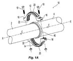
図1A、図1Bおよび図2A、図2Bに、好ましい結合構成10を使用する、好ましい管またはチューブ継手組立体の形態を示す。好ましい継手組立体では、管またはチューブの端部セグメント2、4は管軸X−Xに沿って軸方向に整列され、およびガスケット40が端部セグメント2、4の周りに配置される。管またはチューブは銅、鋼、または継手組立体を形成する他のチューブ状材料としてよい。少なくとも2つのハウジング構成要素12、14を有する好ましい結合部ハウジングが、ガスケット40の周りに係合される。ハウジング構成要素は、図1Aから分かるように別個の構成要素としてもよいし、代わりに、結合された構成に、例えば図2Aおよび2Bに示すヒンジタイプの構成に予め組み立てられてもよい。結合構成に使用する好ましい1つのヒンジ結合部は、2009年10月27日出願の米国仮特許出願第61/255,351号明細書(「Systems and Methods for Hinge Couplings」)に示され、説明されており、その全体を参照として援用する。ハウジング構成要素は、X−Xの周りで互いに対して鏡面対称となるように構造において同一であっても、または代わりに、互いに対して係合または整列するように構成されてガスケット40の周りで完全な結合部ハウジングを形成する限り、異なって構成されてもよい。さらに、結合部ハウジングは、例えば、米国特許第6,139,069号明細書(その全体を参照として援用する)から分かるように、ガスケット40を効果的に係合して管継手を形成するために構成要素を連結できることを条件として、3つ以上の構成要素によって形成できる。
1A, 1B and 2A, 2B illustrate a preferred tube or tube fitting assembly configuration that uses the
一般的に、ハウジング構成要素12、14の各々は、第1の端部16、第2の端部18を有し、好ましくは第1の端部16と第2の端部18との間にはアーチ形セグメント20が延在して、ガスケット40と係合する。ハウジングを形成する構成要素数に依存して、セグメントは半円、4分の1円とすることができるか、または別のアーク長を規定できる。端部16、18は、好ましくは貫通孔を有するボルトパッド延在部として構成され、貫通孔をには締結具19が配置されて、ハウジング構成要素12、14を互いに固定および/または結合する。管係合セグメント20は、ガスケット40を係合して収容するガスケット用キャビティ24を規定する内面22をさらに含む。
Generally, each
管継手の形成を完了するために、ハウジング構成要素12、14は、ガスケット40を覆って配置される。流体密封を形成するために、締結具は、ハウジング12、14を結び付けるように締められる。構成要素12、14が結び付けられると、構成要素の内面22は、ガスケット40を圧縮して流体密封を形成する。圧縮された組立体は、管軸X−Xと同軸上に整列される結合構成10の中心軸C−Cを規定する。
To complete the formation of the fitting, the
図3Aおよび図3Bの各々には、ハウジング構成要素12の内面22とガスケット40との間の表面接触係合を示す、好ましい管継手組立体の圧縮されていない図および圧縮された図を示す。好ましくは、結合構成10は、結合部10の中心軸C−Cに垂直に延在する中間軸A−Aの周りで対称的である。あるいは、例えば、径違い(reduced)管継手構成の場合のように、構成は非対称とすることができる。好ましいハウジング12およびその内面22は、好ましい表面プロファイル106を規定する。表面プロファイル106は、好ましくは、中間軸A−Aの方へ内側へテーパが付けられる部分を含んで、内径の減少を規定し、かつ中間軸A−Aの周りに配置された1つ以上のノッチ30を形成する。あるいは、ノッチ30は、中間軸A−Aの周りで内面22に形成された三角形によって規定することができ、ここでは、頂点は、キャビティ24に半径方向内側に延在する。図3Bの圧縮された図を参照すると、内面22およびそのプロファイル106は、ガスケット40の周囲面に係合して半径方向圧縮力を加える。ノッチ30およびそのテーパ付き面は、内側テーパ付き面22の内径を規定する点P0を含み、内径は、点P0が接触する個所においてガスケット40の直径よりも小さい。それゆえ、結合構成10を備える管継手に流体密封を形成する場合、ノッチ30が接触点P0においてガスケット40を、好ましくは軸C−Cに向かって半径方向に変形させる。ガスケット40に内部チャネル58があるために、ガスケット40の側方部分は、チャネル58のプロファイルに沿って点P1において折れ曲がり、管セグメント2、4の外表面とシール係合を形成し、およびガスケット40の側方部分は、ハウジング12の内面22に対して横方向に移動する。管継手の内部流圧は、ガスケット40の中央部分を半径方向外側に動かして、ガスケット用キャビティ24の最も深い部分でハウジングの内面22に接触し、キャビティ24内のガスケット40の位置をさらに安定化させる。好ましい結合構成10の場合、ノッチ30の形態は、好ましくは、中間軸A−Aに対してガスケットの変曲点P1の内側に(medially)接触点P0を配置し、接触点P0が変曲点P1の内側(medial)となるようにする。さらに、点P0は、好ましくは、結合部ハウジングに対してガスケットを半径方向外側に動かす内部流圧の能力を最小限にしないまたはそれをなくさないように配置される。
Each of FIGS. 3A and 3B shows an uncompressed view and a compressed view of a preferred fitting assembly showing surface contact engagement between the
図3Aは、第1の側面100および第2の側面102を有する好ましいハウジング構成要素12の全体的な断面図を示し、第1の側面100と第2の側面102との間にハウジング構成要素12の中間軸A−Aを規定する。第1の側面と第2の側面との間には、周囲面プロファイル104(図4Aおよび図4Bに104’および104”で示す)と、内面22の好ましい内面プロファイル106とを含む構成要素12の本体が延在する。内面106は、好ましくは中間軸A−Aの両側に、管係合部分108(図4Aおよび図4Bに108’および108”で示す)、側壁部分110、背壁部分112、および側壁部分110と背壁部分112との間に延在する移行部分114を含む。管係合部分108は、管継手組立体において管セグメントの外表面に直接係合し、好ましくは、結合構成10の中心軸C−Cに対し実質的に直線的にかつ平行に延在する。側壁部分110は管係合部分108と隣接し、継手組立体においてガスケット40の側壁と係合する面を規定する。側壁部分110はまた、好ましくは、中間軸A−−Aに平行な線と好ましくは鈍角αを規定する実質的に線形である。一層好ましくは管係合部分108と側壁部分110との間には表面移行部109が形成され、これは、曲率半径を規定することによって丸みをつけられ得るか、または一層好ましくは管係合部分108と側壁部分110との間に段移行部を規定する。
FIG. 3A shows an overall cross-sectional view of a
内面プロファイル106の背壁部分112は、好ましくは、ガスケット40の内側部分を支持するハウジング内面22の部分を規定し、一層好ましくは、ガスケット用キャビティ24の最も深い部分を規定する。あるいは、背壁112は、ノッチ30の接触点P0と同等の深さのところに、またはP0よりも浅いがガスケットの点P1よりも深いところに配置できる。好ましい実施形態12では、内面106プロファイルの背壁部分112は、結合部10の中心軸C−Cに平行な方向に延在して実質的に線形であるかまたは平面的である。あるいは、背壁部分112は、ガスケット40と係合するために内面104の単一の最も深い接触点とし得る。さらに代替形態では、背壁部分112は、ガスケット40用の複数の接触点を規定する内面106のセグメントを規定でき、複数の接触点は、ガスケット40を係合するガスケット用キャビティの最も深い点を規定する。
The
内面プロファイル106の背壁部分112と側壁部分110との間に移行部分114が隣接して延在する。移行部分114は、好ましくは、側壁部分110に隣接する曲率半径を規定する第1の丸みをつけられた端部114aと、背壁部分112に隣接する曲率半径を規定する第2の丸みをつけられた端部114bとを含む。あるいは、端部114a、114bは、むしろ階段タイプの移行部とすることができる。移行部分114は、端部114aと114bとの間に、好ましくは上述の内面22のノッチ30を規定する。好ましくは、移行部分114は、負の傾斜を有する内面プロファイル106のセグメント114cを規定する、つまり、側面100、102から中間軸A−Aの方向において、ガスケット用キャビティ24の深さは、横から内側への方向において傾斜セグメント14cの長さにわたって浅くなる。それゆえ、セグメント114cは、横から内側への方向において結合部のハウジング構成要素12のための内面プロファイル106の細くなるテーパを規定して、セグメント114cにわたるハウジングの内径の低減を規定する。セグメント114cは、好ましくは線形であるか、または代わりに、セグメントが、ガスケット40に接触するハウジング構成要素12の内面22の領域において細くなるテーパを規定することを条件に、その長さにわたって、起伏または他の非線形プロファイルによって規定してもよい。内面プロファイル106の移行部分114は、移行部分114が上述のようにノッチ30を効果的に規定することを条件に、線形セグメントと非線形セグメントとの組み合わせを含むことができる。
A
図4Aに、好ましい公称6インチ(6in.)の結合部10’のための好ましいハウジング構成要素12’を示す。構成要素は、互いに離間した第1の側面100’および第2の側面102’を含み、ハウジング構成要素12’の中間軸A’−A’を規定する。側面100’、102’は、中間軸A’−A’を中心とした結合部10’の幅Wを規定し、幅Wは、好ましくは約1.5〜約3インチの範囲とし、約1.8インチである。ハウジング構成要素12’は、結合部組立体10’の外表面を規定する周囲面104’を含む。ハウジング構成要素12’は内面プロファイル106’をさらに含み、ガスケット40を収容するためのガスケット用キャビティ24’を規定する。好ましい内面プロファイル106’は、中間軸A’−A’の周りで対称的であり、その側方端部に、管係合面108’を含む。内面プロファイル106’は、内側に延在する側壁部分110’をさらに含み、管係合部分108’と側壁部分110’との間に実質的に段移行部109’を備える。側壁セグメント110’は、好ましくは正の傾斜を備える線形であり、ガスケット用キャビティ24の深さが、側壁セグメント110’の長さにわたって横から内側への方向において増大する。側壁セグメントは、さらに、好ましくは、中間軸A’−A’に平行な線に対して好ましい角度α’を約20度(20°)に規定する。側壁セグメント110’は、中間軸A’−A’の周りで離間しており、ガスケット40の厚さに適合する。
FIG. 4A shows a preferred housing component 12 'for a preferred nominal 6 inch (6 in.) Coupling 10'. The component includes a first side surface 100 'and a second side surface 102' spaced apart from each other and defines an intermediate axis A'-A 'of the housing component 12'. The side surfaces 100 ', 102' define a width W of the joint 10 'about the intermediate axis A'-A', the width W preferably being in the range of about 1.5 to about 3 inches, about 1 .8 inches. The housing component 12 'includes a peripheral surface 104' that defines the outer surface of the coupling assembly 10 '. The
ハウジング構成要素12’の内面プロファイル106’の背壁部分は、好ましくは、ガスケット用キャビティ24’の最も深い深さHmaxを規定し、これは、好ましくは、管係合面108’の平面に配置されたベースラインBから約1/2インチ(0.5インチ)である。完全な結合部組立体10では、背壁部分112は、好ましくは約7インチ(7in.)である結合部10’の最大内径を規定する。背壁部分112は、好ましくは、結合部の軸C−Cに平行に線形的に延在して、キャビティ24の最小幅を規定する。
The back wall portion of the inner profile 106 'of the housing component 12' preferably defines the deepest depth Hmax of the gasket cavity 24 ', which is preferably located in the plane of the tube engaging surface 108'. About 1/2 inch (0.5 inch) from the baseline B. In the complete
側壁部分110’と背壁部分112’との間には移行部分114’が延在する。移行部分114’は、好ましくは、側壁部分110’に隣接する第1の丸みをつけられた部分114’aと、背壁部分112’に隣接する第2の丸みをつけられた部分114’bとを含む。移行部分114’は、好ましくは、点P’1とP’2との間の、横から内側への方向において、内面22’の細くテーパ付けされた部分を規定する線形セグメント114’cを含み、ノッチ30’、およびセグメント114c’にわたって減少する内径を規定する。点P’1は、好ましくは側壁部分110’の端部に配置され、および凹状の丸みをつけられた部分114’aは、0.1インチ未満、好ましくは約0.06インチの好ましい曲率半径を有する。点P2は、線形セグメント114’cの端部に配置され、かつ0.1インチ未満、好ましくは約0.06インチの曲率半径を有する凸状の丸みをつけられた部分114’dに隣接する。さらにP1は、好ましくはベースラインBから測定されたキャビティ深さh1で配置され、およびP2は、好ましくはベースラインBからキャビティ深さh2で配置され、h2はh1より小さい。
A transition portion 114 'extends between the sidewall portion 110' and the back wall portion 112 '. Transition portion 114 'preferably includes a first rounded portion 114'a adjacent to sidewall portion 110' and a second rounded portion 114'b adjacent to back wall portion 112 '. Including. The
図4Bに、好ましい公称2インチ(2in.)の結合部10”のための好ましいハウジング構成要素12”を示す。構成要素は、互いに離間した第1の側面100”および第2の側面102”を有し、ハウジング構成要素12”の中間軸A”−A”を規定する。側面100”、102”は、中間軸A”−A”を中心にして結合部10”の幅W”を規定し、幅W”は、好ましくは約1.5〜約2インチの範囲であり、約1.8インチである。ハウジング構成要素12”は、結合部組立体10”の外表面を規定する周囲面104”を含む。ハウジング構成要素12”は、ガスケット40を収容するためのガスケット用キャビティ24を規定するための内面106”をさらに含む。好ましい内面106”は、中間軸A”−A”の周りで対称的であり、横方向面に管係合面108”を含む。内面106”は、内側に延在する側壁部分110”をさらに含み、管係合部分108”と側壁部分110”との間に実質的に段移行部109”を備える。側壁部分110”は全体的に正の傾斜を規定して、ガスケット用キャビティ24”の深さが、横から内側への方向において側壁セグメント110’の長さにわたって増大し、中間軸A”−A”に平行な線に対して約30度、好ましくは約27度(27°)の好ましい角度α’を規定する。側壁セグメント110”は、中間軸A”−A”の周りで離間して、ガスケット40の厚さに適合する。
FIG. 4B shows a
ハウジング構成要素12’の内面106”の背壁部分は、ガスケット用キャビティの最も深い深さHmax’を規定し、これは好ましくは、管係合面108”の平面に配置されるベースラインB”から約0.5インチである。完全な結合部組立体10”では、背壁部分112”は、好ましくは約3インチの結合部10”の最大内径を規定する。背壁部分112は、結合部軸C−Cに平行な長さを有して好ましくは線形であり、キャビティ24の最小幅を規定する。側壁部分110”と背壁部分112”との間には移行部分114”が延在する。移行部分114”は、好ましくは、側壁部分110”に隣接する第1の丸みをつけられた部分114”aと、背壁部分112”に隣接する第2の丸みをつけられた部分114”bとを含む。
The back wall portion of the
移行部分114”は、好ましくは、横から内側への方向において点P”1とP”2との間で内面106”の細くテーパの付けられた部分を規定する負の傾斜を有する線形セグメント114”cを含み、ノッチ30”、およびセグメント114c”にわたって減少する内径を規定する。点P”1は、好ましくは側壁部分110’の端部、および0.1インチ未満、好ましくは約0.06インチの好ましい曲率半径を有する凹状の丸みをつけられた部分114”aに配置される。点P2は、0.1インチ未満、好ましくは約0.06インチの好ましい曲率半径を有する凸状の丸みをつけられた部分114’dに隣接したセグメント114’cの端部に配置される。さらにP”1は、好ましくはベースラインB”から測定されたキャビティ深さh1に配置され、およびP”2は、好ましくはベースラインB”からキャビティ深さh2に配置され、h2はh1よりも小さい。
The
上述の通り、上述の、ハウジング構成要素12の内面に沿って規定されたノッチ30は、ガスケット40に対して半径方向内側の圧縮力を加えて、ガスケット40の流体密封を向上させるおよび/または維持するように構成する。特に、ノッチ30は、結合部ハウジング構成要素12の内面22に沿ってテーパ付きまたは楔形面を規定して、結合部の中心C−Cに向かって半径方向内側方向におよびハウジング12の側壁部分110に向かって横方向外側にガスケットの周囲面に力を加える。本明細書で説明した結合部ハウジングと使用して好適なガスケット40は環状またはリングタイプの本体であり、結合軸C−−Cと整列するガスケット中心軸G−Gを規定する。
As described above, the
図5Aに、図4Aの好ましい公称6インチの結合部10’と使用するための好ましい公称6インチ(6in.)のガスケット40を示す。ガスケット環状本体42は、第1の管セグメント2を収容するための第1の側壁44と、第2の管セグメント14を収容するための第2の側壁46とを含む。第2の側壁46は第1の側壁44から離間して、それらの間に、ガスケット中心軸G−−Gに垂直に延在する中間軸B−Bを規定する。環状本体42は、外側周囲面48と、ガスケット中心軸G−−Gから半径方向に離間した内面50とを含む。周囲面48および内面50の各々は、好ましくはガスケット中間軸B−Bの周りで対称的であり、さらに、好ましくはガスケットの側壁44、46と隣接しており、側壁44、46とガスケットの周囲面48および内面50との間の移行部を規定する、丸みをつけられた隅部を有する。
FIG. 5A shows a preferred nominal 6 inch (6 in.)
断面では、内面50は、好ましくは中間軸B−Bの周りで等辺に配置された一対のシーリングリップ面52を規定する。シーリングリップ面52は、管セグメントの外表面に直接係合して、ガスケット40の周りに十分な圧縮力を加える際に流体密封を形成する。シーリングリップ52は、ガスケット40の圧縮されていない状態では、中間軸B−Bに平行な線と鈍角を規定するプロファイルを規定し、プロファイルのシーリングリップは、線形部分、丸みをつけられた部分および/またはそれらの組み合わせを含むことができる。好ましくは、内面50によって形成されかつそれから垂下する中心脚部分54が中間軸に沿って延在する。中心脚は、例えば、図3Aおよび図3Bから分かるように、バッファおよび結合される管セグメントの端部間のディバイダの機能を果たす。好ましい中心脚54のプロファイルは、中間軸A’−A’に沿って軸方向に細くなるようにテーパが付けられ、その軸方向長さにわたって厚さが約0.1インチから約0.2インチへ変化する。
In cross section, the
好ましいガスケット40’の内面50は、シーリングリップ面52を中心脚54に接続する移行セグメント56をさらに含む。移行セグメント56は、シーリングリップ面と中心脚54との間にキャビティまたはチャネル58を規定する。移行セグメント56によって規定されたキャビティ58は、結合部10のハウジング構成要素12、14の圧縮力下でガスケット本体42がそれ自体に折り重ねられるボイドを提供し、かつ管セグメントにおよび管継手を通って流圧が運ばれる。移行セグメント56は、好ましくは丸みをつけられた部分と線形部分との組み合わせを含み、シーリングリップ面52を中心脚54に接続する。
The
図5Aの好ましい実施形態では、移行セグメント56は第1の部分56aを含み、第1の部分56aは、好ましくは第1の凸状の丸みをつけられた部分R1から始まり、第1の凸状の丸みをつけられた部分R1は線形セグメントと連続し、線形セグメントは、側壁44、46の方へと横方向におよび周囲面48の方へと周囲方向に、ガスケット本体42が折り重なる第2の丸みをつけられた部分R2のあたりまで延在する。移行セグメント56は好ましくは第2の部分56bをさらに含み、第2の部分56bは、好ましくは、初めは第2の丸みをつけられた部分R2に連続した線セグメントであり、かつ、中間軸A−Aの方へと内側におよびガスケットの周囲面48の方へと、好ましくは中心脚54に連続する第3の丸みをつけられた部分R3まで延在する。好ましい幾何学的プロファイル、特に正の傾斜セグメント56は、ガスケットの軸C−Cに平行な線から測定したチャネル58の深さが横から内側への方向において増大する所望のガスケットチャネル58を提供する。それゆえ、ガスケット40の本体42の半径方向の厚さは、本体42の一部分において横から内側への方向に薄くなる。
In the preferred embodiment of FIG. 5A, the
図5Aの好ましいガスケット40の場合、角度のつけられた側壁面44、46は離間して、ガスケットの厚さを、周囲面における最小厚が約0.9インチ〜ガスケット40全体の最大厚が約1.1インチの範囲に規定する。好ましいガスケットは、好ましくは、管セグメントの外表面との表面接触を形成するシーリングリップ面52の少なくとも一部分と、管セグメントの端面に係合する中心脚54とが、管セグメントの端部でスリップするような寸法にされている。公称6インチの管セグメントの場合、周囲面48は、ガスケット40に好ましい外径Dmaxを約7インチと規定する。中心脚54は、ガスケットの好ましい内側の最小径Dminを約5.75インチと規定し、およびシーリングリップ52は、その最も内側の端部の好ましい直径Dを約6インチと規定する。中心脚54の幅は、好ましくは半径方向にガスケットの軸G−Gの方へテーパが付けられる。
In the
公称6インチのガスケットの好ましい内面50の場合、第3の丸みをつけられた部分R3は、0.06インチの好ましい半径を含み、R2よりも軸B−Bの近くに内側に配置される。第2の丸みをつけられた部分R2は、約0.03インチの好ましい半径を含み、R3よりもガスケットの軸G−−Gの近くに配置される。
For the preferred
図5Bには、先の実施形態と同様の特徴を組み込むが、好ましくは公称2インチ(2in.)の管セグメントに対して寸法決定されて構成されている別の好ましいガスケット40’を示す。特に、ガスケット40’の周囲面は、約3インチの直径Dmaxを規定し、中心脚54は、ガスケットの好ましい内側の最小径Dminを、2インチをわずかに下回るように規定し、シーリングリップ52は、それらの最も内側の端部において約2インチの好ましい直径Dを規定する。公称6インチのガスケットの好ましい内面50’の場合、第3の丸みをつけられた部分R3’は0.06インチの好ましい半径を含み、R2’よりも軸B’−B’の近くに内側に配置される。第2の丸みをつけられた部分R2’は、0.1インチを下回る好ましい半径を含み、R3’よりもガスケットの軸G−Gの近くに配置される。
FIG. 5B shows another preferred gasket 40 'incorporating features similar to the previous embodiment, but preferably sized and configured for a nominal 2 inch (2 in.) Tube segment. In particular, the peripheral surface of the gasket 40 'defines a diameter Dmax of about 3 inches, the
再び図3Bおよび好ましい結合構成10の圧縮された状態を参照して、ハウジング構成要素のノッチ30の低点P0は、ガスケット40上の好ましい第2の半径R2上の、ガスケットが折り重なる点P1の内側に配置される。この好ましい構成は、ハウジング構成要素12の内面22とガスケット40の周囲面48との間に表面接触を提供し、これは、横方向に水平成分を有する力を提供して、ハウジング構成要素12の側壁部分110とガスケット40の側壁44、46との間の接触を改善または維持し、ガスケットと管セグメントの外表面との間のシール係合を維持または向上させる。
Referring again to FIG. 3B and the compressed state of the
好ましいガスケット40’、40”の各々の場合、周囲面48は、ガスケットの中心軸C−Cに平行に延在する実質的に平面的なプロファイルを規定する。図5Cに示すガスケット40”’の別の代替的な実施形態では、周囲面48”’は、非線形のプロファイルを規定する。特に、周囲面48”’は、好ましくは、2つの拡大端部部分60”’および丸みをつけられた端部部分60”’の半径方向内側に配置された中央部分62”’を備えて、ガスケット中間軸B”’−B”’の周りで対称的であるプロファイルを規定する。図5Cの実施形態では、中央部分62”’は好ましくはアーチ形であり、かつ中間軸B”’−B”’の周りで対称的である。端部部分60”’は、ガスケット側壁44”’、46”’と周囲面の中央部分62”’との間に移行プロファイルを提供する。端部部分60”’のプロファイルは、丸みをつけられたセグメント、実質的に線形のセグメントまたは双方の組み合わせによって規定できる。端部部分60”’の単独の表面または中央部分62”’と組み合わせた表面は、本明細書で説明する結合部ハウジング構成要素においてノッチ30の好ましいテーパ付き表面に係合できるガスケットの表面を規定して、ガスケットハウジングの側壁部分の方向に横方向に向けられた垂直力を提供する。ガスケット40”’の直径は、好ましくはガスケットの1つの側面から次の側面まで変動する。好ましくは、丸みをつけられた端部部分60”’は、ガスケット40”’の直径を中央部分62”’よりも大きく規定し、一層好ましくは、端部部分60”’はガスケット40”’の最大直径を規定し、アーチ形部分62”’の中心での直径は、ガスケットの最大直径の約90パーセント〜約99パーセント(90〜99%)の割合の範囲で規定する。それゆえ、端部部分60”’および中央部分62”’において規定されたガスケットの直径は、相互間に1〜約10パーセント(1〜10%)の範囲で、ガスケット直径プロファイルにおける比率差を規定できる。あるいは、端部部分60”’および中央部分”’の各々から、中間軸B”’−B”’に対し垂線を下ろすと、中間軸B”’−B”’に沿って、約0.1インチ以下とし得る放射型差分RDがあることが分かる。
For each of the
好ましいガスケットおよびハウジングの双方の上述の説明を考慮して、代替的な管結合構成が可能である。例えば、図6Aおよび図6Bに、ガスケット40”’の代替的な実施形態を使用する管結合構成の概略的な断面図を示す。さらに具体的には、図6Aに、ガスケット40”’の代替的な実施形態を示し、周囲面48”’は、2つの拡大端部部分60”’を有し、それらの間に実質的に線形の中央部分62”’があるプロファイルを規定し、線形の中央部分62”’は、ガスケットの軸G−Gおよび/または結合軸X−−Xに実質的に平行に延びている。図6Aの配置では、実質的に蟻継ぎ式に、周囲面48”’と実質的に鏡面対称であるプロファイル106を備える内面22を有するハウジング12が提供される。さらに具体的には、内面22は内面プロファイル106を有し、内面プロファイル106は、背壁部分112が好ましくは同じキャビティ深さにあり、かつノッチ30と隣接して形成されて、組み立てられた結合構成においてガスケット40”’の実質的に中央線形部分62”’に係合する、中央表面を規定するようにする。背壁部分112は、好ましくは、実質的にその長さに沿って中央線形部分62”’に係合する。内面プロファイル106は、背壁部分112の周りに対称的に配置された一対の横方向凹部をもたらして、丸みをつけられた端部部分60”’を収容する。図6Aの実施形態では、ノッチ30は端部部分60”’の実質的に線形表面セグメントに平行でありおよび/またはそれを係合して、ハウジングセグメント12の側壁の方へ横方向に力を提供する。
In view of the above description of both the preferred gasket and housing, alternative tube coupling configurations are possible. For example, FIGS. 6A and 6B show a schematic cross-sectional view of a tube coupling configuration using an alternative embodiment of
本明細書で説明した好ましいガスケット40、40’、40”’を、ノッチ30を含まないハウジング構成要素と使用できる。それゆえ、好ましいガスケット40、40’、40”’を公知のハウジングと使用できる。本発明者は、ノッチ30を有するハウジングに好ましい、ガスケット40”’の拡大端部部分60”’と中央部分62”’との間に規定された好ましい放射型差分RDの範囲を発見した。放射型差分RDが0.06インチを超える場合、ノッチは、横方向に向けられた成分を有する垂直力をもたらすことが望ましい。放射型差分RDが約0.06インチ以下の場合、結合構成は、内面に沿ってノッチのないハウジングを用いてもよい。例えば、図6Bに、内面22がノッチ30を有しないハウジング12と一緒にガスケット40”’を示す。拡大端部部分は、ハウジング内面22に係合して、組み立てられた結合構成において、ガスケット40”’の横方向壁44”’、46”’が横方向に向けられかつ中央部分62”’がハウジングの背壁の方へ半径方向外側に向けられるように、構成される。ガスケット40”’では、各拡大端部部分60”’のプロファイルは、好ましくは、ハウジングの背壁を係合するための線形セグメントによって規定され、好ましくは各側面の丸みをつけられた部分は、それぞれ、ガスケットの中央部分48”’および側面壁と隣接している。拡大端部部分60”’および中央部分48”’は、好ましくは約0.06インチの放射型差分RDを規定する。
The
上述の通り、ガスケットの内面50”’に沿った移行セグメント56”’は、変化する丸みをつけられた部分および/または線形部分の組み合わせを含んで、シーリングリップ面52を中心脚54に接続することができる。例えば、移行セグメント56”’は、シーリングリップ面52”’から中心脚54”’まで延在する2つ以上の丸みをつけられたセグメント56a、56b、56c、56dからなることができ、チャネル58”が実質的に涙の形状となるようにする。あるいは、移行セグメント56”’は、例えば図6Aおよび図6Bから分かるように1つ以上の線形セグメントを含むことができる。さらに、移行セグメント56”’は、ガスケット40”’の所望の平均半径方向の厚さを提供して、ガスケット40”’に所望の強度または弾力性を維持するように構成できる。それゆえ、移行セグメント56”’およびチャネル58”’は、中央部分48”’および中間軸に垂直なチャネル58”’の最も半径方向外側に離れた部分の接線が、ガスケットの半径方向の厚さに約0.1インチ〜約0.175インチを規定するように、構成できる。
As described above, the
ガスケットの他の態様を可変にでき、例えば図6Bに示すものなどのように、シーリングリップ面52”’は、丸みをつけられたセグメントおよび/または線形セグメントの組み合わせを含み、一連の移行点52a”’、52b”’、52c”’、および52d”’を規定することができる。移行点52d”’は、好ましくは、接合される管の公称直径よりも大きいガスケットの第1の内径を規定する。移行点52c”’および52b”’は、好ましくは、それぞれ、所与の公称管直径に関する最大および最小管直径を規定する。最も内側の移行点52a”’は、ガスケットの中心に対して半径方向に配置されて、所与の公称管サイズに関して、真円でなくてもよい外管面の周りに十分なシールを提供する。本明細書で説明した好ましい結合構成を、好ましくは、管またはチューブ、特に銅または鋼配管の結合に使用する。図6Aおよび図6Bの結合構成は、鋼製の管またはチューブの接合に好適である。なぜなら、好ましいシーリングリップ面は、公称サイズの鋼配管の接合の際に経験し得る大きな寸法の変動に効果的に対処できるためである。好ましいガスケットは、好ましくは、管セグメントの外表面と表面接触を形成するシーリングリップ面52”’の少なくとも一部分と、管セグメントの端面と係合する中心脚54”’とが、管セグメントの端部上をスリップするような寸法にされる。公称4インチ(4in.)の管セグメントの場合、周囲面48”’は、ガスケット40”’の好ましい最大外径を約5.5インチ、一層好ましくは5.4インチに規定する。中心脚54”’は、ガスケットの好ましい内側の最小径を約4インチに規定し、シーリングリップ52”’は、最も内側の端部における好ましい直径を約4.5インチ、一層好ましくは4.4インチに規定する。中心脚54”’の幅は、好ましくは、ガスケットの軸の方へ半径方向にテーパが付けられる。好ましいガスケット40”’の場合、角度のつけられた側壁面44”’、46”’が、平均厚さを約1インチに、一層好ましくは周囲面における最小厚を約0.9インチに、かつガスケット40”’の最大厚を約1.2インチに規定する。
Other aspects of the gasket may be variable, such as the one shown in FIG. 6B, the sealing
上記で、公称6、4および2インチの結合構成の好ましい実施形態を示しかつ説明した。好ましい構成は、結合部のサイズが公称1〜12インチ(1in.〜12in.)の範囲とし得る。公知のガスケット構成を、本明細書で説明した好ましいハウジング構成要素10と使用してもよい。例えば、米国仮特許出願第61/255,351号明細書の図9Aおよび図9Bに示されるように、Tyco Fire & Suppression Products Publication IH−1000FP、「Grinnell(登録商標)−Grooved Fire Protection Installation Manual」(2007年8月)の12頁に特定されるような、標準スタイルの「C字形状」または「トリ−シール」のガスケットを、好ましい結合部組立体10、10’に使用できる。取り付け説明書の12頁の写しは、米国仮特許出願第61/255,409号明細書に提供されており、その全体を参照として援用する。
Above, preferred embodiments of nominal 6, 4 and 2 inch coupling configurations have been shown and described. A preferred configuration may have a coupling size nominally in the range of 1 to 12 inches (1 in. To 12 in.). Known gasket configurations may be used with the
本発明を、特定の実施形態を参照して説明したが、本発明の範囲を逸脱することなく、説明の実施形態に対する多くの修正、代替、および変更が可能である。従って、本発明は、説明の実施形態に限定されず、以下の特許請求の範囲およびその等価物の用語によってその全範囲が規定されるものとする。 Although the invention has been described with reference to particular embodiments, many modifications, substitutions, and changes to the described embodiments are possible without departing from the scope of the invention. Accordingly, the invention is not limited to the described embodiments but is to be defined in its full scope by the following claims and equivalent terms thereof.
Claims (16)
前記ハウジング(12)は、
第1の管セグメント(2)を収容する第1の側面(100)と;
第2の管セグメント(4)を収容する第2の側面であって、前記第1の側面から
離間して、ハウジングの中間軸(A−A)を規定する第2の側面(102)と;
キャビティを規定する内面(22)と;
管継手の周りにシールを形成するために、前記ハウジングのキャビティ中に配置
されたガスケット(40)と
を有し、
前記内面(22)は第1の側面と前記第2の側面との間に延在して、前記中間軸によって二等分され、かつ前記側面から前記中間軸へ前記キャビティの深さが大きくなるように規定し、前記内面が、前記側面の一方と前記中間軸との間のプロファイル(106)を規定し、
前記内面のプロファイルが:
側壁部分(110);
背壁部分(112);および
前記側壁部分と前記背壁部分との間の移行部分(114)
を有し、
前記移行部分が、前記一方の側面から前記中間軸の方向に負の傾斜を規定し、前記移行部分が、前記ハウジングの前記内面に沿ったノッチ(30)を規定し、前記ノッチは第1の丸みを付けられた部分(114a)、第2の丸みを付けられた部分(114b)を含み、前記第1の丸みを付けられた部分と第2の丸みを付けられた部分との間には直線セグメント(114c)が延在し、前記直線セグメントが負の傾斜を規定し、
前記ガスケット(40)は、
第1の側面(44)と;
前記第1の側面から離間した第2の側面(46)と;
外面(48)および内面(50)と
を有し、
前記外面および内面が、前記第1の側面と第2の側面との間に延在して、前記中間軸によって二等分され、前記内面が、前記中間軸に沿って延在する中心脚(54)を規定し、前記内面が、第1のシーリングリップおよび第2のシーリングリップをさらに規定し、前記第1および第2のシーリングリップが前記中心脚の周りに配置されて、前記第1のシーリングリップと前記中心脚との間に延在する前記内面の第1の移行部分、および前記第2のシーリングリップと前記中心脚との間の第2の移行部分を規定し、前記第1および第2の移行部分が、正の傾斜を規定するように、前記シーリングリップから前記中間軸および周囲壁に向かう方向に延在する、内面を含み、
ここにおいて、組み立てられた構成では、前記ハウジングは、前記ハウジングのノッチを変曲点と中間軸の間に位置させるように前記ガスケットと係合し、前記ガスケットの少なくとも第1および第2の側面の少なくとも一つが、ハウジングの内面の側壁部分に対し、直接横に向けられるように、前記ガスケットを変曲点の周りに折り曲げる、
ことを特徴とする結合(10)。 A coupling (10), said coupling (10) having a housing (12);
The housing (12)
A first side (100) containing a first tube segment (2);
A second side (102) containing a second tube segment (4), spaced apart from the first side and defining an intermediate shaft (A-A) of the housing;
An inner surface (22) defining a cavity;
A gasket (40) disposed in a cavity of the housing to form a seal around the fitting;
The inner surface (22) extends between the first side surface and the second side surface, is bisected by the intermediate shaft, and the depth of the cavity increases from the side surface to the intermediate shaft. The inner surface defines a profile (106) between one of the side surfaces and the intermediate shaft;
The inner profile is:
Side wall portion (110);
A back wall portion (112); and a transition portion (114) between the side wall portion and the back wall portion.
Have
The transition portion defines a negative slope in the direction of the intermediate axis from the one side surface, the transition portion defines a notch (30) along the inner surface of the housing, the notch being a first Including a rounded portion (114a) and a second rounded portion (114b), between the first rounded portion and the second rounded portion. A straight segment (114c) extends, said straight segment defining a negative slope;
The gasket (40)
A first side (44);
A second side (46) spaced from the first side;
An outer surface (48) and an inner surface (50);
The outer leg and the inner face extend between the first side face and the second side face and are divided into two equal parts by the intermediate shaft, and the inner face extends along the intermediate axis. 54), the inner surface further defines a first sealing lip and a second sealing lip, and the first and second sealing lips are disposed around the central leg, Defining a first transition portion of the inner surface that extends between a sealing lip and the central leg, and a second transition portion between the second sealing lip and the central leg, the first and A second transition portion includes an inner surface extending in a direction from the sealing lip toward the intermediate shaft and a peripheral wall to define a positive slope;
Here, in the assembled configuration, the housing engages the gasket such that the notch of the housing is located between the inflection point and the intermediate shaft, and at least the first and second side surfaces of the gasket. at least one of, with respect to the side wall portion of the inner surface of the housing, to be directed laterally directly, folding the gasket around the inflection point,
A bond (10) characterized by that.
前記ハウジング(12)は、
第1の管セグメントを収容する第1の側面と;
第2の管セグメントを収容する第2の側面であって、前記第1の側面から離間し
て、前記ハウジングの中間軸を規定する第2の側面と;
キャビティを規定する内面(22)と;
ガスケット(40’’)と
を有し、
前記内面(22)は前記中間軸(A’’−A’’)によって二等分されるように、前記第1の側面と前記第2の側面との間に延在し、かつ前記側面から前記中間軸へ前記キャビティの深さが大きくなるように規定し、前記内面は側壁部分と背壁部分(112)
を有し、
前記ガスケット(40’’)は、
第1の側面(44’’’)と;
前記第1の側面から離間した第2の側面(46’’’)と;
周面(48’’’)および内面(50’’’)と
を有し、
前記周面および内面は前記第1および第2の側面の間に延在し、前記ガスケットは、前記周面と内面が前記ハウジングの中間軸によって2分されるように前記ハウジング中に配置され、前記内面は第1および第2のシーリングリップを規定し、前記第1および第2のシーリングリップ(52’’’)は前記中間軸の周りに配置され、前記内面は変曲点と前記第1および第2のシーリングリップの一つから前記中間軸及び正の傾斜を規定するように周壁に向かう方向に延びる移行セグメントとを含み、前記周面は二つの端部(60’’’)間に中央部(62’’’)が延在する中間軸の回りに配置される一対の端部を持つプロファイルを規定し、前記端部は前記ガスケットの最大径を規定し、
ここにおいて、組み立てられた構成では、前記ガスケットを押しつけてガスケットを変曲点の周囲で折れ曲がり、前記ガスケットの前記第1及び第2の側面の少なくとも一つが前記ハウジングの内面の側壁に対して向かうように、前記ハウジングの前記内面が前記端部に係合する、
ことを特徴とする、結合(10’)。 A scissors coupling (10 '), said coupling (10') comprising a housing (12);
The housing (12)
A first side housing a first tube segment;
A second side surface containing a second tube segment, the second side surface being spaced apart from the first side surface and defining an intermediate shaft of the housing;
An inner surface (22) defining a cavity;
A gasket (40 ″) and
The inner surface (22) extends between the first side surface and the second side surface so as to be bisected by the intermediate shaft (A ″ -A ″), and from the side surface. The cavity is defined such that the depth of the cavity is increased toward the intermediate shaft, and the inner surface has a side wall portion and a back wall portion (112)
Have
The gasket (40 ″)
The first side (44 ''');
A second side surface (46 ′ ″) spaced from the first side surface;
A peripheral surface (48 ''') and an inner surface (50''');
The circumferential surface and the inner surface extend between the first and second side surfaces, and the gasket is disposed in the housing such that the circumferential surface and the inner surface are bisected by an intermediate shaft of the housing; The inner surface defines first and second sealing lips, the first and second sealing lips (52 ′ ″) are disposed about the intermediate axis, and the inner surface includes an inflection point and the first And a transition segment extending from one of the second sealing lips toward the peripheral axis to define the intermediate axis and a positive slope, the peripheral surface being between two ends (60 ''') Defining a profile having a pair of ends disposed about an intermediate shaft extending a central portion (62 '''), the ends defining the maximum diameter of the gasket;
Here, in the assembled configuration, the gasket is pressed so that the gasket is bent around the inflection point, and at least one of the first and second side surfaces of the gasket faces the side wall of the inner surface of the housing. And the inner surface of the housing engages the end.
A bond (10 '), characterized in that
(i) 第2のキャビティ深さよりも大きい
(ii) 第1のキャビティ深さよりも小さい
(iii) 第2のキャビティ深さと等しい 14. The coupling of claim 13, wherein the back wall portion defines one of the following third cavity depths.
(I) greater than the second cavity depth (ii) less than the first cavity depth
(iii) equal to the second cavity depth
Applications Claiming Priority (3)
| Application Number | Priority Date | Filing Date | Title |
|---|---|---|---|
| US25540909P | 2009-10-27 | 2009-10-27 | |
| US61/255,409 | 2009-10-27 | ||
| PCT/US2010/053970 WO2011056512A1 (en) | 2009-10-27 | 2010-10-25 | Systems and methods for pipe couplings |
Related Child Applications (1)
| Application Number | Title | Priority Date | Filing Date |
|---|---|---|---|
| JP2015251923A Division JP2016106199A (en) | 2009-10-27 | 2015-12-24 | System and method for pipe uniting portion |
Publications (3)
| Publication Number | Publication Date |
|---|---|
| JP2013508653A JP2013508653A (en) | 2013-03-07 |
| JP2013508653A5 JP2013508653A5 (en) | 2013-12-12 |
| JP5931735B2 true JP5931735B2 (en) | 2016-06-08 |
Family
ID=43413560
Family Applications (2)
| Application Number | Title | Priority Date | Filing Date |
|---|---|---|---|
| JP2012536926A Active JP5931735B2 (en) | 2009-10-27 | 2010-10-25 | System and method for pipe joints |
| JP2015251923A Pending JP2016106199A (en) | 2009-10-27 | 2015-12-24 | System and method for pipe uniting portion |
Family Applications After (1)
| Application Number | Title | Priority Date | Filing Date |
|---|---|---|---|
| JP2015251923A Pending JP2016106199A (en) | 2009-10-27 | 2015-12-24 | System and method for pipe uniting portion |
Country Status (22)
| Country | Link |
|---|---|
| US (2) | US9404608B2 (en) |
| EP (1) | EP2494250B1 (en) |
| JP (2) | JP5931735B2 (en) |
| KR (1) | KR101811708B1 (en) |
| CN (1) | CN102656397B (en) |
| AU (1) | AU2010315623B2 (en) |
| BR (1) | BR112012010104B1 (en) |
| CA (1) | CA2778948C (en) |
| CL (1) | CL2012001074A1 (en) |
| CO (1) | CO6541610A2 (en) |
| DK (1) | DK2494250T3 (en) |
| ES (1) | ES2555497T3 (en) |
| HK (1) | HK1175832A1 (en) |
| HU (1) | HUE025658T2 (en) |
| IL (1) | IL219433A (en) |
| MX (1) | MX2012004911A (en) |
| MY (1) | MY164390A (en) |
| NZ (1) | NZ599993A (en) |
| PE (1) | PE20130023A1 (en) |
| PL (1) | PL2494250T3 (en) |
| RU (1) | RU2566618C2 (en) |
| WO (1) | WO2011056512A1 (en) |
Families Citing this family (35)
| Publication number | Priority date | Publication date | Assignee | Title |
|---|---|---|---|---|
| US8282136B2 (en) | 2008-06-30 | 2012-10-09 | Mueller International, Llc | Slip on groove coupling with multiple sealing gasket |
| AU2010315623B2 (en) * | 2009-10-27 | 2016-08-11 | Tyco Fire Products Lp | Systems and methods for pipe couplings |
| CN102656398B (en) | 2009-10-27 | 2015-08-05 | 泰科消防产品有限合伙公司 | For the system and method for articulated coupling |
| KR101491530B1 (en) | 2010-10-26 | 2015-02-09 | 도요 고무 고교 가부시키가이샤 | Polishing pad and method for producing same |
| US8590129B2 (en) * | 2011-06-16 | 2013-11-26 | Noel E. Garces | Temporary beveled clamping surface casing alignment tool (CAT) |
| US8595945B2 (en) * | 2011-08-15 | 2013-12-03 | Michael Walker | Wear gauge for oilfield tools |
| US9039046B2 (en) | 2012-01-20 | 2015-05-26 | Mueller International, Llc | Coupling with tongue and groove |
| US9500307B2 (en) | 2012-01-20 | 2016-11-22 | Mueller International, Llc | Slip-on coupling gasket |
| US9194516B2 (en) | 2012-01-20 | 2015-11-24 | Mueller International, Llc | Slip-on coupling |
| US9534715B2 (en) | 2012-01-20 | 2017-01-03 | Mueller International, Llc | Coupling gasket with multiple sealing surfaces |
| US9168585B2 (en) | 2012-11-02 | 2015-10-27 | Mueller International, Llc | Coupling with extending parting line |
| WO2014135649A1 (en) | 2013-03-07 | 2014-09-12 | Tyco Fire & Security Gmbh | Three piece pipe coupling |
| CN103867829A (en) * | 2014-04-06 | 2014-06-18 | 唐学功 | Fluid pipeline quick connector |
| CN103994287A (en) * | 2014-06-05 | 2014-08-20 | 浙江康帕斯流体输送技术有限公司 | Connecting device of compressed air pipeline |
| BR112017004328B1 (en) * | 2014-09-11 | 2021-03-23 | Victaulic Company | COUPLING TO JOIN TUBE ELEMENTS IN A END-TO-END RELATIONSHIP AND UNION METHOD OF FIRST AND SECOND TUBE ELEMENTS USING THE COUPLER |
| FR3016423B1 (en) * | 2015-04-10 | 2016-12-09 | Parker Hannifin Mfg France Sas | MOBILE JOINT CONNECTION DEVICE FOR CHANNEL TUBE |
| KR102084614B1 (en) * | 2015-09-18 | 2020-03-04 | 빅톨릭 컴패니 | Valves and couplings |
| BR112018008072B1 (en) | 2015-11-23 | 2021-10-19 | Victaulic Company | VALVE, VALVE COUPLING, E, METHOD OF ASSEMBLY OF A VALVE |
| US9903515B2 (en) * | 2015-12-09 | 2018-02-27 | Victaulic Company | Seal with lip projections |
| US11378208B2 (en) | 2016-12-14 | 2022-07-05 | ASC Engineered Solutions, LLC | Pipe couplings |
| US10641419B2 (en) | 2016-12-14 | 2020-05-05 | Anvil International, Llc | Pipe coupling with closed ring |
| AU2018277525B2 (en) * | 2017-05-30 | 2023-12-21 | Tyco Fire Products Lp | Pre-assembled pipe coupling with an insertion boundary for axial receipt of pipe ends |
| CA3063584A1 (en) * | 2017-05-30 | 2018-12-06 | Tyco Fire Products Lp | Pre-assembled pipe coupling with manually manipulatable segments |
| KR101968589B1 (en) * | 2017-05-31 | 2019-08-13 | 강한표 | Grooved coupler |
| WO2018222867A1 (en) * | 2017-06-02 | 2018-12-06 | Victaulic Company | Coupling having seal with retracting center leg |
| DE102017113789A1 (en) * | 2017-06-21 | 2018-12-27 | Norma Germany Gmbh | Sealing collar for a pipe clamp and pipe clamp with such a gasket |
| WO2020100074A1 (en) * | 2018-11-16 | 2020-05-22 | Tyco Fire Products Lp | Systems and methods of quick install gasket |
| KR102017890B1 (en) * | 2019-01-09 | 2019-09-03 | 홍성돈 | Fast joint |
| FR3093354B1 (en) | 2019-03-01 | 2022-08-19 | Eaton Intelligent Power Ltd | Fluid connection |
| WO2020183480A1 (en) * | 2019-03-14 | 2020-09-17 | Modgal Metal (99) Ltd. | Grooved pipe coupling with improved sealing |
| KR102137991B1 (en) * | 2019-10-15 | 2020-07-27 | (주) 금강씨에스 | joint assembly for pipe joint having convenience in construction |
| CN111156350A (en) * | 2020-02-27 | 2020-05-15 | 玫德集团有限公司 | Pipe clamp and pipe clamp assembly |
| CN111536115A (en) * | 2020-05-12 | 2020-08-14 | 芜湖清柏白露智能信息科技有限公司 | Clamping assembly and application thereof |
| DE102020004934A1 (en) | 2020-08-13 | 2022-02-17 | Auto-Kabel Management Gmbh | Gasket for an electric cable |
| KR102551523B1 (en) * | 2022-11-30 | 2023-07-05 | (주)뉴아세아 | Coupling assembly for connecting pipes and manufacturing method thereof |
Family Cites Families (45)
| Publication number | Priority date | Publication date | Assignee | Title |
|---|---|---|---|---|
| US3291506A (en) * | 1966-12-13 | Pipe joints and the oasketing thereof | ||
| US1607943A (en) | 1925-04-14 | 1926-11-23 | Stewarts & Lloyds Ltd | Joint for pipes and other fluid conveyers and containers |
| US2028182A (en) * | 1932-04-28 | 1936-01-21 | Jr Ferd Barnickol | Coupling |
| DE925743C (en) * | 1953-12-23 | 1955-03-28 | Ingbuero Hollender & Co | Insulating and heat-resistant pipe connection |
| DE1132394B (en) * | 1957-07-12 | 1962-06-28 | Torfit Werke G A Haseke & Co | Plug connection for pressure pipes, especially made of asbestos cement |
| DE1872225U (en) * | 1960-03-02 | 1963-05-16 | Corning Glass Works | PIPE COUPLING. |
| US3129920A (en) * | 1961-07-31 | 1964-04-21 | Crawford K Stillwagon | Conduit connection and valve |
| US3134612A (en) * | 1962-02-12 | 1964-05-26 | Clarence O Glasgow | Gasket ring for pipe couplings |
| US3351352A (en) | 1962-02-27 | 1967-11-07 | Victaulic Co Of America | Gasket for pipe joint |
| US3362730A (en) * | 1965-06-07 | 1968-01-09 | Victaulic Co Of America | Side outlet coupling |
| FR2184203A7 (en) * | 1972-05-09 | 1973-12-21 | Everitube | |
| US4311248A (en) * | 1974-11-04 | 1982-01-19 | Construction Forms, Inc. | High pressure coupling apparatus |
| US4186947A (en) * | 1978-02-10 | 1980-02-05 | Aeroquip Corporation | Radial compression gasket |
| US4350350A (en) * | 1980-04-28 | 1982-09-21 | International Telephone And Telegraph Corporation | Self-compensation gasket for grooved end pipe couplings |
| US4445533A (en) * | 1981-08-13 | 1984-05-01 | Allegheny Valve Company | Air check valve assembly for powdered bulk product transport |
| DE3339169C2 (en) * | 1983-10-28 | 1986-05-15 | Rasmussen Gmbh, 6457 Maintal | Plug-in coupling for connecting the ends of two pipes |
| JPS60124183A (en) | 1983-12-09 | 1985-07-03 | Hitachi Ltd | Supporting device having inclining mechanism |
| DE3404739C1 (en) * | 1984-02-10 | 1985-07-25 | Rasmussen Gmbh, 6457 Maintal | Plug-in coupling for connecting the ends of two pipes |
| JPS6232287U (en) * | 1985-08-13 | 1987-02-26 | ||
| DE3605020A1 (en) * | 1986-02-18 | 1987-08-27 | Rasmussen Gmbh | CONNECTOR |
| JPH0353112Y2 (en) * | 1987-05-18 | 1991-11-19 | ||
| JPH067270Y2 (en) * | 1988-04-19 | 1994-02-23 | 日本ヴィクトリック株式会社 | Pipe fitting mechanism suitable for high external pressure conditions |
| DE3826114A1 (en) * | 1988-08-01 | 1990-02-15 | Rasmussen Gmbh | Sealing sleeve for a pipe coupling |
| FR2636402B1 (en) | 1988-09-09 | 1991-02-22 | Levivier Yves | CONNECTION FOR SMOOTH TUBES |
| US5058931A (en) * | 1988-11-28 | 1991-10-22 | Gustin-Bacon Division, A Division Of Tyler Pipe | Clamp with teeth for grooved pipes |
| US4915418A (en) * | 1989-05-19 | 1990-04-10 | Urdan Industries (Usa), Inc. | Hinged pipe coupling |
| US5018768A (en) * | 1990-07-19 | 1991-05-28 | Quikcoup, Incorporated | Pipe coupling hinge |
| US5758907A (en) | 1996-07-26 | 1998-06-02 | Victaulic Company Of America | Mis-adjustment limiting segmented pipe coupling |
| US5961161A (en) * | 1998-03-13 | 1999-10-05 | Mage Ag | Pipe connector clamp |
| US6139069A (en) | 1998-08-24 | 2000-10-31 | Central Sprinkler Corporation | Universal mechanical coupling with interfitting ends |
| DE10006029A1 (en) * | 2000-02-10 | 2001-08-30 | Uwe Vieregge | Arrangement for connecting two pipes |
| KR20050121743A (en) * | 2003-04-25 | 2005-12-27 | 빅톨릭 컴패니 | Gasket for pipe coupling and pipe coupling incorporating the same |
| US8267432B2 (en) * | 2004-03-26 | 2012-09-18 | Victaulic Company | Coupling having angularly oriented key surfaces |
| US7086131B2 (en) * | 2004-05-14 | 2006-08-08 | Victaulic Company | Deformable mechanical pipe coupling |
| US7712796B2 (en) * | 2004-05-14 | 2010-05-11 | Victaulic Company | Deformable mechanical pipe coupling |
| US7950701B2 (en) * | 2007-05-15 | 2011-05-31 | Victaulic Company | Pipe coupling having movable gripping bodies |
| CA2705351C (en) * | 2007-10-03 | 2014-01-21 | Anvil International, Lp | Coupling gaskets and associated methods |
| EP2245353B1 (en) * | 2008-02-28 | 2012-05-16 | Straub Werke AG | Anchoring element for pipe couplings |
| US8282136B2 (en) * | 2008-06-30 | 2012-10-09 | Mueller International, Llc | Slip on groove coupling with multiple sealing gasket |
| AU2010315623B2 (en) * | 2009-10-27 | 2016-08-11 | Tyco Fire Products Lp | Systems and methods for pipe couplings |
| CN102656398B (en) * | 2009-10-27 | 2015-08-05 | 泰科消防产品有限合伙公司 | For the system and method for articulated coupling |
| US20130125373A1 (en) * | 2011-11-21 | 2013-05-23 | Philip W. Bancroft | Coupling with projections having angularly oriented surface portions |
| US9500307B2 (en) * | 2012-01-20 | 2016-11-22 | Mueller International, Llc | Slip-on coupling gasket |
| US9194516B2 (en) * | 2012-01-20 | 2015-11-24 | Mueller International, Llc | Slip-on coupling |
| US9534715B2 (en) * | 2012-01-20 | 2017-01-03 | Mueller International, Llc | Coupling gasket with multiple sealing surfaces |
-
2010
- 2010-10-25 AU AU2010315623A patent/AU2010315623B2/en active Active
- 2010-10-25 CA CA2778948A patent/CA2778948C/en active Active
- 2010-10-25 JP JP2012536926A patent/JP5931735B2/en active Active
- 2010-10-25 CN CN201080056926.2A patent/CN102656397B/en active Active
- 2010-10-25 KR KR1020127013736A patent/KR101811708B1/en active IP Right Grant
- 2010-10-25 PE PE2012000577A patent/PE20130023A1/en active IP Right Grant
- 2010-10-25 BR BR112012010104-8A patent/BR112012010104B1/en not_active IP Right Cessation
- 2010-10-25 DK DK10774372.6T patent/DK2494250T3/en active
- 2010-10-25 PL PL10774372T patent/PL2494250T3/en unknown
- 2010-10-25 MY MYPI2012001895A patent/MY164390A/en unknown
- 2010-10-25 MX MX2012004911A patent/MX2012004911A/en unknown
- 2010-10-25 NZ NZ599993A patent/NZ599993A/en unknown
- 2010-10-25 HU HUE10774372A patent/HUE025658T2/en unknown
- 2010-10-25 RU RU2012121700/06A patent/RU2566618C2/en active
- 2010-10-25 EP EP10774372.6A patent/EP2494250B1/en active Active
- 2010-10-25 US US13/504,097 patent/US9404608B2/en active Active
- 2010-10-25 ES ES10774372.6T patent/ES2555497T3/en active Active
- 2010-10-25 WO PCT/US2010/053970 patent/WO2011056512A1/en active Application Filing
-
2012
- 2012-04-25 IL IL219433A patent/IL219433A/en active IP Right Grant
- 2012-04-26 CL CL2012001074A patent/CL2012001074A1/en unknown
- 2012-05-25 CO CO12087106A patent/CO6541610A2/en unknown
-
2013
- 2013-03-05 HK HK13102712.8A patent/HK1175832A1/en not_active IP Right Cessation
-
2015
- 2015-12-24 JP JP2015251923A patent/JP2016106199A/en active Pending
-
2016
- 2016-07-20 US US15/215,547 patent/US10100954B2/en active Active
Also Published As
Similar Documents
| Publication | Publication Date | Title |
|---|---|---|
| JP5931735B2 (en) | System and method for pipe joints | |
| JP6347530B2 (en) | Joints with arcuate rigid ribs | |
| US9976678B2 (en) | Clamp | |
| US11835159B2 (en) | Preassembled coupling having a seal | |
| US20200123961A1 (en) | Clamp | |
| US10767794B2 (en) | Clamp | |
| TW202238024A (en) | Ring seal compatible with multiple port types | |
| EP3385591A1 (en) | Clamp | |
| NZ758192B2 (en) | Coupling and seal arrangement |
Legal Events
| Date | Code | Title | Description |
|---|---|---|---|
| A521 | Request for written amendment filed |
Free format text: JAPANESE INTERMEDIATE CODE: A523 Effective date: 20131022 |
|
| A621 | Written request for application examination |
Free format text: JAPANESE INTERMEDIATE CODE: A621 Effective date: 20131022 |
|
| A977 | Report on retrieval |
Free format text: JAPANESE INTERMEDIATE CODE: A971007 Effective date: 20140827 |
|
| A131 | Notification of reasons for refusal |
Free format text: JAPANESE INTERMEDIATE CODE: A131 Effective date: 20140905 |
|
| A601 | Written request for extension of time |
Free format text: JAPANESE INTERMEDIATE CODE: A601 Effective date: 20141205 |
|
| A602 | Written permission of extension of time |
Free format text: JAPANESE INTERMEDIATE CODE: A602 Effective date: 20141212 |
|
| A601 | Written request for extension of time |
Free format text: JAPANESE INTERMEDIATE CODE: A601 Effective date: 20141226 |
|
| A521 | Request for written amendment filed |
Free format text: JAPANESE INTERMEDIATE CODE: A523 Effective date: 20150205 |
|
| A131 | Notification of reasons for refusal |
Free format text: JAPANESE INTERMEDIATE CODE: A131 Effective date: 20150731 |
|
| A601 | Written request for extension of time |
Free format text: JAPANESE INTERMEDIATE CODE: A601 Effective date: 20151102 |
|
| A601 | Written request for extension of time |
Free format text: JAPANESE INTERMEDIATE CODE: A601 Effective date: 20151127 |
|
| A521 | Request for written amendment filed |
Free format text: JAPANESE INTERMEDIATE CODE: A523 Effective date: 20151224 |
|
| TRDD | Decision of grant or rejection written | ||
| A01 | Written decision to grant a patent or to grant a registration (utility model) |
Free format text: JAPANESE INTERMEDIATE CODE: A01 Effective date: 20160401 |
|
| A61 | First payment of annual fees (during grant procedure) |
Free format text: JAPANESE INTERMEDIATE CODE: A61 Effective date: 20160427 |
|
| R150 | Certificate of patent or registration of utility model |
Ref document number: 5931735 Country of ref document: JP Free format text: JAPANESE INTERMEDIATE CODE: R150 |
|
| R250 | Receipt of annual fees |
Free format text: JAPANESE INTERMEDIATE CODE: R250 |
|
| R250 | Receipt of annual fees |
Free format text: JAPANESE INTERMEDIATE CODE: R250 |
|
| R250 | Receipt of annual fees |
Free format text: JAPANESE INTERMEDIATE CODE: R250 |
|
| R250 | Receipt of annual fees |
Free format text: JAPANESE INTERMEDIATE CODE: R250 |
|
| R250 | Receipt of annual fees |
Free format text: JAPANESE INTERMEDIATE CODE: R250 |