BR112012010104B1 - COUPLING AND SEALING METHOD OF A TUBE JOINT - Google Patents
COUPLING AND SEALING METHOD OF A TUBE JOINT Download PDFInfo
- Publication number
- BR112012010104B1 BR112012010104B1 BR112012010104-8A BR112012010104A BR112012010104B1 BR 112012010104 B1 BR112012010104 B1 BR 112012010104B1 BR 112012010104 A BR112012010104 A BR 112012010104A BR 112012010104 B1 BR112012010104 B1 BR 112012010104B1
- Authority
- BR
- Brazil
- Prior art keywords
- gasket
- housing
- median axis
- side face
- rounded
- Prior art date
Links
Images


Classifications
-
- F—MECHANICAL ENGINEERING; LIGHTING; HEATING; WEAPONS; BLASTING
- F16—ENGINEERING ELEMENTS AND UNITS; GENERAL MEASURES FOR PRODUCING AND MAINTAINING EFFECTIVE FUNCTIONING OF MACHINES OR INSTALLATIONS; THERMAL INSULATION IN GENERAL
- F16L—PIPES; JOINTS OR FITTINGS FOR PIPES; SUPPORTS FOR PIPES, CABLES OR PROTECTIVE TUBING; MEANS FOR THERMAL INSULATION IN GENERAL
- F16L21/00—Joints with sleeve or socket
- F16L21/06—Joints with sleeve or socket with a divided sleeve or ring clamping around the pipe-ends
- F16L21/065—Joints with sleeve or socket with a divided sleeve or ring clamping around the pipe-ends tightened by tangentially-arranged threaded pins
-
- F—MECHANICAL ENGINEERING; LIGHTING; HEATING; WEAPONS; BLASTING
- F16—ENGINEERING ELEMENTS AND UNITS; GENERAL MEASURES FOR PRODUCING AND MAINTAINING EFFECTIVE FUNCTIONING OF MACHINES OR INSTALLATIONS; THERMAL INSULATION IN GENERAL
- F16L—PIPES; JOINTS OR FITTINGS FOR PIPES; SUPPORTS FOR PIPES, CABLES OR PROTECTIVE TUBING; MEANS FOR THERMAL INSULATION IN GENERAL
- F16L17/00—Joints with packing adapted to sealing by fluid pressure
- F16L17/02—Joints with packing adapted to sealing by fluid pressure with sealing rings arranged between outer surface of pipe and inner surface of sleeve or socket
- F16L17/04—Joints with packing adapted to sealing by fluid pressure with sealing rings arranged between outer surface of pipe and inner surface of sleeve or socket with longitudinally split or divided sleeve
-
- F—MECHANICAL ENGINEERING; LIGHTING; HEATING; WEAPONS; BLASTING
- F16—ENGINEERING ELEMENTS AND UNITS; GENERAL MEASURES FOR PRODUCING AND MAINTAINING EFFECTIVE FUNCTIONING OF MACHINES OR INSTALLATIONS; THERMAL INSULATION IN GENERAL
- F16J—PISTONS; CYLINDERS; SEALINGS
- F16J15/00—Sealings
- F16J15/02—Sealings between relatively-stationary surfaces
-
- F—MECHANICAL ENGINEERING; LIGHTING; HEATING; WEAPONS; BLASTING
- F16—ENGINEERING ELEMENTS AND UNITS; GENERAL MEASURES FOR PRODUCING AND MAINTAINING EFFECTIVE FUNCTIONING OF MACHINES OR INSTALLATIONS; THERMAL INSULATION IN GENERAL
- F16L—PIPES; JOINTS OR FITTINGS FOR PIPES; SUPPORTS FOR PIPES, CABLES OR PROTECTIVE TUBING; MEANS FOR THERMAL INSULATION IN GENERAL
- F16L17/00—Joints with packing adapted to sealing by fluid pressure
- F16L17/06—Joints with packing adapted to sealing by fluid pressure with sealing rings arranged between the end surfaces of the pipes or flanges or arranged in recesses in the pipe ends or flanges
-
- F—MECHANICAL ENGINEERING; LIGHTING; HEATING; WEAPONS; BLASTING
- F16—ENGINEERING ELEMENTS AND UNITS; GENERAL MEASURES FOR PRODUCING AND MAINTAINING EFFECTIVE FUNCTIONING OF MACHINES OR INSTALLATIONS; THERMAL INSULATION IN GENERAL
- F16L—PIPES; JOINTS OR FITTINGS FOR PIPES; SUPPORTS FOR PIPES, CABLES OR PROTECTIVE TUBING; MEANS FOR THERMAL INSULATION IN GENERAL
- F16L21/00—Joints with sleeve or socket
- F16L21/002—Sleeves or nipples for pipes of the same diameter; Reduction pieces
- F16L21/005—Sleeves or nipples for pipes of the same diameter; Reduction pieces made of elastic material, e.g. partly or completely surrounded by clamping devices
-
- Y—GENERAL TAGGING OF NEW TECHNOLOGICAL DEVELOPMENTS; GENERAL TAGGING OF CROSS-SECTIONAL TECHNOLOGIES SPANNING OVER SEVERAL SECTIONS OF THE IPC; TECHNICAL SUBJECTS COVERED BY FORMER USPC CROSS-REFERENCE ART COLLECTIONS [XRACs] AND DIGESTS
- Y10—TECHNICAL SUBJECTS COVERED BY FORMER USPC
- Y10T—TECHNICAL SUBJECTS COVERED BY FORMER US CLASSIFICATION
- Y10T29/00—Metal working
- Y10T29/49—Method of mechanical manufacture
- Y10T29/49826—Assembling or joining
Abstract
sistemas e métodos para acoplamentos de tubo . a presente invenção refere-se a um arranjo de acoplamentos que inclui uma vedação de gaxeta (40) e um alojamento (12, 14) tendo uma primeira face lateral (100) para receber um primeiro segmento de tubo (4) e uma segunda face lateral (102) para receber um segundo segmento de tubo (2), a segunda face lateral (102) sendo espaçada a partir da primeira face lateral (100) para definir um eixo mediano (a-a) do alojamento. uma superfície interna (22) do alojamento define uma cavidade para engatar e alojar uma vedação de gaxeta (40) disposta em torno do primeiro e segundo segmentos de tubo. a vedação de gaxeta (40) inclui uma superfície periférica (48) e superfície interna (50) que podem incluir características que engatam tanto o alojamento como os segmentos de tubo para formar uma montagem de junta de tubo apertada.systems and methods for pipe couplings. the present invention relates to a coupling arrangement that includes a gasket seal (40) and a housing (12, 14) having a first side face (100) for receiving a first pipe segment (4) and a second face side (102) to receive a second pipe segment (2), the second side face (102) being spaced from the first side face (100) to define a median axis (aa) of the housing. an internal surface (22) of the housing defines a cavity for engaging and housing a gasket seal (40) arranged around the first and second pipe segments. the gasket seal (40) includes a peripheral surface (48) and an inner surface (50) which can include features that engage both the housing and the pipe segments to form a tight pipe joint assembly.
Description
[0001] Estes pedidos internacionais reivindicam o benefício da prioridade para o Pedido de Patente Provisória 61/255.409, depositado 27 de outubro de 2009, intitulado "Sistemas e Métodos de Acoplamentos de Tubos" e que é incorporada por referência na sua totalidade.[0001] These international applications claim priority benefit for Provisional Patent Application 61 / 255,409, filed October 27, 2009, entitled "Tube Coupling Systems and Methods" and which is incorporated by reference in its entirety.
[0002] A presente invenção refere-se geralmente a ajustes para tubos e, mais especificamente, a dispositivos e métodos para o acoplamento de tubos ou tubulações de transporte de fluidos.[0002] The present invention generally relates to adjustments for tubes and, more specifically, devices and methods for the coupling of tubes or pipes for transporting fluids.
[0003] São providos arranjos de acoplamento e seus componentes para unir segmentos de tubos ou tubulações. Em uma modalidade preferida, é provido um acoplamento que inclui um alojamento; e uma gaxeta disposta no alojamento para formar uma vedação sobre uma gaxeta do tubo. A gaxeta é um corpo anular ou do tipo anel tendo uma primeira face lateral e uma segunda face lateral espaçada da primeira face lateral, de modo a definir um eixo mediano entre elas. Uma superfície externa ou periférica da gaxeta e uma superfície interna da gaxeta estendendo-se entre a primeira e segunda superfícies laterais, de modo a serem cortadas pelo eixo mediano. A superfície interna de preferência define um primeiro rebordo de vedação e um segundo rebordo de vedação. O primeiro e segundo rebordos de vedação estão, de preferência, dispostos em torno do eixo mediano de modo a definir uma primeira porção de transição superfície interna estendendo-se entre o primeiro rebordo de vedação e o eixo mediano e uma segunda porção de transição entre o segundo rebordo de vedação e o eixo mediano. A primeira e segunda porções de transição estendem-se na direção do rebordo de vedação na direção do eixo mediano e da parede periférica assim cada uma define preferivelmente um declive positivo. Mais preferivelmente, a superfície interna da gaxeta define uma perna central estendendo-se ao longo do eixo mediano. Além disso, as porções de transição fornecem uma diminuição na espessura do corpo da gaxeta na direção a partir das faces laterais ao eixo mediano ou da perna central.[0003] Coupling arrangements and their components are provided to join segments of tubes or pipes. In a preferred embodiment, a coupling is provided that includes a housing; and a gasket arranged in the housing to form a seal over a gasket on the tube. The gasket is an annular or ring-type body having a first side face and a second side face spaced from the first side face, in order to define a median axis between them. An outer or peripheral surface of the gasket and an internal surface of the gasket extending between the first and second lateral surfaces, so as to be cut along the median axis. The inner surface preferably defines a first sealing lip and a second sealing lip. The first and second sealing edges are preferably arranged around the median axis in order to define a first transition portion of the inner surface extending between the first sealing edge and the median axis and a second transition portion between the second sealing edge and the median axis. The first and second transition portions extend towards the sealing edge towards the median axis and the peripheral wall so that each preferably defines a positive slope. More preferably, the inner surface of the gasket defines a central leg extending along the median axis. In addition, the transition portions provide a decrease in the thickness of the gasket body in the direction from the sides lateral to the median axis or the central leg.
[0004] É provida outra gaxeta preferida que inclui uma primeira face lateral, uma segunda face lateral espaçada da primeira face lateral de modo a definir um eixo mediano entre elas. A gaxeta inclui uma superfície periférica e uma superfície interna, cada uma das quais se estendem entre a primeira e segunda superfícies laterais de modo a ser cortada pelo eixo mediano. A superfície periférica de preferência define um perfil tendo um par de porção de extremidade arredondada dispostas em torno do eixo mediano com uma porção central estendendo-se entre as duas porções de extremidade arredondadas, as porções de extremidade arredondadas definindo o diâmetro máximo da gaxeta. Em uma modalidade, a porção central define um perfil arqueado que corta o eixo mediano. Alternativamente, o perfil da porção central é substancialmente linear. Em outra modalidade preferida, a superfície interna da gaxeta define um primeiro rebordo de vedação e um segundo rebordo de vedação, o primeiro e segundo rebordos de vedação sendo dispostos sobre o eixo mediano, a superfície interna incluindo uma porção de transição estendendo-se na direção de um dos primeiro e segundo rebordos de vedação em direção ao eixo mediano e à parede periférica de modo a definir uma declive positivo.[0004] Another preferred gasket is provided that includes a first side face, a second side face spaced from the first side face in order to define a median axis between them. The gasket includes a peripheral surface and an inner surface, each of which extends between the first and second side surfaces so as to be cut along the median axis. The peripheral surface preferably defines a profile having a pair of rounded end portion arranged around the median axis with a central portion extending between the two rounded end portions, the rounded end portions defining the maximum diameter of the gasket. In one embodiment, the central portion defines an arched profile that cuts through the median axis. Alternatively, the profile of the central portion is substantially linear. In another preferred embodiment, the inner surface of the gasket defines a first sealing lip and a second sealing lip, the first and second sealing lips being arranged on the median axis, the inner surface including a transition portion extending in the direction of one of the first and second sealing edges towards the median axis and the peripheral wall in order to define a positive slope.
[0005] Um alojamento preferido para uso em um arranjo de acoplamento preferido inclui uma primeira face lateral para receber um primeiro segmento de tubo e uma segunda face lateral para receber um segundo segmento de tubo. A segunda face lateral está espaçada a partir da primeira face lateral para definir um eixo mediano do alojamento. O alojamento inclui uma superfície interna que define uma cavidade para engatar a gaxeta e estende-se entre a primeira face lateral e a segunda face lateral de modo a definir um perfil de diâmetro interno que diminui em uma direção a partir da face lateral para o eixo mediano para definir um ponto de diâmetro de contato que engata na gaxeta. Uma gaxeta preferida disposta na cavidade do alojamento tem um diâmetro que é maior do que o diâmetro do ponto de contato. Em uma modalidade preferida, a superfície interna define um diâmetro mediano do alojamento que não é maior do que o ponto de diâmetro de contato.[0005] A preferred housing for use in a preferred coupling arrangement includes a first side face to receive a first pipe segment and a second side face to receive a second pipe segment. The second side face is spaced from the first side face to define a median axis of the housing. The housing includes an inner surface that defines a cavity for engaging the gasket and extends between the first side face and the second side face in order to define an internal diameter profile that decreases in a direction from the side face to the axis median to define a point of contact diameter that engages the gasket. A preferred gasket arranged in the housing cavity has a diameter that is larger than the diameter of the contact point. In a preferred embodiment, the inner surface defines a median diameter of the housing that is not greater than the point of contact diameter.
[0006] Em uma modalidade preferida do alojamento, a superfície interna inclui uma porção de parede lateral; uma porção de parede traseira, e uma porção de transição entre a porção de parede lateral e a porção de parede de fundo. A porção de transição de preferência define um declive negativo na direção da face lateral ao eixo mediano e inclui uma primeira porção arredondada, uma segunda porção arredondada com um segmento de linha reta estendendo-se entre a primeira e segunda porções arredondadas. O segmento de linha reta definindo o declive negativo preferido.[0006] In a preferred embodiment of the housing, the inner surface includes a side wall portion; a rear wall portion, and a transition portion between the side wall portion and the bottom wall portion. The transition portion preferably defines a negative slope towards the side lateral to the median axis and includes a first rounded portion, a second rounded portion with a straight line segment extending between the first and second rounded portions. The straight line segment defining the preferred negative slope.
[0007] Um método preferido de vedar uma gaxeta de tubo é provido e inclui comprimir radialmente uma superfície interna cônica de um componente de alojamento sobre uma gaxeta disposta dentro de uma cavidade definida pela superfície interna. A gaxeta tem um eixo mediano, um ponto de flexão, e um segmento linear entre o ponto de flexão e o eixo mediano. O segmento linear de preferência define um declive positivo em direção ao eixo mediano. O método preferido inclui ainda localizar um entalhe definido pela superfície cônica entre o eixo mediano e o ponto de flexão um ponto mais baixo de modo que a compressão move uma porção lateral da gaxeta contra uma parede lateral do alojamento.[0007] A preferred method of sealing a tube gasket is provided and includes radially compressing a conical inner surface of a housing component over a gasket arranged within a cavity defined by the inner surface. The gasket has a median axis, a flexion point, and a linear segment between the flexion point and the median axis. The linear segment preferably defines a positive slope towards the median axis. The preferred method further includes locating a notch defined by the conical surface between the median axis and the point of flexion a lower point so that the compression moves a lateral portion of the gasket against a side wall of the housing.
[0008] Outro acoplamento preferido inclui uma gaxeta e um alojamento tendo uma primeira face lateral e uma segunda face lateral espaçadas da primeira face lateral para definir um eixo mediano do alojamento. O alojamento inclui uma superfície interna que define uma cavidade para engatar a gaxeta e estende-se entre a primeira face lateral e a segunda face lateral de modo a definir um perfil de diâmetro interno que diminui para pelo menos uma porção entre pelo menos uma das faces laterais e o eixo mediano. A superfície interna inclui uma porção de parede lateral, uma porção de parede traseira, e uma porção de transição entre a porção de parede lateral e a porção de parede de fundo. A porção de transição de preferência define um declive negativo na direção a partir de uma face lateral para o eixo mediano, e inclui uma primeira porção arredondada, uma segunda porção arredondada com um segmento de linha reta estendendo-se entre a primeira e segunda porções arredondadas. O segmento de linha reta define um declive negativo com a primeira porção arredondada tendo um centro de curvatura disposto sobre um lado da linha reta, a segunda porção arredondada tendo um centro de curvatura disposto sobre o outro lado da linha reta, a primeira porção arredondada definindo uma primeira profundidade de cavidade do alojamento e a segunda porção arredondada definindo uma segunda cavidade arredondada menor do que a primeira profundidade da cavidade, a porção de parede traseira definindo uma terceira profundidade de cavidade sendo igual à segunda profundidade de cavidade. Uma gaxeta preferida inclui uma primeira face lateral e uma segunda face lateral espaçada da primeira face lateral de modo a definir um eixo mediano da gaxeta. A gaxeta preferida inclui ainda uma superfície externa e uma superfície interna, estendendo-se entre a primeira e segunda superfícies laterais, de modo a ser cortada pelo eixo mediano. A superfície interna define um primeiro rebordo de vedação e um segundo rebordo de vedação, o primeiro e segundo rebordo de vedação sendo dispostos sobre o eixo mediano. A superfície interna inclui uma porção de transição estendendo-se na direção do rebordo de vedação para o eixo mediano e a parede periférica, de modo a definir preferivelmente um declive positivo. A superfície externa define um perfil incluindo um par de porções de extremidade aumentada dispostas em torno do eixo mediano da gaxeta com uma porção central disposta entre elas. A porção central é preferivelmente radialmente para dentro das porções de extremidade aumentada para engatar a porção de parede traseira do alojamento.[0008] Another preferred coupling includes a gasket and a housing having a first side face and a second side face spaced from the first side face to define a median axis of the housing. The housing includes an internal surface that defines a cavity for engaging the gasket and extends between the first side face and the second side face in order to define an internal diameter profile that decreases to at least a portion between at least one face lateral and the median axis. The inner surface includes a side wall portion, a rear wall portion, and a transition portion between the side wall portion and the bottom wall portion. The transition portion preferably defines a negative slope in the direction from a side face to the median axis, and includes a first rounded portion, a second rounded portion with a straight line segment extending between the first and second rounded portions . The straight line segment defines a negative slope with the first rounded portion having a center of curvature disposed on one side of the straight line, the second rounded portion having a center of curvature disposed on the other side of the straight line, the first rounded portion defining a first cavity depth of the housing and the second rounded portion defining a second rounded cavity less than the first cavity depth, the rear wall portion defining a third cavity depth being equal to the second cavity depth. A preferred gasket includes a first side face and a second side face spaced from the first side face to define a median axis of the gasket. The preferred gasket further includes an outer surface and an inner surface, extending between the first and second side surfaces, so as to be cut along the median axis. The inner surface defines a first sealing lip and a second sealing lip, the first and second sealing lip being arranged on the median axis. The inner surface includes a transition portion extending towards the sealing edge towards the median axis and the peripheral wall, in order to preferably define a positive slope. The outer surface defines a profile including a pair of raised end portions arranged around the median axis of the gasket with a central portion disposed between them. The central portion is preferably radially into the enlarged end portions to engage the rear wall portion of the housing.
[0009] Os desenhos anexos, que são incorporados ao presente documento e constituem parte deste relatório, ilustram modalidades exemplares da invenção, e, juntos com a descrição dada acima, servem para explicar as características da invenção.[0009] The attached drawings, which are incorporated into this document and form part of this report, illustrate exemplary modalities of the invention, and, together with the description given above, serve to explain the characteristics of the invention.
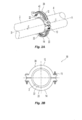
[00010] A figura 1A é um diagrama esquemático em perspectiva de um arranjo de acoplamento preferido.[00010] Figure 1A is a schematic diagram in perspective of a preferred coupling arrangement.
[00011] A figura 1B é uma vista de extremidade do arranjo de acoplamento da figura 1A.[00011] Figure 1B is an end view of the coupling arrangement of figure 1A.
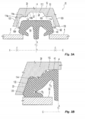
[00012] A figura 2A é um diagrama esquemático em perspectiva de outro arranjo de acoplamento preferido.[00012] Figure 2A is a schematic diagram in perspective of another preferred coupling arrangement.
[00013] A figura 2B é uma vista de extremidade do arranjo de acoplamento da figura 2A.[00013] Figure 2B is an end view of the coupling arrangement of figure 2A.
[00014] A figura. 3A é uma vista em seção transversal parcial de um arranjo de acoplamento preferido em uma configuração não comprimida.[00014] The figure. 3A is a partial cross-sectional view of a preferred coupling arrangement in an uncompressed configuration.
[00015] A figura 3B é o arranjo de acoplamento da figura 3A em uma configuração comprimida.[00015] Figure 3B is the coupling arrangement of figure 3A in a compressed configuration.
[00016] A figura 4A é um componente de alojamento preferido para uso nos arranjos das figuras 1A-1B e das figuras 2A-2B.A figura 4B é outro componente de alojamento preferido para uso nos arranjos das figuras 1A-1B e figuras 2A-2B.[00016] Figure 4A is a preferred housing component for use in the arrangements of figures 1A-1B and figures 2A-2B. Figure 4B is another preferred housing component for use in the arrangements of figures 1A-1B and figures 2A- 2B.
[00017] A figura 5A é uma gaxeta preferida para uso com o componente de alojamento da figura 4A.[00017] Figure 5A is a preferred gasket for use with the housing component of figure 4A.
[00018] A figura 5B é uma gaxeta preferida para uso com a o componente de alojamento da figura 4B.[00018] Figure 5B is a preferred gasket for use with the housing component of figure 4B.
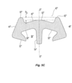
[00019] A figura 5C é outra gaxeta preferida para uso com o arranjo das figuras 3A-3B.[00019] Figure 5C is another preferred gasket for use with the arrangement of figures 3A-3B.
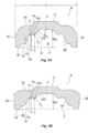
[00020] A figura 6A é uma vista em seção transversal parcial de outra modalidade de um arranjo de acoplamento.[00020] Figure 6A is a partial cross-sectional view of another embodiment of a coupling arrangement.
[00021] A figura 6B é uma vista em seção transversal parcial de outra modalidade de um arranjo de acoplamento.[00021] Figure 6B is a partial cross-sectional view of another embodiment of a coupling arrangement.
[00022] É mostrada nas figuras 1A e 1B e as figuras 2A e 2B a formação de um tubo preferido ou montagem de junta de tubo usando um arranjo de acoplamento preferido 10. Na montagem de junta preferida, os segmentos de tubo ou de extremidade de tubulação 2, 4 são alinhados axialmente ao longo de um eixo do tubo X-X e uma gaxeta 40 está disposta sobre os segmentos de extremidade 2, 4. O tubo ou tubulação pode ser de cobre, aço ou outro material tubular para formar uma montagem de junta. Um alojamento de acoplamento preferido tendo pelo menos dois componentes de alojamento 12, 14 está engatado sobre a gaxeta 40. Os componentes de alojamento podem ser componentes separados, como visto na figura 1A ou, alternativamente, podem ser pré-montados em um arranjo acoplado, por exemplo, no dispositivo do tipo articulado mostrado nas figuras 2A e 2B. Um acoplamento articulado preferido para uso no arranjo de acoplamento é mostrado e descrito no Pedido Provisório US no 61/255, 351, depositado em 27 de outubro de 2009, intitulado "Sistemas e Métodos de Acoplamentos de Articulação", e que é incorporado por referência na sua totalidade. Os componentes de alojamento podem ser idênticos em estrutura, de modo a refletir uma ao outro sobre X-X ou alternativamente podem ser configurados de modo diferente, contanto que sejam configurados para engatar ou alinhar um com um outro e formar o alojamento de acoplamento completo sobre a gaxeta 40. Além o mais, o alojamento de acoplamento pode ser formado por mais de dois componentes, com a condição de que os componentes possam ser acoplados juntos para engatar eficazmente a gaxeta 40 para formar a junta de tubo, como visto, por exemplo, na Patente US no 6.139.069 que é incorporada ao presente documento por referência na sua totalidade.[00022] Figures 1A and 1B and figures 2A and 2B show the formation of a preferred pipe or pipe joint assembly using a preferred
[00023] Geralmente, cada um dos componentes de alojamento 12, 14 tem uma primeira extremidade 16, uma segunda extremidade 18 com um segmento preferivelmente arqueado 20 estendendo-se entre a primeira e segunda extremidades 16, 18 para engate com a gaxeta 40. Dependendo do número de componentes que formam o alojamento, os segmentos podem ser semicirculares, quarto de círculo ou definir outro comprimento de arco. As extremidades 16, 18 são de preferência configuradas como extensões de amortecedor de parafuso tendo furos de passagem nos quais os fixadores 19 estão dispostos para segurar e/ou acoplar os componentes de alojamento 12, 14 um ao outro. Os segmentos de engate de tubos 20 incluem ainda uma superfície interna 22 que define uma cavidade de gaxeta 24 para engatar e alojar a gaxeta 40.[00023] Generally, each of the
[00024] A fim de completar a formação da junta de tubos, os componentes de alojamento 12, 14 estão dispostos sobre a gaxeta 40. Para formar a vedação estanque a fluidos, os fixadores são apertados de modo a retirar os alojamentos 12, 14 juntos. Como os componentes 12, 14 são retirados juntos, a superfície interna 22 dos componentes comprimem a gaxeta 40 para formar uma vedação estanque a fluidos. A montagem completa define o eixo central C-C do arranjo de acoplamento 10, que é coaxialmente alinhado com o eixo de tubo X-X.[00024] In order to complete the formation of the pipe joint, the
[00025] São mostradas respectivamente na figura 3A e figura 3B vistas não comprimidas e comprimidas da montagem de junta de tubos preferida para ilustrar o engate de contato de superfície entre a superfície interna 22 do componente de alojamento 12 e a gaxeta 40. De preferência, o arranjo de acoplamento 10 é simétrico sobre um eixo mediano A-A que se estende perpendicularmente ao eixo central C-C do acoplamento 10. Alternativamente, o arranjo pode ser assimétrico, por exemplo, como é o caso de um arranjo de junta de tubo reduzido. O alojamento 12 preferido e sua superfície interna 22 define um perfil de superfície preferido 106. O perfil de superfície 106 inclui de preferência uma porção que se afila para dentro na direção do eixo mediano A-A para definir um diâmetro interior decrescente e formar um ou mais entalhes 30 dispostos em torno do eixo mediano A-A. Os entalhes 30 podem, alternativamente, ser definidos por triângulos formados sobre a superfície interna 22 sobre o eixo mediano A-A em que os vértices estendem-se radialmente para dentro da cavidade 24. Com referência à vista comprimida da figura 3B, a superfície interna 22 e do seu perfil 106 engatam a superfície periférica da gaxeta 40 aplicando uma força de compressão radial. O entalhe 30 e a sua superfície afilada incluem um ponto P0 que define um diâmetro interno da superfície interna afilada 22 que é menor do que o diâmetro da gaxeta 40 no local onde o ponto P0 faz contato. Consequentemente, na formação de uma vedação estanque a fluidos na junta de tubos com o arranjo de acoplamento 10, o entalhe 30 deforma a gaxeta 40 no ponto P0 de contato, de preferência radialmente na direção do eixo o C-C Devido a um canal interno 58 da gaxeta 40 , a porção lateral da gaxeta 40 dobra em um ponto P1 ao longo do perfil do canal 58 para formar o engate vedado com a superfície externa do segmento de tubo 2, 4 e a porção lateral da gaxeta 40 se move-se lateralmente contra a superfície interna 22 do alojamento 12. A pressão do fluido interna na junta de tubos pode mover uma porção central da gaxeta 40 radialmente para fora, para contatar a superfície interna 22 do alojamento na parte mais profunda da cavidade da gaxeta 24 para estabilizar ainda mais a posição da gaxeta 40 dentro da cavidade 24. Para o arranjo de acoplamento 10 preferido, a formação do entalhe 30 de preferência localiza o ponto P0 de contato medianamente para dentro do ponto P1 de flexão da gaxeta com relação ao eixo mediano A-A de modo que o ponto de contato P0 é mediano do ponto de flexão P1. Além do mais, o ponto P0 está preferivelmente localizado de modo a não minimizar ou negar a pressão de fluido interno para mover a gaxeta radialmente para dentro contra o alojamento de acoplamento.[00025] Uncompressed and compressed views of the preferred pipe joint assembly are shown respectively in figure 3A and figure 3B to illustrate the surface contact engagement between the
[00026] A figura 3A mostra uma vista em seção transversal geral do componente de alojamento 12 preferido tendo uma primeira face lateral 100 e um segundo face lateral 102, que definem entre elas o eixo mediano A-A do componente de alojamento 12. Estendendo-se entre a primeira e segunda faces laterais está o corpo do componente 12 que inclui um perfil de superfície periférica 104 (visto nas Figuras 4A e 4B como 104’ e 104") e um perfil de superfície interna 106 preferido da superfície interna 22. A superfície interna 106 inclui de preferência para cada lado do eixo mediano A-A, uma porção de engate de tubos 108 (mostrada nas figuras 4A e 4B como 108’e 108"), uma porção de parede lateral 110, uma porção de parede traseira 112, e uma porção de transição 114 estendendo-se entre uma as porções de parede lateral e de parede traseira 110, 112. A porção de engate de tubos 108 engata diretamente na superfície externa do segmento de tubos na montagem de junta de tubos e, preferivelmente, estende-se substancialmente linearmente paralela ao eixo central C-C do arranjo de acoplamento 10. A porção de parede lateral 110 é contígua com a porção de engate de tubos 108 para definir uma superfície para engate com a parede lateral da gaxeta 40 na montagem de junta. A porção de parede lateral 110 também é,de preferência, substancialmente linear definindo um ângulo preferivelmente obtuso α com a linha paralela ao eixo A-A. Mais preferivelmente formada entre a porção de engate de tubos 108 e a porção de parede lateral 110 está uma transição de superfície 109, que pode tanto ser arredondada definindo um raio de curvatura ou mais preferivelmente define uma transição de etapas entre a porção de engate de tubos 108 e a porção de parede lateral 110.[00026] Figure 3A shows a general cross-sectional view of the
[00027] A porção da parede traseira 112 do perfil de superfície interna 106 de preferência define a porção da superfície interna do alojamento interior 22, que suporta uma porção mediana da gaxeta 40 e, mais preferivelmente, definem a porção mais profunda da cavidade de gaxeta 24. Alternativamente, uma parede traseira 112 pode estar localizada a uma profundidade equivalente ao ponto de contato P0 do entalhe 30, ou a uma profundidade mais rasa do que P0, mas mais profunda do que o ponto PI ponto da gaxeta. Na modalidade preferida 12, a porção de parede traseira 112 do perfil de superfície interna 106 é substancialmente linear ou planar estendendo-se em uma direção paralela ao eixo central C-C do acoplamento 10. Alternativamente, a porção de parede traseira 112 pode ser um ponto de contato mais profundo único da superfície interna104 para engate com a gaxeta de 40. Além disso, em alternativa, a porção de parede traseira 112 pode definir um segmento da superfície interna 106 que define múltiplos pontos de contato para a gaxeta 40, no qual os múltiplos pontos de contato definem o ponto mais profundo da cavidade de gaxeta que engata a gaxeta 40.[00027] The
[00028] Estendendo-se contiguamente entre a porção de parede traseira 112 e a porção de parede lateral 110 do perfil de superfície interna 106 está a porção de transição 114. A porção de transição 114 inclui de preferência uma primeira extremidade arredondada 114a que define um raio de curvatura contígua com a porção de parede lateral 110, e uma segunda extremidade arredondada 114b que define um raio de curvatura contígua com a porção de parede traseira 112. Alternativamente, as extremidades 114a, 114b podem ser mais de etapa de tipo de transição. Entre as extremidades 114a, 114b a porção de transição 114, de preferência, define o entalhe 30 da superfície interna 22 descrita acima. Preferivelmente, porção de transição 114 define um segmento 114c do perfil de superfície interna 106 tendo um declive negativo, significando que na direção a partir de uma face lateral 100, 102 para o eixo mediano A-A, a profundidade da cavidade de gaxeta 24 diminui ao longo do comprimento do segmento em declive 14c na direção lateral para mediana. Consequentemente, o segmento 114c define um afunilamento estreitando o perfil de superfície interna 106 para o acoplamento do componente de alojamento 12 na direção lateral para mediana de modo a definir um diâmetro interno decrescente do alojamento sobre o segmento 114c. O segmento 114c é de preferência linear ou, alternativamente, pode ser definido por um perfil ondulante ou outro não-linear sobre seu comprimento contanto que o segmento defina um estreitamento de afunilamento em uma área da superfície interna 22 do componente de alojamento 12 que contata com a gaxeta 40. A porção de transição 114 do perfil de superfície interna 106 pode incluir uma combinação de segmentos lineares e não lineares contanto que a porção de transição 114 defina efetivamente um entalhe 30, como descrito acima.[00028] Extending contiguously between the
[00029] É mostrado na figura 4A um componente de alojamento 12’ preferido para um acoplamento 10’ nominal de 15,24 cm (seis polegadas). O componente tem uma primeira face lateral, 100' e uma segunda face lateral 102' espaçadas uma da outra para definir o eixo mediano A'-A’do componente de alojamento 12'. As faces laterais 100', 102' definem a largura W do acoplamento 10’ sobre o eixo mediano A'-A' em que a largura W de preferência está na faixa de cerca de 3,82 a cerca de 7,62 cm (1,5 a cerca de três polegadas) e é de aproximadamente 4,57 cm (1,8 polegadas). O componente de alojamento 12' inclui uma superfície periférica 104' que define a superfície externa da montagem de acoplamento 10'. O componente de alojamento 12' inclui ainda um perfil de superfície interna 106' para definir a cavidade da gaxeta 24' para alojar uma gaxeta 40. O perfil de superfície interna 106' é simétrico em torno do eixo mediano A'-A' e inclui na sua extremidade lateral da superfície de engate de tubos 108'. Estendendo-se medianamente, o perfil de superfície interna 106' inclui ainda a porção de parede lateral 110' com uma transição de etapa substancial 109’entre a porção de acoplamento de tubos 108' e a porção de parede lateral 110’. O segmento de parede lateral 110' é de preferência linear com uma declive positivo de modo que a profundidade da cavidade de gaxeta 24 aumenta na direção lateral para mediano sobre o comprimento do segmento de parede lateral 110'. O segmento de parede lateral de preferência ainda define um ângulo α’ de cerca de vinte graus (20°) com respeito a uma linha paralela ao eixo mediano A'-A'. Os segmentos de parede lateral 110’estão espaçados em torno do eixo mediano A'-A' para acomodar a espessura da gaxeta 40.[00029] A preferred housing component 12 'for a 15.24 cm (six inch) nominal 10' coupling is shown in figure 4A. The component has a first side face, 100 'and a second side face 102' spaced from one another to define the median axis A'-A 'of the housing component 12'. The side faces 100 ', 102' define the width W of the coupling 10 'on the median axis A'-A' where the width W is preferably in the range of about 3.82 to about 7.62 cm (1 , 5 to about three inches) and is approximately 4.57 cm (1.8 inches). The housing component 12 'includes a peripheral surface 104' that defines the outer surface of the coupling assembly 10 '. The housing component 12 'further includes an inner surface profile 106' to define the gasket cavity 24 'to accommodate a
[00030] A porção de parede traseira do perfil de superfície interna 106' do componente de alojamento 12’ de preferência define o Hmax de maior profundidade da cavidade gaxeta 24', que é de preferência cerca de 1,27 cm (0,5 pol.) a partir de uma linha de base B localizada no plano das superfícies de engate de tubos 108'. Na montagem de acoplamento completa 10, a porção de parede traseira 112 define o diâmetro interno máximo do acoplamento 10' que é de preferência cerca de 17,78 cm (7 pol.). A porção de parede traseira 112 é de preferência linear estendendo-se paralelamente ao eixo de acoplamento C-C para definir a largura mínima da cavidade 24.[00030] The rear wall portion of the inner surface profile 106 'of the housing component 12' preferably defines the deepest Hmax of the gasket cavity 24 ', which is preferably about 1.27 cm (0.5 in.) .) from a baseline B located on the plane of the pipe engaging surfaces 108 '. In the
[00031] Estendendo-se entre a porção de parede lateral 110' e a parte de parede traseira 112' está a porção de transição 114’. A porção de transição 114’ de preferência inclui uma primeira porção arredondada 114'a contígua com a porção de parede lateral 110' e uma segunda porção arredondada 114'b contígua com a porção de parede traseira 112’. A porção de transição 114’ inclui um segmento de preferência linear 114'c que define uma porção estreitamente de afunilamento da superfície interna 22' na direção lateral para mediana entre os pontos de P'1 e P'2 para definir um entalhe 30’ e uma diâmetro interno decrescente sobre o segmento 114c’. O ponto P'1 está de preferência localizado na extremidade da porção de parede lateral 110’ e a porção arredondada concavamente 114'a tendo um raio de curvatura preferido abaixo de 0,254 cm (0,1 polegada) e de preferência cerca de 0,152 cm (0,06 polegada). O ponto P2 está localizado na extremidade do segmento linear 114'c e contíguo com uma porção arredondada convexamente 114'd tendo um raio de curvatura de 0,254 cm (0,1 polegada) e preferivelmente cerca de 0,152 cm (0,06 polegada). Além do mais, P1 está de preferência localizado a uma profundidade da cavidade h1 medida a partir da linha de base B, e P2 está preferivelmente localizado a uma profundidade da cavidade h2 a partir da linha de base B em que h2 é menor do que h1.[00031] Extending between the side wall portion 110 'and the rear wall portion 112' is the transition portion 114 '. The transition portion 114 'preferably includes a first rounded portion 114'a contiguous with the side wall portion 110' and a second rounded portion 114'b contiguous with the rear wall portion 112 '. The transition portion 114 'includes a preferably linear segment 114'c that defines a narrowly tapering portion of the inner surface 22' in the lateral to median direction between the points of P'1 and P'2 to define a notch 30 'and a decreasing internal diameter over
[00032] É mostrado na figura 4B um componente de alojamento 12" preferido para um acoplamento 10".nominal de 5,08 cm (2 polegadas). O componente tem uma primeira face lateral 100" e uma segunda face lateral 102" espaçadas uma da outra para definir o eixo mediano A"-A" do componente de alojamento 12". As faces laterais 100", 102" do componente de alojamento 12, 102" definem a largura W" do acoplamento 10" em torno do eixo mediano A"-A", em que a largura W" está de preferência na faixa de cerca de 3,81 cm a cerca de 5,08 cm (cerca de 1,5 a cerca de 2 polegadas) e é de aproximadamente 4,572 cm (1,8 polegada). O componente de alojamento 12" inclui uma superfície periférica 104", que define a superfície externa da montagem de acoplamento 10". O componente de alojamento 12" inclui ainda uma superfície interna 106" para definir uma cavidade de gaxeta 24" para alojar uma gaxeta 40. A superfície preferida interior 106" é simétrica em torno do eixo mediano A"-A"e inclui na face lateral do tubo a superfície de engate de tubos 108". Estendendo-se medianamente, a superfície interna 106" inclui ainda a porção de parede lateral 110" com substancialmente uma transição de etapas 109" entre a porção de engate de tubos 108" e a porção de parede lateral 110". A porção de parede lateral 110" geralmente define um declive positivo de modo que o profundidade da cavidade de vedação 24" aumenta na direção lateral para mediana sobre o comprimento do segmento de parede lateral 110' para definir um ângulo preferido α’ de cerca de trinta graus e, preferivelmente, cerca de vinte e sete graus (27°) com respeito a uma linha paralela ao eixo mediano A"-A" Os segmentos de parede lateral 110" são espaçados em torno do eixo mediano A"-A" para acomodar a espessura da gaxeta 40.[00032] A
[00033] A porção de parede traseira da superfície interna 106" do componente de alojamento 12’ define um Hmax’ mais profundo da cavidade da gaxeta, que é preferivelmente cerca de 1,27 cm (0,5 polegadas) a partir de uma linha de base B" que está localizada no plano das superfícies de acoplamentos de tubos 108". Na montagem de acoplamento completo 10", a porção de parede traseira 112" define o diâmetro interno máximo do acoplamento 10", que é preferivelmente cerca de 7,62 cm (três polegadas). A porção de parede traseira 112 é de preferência linear tendo um comprimento estendendo-se paralelo ao eixo de acoplamento C-C para definir uma largura mínima da cavidade 24. Estendendo-se entre a porção de parede lateral 110" e a porção de parede traseira 112" está a porção de transição 114". A porção de transição 114" preferivelmente inclui uma primeira porção arredondada 114"a contígua com a porção de parede lateral 110" e uma segunda parte arredondada 114"b contígua com a porção de parede traseira 112".[00033] The rear wall portion of the
[00034] A porção de transição 114" inclui um segmento de preferência linear 114"c tendo um declive negativo que define uma porção estreitamente de afunilamento da superfície interna 106" na direção lateral para mediana entre os pontos P"1 e P"2 para definir o entalhe 30"e um diâmetro interno decrescente sobre o segmento 114c". O ponto P"1 está de preferência localizado na extremidade da porção de parede lateral 110’ e a porção concavamente arredondada 114"a tendo um raio de curvatura abaixo de 0,254 cm (0,1 polegadas) e de preferência cerca de 0,152 cm (0,06 polegada). O ponto P2 está localizado na extremidade do segmento 114'c contígua com uma porção convexamente arredondada 114'd tendo um raio de curvatura abaixo de 0,254 cm (0,1 polegadas) e de preferência cerca de 0,152 cm (0,06 polegadas). Além do mais, P"1 está de preferência localizado a uma profundidade de cavidade h1 medida a partir da linha de base B" e P"2 está de preferência localizado a uma profundidade de cavidade h2 a partir da linha de base B" na qual h2 é menor do que h1.[00034] The
[00035] Como observado anteriormente, os entalhes 30 definidos ao longo das superfícies internas dos componentes do alojamento 12 descritos acima são configurados para aplicar uma força de compressão radialmente para dentro contra a gaxeta 40 para melhorar e/ou manter a vedação estanque a fluidos da gaxeta 40. Em particular, os entalhes 30 definem uma superfície cônica ou cunha ao longo da superfície interna 22 do componente de alojamento de acoplamento 12 para aplicar uma força à superfície periférica da gaxeta em uma direção radialmente para dentro em direção ao centro do acoplamento C-C e lateralmente para fora na direção das porções de parede lateral 110 do alojamento 12. As gaxetas 40 preferivelmente para uso com os alojamentos de acoplamento descritos no presente documento são corpos anelares ou do tipo de anel definindo um eixo central G-G da gaxeta para alinhamento com o acoplamento do eixo C-C.[00035] As noted earlier, the
[00036] É mostrada na figura 5A uma gaxeta 40 nominal preferida de 15,24 cm (seis polegadas) para uso com o acoplamento 10’ nominal preferido de 15,24 cm (seis polegadas) da figura 4A. O corpo anular 42 da gaxeta tem uma parede lateral 44 para receber o primeiro segmento de tubo 2, uma segunda parede lateral 46 para receber o segundo segmento de tubo 14. A segunda parede lateral 46 é espaçada da primeira parede 44 para definir um eixo mediano B-B entre as mesmas estendendo-se perpendicular ao eixo central G-G da gaxeta. O corpo anular 42 inclui uma superfície periférica externa 48 e uma superfície interna 50 espaçadas radialmente a partir do eixo central G - G da gaxeta. Cada uma das superfícies periférica e interna 48, 50 é de preferência simétrica em torno do eixo mediano B-B da gaxeta e é, além do mais, preferivelmente contígua com as paredes laterais 44, 46 da gaxeta tendo um canto arredondado definindo a transição entre as paredes laterais 44, 46 e as superfícies periférica e interna 48, 50 da gaxeta.[00036] A preferred nominal 15.24 cm (six inch)
[00037] Em seção transversal, a superfície interna 50 define um par de superfícies de vedação de rebordo 52, que estão dispostas de preferência equilateralmente sobre o eixo mediano B-B. As superfícies dos rebordos de vedação 52 engatam diretamente a superfície externa dos segmentos de tubo para formar uma vedação estanque a fluidos quando da aplicação de uma força de compressão suficiente sobre a gaxeta 40. Os rebordos de vedação 52 definem um perfil que, no estado não comprimido da gaxeta 40, define um ângulo obtuso com uma linha paralela ao eixo mediano B-B o perfil dos rebordos de vedação pode incluir porções lineares, porções arredondadas e/ou uma combinação das mesmas. De preferência, formado com e dependendo da superfície interna 50 ao longo do eixo mediano é uma porção de perna central 54. A perna central age como um tampão e divisor entre as extremidades dos segmentos de tubo que são unidos como visto, por exemplo, nas figuras 3A e 3B. O perfil da perna central 54 preferida afunila-se estreitamente na direção axial ao longo do eixo mediano A’-A’ variando em espessura sobre seu comprimento axial de cerca de 0,254 cm a cerca de 0,508 cm (0,1 polegada a cerca de 0,2 polegada).[00037] In cross section, the
[00038] A superfície interna 50 da gaxeta 40’ inclui ainda um segmento de transição 56 que conecta a superfície de rebordo de vedação 52 à perna central 54. O segmento de transição 56 define uma cavidade ou canal 58 entre a superfície do rebordo de vedação e da perna central 54. A cavidade 58 definida pelo segmento de transição 56 fornece um vazio no qual o corpo da gaxeta 42 pode dobrar sobre si mesmo sob as forças de compressão dos componentes de alojamento 12, 14 do acoplamento 10 e a pressão do fluido transportado nos segmentos de tubo e através da junta de tubos. O segmento de transição 56 inclui preferivelmente uma combinação de porções arredondadas e porções lineares para conectar a superfície de rebordo de vedação 52 à perna central 54.[00038] The
[00039] Na modalidade preferida da figura 5A, o segmento de transição 56 inclui uma primeira porção 56a que de preferência inicia com uma primeira porção arredondada convexamente R1 que é contígua com um segmento linear que se estende lateralmente para a parede lateral 44, 46 e perifericamente em direção à superfície periférica 48 para uma segunda porção arredondada R2 sobre a qual o corpo da gaxeta 42 dobra. O segmento de transição 56 ainda inclui de preferência uma segunda porção 56b que é de preferência inicialmente uma linha de segmento de linha contíguo com a segunda porção arredondada R2 e estende-se medianamente em direção ao eixo mediano A-A e à superfície periférica 48 da gaxeta para uma terceira porção arredondada R3 contígua com a perna central 54. O perfil geométrico preferido e, em particular, o segmento de declive positivo 56 fornece um canal de vedação desejável 58 em que a profundidade do canal 58, como medida a partir de uma linha paralela ao eixo C-C da gaxeta, aumenta na direção lateral para mediana. Consequentemente, o corpo 42 da gaxeta 40 diminui na sua espessura radial para uma porção do corpo 42 ao longo da direção lateral para mediana.[00039] In the preferred embodiment of figure 5A, the
[00040] Para a gaxeta 40 preferida da figura 5A as superfícies de paredes laterais angulares 44, 46 são espaçadas para definir uma espessura de gaxeta, que está na faixa de uma espessura mínima na superfície periférica de cerca de 2,286 cm (0,9 polegada) a uma espessura máxima de toda a gaxeta 40 de cerca de 2,794 cm (1,1 polegada). As gaxetas preferidas são de preferência dimensionadas para deslizar sobre as extremidades dos segmentos de tubo com pelo menos uma porção da superfície de rebordo de vedação 52 formando uma superfície de contato com a superfície externa dos segmentos de tubo e da perna central 54 engatar a superfície de extremidade do segmento de tubo. Para um segmento de tubo nominal de 15,24 cm (6 polegadas), a superfície periférica 48 define um diâmetro externo preferido Dmax para a gaxeta 40 para ser de cerca de 17,78 cm (sete polegadas). A perna central 54 define um Dmin de diâmetro interno mínimo preferido da gaxeta de cerca de 14,605 cm (5,75 polegadas), e os rebordos de vedação 52 definem um diâmetro D preferido, na sua extremidade mais mediana de cerca de 15,24 cm (seis polegadas). A largura da perna central 54, de preferência afunila na direção radial em direção ao eixo G-G da gaxeta.[00040] For the
[00041] Para a superfície interna preferida 50 da gaxeta nominal de (15,24 cm (6 polegadas), a terceira porção arredondada R3 inclui um raio preferido de de 0,152 (0,06 polegada) e está localizada mais próxima do eixo mediano B-B do que R2. A segunda porção arredondada R2 inclui um raio preferido de cerca de (0,076 cm (0,03 polegadas) e está localizada mais próximo do eixo G-G da gaxeta do que a R3.[00041] For the preferred
[00042] É mostrada na figura 5B outra gaxeta preferida 40’, que incorporam características semelhantes das modalidades anteriores, mas é de preferência dimensionada e configurada para segmentos de tubo nominais de 5,08 cm (duas polegadas). Em particular, a superfície periférica gaxeta 40’ define um diâmetro Dmax de cerca de 7,62 cm (três polegadas), a perna central 54 define um diâmetro mínimo preferido Dmin da gaxeta de levemente 5,08 cm (duas polegadas), com os rebordos de vedação 52 definindo um diâmetro D preferido em sua extremidade mais mediana de cerca de 5,08 cm (duas polegadas). Para a superfície interna preferida 50’ da gaxeta nominal de 15,24 cm (seis polegadas), a terceira porção arredondada R3' inclui um raio preferido de 0,15 cm (0,06 polegada) e está localizada mais próxima do eixo mediano B’- B’ do que R2'. A segunda porção arredondada R2’ inclui um raio preferido de menos de 0,254 cm (0,1 polegada) e está localizada mais próxima do eixo G-G da gaxeta do que R3’.[00042] Another preferred gasket 40 'is shown in figure 5B, which incorporates similar characteristics of the previous modalities, but is preferably sized and configured for nominal 5.08 cm (two inch) pipe segments. In particular, the peripheral gasket surface 40 'defines a diameter Dmax of about 7.62 cm (three inches), the
[00043] Com referência novamente à figura 3B e ao estado comprimido do arranjo de acoplamento preferido 10, o ponto baixo P0 do entalhe 30 do componente de alojamento está localizado medianamente interno do P1 sobre o segundo raio R2 preferido da gaxeta 40 sobre o qual a gaxeta dobra. Esta configuração preferida proporciona um contato de superfície entre a superfície interna 22 do componente de alojamento 12 e a superfície periférica 48 da gaxeta 40, que provê uma força que tem um componente horizontal na direção lateral para melhorar ou manter o contato entre a porção de parede lateral 110 do componente de alojamento 12 e a parede lateral 44, 46 da gaxeta 40, a fim de manter ou aumentar o engate vedado entre a gaxeta e a superfície externa dos segmentos de tubo.[00043] With reference again to figure 3B and the compressed state of the
[00044] Para cada uma das gaxetas 40’, 40" preferidas, a superfície periférica 48 define um perfil que é substancialmente planar estendendo-se paralelo ao eixo C-C central da gaxeta. Em outra modalidade alternativa da gaxeta 40'", mostrada na figura 5C, a superfície periférica 48’‘‘ define um perfil que é não li near. Em particular, a superfície periférica 48"' define preferivelmente um perfil que é simétrico em torno do eixo mediano B’"-B"’ da gaxeta com duas porções de extremidade aumentada 60’’’ e uma porção central 62’‘‘ localizada radialmente para dentro das porções de extremidade arredondadas 60"' Na modalidade da figura 5C, a porção central 62’‘‘ é preferivelmente arqueada e simétrica em torno do eixo mediano B'"-.B’". As porções de extremidade 60’" proporcionam um perfil de transição entre as paredes laterais de vedação 44’’’, 46’’’ e a porção central 62"' da superfície periférica. O perfil da porção de extremidade 60’‘‘ pode ser definido pelos segmentos arredondados, segmentos substancialmente lineares ou uma combinação de ambos. As superfícies das porções de extremidade 60'", sozinha ou em combinação com a porção central 62’‘‘, definem uma superfície da gaxeta que pode engatar a superfície cônica preferida do entalhe 30 nos componentes de alojamento descritos no presente documento para prover uma força normal dirigida lateralmente na direção da porção de parede lateral do alojamento da gaxeta. O diâmetro da gaxeta 40’‘‘de preferência varia de uma face lateral da gaxeta para a próxima. De preferência, as porções de extremidade arredondadas 60’‘‘ definem um diâmetro maior da gaxeta 40"' do que a porção central 62’’’, e mais preferivelmente as porções de extremidade 60"' definem o diâmetro máximo da gaxeta 40’‘‘ com o centro do a porção arqueada 62’‘‘ definindo uma percentagem do diâmetro máximo da gaxeta na faixa de cerca de 90 por cento a cerca de 99 por cento (9099%). Consequentemente, os diâmetros da gaxeta definidos nas porções de extremidade 60’’’ e na porção central 62"' podem definir entre um e outro um diferencial de percentual no perfil de diâmetro da gaxeta que está na faixa de entre um a cerca de dez por cento (110%). Alternativamente, cada uma das porções de extremidade 60’‘‘ e porção central ‘"' podem definir uma perpendicular ao eixo mediano B’"-B'" que ainda define uma diferencial radial RD ao longo do eixo mediano B’‘‘-B’’’ que pode ser de cerca de 0,254 cm (0,1 polegada) ou menos.[00044] For each of the preferred 40 ', 40 "gaskets, the peripheral surface 48 defines a profile that is substantially planar extending parallel to the central CC axis of the gasket. In another alternative embodiment of the 40'" gasket, shown in the figure 5C, the peripheral surface 48 '' 'defines a profile that is nonlinear. In particular, the peripheral surface 48 "'preferably defines a profile that is symmetrical about the median axis B'" - B "'of the gasket with two enlarged end portions 60' '' and a central portion 62 '' 'located radially into the
[00045] Em vista das descrições acima tanto das gaxetas preferidas como dos alojamentos, os arranjos de acoplamentos de tubo alternativos são possíveis. Por exemplo, como mostrado nas figuras 6A e 6B, são ilustrações de seção transversal esquemática de arranjos de acoplamentos de tubos que usam uma modalidade alternativa da gaxeta 40’’’. Mais especificamente, é mostrada na figura 6A uma modalidade alternativa da gaxeta 40’’’, a superfície periférica 48’‘‘ define um perfil tendo duas porções de extremidade aumentada 60’‘‘ com uma porção central substancialmente linear 62"' entre as mesmas que funciona substancialmente paralela ao eixo G-G da gaxeta e/ou ao acoplamento eixo X-.X No arranjo da Figura 6A, um alojamento 12 é provido tendo uma superfície interna 22 com um perfil 106 que substancialmente espelha a superfície periférica 48’‘‘ de uma forma substancialmente em cauda de andorinha. Mais especificamente, a superfície interna 22 tem um perfil de superfície interna 106 em que a porção de parede traseira 112 está preferivelmente na mesma profundidade de cavidade e formada contiguamente formada com os entalhes 30 de modo a definir uma superfície centralizada que engata na porção substancialmente linear central 62’‘‘ da gaxeta 40’‘‘ no arranjo de acoplamento montado. A porção de parede traseira 112 engata preferivelmente substancialmente ao longo de seu comprimento. O perfil de superfície interna 106 resulta em um par de recessos laterais simetricamente dispostos sobre a porção de parede traseira 112 para alojar as porções de extremidade arredondadas 60’’’. Na modalidade da figura 6A, os entalhes 30 paralelos e/ou engatam os segmentos de superfície substancialmente lineares das porções de extremidade 60’‘‘ de modo a proverr a força na direção lateral para as paredes laterais do segmento alojamento 12.[00045] In view of the above descriptions of both the preferred gaskets and the housings, alternative pipe coupling arrangements are possible. For example, as shown in figures 6A and 6B, they are schematic cross-sectional illustrations of pipe coupling arrangements using an alternative 40 ’’ ’gasket embodiment. More specifically, an alternative embodiment of the 40 '' gasket is shown in figure 6A, the peripheral surface 48 '' 'defines a profile having two enlarged end portions 60' '' with a substantially linear central portion 62 '' between them which functions substantially parallel to the GG axis of the gasket and / or the X-X axis coupling. In the arrangement of Figure 6A, a
[00046] As gaxetas 40, 40’, 40'" preferidas descritas no presente documento podem ser usadas com os componentes de alojamento que não incluem entalhes 30. Assim, as gaxetas preferidas 40, 40’, 40'" podem ser usadas com alojamentos conhecidos. O inventor descobriu uma faixa de RD diferencial radial preferida, como definido entre as porções de extremidade aumentada 60’’’ e porção central 62"' da gaxeta 40’‘‘ para a qual um alojamento tendo um entalhe 30 é o preferido. Para uma diferencial radial RD maior do que 0,152 cm (0,06 polegada) um entalhe é desejável para prover a força normal tendo um componente dirigido lateralmente. Para um diferencial radial RD de cerca de 0,152 cm (0,06 polegada) ou menos, o arranjo de acoplamento pode empregar um alojamento sem um entalhe ao longo da superfície interna. Por exemplo, é mostrada na figura 6B a gaxeta 40’‘‘ com um alojamento 12 em que a superfície interna 22 não tem um entalhe 30. As porções de extremidade aumentada são configuradas para engatar a superfície interna do alojamento 22 de modo que na configuração de acoplamento montado, as paredes laterais 44’’’, 46’’' da gaxeta 40’‘‘ são dirigidas lateralmente e a porção central 62"' é dirigida radialmente para fora na direção da parede traseira do alojamento. Na gaxeta 40’’’, o perfil de cada porção de extremidade aumentada 60"' é de preferência definido por um segmento linear para engatar a parede traseira do alojamento com porções preferivelmente arredondadas em cada lado, que são respectivamente contíguas com a porção central 48’" e as paredes laterais da gaxeta. A porção de extremidade aumentada 60’’’ e a porção central 48"' definem preferivelmente um diferencial radial RD de cerca de 0,152 cm (0,06 polegada).[00046]
[00047] Como notado acima, o segmento de transição 56’‘‘ ao longo da superfície interna 50"' da gaxeta pode incluir uma combinação de porções arredondadas variadas e/ou porções lineares para conectar a superfície de rebordo de vedação 52 à perna central 54. Por exemplo, o segmento de transição 56’" pode consistir de dois ou mais segmentos arredondados 56a, 56b, 56c, 56d estendendo-se a partir da superfície de rebordo de vedação 52"' para a perna central 54’‘‘ de modo que o canal 58" está substancialmente na forma de queda com rasgamento. Alternativamente, o segmento de transição 56’‘‘ pode incluir um ou mais segmentos lineares como pode ser visto, por exemplo, nas figuras 6A e 6B. Além disso, o segmento de transição 56'" pode ser configurado de modo a prover uma espessura radial média desejada da gaxeta 40’‘‘ de modo a manter uma resistência ou resiliência desejada na gaxeta 40’’’. Consequentemente, o segmento de transição 56’’’ e o canal 58"' podem ser configurados de tal modo que a porção central 48’’’ e uma tangencial fora da porção mais radialmente para fora do canal 58"' perpendicular ao eixo mediano definem uma espessura radial do gaxeta sendo cerca de 0,254 cm (0,1 polegada) a cerca de 0,444 cm (0,175 polegadas).[00047] As noted above, the transition segment 56 '' 'along the
[00048] Outros aspectos das gaxetas podem variar, como, por exemplo, é visto na figura 6B, a superfície de rebordo de vedação 52’‘‘ pode incluir uma combinação de segmentos arredondados e/ou lineares para definir uma série de pontos de transição 52a'", 52b’", 52c'", e 52d’’’. A transição 52d'", de preferência, define um primeiro diâmetro interno da gaxeta que é maior do que o diâmetro nominal do tubo a ser unido. A transição 52c’’’ e 52b’’’ definem de preferência, respectivamente, o diâmetro de tubo máximo e mínimo para o diâmetro do tubo nominal determinado. O ponto de transição mais interno 52a’" está localizado radialmente em relação ao centro da gaxeta de modo a prover uma vedação suficiente sobre uma superfície de tubo externa que pode estar fora de fase para o tamanho do tubo nominal determinado. Os arranjos de acoplamento preferidos descritos no presente documento são preferivelmente usados para acoplar tubo ou tubulações e, em particular, tubulação de cobre ou de aço. Os arranjos de acoplamento das figuras 6A e 6B são bem adequados para unir tubos ou tubulações de aço tubo porque as superfícies de rebordo de vedação preferidas podem abordar eficazmente grandes variações dimensionais que podem ser experimentadas na junção de tubulação de aço no formato nominal. As gaxetas preferidas são de preferência dimensionadas para deslizar sobre as extremidades dos segmentos de tubo com pelo menos uma porção da superfície de rebordo de vedação 52’" formando uma superfície de contato com a superfície de extremidade dos segmentos de tubo e da perna central 54"' engatando a extremidade superfície do segmento de tubo. Para um segmento de tubo nominal de 10,16 cm (quatro polegadas) (4 pol.), a superfície periférica 48’‘‘ define um diâmetro externo máximo preferido para a gaxeta 40"' para ser de cerca de 13,97 cm (cinco polegadas e meia) e, mais preferivelmente de 13,716 cm (5,4 polegadas). A perna central 54’‘‘ define um diâmetro interno mínimo preferido da gaxeta de cerca de 10,16 cm (4 polegadas), e os rebordos de vedação 52"' definem um diâmetro preferido na sua extremidade mais mediana de cerca de 11,43 cm (quatro polegadas e meia) e, mais preferivelmente 11,176 cm (4,4 polegadas). A largura da perna central 54’‘‘ de preferência afunila na direção radial na direção do eixo da gaxeta. Para a gaxeta preferida 40"', as superfícies de parede lateral 44’’’, 46’’’ 46"' definem uma espessura média de cerca de 2,54 cm (uma polegada) e mais preferivelmente uma espessura mínima na superfície periférica de cerca de 2,286 cm (0,9 polegada) e uma espessura máxima da gaxeta 40’‘‘ de cerca de 3,048 cm (1,2 polegadas).[00048] Other aspects of the gaskets may vary, as, for example, it is seen in figure 6B, the sealing edge surface 52 '' 'may include a combination of rounded and / or linear segments to define a series of
[00049] São mostradas e descritas acima as modalidades preferidas de arranjos de acoplamento de 15,24 cm, 10,16 cm e 5,08 cm (seis, quatro e duas polegadas). As modalidades preferidas podem estar na faixa de tamanho de um acoplamento nominal de 2,54 cm a 30,48 cm (uma polegada a 12 polegadas). As configurações de gaxetas conhecidas podem ser usadas com os componentes de alojamento 10 preferidos descritos no presente documento. Por exemplo, como mostrado nas figuras 9A e 9B da Patente US no 61/7255.351, gaxetas no estilo padrão no formato "C ou de "três vedações", identificadas na página 12 em Tyco Fire & Suppression Products Publication IH-1000FP, intitulado "Grinnel® Grooved Fire Protection Installation Manual" (agosto de 2007) podem ser usadas nas montagens de acoplamento preferidas 10, 10’. Uma cópia da página 12 do manual de instalação é fornecida no Pedido de Patente US Provisória no 61/255.409, que é incorporada por referência na sua totalidade.[00049] The preferred embodiments of 15.24 cm, 10.16 cm and 5.08 cm (six, four and two inches) coupling arrangements are shown and described above. Preferred embodiments can be in the size range of a nominal coupling from 2.54 cm to 30.48 cm (one inch to 12 inches). The known gasket configurations can be used with the
[00050] Embora a presente invenção tenha sido divulgada com referência a certas modalidades, numerosas modificações, alterações, e trocas nas modalidades descritas são possíveis sem sair da esfera e escopo da presente invenção. Consequentemente, pretende-se que a presente invenção não seja limitada às modalidades descritas, mas que tenha o escopo total definido pela linguagem das seguintes reivindicações, e seus equivalentes.[00050] Although the present invention has been disclosed with reference to certain modalities, numerous modifications, changes, and changes in the described modalities are possible without departing from the scope and scope of the present invention. Consequently, it is intended that the present invention is not limited to the described modalities, but that it has the full scope defined by the language of the following claims, and their equivalents.
Claims (17)
um alojamento (12) tendo:
uma primeira face lateral (100) para receber um primeiro segmento de tubo (2);
uma segunda face lateral (102) para receber um segundo segmento de tubo (4), a segunda face lateral sendo espaçada a partir da primeira face lateral para definir um eixo mediano do alojamento; e
uma superfície interna (22) definindo uma cavidade, a superfície interna estendendo-se entre a primeira face lateral e a segunda face lateral de modo a ser cortada pelo eixo mediano e definir uma profundidade crescente da cavidade a partir da face lateral para o eixo mediano, a superfície interna definindo um perfil (106) entre uma das faces laterais e o eixo mediano, o perfil de superfície interna tendo:
uma porção de parede lateral (110);
uma porção de parede traseira (112); e
uma porção de transição (114) entre a porção de parede lateral e a porção de parede traseira, a porção de transição definindo um declive negativo na direção a partir de uma face lateral para o eixo mediano, a porção de transição define um entalhe (30) ao longo da superfície interna do alojamento, o entalhe (30) inclui uma primeira porção arredondada (114a), uma segunda porção arredondada (114b) com um segmento de linha reta (114c) estendendo-se entre a primeira e segunda porções arredondadas,
o segmento de linha reta definindo o declive negativo; e
uma gaxeta (40) disposta na cavidade de alojamento para formar uma vedação em torno de uma junta de tubo, a gaxeta (40) incluindo:
uma primeira face lateral (44);
uma segunda face lateral (46) espaçada a partir da primeira face lateral;
uma superfície periférica (48) e uma superfície interna (50), as superfícies periféricas e internas (48, 50) estendendo-se entre a primeira e segunda superfícies laterais, a gaxeta (40) sendo disposta no alojamento (12) de modo que as superfícies interna e periférica (48, 50) são cortadas pelo eixo mediano do alojamento (12), a superfície interna (50) definindo uma perna central (54) estendendo-se ao longo do eixo mediano, a superfície interna (50) definindo ainda um primeiro rebordo de vedação (52) e um segundo rebordo de vedação (52), o primeiro e segundo rebordos de vedação (52) estando dispostos em torno da perna central (54), de modo a definir um primeiro ponto de flexão (P1) e segmento de transição (56) da superfície interna (50) estendendo-se entre o primeiro rebordo de vedação (52) e da perna central (54) e um segundo ponto de flexão (P1) e segmento de transição (56) entre o segundo rebordo de vedação (52) e a perna central (54), o primeiro e segundo segmentos de transição (56) estendendo-se na direção do rebordo de vedação (52) na direção do eixo mediano e da superfície periférica (48) de modo a definir um declive positivo;
em que em uma configuração montada, o alojamento (12) engata a gaxeta, de modo a alocar o entalhe (30) do alojamento entre o ponto de flexão (P1) e o eixo mediano (A-A) e dobrar a gaxeta sobre o primeiro e segundo pontos de flexão (P1), de modo que pelo menos um dentre as primeira e segunda faces laterais (44, 46) da gaxeta são dirigidas lateralmente contra a porção de parede lateral (110) da superfície interna (22) do alojamento.Coupling (10) characterized by the fact that it comprises:
an accommodation (12) having:
a first side face (100) for receiving a first pipe segment (2);
a second side face (102) for receiving a second pipe segment (4), the second side face being spaced from the first side face to define a median axis of the housing; and
an inner surface (22) defining a cavity, the inner surface extending between the first side face and the second side face so as to be cut along the median axis and define an increasing depth of the cavity from the side face to the median axis , the inner surface defining a profile (106) between one of the side faces and the median axis, the inner surface profile having:
a side wall portion (110);
a rear wall portion (112); and
a transition portion (114) between the side wall portion and the rear wall portion, the transition portion defining a negative slope in the direction from a side face to the median axis, the transition portion defines a notch (30 ) along the inner surface of the housing, the notch (30) includes a first rounded portion (114a), a second rounded portion (114b) with a straight line segment (114c) extending between the first and second rounded portions,
the straight line segment defining the negative slope; and
a gasket (40) arranged in the housing cavity to form a seal around a pipe joint, the gasket (40) including:
a first side face (44);
a second side face (46) spaced from the first side face;
a peripheral surface (48) and an internal surface (50), the peripheral and internal surfaces (48, 50) extending between the first and second side surfaces, the gasket (40) being arranged in the housing (12) so that the inner and peripheral surfaces (48, 50) are cut along the median axis of the housing (12), the inner surface (50) defining a central leg (54) extending along the median axis, the inner surface (50) defining still a first sealing lip (52) and a second sealing lip (52), the first and second sealing lip (52) being arranged around the central leg (54), in order to define a first flexion point ( P1) and transition segment (56) of the inner surface (50) extending between the first sealing lip (52) and the central leg (54) and a second flexion point (P1) and transition segment (56) between the second sealing lip (52) and the central leg (54), the first and second transition segments (56) extending towards the sealing lip (52) towards the median axis and the peripheral surface (48) in order to define a positive slope;
where in an assembled configuration, the housing (12) engages the gasket, in order to allocate the notch (30) of the housing between the flexion point (P1) and the median axis (AA) and bend the gasket over the first and second flexion points (P1), so that at least one of the first and second side faces (44, 46) of the gasket are directed laterally against the side wall portion (110) of the inner surface (22) of the housing.
uma gaxeta (40’’) incluindo:
um primeira face lateral (44’’); e
uma segunda face lateral (46’’) espaçada a partir da primeira face lateral (44’’);
uma superfície periférica (48’’) e uma superfície interna (50’’), as superfícies periféricas e internas (48’’, 50’’) estendendo-se entre a primeira e segunda superfícies laterais, a gaxeta sendo disposta no alojamento de modo que as superfícies interna e periférica são cortadas pelo eixo mediano do alojamento, a superfície interna definindo um primeiro rebordo de vedação (52’’) e um segundo rebordo de vedação (52’’), os primeiro e segundo rebordos de vedação (52’’) sendo dispostos em torno do eixo mediano, a superfície interna (50’’) incluindo um ponto de flexão e segmento de transição (56’’), o ponto de flexão sendo localizado entre um dos primeiro e segundo rebordos de vedação (52’’) e o segmento de transição (56’’), o segmento de transição estendendo-se na direção a partir de um dentre os primeiro e segundo rebordos de vedação para o eixo mediano e a parede periférica de modo a definir um declive positivo, a superfície periférica (48’’) definindo um perfil tendo um par de porções de extremidade (60’’) dispostas em torno do eixo mediano com uma porção central (62’’) estendendo-se entre as duas porções de extremidade, as porções de extremidade definindo o diâmetro máximo da gaxeta;
em que em uma configuração montada, a superfície interna (22) do alojamento engata as porções de extremidade (60’’) para comprimir a gaxeta de modo a dobrar a gaxeta sobre o ponto de flexão e dirigir pelo menos uma dentre as primeira e segunda faces laterais (44, 46) da gaxeta lateralmente contra a porção de parede lateral (110) da superfície interna (22) do alojamento.Coupling according to claim 1, characterized by the fact that it still comprises:
a gasket (40 '') including:
a first side face (44 ''); and
a second side face (46 '') spaced from the first side face (44 '');
a peripheral surface (48 '') and an internal surface (50 ''), the peripheral and internal surfaces (48 '', 50 '') extending between the first and second side surfaces, the gasket being arranged in the housing of so that the inner and peripheral surfaces are cut along the median axis of the housing, the inner surface defining a first sealing lip (52 '') and a second sealing lip (52 ''), the first and second sealing edges (52 '') being arranged around the median axis, the internal surface (50 '') including a flexion point and transition segment (56 ''), the flexion point being located between one of the first and second sealing edges ( 52 '') and the transition segment (56 ''), the transition segment extending in the direction from one of the first and second sealing edges to the median axis and the peripheral wall in order to define a slope positive, the peripheral surface (48 '') defining a profile having a pair of portions of end (60 '') arranged around the median axis with a central portion (62 '') extending between the two end portions, the end portions defining the maximum gasket diameter;
wherein in an assembled configuration, the inner surface (22) of the housing engages the end portions (60 '') to compress the gasket so as to bend the gasket over the flex point and direct at least one of the first and second side faces (44, 46) of the gasket laterally against the side wall portion (110) of the inner surface (22) of the housing.
- (i) a segunda profundidade de cavidade (h2);
- (ii) pelo menos, a primeira profundidade de cavidade (h1); ou
- (iii) igual à segunda profundidade de cavidade (h2).
- (i) the second cavity depth (h2);
- (ii) at least the first cavity depth (h1); or
- (iii) equal to the second cavity depth (h2).
comprimir radialmente uma superfície interna (22) de um componente de alojamento (12, 14) em uma gaxeta (40) disposta dentro de uma cavidade definida pela superfície interna (22), a gaxeta tendo uma superfície periférica (48) e uma superfície interior (50) cortada por um eixo mediano (A-A), a superfície interna (50) da gaxeta definindo um canal interior (58), a superfície interna (50) da gaxeta incluindo um ponto de flexão (P1), e um segmento linear ou arredondado entre o ponto de flexão e o eixo mediano, o segmento linear ou arredondado definindo um declive positivo na direção para o eixo mediano; e
comprimir a gaxeta de modo a que a gaxeta se dobre em torno do ponto de flexão (P1) e mova uma porção lateral (44, 46) da gaxeta contra uma parede lateral (110) do alojamento; em que a referida dobragem e movimentação da gaxeta durante a compressão é conseguida por um dentre:
- (i) localizar um entalhe (30) da superfície interna (22) do componente de alojamento (12, 14) próximo à superfície periférica (48) da gaxeta entre o eixo mediano (A-A) e o ponto de flexão (P1); e
- (ii) localizar a superfície interna (22) do alojamento próxima da porções de extremidade (60’’) da superfície periférica (48’’) da gaxeta, as porções de extremidade (60"') definindo o diâmetro máximo da gaxeta.
radially compress an inner surface (22) of a housing component (12, 14) into a gasket (40) disposed within a cavity defined by the inner surface (22), the gasket having a peripheral surface (48) and an inner surface (50) cut by a median axis (AA), the inner surface (50) of the gasket defining an inner channel (58), the inner surface (50) of the gasket including a flexion point (P1), and a linear or rounded between the flexion point and the median axis, the linear or rounded segment defining a positive slope in the direction towards the median axis; and
compress the gasket so that the gasket bends around the flexion point (P1) and moves a side portion (44, 46) of the gasket against a side wall (110) of the housing; where said bending and movement of the gasket during compression is achieved by one of:
- (i) locate a notch (30) on the inner surface (22) of the housing component (12, 14) close to the peripheral surface (48) of the gasket between the median axis (AA) and the flexion point (P1); and
- (ii) locate the inner surface (22) of the housing close to the end portions (60 '') of the peripheral surface (48 '') of the gasket, the end portions (60 "') defining the maximum diameter of the gasket.
Applications Claiming Priority (3)
| Application Number | Priority Date | Filing Date | Title |
|---|---|---|---|
| US25540909P | 2009-10-27 | 2009-10-27 | |
| US61/255,409 | 2009-10-27 | ||
| PCT/US2010/053970 WO2011056512A1 (en) | 2009-10-27 | 2010-10-25 | Systems and methods for pipe couplings |
Publications (2)
| Publication Number | Publication Date |
|---|---|
| BR112012010104A2 BR112012010104A2 (en) | 2016-05-31 |
| BR112012010104B1 true BR112012010104B1 (en) | 2020-09-24 |
Family
ID=43413560
Family Applications (1)
| Application Number | Title | Priority Date | Filing Date |
|---|---|---|---|
| BR112012010104-8A BR112012010104B1 (en) | 2009-10-27 | 2010-10-25 | COUPLING AND SEALING METHOD OF A TUBE JOINT |
Country Status (22)
| Country | Link |
|---|---|
| US (2) | US9404608B2 (en) |
| EP (1) | EP2494250B1 (en) |
| JP (2) | JP5931735B2 (en) |
| KR (1) | KR101811708B1 (en) |
| CN (1) | CN102656397B (en) |
| AU (1) | AU2010315623B2 (en) |
| BR (1) | BR112012010104B1 (en) |
| CA (1) | CA2778948C (en) |
| CL (1) | CL2012001074A1 (en) |
| CO (1) | CO6541610A2 (en) |
| DK (1) | DK2494250T3 (en) |
| ES (1) | ES2555497T3 (en) |
| HK (1) | HK1175832A1 (en) |
| HU (1) | HUE025658T2 (en) |
| IL (1) | IL219433A (en) |
| MX (1) | MX2012004911A (en) |
| MY (1) | MY164390A (en) |
| NZ (1) | NZ599993A (en) |
| PE (1) | PE20130023A1 (en) |
| PL (1) | PL2494250T3 (en) |
| RU (1) | RU2566618C2 (en) |
| WO (1) | WO2011056512A1 (en) |
Families Citing this family (35)
| Publication number | Priority date | Publication date | Assignee | Title |
|---|---|---|---|---|
| US8282136B2 (en) | 2008-06-30 | 2012-10-09 | Mueller International, Llc | Slip on groove coupling with multiple sealing gasket |
| US9404608B2 (en) * | 2009-10-27 | 2016-08-02 | Tyco Fire Products Lp | Systems and methods for pipe couplings |
| TWI524013B (en) | 2009-10-27 | 2016-03-01 | 泰科防火產品有限合夥公司 | Systems and methods for hinge couplings |
| MY164897A (en) | 2010-10-26 | 2018-01-30 | Rohm & Haas Elect Materials Cmp Holdings Inc | Polishing pad and method for producing same |
| US8590129B2 (en) * | 2011-06-16 | 2013-11-26 | Noel E. Garces | Temporary beveled clamping surface casing alignment tool (CAT) |
| US8595945B2 (en) | 2011-08-15 | 2013-12-03 | Michael Walker | Wear gauge for oilfield tools |
| US9039046B2 (en) | 2012-01-20 | 2015-05-26 | Mueller International, Llc | Coupling with tongue and groove |
| US9500307B2 (en) | 2012-01-20 | 2016-11-22 | Mueller International, Llc | Slip-on coupling gasket |
| US9194516B2 (en) | 2012-01-20 | 2015-11-24 | Mueller International, Llc | Slip-on coupling |
| US9534715B2 (en) | 2012-01-20 | 2017-01-03 | Mueller International, Llc | Coupling gasket with multiple sealing surfaces |
| US9168585B2 (en) | 2012-11-02 | 2015-10-27 | Mueller International, Llc | Coupling with extending parting line |
| WO2014135649A1 (en) | 2013-03-07 | 2014-09-12 | Tyco Fire & Security Gmbh | Three piece pipe coupling |
| CN103867829A (en) * | 2014-04-06 | 2014-06-18 | 唐学功 | Fluid pipeline quick connector |
| CN103994287A (en) * | 2014-06-05 | 2014-08-20 | 浙江康帕斯流体输送技术有限公司 | Connecting device of compressed air pipeline |
| BR112017004328B1 (en) * | 2014-09-11 | 2021-03-23 | Victaulic Company | COUPLING TO JOIN TUBE ELEMENTS IN A END-TO-END RELATIONSHIP AND UNION METHOD OF FIRST AND SECOND TUBE ELEMENTS USING THE COUPLER |
| FR3016423B1 (en) * | 2015-04-10 | 2016-12-09 | Parker Hannifin Mfg France Sas | MOBILE JOINT CONNECTION DEVICE FOR CHANNEL TUBE |
| ES2870035T3 (en) * | 2015-09-18 | 2021-10-26 | Victaulic Co Of America | Valve |
| MX2018006319A (en) | 2015-11-23 | 2018-08-29 | Victaulic Co Of America | Sprung seal retainer. |
| US9903515B2 (en) * | 2015-12-09 | 2018-02-27 | Victaulic Company | Seal with lip projections |
| US11378208B2 (en) | 2016-12-14 | 2022-07-05 | ASC Engineered Solutions, LLC | Pipe couplings |
| US10641419B2 (en) | 2016-12-14 | 2020-05-05 | Anvil International, Llc | Pipe coupling with closed ring |
| EP3631271B1 (en) | 2017-05-30 | 2024-01-10 | Tyco Fire Products LP | Pre-assembled pipe coupling with manually manipulatable segments |
| AU2018277525B2 (en) | 2017-05-30 | 2023-12-21 | Tyco Fire Products Lp | Pre-assembled pipe coupling with an insertion boundary for axial receipt of pipe ends |
| KR101968589B1 (en) * | 2017-05-31 | 2019-08-13 | 강한표 | Grooved coupler |
| US11168816B2 (en) | 2017-06-02 | 2021-11-09 | Victaulic Company | Coupling having seal with retracting center leg |
| DE102017113789A1 (en) * | 2017-06-21 | 2018-12-27 | Norma Germany Gmbh | Sealing collar for a pipe clamp and pipe clamp with such a gasket |
| TWI723629B (en) * | 2018-11-16 | 2021-04-01 | 美商泰科防火產品有限合夥公司 | Systems and methods of quick install gasket |
| KR102017890B1 (en) * | 2019-01-09 | 2019-09-03 | 홍성돈 | Fast joint |
| FR3093354B1 (en) | 2019-03-01 | 2022-08-19 | Eaton Intelligent Power Ltd | Fluid connection |
| US11788654B2 (en) | 2019-03-14 | 2023-10-17 | Modgal Metal (99) Ltd. | Grooved pipe coupling with improved sealing |
| KR102137991B1 (en) * | 2019-10-15 | 2020-07-27 | (주) 금강씨에스 | joint assembly for pipe joint having convenience in construction |
| CN111156350A (en) * | 2020-02-27 | 2020-05-15 | 玫德集团有限公司 | Pipe clamp and pipe clamp assembly |
| CN111536115A (en) * | 2020-05-12 | 2020-08-14 | 芜湖清柏白露智能信息科技有限公司 | Clamping assembly and application thereof |
| DE102020004934A1 (en) | 2020-08-13 | 2022-02-17 | Auto-Kabel Management Gmbh | Gasket for an electric cable |
| KR102551523B1 (en) * | 2022-11-30 | 2023-07-05 | (주)뉴아세아 | Coupling assembly for connecting pipes and manufacturing method thereof |
Family Cites Families (45)
| Publication number | Priority date | Publication date | Assignee | Title |
|---|---|---|---|---|
| US3291506A (en) * | 1966-12-13 | Pipe joints and the oasketing thereof | ||
| US1607943A (en) * | 1925-04-14 | 1926-11-23 | Stewarts & Lloyds Ltd | Joint for pipes and other fluid conveyers and containers |
| US2028182A (en) * | 1932-04-28 | 1936-01-21 | Jr Ferd Barnickol | Coupling |
| DE925743C (en) | 1953-12-23 | 1955-03-28 | Ingbuero Hollender & Co | Insulating and heat-resistant pipe connection |
| DE1132394B (en) * | 1957-07-12 | 1962-06-28 | Torfit Werke G A Haseke & Co | Plug connection for pressure pipes, especially made of asbestos cement |
| DE1872225U (en) * | 1960-03-02 | 1963-05-16 | Corning Glass Works | PIPE COUPLING. |
| US3129920A (en) * | 1961-07-31 | 1964-04-21 | Crawford K Stillwagon | Conduit connection and valve |
| US3134612A (en) * | 1962-02-12 | 1964-05-26 | Clarence O Glasgow | Gasket ring for pipe couplings |
| US3351352A (en) | 1962-02-27 | 1967-11-07 | Victaulic Co Of America | Gasket for pipe joint |
| US3362730A (en) * | 1965-06-07 | 1968-01-09 | Victaulic Co Of America | Side outlet coupling |
| FR2184203A7 (en) * | 1972-05-09 | 1973-12-21 | Everitube | |
| US4311248A (en) * | 1974-11-04 | 1982-01-19 | Construction Forms, Inc. | High pressure coupling apparatus |
| US4186947A (en) * | 1978-02-10 | 1980-02-05 | Aeroquip Corporation | Radial compression gasket |
| US4350350A (en) | 1980-04-28 | 1982-09-21 | International Telephone And Telegraph Corporation | Self-compensation gasket for grooved end pipe couplings |
| US4445533A (en) * | 1981-08-13 | 1984-05-01 | Allegheny Valve Company | Air check valve assembly for powdered bulk product transport |
| DE3339169C2 (en) * | 1983-10-28 | 1986-05-15 | Rasmussen Gmbh, 6457 Maintal | Plug-in coupling for connecting the ends of two pipes |
| JPS60124183A (en) | 1983-12-09 | 1985-07-03 | Hitachi Ltd | Supporting device having inclining mechanism |
| DE3404739C1 (en) * | 1984-02-10 | 1985-07-25 | Rasmussen Gmbh, 6457 Maintal | Plug-in coupling for connecting the ends of two pipes |
| JPS6232287U (en) * | 1985-08-13 | 1987-02-26 | ||
| DE3605020A1 (en) * | 1986-02-18 | 1987-08-27 | Rasmussen Gmbh | CONNECTOR |
| JPH0353112Y2 (en) * | 1987-05-18 | 1991-11-19 | ||
| JPH067270Y2 (en) * | 1988-04-19 | 1994-02-23 | 日本ヴィクトリック株式会社 | Pipe fitting mechanism suitable for high external pressure conditions |
| DE3826114A1 (en) * | 1988-08-01 | 1990-02-15 | Rasmussen Gmbh | Sealing sleeve for a pipe coupling |
| FR2636402B1 (en) | 1988-09-09 | 1991-02-22 | Levivier Yves | CONNECTION FOR SMOOTH TUBES |
| US5058931A (en) * | 1988-11-28 | 1991-10-22 | Gustin-Bacon Division, A Division Of Tyler Pipe | Clamp with teeth for grooved pipes |
| US4915418A (en) * | 1989-05-19 | 1990-04-10 | Urdan Industries (Usa), Inc. | Hinged pipe coupling |
| US5018768A (en) * | 1990-07-19 | 1991-05-28 | Quikcoup, Incorporated | Pipe coupling hinge |
| US5758907A (en) | 1996-07-26 | 1998-06-02 | Victaulic Company Of America | Mis-adjustment limiting segmented pipe coupling |
| US5961161A (en) * | 1998-03-13 | 1999-10-05 | Mage Ag | Pipe connector clamp |
| US6139069A (en) | 1998-08-24 | 2000-10-31 | Central Sprinkler Corporation | Universal mechanical coupling with interfitting ends |
| DE10006029A1 (en) | 2000-02-10 | 2001-08-30 | Uwe Vieregge | Arrangement for connecting two pipes |
| MXPA05011452A (en) * | 2003-04-25 | 2006-05-31 | Victaulic Co Of America | Gasket for pipe coupling and pipe coupling incorporating same. |
| US8267432B2 (en) * | 2004-03-26 | 2012-09-18 | Victaulic Company | Coupling having angularly oriented key surfaces |
| US7712796B2 (en) * | 2004-05-14 | 2010-05-11 | Victaulic Company | Deformable mechanical pipe coupling |
| US7086131B2 (en) * | 2004-05-14 | 2006-08-08 | Victaulic Company | Deformable mechanical pipe coupling |
| US7950701B2 (en) * | 2007-05-15 | 2011-05-31 | Victaulic Company | Pipe coupling having movable gripping bodies |
| US8646814B2 (en) * | 2007-10-03 | 2014-02-11 | Anvil International Llc | Coupling gaskets and associated methods |
| CN101952631B (en) * | 2008-02-28 | 2012-12-05 | 瑞士斯特劳勃管道接头有限公司 | Anchoring element for pipe couplings |
| US8282136B2 (en) * | 2008-06-30 | 2012-10-09 | Mueller International, Llc | Slip on groove coupling with multiple sealing gasket |
| US9404608B2 (en) * | 2009-10-27 | 2016-08-02 | Tyco Fire Products Lp | Systems and methods for pipe couplings |
| TWI524013B (en) * | 2009-10-27 | 2016-03-01 | 泰科防火產品有限合夥公司 | Systems and methods for hinge couplings |
| US20130125373A1 (en) * | 2011-11-21 | 2013-05-23 | Philip W. Bancroft | Coupling with projections having angularly oriented surface portions |
| US9534715B2 (en) * | 2012-01-20 | 2017-01-03 | Mueller International, Llc | Coupling gasket with multiple sealing surfaces |
| US9194516B2 (en) * | 2012-01-20 | 2015-11-24 | Mueller International, Llc | Slip-on coupling |
| US9500307B2 (en) * | 2012-01-20 | 2016-11-22 | Mueller International, Llc | Slip-on coupling gasket |
-
2010
- 2010-10-25 US US13/504,097 patent/US9404608B2/en active Active
- 2010-10-25 AU AU2010315623A patent/AU2010315623B2/en active Active
- 2010-10-25 KR KR1020127013736A patent/KR101811708B1/en active IP Right Grant
- 2010-10-25 PL PL10774372T patent/PL2494250T3/en unknown
- 2010-10-25 HU HUE10774372A patent/HUE025658T2/en unknown
- 2010-10-25 EP EP10774372.6A patent/EP2494250B1/en active Active
- 2010-10-25 ES ES10774372.6T patent/ES2555497T3/en active Active
- 2010-10-25 JP JP2012536926A patent/JP5931735B2/en active Active
- 2010-10-25 DK DK10774372.6T patent/DK2494250T3/en active
- 2010-10-25 MX MX2012004911A patent/MX2012004911A/en unknown
- 2010-10-25 CA CA2778948A patent/CA2778948C/en active Active
- 2010-10-25 MY MYPI2012001895A patent/MY164390A/en unknown
- 2010-10-25 RU RU2012121700/06A patent/RU2566618C2/en active
- 2010-10-25 CN CN201080056926.2A patent/CN102656397B/en active Active
- 2010-10-25 WO PCT/US2010/053970 patent/WO2011056512A1/en active Application Filing
- 2010-10-25 BR BR112012010104-8A patent/BR112012010104B1/en not_active IP Right Cessation
- 2010-10-25 NZ NZ599993A patent/NZ599993A/en unknown
- 2010-10-25 PE PE2012000577A patent/PE20130023A1/en active IP Right Grant
-
2012
- 2012-04-25 IL IL219433A patent/IL219433A/en active IP Right Grant
- 2012-04-26 CL CL2012001074A patent/CL2012001074A1/en unknown
- 2012-05-25 CO CO12087106A patent/CO6541610A2/en unknown
-
2013
- 2013-03-05 HK HK13102712.8A patent/HK1175832A1/en not_active IP Right Cessation
-
2015
- 2015-12-24 JP JP2015251923A patent/JP2016106199A/en active Pending
-
2016
- 2016-07-20 US US15/215,547 patent/US10100954B2/en active Active
Also Published As
Similar Documents
| Publication | Publication Date | Title |
|---|---|---|
| BR112012010104B1 (en) | COUPLING AND SEALING METHOD OF A TUBE JOINT | |
| JP6347530B2 (en) | Joints with arcuate rigid ribs | |
| AU2017200103B2 (en) | Press fitting and joint assembly with such a press fitting | |
| US9556985B2 (en) | Systems and methods for hinge couplings | |
| ES2720491T3 (en) | Split ring joint coupling | |
| BR112012018121B1 (en) | TUBE CLAMP | |
| US20220025998A1 (en) | Coupling Having Seal with Retracting Center Leg | |
| CN109790948A (en) | General inseparable release coupling systems for tubes and including connector in the system | |
| JP2009505000A (en) | Fluid piping fittings |
Legal Events
| Date | Code | Title | Description |
|---|---|---|---|
| B06F | Objections, documents and/or translations needed after an examination request according [chapter 6.6 patent gazette] | ||
| B06T | Formal requirements before examination [chapter 6.20 patent gazette] | ||
| B06A | Patent application procedure suspended [chapter 6.1 patent gazette] | ||
| B09A | Decision: intention to grant [chapter 9.1 patent gazette] | ||
| B16A | Patent or certificate of addition of invention granted [chapter 16.1 patent gazette] |
Free format text: PRAZO DE VALIDADE: 20 (VINTE) ANOS CONTADOS A PARTIR DE 25/10/2010, OBSERVADAS AS CONDICOES LEGAIS. |
|
| B21F | Lapse acc. art. 78, item iv - on non-payment of the annual fees in time |
Free format text: REFERENTE A 12A ANUIDADE. |
|
| B24J | Lapse because of non-payment of annual fees (definitively: art 78 iv lpi, resolution 113/2013 art. 12) |
Free format text: EM VIRTUDE DA EXTINCAO PUBLICADA NA RPI 2693 DE 16-08-2022 E CONSIDERANDO AUSENCIA DE MANIFESTACAO DENTRO DOS PRAZOS LEGAIS, INFORMO QUE CABE SER MANTIDA A EXTINCAO DA PATENTE E SEUS CERTIFICADOS, CONFORME O DISPOSTO NO ARTIGO 12, DA RESOLUCAO 113/2013. |