JP5928552B2 - Game machine - Google Patents
Game machine Download PDFInfo
- Publication number
- JP5928552B2 JP5928552B2 JP2014211390A JP2014211390A JP5928552B2 JP 5928552 B2 JP5928552 B2 JP 5928552B2 JP 2014211390 A JP2014211390 A JP 2014211390A JP 2014211390 A JP2014211390 A JP 2014211390A JP 5928552 B2 JP5928552 B2 JP 5928552B2
- Authority
- JP
- Japan
- Prior art keywords
- signal
- terminal
- pin
- game
- power supply
- Prior art date
- Legal status (The legal status is an assumption and is not a legal conclusion. Google has not performed a legal analysis and makes no representation as to the accuracy of the status listed.)
- Expired - Fee Related
Links
Images


Landscapes
- Pinball Game Machines (AREA)
Description
本発明は遊技機に関するものである。 The present invention relates to a gaming machine.
遊技機として、パチンコ遊技機やスロットマシン等が知られている。これらの遊技機として、例えば制御装置又は各種センサ等の複数の遊技機器(遊技手段)を備えたものが知られている。当該遊技機では、複数の遊技機器間で電力又は信号のやり取りを行いながら各遊技機器にて所定の動作が行われることで遊技が行われる(例えば、特許文献1参照)。 As gaming machines, pachinko gaming machines, slot machines and the like are known. As these gaming machines, those equipped with a plurality of gaming machines (game means) such as a control device or various sensors are known. In the gaming machine, a game is performed by performing a predetermined operation in each gaming device while exchanging electric power or signals between a plurality of gaming devices (see, for example, Patent Document 1) .
ここで、複数の遊技機器間での電力又は信号のやり取りを行う場合、例えば複数の電気配線を通じて各遊技機器間を接続する構成が考えられる。この場合、やり取りを行う信号数に対応させて複数の電気配線を設けるとともに、これらの電気配線をまとめたコネクタを設け、当該コネクタを接続することで各遊技機器間の接続を行う構成が考えられる。 Here, when power or signals are exchanged between a plurality of gaming machines, for example, a configuration in which the gaming machines are connected through a plurality of electrical wirings can be considered. In this case, a configuration in which a plurality of electrical wirings are provided corresponding to the number of signals to be exchanged, a connector in which these electrical wirings are combined, and a connection between the gaming machines can be considered by connecting the connectors. .
かかる構成の場合、短絡等によってコネクタにおいて異常が生じ、電力又は信号のやり取りにおいて異常が発生することが考えられる。すると、遊技機器の誤動作が生じ、例えば遊技者に不利益を与えてしまう可能性もある。 In such a configuration, it is conceivable that an abnormality occurs in the connector due to a short circuit or the like, and an abnormality occurs in the exchange of power or signals. Then, a malfunction of the gaming machine occurs, and there is a possibility that a disadvantage is given to the player, for example.
本発明は、上記例示した事情等に鑑みてなされたものであり、複数の遊技手段間で信号又は電力のやり取りを行う遊技機において各遊技手段の誤動作を抑制することが可能な遊技機を提供することを目的とするものである。 The present invention has been made in view of the above-described circumstances and the like, and provides a gaming machine capable of suppressing malfunction of each gaming means in a gaming machine that exchanges signals or power among a plurality of gaming means. It is intended to do.
本発明は、
遊技状態が通常遊技状態であるか、それよりも遊技者に有利な特別遊技状態であるかを判断する主制御手段と、
当該主制御手段からの電力及び信号を入力して動作する動作手段と、
前記主制御手段から前記動作手段へ前記電力及び前記信号を伝送する伝送手段と、
を備え、
前記動作手段は、
遊技球が流下する遊技領域に設けられ、前記特別遊技状態である場合に遊技球を受け入れ可能な開放状態となる開閉手段と、
前記特別遊技状態である場合に前記主制御手段から前記信号として第1信号が出力されるものであり、当該第1信号が前記伝送手段を介して入力された場合に前記開閉手段を開放させる開閉用回路手段と、
遊技機前方から視認可能となる位置に設けられ、前記特別遊技状態である場合に発光状態となる発光手段と、
前記特別遊技状態である場合に前記主制御手段から前記信号として第2信号が出力されるものであり、当該第2信号が前記伝送手段を介して入力された場合に前記発光手段を発光させる発光用回路手段と、
を備え、
前記伝送手段は、
前記主制御手段から前記開閉用回路手段及び前記発光用回路手段への電力の伝送に用いられる電源線と、
前記主制御手段から前記開閉用回路手段への前記第1信号の伝送に用いられる第1信号線と、
前記主制御手段から前記発光用回路手段への前記第2信号の伝送に用いられる第2信号線と、
グランド線と、
列状に配列された複数の端子を有し、前記電源線、前記第1信号線、前記第2信号線、及び、前記グランド線を接続するのに用いるコネクタと、
を備え、
前記コネクタに設けられた前記複数の端子には、
前記電源線に対して接続する電源端子と、
前記第1信号線に対して接続する第1信号端子と、
前記第2信号線に対して接続する第2信号端子と、
前記グランド線に対して接続するグランド端子と、
が含まれており、
前記第1信号がLOW信号である場合に前記開閉用回路手段が前記開閉手段を開放状態にするものであり、
前記第2信号がHI信号である場合に前記発光用回路手段が前記発光手段を発光状態にするものであり、
前記第1信号端子及び前記第2信号端子は、前記電源端子及び前記グランド端子の間に配置された端子であり、
前記第1信号端子は前記電源端子寄りの端子であり、前記第2信号端子は前記第1信号端子よりも前記グランド端子寄りの端子であり、
前記電源端子と前記第1信号端子との間、前記第1信号端子と前記第2信号端子との間、及び、前記第2信号端子と前記グランド端子との間には、電気的にフローティング状態となっているダミー端子がそれぞれ配置されており、
前記第1信号端子と前記第2信号端子との間には、前記ダミー端子が複数配置されていることを特徴とする。
The present invention
Main control means for determining whether the gaming state is a normal gaming state or a special gaming state that is more advantageous to the player;
Operating means for operating by inputting power and signals from the main control means;
Transmission means for transmitting the power and the signal from the main control means to the operating means;
With
The operating means includes
Opening / closing means provided in a game area where the game ball flows down, and in an open state in which the game ball can be received in the special game state;
A first signal is output as the signal from the main control means in the special gaming state, and the opening / closing means opens the opening / closing means when the first signal is input via the transmission means. Circuit means;
A light emitting means provided at a position where it can be visually recognized from the front of the gaming machine and in a light emitting state when in the special gaming state;
Light emission that causes the light emitting means to emit light when the second signal is output from the main control means as the signal in the special gaming state, and the second signal is input via the transmission means. Circuit means;
With
The transmission means includes
A power line used to transmit power from the main control means to the switching circuit means and the light emission circuit means;
A first signal line used for transmission of the first signal from the main control means to the switching circuit means;
A second signal line used for transmission of the second signal from the main control means to the light emission circuit means;
A ground wire,
A plurality of terminals arranged in a row, and a connector used to connect the power line, the first signal line, the second signal line, and the ground line;
With
In the plurality of terminals provided in the connector,
A power supply terminal connected to the power supply line;
A first signal terminal connected to the first signal line;
A second signal terminal connected to the second signal line;
A ground terminal connected to the ground line;
Is included,
When the first signal is a LOW signal, the switching circuit means opens the switching means;
When the second signal is an HI signal, the light emission circuit means causes the light emission means to emit light,
The first signal terminal and the second signal terminal are terminals arranged between the power supply terminal and the ground terminal,
The first signal terminal is a terminal closer to the power supply terminal, the second signal terminal is a terminal closer to the ground terminal than the first signal terminal,
Electrically floating between the power supply terminal and the first signal terminal, between the first signal terminal and the second signal terminal, and between the second signal terminal and the ground terminal. Each dummy terminal is arranged ,
A plurality of the dummy terminals are arranged between the first signal terminal and the second signal terminal .
本発明によれば、各遊技手段の誤動作を抑制することができる。 According to the present invention, malfunction of each game means can be suppressed.
<第1実施形態>
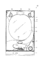
以下、遊技機の一種であるパチンコ遊技機(以下、「パチンコ機」という)の第1の実施形態を、図面に基づいて説明する。図1はパチンコ機10の正面図である。
<First Embodiment>
Hereinafter, a first embodiment of a pachinko gaming machine (hereinafter referred to as a “pachinko machine”), which is a type of gaming machine, will be described with reference to the drawings. FIG. 1 is a front view of the
パチンコ機10は、図1に示すように、当該パチンコ機10の外殻を形成する外枠11と、この外枠11に対して前方に回動可能に取り付けられた遊技機本体12とを有する。遊技機本体12は、内枠13と、その内枠13の前方に配置される前扉枠14と、内枠13の後方に配置される裏パックユニット(図示略)とを備えている。
As shown in FIG. 1, the
遊技機本体12のうち内枠13が、左右両側部のうち一方を支持側として外枠11に回動可能に支持されている。また、内枠13には、前扉枠14が回動可能に支持されており、左右両側部のうち一方を支持側として前方へ回動可能とされている。また、内枠13には、裏パックユニットが回動可能に支持されており、左右両側部のうち一方を支持側として後方へ回動可能とされている。
The
なお、遊技機本体12には、その回動先端部に施錠装置が設けられており、遊技機本体12を外枠11に対して開放不能に施錠状態とする機能を有しているとともに、前扉枠14を内枠13に対して開放不能に施錠状態とする機能を有している。これらの各施錠状態は、パチンコ機10前面にて露出させて設けられたシリンダ錠17に対して解錠キーを用いて解錠操作を行うことにより、それぞれ解除される。
The gaming machine
内枠13には遊技盤20が搭載されている。ここで、遊技盤20の構成を図2に基づいて説明する。図2は、遊技盤20の正面図である。
A
遊技盤20には、ルータ加工が施されることによって前後方向に貫通する大小複数の開口部が形成されている。各開口部には一般入賞口21,可変入賞装置22,上作動口(第1始動入球部)23,下作動口(第2始動入球部)24,スルーゲート25、可変表示ユニット26、メイン表示部33及び役物用表示部34等がそれぞれ設けられている。
The
一般入賞口21、可変入賞装置22、上作動口23及び下作動口24への入球が発生すると、それが遊技盤20の背面側に配設された検知センサにより検知され、その検知結果に基づいて所定数の賞球の払い出しが実行される。
When a ball enters the general winning
その他に、遊技盤20の最下部にはアウト口27が設けられており、各種入賞口等に入らなかった遊技球はアウト口27を通って遊技領域から排出される。また、遊技盤20には、遊技球の落下方向を適宜分散、調整等するために多数の釘28が植設されていると共に、風車等の各種部材(役物)が配設されている。
In addition, an
ここで、入球とは、所定の開口部を遊技球が通過することを意味し、開口部を通過した後に遊技領域から排出される態様だけでなく、開口部を通過した後に遊技領域から排出されない態様も含まれる。但し、以下の説明では、アウト口27への遊技球の入球と明確に区別するために、可変入賞装置22、上作動口23、下作動口24又はスルーゲート25への遊技球の入球を、入賞とも表現する。
Here, the entry ball means that the game ball passes through a predetermined opening, and is not only a mode of being discharged from the game area after passing through the opening, but is discharged from the game area after passing through the opening. Embodiments that are not included are also included. However, in the following description, in order to clearly distinguish the game ball from entering the
上作動口23及び下作動口24は、作動口装置としてユニット化されて遊技盤20に設置されている。上作動口23及び下作動口24は共に上向きに開放されている。また、上作動口23が上方となるようにして両作動口23,24は鉛直方向に並んでいる。下作動口24には、左右一対の可動片よりなるガイド片(サポート片)としての電動役物24aが設けられている。電動役物24aの閉鎖状態(非サポート状態又は非ガイド状態)では遊技球が下作動口24に入賞できず、電動役物24aが開放状態(サポート状態又はガイド状態)となることで下作動口24への入賞が可能となる。
The
可変入賞装置22は、遊技盤20の背面側へと通じる大入賞口22aを備えているとともに、当該大入賞口22aを開閉する開閉扉22bを備えている。開閉扉22bは、通常は大入賞口22aに対して遊技球が入賞できない又は入賞し難い閉鎖状態になっており、内部抽選において開閉実行モード(開閉実行状態)への移行に当選した場合に大入賞口22aに対して遊技球が入賞しやすい所定の開放状態に切り換えられるようになっている。ここで、開閉実行モードとは、大当たり当選となった場合に移行することとなるモードである。当該開閉実行モードについては、後に詳細に説明する。可変入賞装置22の開放態様としては、所定時間(例えば30sec)の経過又は所定個数(例えば10個)の入賞を1ラウンドとして、複数ラウンド(例えば15ラウンド)を上限として可変入賞装置22が繰り返し開放される態様がある。
The
なお、開閉扉22bの隣の位置にはLED22cが設けられている。当該LED22cは、開閉扉22bが開放状態である場合に発光するように構成されている。これにより、開閉扉22bが開放状態であることを認識し易くなっている。また、LED22cの発光を確認することで、開放状態に設定されている状況でないにも関わらず、強制的に開閉扉22bを開放させる不正行為を容易に発見することができる。よって、上記不正行為を抑制することができる。
An
メイン表示部33及び役物用表示部34は、遊技領域の下部側の外縁に沿って配設された装飾部材29に設けられている。装飾部材29は、遊技盤20の盤面からパチンコ機10前方に延出している。より具体的には、装飾部材29の前面は、遊技領域をパチンコ機10前方から視認可能とするために前扉枠14に設けられた窓パネル62と対向しており、さらに窓パネル62との間の距離は遊技球1個分よりも狭くなっている。これにより、装飾部材29の前面の前方を遊技球が落下していくのが防止されている。
The
装飾部材29の前面から露出するようにしてメイン表示部33及び役物用表示部34が設けられている。つまり、メイン表示部33及び役物用表示部34は、前扉枠14の窓パネル62を通じてパチンコ機10前方から視認可能となっているとともに、これら両表示部33,34の前方を遊技球が落下していくのが防止されている。
A
メイン表示部33では、上作動口23又は下作動口24への入賞をトリガとして絵柄の変動表示が行われ、その変動表示の停止結果として、上作動口23又は下作動口24への入賞に基づいて行われた内部抽選の結果が表示によって明示される。つまり、本パチンコ機10では、上作動口23への入賞と下作動口24への入賞とが内部抽選において区別されておらず、上作動口23又は下作動口24への入賞に基づいて行われた内部抽選の結果が共通の表示領域であるメイン表示部33にて明示される。そして、上作動口23又は下作動口24への入賞に基づく内部抽選の結果が開閉実行モードへの移行に対応した当選結果であった場合には、メイン表示部33にて所定の停止結果が表示されて変動表示が停止された後に、開閉実行モードへ移行する。
In the
なお、メイン表示部33は、複数のセグメント発光部が所定の態様で配列されてなるセグメント表示器により構成されているが、これに限定されることはなく、液晶表示装置、有機EL表示装置、CRT、ドットマトリックス等その他のタイプの表示装置によって構成されていてもよい。また、メイン表示部33にて変動表示される絵柄としては、複数種の文字が変動表示される構成、複数種の記号が変動表示される構成、複数種のキャラクタが変動表示される構成又は複数種の色が切り換え表示される構成などが考えられる。
The
役物用表示部34では、スルーゲート25への入賞をトリガとして絵柄の変動表示が行われ、その変動表示の停止結果として、スルーゲート25への入賞に基づいて行われた内部抽選の結果が表示によって明示される。スルーゲート25への入賞に基づく内部抽選の結果が電役開放状態への移行に対応した当選結果であった場合には、役物用表示部34にて所定の停止結果が表示されて変動表示が停止された後に、電役開放状態へ移行する。電役開放状態では、下作動口24に設けられた電動役物24aが所定の態様で開放状態となる。
The
可変表示ユニット26には、絵柄の一種である図柄を変動表示(又は、可変表示若しくは切換表示)する図柄表示装置31が設けられている。また、可変表示ユニット26には、図柄表示装置31を囲むようにしてセンターフレーム32が配設されている。このセンターフレーム32は、その上部がパチンコ機10前方に延出している。これにより、図柄表示装置31の表示画面の前方を遊技球が落下していくのが防止されており、遊技球の落下により表示画面の視認性が低下するといった不都合が生じない構成となっている。
The
図柄表示装置31は、液晶ディスプレイを備えた液晶表示装置として構成されており、後述する表示制御装置により表示内容が制御される。なお、図柄表示装置31は、液晶表示装置であることに限定されることはなく、プラズマディスプレイ装置、有機EL表示装置又はCRTといった他の表示装置であってもよい。
The
図柄表示装置31には、例えば上、中及び下に並べて図柄が表示され、これらの図柄が左右方向にスクロールされるようにして変動表示されるようになっている。この場合、図柄表示装置31における変動表示は、上作動口23又は下作動口24への入賞に基づいて開始される。すなわち、メイン表示部33において変動表示が行われる場合には、それに合わせて図柄表示装置31において変動表示が行われる。そして、例えば、開閉実行モードとして可変入賞装置22の大入賞口22aの開放が15回行われることとなる15ラウンド対応の開閉実行モードに移行する遊技回には、図柄表示装置31では予め設定されている有効ライン上に所定の組み合わせの図柄が停止表示される。
On the
ちなみに、いずれかの作動口23,24への入賞に基づいて、メイン表示部33及び図柄表示装置31にて変動表示が開始され、所定の停止結果を表示し上記変動表示が停止されるまでが遊技回の1回に相当する。
By the way, based on the winning at any one of the operating
センターフレーム32の前面側における左上部分には、メイン表示部33及び図柄表示装置31に対応した第1保留ランプ部35が設けられている。遊技球が上作動口23又は下作動口24に入賞した個数は最大4個まで保留され、第1保留ランプ部35の点灯によってその保留個数が表示されるようになっている。
A first
センターフレーム32の右上部分には、役物用表示部34に対応した第2保留ランプ部36が設けられている。遊技球がスルーゲート25を通過した回数は最大4回まで保留され、第2保留ランプ部36の点灯によってその保留個数が表示されるようになっている。なお、各保留ランプ部35,36の機能が図柄表示装置31の一部の領域における表示により果たされる構成としてもよい。
In the upper right portion of the
ここで、遊技盤20には、異常検知手段として、磁気検知センサ38が設けられている。磁気検知センサ38は、上作動口23周辺における遊技盤20の背面側に設置されている。上記のとおり開閉実行モードへ移行させるか否かの内部抽選は上作動口23への入賞をトリガとして行われるため、窓パネル62の前方において上作動口23周辺に磁石を近付け、不正に上作動口23へと遊技球を誘導させようとする行為が想定される。これに対して、磁気検知センサ38が設けられていることにより、上記磁石を用いた不正行為が行われた場合には、それを検知することが可能となる。磁気検知センサ38は後述する主制御装置と電気的に接続されており、磁気検知センサ38の検知結果は主制御装置に入力される。そして、主制御装置では磁気検知センサ38の検知結果に基づいて磁石を用いた不正行為を特定した場合には、異常報知を行うための処理を実行する。かかる異常報知の内容や具体的な処理内容については後に詳細に説明する。
Here, the
なお、磁気検知センサ38の位置は、上記のものに限定されることはなく、例えば、上記磁石を用いて一般入賞口21への入賞を不正に行わせようとする不正行為を抑制すべく、一般入賞口21周辺に磁気検知センサ38を配置してもよい。
In addition, the position of the
遊技盤20には、内レール部41と外レール部42とが取り付けられており、これら内レール部41と外レール部42とにより誘導レールが構成され、内枠13において遊技盤20の下方に搭載された遊技球発射機構(図示略)から発射された遊技球が遊技領域の上部に案内されるようになっている。遊技球発射機構は、前扉枠14に設けられた発射ハンドル43が操作されることにより遊技球の発射動作が行われる。
An
次に遊技盤20の背面側の構成について図3を用いて説明する。図3は遊技盤20の背面側の構成を示す背面図である。
Next, the configuration of the back side of the
遊技盤20の背面には、可変表示ユニット40の下方に集合板ユニット51が設けられている。集合板ユニット51には、前記一般入賞口21、可変入賞装置22、両作動口23,24に対応して且つ下流側で1カ所に集合する回収通路52が形成されている。一般入賞口21等に入賞した遊技球は何れも回収通路52を介して遊技盤20の下方に集合する。遊技盤20の下方には排出通路があり、回収通路52により遊技盤20の下方に集合した遊技球は排出通路内に導出される。なお、アウト口27も同様に排出通路に通じており、何れの入賞口にも入賞しなかった遊技球もアウト口27を介して排出通路内に導出される。
On the back of the
回収通路52において各一般入賞口21と対応する位置には、それぞれ一般入賞口用入賞検知センサ53aが設けられており、可変入賞装置22と対応する位置にはカウント用入賞検知センサ53bが設けられ、両作動口23,24に対応する位置には作動口用入賞検知センサ53cが設けられている。スルーゲート25は、当該スルーゲート25を通過する遊技球を検知するゲート用入賞検知センサ53dを備えている。これら各入賞検知センサ53a〜53dにより遊技球の入賞がそれぞれ検知される。各入賞検知センサ53a〜53dは配線を通じて両作動口23,24の裏側に設けられた中継基板54に接続されている。中継基板54は後述する主制御装置と配線を通じて接続されており、各入賞検知センサ53a〜53dによる検知結果は中継基板54を介して主制御装置に入力される。
In the
各入賞検知センサ53a〜53d及び主制御装置等の各種機器と中継基板54との接続に係る構成について具体的には、パチンコ機10は、中継基板54と各種機器とを接続するものであって、複数の配線を有するワイヤーハーネスH(以降単にハーネスHという)を備えている。ハーネスHの端部にはハーネス側コネクタHCNが設けられており、当該ハーネス側コネクタHCNに対応させて、中継基板54には上記ハーネス側コネクタHCNと接続可能な基板側コネクタSCNが複数設けられている。基板側コネクタSCNに対してハーネス側コネクタHCNを差し込むことによって、中継基板54と各種機器とが接続される。
Specifically, the
各コネクタHCN,SCNは、配線の本数に対応させて多数のピンを有しており、各配線及び各ピンを介して中継基板54及び各種機器間で複数種類の信号及び電力のやり取りを並列して行うことができる。これらの詳細な説明については後述する。
Each connector HCN, SCN has a large number of pins corresponding to the number of wires, and a plurality of types of signals and power are exchanged in parallel between the
内枠13の前面側全体を覆うようにして前扉枠14が設けられている。前扉枠14には、図1に示すように、遊技領域のほぼ全域を前方から視認することができるようにした窓部61が形成されている。窓部61は、略楕円形状をなし、上述した窓パネル62が嵌め込まれている。窓パネル62は、ガラスによって無色透明に形成されているが、これに限定されることはなく合成樹脂によって無色透明に形成してもよい。
A
窓部61の周囲には、各種ランプ等の発光手段が設けられている。当該各種ランプ部の一部として表示ランプ部63が窓部61の上方に設けられている。また、表示ランプ部63の左右両側には、遊技状態に応じた効果音などが出力されるスピーカ部64が設けられている。
Around the
前扉枠14における窓部61の下方には、手前側へ膨出した上側膨出部65と下側膨出部66とが上下に並設されている。上側膨出部65内側には上方に開口した上皿65aが設けられており、下側膨出部66内側には同じく上方に開口した下皿66aが設けられている。上皿65aは、後述する払出装置より払い出された遊技球を一旦貯留し、一列に整列させながら遊技球発射機構側へ導くための機能を有する。また、下皿66aは、上皿65a内にて余剰となった遊技球を貯留する機能を有する。上皿65a及び下皿66aには、裏パックユニットに搭載された払出装置から払い出された遊技球が排出される。
Below the
次に、遊技機本体12の背面側の構成について図4を用いて説明する。図4は、内枠13の背面図である。
Next, the configuration of the back side of the gaming machine
図4に示すように、内枠13(遊技盤20)の背面には、主制御装置ユニット71及び音声ランプ制御装置ユニット75が搭載されている。
As shown in FIG. 4, a
主制御装置ユニット71は、集合板ユニット51を後方から覆うように取り付けられている。主制御装置ユニット71は合成樹脂製の取付台72を有し、取付台72に主制御装置73が搭載されている。主制御装置73は、遊技の主たる制御を司る機能と、電源を監視する機能と、を有する主制御基板を具備しており、当該主制御基板が透明樹脂材料等よりなる基板ボックス74に収容されて構成されている。
The
なお、基板ボックス74に対して、その開放の痕跡を残すための痕跡手段を付与する又はその開放の痕跡を残すための痕跡構造を設けておくようにしてもよい。当該痕跡手段としては、基板ボックス74を構成する複数のケース体を分離不能に結合するとともにその分離に際して所定部位の破壊を要する結合部(カシメ部)の構成や、引き剥がしにして粘着層が接着対象に残ることで剥がされたことの痕跡を残す封印シールを複数のケース体間の境界を跨ぐようにして貼り付ける構成が考えられる。また、痕跡構造としては、基板ボックス74を構成する複数のケース体間の境界に対して接着剤を塗布する構成が考えられる。
In addition, you may make it provide the trace structure for giving the trace means for leaving the trace of the opening to the board |
音声ランプ制御装置ユニット75は、音声ランプ制御装置76と、取付台77とを具備する構成となっており、取付台77上に音声ランプ制御装置76が装着されている。音声ランプ制御装置76は、主制御装置ユニット71に搭載された主制御装置73からの指示に従い音声やランプ表示、及び図示しない表示制御装置の制御を司る音声ランプ制御基板を具備しており、音声ランプ制御基板が透明樹脂材料等よりなる基板ボックス78に収容されて構成されている。
The sound lamp
また、内枠の背面には既に説明したとおり裏パックユニットが設けられている。裏パックユニットは、主制御装置ユニット71の一部や音声ランプ制御装置ユニット75などを後方から覆うように設けられている。当該裏パックユニットには、払出装置を含む払出機構部と、払出制御装置と、電源及び発射制御装置とが搭載されている。以下、パチンコ機10の電気的な構成について説明する。
Further, as described above, the back pack unit is provided on the back surface of the inner frame. The back pack unit is provided so as to cover a part of the
<パチンコ機10の基本的な電気的構成>
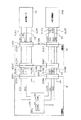
図5は、パチンコ機10の基本的な電気的構成を示すブロック図である。
<Basic electrical configuration of the
FIG. 5 is a block diagram showing a basic electrical configuration of the
主制御装置73は、遊技の主たる制御を司る主制御基板81と、電源を監視する停電監視基板85と、を具備している。主制御基板81には、MPU82が搭載されている。MPU82には、当該MPU82により実行される各種の制御プログラムや固定値データを記憶したROM83と、そのROM83内に記憶される制御プログラムの実行に際して各種のデータ等を一時的に記憶するためのメモリであるRAM84と、割込回路、タイマ回路、データ入出力回路、乱数発生器としての各種カウンタ回路などが内蔵されている。
The
MPU82には、入力ポート及び出力ポートがそれぞれ設けられている。MPU82の入力側には、主制御装置73に設けられた停電監視基板85及び払出制御装置90が接続されている。この場合に、停電監視基板85には動作電力を供給する機能を有する電源及び発射制御装置100が接続されており、MPU82には停電監視基板85を介して電力が供給される。
The
また、MPU82の入力側には、中継基板54を介して磁気検知センサ38や遊技球の検知に用いられる各種センサ53a〜53dが中継基板54を介して接続されている。磁気検知センサ38の検知結果に基づいてMPU82において磁気検知判定が行われる。また、各種センサ53a〜53dの検知結果に基づいて、MPU82において各入球部への入賞判定(入球判定)が行われる。各入球部に対して遊技球が入賞した場合、所定の数の遊技球が払い出される。
In addition, the
また、作動口用入賞検知センサ53cにて各作動口23,24への遊技球の入賞が検知された場合には、MPU82において大当たり発生抽選を実行する。さらに、ゲート用入賞検知センサ53dによってスルーゲート25への遊技球の入賞が検知された場合にはサポート発生抽選を実行する。
Further, when the winning prize for the
MPU82の出力側には、停電監視基板85、払出制御装置90及び音声ランプ制御装置76が接続されている。払出制御装置90には、例えば、入賞判定結果に基づいて賞球コマンドが出力される。この場合、賞球コマンドの出力に際しては、ROM83のコマンド情報記憶エリア83dが参照される。
A power
音声ランプ制御装置76には、変動用コマンド、種別コマンド、変動終了コマンド、オープニングコマンド及びエンディングコマンドなどの各種コマンドが出力される。この場合、これら各種コマンドの出力に際しては、ROM83のコマンド情報記憶エリア83dが参照される。これら各種コマンドの詳細については、後に説明する。
Various commands such as a change command, a type command, a change end command, an opening command, and an ending command are output to the sound
また、MPU82の出力側には、可変入賞装置22の開閉扉22bを開閉動作させるとともにLED22cを発光させる可変入賞駆動部22d、下作動口24の電動役物24aを開閉動作させる電動役物駆動部24b、メイン表示部33及び役物用表示部34が中継基板54を介して接続されている。主制御基板81には各種ドライバ回路が設けられており、当該ドライバ回路を通じてMPU82は各種駆動部の駆動制御を実行する。
Further, on the output side of the
つまり、開閉実行モードにおいては開閉扉22bが開閉されるように、MPU82において可変入賞駆動部22dの駆動制御が実行される。また、電動役物24aの開放状態当選となった場合には、電動役物24aが開閉されるように、MPU82において電動役物駆動部24bの駆動制御が実行される。また、各遊技回に際しては、MPU82においてメイン表示部33の表示制御が実行される。また、電動役物24aを開放状態とするか否かの抽選結果を明示する場合に、MPU82において役物用表示部34の表示制御が実行される。
That is, in the opening / closing execution mode, the
停電監視基板85は、主制御基板81と電源及び発射制御装置100とを中継し、また電源及び発射制御装置100から出力される最大電圧である直流安定24ボルトの電圧を監視する。払出制御装置90は、主制御装置73から入力した賞球コマンドに基づいて、払出装置91により賞球や貸し球の払出制御を行うものである。
The power
ここで、払出装置91には、遊技球が通過可能な遊技球通路が設けられており、当該遊技球通路を通って遊技球が払い出されるようになっている。遊技球通路には当該遊技球通路を流下する遊技球をカウントする払出カウントセンサ53eが設けられている。払出カウントセンサ53eは中継基板54を介して主制御基板81と接続されており、払出カウントセンサ53eの検知結果は主制御基板81のMPU82に対して入力されるようになっている。MPU82では、払出カウントセンサ53eの検知結果に基づいて払い出された遊技球数を把握し、制御する。
Here, the
電源及び発射制御装置100は、例えば、遊技場等における商用電源(外部電源)に接続されている。そして、その商用電源から供給される外部電力に基づいて主制御基板81や払出制御装置90等に対して各々に必要な動作電力を生成するとともに、その生成した動作電力を供給する。また、電源及び発射制御装置100は遊技球発射機構101の発射制御を担うものであり、遊技球発射機構101は所定の発射条件が整っている場合に駆動される。
The power source and launch
音声ランプ制御装置76は、主制御装置73から入力した各種コマンドに基づいて、前扉枠14に設けられた各種ランプ部35,36,63やスピーカ部64を駆動制御するとともに、表示制御装置110を制御するものである。表示制御装置110では、音声ランプ制御装置76から入力したコマンドに基づいて、図柄表示装置31の表示制御を実行する。
The sound
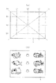
ここで、図柄表示装置31の表示内容について図6に基づいて説明する。図6は図柄表示装置31の表示画面Gを示す図である。
Here, the display content of the
図6(a)に示すように、図柄表示装置31の表示画面Gには、複数の表示領域として、上段・中段・下段の3つの図柄列Z1,Z2,Z3が設定されている。各図柄列Z1〜Z3は、「1」〜「9」の数字が各々付された9種類の主図柄と、貝形状の絵図柄からなる副図柄が所定の順序で配列されて構成されている。詳細には、上図柄列Z1には、「1」〜「9」の9種類の主図柄が数字の降順に配列されると共に、各主図柄の間に副図柄が1つずつ配されている。下図柄列Z3には、「1」〜「9」の9種類の主図柄が数字の昇順に配列されると共に、各主図柄の間に副図柄が1つずつ配されている。
As shown in FIG. 6A, on the display screen G of the
つまり、上図柄列Z1と下図柄列Z3は18個の図柄により構成されている。これに対し、中図柄列Z2には、数字の昇順に「1」〜「9」の9種類の主図柄が配列された上で「9」の主図柄と「1」の主図柄との間に「4」の主図柄が付加的に配列され、これら各主図柄の間に副図柄が1つずつ配されている。つまり、中図柄列Z2に限っては、10個の主図柄が配されて20個の図柄により構成されている。そして、表示画面Gでは、これら各図柄列Z1〜Z3の図柄が周期性をもって所定の向きにスクロールするように変動表示される。 That is, the upper symbol row Z1 and the lower symbol row Z3 are composed of 18 symbols. On the other hand, in the middle symbol row Z2, nine types of main symbols “1” to “9” are arranged in ascending numerical order, and then between the main symbol “9” and the main symbol “1”. In addition, a main symbol “4” is additionally arranged, and one sub symbol is arranged between each main symbol. In other words, only the middle symbol row Z2 is composed of 20 symbols by arranging 10 main symbols. On the display screen G, the symbols in the symbol rows Z1 to Z3 are displayed in a variable manner so as to scroll in a predetermined direction with periodicity.
図6(b)に示すように、表示画面Gは、図柄列毎に3個の図柄が停止表示されるようになっており、結果として3×3の計9個の図柄が停止表示されるようになっている。また、表示画面Gには、5つの有効ライン、すなわち左ラインL1、中ラインL2、右ラインL3、右下がりラインL4、右上がりラインL5が設定されている。そして、上図柄列Z1→下図柄列Z3→中図柄列Z2の順に変動表示が停止し、いずれかの有効ラインに同一の数字が付された図柄の組み合わせが形成された状態で全図柄列Z1〜Z3の変動表示が終了すれば、後述する通常大当たり結果又は15R確変大当たり結果の発生として大当たり動画が表示されるようになっている。 As shown in FIG. 6B, on the display screen G, 3 symbols are stopped and displayed for each symbol row, and as a result, a total of 9 symbols of 3 × 3 are stopped and displayed. It is like that. The display screen G has five effective lines, that is, a left line L1, a middle line L2, a right line L3, a right lowering line L4, and a right uppering line L5. Then, the variable display stops in the order of the upper symbol row Z1 → the lower symbol row Z3 → the middle symbol row Z2, and all the symbol rows Z1 are formed in a state in which a combination of symbols having the same number attached to any one of the effective lines is formed. When the fluctuation display of .about.Z3 is completed, the jackpot moving image is displayed as a normal jackpot result or a 15R probability variable jackpot result which will be described later.
本パチンコ機10では、奇数番号(1,3,5,7,9)が付された主図柄は「特定図柄」に相当し、15R確変大当たり結果が発生する場合には、同一の特定図柄の組み合わせが停止表示される。また、偶数番号(2,4,6,8)が付された主図柄は「非特定図柄」に相当し、通常大当たり結果が発生する場合には、同一の非特定図柄の組み合わせが停止表示される。
In this
また、後述する明示2R確変大当たり結果となる場合には、同一の図柄の組み合わせとは異なる所定の図柄の組み合わせが形成された状態で全図柄列Z1〜Z3の変動表示が終了し、その後に、明示用動画が表示されるようになっている。 In addition, when an explicit 2R probability variation jackpot result to be described later is obtained, the variation display of all the symbol rows Z1 to Z3 is finished in a state where a predetermined symbol combination different from the same symbol combination is formed, and then, An explicit video is displayed.
なお、図柄表示装置31における図柄の変動表示の態様は上記のものに限定されることはなく任意であり、図柄列の数、図柄列における図柄の変動表示の方向、各図柄列の図柄数などは適宜変更可能である。図柄表示装置31にて変動表示される絵柄は上記のような図柄に限定されることはなく、例えば絵柄として数字のみが変動表示される構成としてもよい。
In addition, the mode of the variable display of the symbol in the
<各種カウンタ及び保留球格納エリア84bについて>
次に、上記の如く構成されたパチンコ機10の動作について説明する。
<Various counters and reserved
Next, the operation of the
MPU82は遊技に際し各種カウンタ情報を用いて、大当たり発生抽選、メイン表示部33の表示の設定、図柄表示装置31の図柄表示の設定、役物用表示部34の表示の設定などを行うこととしており、具体的には、図7に示すように、大当たり発生の抽選に使用する大当たり乱数カウンタC1と、確変大当たり結果や通常大当たり結果等の大当たり種別を判定する際に使用する大当たり種別カウンタC2と、図柄表示装置31が外れ変動する際のリーチ発生抽選に使用するリーチ乱数カウンタC3と、大当たり乱数カウンタC1の初期値設定に使用する乱数初期値カウンタCINIと、メイン表示部33及び図柄表示装置31における変動表示時間を決定する変動種別カウンタCSとを用いることとしている。さらに、下作動口24の電動役物24aを電役開放状態とするか否かの抽選に使用する電動役物開放カウンタC4を用いることとしている。
The
各カウンタC1〜C3,CINI,CS,C4は、その更新の都度前回値に1が加算され、最大値に達した後0に戻るループカウンタとなっている。各カウンタは短時間間隔で更新され、その更新値がRAM84の所定領域に設定された抽選カウンタ用バッファ84aに適宜格納される。このうち抽選カウンタ用バッファ84aにおいて、大当たり乱数カウンタC1、大当たり種別カウンタC2及びリーチ乱数カウンタC3に対応した情報は、上作動口23又は下作動口24への入賞が発生した場合に、取得情報記憶手段としての保留球格納エリア84bに格納される。
Each of the counters C1 to C3, CINI, CS, and C4 is a loop counter that adds 1 to the previous value every time it is updated and returns to 0 after reaching the maximum value. Each counter is updated at short time intervals, and the updated value is appropriately stored in a
保留球格納エリア84bは、保留用エリアREと、実行エリアAEとを備えている。保留用エリアREは、第1保留エリアRE1、第2保留エリアRE2、第3保留エリアRE3及び第4保留エリアRE4を備えており、上作動口23又は下作動口24への入賞履歴に合わせて、抽選カウンタ用バッファ84aに格納されている大当たり乱数カウンタC1、大当たり種別カウンタC2及びリーチ乱数カウンタC3の各数値情報が保留情報として、いずれかの保留エリアRE1〜RE4に格納される。
The holding
この場合、第1保留エリアRE1〜第4保留エリアRE4には、上作動口23又は下作動口24への入賞が複数回連続して発生した場合に、第1保留エリアRE1→第2保留エリアRE2→第3保留エリアRE3→第4保留エリアRE4の順に各数値情報が時系列的に格納されていく。このように4つの保留エリアRE1〜RE4が設けられていることにより、上作動口23又は下作動口24への遊技球の入賞履歴が最大4個まで保留記憶されるようになっている。また、保留用エリアREは、保留数記憶エリアNAを備えており、当該保留数記憶エリアNAには上作動口23又は下作動口24への入賞履歴を保留記憶している数を特定するための情報が格納される。
In this case, in the first reservation area RE1 to the fourth reservation area RE4, when the winning to the
なお、保留記憶可能な数は、4個に限定されることはなく任意であり、2個、3個又は5個以上といったように他の複数であってもよく、単数であってもよい。 Note that the number that can be reserved and stored is not limited to four, but may be any other number such as two, three, or five or more.
実行エリアAEは、メイン表示部33の変動表示を開始する際に、保留用エリアREの第1保留エリアRE1に格納された各値を移動させるためのエリアであり、1遊技回の開始に際しては実行エリアAEに記憶されている各種数値情報に基づいて、当否判定などが行われる。
The execution area AE is an area for moving each value stored in the first holding area RE1 of the holding area RE when starting the variable display on the
上記各カウンタについて詳細に説明する。 Each counter will be described in detail.
各カウンタについて詳しくは、大当たり乱数カウンタC1は、例えば0〜599の範囲内で順に1ずつ加算され、最大値に達した後0に戻る構成となっている。特に大当たり乱数カウンタC1が1周した場合、その時点の乱数初期値カウンタCINIの値が当該大当たり乱数カウンタC1の初期値として読み込まれる。なお、乱数初期値カウンタCINIは、大当たり乱数カウンタC1と同様のループカウンタである(値=0〜599)。大当たり乱数カウンタC1は定期的に更新され、遊技球が上作動口23又は下作動口24に入賞したタイミングでRAM84の保留球格納エリア84bに格納される。
For details of each counter, the jackpot random number counter C1 is configured such that, for example, 1 is sequentially added within a range of 0 to 599, and after reaching the maximum value, it returns to 0. In particular, when the jackpot random number counter C1 makes one round, the value of the random number initial value counter CINI at that time is read as the initial value of the jackpot random number counter C1. The random number initial value counter CINI is a loop counter similar to the jackpot random number counter C1 (value = 0 to 599). The big hit random number counter C <b> 1 is periodically updated and stored in the reserved
大当たり当選となる乱数の値は、ROM83における当否情報群記憶手段としての当否テーブル記憶エリア83aに当否テーブル(当否情報群)として記憶されている。当否テーブルとしては、低確率モード用の当否テーブル(低確率用当否情報群)と、高確率モード用の当否テーブル(高確率用当否情報群)とが設定されている。つまり、本パチンコ機10は、当否抽選手段における抽選モードとして、低確率モード(低確率状態)と高確率モード(高確率状態)とが設定されている。
The value of the random number for winning the big hit is stored as a success / failure table (availability information group) in a success / failure
上記抽選に際して低確率モード用の当否テーブルが参照されることとなる遊技状態下では、大当たり当選となる乱数の数は2個である。一方、上記抽選に際して高確率モード用の当否テーブルが参照されることとなる遊技状態下では、大当たり当選となる乱数の数は20個である。なお、低確率モードよりも高確率モードの方の当選確率が高くなるのであれば、上記当選となる乱数の数は任意である。 In the gaming state in which the winning / failing table for the low probability mode is referred to at the time of the lottery, the number of random numbers that win the jackpot is two. On the other hand, in the gaming state in which the winning / failing table for the high probability mode is referred to at the time of the lottery, the number of random numbers that will win the jackpot is 20. If the winning probability in the high probability mode is higher than that in the low probability mode, the number of random numbers to be won is arbitrary.
大当たり種別カウンタC2は、0〜29の範囲内で順に1ずつ加算され、最大値に達した後0に戻る構成となっている。大当たり種別カウンタC2は定期的に更新され、遊技球が上作動口23又は下作動口24に入賞したタイミングでRAM84の保留球格納エリア84bに格納される。
The jackpot type counter C2 is configured so that 1 is added in order within a range of 0 to 29, and after reaching the maximum value, it returns to 0. The big hit type counter C <b> 2 is periodically updated and stored in the reserved
大当たり種別カウンタC2に対する遊技結果の振分先(すなわち、当否抽選及び振分抽選による抽選結果)は、ROM83における振分情報群記憶手段としての振分テーブル記憶エリア83bに振分テーブル(振分情報群)として記憶されている。そして、かかる振分先として、通常大当たり結果(低確率対応特別遊技結果)と、確変大当たり結果(高確率対応特別遊技結果)とが設定されている。
The game result distribution destination for the jackpot type counter C2 (that is, the lottery result by the success / failure lottery and the distribution lottery) is assigned to the distribution table (distribution information) in the distribution
通常大当たり結果は、開閉実行モードの終了後には、当否抽選モードが低確率モードとなる大当たり結果である。換言すれば、通常大当たり結果は、通常大当たり状態(低確率対応特別遊技状態)へ遊技状態を移行させる大当たり結果である。 The normal jackpot result is a jackpot result in which the success / failure lottery mode becomes the low probability mode after the opening / closing execution mode ends. In other words, the normal jackpot result is a jackpot result for shifting the gaming state to the normal jackpot state (special gaming state corresponding to low probability).
確変大当たり結果は、開閉実行モードの終了後には、当否抽選モードが高確率モードとなる大当たり結果である。これら高確率モードは、当否抽選における抽選結果が大当たり状態当選となり、それによる大当たり状態に移行するまで継続する。換言すれば、確変大当たり結果は、確変大当たり状態(高確率対応特別遊技状態)へ遊技状態を移行させる大当たり結果である。 The probability variation jackpot result is a jackpot result in which the success / failure lottery mode becomes the high probability mode after the opening / closing execution mode ends. These high-probability modes continue until the lottery result in the success / failure lottery becomes a big hit state win and shifts to the big hit state by that. In other words, the probability variation jackpot result is a jackpot result in which the gaming state is shifted to the probability variation jackpot state (the special gaming state corresponding to high probability).
なお、上記各遊技状態との関係で通常遊技状態とは、当否抽選モードが低確率モードである状態をいう。 Note that the normal gaming state in relation to each of the above gaming states refers to a state where the winning lottery mode is a low probability mode.
振分テーブルでは、「0〜29」の大当たり種別カウンタC2の値のうち、「0〜9」が通常大当たり結果に対応しており、「10〜29」が15R確変大当たり結果に対応している。 In the distribution table, among the values of the jackpot type counter C2 of “0 to 29”, “0 to 9” corresponds to the normal jackpot result, and “10 to 29” corresponds to the 15R probability variable jackpot result. .
リーチ乱数カウンタC3は、例えば0〜238の範囲内で順に1ずつ加算され、最大値に達した後0に戻る構成となっている。リーチ乱数カウンタC3は定期的に更新され、遊技球が上作動口23又は下作動口24に入賞したタイミングでRAM84の保留球格納エリア84bに格納される。
For example, the reach random number counter C3 is incremented one by one within a range of 0 to 238, for example, and reaches a maximum value and then returns to 0. The reach random number counter C3 is periodically updated and stored in the reserved
ここで、本パチンコ機10には、図柄表示装置31における表示演出の一種として期待演出が設定されている。期待演出とは、図柄(絵柄)の変動表示(又は可変表示)を行うことが可能な図柄表示装置31を備え、可変入賞装置22の開閉実行モードに移行する遊技回では変動表示後の停止表示結果が特別表示結果となる遊技機において、図柄表示装置31における図柄(絵柄)の変動表示(又は可変表示)が開始されてから停止表示結果が導出表示される前段階で、前記特別表示結果となり易い変動表示状態であると遊技者に思わせるための表示状態をいう。
Here, in this
期待演出には、リーチ表示と、当該リーチ表示が発生する前段階などにおいてリーチ表示の発生や特別表示結果の発生を期待させるための予告表示との2種類が設定されている。 In the expected effect, two types of reach display and a notice display for expecting generation of reach display or generation of a special display result at a stage before the reach display occurs are set.
リーチ表示には、図柄表示装置31の表示画面Gに表示される複数の図柄列Z1〜Z3のうち一部の図柄列について図柄を停止表示させることで、大当たり図柄の組み合わせが成立する可能性があるリーチ図柄の組み合わせを表示し、その状態で残りの図柄列において図柄の変動表示を行う表示状態が含まれる。また、上記のようにリーチ図柄の組み合わせを表示した状態で、残りの図柄列において図柄の変動表示を行うとともに、その背景画面において所定のキャラクタなどを動画として表示することによりリーチ演出を行うものや、リーチ図柄の組み合わせを縮小表示させる又は非表示とした上で、表示画面Gの略全体において所定のキャラクタなどを動画として表示することによりリーチ演出を行うものが含まれる。
In the reach display, there is a possibility that a combination of jackpot symbols may be established by stopping and displaying symbols for some of the symbol rows Z1 to Z3 displayed on the display screen G of the
図柄の変動表示に係るリーチ表示について具体的には、図柄の変動表示を終了させる前段階として、図柄表示装置31の表示画面内の予め設定された有効ライン上に、大当たり図柄の組み合わせが成立する可能性のあるリーチ図柄の組み合わせを停止表示させることによりリーチラインを形成させ、当該リーチラインが形成されている状況下において最終停止図柄列により図柄の変動表示を行うことである。
Specifically, for the reach display related to the symbol variation display, a combination of jackpot symbols is established on a preset effective line in the display screen of the
図6の表示内容について具体的に説明すると、最初に上段の図柄列Z1において図柄の変動表示が終了され、さらに下段の図柄列Z3において図柄の変動表示が終了された状態において、いずれかの有効ラインL1〜L5に同一の数字が付された主図柄が停止表示されることでリーチラインが形成され、当該リーチラインが形成されている状況化において中段の図柄列Z2において図柄の変動表示が行われることでリーチ表示となる。そして、遊技結果が大当たり結果である場合には、リーチラインを形成している主図柄と同一の数字が付された主図柄がリーチライン上に停止表示されるようにして中段の図柄列Z2における図柄の変動表示が終了される。 The display contents in FIG. 6 will be described in detail. In the state where the symbol variation display is first ended in the upper symbol row Z1 and the symbol variation display is further terminated in the lower symbol row Z3, any one of the effective items is displayed. A reach line is formed by stopping and displaying the main symbols having the same numbers on the lines L1 to L5, and in the situation where the reach line is formed, the symbol variation display is performed in the middle symbol row Z2. Reach display. If the game result is a jackpot result, the main symbol with the same number as the main symbol forming the reach line is stopped and displayed on the reach line in the middle symbol row Z2. The symbol variation display is terminated.
予告表示には、図柄表示装置31の表示画面Gにおいて図柄の変動表示が開始されてから、全ての図柄列Z1〜Z3にて図柄が変動表示されている状況において、又は一部の図柄列であって複数の図柄列にて図柄が変動表示されている状況において、図柄列Z1〜Z3上の図柄とは別にキャラクタを表示させる態様が含まれる。また、背景画面をそれまでの態様とは異なる所定の態様とするものや、図柄列Z1〜Z3上の図柄をそれまでの態様とは異なる所定の態様とするものも含まれる。かかる予告表示は、リーチ表示が行われる場合及びリーチ表示が行われない場合のいずれの遊技回においても発生し得るが、リーチ表示の行われる場合の方がリーチ表示の行われない場合よりも高確率で発生するように設定されている。
In the notice display, in a situation where the symbols are variably displayed in all the symbol columns Z1 to Z3 after the symbol variation display is started on the display screen G of the
変動種別カウンタCSは、例えば0〜198の範囲内で順に1ずつ加算され、最大値に達した後0に戻る構成となっている。変動種別カウンタCSは、メイン表示部33における変動表示時間と、図柄表示装置31における図柄の変動表示時間とをMPU82において決定する上で用いられる。変動種別カウンタCSは、後述する通常処理が1回実行される毎に1回更新され、当該通常処理内の残余時間内でも繰り返し更新される。そして、メイン表示部33における変動表示の開始時及び図柄表示装置31による図柄の変動開始時における変動パターン決定に際して変動種別カウンタCSのバッファ値が取得される。
The variation type counter CS is, for example, incremented by 1 within a range of 0 to 198, and returns to 0 after reaching the maximum value. The variation type counter CS is used when the
電動役物開放カウンタC4は、例えば、0〜250の範囲内で順に1ずつ加算され、最大値に達した後0に戻る構成となっている。電動役物開放カウンタC4は定期的に更新され、スルーゲート25に遊技球が入賞したタイミングでRAM84の電役保留エリア84cに格納される。そして、所定のタイミングにおいて、その格納された電動役物開放カウンタC4の値によって電動役物24aを開放状態に制御するか否かの抽選が行われる。
The electric accessory release counter C4 is, for example, configured to increment one by one within a range of 0 to 250 and return to 0 after reaching the maximum value. The electric accessory release counter C4 is periodically updated, and stored in the electric
既に説明したように、MPU82では、少なくとも変動種別カウンタCSのバッファ値を用いて、メイン表示部33における変動表示時間が決定されるが、その決定に際してはROM83の変動表示時間テーブル記憶エリア83cが用いられる。
As described above, in the
<主制御基板81及び各種機器間で行われる電力及び信号のやり取りに係る構成>
次に、主制御基板81と中継基板54を介して接続されている各種機器(遊技手段)との間で行われる信号及び電力のやり取りに係る構成について図8を用いて説明する。ここで、説明の便宜上、各種機器のうち磁気検知センサ38及び可変入賞駆動部22dについて説明する。図8は、主制御基板81と各種機器としての磁気検知センサ38及び可変入賞駆動部22dとの接続に係る構成を示すブロック図である。
<Configuration relating to power and signal exchange between the
Next, a configuration related to the exchange of signals and power performed between the
本パチンコ機10は、磁気検知センサ38と主制御基板81とを接続するのに用いられる2つの第1ハーネスH1,H2を備えているとともに、可変入賞駆動部22dと主制御基板81とを接続するのに用いられる2つの第2ハーネスH3,H4を備えている。両第1ハーネスH1,H2を介して磁気検知センサ38と主制御基板81との間で電力及び信号のやり取りが行われるように構成されているとともに、両第2ハーネスH3,H4を介して可変入賞駆動部22dと主制御基板81との間で電力及び信号のやり取りが行われるように構成されている。
The
先ず、主制御基板81と磁気検知センサ38との電気的接続に係る構成について詳細に説明すると、第1ハーネスH1の両端部には、主制御基板81と磁気検知センサ38との間でやり取りされる信号数に対応させて形成されたハーネス側コネクタHCN1,HCN2が設けられている。ハーネス側コネクタHCN1,HCN2はメス型のコネクタであり、複数の差込口を有している。
First, the configuration relating to the electrical connection between the
各ハーネス側コネクタHCN1,HCN2に対応させて、主制御基板81及び中継基板54にはそれぞれ、ハーネス側コネクタHCN1,HCN2に対して差込可能なオス型の基板側コネクタSCN1,SCN2が設けられている。各ハーネス側コネクタHCN1,HCN2に対して各基板側コネクタSCN1,SCN2がそれぞれ差し込まれることによって、主制御基板81と中継基板54とが電気的に接続される。
Corresponding to the harness side connectors HCN1 and HCN2, the
第1ハーネスH2の端部には、上記第1ハーネスH1のハーネス側コネクタHCN1,HCN2と同一のハーネス側コネクタHCN3が設けられており、当該ハーネス側コネクタHCN3に対応させて、中継基板54には基板側コネクタSCN3が設けられている。基板側コネクタSCN3は、中継基板54に設けられた導線パターンを介して基板側コネクタSCN2と電気的に接続されており、上記基板側コネクタSCN2を介して主制御基板81から入力された電力及び信号をそのまま出力するように構成されている。基板側コネクタSCN3に対してハーネス側コネクタHCN3が差し込まれることで、中継基板54と磁気検知センサ38とが電気的に接続される。以上の接続によって、主制御基板81と磁気検知センサ38とが電気的に接続される。
The same harness side connector HCN3 as the harness side connectors HCN1 and HCN2 of the first harness H1 is provided at the end of the first harness H2. A board-side connector SCN3 is provided. The board-side connector SCN3 is electrically connected to the board-side connector SCN2 via a conductor pattern provided on the
なお、主制御基板81と可変入賞駆動部22dとの電気的接続に係る構成についても上記主制御基板81と磁気検知センサ38との接続に係る構成と同様である。具体的には、第2ハーネスH3の両端部には主制御基板81と可変入賞駆動部22dとの間でやり取りされる信号数に対応したハーネス側コネクタHCN4,HCN5が設けられており、各ハーネス側コネクタHCN4,HCN5に対応させて、主制御基板81及び中継基板54にはそれぞれ、ハーネス側コネクタHCN4,HCN5に対して差込可能な基板側コネクタSCN4,SCN5が設けられている。
The configuration related to the electrical connection between the
第2ハーネスH4の端部には、上記ハーネス側コネクタHCN4,HCN5と同一のハーネス側コネクタHCN6が設けられており、当該ハーネス側コネクタHCN6に対応させて、中継基板54には基板側コネクタSCN6が設けられている。基板側コネクタSCN6は、上述した基板側コネクタSCN5と電気的に接続されており、上記基板側コネクタSCN5を介して入力された電力及び信号をそのまま出力するように構成されている。 A harness-side connector HCN6 that is the same as the harness-side connectors HCN4 and HCN5 is provided at an end of the second harness H4. Is provided. The board-side connector SCN6 is electrically connected to the board-side connector SCN5 described above, and is configured to output the power and signals input through the board-side connector SCN5 as they are.
各基板側コネクタSCN4,SCN5,SCN6に対して、対応するハーネス側コネクタHCN4,HCN5,HCN6がそれぞれ差し込まれることで、中継基板54と可変入賞駆動部22dとが電気的に接続される。磁気検知センサ38及び可変入賞駆動部22dには、各ハーネスH1〜H4を介して主制御基板81から動作に必要な動作電力が供給されており、磁気検知センサ38及び可変入賞駆動部22dは、動作電力が供給されている場合に所定の動作(検知又は駆動)を行うように構成されている。
The corresponding harness-side connectors HCN4, HCN5, and HCN6 are respectively inserted into the board-side connectors SCN4, SCN5, and SCN6, thereby electrically connecting the
先ず、磁気検知センサ38に対応する構成について具体的に説明すると、第1ハーネスH1,H2は、複数の配線のうち磁気検知センサ38が正常に動作するのに要する動作電力を伝送する電源線ELN1を備えているとともに、磁気検知センサ38を接地させる(基準電位を設定する)のに用いるグランド線GLN1を備えている。電源線ELN1は基板側コネクタSCN1及び主制御基板81に設けられたバスを介してMPU82に接続されており、MPU82は、電源線ELN1を介して所定の駆動電圧(例えば直流+5V)を出力する。これにより、磁気検知センサ38には電源線ELN1を介して+5Vが入力される。
First, the configuration corresponding to the
主制御基板81においてグランド線GLN1は接地されている。これにより、磁気検知センサ38にはグランド線GLN1を介して接地に対応した電圧、すなわち0Vが入力される。よって、例えば磁気検知センサ38の所定の抵抗を介して電源線ELN1とグランド線GLN1とを接続することにより、当該所定の抵抗に対して+5Vの電圧を印加するとともに当該所定の抵抗に対して所定の電流を流すことが可能となる。この場合、電源線ELN1及びグランド線GLN1によって磁気検知センサ38が動作する動作電力が供給されるとも言える。
In the
なお、電源線ELN1が常時+5Vの電圧を伝送していることに鑑みれば、電源線ELN1は常時HI信号を伝送しているものとも言え、グランド線GLN1が常時基準電位(0V)を伝送していることに鑑みれば、グランド線GLN1は常時LOW信号を伝送しているものとも言える。 In view of the fact that the power line ELN1 always transmits a voltage of + 5V, it can be said that the power line ELN1 always transmits the HI signal, and the ground line GLN1 always transmits the reference potential (0V). In view of this, it can be said that the ground line GLN1 always transmits a LOW signal.
ここで、第1ハーネスH1,H2の複数の配線には、磁気検知センサ38による検知結果を主制御基板81のMPU82に対して伝送する検知信号線LN0が含まれている。磁気検知センサ38は、磁気を検知した場合には所定の検知信号SG0を出力するように構成されている。そして、当該検知信号SG0は、検知信号線LN0及び主制御基板81に設けられたバスを介してMPU82に対して入力される。MPU82は、磁気検知センサ38の検知信号SG0に基づいて所定の処理を実行するように構成されている。なお、検知信号SG0の出力に係る詳細な構成及びMPU82にて実行される処理の詳細については後述する。
Here, the plurality of wirings of the first harnesses H1 and H2 include a detection signal line LN0 that transmits a detection result by the
次に、可変入賞駆動部22dに対応する構成について具体的に説明すると、第2ハーネスH3,H4は、複数の配線のうち可変入賞駆動部22d及びLED22cが正常に動作するのに必要な動作電力を供給する電源線ELN2を備えているとともに、これらを接地するのに用いるグランド線GLN2を備えている。電源線ELN2はMPU82に接続されており、MPU82は、電源線ELN2を介して所定の駆動電圧(例えば直流+12V)を出力する。これにより、可変入賞駆動部22dには電源線ELN2を介して+12Vが入力される。なお、グランド線GLN2に関しては、上述したグランド線GLN1と同一であるため、説明を省略する。
Next, the configuration corresponding to the variable winning
ここで、第2ハーネスH3,H4の複数の配線には、可変入賞駆動部22dの駆動制御を行うための第1制御信号SG1を伝送する第1信号線LN1が含まれているとともに、LED22cの駆動制御を行うための第2制御信号SG2を伝送する第2信号線LN2が含まれている。各信号線LN1,LN2は、主制御基板81に設けられたバスを介してMPU82と接続されている。MPU82は、各信号線LN1,LN2を介してそれぞれ別系統で各制御信号SG1,SG2を可変入賞駆動部22dに向けて出力する。可変入賞駆動部22dは、電源線ELN2及びグランド線GLN2によって上記所定の駆動電圧が印加されている状況において、第1制御信号SG1に基づいて開閉扉22bの開閉制御を行うとともに、第2制御信号SG2に基づいてLED22cの発光制御を行うように構成されている。
Here, the plurality of wirings of the second harnesses H3 and H4 include the first signal line LN1 for transmitting the first control signal SG1 for performing the drive control of the variable
ここで、各基板側コネクタSCN1〜SCN6は、複数の配線に対応させて複数のピンを備えており、当該複数のピンに対応させて、各ハーネス側コネクタHCN1〜HCN6は上記複数のピンがそれぞれ挿入可能な差込口を備えている。これにより、動作電力及び信号のやり取りをそれぞれ独立して(並列で)行うことができる。この場合、やり取りを行う信号の数に応じてピン数が決められている。 Here, each of the board-side connectors SCN1 to SCN6 includes a plurality of pins corresponding to a plurality of wirings, and each of the harness-side connectors HCN1 to HCN6 includes a plurality of pins corresponding to the plurality of pins. It has an insertable slot. As a result, the operation power and the signal can be exchanged independently (in parallel). In this case, the number of pins is determined according to the number of signals to be exchanged.
かかる構成において、各基板側コネクタSCN1〜SCN6と各ハーネス側コネクタHCN1〜HCN6との接続部分において、何らかの要因によってピン同士が接触し、短絡するおそれがある。これに対して、本実施形態によれば、伝送を行う信号の種類に応じて基板側コネクタSCN1〜SCN6のピン配列が決定されている。以下、当該ピン配列について詳細に説明する。 In such a configuration, pins may come into contact with each other and be short-circuited for some reason at the connection portion between each board-side connector SCN1 to SCN6 and each harness-side connector HCN1 to HCN6. On the other hand, according to the present embodiment, the pin arrangement of the board-side connectors SCN1 to SCN6 is determined according to the type of signal to be transmitted. Hereinafter, the pin arrangement will be described in detail.
なお、磁気検知センサ38に対応した各基板側コネクタSCN1〜SCN3は同一の構成であるため、基板側コネクタSCN3について説明し、その他の基板側コネクタSCN1,SCN2については、説明を省略する。同様に、可変入賞駆動部22dに対応した各基板側コネクタSCN4〜SCN6の各構成は同一であるため、基板側コネクタSCN6について説明する。
Since the board-side connectors SCN1 to SCN3 corresponding to the
先ず、磁気検知センサ38に対応した基板側コネクタSCN3の構成について図9を用いて説明する。図9(a)は基板側コネクタSCN3のピン配列を示す概略図、図9(b)は磁気検知センサ38の回路図である。
First, the configuration of the board-side connector SCN3 corresponding to the
図9(a)に示すように、基板側コネクタSCN3は、当該基板側コネクタSCN3の外枠を構成するハウジング121を備えている。ハウジング121は絶縁性材料から構成されており、一方に開口した直方体形状をなしている。当該ハウジング121によって囲まれた長尺状のピン配列領域122が形成されている。
As shown in FIG. 9A, the board-side connector SCN3 includes a
ピン配列領域122には、一列に配列された4つのピンが形成されている。各ピンは等間隔に配列されている。これら配列されたピンには、電源線ELN1に接続される電源ピンPE1と、グランド線GLN1に接続されるグランドピンPG1と、検知信号線LN0に接続される信号ピンPS0と、が含まれている。なお、ピン同士を区別するため、図9(a)においてはこれらのピンをハッチングして示す。なお、以下の説明においても同様である。
In the
電源ピンPE1及びグランドピンPG1は、ピン配列領域122の両端に設けられており、信号ピンPS0はピン配列領域122のうちグランドピンPG1寄りに設けられている。そして、信号ピンPS0と電源ピンPE1との間には、フローティングに設定されたダミーピンPDが設けられている。信号ピンPS0は、ダミーピンPDを介して電源ピンPE1から離間した位置に設けられている。換言すれば、信号ピンPS0と電源ピンPE1とは、互いに隣接しないように配置されている。これにより、信号ピンPS0と電源ピンPE1とが短絡しにくい。
The power supply pin PE1 and the ground pin PG1 are provided at both ends of the
かかる構成によれば、仮に電源ピンPE1がピン配列領域122の中央側に向けて曲がった場合、電源ピンPE1は隣のダミーピンPDと当接し、短絡する。この場合、ダミーピンPDが邪魔になり、信号ピンPS0に対して電源ピンPE1が接触しにくい。これにより、信号ピンPS0に対して電源ピンPE1が接触することがほとんどないため、信号ピンPS0及び検知信号SG0を伝送する検知信号SG0の信頼性が確保されている。
According to this configuration, if the power supply pin PE1 is bent toward the center side of the
特に、ダミーピンPDはフローティングであるため、電源ピンPE1とダミーピンPDとの短絡による駆動電圧への影響が少ない。これにより、磁気検知センサ38への動作電力の供給に支障が生じにくい。よって、信号ピンPS0と電源ピンPE1との短絡を抑制しつつ、駆動電圧の安定した供給を行うことができる。
In particular, since the dummy pin PD is floating, the short circuit between the power supply pin PE1 and the dummy pin PD has little influence on the drive voltage. As a result, the supply of operating power to the
また、ダミーピンPDが設けられている分だけ、信号ピンPS0及び電源ピンPE1間の距離が大きくなっている。これにより、検知信号線LN0を伝送する信号と電源線ELN1を伝送する駆動電圧との間での相互作用の影響が小さくなるため、当該相互作用によって発生するノイズによる影響が小さくなる。これにより、例えば電源ピンPE1に対してノイズが混入した場合であっても、当該ノイズの影響が検知信号線LN0を伝送する信号に対して及びにくくなるため、ノイズに対する検知信号線LN0の信号の信頼性が高められている。 Further, the distance between the signal pin PS0 and the power supply pin PE1 is increased by the provision of the dummy pin PD. As a result, the influence of the interaction between the signal transmitted through the detection signal line LN0 and the drive voltage transmitted through the power supply line ELN1 is reduced, and thus the influence of noise generated by the interaction is reduced. Thereby, for example, even when noise is mixed into the power supply pin PE1, the influence of the noise is less likely to affect the signal transmitted through the detection signal line LN0. Reliability is enhanced.
特に、グランドピンPG1と電源ピンPE1とはダミーピンPD及び信号ピンPS0を介して配置されているため、両者が短絡しにくい。これにより、両者が短絡することによって、大電流が流れ、各種機器が破壊するといった不都合を回避することができる。 In particular, since the ground pin PG1 and the power supply pin PE1 are arranged via the dummy pin PD and the signal pin PS0, both are not easily short-circuited. Thereby, when both are short-circuited, the inconvenience that a large current flows and various devices are destroyed can be avoided.
次に、上記基板側コネクタSCN3を用いて接続された磁気検知センサ38の具体的な構成について図9(b)を用いて説明する。
Next, a specific configuration of the
図9(b)に示すように、磁気検知センサ38は、外部から磁界が付与されることによってOFFからONとなるリードスイッチ131と、当該リードスイッチ131に対して直列に接続された抵抗132と、を備えている。リードスイッチ131及び抵抗132から構成される直列接続体に対して駆動電圧が付与されるようになっている。具体的には、直列接続体の一端(リードスイッチ131の一端)に電源線ELN1が接続されており、直列接続体の他端(抵抗132の一端)にグランド線GLN1が接続されている。そして、直列接続体の中点、詳細にはリードスイッチ131と抵抗132とを接続する配線上に検知信号線LN0が接続されている。
As shown in FIG. 9B, the
かかる構成によれば、外部からの磁界が付与されていない場合、リードスイッチ131はOFFであるため、抵抗132には駆動電圧が付与されない。この場合、検知信号線LN0の電圧はグランド線GLN1の電圧と同一であり、詳細にはLOW信号(0V)が出力される。
According to this configuration, when an external magnetic field is not applied, the
一方、外部から磁界が付与されている場合には、リードスイッチ131がONとなり、抵抗132に対して駆動電圧が印加される。この場合、検知信号線LN0には、HI信号に対応した電圧、詳細には駆動電圧とほぼ同一の電圧が出力されることとなる。すなわち、検知信号SG0は、通常状態においてLOW信号であって磁気を検知した場合にHI信号となる信号である。MPU82は、検知信号線LN0から入力される検知信号SG0がHI信号となっていることに基づいて、磁気検知センサ38が磁気を検知していると認識し、磁気検知に対応した処理を実行するようになっている。
On the other hand, when a magnetic field is applied from the outside, the
なお、ダミーピンPDはいずれの機器にも接続されておらず、フローティングとなっている。 The dummy pin PD is not connected to any device and is in a floating state.
また、磁気検知センサ38の構成についてはこれに限られず、磁気を検知した場合に検知信号SG0がLOW信号からHI信号に切り換わる回路であれば任意である。
Further, the configuration of the
次に、可変入賞駆動部22dとMPU82との接続に用いられる基板側コネクタSCN6について図10を用いて説明する。図10(a)は基板側コネクタSCN6のピン配列を示す概略図、図10(b)は可変入賞駆動部22dの回路図である。
Next, the board-side connector SCN6 used for connecting the variable winning
図10(a)に示すように、基板側コネクタSCN6は、当該基板側コネクタSCN6の外枠を構成するハウジング141を備えている。ハウジング141は絶縁性材料から構成されており、一方に開口した直方体形状をなしている。当該ハウジング141によって囲まれた長尺状のピン配列領域142が形成されている。
As shown in FIG. 10A, the board-side connector SCN6 includes a
ピン配列領域142には一列に配列された4つのピンが形成されている。4つのピンは等間隔に配置されている。当該4つのピンには、電源ピンPE2及びグランドピンPG2が含まれているとともに、開閉扉22bの制御に用いられる第1制御信号SG1を伝送する第1信号線LN1に対して接続する第1信号ピンPS1、及びLED22cの制御に用いられる第2制御信号SG2を伝送する第2信号線LN2に対して接続する第2信号ピンPS2が含まれている。電源ピンPE2及びグランドピンPG2はピン配列領域142の両端に設けられており、その間に第1信号ピンPS1及び第2信号ピンPS2が設けられている。詳細にはグランドピンPG2よりも電源ピンPE2寄りに(電源ピンPE2の隣に)第1信号ピンPS1が設けられており、電源ピンPE2よりもグランドピンPG2寄りに(グランドピンPG2の隣に)第2信号ピンPS2が設けられている。MPU82から出力された第1制御信号SG1は第1信号ピンPS1及び第1信号線LN1を介して可変入賞駆動部22dに入力されるとともに、MPU82から出力された第2制御信号SG2は第2信号ピンPS2及び第2信号線LN2を介して可変入賞駆動部22dに入力され、可変入賞駆動部22dは、各制御信号SG1,SG2に応じて開閉扉22bの開閉動作を行うとともに、LED22cの発光を行う。
In the
可変入賞駆動部22dの電気的構成について図10(b)を用いて説明する。
The electrical configuration of the variable winning
図10(b)に示すように、可変入賞駆動部22dは、開閉用回路151と、当該開閉用回路151に対して並列に接続されたLED用回路152と、を備えている。これらの回路151,152はそれぞれ電源線ELN2及びグランド線GLN2に対して接続されている。そして、開閉用回路151に対して第1信号線LN1が接続されており、LED用回路152に対して第2信号線LN2が接続されている。
As shown in FIG. 10B, the variable
各回路151,152について詳細には、開閉用回路151は、開閉扉22bの開閉させる直流駆動式のソレノイド161と、当該ソレノイド161に対する電圧を制御するp型MOSFET162と、を備えている。ソレノイド161は所定の動作電力が付与されることによって開閉扉22bを開放するように構成されている。ソレノイド161の一端(詳細にはソレノイド161を構成するコイルの一端)はグランド線GLN2に接続されている。ソレノイド161の他端はp型MOSFET162のドレインに接続されている。p型MOSFET162のソースは電源線ELN2に接続されており、p型MOSFET162のゲートは第1信号線LN1に接続されている。
Specifically, the open /
かかる構成によれば、第1信号線LN1を介してp型MOSFET162のゲートに対してHI信号が入力されている場合には、p型MOSFET162はOFFであるため、ソレノイド161には電流が流れない。このため、ソレノイド161は駆動せず、開閉扉22bは閉鎖されている。一方、第1信号線LN1からLOW信号が出力されている場合には、p型MOSFET162はONとなるため、ソレノイド161(詳細にはソレノイド161を構成するコイル)に対して電流が流れ、ソレノイド161が駆動し、開閉扉22bが開放される。すなわち、開閉用回路151は第1制御信号SG1がLOW信号である場合に動作するように構成されているLOWアクティブ回路である。
According to this configuration, when the HI signal is input to the gate of the p-
次に、LED用回路152について説明すると、LED用回路152は、LED22cと、当該LED22cに対する電圧を制御するn型MOSFET163と、を備えている。LED22cのアノードは電源線ELN2に対して接続されており、カソードはn型MOSFET163のドレインに接続されている。n型MOSFET163のソースはグランド線GLN2に接続されており、n型MOSFET163のゲートは第2信号線LN2と接続されている。
Next, the
かかる構成によれば、第2信号線LN2を介してn型MOSFET163のゲートに対してLOW信号が入力されている場合には、n型MOSFET163はOFFであるため、LED22cには電流が流れない。このため、LED22cは発光しない。一方、第2信号線LN2を介してn型MOSFET163のゲートに対してHI信号が入力されている場合には、n型MOSFET163はONとなり、LED22cに電流が流れる。これにより、LED22cは発光する。すなわち、LED用回路152は第2制御信号SG2がHI信号である場合に動作するように構成されたHIアクティブ回路である。
According to such a configuration, when a LOW signal is input to the gate of the n-
ここで、既に説明した通り、第1信号ピンPS1はグランドピンPG2から離間した位置に配置されているとともに、当該第1信号ピンPS1とグランドピンPG2との間には第2信号ピンPS2が設けられているため、第1信号ピンPS1とグランドピンPG2とが短絡しにくくなっている。この場合、第1信号ピンPS1は電源ピンPE2の隣に配置されているため、仮に電源ピンPE2がピン配列領域142の内側に曲がった場合、電源ピンPE2と第1信号ピンPS1とが短絡する。すると、第1信号ピンPS1には駆動電圧が入力され、第1信号線LN1にて伝送される第1制御信号SG1が常時HI信号となる。この場合、開閉扉22bは第1制御信号SG1がLOW信号である場合に開放されるため、開閉扉22bは開放状態とならず、閉鎖状態を維持する。これにより、電源ピンPE2と第1信号ピンPS1とが短絡することによって生じ得る開閉扉22bの常時開放の不都合を回避することができる。
Here, as already described, the first signal pin PS1 is disposed at a position separated from the ground pin PG2, and the second signal pin PS2 is provided between the first signal pin PS1 and the ground pin PG2. Therefore, the first signal pin PS1 and the ground pin PG2 are not easily short-circuited. In this case, since the first signal pin PS1 is arranged next to the power supply pin PE2, if the power supply pin PE2 is bent inside the
すなわち、第1制御信号SG1がHI信号である場合に開閉扉22bが開放状態となるように設定されている場合、電源ピンPE2と第1信号ピンPS1とが短絡すると、開閉扉22bが開放状態となる誤動作が生じる。これに対して、本実施形態によれば、電源ピンPE2の隣には、LOW信号で動作する開閉用回路151の制御を行う第1信号ピンPS1が配置されているため、電源ピンPE2と第1信号ピンPS1とが短絡した場合であっても開閉扉22bの誤動作が生じない。
That is, when the first control signal SG1 is an HI signal and the
また、第1制御信号SG1がHI信号である場合に開閉扉22bが開放状態となるように設定されている場合、不正な利益を得る目的で、意図的に第1信号ピンPS1と電源ピンPE2とを短絡させ、開閉扉22bを強制的に開放させようとする不正行為が考えられる。特に、第1信号線LN1とグランド線GLN2とを短絡させた場合には、その短絡箇所が露出するため、外部から容易に視認できるが、基板側コネクタSCN6の内部で上記不正行為が行われている場合には短絡箇所の確認が困難になる。このため、上記短絡による不正行為の発見が困難となる。
In addition, when the first control signal SG1 is a HI signal and the
これに対して、本実施形態によれば、第1信号ピンPS1と電源ピンPE2とを短絡させても開閉扉22bは開放されない。さらに、第1信号ピンPS1とグランドピンPG2とを短絡させようとしても第2信号ピンPS2が邪魔になり、当該短絡を行うことができない。これにより、開閉扉22bを強制的に開放させる不正行為を抑制することができる。
On the other hand, according to the present embodiment, the open /
グランドピンPG2の隣に第2信号ピンPS2が設けられているため、仮にグランドピンPG2と第2信号ピンPS2とが短絡した場合、第2信号ピンPS2にはLOW信号が入力され、第2信号線LN2は常時LOW信号を出力する状態となる。この場合、LED22cは第2制御信号SG2がHIである場合に発光するため、LED22cは発光しない。これにより、グランドピンPG2と第2信号ピンPS2とが短絡することによるLED22cの誤発光を回避することができる。すなわち、電源ピンPE2及びグランドピンPG2の隣に、これらのピンを介して伝送される信号(電源ピンPE2であればHI信号、グランドピンPG2であればLOW信号)とは逆の信号で動作する回路に対応した信号ピンを配置することによって、電源ピンPE2又はグランドピンPG2との短絡による各回路の誤動作を抑制することができる。
Since the second signal pin PS2 is provided next to the ground pin PG2, if the ground pin PG2 and the second signal pin PS2 are short-circuited, a LOW signal is input to the second signal pin PS2, and the second signal The line LN2 is always in a state of outputting a LOW signal. In this case, since the
ちなみに、第1信号ピンPS1と第2信号ピンPS2とが短絡した場合には、各制御信号SG1,SG2はHI信号になるように設定されている。これにより、仮に第1信号ピンPS1と第2信号ピンPS2とが短絡した場合であっても、ソレノイド161は駆動しない。これにより、開閉扉22bは開放されないため、遊技者に対して不測の利益が与えられないようになっている。すなわち、2つの駆動回路(開閉用回路151、LED用回路152)のうち、遊技者の利益に直結する方の駆動回路(開閉用回路151)は、仮に第1信号ピンPS1と第2信号ピンPS2とが短絡した場合であっても誤動作が生じないようになっている。
Incidentally, when the first signal pin PS1 and the second signal pin PS2 are short-circuited, the control signals SG1 and SG2 are set to be HI signals. Thus, even if the first signal pin PS1 and the second signal pin PS2 are short-circuited, the
<主制御装置73にて実行される各種処理について>
次に、主制御装置73内のMPU82にて各遊技回での遊技を進行させる上で実行されるタイマ割込み処理及び通常処理を説明する。なお、MPU82では、上記タイマ割込み処理及び通常処理の他に、電源投入に伴い起動されるメイン処理及びNMI端子(ノンマスカブル端子)への停電信号の入力により起動されるNMI割込み処理とが実行されるが、これらの処理については説明を省略する。
<Various processes executed by
Next, a timer interrupt process and a normal process that are executed when the
<タイマ割込み処理>
先ず、タイマ割込み処理について、図11のフローチャートを参照しながら説明する。本処理はMPU82により定期的に(例えば2msec周期で)起動される。
<Timer interrupt processing>
First, timer interrupt processing will be described with reference to the flowchart of FIG. This process is started periodically by the MPU 82 (for example, at a cycle of 2 msec).
ステップS101では、各種検知センサの読み込み処理を実行する。当該読み込み処理には、各種入賞検知センサ53a〜53dの状態を読み込むとともに、これら各種入賞検知センサ53a〜53dの状態を判定して入賞検知情報を保存する処理が含まれる。また、読み込み処理には、磁気検知センサ38の状態に対応した制御を実行するための異常監視用の読み込み処理が含まれている。
In step S101, various detection sensor reading processes are executed. The reading process includes a process of reading the states of the various winning
ここで、異常監視用の読み込み処理について、図12のフローチャートを参照しながら説明する。 Here, the reading process for abnormality monitoring will be described with reference to the flowchart of FIG.
ステップS201では、磁気検知センサ38がONとなっているか否かを判定する。具体的には、検知信号線LN0を介してMPU82に対してHI信号が入力されているか否かを判定する。磁気検知センサ38がONとなっていないと判定した場合には、ステップS202にて、主制御装置73の各種カウンタエリア84dにおける異常検知用カウンタの情報を異常基準回数情報に設定する。具体的には、異常検知用カウンタの情報を「50」に設定する。
In step S201, it is determined whether the
異常検知用カウンタに設定された情報は、磁気検知センサ38がONとなっていると判定した場合に更新される。つまり、磁気検知センサ38がONとなっている場合には、ステップS201にて肯定判定をし、ステップS206に進む。ステップS206では、異常検知用カウンタの情報を1減算する。
Information set in the abnormality detection counter is updated when it is determined that the
続くステップS207では、異常検知用カウンタの情報が「0」であるか否かを判定する。異常検知用カウンタの情報が「0」でない場合にはそのまま本読み込み処理を終了する。異常検知用カウンタの情報が「0」である場合にはステップS208にて、主制御装置73の各種フラグ格納エリア84eにおける異常検知フラグ格納エリアに異常検知フラグを格納する。ちなみに、フラグを格納するとは、フラグ用のエリアに対して「1」の情報を記憶させることを言う。これは他のフラグについても同様である。
In a succeeding step S207, it is determined whether or not the information of the abnormality detection counter is “0”. If the information of the abnormality detection counter is not “0”, the reading process is terminated as it is. If the information of the abnormality detection counter is “0”, the abnormality detection flag is stored in the abnormality detection flag storage area in the various
その後、ステップS209にて異常特定コマンドを設定し、本読み込み処理を終了する。ステップS209にて設定された異常特定コマンドは、後述する通常処理における外部出力処理にて、音声ランプ制御装置76に向けて送信される。音声ランプ制御装置76は異常特定コマンドを受信することで、表示ランプ部63やスピーカ部64を通じて異常報知を開始する。また、音声ランプ制御装置76は図柄表示装置31にて異常報知が実行されるように表示制御装置110を制御する。
Thereafter, an abnormality specifying command is set in step S209, and the reading process is terminated. The abnormality specifying command set in step S209 is transmitted toward the sound
ここで、異常監視用の読み込み処理は2msec周期で実行されるものであるため、異常基準回数情報が「50」に設定されているということは、磁気検知センサ38がONとなっている期間が0.1secに亘っていることを意味する。つまり、異常特定コマンドは、磁気検知センサ38がONとなっている場合に直ちに実行されるのではなく、所定の期間(0.1sec)に亘って磁気検知センサ38がONとなっている状態が継続した場合に出力されるようになっている。これにより、ノイズによる瞬間的な反応に基づいて磁気検知センサ38の誤動作し、誤って異常報知が行われることを抑制することができる。
Here, since the reading process for abnormality monitoring is executed at a cycle of 2 msec, the fact that the abnormality reference number information is set to “50” means that the
上記のように異常検知フラグが格納された状態は、磁気検知センサ38がONとなっていないと判定した場合に解除される。つまり、ONとなっていないと判定し(ステップS201:YES)、ステップS202の処理を実行した後は、ステップS203に進む。
The state in which the abnormality detection flag is stored as described above is canceled when it is determined that the
ステップS203では、異常検知フラグが格納されているか否かを判定する。異常検知フラグが格納されていない場合には、そのまま本読み込み処理を終了する。異常検知フラグが格納されている場合には、ステップS204にて、異常検知フラグを消去する。ちなみに、フラグを消去するとは、フラグ用のエリアに記憶されている「1」の情報を「0」の情報にすることを言う。これは他のフラグについても同様である。 In step S203, it is determined whether an abnormality detection flag is stored. If the abnormality detection flag is not stored, the reading process is terminated as it is. If the abnormality detection flag is stored, the abnormality detection flag is deleted in step S204. Incidentally, erasing the flag means changing the information “1” stored in the flag area to information “0”. The same applies to the other flags.
その後、ステップS205にて、異常解除コマンドを設定し、本読み込み処理を終了する。ステップS205にて設定された異常解除コマンドは、後述する通常処理における外部出力処理にて、音声ランプ制御装置76に向けて送信される。音声ランプ制御装置76では異常解除コマンドを受信することで、表示ランプ部63やスピーカ部64を通じて行っている異常報知を終了させる。また、音声ランプ制御装置76は図柄表示装置31にて行われている異常報知を終了するように表示制御装置110を制御する。
Thereafter, in step S205, an abnormality cancel command is set, and the reading process is terminated. The abnormality cancellation command set in step S205 is transmitted toward the sound
タイマ割込み処理(図11)の説明に戻り、ステップS101にて読み込み処理を実行した後は、ステップS102に進む。ステップS102では、乱数初期値カウンタCINIの更新を実行する。具体的には、乱数初期値カウンタCINIを1インクリメントすると共に、そのカウンタ値が最大値に達した際0にクリアする。そして、乱数初期値カウンタCINIの更新値を、RAM84の該当するバッファ領域に格納する。
Returning to the description of the timer interrupt process (FIG. 11), after executing the read process in step S101, the process proceeds to step S102. In step S102, the random number initial value counter CINI is updated. Specifically, the random number initial value counter CINI is incremented by 1 and cleared to 0 when the counter value reaches the maximum value. Then, the update value of the random number initial value counter CINI is stored in the corresponding buffer area of the
続くステップS103では、大当たり乱数カウンタC1、大当たり種別カウンタC2、リーチ乱数カウンタC3及び電動役物開放カウンタC4の更新を実行する。具体的には、大当たり乱数カウンタC1、大当たり種別カウンタC2、リーチ乱数カウンタC3及び電動役物開放カウンタC4をそれぞれ1インクリメントすると共に、それらのカウンタ値が最大値に達した際それぞれ0にクリアする。そして、各カウンタC1〜C4の更新値を、RAM84の該当するバッファ領域に格納する。
In subsequent step S103, the big hit random number counter C1, the big hit type counter C2, the reach random number counter C3, and the electric accessory release counter C4 are updated. Specifically, the jackpot random number counter C1, the jackpot type counter C2, the reach random number counter C3, and the electric accessory release counter C4 are each incremented by 1 and cleared to 0 when the counter values reach the maximum value. Then, the updated values of the counters C1 to C4 are stored in the corresponding buffer area of the
続くステップS104ではスルーゲート25への入賞に伴うスルー用の入賞処理を実行する。スルー用の入賞処理では、スルーゲート25への入賞が発生していた場合には、電役保留エリア84cに記憶されている役物保留記憶数が上限数(例えば、「4」)未満であることを条件として、前記ステップS103にて更新した電動役物開放カウンタC4の値を電役保留エリア84cに格納する。また、音声ランプ制御装置76に対して、役物保留記憶数と対応する可変表示ユニット26の第2保留ランプ部36を点灯させるための処理を実行する。
In subsequent step S104, a through winning process is performed in accordance with winning through the through
続くステップS105では上作動口23又は下作動口24への入賞に伴う作動口用の入賞処理を実行する。作動口用の入賞処理では、上作動口23又は下作動口24への入賞が発生していた場合には、保留球格納エリア84bに記憶されている始動保留記憶数が上限数(例えば、「4」)未満であることを条件として、前記ステップS103にて更新した大当たり乱数カウンタC1、大当たり種別カウンタC2及びリーチ乱数カウンタC3の各値を保留球格納エリア84bの保留用エリアREに格納する。この場合、保留用エリアREの空き保留エリアRE1〜RE4のうち最初の保留エリア、すなわち現状の始動保留記憶数と対応する保留エリアに格納する。また、音声ランプ制御装置76に対して、始動保留記憶数と対応する可変表示ユニット26の第1保留ランプ部35を点灯させるための処理を実行する。ステップS105の処理を実行した後に、本タイマ割込み処理を終了する。
In a succeeding step S105, a winning process for the operating port accompanying winning in the
<通常処理>
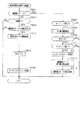
次に、通常処理の流れを図13のフローチャートを参照しながら説明する。通常処理は電源投入に伴い起動されるメイン処理が実行された後に開始される処理であり、通常処理では遊技の主要な処理が実行される。その概要として、ステップS301〜S307の処理が4msec周期の定期処理として実行され、その残余時間でステップS309,S310のカウンタ更新処理が実行される構成となっている。
<Normal processing>
Next, the flow of normal processing will be described with reference to the flowchart of FIG. The normal process is a process that is started after the main process that is activated when the power is turned on, and the main process of the game is executed in the normal process. As an outline, the processing of steps S301 to S307 is executed as a periodic processing with a period of 4 msec, and the counter update processing of steps S309 and S310 is executed with the remaining time.
通常処理において、ステップS301では、タイマ割込み処理又は前回の通常処理で設定したコマンド等の出力データをサブ側の各制御装置に送信する。具体的には、賞球コマンドの有無を判定し、賞球コマンドが設定されていればそれを払出制御装置90に対して送信する。また、変動用コマンド、種別コマンド、変動終了コマンド等の演出用コマンドが設定されている場合にはそれを音声ランプ制御装置76に対して送信する。
In the normal process, in step S301, output data such as a command set in the timer interrupt process or the previous normal process is transmitted to each control device on the sub side. Specifically, the presence or absence of a prize ball command is determined, and if a prize ball command is set, it is transmitted to the
続くステップS302では、変動種別カウンタCSの更新を実行する。具体的には、変動種別カウンタCSを1インクリメントすると共に、カウンタ値が最大値に達した際にはカウンタ値を0にクリアする。そして、変動種別カウンタCSの更新値を、RAM84の該当するバッファ領域に格納する。
In the subsequent step S302, the variation type counter CS is updated. Specifically, the variation type counter CS is incremented by 1, and the counter value is cleared to 0 when the counter value reaches the maximum value. Then, the update value of the variation type counter CS is stored in the corresponding buffer area of the
続くステップS303では、各遊技回における遊技を制御するための遊技回制御処理を実行する。この遊技回制御処理では、大当たり判定、図柄表示装置31による図柄の変動表示の設定、及びメイン表示部33の表示制御などを行う。遊技回制御処理の詳細は後述する。
In subsequent step S303, a game number control process for controlling a game in each game time is executed. In this game times control process, jackpot determination, symbol variable display setting by the
その後、ステップS304では、遊技状態を移行させるための遊技状態移行処理を実行する。詳細は後述するが、この遊技状態移行処理により、遊技状態が開閉実行モード、高確率モードなどに移行する。 Thereafter, in step S304, a game state transition process for shifting the game state is executed. Although details will be described later, the gaming state shifts to an opening / closing execution mode, a high probability mode, and the like by this gaming state transition processing.
続くステップS305では、下作動口24に設けられた電動役物24aを駆動制御するための電役サポート用処理を実行する。この電役サポート用処理では、RAM84の電役保留エリア84cに格納されている情報を用いて電動役物24aを開放状態とするか否かの判定、電動役物24aの開閉処理及び役物用表示部34の表示制御などを行う。
In a succeeding step S305, an electric combination support process for driving and controlling the electric combination 24a provided in the lower working
その後、ステップS306では、遊技球発射制御処理を実行する。遊技球発射制御処理では、電源及び発射制御装置100から発射許可信号を入力していることを条件として、所定期間(例えば、0.6sec)に1回、遊技球発射機構101のソレノイドを励磁する。これにより、遊技球が遊技領域に向けて打ち出される。
Thereafter, in step S306, a game ball launch control process is executed. In the game ball launch control process, the solenoid of the game
続くステップS307では、RAM84に停電フラグが格納されているか否かを判定する。停電フラグは、停電監視基板85において停電の発生が確認され当該停電監視基板85からMPU82のNMI端子に停電信号が入力されることにより格納され、次回のメイン処理にて消去されるフラグである。
In a succeeding step S307, it is determined whether or not a power failure flag is stored in the
停電フラグが格納されていない場合は、繰り返し実行される複数の処理の最後の処理が終了したこととなるので、ステップS308にて次の通常処理の実行タイミングに至ったか否か、すなわち前回の通常処理の開始から所定時間(本実施形態では4msec)が経過したか否かを判定する。そして、次の通常処理の実行タイミングに至るまでの残余時間内において、乱数初期値カウンタCINI及び変動種別カウンタCSの更新を繰り返し実行する。 When the power failure flag is not stored, the last process of the plurality of processes that are repeatedly executed is completed, so whether or not the execution timing of the next normal process is reached in step S308, that is, the previous normal process It is determined whether a predetermined time (4 msec in this embodiment) has elapsed since the start of the process. Then, the random number initial value counter CINI and the variation type counter CS are repeatedly updated within the remaining time until the next normal processing execution timing.
つまり、ステップS309では、乱数初期値カウンタCINIの更新を実行する。具体的には、乱数初期値カウンタCINIを1加算すると共に、そのカウンタ値が最大値に達した際0にクリアする。そして、乱数初期値カウンタCINIの更新値を、RAM84の該当するエリアに格納する。また、ステップS310では、変動種別カウンタCSの更新を実行する。具体的には、変動種別カウンタCSを1加算すると共に、それらのカウンタ値が最大値に達した際0にクリアする。そして、変動種別カウンタCSの更新値を、RAM84の該当するエリアに格納する。
That is, in step S309, the random number initial value counter CINI is updated. Specifically, the random number initial value counter CINI is incremented by 1 and cleared to 0 when the counter value reaches the maximum value. Then, the updated value of the random number initial value counter CINI is stored in the corresponding area of the
一方、ステップS307にて、停電フラグが格納されていると判定した場合は、電源遮断が発生したことになるので、ステップS311以降の電断時処理を実行する。つまり、ステップS311では、タイマ割込み処理の発生を禁止し、その後、ステップS312にてRAM判定値を算出、保存し、ステップS313にてRAM84のアクセスを禁止した後に、電源が完全に遮断して処理が実行できなくなるまで無限ループを継続する。
On the other hand, if it is determined in step S307 that the power failure flag is stored, the power interruption has occurred, so the power interruption processing from step S311 is executed. That is, in step S311, the generation of the timer interrupt process is prohibited, and after that, the RAM determination value is calculated and stored in step S312, and after the access to the
<遊技回制御処理>
次に、ステップS303の遊技回制御処理を図14のフローチャートを参照しながら説明する。
<Game times control processing>
Next, the game times control process of step S303 will be described with reference to the flowchart of FIG.
遊技回制御処理では、先ずステップS401にて、開閉実行モード中か否かを判定する。具体的には、RAM84の各種フラグ格納エリア84eにおける開閉実行モードフラグ格納エリアに開閉実行モードフラグが格納されているか否かを判定する。当該開閉実行モードフラグは、後述する遊技状態移行処理にて遊技状態を開閉実行モードに移行させる場合に格納され、同じく遊技状態移行処理にて開閉実行モードを終了させる場合に消去される。
In the game times control process, first, in step S401, it is determined whether or not the opening / closing execution mode is in effect. Specifically, it is determined whether an opening / closing execution mode flag is stored in the opening / closing execution mode flag storage area in the various
開閉実行モード中である場合には、ステップS402以降の処理、すなわちステップS403〜ステップS405の遊技回開始用処理及びステップS406〜ステップS409の遊技回進行用処理のいずれも実行することなく、本遊技回制御処理を終了する。つまり、開閉実行モード中である場合には、作動口23,24への入賞が発生しているか否かに関係なく、遊技回が開始されることはない。
When in the open / close execution mode, the game is executed without executing any of the processes after step S402, that is, the game times starting process in steps S403 to S405 and the game times progressing process in steps S406 to S409. End control processing. In other words, in the open / close execution mode, the game times are not started regardless of whether or not a winning for the
開閉実行モード中でない場合には、ステップS402にて、メイン表示部33が変動表示中であるか否かを判定する。この判定は、RAM84の各種フラグ格納エリア84eにおける変動表示中フラグ格納エリアに変動表示中フラグが格納されているか否かを判定することにより行う。変動表示中フラグは、メイン表示部33において変動表示を開始させる場合に格納され、その変動表示が終了する場合に消去される。
If it is not in the opening / closing execution mode, it is determined in step S402 whether or not the
メイン表示部33が変動表示中でない場合には、ステップS403〜ステップS405の遊技回開始用処理に進む。遊技回開始用処理では、先ずステップS403にて、保留球格納エリア84bの保留数記憶エリアNAを参照し、保留記憶されている保留情報の数である始動保留記憶数Nが「0」か否かを判定する。始動保留記憶数Nが「0」である場合とは、保留球格納エリア84bに保留情報が記憶されていないことを意味する。したがって、そのまま本遊技回制御処理を終了する。始動保留記憶数Nが「0」でない場合には、ステップS404にてデータ設定処理を実行する。
If the
データ設定処理では先ず始動保留記憶数Nを1減算する。また、保留球格納エリア84bにおける保留用エリアREの第1保留エリアRE1に格納されているデータを実行エリアAEに移動する。その後、保留用エリアREの各保留エリアRE1〜RE4に格納されたデータをシフトさせる処理を実行する。このデータシフト処理は、第1保留エリアRE1〜第4保留エリアRE4に格納されているデータを下位エリア側に順にシフトさせる処理であって、第1保留エリアRE1のデータをクリアするとともに、第2保留エリアRE2→第1保留エリアRE1、第3保留エリアRE3→第2保留エリアRE2、第4保留エリアRE4→第3保留エリアRE3といった具合に各エリア内のデータがシフトされる。
In the data setting process, first, the start pending storage number N is decremented by one. Further, the data stored in the first holding area RE1 of the holding area RE in the holding
なお、データ設定処理では、保留情報のシフトが行われたことを音声ランプ制御装置76に認識させて第1保留ランプ部35における表示を保留個数の減少に対応させて変更させるための処理を実行する。
In the data setting process, the voice
データ設定処理を実行した後は、ステップS405にて変動開始処理を実行した後に、本遊技回制御処理を終了する。変動開始処理では今回の遊技回が大当たり当選か否かの当否判定を行うとともに、当該遊技回の変動表示態様を決定する処理を実行する。 After executing the data setting process, the game start control process is terminated after the change start process is executed in step S405. In the variation start process, a determination is made as to whether or not the current game time is a big win, and a process for determining a variation display mode of the game time is executed.
具体的には、先ず当否抽選モードを把握し、把握された抽選モードに対応した当否テーブルを参照して、実行エリアAEに格納された情報のうち当否判定用の情報、すなわち大当たり乱数カウンタC1に係る値が大当たり数値情報と一致しているか否かを判定する。 Specifically, first, the winning / losing lottery mode is grasped, and by referring to the winning / failing table corresponding to the grasped lottery mode, the information for judging the success / failure among the information stored in the execution area AE, that is, the big hit random number counter C1. It is determined whether the value matches the jackpot value information.
一致している場合には、実行エリアAEに格納されている大当たり種別カウンタC2の値を取得し、振分テーブルを参照して、上記取得した大当たり種別カウンタC2の値がいずれの大当たり種別に対応しているのかを特定する。 If they match, the value of the jackpot type counter C2 stored in the execution area AE is acquired, and the value of the acquired jackpot type counter C2 corresponds to any jackpot type by referring to the distribution table. Identify what you are doing.
その後、これらの把握結果(大当たりであるか否か、大当たりである場合にはその種別)に基づいて、メイン表示部33に最終的に停止表示させる絵柄の態様を決定し、その決定された態様に対応した情報をRAM84に記憶する。今回の遊技回の当否判定結果が、確変大当たり結果又は通常大当たり結果である場合には、MPU82にてこれらの結果であることを特定するための情報をRAM84に格納する。具体的には、確変大当たり結果である場合にはRAM84に確変フラグをセットし、通常大当たり結果である場合にはRAM84に通常大当たりフラグをセットする。
After that, based on these grasping results (whether or not it is a jackpot or its type if it is a jackpot), the mode of the picture to be finally stopped and displayed on the
そして、上記把握結果に基づいて、メイン表示部33の変動表示時間を決定する。この場合、リーチ表示を行なうか否かを判定し、リーチ表示を行なうと判定した場合には、ROM83の変動表示時間テーブル記憶エリア83cに記憶されているリーチ発生用変動表示時間テーブルを参照して、今回の変動種別カウンタCSの値に対応した変動表示時間情報を取得し、その変動表示時間情報をRAM84の各種カウンタエリア84dに設けられた変動表示時間カウンタ(変動表示時間計測手段)にセットする。一方、リーチ表示が発生しないと判定した場合には、変動表示時間テーブル記憶エリア83cに記憶されているリーチ非発生用変動表示時間テーブルを参照して、今回の変動種別カウンタCSの値に対応した変動表示時間を取得し、その変動表示時間情報を上記変動表示時間カウンタにセットする。
And based on the said grasping | ascertainment result, the fluctuation | variation display time of the
その後、変動用コマンド及び種別コマンドを設定し、メイン表示部33において絵柄の変動表示を開始させた後、本遊技回制御処理を終了する。変動用コマンドには、リーチ発生の有無の情報及び変動表示時間の情報が含まれる。また、種別コマンドには、遊技結果の情報が含まれる。つまり、種別コマンドには、遊技結果の情報として、確変大当たり結果の情報、通常大当たり結果の情報、外れ結果の情報などが含まれる。
Thereafter, a variation command and a type command are set, and after the variation display of the pattern is started on the
変動用コマンド及び種別コマンドは、通常処理(図13)におけるステップS301にて、音声ランプ制御装置76に送信される。音声ランプ制御装置76では、受信した変動用コマンド及び種別コマンドに基づいて、その遊技回における表示ランプ部63の発光パターンやスピーカ部64からの音の出力パターンを決定し、その決定した演出の内容が実行されるように表示ランプ部63及びスピーカ部64を制御する。また、音声ランプ制御装置76は、上記変動用コマンド及び種別コマンドをその情報形態を維持したまま表示制御装置110に送信する。表示制御装置110では、受信した変動用コマンド及び種別コマンドに基づいて、その遊技回における図柄表示装置31での変動表示パターンを決定し、その変動表示パターンが実行されるように図柄表示装置31を表示制御する。
The variation command and the type command are transmitted to the sound
メイン表示部33が変動表示中である場合には、ステップS406〜ステップS409の遊技回進行用処理を実行する。
When the
遊技回進行用処理では、先ずステップS406にて、今回の遊技回の変動表示時間が経過したか否かを判定する。具体的には、RAM84の変動表示時間カウンタに格納されている変動表示時間情報の値が「0」となったか否かを判定する。当該変動表示時間情報の値は、上述したように、変動開始処理(ステップS405)においてセットされる。また、このセットされた変動表示時間情報の値は、タイマ割込み処理(図11)が起動される度に1減算される。
In the game times progression process, first, in step S406, it is determined whether or not the current game times change display time has elapsed. Specifically, it is determined whether or not the value of the variable display time information stored in the variable display time counter of the
変動表示時間が経過していない場合には、ステップS407にて変動表示用処理を実行する。変動表示用処理では、メイン表示部33における表示態様を変更する。その後、本遊技回制御処理を終了する。
If the variable display time has not elapsed, the variable display process is executed in step S407. In the variable display process, the display mode on the
変動表示時間が経過している場合には、ステップS408にて変動終了処理を実行する。変動終了処理では、上記ステップS405の処理において決定した停止結果がメイン表示部33にて表示されるように当該メイン表示部33を表示制御する。
If the fluctuation display time has elapsed, a fluctuation end process is executed in step S408. In the change end process, the
続くステップS409では、変動終了コマンドを設定する。この設定された変動終了コマンドは、通常処理(図13)におけるステップS301にて、音声ランプ制御装置76に送信される。音声ランプ制御装置76では、受信した変動終了コマンドをその情報形態を維持したまま表示制御装置110に送信する。表示制御装置110では、当該変動終了コマンドを受信することにより、その遊技回における最終停止図柄の組み合わせを確定表示(最終停止表示)させる。その後、本遊技回制御処理を終了する。
In the subsequent step S409, a change end command is set. The set change end command is transmitted to the sound
<遊技状態移行処理>
次に、ステップS304の遊技状態移行処理を図15のフローチャートを参照して説明する。
<Game state transition processing>
Next, the gaming state transition processing in step S304 will be described with reference to the flowchart in FIG.
先ず、ステップS501では、開閉実行モード中か否かを判定する。開閉実行モード中でない場合にはステップS502に進み、1の遊技回のメイン表示部33における絵柄の変動表示が終了したタイミングか否かを判定する。変動表示が終了したタイミングでない場合には、そのまま本遊技状態移行処理を終了する。
First, in step S501, it is determined whether or not the opening / closing execution mode is in effect. If it is not in the opening / closing execution mode, the process proceeds to step S502, and it is determined whether or not it is the timing when the variation display of the pattern on the
変動表示が終了したタイミングである場合には、ステップS503にて、今回の遊技回の遊技結果が開閉実行モードへの移行に対応したものであるか否かを判定する。具体的には、RAM84に、確変フラグ又は通常大当たりフラグのいずれかが格納されているか否かを判定する。上記各フラグのいずれもが格納されていない場合には、そのまま本遊技状態移行処理を終了する。
If it is the timing when the variable display is finished, it is determined in step S503 whether or not the game result of the current game time corresponds to the transition to the opening / closing execution mode. Specifically, it is determined whether or not either the probability variation flag or the normal jackpot flag is stored in the
上記各フラグのいずれかが格納されている場合には、ステップ504にて開閉実行モードの開始処理を実行する。当該開始処理では、開閉実行モードのオープニング用に可変入賞装置22の開閉扉22bの開放を開始することなく待機するためのオープニング用待機時間(開始用待機期間)を設定する。具体的には、RAM84の各種カウンタエリア84dに設けられた待機時間用カウンタエリアに、ROM83に予め記憶されているオープニング用の待機時間情報をセットする。
If any one of the above flags is stored, an opening / closing execution mode start process is executed in
続くステップS505では、RAM84の各種カウンタエリア84dに設けられたラウンドカウンタRCに、「15」をセットする。ラウンドカウンタRCは、開閉扉22bが開放された回数をカウントするためのカウンタエリアである。
In a succeeding step S505, “15” is set in the round counter RC provided in the
ステップS505の処理を実行した後は、ステップS506にてオープニングコマンドを設定した後に、本遊技状態移行処理を終了する。ステップS506にて設定されたオープニングコマンドは、通常処理(図13)におけるステップS301にて、音声ランプ制御装置76に送信される。
After executing the process of step S505, after setting the opening command in step S506, the gaming state transition process is terminated. The opening command set in step S506 is transmitted to the sound
音声ランプ制御装置76では、受信したオープニングコマンドに基づいて、開閉実行モードにおける表示ランプ部63の発光パターンやスピーカ部64からの音の出力パターンを決定し、その決定した演出の内容が実行されるように表示ランプ部63やスピーカ部64を制御する。また、音声ランプ制御装置76は、上記オープニングコマンドをその情報形態を維持したまま表示制御装置110に送信する。表示制御装置110では、受信したオープニングコマンドに基づいて、開閉実行モードに対応した演出を図柄表示装置31において開始させる。
The sound
一方、開閉実行モード中である場合(ステップS501:YES)には、ステップS507に進む。ステップS507では、オープニング用の待機時間が経過したか否かを判定する。オープニング用の待機時間が経過していない場合には、そのまま本遊技状態移行処理を終了する。オープニング用の待機時間が経過している場合には、ステップS508にて大入賞口開閉処理を実行する。ここで、大入賞口開閉処理について、図16のフローチャートを参照しながら説明する。 On the other hand, when it is in the opening / closing execution mode (step S501: YES), the process proceeds to step S507. In step S507, it is determined whether or not the opening standby time has elapsed. If the opening standby time has not elapsed, the gaming state transition process is terminated. When the waiting time for the opening has elapsed, a big winning opening / closing process is executed in step S508. Here, the special winning opening / closing process will be described with reference to the flowchart of FIG.
先ず、ステップS601にて開閉扉22bを開放中であるか否かを判定する。具体的には、可変入賞駆動部22dの駆動状態に基づいてかかる判定を行う。開閉扉22bを開放中でない場合には、ステップS602にてラウンドカウンタRCの値が「0」か否かを判定するとともに、ステップS603にてRAM84の各種カウンタエリア84dに設けられたタイマTの値が「0」か否かを判定する。
First, in step S601, it is determined whether or not the open /
ラウンドカウンタRCの値が「0」である場合又はタイマTの値が「0」でない場合には、そのまま本大入賞口開閉処理を終了する。一方、ラウンドカウンタRCの値が「0」でなく且つタイマTの値が「0」である場合には、ステップS604に進み、開閉扉22bを開放すべく可変入賞駆動部22dを駆動状態とする。具体的には、MPU82から出力される第1制御信号SG1をHIからLOWにする。これにより、ソレノイド161が駆動し、開閉扉22bが開放状態となる。また、ステップS604では、第2制御信号SG2をLOWからHIに設定する処理を実行する。これにより、LED22cが発光する。
When the value of the round counter RC is “0” or when the value of the timer T is not “0”, the big prize opening / closing process is ended as it is. On the other hand, if the value of the round counter RC is not “0” and the value of the timer T is “0”, the process proceeds to step S604, and the variable winning
ここで、第1制御信号SG1は通常の遊技状態においては大入賞口22aが開放されないようにHI信号に設定されている。つまり、第1制御信号SG1は通常状態においてHI信号であって大入賞口22aを解放する場合にのみLOW信号となる信号である。
Here, the first control signal SG1 is set to the HI signal so that the special winning
一方、第2制御信号SG2は通常の遊技状態においてはLED22cが発光しないようにLOW信号に設定されている。つまり、第2制御信号SG2は通常状態においてLOW信号であってLED22cを発光させる場合にのみHI信号となる信号である。
On the other hand, the second control signal SG2 is set to a LOW signal so that the
続くステップS605では、タイマTに、「15000」(すなわち30sec)をセットする。ここでセットされたカウント値は、タイマ割込み処理(図11)が起動される都度、すなわち2msec周期で1減算される。また、大入賞口22aへの遊技球の入賞数をカウントするために、RAM84の各種カウンタエリア84dに設けられた入賞カウンタエリアPCに、「10」をセットする。
In a succeeding step S605, "15000" (that is, 30 sec) is set in the timer T. The count value set here is decremented by 1 every time the timer interrupt process (FIG. 11) is started, that is, every 2 msec. In addition, “10” is set in the winning counter area PC provided in the
その後、ステップS606にて開放コマンドを設定し、本大入賞口開閉処理を終了する。この設定された開放コマンドは、通常処理(図13)におけるステップS301にて、音声ランプ制御装置76に送信される。音声ランプ制御装置76は、受信した開放コマンドに基づいて、表示ランプ部63やスピーカ部64における演出内容を変更する。また、音声ランプ制御装置76は、上記開放コマンドをその情報形態を維持したまま表示制御装置110に送信する。表示制御装置110では、受信した開放コマンドに基づいて、図柄表示装置31における開閉実行モード用の演出を切り換える。当該表示制御の具体的な内容については、後に説明する。
Thereafter, an opening command is set in step S606, and the main prize winning opening / closing process is terminated. The set release command is transmitted to the sound
一方、開閉扉22bが開放中である場合(ステップS601:YES)には、ステップS607に進みタイマTの値が「0」か否かを判定する。タイマTの値が「0」でない場合、ステップS608にて大入賞口22aに遊技球が入賞したか否かを、可変入賞装置22に対応したカウント用入賞検知センサ53bの検知状態により判定する。入賞が発生していない場合には、そのまま本大入賞口開閉処理を終了する。一方、入賞が発生している場合には、ステップS609にて入賞カウンタエリアPCの値を1減算した後にステップS610にて入賞カウンタエリアPCの値が「0」か否かを判定し、「0」でない場合にはそのまま本大入賞口開閉処理を終了する。
On the other hand, if the open /
ステップS607にてタイマTの値が「0」の場合、又はステップS610にて入賞カウンタエリアPCの値が「0」の場合には、大入賞口閉鎖条件が成立したことを意味する。かかる場合にはステップS611にて開閉扉22bを閉鎖すべく可変入賞駆動部22dを非駆動状態とする。具体的には、第1制御信号SG1をHIからLOWに設定する処理を実行する。これにより、ソレノイド161に対する電圧印加が停止する。
If the value of the timer T is “0” in step S607 or if the value of the winning counter area PC is “0” in step S610, it means that the special winning opening closing condition is established. In such a case, in step S611, the variable winning
また、ステップS611では、LED22cの発光を停止する処理を実行する。具体的には、第2制御信号SG2をLOWからHIに設定する。これにより、LED22cに対する電圧印加が停止し、LED22cの発光が停止する。
In step S611, a process for stopping the light emission of the
続くステップS612ではラウンドカウンタRCの値を1減算し、ステップS613にてラウンドカウンタRCの値が「0」か否かを判定する。ラウンドカウンタRCの値が「0」である場合には、そのまま本大入賞口開閉処理を終了する。ラウンドカウンタRCの値が「0」でない場合にはステップS614にてタイマTに「1000」(すなわち2sec)をセットする。その後、ステップS615にて閉鎖コマンドを設定し、本大入賞口開閉処理を終了する。 In subsequent step S612, 1 is subtracted from the value of the round counter RC. In step S613, it is determined whether or not the value of the round counter RC is “0”. When the value of the round counter RC is “0”, the main prize winning opening / closing process is finished as it is. If the value of the round counter RC is not “0”, “1000” (that is, 2 sec) is set to the timer T in step S614. Thereafter, a closing command is set in step S615, and the main prize winning opening / closing process is terminated.
この設定された閉鎖コマンドは、通常処理(図13)におけるステップS301にて、音声ランプ制御装置76に送信される。音声ランプ制御装置76は、受信した閉鎖コマンドに基づいて、1ラウンド分の開閉扉22bの開放が終了したことを特定する。
The set closing command is transmitted to the sound
遊技状態移行処理(図15)の説明に戻り、ステップS508にて大入賞口開閉処理を実行した後は、ステップS509にてラウンドカウンタRCの値が「0」か否かを判定するとともに、ステップS510にてエンディング用の待機時間が経過したか否かを判定する。ここで、本パチンコ機10では、開閉実行モードの終了に際しては図柄表示装置31などにてエンディング用の演出が実行されるように構成されており、エンディング用の待機時間とは当該エンディング用の演出が終了するまで主制御装置73にて次の遊技回の開始を待機するための期間である。
Returning to the description of the gaming state transition process (FIG. 15), after executing the big prize opening / closing process in step S508, it is determined in step S509 whether or not the value of the round counter RC is “0”. In S510, it is determined whether or not the ending standby time has elapsed. Here, the
ラウンドカウンタRCの値が「0」でない場合又はエンディング用の待機時間が経過していない場合には、そのまま本遊技状態移行処理を終了する。一方、ラウンドカウンタRCの値が「0」であり、且つエンディング用の待機時間が経過している場合には、ステップS511にて、エンディングコマンドを設定する。当該エンディングコマンドは、通常処理(図13)におけるステップS301にて、音声ランプ制御装置76に送信される。音声ランプ制御装置76は、受信したエンディングコマンドに基づいて、表示ランプ部63やスピーカ部64における開閉実行モード用の演出を終了させる。また、音声ランプ制御装置76は、上記エンディングコマンドをその情報形態を維持したまま表示制御装置110に送信する。表示制御装置110では、受信したエンディングコマンドに基づいて、図柄表示装置31における開閉実行モード用の演出を終了させる。
When the value of the round counter RC is not “0” or when the ending waiting time has not elapsed, the gaming state transition process is terminated as it is. On the other hand, if the value of the round counter RC is “0” and the waiting time for ending has elapsed, an ending command is set in step S511. The ending command is transmitted to the sound
続くステップS512では、開閉実行モード終了時の移行処理を実行する。当該移行処理では、RAM84に確変フラグ又は通常大当たりフラグのいずれが格納されているか否かを判定する。そして、確変フラグが格納されている場合には、当否抽選モードを高確率モードに設定し、通常大当たりフラグが格納されている場合には、当否抽選モードを低確率モードに設定する。
In the subsequent step S512, a transition process at the end of the opening / closing execution mode is executed. In the transition process, it is determined whether the probability change flag or the normal jackpot flag is stored in the
その後、ステップS513にて、開閉実行モードの終了処理を実行した後に、本遊技状態移行処理を終了する。開閉実行モードの終了処理では、確変フラグ、通常大当たりフラグのいずれかが格納されている場合には、それを消去するとともに、既に格納されていない場合にはその状態を維持する。 Thereafter, in step S513, after executing the opening / closing execution mode end processing, the gaming state transition processing ends. In the opening / closing execution mode end process, if either the probability variation flag or the normal jackpot flag is stored, it is deleted, and if it is not already stored, the state is maintained.
以上詳述した本実施形態によれば以下の優れた効果を奏する。 According to the embodiment described in detail above, the following excellent effects are obtained.
通常LOW信号であって磁気を検知した場合にHIとなる検知信号SG0を伝送する検知信号線LN0が接続される信号ピンPS0を電源ピンPE1よりもグランドピンPG1寄りの位置に配置した。これにより信号ピンPS0が電源ピンPE1に対して短絡しにくくなるため、上記短絡による磁気検知センサ38の誤検知を抑制することができる。
A signal pin PS0 to which a detection signal line LN0 that transmits a detection signal SG0 that is a HI signal when a magnetic signal is detected is connected is arranged closer to the ground pin PG1 than the power supply pin PE1. As a result, the signal pin PS0 is less likely to be short-circuited to the power supply pin PE1, so that erroneous detection of the
磁気検知センサ38がONとなっている状態が所定の期間(0.1sec)に亘って継続した場合に、異常報知が行われる構成とした。これにより、ノイズによる瞬間的な反応によって磁気検知センサ38の誤検知し、誤って異常報知が行われることを抑制することができる。
When the state in which the
ここで、電源線ELN1及びグランド線GLN1を伝送する電圧は定常的であるため、一旦電源ピンPE1が信号ピンPS0と短絡すると、検知信号線LN0にて伝送される検知信号SG0は常時HI又はLOWとなる。このため、上記所定の期間を設けた場合であっても、短絡による誤動作を抑制することができない。これに対して、電源ピンPE1と隣り合わないように信号ピンPS0を配置することによって、上記所定の期間を設けることでは解決することができない磁気検知センサ38の誤動作を抑制することができる。
Here, since the voltage transmitted through the power supply line ELN1 and the ground line GLN1 is stationary, once the power supply pin PE1 is short-circuited to the signal pin PS0, the detection signal SG0 transmitted through the detection signal line LN0 is always HI or LOW. It becomes. For this reason, even if it is a case where the said predetermined period is provided, the malfunctioning by a short circuit cannot be suppressed. On the other hand, by arranging the signal pin PS0 so as not to be adjacent to the power supply pin PE1, malfunction of the
電源ピンPE1とグランドピンPG1とを互いに離間させて配置した。具体的には、ピン配列領域122の一端側に電源ピンPE1を配置し、他端側にグランドピンPG1を配置した。そして、電源ピンPE1とグランドピンPG1との間に、各種ピン(信号ピンPS0やダミーピンPD)を配置した。これにより、電源ピンPE1とグランドピンPG1とが短絡しにくくなっている。よって、電源ピンPE1とグランドピンPG1とが短絡することによって大電流が流れ、各種機器が破壊されるという不都合を回避することができる。電源ピンPE2及びグランドピンPG2についても同様である。
The power supply pin PE1 and the ground pin PG1 are arranged apart from each other. Specifically, the power supply pin PE1 is disposed on one end side of the
この場合(電源ピンPE1,PE2及びグランドピンPG1,PG2を離間して配置した場合)、電源ピンPE1,PE2に対して混入されたノイズがグランドピンPG1,PG2に逃げにくいため、グランドピンPG1,PG2と電源ピンPE1,PE2とが隣同士に配置されている状況と比較して、電源ピンPE1,PE2にノイズが混入され易い。 In this case (when the power supply pins PE1 and PE2 and the ground pins PG1 and PG2 are arranged apart from each other), noise mixed into the power supply pins PE1 and PE2 is difficult to escape to the ground pins PG1 and PG2. Compared with the situation where PG2 and power supply pins PE1, PE2 are arranged next to each other, noise is likely to be mixed into power supply pins PE1, PE2.
これに対して、基板側コネクタSCN3においては、信号ピンPS0と電源ピンPE1との距離が信号ピンPS0とグランドピンPG1との距離と比較して大きくなっている。これにより、電源ピンPE1のノイズが信号ピンPS0に対して影響しにくくなるため、信号ピンPS0を介して伝送される検知信号SG0の信頼性を確保することができる。 On the other hand, in the board-side connector SCN3, the distance between the signal pin PS0 and the power supply pin PE1 is larger than the distance between the signal pin PS0 and the ground pin PG1. Thereby, since the noise of the power supply pin PE1 is less likely to affect the signal pin PS0, the reliability of the detection signal SG0 transmitted through the signal pin PS0 can be ensured.
また、基板側コネクタSCN6においては、電源ピンPE2側に第1制御信号SG1を伝送する第1信号ピンPS1を配置することで、仮に電源ピンPE2及び電源線ELN2に対してノイズが混入した場合には第1制御信号SG1が相対的にHIになり易く、開閉用回路151の誤動作が抑制されている。以上のことから、電源ピンPE2とグランドピンPG2とを離間させて配置することによって生じ得る不都合が回避されている。
Further, in the board-side connector SCN6, when the first signal pin PS1 for transmitting the first control signal SG1 is arranged on the power supply pin PE2 side, if noise is mixed into the power supply pin PE2 and the power supply line ELN2. The first control signal SG1 tends to be relatively HI, and the malfunction of the
電源線ELN2及びグランド線GLN2を介して動作電力が供給されている状況において第1制御信号SG1がLOWである場合に開閉扉22bを開放させる開閉用回路151を設けるとともに、第2制御信号SG2がHIである場合にLED22cを発光させるLED用回路152を設けた。そして、第1制御信号SG1を伝送するのに用いられる第1信号ピンPS1を電源ピンPE2寄りに配置し、第2制御信号SG2を伝送するのに用いられる第2信号ピンPS2をグランドピンPG2寄りに配置した。これにより、仮に各信号ピンPS1,PS2と対応するピン(第1信号ピンPS1にあっては電源ピンPE2、第2信号ピンPS2にあってはグランドピンPG2)とが短絡した場合であっても、各回路151,152は動作しない。これにより、上記短絡による各種機器の誤動作を抑制することができる。
In a situation where operating power is supplied via the power supply line ELN2 and the ground line GLN2, when the first control signal SG1 is LOW, an opening /
磁気検知センサ38及び可変入賞駆動部22dを直流駆動に設定した。これにより、主制御基板81に入力される動作電力を流用することができ、構成の簡素化を図ることができる。
The
また、直流電圧を伝送する電源線ELN1,ELN2から生じるノイズは、交流電圧を伝送する場合よりも小さい。これにより、電源線ELN1,ELN2から生じるノイズによる各種機器の誤動作を抑制することができる。 Further, noise generated from the power supply lines ELN1 and ELN2 that transmit a DC voltage is smaller than that when an AC voltage is transmitted. Thereby, malfunctions of various devices due to noise generated from the power supply lines ELN1, ELN2 can be suppressed.
<第2実施形態>
本実施形態では、可変入賞駆動部22dの構成が第1実施形態と異なるため、その異なる点について図17を用いて説明する。図17は、可変入賞駆動部22dの回路図である。なお、第1実施形態と同一の構成については同一の符号を付すとともに、その詳細な説明を省略する。
Second Embodiment
In the present embodiment, since the configuration of the variable
第1実施形態では、LED22c及びLED用回路152が設けられていたが、本実施形態ではこれらが削除されている。そして、ソレノイド161は第1制御信号SG1及び第2制御信号SG2に基づいて動作するように構成されている。
In the first embodiment, the
具体的には、本実施形態の開閉用回路200は、ソレノイド201と、当該ソレノイド201に対する電圧制御を行うp型MOSFET202及びn型MOSFET203と、を備えている。ソレノイド201及びp型MOSFET202の構成については上記第1実施形態の対応する構成と同様であるため、説明を省略する。
Specifically, the open /
n型MOSFET203は、ソレノイド201とグランド線GLN2との間に配置されており、具体的にはドレインがソレノイド201に接続されており、ソースがグランド線GLN2に対して接続されている。n型MOSFET203のゲートには、第2信号線LN2が接続されている。
The n-
かかる構成によれば、(1)第1信号線LN1を介してp型MOSFET202に対して入力される信号がLOWであり、且つ(2)第2信号線LN2を介してn型MOSFET203に対して入力される信号がHIである場合に、ソレノイド201が駆動し、開閉扉22bが開放される。このため、仮に第1信号ピンPS1と第2信号ピンPS2とが短絡した場合であっても、ソレノイド201は動作しないようになっている。よって、両信号ピンPS1,PS2の短絡によるソレノイド201の誤動作を抑制することができる。すなわち、ソレノイド201への電圧印加を制御する信号として第1制御信号SG1と第2制御信号SG2とを設け、第1制御信号SG1がHIであり且つ第2制御信号SG2が第1制御信号SG1とは逆のLOWである場合にソレノイド201に対して電圧が印加されるようにすることで、各信号ピンPS1,PS2と、それの隣に配置されている電源ピンPE2又はグランドピンPG2との短絡による誤動作を抑制しつつ、信号ピンPS1,PS2同士の短絡による誤動作を抑制することができる。
According to such a configuration, (1) the signal input to the p-
<その他の実施形態>
なお、上述した実施の形態の記載内容に限定されず、本発明の趣旨を逸脱しない範囲内で種々の変形改良が可能である。例えば以下のように変更してもよい。ちなみに、以下の別形態の構成を、上記実施の形態の構成に対して、個別に適用してもよく、組み合わせて適用してもよい。
<Other embodiments>
In addition, it is not limited to the description content of embodiment mentioned above, A various deformation | transformation improvement is possible within the range which does not deviate from the meaning of this invention. For example, you may change as follows. Incidentally, the configuration of another embodiment described below may be applied individually or in combination to the configuration of the above embodiment.
(1)各実施形態では、磁気検知センサ38は磁気を検知した場合に検知信号SG0がLOW信号からHI信号となる構成としたが、これに限られず、例えば磁気を検知した場合に検知信号SG0がHI信号からLOW信号となるように構成してもよい。この場合、信号ピンPS0をグランドピンPG1よりも電源ピンPE1寄りに設けることによって、すなわち信号ピンPS0とダミーピンPDとの位置を逆にすることによって上記第1実施形態等で説明した効果を奏することができる。
(1) In each embodiment, the
(2)第1実施形態では、開閉用回路151をLOWアクティブ回路として設定し、LED用回路152をHIアクティブ回路として設定したが、逆に設定してもよい。この場合、第1信号ピンPS1と第2信号ピンPS2との位置を逆に設定する。これにより、第1実施形態にて説明した効果を得ることができる。
(2) In the first embodiment, the
なお、開閉用回路151をLOWアクティブ回路として設定し、LED用回路152をHIアクティブ回路とする構成としては、例えば開閉用回路151においてp型MOSFET162に代えてn型MOSFET163を設け、LED用回路152においてn型MOSFET163に代えてp型MOSFET162を設ける構成が考えられる。
As a configuration in which the
(3)可変入賞駆動部22dに対応する基板側コネクタSCN6等は4ピンを有していたが、これに代えて、図18(a)に示すように、8ピンを有する基板側コネクタSCN10を設けてもよい。この場合、各電源ピンPE2、第1信号ピンPS1、第2信号ピンPS2、グランドピンPG2の間にダミーピンPDを配置するとともに、電源ピンPE2側に第1信号ピンPS1を配置し、グランドピンPG2側に第2信号ピンPS2を配置するとよい。これにより、各ピンPE2,PG2,PS1,PS2間での短絡を生じにくくすることができるとともに、仮に短絡が生じた場合であっても、可変入賞駆動部22dの誤動作が生じにくい。
(3) The board-side connector SCN6 corresponding to the variable
また、基板側コネクタSCN3においては、信号ピンPS0とグランドピンPG1との間にダミーピンPDを設けてもよい。これにより、信号ピンPS0に対するグランドピンPG1の影響を低減することができるとともに、強制的に信号ピンPS0とグランドピンPG1とを短絡させて磁気検知センサ38の機能を停止させる不正行為を抑制することができる。
In the board-side connector SCN3, a dummy pin PD may be provided between the signal pin PS0 and the ground pin PG1. As a result, the influence of the ground pin PG1 on the signal pin PS0 can be reduced, and an illegal act of forcibly shorting the signal pin PS0 and the ground pin PG1 to stop the function of the
(4)上記各実施形態によれば、ピン配列領域142において各ピンPE2,PG2,PS1,PS2は等間隔に配置されていたが、これに限られず、例えば図18(b)に示すように、グランドピンPG2及び第2信号ピンPS2間の距離並びに電源ピンPE2及び第1信号ピンPS1間の距離が、第1信号ピンPS1及び第2信号ピンPS2間の距離よりも大きくなるように各ピンPE2,PG2,PS1,PS2の位置を設定する構成としてもよい。これにより、電源ピンPE2等と第1信号ピンPS1等の短絡をより抑制することができるとともに、各制御信号SG1,SG2に与える電源ピンPE2等の影響をより小さくすることができる。さらに、この場合、専用のコネクタとなるため、接続可能なコネクタが一義的に決まる。これにより、コネクタの接続ミスが低減され、接続作業の作業性の向上を図ることができる。
(4) According to each of the above embodiments, the pins PE2, PG2, PS1, and PS2 are arranged at equal intervals in the
(5)上記各実施形態によれば、ピン配列領域142の両端に電源ピンPE2及びグランドピンPG2を配置する構成としたが、これに限られず、例えば図18(c)に示すように、ピン配列領域142の両端に第1信号ピンPS1及び第2信号ピンPS2をそれぞれ配置し、これら信号ピンPS1,PS2の間に電源ピンPE2及びグランドピンPG2を配置する構成としてもよい。この場合、第1信号ピンPS1側に電源ピンPE2を配置し、第2信号ピンPS2側にグランドピンPG2を配置するとよい。さらに、電源ピンPE2とグランドピンPG2との短絡を抑制すべく、電源ピンPE2とグランドピンPG2との間に新たにダミーピンPDを設けるとよい。
(5) According to each of the above embodiments, the power pin PE2 and the ground pin PG2 are arranged at both ends of the
(6)上記各実施形態では、中継基板54を設け、当該中継基板54を介して主制御基板81と各種機器とを接続する構成としたが、これに限られず、各種機器の一部又は全部を直接接続する構成としてもよい。この場合、主制御基板81と各種機器とを接続するのに用いられるコネクタに対して本発明を適用することができる。
(6) In each of the above embodiments, the
(7)上記各実施形態では、中継基板54には、各種機器それぞれに対応させて基板側コネクタSCN1,SCN2,SCN4,SCN5を設けたが、これに限られず、例えば主制御基板81及び中継基板54に1の基板側コネクタを設け、これらの基板側コネクタをハーネスで接続する構成としてもよい。この場合、中継基板54を介して主制御基板81と接続される各種機器との間でやり取りが行われる信号の数に応じてハーネスの配線の数を設定するとともに、上記1の基板側コネクタのピン数を設定する。これにより、部品点数の削減を図ることができるとともに、接続作業の容易化を図ることができる。但し、複数の配線間の相互作用及びコネクタ内における複数のピン間の相互作用による信号の信頼性低下の観点に着目すれば、各種機器毎に個別にコネクタ及びハーネスを設ける構成とするほうが好ましい。
(7) In each of the embodiments described above, the
(8)上記各実施形態では、ピン配列領域122,142に複数のピンが一列に配列されていたが、これに限られず、複数列に亘って配列されている構成としてもよく、さらに千鳥状に配列されている構成としてもよい。要は、所定の規則性があれば、ピン配列の態様は任意である。
(8) In each of the above embodiments, a plurality of pins are arranged in a row in the
(9)上記各実施形態では、基板側にオス型の基板側コネクタSCN1〜SCN6を設け、ハーネス側にメス型のハーネス側コネクタHCN1〜HCN6を設ける構成としたが、これに限られず、基板側にメス型のコネクタを設け、ハーネス側にオス型のコネクタを設ける構成としてもよい。 (9) In each of the above embodiments, the male board-side connectors SCN1 to SCN6 are provided on the board side, and the female harness-side connectors HCN1 to HCN6 are provided on the harness side. It is good also as a structure which provides a female-type connector in this and provides a male-type connector in the harness side.
(10)上記各実施形態では、磁気検知センサ38に対応するコネクタについて説明したが、これに限られず、例えば両作動口23,24を通過する遊技球を検知する作動口用入賞検知センサ53c等と主制御基板81又はその中継部としての中継基板54とを接続するコネクタについても本発明を適用してもよい。
(10) In each of the above embodiments, the connector corresponding to the
詳細には、作動口用入賞検知センサ53cとして直流3線式のセンサを用い、3線のうち1を電源線とし、1をグランド線とし、1を信号線とする。そして、電源線から動作電力が供給されている状況において各作動口23,24に対して入球した遊技球が通過したことに基づいて、信号線を介して伝送される検知信号がHI信号からLOW信号に切り換わるように構成する。そして、各配線が接続される電源ピン、グランドピン、信号ピンを有するとともにダミーピンを有するコネクタを設け、当該コネクタを介して作動口用入賞検知センサ53cと主制御基板81(中継基板54)とが接続される構成とする。この場合、電源ピン及びグランドピンをピン配列の両端側に配置し、ピン配列方向における電源ピンとグランドピンとの間であって電源ピン寄りの位置に信号ピンを配置し、グランドピン寄りの位置にダミーピンを配置することによって、ピン同士の短絡による作動口用入賞検知センサ53cの誤検知を抑制することができる。
Specifically, a DC three-wire sensor is used as the working opening winning
ここで、各作動口23,24への遊技球の入賞に基づいて、大当たり結果となるか否かの抽選が行われるため、作動口用入賞検知センサ53cの誤検知による遊技への影響は一般入賞口用入賞検知センサ53a等と比較して大きい。このため、特に作動口用入賞検知センサ53cの誤検知が生じないようにする必要がある。また、遊技への影響の大きさから、作動口用入賞検知センサ53cにおいて強制的に誤検知を行わせようとする不正行為が行われやすい。当該不正行為として、例えば検知信号を伝送する信号ピンを電源ピンに対して短絡させることが考えられる。これに対して、上記ピン配列によれば、信号ピン及び電源ピン間の距離が信号ピン及びグランドピン間の距離よりも大きくなっているとともに、電源ピンと信号ピンとの間にダミーピンが設けられているため、信号ピンと電源ピンとの短絡が困難となっている。これにより、上記不正行為を抑制することができる。
Here, since a lottery is performed to determine whether or not the jackpot result is based on the winning of the game ball to each of the operating
なお、作動口用入賞検知センサ53cに限られず、他の入賞検知センサ53a〜53dに対しても本発明を適用してもよい。要は、制御装置から電力が供給されている状況において何らかの物理量を検知するものであって、検知された場合には制御装置に向けて所定の信号を出力する検知装置が設けられている遊技機において、当該検知装置と制御装置とを電気的に接続するのに用いられるコネクタに対して本発明を適用することができる。但し、誤検知による遊技への影響が比較的大きい点を鑑みれば、作動口用入賞検知センサ53cに対して本発明を適用する構成が好ましい。
Note that the present invention may be applied to the other winning
また、作動口用入賞検知センサ53cを、各作動口23,24に対して入球した遊技球が通過したことに基づいて信号線を介して伝送される検知信号がLOW信号からHI信号に切り換わるように構成してもよい。この場合、ダミーピンと信号ピンとの位置を逆にする。
Further, the detection signal transmitted via the signal line based on the fact that the game ball that has entered the
(11)(10)にて示した作動口用入賞検知センサ53cの他に、払出装置91によって払い出される遊技球をカウントする払出カウントセンサ53eに対して、本発明を適用してもよい。
(11) The present invention may be applied to a payout count sensor 53e that counts game balls to be paid out by the
すなわち、払出カウントセンサ53eの検知結果に基づいて遊技球を払い出す構成となっているため、当該払出カウントセンサ53eにおいて誤検知が生じると、正規に払い出されるべき遊技球数よりも少ない数の遊技球が払い出される場合がある。このため、遊技者に対して不測の不利益を与えることとなる。 In other words, the game ball is paid out based on the detection result of the payout count sensor 53e. Therefore, if an erroneous detection occurs in the payout count sensor 53e, the number of games is smaller than the number of game balls to be normally paid out. A ball may be paid out. For this reason, an unexpected disadvantage is given to the player.
これに対して、上記(10)にて説明した作動口用入賞検知センサ53cの構成を払出カウントセンサ53eに対して適用することによって上記不都合を回避することができる。この場合、(3)にて示したように、信号ピンとグランドピンとの間にダミーピンを設けてもよい。これにより、信号ピンとグランドピンとを短絡させて払出カウントセンサ53eの機能を停止させて、不正に利益を得ようとする不正行為を抑制することができる。
On the other hand, the above-mentioned inconvenience can be avoided by applying the configuration of the operation port winning
また、複数種の図柄が周方向に付された複数のリールを備え、メダルの投入及びスタートレバーの操作によりリールの回転を開始し、ストップスイッチが操作される又は所定期間が経過することでリールが停止した後に、表示窓から視認できる有効ライン上に特定図柄又は特定図柄の組合せが成立していた場合にはメダルの払い出し等といった特典を遊技者に付与するスロットマシンにおいては、メダルの払い出しを行う払出装置を有するホッパ装置が設けられており、当該払出装置に払い出されるメダルをカウントする払出カウントセンサに対して本発明を適用するとよい。 It also has a plurality of reels with a plurality of types of symbols attached in the circumferential direction, starts rotating the reels by inserting medals and operating the start lever, and the reels are operated when the stop switch is operated or a predetermined period elapses. In slot machines that give a player a privilege such as paying out medals when a specific symbol or a combination of specific symbols is established on the active line visible from the display window after A hopper device having a payout device to perform is provided, and the present invention may be applied to a payout count sensor that counts medals paid out to the payout device.
さらに、スロットマシンには、メダルを投入するメダル投入口が設けられている場合にあっては、当該メダル投入口から投入されたメダルをカウントするカウントセンサに対して本発明を適用するとよい。 Furthermore, if the slot machine is provided with a medal slot for inserting medals, the present invention may be applied to a count sensor that counts medals inserted from the medal slot.
(12)上記各実施形態では、可変入賞駆動部22dに対応したコネクタに対して説明したが、これに限られない。例えば、電動役物駆動部24bやメイン表示部33等もMPU82から動作電力が供給されている状況において当該動作電力とは別に伝送される制御信号に基づいて動作するものである場合には、電動役物駆動部24bや、メイン表示部33等と主制御基板81又はその中継部としての中継基板54とを接続するコネクタに対しても本発明に係るピン配列を設定してもよい。要は、制御装置から電力が供給されている状況において制御装置からの制御信号に基づいて駆動する駆動装置が設けられている遊技機において、当該制御装置と駆動装置とを接続するのに用いられるコネクタに対して本発明を適用することができる。
(12) In each of the above embodiments, the connector corresponding to the variable winning
ここで、メイン表示部33のように常時表示されるものについては、可変入賞駆動部22dとは逆に短絡によってメイン表示部33が表示されなくなることを回避するべく、HI信号で表示を行なうメイン表示部33にあっては信号ピンをグランドピンよりも電源ピン寄りに配置し、LOW信号で点灯するメイン表示部にあっては信号ピンを電源ピンよりもグランドピン寄りに配置するとよい。これにより、端子間の短絡によるメイン表示部33の非表示を抑制することができる。なお、メイン表示部33にあっては、電源線、グランド線及びメイン表示部33の表示又は非表示を設定する信号を伝送する信号線の他に、メイン表示部33の表示態様を設定する信号を伝送する信号線及び信号ピンを設けるとよい。
Here, for the
更に、例えば音声ランプ制御装置76及び各種ランプ部35,36,63間の信号の伝送に関するコネクタに対して本発明を適用してもよい。要は、2つの機器を複数の配線及びコネクタを介して接続し、それらを介して電力及び信号のやり取りを行うものに対して本発明を適用することができる。
Furthermore, for example, the present invention may be applied to a connector relating to signal transmission between the audio
(13)上記各実施形態では、各ピンは同一形状としたが、これに限られず、例えば両電源ピンPE1,PE2及び両グランドピンPG1,PG2を信号ピンPS0,PS1,PS2よりも大きく形成してもよい。これにより、電力経路のインピーダンスを小さくすることができる。 (13) In each of the above embodiments, each pin has the same shape. However, the present invention is not limited to this. For example, both power supply pins PE1, PE2 and both ground pins PG1, PG2 are formed larger than signal pins PS0, PS1, PS2. May be. Thereby, the impedance of the power path can be reduced.
(14)上記第1実施形態では、開閉扉22bが開放状態である場合に発光するLED22cを設けたが、これに限られず、例えばLED22cに代えて、大当たり結果に対応する遊技回において予め定められた態様で発光する当選告知用LEDを設けてもよい。これにより、当選告知用LEDに対して遊技者の注意を惹きつけることができ、遊技への注目度を高めることができる。
(14) In the first embodiment, the
かかる構成の場合、当選告知用LEDが誤って発光すると、遊技者が大当たり結果であると誤認し、遊技者に対して不測の不利益を与えるおそれがある。これに対して、当選告知用LEDに対して動作電力及び制御信号を出力する制御装置(例えば音声ランプ制御装置76)と、当選告知用LEDを発光させる回路(LED基板)とを接続するコネクタのピン配列を上記第1及び第2実施形態で説明したように設定することにより、当選告知用LEDの誤動作を抑制することができ、遊技者に対して不測の不利益を与えることを抑制することができる。 In such a configuration, if the winning notification LED emits light erroneously, the player may misunderstand that it is a jackpot result, which may cause an unexpected disadvantage to the player. In contrast, a connector that connects a control device (for example, an audio lamp control device 76) that outputs operating power and a control signal to the winning notification LED and a circuit (LED board) that causes the winning notification LED to emit light. By setting the pin arrangement as described in the first and second embodiments, it is possible to suppress malfunction of the winning notification LED and to suppress unexpected disadvantages to the player. Can do.
(15)第1実施形態では、LED22cは開閉扉22bが開放状態である場合に発光する構成としたが、これに限られず、例えば開閉実行モード中に亘って発光する構成としてもよい。この場合、LED22cの発光態様を確認することで、遊技状態を把握することができる。
(15) In the first embodiment, the
(16)パチンコ機10において、開閉実行モード、高確率モード等の遊技状態を報知する報知ランプを設け、報知ランプは遊技が行われている状況において何らかの遊技状態を報知するべく常時点灯している構成とするとよい。この場合、コネクタの端子間での短絡によって報知ランプが点灯しなくなると、遊技者が現状の遊技状態を把握することができず、遊技者に対して不測の不利益を与えるおそれがある。
(16) The
ここで、報知ランプのように常時点灯しているものについては、可変入賞駆動部22dとは逆に短絡によって報知ランプが点灯しなくなることを回避するべく、HI信号で点灯する報知ランプにあっては信号ピンをグランドピンに対して電源ピン寄りに配置し、LOW信号で点灯する報知ランプにあっては信号ピンを電源ピンに対してグランドピン寄りに配置するとよい。これにより、端子間の短絡による報知ランプの不点灯を抑制することができる。
Here, the information lamp that is always lit, such as a notification lamp, is a notification lamp that is lit with an HI signal in order to prevent the notification lamp from being turned on due to a short circuit, contrary to the variable winning
なお、スロットマシンにおいても同様に、メダル投入口へのメダルの投入が可能な状態、待機期間中、再遊技に当選、ビックゲーム中等の遊技状態を報知する報知ランプを設け、当該報知ランプと主制御基板81とを接続するコネクタのピン配列に本発明を適用するとよい。
Similarly, the slot machine is provided with a notification lamp for notifying the state where a medal can be inserted into the medal insertion slot, a waiting period, a re-winning game, a game state such as a big game, and the like. The present invention may be applied to a connector pin array for connecting the
(17)上記第1実施形態では、LED22cは、開閉扉22bが開放状態である場合に発光するように構成されていたが、これに限られず、例えば常時発光するように構成してもよい。具体的には、第2制御信号SG2を常時HI信号とする。この場合、仮に第1信号ピンPS1と第2信号ピンPS2とが短絡した場合であっても、開閉扉22bは開放されない。これにより、上記短絡による開閉扉22bの誤動作が抑制されている。
(17) In the first embodiment, the
なお、第1制御信号SG1がHI信号である場合に開閉扉22bが開放される構成にあっては、LOW信号が入力されることによりLED22cが発光するLED用回路を設けるとよい。これにより、上記効果を奏することができる。
In addition, when the first control signal SG1 is an HI signal, in the configuration in which the opening /
(18)上記各実施形態では、1のコネクタ内に電源ピン(電源ピンPE1等)及びグランドピン(グランドピンPG1等)の双方が設けられている構成としたが、これに限られず、例えば電源ピンのみが設けられており、グランドピンが設けられていない構成としてもよい。この場合、電源ピンの隣にLOWアクティブの回路の制御信号を伝送するのに用いられる信号ピン(第1信号ピンPS1)を配置するとよい。 (18) In each of the above-described embodiments, both the power pins (power pins PE1 and the like) and the ground pins (ground pins PG1 and the like) are provided in one connector. Only a pin may be provided, and a ground pin may not be provided. In this case, a signal pin (first signal pin PS1) used for transmitting a control signal of a LOW active circuit may be arranged next to the power supply pin.
(19)上記各実施形態では、電力を伝送するために電源線及びグランド線を設けるとともに電源ピン及びグランドピンを設けたが、これに限られず、例えばこれらに代えて、遊技が行われている状況においてHI信号となっている期間がLOW信号となっている期間よりも長いノーマリーHI信号を伝送する信号線が接続される信号ピン、及びLOW信号となっている期間がHI信号となっている期間よりも長いノーマリーLOW信号を伝送する信号線が接続される信号ピンを設けるとともに、これら信号線が接続される信号ピンを設ける構成としてもよい。この場合であっても、本発明を適用することができる。要は、ノーマリーHI信号を伝送する信号線が接続される信号ピンの隣に、別のノーマリーHI信号を伝送する信号線が接続される信号ピンを配置する、又は、ノーマリーLOW信号を伝送する信号線が接続される信号ピンの隣に、別のノーマリーLOW信号を伝送する信号線が接続される信号ピンを配置すればよい。 (19) In each of the above embodiments, the power supply line and the ground line are provided in order to transmit power, and the power supply pin and the ground pin are provided. However, the present invention is not limited to this. For example, a game is played instead. In the situation, a signal pin for transmitting a signal line that transmits a normally HI signal is longer than a period in which the HI signal is a LOW signal, and a period in which the HI signal is a HI signal. A signal pin to which a signal line that transmits a normally LOW signal longer than the period is connected, and a signal pin to which these signal lines are connected may be provided. Even in this case, the present invention can be applied. In short, a signal pin to which a signal line for transmitting another normally HI signal is connected is arranged next to a signal pin to which a signal line for transmitting a normally HI signal is connected, or a signal for transmitting a normally LOW signal. A signal pin to which a signal line for transmitting another normally LOW signal is connected may be arranged next to the signal pin to which the line is connected.
(20)上記各実施形態とは異なる他のタイプのパチンコ機等、例えば特別装置の特定領域に遊技球が入ると電動役物が所定回数開放するパチンコ機や、特別装置の特定領域に遊技球が入ると権利が発生して大当たりとなるパチンコ機、他の役物を備えたパチンコ機、アレンジボール機、雀球等の遊技機にも本発明を適用できる。 (20) Other types of pachinko machines different from the above embodiments, for example, a pachinko machine in which an electric accessory is released a predetermined number of times when a game ball enters a specific area of a special device, or a game ball in a specific area of a special device The present invention can also be applied to a pachinko machine that generates a right if a player enters, a pachinko machine equipped with other objects, an arrangement ball machine, a sparrow ball, and the like.
また、弾球式でない遊技機、例えば、複数種の図柄が周方向に付された複数のリールを備え、メダルの投入及びスタートレバーの操作によりリールの回転を開始し、ストップスイッチが操作される又は所定期間が経過することでリールが停止した後に、表示窓から視認できる有効ライン上に特定図柄又は特定図柄の組合せが成立していた場合にはメダルの払い出し等といった特典を遊技者に付与するスロットマシンにも、本発明を適用できる。 Also, a non-ball-type gaming machine, for example, a plurality of reels with a plurality of types of symbols attached in the circumferential direction, starts rotation of the reel by inserting a medal and operating a start lever, and a stop switch is operated. Or, if a specific symbol or a combination of specific symbols is established on an active line visible from the display window after the reel has stopped after a predetermined period of time, a privilege such as paying out medals is given to the player The present invention can also be applied to a slot machine.
また、取込装置を備え、貯留部に貯留されている所定数の遊技球が取込装置により取り込まれた後にスタートレバーが操作されることによりリールの回転を開始する、パチンコ機とスロットマシンとが融合された遊技機にも、本発明を適用できる。 In addition, a pachinko machine and a slot machine that have a take-in device and start rotation of a reel by operating a start lever after a predetermined number of game balls stored in the storage unit are taken in by the take-in device The present invention can also be applied to a gaming machine in which is integrated.
<上記実施形態から抽出される発明群について>
以下、上述した実施形態から抽出される発明群の特徴について、必要に応じて効果等を示しつつ説明する。なお以下においては、理解の容易のため、上記実施形態において対応する構成を括弧書き等で適宜示すが、この括弧書き等で示した具体的構成に限定されるものではない。また、以下の特徴は、「遊技機として、パチンコ遊技機やスロットマシン等が知られている。これらの遊技機として、例えば制御装置又は各種センサ等の複数の遊技機器(遊技手段)を備えたものが知られている。当該遊技機では、複数の遊技機器間で電力又は信号のやり取りを行いながら各遊技機器にて所定の動作が行われることで遊技が行われる。これら複数の遊技機器を備える構成として、例えばパチンコ遊技機では、主制御装置と払出制御装置とを備えている。主制御装置では遊技領域に設けられた入球部に遊技球が入球したか否かの入球判定が行われ、遊技球の払出に係る入球部への入球が発生した場合には主制御装置から払出制御装置へ賞球コマンドが出力される。払出制御装置は賞球コマンドに対応した個数の遊技球が払い出されるように、払出装置を駆動制御する(例えば、特許文献1参照)。」という背景技術について「ここで、複数の遊技機器間での電力又は信号のやり取りを行う場合、例えば複数の電気配線を通じて各遊技機器間を接続する構成が考えられる。この場合、やり取りを行う信号数に対応させて複数の電気配線を設けるとともに、これらの電気配線をまとめたコネクタを設け、当該コネクタを接続することで各遊技機器間の接続を行う構成が考えられる。かかる構成の場合、短絡等によってコネクタにおいて異常が生じ、電力又は信号のやり取りにおいて異常が発生することが考えられる。すると、遊技機器の誤動作が生じ、例えば遊技者に不利益を与えてしまう可能性もある。」という課題を解決するのに好適である。
<Invention Group Extracted from the Embodiments>
Hereinafter, the features of the invention group extracted from the above-described embodiments will be described while showing effects and the like as necessary. In the following, for easy understanding, the corresponding configuration in the above embodiment is appropriately shown in parentheses and the like, but is not limited to the specific configuration shown in parentheses and the like. In addition, the following features are as follows: “As pachinko machines, pachinko gaming machines, slot machines, etc. are known. As these gaming machines, for example, a plurality of gaming machines (gaming means) such as a control device or various sensors are provided. In the gaming machine, a game is performed by performing a predetermined operation in each gaming device while exchanging power or signals between the plurality of gaming devices. For example, a pachinko gaming machine includes a main control device and a payout control device, which determine whether or not a game ball has entered a ball entering portion provided in the game area. And a prize ball command is output from the main control device to the payout control device when a ball enters the ball entry part related to the game ball payout. Game balls paid out As controls to drive the dispensing device (for example, see Patent Document 1). "For BACKGROUND" here that, if the exchanges power or signals between a plurality of game devices, for example, through a plurality of electrical wires In this case, a plurality of electrical wirings are provided corresponding to the number of signals to be exchanged, a connector in which these electrical wirings are combined, and the connector is connected. A configuration for connecting each gaming device is conceivable, and in such a configuration, an abnormality may occur in the connector due to a short circuit or the like, and an abnormality may occur in the exchange of power or signals. For example, there is a possibility of giving a disadvantage to a player. ”This is suitable for solving the problem“
特徴1.第1遊技手段(主制御基板81、磁気検知センサ38等)と、
当該第1遊技手段と信号のやり取りを行う第2遊技手段(可変入賞駆動部22d、主制御基板81等)と、
前記第1遊技手段及び前記第2遊技手段間において信号を伝送する伝送手段(各ハーネスH1〜H4及び基板側コネクタSCN1〜SCN6)と、
を備えた遊技機において、
前記伝送手段は、
前記第1遊技手段及び前記第2遊技手段間での所定の信号の伝送に用いられる信号線(電源線ELN1,ELN2、グランド線GLN1,GLN2、各種信号線LN0,LN1,LN2)と、
列状に配列された複数の端子を有し、前記信号線を各遊技手段に対して接続するのに用いるコネクタ(基板側コネクタSCN1〜SCN6及びハーネス側コネクタHCN1〜HCN6)と、
を備え、
当該複数の端子には、
前記所定の信号としてHI信号となっている期間がLOW信号となっている期間よりも長く設定されたHI側信号の伝送に用いられるHI側信号線(電源線ELN1,ELN2)が接続されるHI側端子(電源ピンPE1,PE2)、及び当該HI側端子の隣に配置され、前記所定の信号としてHI信号であって予め定められた特定契機に基づいてHI信号からLOW信号に切り換わる第1信号(第1制御信号SG1)を伝送する第1信号線(第1信号線LN1)が接続される第1信号端子(第1信号ピンPS1)が含まれている、又は、
前記所定の信号としてLOW信号となっている期間がHI信号となっている期間よりも長く設定されたLOW側信号の伝送に用いられるLOW側信号線(グランド線GLN1,GLN2)が接続されるLOW側端子(グランドピンPG1,PG2)、及び当該LOW側端子の隣に配置され、前記所定の信号としてLOW信号であって予め定められた特定契機に基づいてLOW信号からHI信号に切り換わる第2信号(検知信号SG0、第2制御信号SG2)を伝送する第2信号線(検知信号線LN0、第2信号線LN2)が接続される第2信号端子(信号ピンPS0、第2信号ピンPS2)が含まれていることを特徴とする遊技機。
Second game means (variable winning
Transmission means for transmitting signals between the first game means and the second game means (the harnesses H1 to H4 and the board side connectors SCN1 to SCN6);
In a gaming machine equipped with
The transmission means includes
Signal lines (power supply lines ELN1, ELN2, ground lines GLN1, GLN2, various signal lines LN0, LN1, LN2) used for transmission of predetermined signals between the first gaming means and the second gaming means;
Connectors having a plurality of terminals arranged in a row and used for connecting the signal lines to each game means (board side connectors SCN1 to SCN6 and harness side connectors HCN1 to HCN6);
With
The plurality of terminals include
The HI signal lines (power supply lines ELN1, ELN2) used for transmission of the HI side signal set longer than the period when the HI signal is the LOW signal as the predetermined signal are connected. A first terminal which is arranged next to the side terminals (power supply pins PE1 and PE2) and the HI side terminal and which is an HI signal as the predetermined signal and switches from the HI signal to the LOW signal based on a predetermined specific trigger. A first signal terminal (first signal pin PS1) to which a first signal line (first signal line LN1) for transmitting a signal (first control signal SG1) is connected, or
The LOW side signal lines (ground lines GLN1, GLN2) used for transmitting the LOW side signal set longer than the period in which the LOW signal is the HI signal as the predetermined signal are connected. A second terminal which is arranged next to the side terminals (ground pins PG1 and PG2) and the LOW side terminal and which is a LOW signal as the predetermined signal and switches from the LOW signal to the HI signal based on a predetermined specific trigger. Second signal terminals (signal pin PS0, second signal pin PS2) to which second signal lines (detection signal line LN0, second signal line LN2) for transmitting signals (detection signal SG0, second control signal SG2) are connected. Is a game machine characterized by that.
特徴1によれば、第1信号端子はHI側端子の隣に配置されているため、仮に第1信号端子とHI側端子とが短絡した場合であっても第1信号はLOW信号となりにくいため、各遊技手段において特定契機が発生したと認識されない。よって、仮に各遊技手段が特定契機に基づいて何らかの処理又は動作等を行うように構成された状況において第1信号端子とHI側端子との短絡が生じた場合であっても各遊技手段において誤動作が生じにくい。また、仮に各遊技手段が特定契機に基づいて動作を停止するように構成されている状況においては、第1信号端子とHI側端子との短絡が生じた場合であっても各遊技手段の動作の誤停止が生じにくい。したがって、第1信号端子と当該第1信号端子の隣に配置された端子との短絡による各遊技手段の誤動作を回避することができる。
According to the
なお、第2信号端子はLOW側端子に配置されている。これにより、仮に第2信号端子とLOW側端子とが短絡した場合であっても各遊技手段において特定契機が発生したと認識されない。よって、上記効果を奏することができる。 The second signal terminal is disposed on the LOW side terminal. As a result, even if the second signal terminal and the LOW side terminal are short-circuited, it is not recognized that a specific opportunity has occurred in each gaming means. Therefore, the above effects can be achieved.
なお、HI側信号線には、所定の情報を伝送するための信号線が含まれるとともに、電力を伝送するのに用いられる電源線が含まれる。 The HI-side signal line includes a signal line for transmitting predetermined information and a power line used for transmitting power.
また、LOW側信号線には、所定の情報を伝送するための信号線が含まれるとともにグランド線が含まれる。 The LOW side signal line includes a signal line for transmitting predetermined information and a ground line.
特徴2.第1遊技手段(主制御基板81、磁気検知センサ38等)と、
当該第1遊技手段と電力及び信号のやり取りを行う第2遊技手段(可変入賞駆動部22d、主制御基板81等)と、
前記第1遊技手段及び前記第2遊技手段間において電力及び信号を伝送する伝送手段(各ハーネスH1〜H4及び基板側コネクタSCN1〜SCN6)と、
を備えた遊技機において、
前記伝送手段は、
前記第1遊技手段及び前記第2遊技手段間での電力の伝送に用いられる電源線(電源線ELN1,ELN2)と、
前記第1遊技手段及び前記第2遊技手段間での所定の信号の伝送に用いられる信号線(各種信号線LN0,LN1,LN2)と、
グランド線(グランド線GLN1,GLN2)と、
複数の端子を有し、これら電源線及び信号線を各遊技手段に対して接続するのに用いるコネクタ(基板側コネクタSCN1〜SCN6及びハーネス側コネクタHCN1〜HCN6)と、
を備え、
当該複数の端子には、
前記電源線に対して接続する電源端子(電源ピンPE1,PE2)と、
前記グランド線に対して接続するグランド端子(グランドピンPG1,PG2)と、
前記信号線に対して接続する信号端子(信号ピンPS0,PS1,PS2)と、
が含まれており、
前記信号端子は、
前記所定の信号としてHI信号であって予め定められた特定契機に基づいてHI信号からLOW信号に切り換わる第1信号(第1制御信号SG1)を伝送する第1信号線(第1信号線LN1)が接続され、前記グランド端子よりも前記電源端子寄りに配置されている第1信号端子(第1信号ピンPS1)、
又は、
前記所定の信号としてLOW信号であって予め定められた特定契機に基づいてLOW信号からHI信号に切り換わる第2信号(検知信号SG0、第2制御信号SG2)を伝送する第2信号線(検知信号線LN0、第2信号線LN2)が接続され、前記電源端子よりも前記グランド端子寄りに配置されている第2信号端子(信号ピンPS0、第2信号ピンPS2)、
であることを特徴とする遊技機。
Feature 2. First game means (
Second game means (variable winning
Transmission means (each harness H1 to H4 and board side connectors SCN1 to SCN6) for transmitting electric power and signals between the first game means and the second game means;
In a gaming machine equipped with
The transmission means includes
Power supply lines (power supply lines ELN1, ELN2) used for power transmission between the first game means and the second game means;
Signal lines (various signal lines LN0, LN1, LN2) used for transmission of a predetermined signal between the first game means and the second game means;
Ground lines (ground lines GLN1, GLN2);
Connectors having a plurality of terminals and used to connect these power supply lines and signal lines to each game means (board side connectors SCN1 to SCN6 and harness side connectors HCN1 to HCN6);
With
The plurality of terminals include
Power supply terminals (power supply pins PE1, PE2) connected to the power supply line;
Ground terminals (ground pins PG1, PG2) connected to the ground line;
Signal terminals (signal pins PS0, PS1, PS2) connected to the signal lines;
Is included,
The signal terminal is
A first signal line (first signal line LN1) that transmits a first signal (first control signal SG1) that is a HI signal and switches from a HI signal to a LOW signal based on a predetermined specific trigger as the predetermined signal. ), And a first signal terminal (first signal pin PS1) disposed closer to the power supply terminal than the ground terminal,
Or
The second signal line (detection signal SG0, second control signal SG2) that is a LOW signal as the predetermined signal and switches from the LOW signal to the HI signal based on a predetermined specific trigger. A second signal terminal (signal pin PS0, second signal pin PS2) connected to the signal line LN0, the second signal line LN2) and closer to the ground terminal than the power supply terminal,
A gaming machine characterized by being.
特徴2によれば、電源線を介して電力のやり取りを行うことができるとともに、信号線を介して所定の信号のやり取りを行うことができる。また、グランド線を介して各遊技手段を接続することで、各遊技手段間の共通の基準電位を設定することができる。 According to the feature 2, power can be exchanged via the power line, and a predetermined signal can be exchanged via the signal line. Further, by connecting each gaming means via a ground line, a common reference potential between the gaming means can be set.
かかる構成において、第1信号端子はグランド端子よりも電源端子寄りに配置されているため、第1信号端子とグランド端子とが短絡しにくい。そして、仮に第1信号端子と電源端子とが短絡した場合であっても第1信号はLOW信号とならないため、各遊技手段において特定契機が発生したと認識されない。よって、仮に各遊技手段が特定契機に基づいて何らかの処理又は動作等を行うように構成された状況において第1信号端子と電源端子との短絡が生じた場合であっても各遊技手段において誤動作が生じにくい。また、仮に各遊技手段が特定契機に基づいて動作を停止するように構成されている状況においては、信号端子と電源端子との短絡が生じた場合であっても各遊技手段の動作の誤停止が生じにくい。したがって、信号端子と他の端子との短絡による各遊技手段の誤動作を回避することができる。 In such a configuration, since the first signal terminal is disposed closer to the power supply terminal than the ground terminal, the first signal terminal and the ground terminal are not easily short-circuited. Even if the first signal terminal and the power supply terminal are short-circuited, since the first signal does not become a LOW signal, it is not recognized that a specific opportunity has occurred in each gaming means. Therefore, even if a short circuit between the first signal terminal and the power supply terminal occurs in a situation where each gaming means is configured to perform some processing or operation based on a specific opportunity, a malfunction occurs in each gaming means. Hard to occur. In addition, in a situation where each gaming means is configured to stop the operation based on a specific opportunity, even if a short circuit occurs between the signal terminal and the power supply terminal, the operation of each gaming means is erroneously stopped. Is unlikely to occur. Therefore, malfunction of each game means due to a short circuit between the signal terminal and another terminal can be avoided.
なお、第2信号端子は電源端子よりもグランド端子寄りに配置されている。これにより、第2信号端子と電源端子とが短絡しにくいとともに、仮に第2信号端子とグランド端子とが短絡した場合であっても各遊技手段において特定契機が発生したと認識されない。よって、上記効果を奏することができる。 The second signal terminal is arranged closer to the ground terminal than the power supply terminal. As a result, the second signal terminal and the power supply terminal are not easily short-circuited, and even if the second signal terminal and the ground terminal are short-circuited, it is not recognized that a specific opportunity has occurred in each gaming means. Therefore, the above effects can be achieved.
特徴3.前記第1遊技手段は、前記第1信号及び前記第2信号をそれぞれ別系統で出力するものであり、
前記第2遊技手段は、
前記第1信号がLOW信号である場合に所定の動作を行う第1動作部(開閉用回路151)と、
前記第2信号がHI信号である場合に所定の動作を行う第2動作部(LED用回路152)と、
を備え、
前記複数の端子には、前記信号端子として前記第1信号端子及び前記第2信号端子の双方が含まれていることを特徴とする特徴2に記載の遊技機。
Feature 3. The first game means outputs the first signal and the second signal in different systems,
The second game means is
A first operation unit (a
A second operation unit (LED circuit 152) that performs a predetermined operation when the second signal is an HI signal;
With
The gaming machine according to claim 2, wherein the plurality of terminals include both the first signal terminal and the second signal terminal as the signal terminals.
特徴3によれば、第1動作部と当該第1動作部とは逆極性の信号で動作する第2動作部とが設けられている状況において、第1動作部を制御する第1信号線が接続される第1信号端子はグランド端子よりも電源端子寄りに設けられているとともに、第2動作部を制御する第2信号線が接続される第2信号端子は電源端子よりもグランド端子寄りに設けられている。これにより、仮に各信号端子が電源端子及びグランド端子の影響を受けた場合であっても各信号端子は各動作部が動作する信号とは逆の信号になり易い。これにより、電源端子及びグランド端子の影響による各動作部の誤動作を抑制することができる。 According to the feature 3, in the situation where the first operating unit and the second operating unit that operates with a signal having a polarity opposite to that of the first operating unit are provided, the first signal line that controls the first operating unit is The first signal terminal to be connected is provided closer to the power supply terminal than the ground terminal, and the second signal terminal to which the second signal line for controlling the second operation unit is connected is closer to the ground terminal than the power supply terminal. Is provided. As a result, even if each signal terminal is affected by the power supply terminal and the ground terminal, each signal terminal tends to be a signal opposite to a signal for operating each operation unit. Thereby, the malfunction of each operation | movement part by the influence of a power supply terminal and a ground terminal can be suppressed.
特徴4.前記第1遊技手段は、前記第1信号及び前記第2信号をそれぞれ別系統で出力するものであり、
前記第2遊技手段は、前記第1信号がLOW信号であり且つ前記第2信号がHI信号である場合に所定の動作を行うものであり、
前記複数の端子には、前記信号端子として前記第1信号端子及び前記第2信号端子の双方が含まれていることを特徴とする特徴2に記載の遊技機。
Feature 4. The first game means outputs the first signal and the second signal in different systems,
The second gaming means performs a predetermined operation when the first signal is a LOW signal and the second signal is a HI signal,
The gaming machine according to claim 2, wherein the plurality of terminals include both the first signal terminal and the second signal terminal as the signal terminals.
特徴4によれば、第1信号と第2信号とが別系統で設定されており、第2遊技手段が動作する契機となる各信号の極性が逆となっている。これにより、仮に第1信号端子と第2信号端子とが短絡した場合であっても第2遊技手段が誤動作することがない。よって、両信号端子の短絡による第2遊技手段の誤動作を抑制することができる。 According to the feature 4, the first signal and the second signal are set in different systems, and the polarity of each signal that triggers the operation of the second gaming means is reversed. Thereby, even if the first signal terminal and the second signal terminal are short-circuited, the second gaming means will not malfunction. Therefore, the malfunction of the 2nd game means by the short circuit of both signal terminals can be suppressed.
かかる構成において、グランド端子よりも電源端子寄りに第1信号端子が設けられており、電源端子よりもグランド端子寄りに第2信号端子が配置されているため、仮に各信号端子が電源端子及びグランド端子の影響を受けた場合であっても各信号端子は第2遊技手段が動作する契機となる信号とは逆の信号になり易い。これにより、電源端子及びグランド端子の影響による第2遊技手段の誤動作を抑制することができる。 In such a configuration, the first signal terminal is provided closer to the power supply terminal than the ground terminal, and the second signal terminal is disposed closer to the ground terminal than the power supply terminal. Even in the case of being affected by the terminals, each signal terminal tends to be a signal opposite to the signal that triggers the operation of the second gaming means. Thereby, the malfunction of the 2nd game means by the influence of a power terminal and a ground terminal can be suppressed.
特徴5.前記複数の端子は列状に配列されており、
前記信号端子が前記第1信号端子である場合には、前記複数の端子の配列方向において前記第1信号端子と前記グランド端子との間に所定の端子が配置されるように前記第1信号端子と前記グランド端子との相対位置関係が設定されており、
前記信号端子が前記第2信号端子である場合には、前記複数の端子の配列方向において前記第2信号端子と前記電源端子との間に所定の端子が配置されるように前記第2信号端子と前記電源端子との相対位置関係が設定されていることを特徴とする特徴2乃至4のいずれか1に記載の遊技機。
Feature 5. The plurality of terminals are arranged in a row,
When the signal terminal is the first signal terminal, the first signal terminal is arranged such that a predetermined terminal is disposed between the first signal terminal and the ground terminal in the arrangement direction of the plurality of terminals. And the relative positional relationship between the ground terminal is set,
When the signal terminal is the second signal terminal, the second signal terminal is arranged such that a predetermined terminal is disposed between the second signal terminal and the power supply terminal in the arrangement direction of the plurality of terminals. The gaming machine according to any one of features 2 to 4, wherein a relative positional relationship between the power supply terminal and the power supply terminal is set.
特徴5によれば、信号端子が第1信号端子である場合には、第1信号端子とグランド端子とが隣り合わないため、グランド端子と第1信号端子とが短絡しにくい。これにより、第1信号端子がグランド端子と短絡することによる各遊技手段の誤動作(遊技手段の動作の誤停止を含む)が発生しにくい。よって、コネクタを用いて各配線をまとめて接続しつつ、各遊技手段の誤動作を抑制することができる。 According to the feature 5, when the signal terminal is the first signal terminal, the first signal terminal and the ground terminal are not adjacent to each other, so that the ground terminal and the first signal terminal are not easily short-circuited. Thereby, malfunction of each game means (including erroneous stop of operation of the game means) due to a short circuit of the first signal terminal with the ground terminal is unlikely to occur. Therefore, malfunction of each game means can be suppressed while connecting each wiring together using the connector.
また、第1信号端子をグランド端子に対して隣り合わない位置に設けられることにより、第1信号端子とグランド端子との端子間距離が大きくなるため、第1信号端子に対するグランド線からのノイズの影響が小さくなる。これにより、第1信号端子を介してグランド線のノイズが第1信号線に混入することによって生じ得る遊技手段の誤動作の不都合を回避することができる。つまり、第1信号端子をグランド端子に対して隣り合わない位置に配置することにより、端子同士の短絡による各遊技手段の誤動作を抑制するとともに、グランド線からのノイズによる各遊技手段の誤動作を抑制することができるという効果を奏する。 In addition, since the first signal terminal is provided at a position that is not adjacent to the ground terminal, the distance between the first signal terminal and the ground terminal is increased, so that noise from the ground line to the first signal terminal is increased. The impact is reduced. Accordingly, it is possible to avoid the malfunction of the gaming means that may be caused by the noise of the ground line mixed into the first signal line via the first signal terminal. In other words, by disposing the first signal terminal at a position not adjacent to the ground terminal, it is possible to suppress malfunction of each gaming means due to short circuit between terminals and to suppress malfunction of each gaming means due to noise from the ground line. There is an effect that can be done.
なお、信号端子が第2信号端子である場合には、第2信号端子が電源端子と隣り合わない位置に設けられることにより、第2信号端子と電源端子との短絡による各遊技手段の誤動作及び電源線のノイズの影響を抑制することができる。 In addition, when the signal terminal is the second signal terminal, the second signal terminal is provided at a position not adjacent to the power supply terminal, thereby causing malfunction of each gaming means due to a short circuit between the second signal terminal and the power supply terminal. The influence of power line noise can be suppressed.
特徴3,4との関係によれば、「前記複数の端子の配列方向において前記第2信号端子と前記電源端子との間に前記所定の端子として前記第1信号端子を配置するとともに、前記第1信号端子と前記グランド端子との間に前記所定の端子として前記第2信号端子を配置する」とよい。これにより、特徴2等の効果を奏しつつ、本特徴の効果を奏することができる。 According to the relationship with the characteristics 3 and 4, "the first signal terminal is disposed as the predetermined terminal between the second signal terminal and the power supply terminal in the arrangement direction of the plurality of terminals, and the first It is preferable that the second signal terminal is disposed as the predetermined terminal between one signal terminal and the ground terminal. Thereby, the effect of this feature can be produced while producing the effect of feature 2 or the like.
「列状に配列された複数の端子」としては、例えば端子が1列又は複数列に配列されているものや、千鳥状に配列されているものが挙げられる。 Examples of the “plurality of terminals arranged in a row” include those in which the terminals are arranged in one or a plurality of rows, and those in which the terminals are arranged in a staggered manner.
特徴6.前記所定の端子は、電気的にフローティング状態のダミー端子(ダミーピンPD)であることを特徴とする特徴5に記載の遊技機。 Feature 6 6. The gaming machine according to claim 5, wherein the predetermined terminal is a dummy terminal (dummy pin PD) in an electrically floating state.
特徴6によれば、例えば第2信号端子と短絡すると各遊技手段の誤動作が生じ易い電源端子との間にはダミー端子が設けられているため、電源端子と第2信号端子との短絡がダミー端子によって阻害される。これにより、電源端子と第2信号端子との短絡を抑制することができる。 According to the feature 6, for example, since a dummy terminal is provided between the power supply terminal which is likely to cause malfunction of each gaming means when short-circuited with the second signal terminal, a short-circuit between the power supply terminal and the second signal terminal is a dummy. Obstructed by the terminal. Thereby, a short circuit with a power terminal and the 2nd signal terminal can be controlled.
また、仮に電源端子がダミー端子と短絡した場合であっても、当該電源端子を介して伝送される電力に対する影響は少ない。これにより、端子同士の短絡による影響を低減することができる。 Even if the power supply terminal is short-circuited with the dummy terminal, the influence on the power transmitted through the power supply terminal is small. Thereby, the influence by the short circuit between terminals can be reduced.
なお、第1信号端子についても上記説明した効果を奏することができる。 Note that the above-described effects can also be achieved with respect to the first signal terminal.
特徴7.前記複数の端子は列状に配列されており、
前記電源端子及び前記グランド端子はそれぞれ、前記列状に配列された端子のうち両端側の端子であり、
前記第1信号端子又は前記第2信号端子は、前記電源端子と前記グランド端子との間に配置されている端子であることを特徴とする特徴2乃至6のいずれか1に記載の遊技機。
Feature 7. The plurality of terminals are arranged in a row,
Each of the power supply terminal and the ground terminal is a terminal on both ends of the terminals arranged in a row,
The gaming machine according to any one of claims 2 to 6, wherein the first signal terminal or the second signal terminal is a terminal arranged between the power supply terminal and the ground terminal.
特徴7によれば、電源端子及びグランド端子は第1信号端子又は第2信号端子を介して離れた位置に設けられているため、両者が短絡することが抑制されている。これにより、両者が短絡することで大電流が流れ、断線又は破壊が生じる不都合を回避することができる。 According to the feature 7, since the power supply terminal and the ground terminal are provided at positions separated via the first signal terminal or the second signal terminal, short-circuiting of both is suppressed. As a result, it is possible to avoid the inconvenience that a large current flows due to a short circuit between the two and disconnection or destruction occurs.
なお、「列状に配列された複数の端子」としては、例えば端子が1列又は複数列に配列されているものや、千鳥状に配列されているものが挙げられる。 Examples of the “plurality of terminals arranged in a row” include those in which terminals are arranged in one or a plurality of rows, and those in which the terminals are arranged in a staggered manner.
特徴8.前記第2遊技手段は、予め定められた駆動電圧が付与されることにより駆動する電動駆動手段(開閉扉22b、LED22c)を備え、
前記第1遊技手段は、
前記電動駆動手段に対して前記駆動電圧を付与可能な電圧付与手段(MPU82において可変入賞駆動部22dに対して駆動電圧を出力する機能)と、
前記第1信号線を介して前記電動駆動手段に対して前記第1信号を出力すること又は前記第2信号線を介して前記電動駆動手段に対して前記第2信号を出力することにより、遊技状況に合わせて前記電動駆動手段を駆動制御する制御信号出力手段(MPU82において可変入賞駆動部22dに対して各制御信号SG1,SG2を出力する機能)と、
を備えており、
前記電動駆動手段は、前記第1信号がLOW信号である場合又は前記第2信号がHIである場合に駆動するものであり、
前記電源線は、前記駆動電圧を前記電動駆動手段に対して伝送するものであり、
前記信号端子は、
前記制御信号出力手段が前記第1信号を出力する場合には前記第1信号端子であり、
前記制御信号出力手段が前記第2信号を出力する場合には前記第2信号端子であることを特徴とする特徴2乃至7のいずれか1に記載の遊技機。
Feature 8 The second game means includes electric drive means (opening /
The first game means is
Voltage applying means capable of applying the driving voltage to the electric driving means (function of outputting a driving voltage to the variable
By outputting the first signal to the electric drive means via the first signal line or outputting the second signal to the electric drive means via the second signal line, Control signal output means (function to output each control signal SG1, SG2 to the variable winning
With
The electric drive means is driven when the first signal is a LOW signal or when the second signal is HI,
The power line transmits the drive voltage to the electric drive means,
The signal terminal is
When the control signal output means outputs the first signal, the first signal terminal;
The gaming machine according to any one of claims 2 to 7, wherein when the control signal output means outputs the second signal, the control signal output means is the second signal terminal.
特徴8によれば、制御信号を制御することによって遊技状況に合った電動駆動手段の駆動を行うことができる。かかる構成において、信号端子(例えば第1信号端子)と当該信号端子と短絡することによって電動駆動手段が駆動する端子(例えばグランド端子)とが離間して配置されているとともに、上記信号端子と当該信号端子に対して相対的に近い位置に配置された端子(例えば電源端子)とが短絡した場合であっても電動駆動手段が駆動しないため、電動駆動手段の誤動作を抑制することができる。 According to the feature 8, it is possible to drive the electric drive means suitable for the game situation by controlling the control signal. In such a configuration, the signal terminal (for example, the first signal terminal) and the terminal (for example, the ground terminal) that is driven by the electric drive means by being short-circuited with the signal terminal are arranged apart from each other, and the signal terminal and the signal terminal Even when a terminal (for example, a power supply terminal) disposed at a position relatively close to the signal terminal is short-circuited, the electric driving means is not driven, and therefore, the malfunction of the electric driving means can be suppressed.
特徴9.予め定められた条件が成立したことに基づいて、特典を付与するか否かの判定を行う付与判定手段(MPU82におけるステップS101、S405の処理を実行する機能)と、
当該付与判定手段の判定結果が特典を付与する付与対応結果である場合には、遊技者に対して特典を付与する特典付与手段(MPU82において遊技状態移行処理を実行する機能)と、
を備え、
前記電動駆動手段は、前記付与対応結果である場合に駆動するものであることを特徴とする特徴8に記載の遊技機。
Feature 9 Grant determination means (a function for executing the processes of steps S101 and S405 in the MPU 82) for determining whether or not to grant a privilege based on the establishment of a predetermined condition;
When the determination result of the grant determination means is a grant response result for granting a privilege, privilege grant means (a function for executing a game state transition process in the MPU 82) for granting a privilege to the player;
With
9. The gaming machine according to claim 8, wherein the electric driving means is driven when the result of the assignment correspondence is obtained.
特徴9によれば、付与対応結果である場合に電動駆動手段が駆動する。これにより、電動駆動手段の駆動に対する注目度を高めることができ、当該駆動を通じて遊技への注目度を高めることができる。 According to the feature 9, the electric driving means is driven when the result is the assignment correspondence result. Thereby, the attention degree with respect to the drive of the electric drive means can be increased, and the attention degree to the game can be increased through the driving.
電動駆動手段への注目度が高められている状況において電動駆動手段の誤動作が生じると、当該電動駆動手段の誤動作が目立ち易い。これに対して、特徴8の構成を適用することによって、電動駆動手段の誤動作を抑制することができる。これにより、遊技への注目度を高めることによって生じ得る不都合を回避することができる。 If a malfunction of the electric drive means occurs in a situation where the degree of attention to the electric drive means is increased, the malfunction of the electric drive means is easily noticeable. On the other hand, the malfunction of the electric drive means can be suppressed by applying the configuration of feature 8. Thereby, the inconvenience which may arise by raising the attention degree to a game can be avoided.
特徴10.遊技球が流下する遊技領域が形成された遊技盤(遊技盤20)と、
前記遊技領域に設けられ、遊技球が通過可能な球通過部(大入賞口22a)と、
を備え、
前記電動駆動手段は、前記遊技領域に設けられ、開状態と閉状態とに切り換わり可能な開閉手段(開閉扉22b)を備え、
前記球通過部は、前記開閉手段を介して遊技球が入球するように形成されており、
前記開閉手段は、予め定められた特定遊技結果となった場合に前記開状態となるものであり、
前記特典付与手段は、前記球通過部に遊技球が通過した場合に特典を付与するものであることを特徴とする特徴9に記載の遊技機。
Feature 10 A game board (game board 20) in which a game area where game balls flow down is formed;
A ball passage portion (large winning
With
The electric drive means includes an opening / closing means (opening /
The ball passing portion is formed so that a game ball enters through the opening / closing means,
The opening / closing means is in the open state when a predetermined specific game result is obtained,
The gaming machine according to claim 9, wherein the bonus granting unit grants a bonus when a game ball passes through the ball passing portion.
特徴10によれば、特定遊技結果となった場合には開閉手段が開状態となり、球通過部に対して遊技球が通過し易くなる。これにより、遊技者に対して特典が付与され易い状態となる。
According to the
かかる構成において、開閉手段の誤動作が生じると、遊技者に対して不測の不利益又は利益を与える可能性がある。これに対して、特徴8の構成を適用することによって開閉手段の誤動作を低減することができ、遊技者に対して不測の不利益又は利益を与えることを抑制することができる。 In such a configuration, if a malfunction of the opening / closing means occurs, there is a possibility that an unexpected disadvantage or profit may be given to the player. On the other hand, the malfunction of the opening / closing means can be reduced by applying the configuration of feature 8, and unexpected disadvantages or benefits can be prevented from being given to the player.
ここで、不正に利益を得る目的で、開閉手段に接続されるコネクタの信号端子を意図的に電源端子又はグランド端子に短絡させ、強制的に開状態とする不正行為を行うことが考えられる。これに対して、特徴8の構成を適用することによって、信号端子と電源端子等との短絡による開閉手段の開状態の設定が困難になっているため、上記不正行為を抑制することができる。つまり、開閉手段に接続されるコネクタに対して特徴8の構成を適用することによって、遊技者に対して不測の不利益又は利益を与えることを抑制するとともに、開閉手段を強制的に開状態とする不正行為を抑制することができる。 Here, for the purpose of obtaining profits illegally, it is conceivable to perform an illegal act of intentionally short-circuiting the signal terminal of the connector connected to the opening / closing means to the power supply terminal or the ground terminal to open it forcibly. On the other hand, by applying the configuration of the feature 8, it is difficult to set the open state of the opening / closing means due to a short circuit between the signal terminal and the power supply terminal, and thus it is possible to suppress the above fraud. That is, by applying the configuration of the feature 8 to the connector connected to the opening / closing means, it is possible to prevent the player from being given unexpected disadvantages or benefits, and to force the opening / closing means to the open state. Fraudulent acts can be suppressed.
特徴11.前記第1遊技手段は、
予め定められた駆動電圧が付与されている状況において所定の物理量を検知する検知センサ(各種センサ38,53a〜53e)と、
前記第1信号又は前記第2信号を検知信号として出力する検知信号出力手段(磁気検知センサ38において検知信号SG0を出力する機能等)と、
を備え、
前記特定契機は前記検知センサにより前記所定の物理量が検知された場合であり、
前記第2遊技手段は、
前記検知センサに対して前記駆動電圧を付与可能な電圧付与手段(MPU82において磁気検知センサ38に対して駆動電圧を供給する機能等)と、
前記第1信号がLOW信号である場合又は前記第2信号がHI信号である場合に、予め定められた特定処理を実行する特定処理実行手段(MPU82においてステップS208、ステップS209の処理を実行する機能)と、
を備え、
前記電源線は、前記駆動電圧を前記検知センサに対して伝送するものであり、
前記信号端子は、
前記検知信号が前記第1信号である場合には前記第1信号端子であり、
前記検知信号が前記第2信号である場合には前記第2信号端子であることを特徴とする特徴2乃至7のいずれか1に記載の遊技機。
Feature 11. The first game means is
Detection sensors (
Detection signal output means for outputting the first signal or the second signal as a detection signal (a function of outputting the detection signal SG0 in the magnetic detection sensor 38);
With
The specific opportunity is when the predetermined physical quantity is detected by the detection sensor,
The second game means is
Voltage application means capable of applying the drive voltage to the detection sensor (such as a function of supplying the drive voltage to the
When the first signal is a LOW signal or when the second signal is an HI signal, specific processing execution means for executing predetermined specific processing (function to execute the processing of steps S208 and S209 in the MPU 82) )When,
With
The power line transmits the drive voltage to the detection sensor,
The signal terminal is
When the detection signal is the first signal, the first signal terminal;
8. The gaming machine according to any one of features 2 to 7, wherein when the detection signal is the second signal, the detection signal is the second signal terminal.
特徴11によれば、例えば検知センサによって遊技球が予め定められた特定箇所を通過することによって生じ得る電圧変化を検知し、特定処理として遊技者に対して特典を付与するための処理を実行する構成とすることで、特定箇所に対する注目度を高めることができる。 According to the feature 11, for example, a change in voltage that may occur when the game ball passes a predetermined specific location by a detection sensor is detected, and a process for giving a privilege to the player is performed as a specific process. By adopting a configuration, the degree of attention to a specific location can be increased.
かかる構成において、信号端子(例えば第1信号端子)と当該信号端子と短絡することによって特定処理が実行される端子(例えばグランド端子)とが離間して配置されているとともに、上記信号端子と当該信号端子に対して相対的に近い位置に配置された端子(例えば電源端子)とが短絡した場合であっても特定処理は実行されないため、誤って特定処理が実行されることを抑制することができる。 In such a configuration, the signal terminal (for example, the first signal terminal) and the terminal (for example, the ground terminal) for performing the specific process by being short-circuited with the signal terminal are arranged apart from each other, and the signal terminal and the signal terminal Even if a terminal (for example, a power supply terminal) arranged at a position relatively close to the signal terminal is short-circuited, the specifying process is not executed, and therefore it is possible to prevent the specifying process from being erroneously executed. it can.
特徴12.予め定められた周期で前記検知信号が前記所定の物理量を検知したことに対応する状態となっているか否かを判定する判定処理を実行する判定手段(MPU82においてステップS201の処理を実行する機能)を備え、
前記特定処理実行手段は、複数回の判定処理に亘って前記検知信号が前記所定の物理量を検知したことに対応する状態となっていると判定された場合に前記特定処理を実行するものであることを特徴とする特徴11に記載の遊技機。
The specific process execution means executes the specific process when it is determined that the detection signal is in a state corresponding to detection of the predetermined physical quantity over a plurality of determination processes. The gaming machine according to the feature 11, characterized by the above.
特徴12によれば、ノイズ等の影響によって検知信号が一時的に出力された場合であっても特定処理は実行されないため、ノイズ等の影響によって特定処理が実行される不都合を回避することができる。
According to the
ここで、一般的に電源線及びグランド線の状態は定常的であり変化しないため、仮に電源端子と信号端子とが短絡した場合、検知信号は定常的にONとなる。このため、所定の期間を設けた場合であっても、信号端子と電源端子等との短絡による特定処理実行手段の誤動作を抑制することはできない。これに対して、特徴11を適用することで、一時的なノイズによる特定処理実行手段の誤動作を回避しつつ、電源端子等からの定常的な影響による特定処理実行手段の誤動作を回避することができる。 Here, in general, the states of the power supply line and the ground line are steady and do not change. Therefore, if the power supply terminal and the signal terminal are short-circuited, the detection signal is steadily turned on. For this reason, even if it is a case where a predetermined period is provided, the malfunction of the specific process execution means by the short circuit with a signal terminal, a power supply terminal, etc. cannot be suppressed. On the other hand, by applying the feature 11, it is possible to avoid the malfunction of the specific process execution means due to the steady influence from the power supply terminal or the like while avoiding the malfunction of the specific process execution means due to temporary noise. it can.
特徴13.前記検知センサは、前記所定の物理量を検知することで遊技媒体を検知する遊技媒体センサであることを特徴とする特徴11又は特徴12に記載の遊技機。
特徴13によれば、遊技者の利益に直結し易い遊技媒体センサに対して本発明を適用することによって、より好適に遊技者に対して不測の不利益(又は利益)を与えることを抑制することができる。
According to the
ここで、不正に利益を得る目的で、遊技媒体センサに接続されたコネクタの信号端子を意図的に電源端子又はグランド端子に短絡させ、強制的に誤検知を行わせる不正行為を行うことが考えられる。これに対して、特徴11の構成を適用することによって、上記不正行為を抑制することができる。つまり、遊技媒体センサに接続されるコネクタに対して特徴11の構成を適用することによって、遊技者に対して不測の不利益を与えることを抑制するとともに、強制的に誤検知を行わせる不正行為を抑制することができる。 Here, for the purpose of obtaining profits illegally, it is considered to perform an illegal act of intentionally short-circuiting the signal terminal of the connector connected to the game medium sensor to the power supply terminal or the ground terminal and forcibly making a false detection. It is done. On the other hand, the fraudulent act can be suppressed by applying the configuration of the feature 11. In other words, by applying the configuration of the feature 11 to the connector connected to the game medium sensor, it is possible to suppress an unforeseen disadvantage to the player and to forcibly perform a false detection. Can be suppressed.
なお、遊技媒体としては、例えば遊技球や遊技メダル等が考えられる。 As game media, for example, game balls, game medals, and the like are conceivable.
特徴14.遊技球が流下する遊技領域が形成された遊技盤(遊技盤20)と、
前記遊技領域に設けられ、遊技球が通過可能な球通過部(一般入賞口21、大入賞口22a、上作動口23、下作動口24)と、
前記球通過部に遊技球が通過した場合に特典を付与する特典付与手段(MPU82においてステップS105の処理を実行する機能)と、
を備え、
前記遊技媒体センサは、前記球通過部を通過する遊技球を検知するものであることを特徴とする特徴13に記載の遊技機。
A ball passage portion (general winning
Privilege granting means (a function of executing the process of step S105 in the MPU 82) for granting a privilege when a game ball passes through the ball passage part;
With
The game machine according to
特徴14によれば、球通過部を遊技球が通過することによって特典が付与される。当該球通過部を通過する遊技球の検知は遊技媒体センサによって行われる。このため、遊技媒体センサの誤検知は遊技者に対して不測の利益又は不利益を与える不都合が生じ得るとともに、意図的に信号端子を短絡させて強制的に誤検知を行わせる不正行為の対象となり得る。これに対して、特徴11の構成を適用することによって、上記不都合を回避するとともに、強制的に誤検知を行わせる不正行為を抑制することができる。
According to the
特徴15.前記遊技領域に設けられ、開状態と閉状態とに切り換わり可能な可変入球手段(可変入賞装置22)と、
当該可変入球手段を前記開状態とした後に前記閉状態に切り換える可変入球制御を実行する可変入球制御手段(主制御装置73のMPU82における大入賞口開閉処理を実行する機能)と、
前記球通過部を遊技球が通過することに基づいて、遊技状態を移行させるか否かの判定を行う移行判定手段(主制御装置73のMPU82においてステップS405の処理を実行する機能)と、
当該移行判定手段の判定結果が遊技状態を移行させることに対応した判定結果である場合に、前記可変入球制御が特定回数に亘って行われる特定制御状態(開閉実行モード)に前記遊技状態を移行させる遊技状態移行手段(主制御装置73のMPU82における遊技状態移行処理を実行する機能)と、
を備えていることを特徴とする特徴14に記載の遊技機。
Variable entry control means (a function for executing a large winning opening opening / closing process in the
A transition determination means (a function for executing the process of step S405 in the
When the determination result of the transition determination means is a determination result corresponding to shifting the gaming state, the gaming state is set to a specific control state (opening / closing execution mode) in which the variable pitch control is performed a specific number of times. A gaming state transition means (a function of executing a gaming state transition process in the
The gaming machine according to the
特徴15によれば、遊技球が球通過部を通過することにより特定制御状態に遊技状態が移行するか否かの判定が行われ、当該判定結果が遊技状態の移行に対応したものである場合、遊技状態が遊技者に対して有利な特定制御状態に移行する。この場合、球通過部を通過する遊技球の検知に係る遊技媒体センサの誤検知による遊技への影響が大きくなるとともに、不正行為の対象となり易くなる。これに対して、特徴11の構成を適用することによって、これらの課題を解決することができる。
According to the
特徴16.遊技球、遊技メダル等の遊技媒体を遊技者に払い出す払出手段(払出装置91)と、
遊技状況に合わせて特定数の遊技媒体を払い出すように前記払出装置を制御する払出制御手段(払出制御装置90)と、
を備え、
前記遊技媒体センサは、前記払出手段によって払い出される遊技媒体をカウントするものであることを特徴とする特徴13乃至15のいずれか1に記載の遊技機。
Feature 16. A payout means (payout device 91) for paying out game media such as game balls and game medals to the player;
A payout control means (payout control device 90) for controlling the payout device so as to pay out a specific number of game media in accordance with the game situation;
With
The gaming machine according to any one of
特徴16によれば、遊技媒体センサによって払出手段によって払い出される遊技媒体の数がカウントされる。これにより、遊技状況に合わせて特定数の遊技媒体を払い出すことができる。 According to the feature 16, the number of game media paid out by the payout means is counted by the game media sensor. Thereby, a specific number of game media can be paid out according to the game situation.
かかる構成において、信号端子と電源端子等との短絡によって遊技媒体センサの誤検知(正規に払い出された遊技球がカウントされない検知ミスを含む)が生じると、遊技者に対して不測の利益又は不利益を与える不都合が生じ得る。また、信号端子を電源端子等に短絡させることによって遊技媒体センサにおいて強制的に誤検知を生じさせ、不正に利益を得る不正行為が考えられる。これに対して、特徴11の構成を適用することによって、これらの課題を解決することができる。 In such a configuration, if an erroneous detection of the game medium sensor (including a detection error in which the game balls that have been properly paid out are not counted) occurs due to a short circuit between the signal terminal and the power supply terminal or the like, an unexpected profit to the player or Disadvantages that can be detrimental can occur. In addition, it is conceivable that the gaming medium sensor is forcibly misdetected by short-circuiting the signal terminal to the power supply terminal or the like, thereby illegally obtaining profits illegally. On the other hand, these problems can be solved by applying the configuration of the feature 11.
特徴17.商用電源に接続され、当該商用電源を直流電圧に変換するとともに当該直流電圧を供給する電源手段(電源及び発射制御装置100)と、
前記電源手段から直流電圧が供給された場合に、遊技に関する制御を行う遊技制御手段(MPU82において各種処理を実行する機能)と、
を備え、
前記電圧付与手段は、前記遊技制御手段からの直流電圧を前記駆動電圧として付与するものであることを特徴とする特徴8乃至16のいずれか1に記載の遊技機。
Game control means (a function for executing various processes in the MPU 82) for performing control related to a game when a DC voltage is supplied from the power supply means;
With
The gaming machine according to any one of claims 8 to 16, wherein the voltage applying means applies a DC voltage from the game control means as the driving voltage.
特徴17によれば、電動駆動手段又は検知センサは遊技制御手段と同じ直流駆動であるため、電圧変換を行う必要がない。これにより、構成の簡素化を図ることができる。
According to the
さらに、電源線には直流電圧が伝送されるため、交流電圧を付与する場合と比較して電源線から発生するノイズが小さくなる。これにより、電源端子に対して信号端子を近づけた場合であっても、電源端子及び電源線からのノイズの影響を小さくすることができる。よって、電源端子及び電源線からのノイズによる遊技手段の誤動作を抑制しつつ、特徴8等の効果を確保することができる。 Furthermore, since a DC voltage is transmitted to the power supply line, noise generated from the power supply line is reduced as compared with the case where an AC voltage is applied. Thereby, even when the signal terminal is brought closer to the power terminal, the influence of noise from the power terminal and the power line can be reduced. Therefore, it is possible to secure the effect of feature 8 and the like while suppressing malfunction of the gaming means due to noise from the power supply terminal and the power supply line.
特徴18.前記第1遊技手段は前記第1信号又は前記第2信号を出力するものであり、
前記第2遊技手段は、前記第1信号がHI信号である場合又は前記第2信号がLOW信号である場合に所定の動作を行うとともに、前記第1信号がLOW信号である場合又は前記第2信号がHI信号である場合に前記所定の動作を停止するものであり、
前記信号端子は、
前記第1遊技手段から前記第1信号が出力される場合には前記第1信号端子であり、
前記第2遊技手段から前記第2信号が出力される場合には前記第2信号端子であることを特徴とする特徴2に記載の遊技機。
Feature 18. The first game means outputs the first signal or the second signal,
The second gaming means performs a predetermined operation when the first signal is a HI signal or when the second signal is a LOW signal, and when the first signal is a LOW signal or the second signal The predetermined operation is stopped when the signal is a HI signal;
The signal terminal is
The first signal terminal when the first signal is output from the first gaming means;
The gaming machine according to claim 2, wherein when the second signal is output from the second gaming means, the second signal terminal is used.
特徴18によれば、信号端子(例えば第1信号端子)と当該信号端子と短絡することによって第2遊技手段の動作が停止することとなる端子(例えばグランド端子)とが離間して配置されているとともに、上記信号端子と当該信号端子に対して相対的に近い位置に配置された端子(例えば電源端子)とが短絡した場合であっても第2遊技手段の動作は行われるため、誤って第2遊技手段の動作が停止することを抑制することができる。 According to the feature 18, the signal terminal (for example, the first signal terminal) and the terminal (for example, the ground terminal) that stops the operation of the second gaming means by being short-circuited with the signal terminal are arranged apart from each other. In addition, even if the signal terminal and a terminal (for example, a power supply terminal) arranged at a position relatively close to the signal terminal are short-circuited, the second gaming means is operated, so that Stopping the operation of the second gaming means can be suppressed.
なお、本構成に対して特徴3〜7にて限定した構成を適用してもよい。この場合、「動作する」を「停止する」に置き換えるとよい。 In addition, you may apply the structure limited by the characteristics 3-7 with respect to this structure. In this case, “operation” may be replaced with “stop”.
特徴19.第1遊技手段(主制御基板81)と、
当該第1遊技手段と電力及び信号のやり取りを行う第2遊技手段(可変入賞駆動部22d)と、
前記第1遊技手段及び前記第2遊技手段間において電力及び信号を伝送する伝送手段(各ハーネスH3〜H4及び基板側コネクタSCN4〜SCN6)と、
を備えた遊技機において、
前記伝送手段は、
第1遊技手段及び第2遊技手段間での電力の伝送に用いられる電源線(電源線ELN2)と、
前記第1遊技手段及び前記第2遊技手段間での所定の信号の伝送に用いられる信号線(各種信号線LN1,LN2)と、
グランド線(グランド線GLN2)と、
列状に配列された複数の端子を有し、これら電源線及び信号線を各遊技手段に対して接続するのに用いるコネクタ(基板側コネクタSCN4〜SCN6及びハーネス側コネクタHCN4〜HCN6)と、
を備え、
当該複数の端子には、
前記電源線に対して接続する電源端子(電源ピンPE2)と、
前記グランド線に対して接続するグランド端子(グランドピンPG2)と、
前記信号線に対して接続する信号端子(信号ピンPS1,PS2)と、
が含まれており、
前記複数の端子の配列方向において前記信号端子と前記電源端子との間には所定の第1端子が設けられているとともに、前記信号端子と前記グランド端子との間には前記第1端子とは別の第2端子が設けられていることを特徴とする遊技機。
Feature 19. A first game means (main control board 81);
A second game means (variable winning
Transmission means (each harness H3 to H4 and board side connectors SCN4 to SCN6) for transmitting electric power and signals between the first game means and the second game means;
In a gaming machine equipped with
The transmission means includes
A power line (power line ELN2) used for power transmission between the first gaming means and the second gaming means;
Signal lines (various signal lines LN1, LN2) used for transmission of predetermined signals between the first gaming means and the second gaming means;
A ground line (ground line GLN2);
Connectors having a plurality of terminals arranged in a row and used to connect these power supply lines and signal lines to each game means (board side connectors SCN4 to SCN6 and harness side connectors HCN4 to HCN6);
With
The plurality of terminals include
A power supply terminal (power supply pin PE2) connected to the power supply line;
A ground terminal (ground pin PG2) connected to the ground line;
Signal terminals (signal pins PS1, PS2) connected to the signal lines;
Is included,
A predetermined first terminal is provided between the signal terminal and the power supply terminal in the arrangement direction of the plurality of terminals, and the first terminal is between the signal terminal and the ground terminal. A gaming machine, wherein another second terminal is provided.
特徴19によれば、電源線を介して電力のやり取りを行うことができるとともに、信号線を介して所定の信号のやり取りを行うことができる。また、グランド線を介して各遊技手段を接続することで、各遊技手段間の共通の基準電位を設定することができる。 According to the feature 19, power can be exchanged via the power line, and a predetermined signal can be exchanged via the signal line. Further, by connecting each gaming means via a ground line, a common reference potential between the gaming means can be set.
かかる構成において、所定の信号を伝送する信号線に対応する信号端子が電源端子又はグランド端子に対して短絡すると、所定の信号の出力状態に関わらず所定の信号が常時HI信号又はLOW信号となり、遊技者に対して不測の利益又は不利益を与える不都合が生じ得る。 In such a configuration, when the signal terminal corresponding to the signal line for transmitting the predetermined signal is short-circuited to the power supply terminal or the ground terminal, the predetermined signal is always the HI signal or the LOW signal regardless of the output state of the predetermined signal. There may be inconveniences that cause unexpected or detrimental benefits to the player.
これに対して、所定の信号を伝送する信号線が接続される信号端子が電源端子及びグランド端子(以降電源端子等という)と隣り合わないように第1端子及び第2端子が設けられているため、信号端子と電源端子等とが短絡しにくい。これにより、所定の信号が常時HI又はLOWとなることを抑制することができるため、重大な不具合が発生しにくい。よって、コネクタを用いて各配線をまとめて接続しつつ、重大な不具合の発生を抑制することができる。 On the other hand, the first terminal and the second terminal are provided so that a signal terminal to which a signal line for transmitting a predetermined signal is connected is not adjacent to a power supply terminal and a ground terminal (hereinafter referred to as a power supply terminal or the like). Therefore, it is difficult for the signal terminal and the power supply terminal to be short-circuited. Thereby, since it can suppress that a predetermined signal becomes HI or LOW constantly, a serious malfunction does not occur easily. Therefore, it is possible to suppress the occurrence of a serious problem while connecting the wirings together using the connector.
また、信号端子を電源端子等に対して隣り合わない位置に設けることにより、信号端子と各端子との端子間距離が大きくなるため、信号端子に対する電源線及びグランド線のノイズの影響が小さくなる。これにより、信号端子を介して電源線及びグランド線のノイズが信号線に混入することによって生じ得る遊技手段の誤動作を回避することができる。つまり、信号端子を電源端子等に対して隣り合わない位置に配置することにより、重大な不具合を抑制するとともに、電源線及びグランド線からのノイズによる各遊技手段の誤動作を抑制することができるという効果を奏する。 Further, by providing the signal terminal at a position that is not adjacent to the power supply terminal or the like, the distance between the signal terminal and each terminal is increased, so that the influence of noise of the power supply line and the ground line on the signal terminal is reduced. . Thereby, it is possible to avoid a malfunction of the gaming means that may be caused by the noise of the power supply line and the ground line entering the signal line through the signal terminal. In other words, by disposing the signal terminal at a position that is not adjacent to the power supply terminal or the like, it is possible to suppress serious malfunctions and to suppress malfunction of each gaming means due to noise from the power supply line and the ground line. There is an effect.
なお、「列状に配列された複数の端子」としては、例えば端子が1列又は複数列に配列されているものや、千鳥状に配列されているものが挙げられる。 Examples of the “plurality of terminals arranged in a row” include those in which terminals are arranged in one or a plurality of rows, and those in which the terminals are arranged in a staggered manner.
また、「前記第1端子及び前記第2端子は電気的にフローティング状態のダミー端子である」とよい。 Further, “the first terminal and the second terminal are dummy terminals in an electrically floating state” may be used.
以下に、以上の各特徴を適用し得る遊技機の基本構成を示す。 The basic configuration of the gaming machine to which the above features can be applied is shown below.
パチンコ遊技機:遊技者が操作する操作手段と、その操作手段の操作に基づいて遊技球を発射する遊技球発射手段と、その発射された遊技球を所定の遊技領域に導く球通路と、遊技領域内に配置された各遊技部品とを備え、それら各遊技部品のうち所定の通過部を遊技球が通過した場合に遊技者に特典を付与する遊技機。 Pachinko gaming machine: operation means operated by a player, game ball launching means for launching a game ball based on the operation of the operation means, a ball path for guiding the launched game ball to a predetermined game area, and a game A gaming machine that includes each gaming component arranged in an area, and gives a bonus to a player when a gaming ball passes through a predetermined passing portion of each gaming component.
スロットマシン等の回胴式遊技機:複数の絵柄を可変表示させる絵柄表示装置を備え、始動操作手段の操作に起因して前記複数の絵柄の可変表示が開始され、停止操作手段の操作に起因して前記複数の絵柄の可変表示が停止され、その停止後の絵柄に応じて遊技者に特典を付与する遊技機。 Revolving type gaming machine such as a slot machine: equipped with a picture display device for variably displaying a plurality of pictures, variably starting display of the plurality of pictures due to the operation of the start operation means, and due to the operation of the stop operation means Then, the variable display of the plurality of patterns is stopped, and the gaming machine gives a privilege to the player according to the pattern after the stop.
10…パチンコ機、22b…開閉扉、22d…可変入賞駆動部、38…磁気検知センサ、54…中継基板、81…主制御基板、82…MPU、122…ピン配列領域、142…ピン配列領域、151…開閉用回路、152…LED用回路、161…ソレノイド、H1,H2…第1ハーネス、H3,H4…第2ハーネス、SCN1〜SCN6…基板側コネクタ、HCN1〜HCN6…ハーネス側コネクタ、ELN1,ELN2…電源線、GLN1,GLN2…グランド線、LN0〜LN2…信号線、PE1,PE2…電源ピン、PG1,PG2…グランドピン、PS0〜PS2…信号ピン、200…開閉用回路。
DESCRIPTION OF
Claims (1)
当該主制御手段からの電力及び信号を入力して動作する動作手段と、
前記主制御手段から前記動作手段へ前記電力及び前記信号を伝送する伝送手段と、
を備え、
前記動作手段は、
遊技球が流下する遊技領域に設けられ、前記特別遊技状態である場合に遊技球を受け入れ可能な開放状態となる開閉手段と、
前記特別遊技状態である場合に前記主制御手段から前記信号として第1信号が出力されるものであり、当該第1信号が前記伝送手段を介して入力された場合に前記開閉手段を開放させる開閉用回路手段と、
遊技機前方から視認可能となる位置に設けられ、前記特別遊技状態である場合に発光状態となる発光手段と、
前記特別遊技状態である場合に前記主制御手段から前記信号として第2信号が出力されるものであり、当該第2信号が前記伝送手段を介して入力された場合に前記発光手段を発光させる発光用回路手段と、
を備え、
前記伝送手段は、
前記主制御手段から前記開閉用回路手段及び前記発光用回路手段への電力の伝送に用いられる電源線と、
前記主制御手段から前記開閉用回路手段への前記第1信号の伝送に用いられる第1信号線と、
前記主制御手段から前記発光用回路手段への前記第2信号の伝送に用いられる第2信号線と、
グランド線と、
列状に配列された複数の端子を有し、前記電源線、前記第1信号線、前記第2信号線、及び、前記グランド線を接続するのに用いるコネクタと、
を備え、
前記コネクタに設けられた前記複数の端子には、
前記電源線に対して接続する電源端子と、
前記第1信号線に対して接続する第1信号端子と、
前記第2信号線に対して接続する第2信号端子と、
前記グランド線に対して接続するグランド端子と、
が含まれており、
前記第1信号がLOW信号である場合に前記開閉用回路手段が前記開閉手段を開放状態にするものであり、
前記第2信号がHI信号である場合に前記発光用回路手段が前記発光手段を発光状態にするものであり、
前記第1信号端子及び前記第2信号端子は、前記電源端子及び前記グランド端子の間に配置された端子であり、
前記第1信号端子は前記電源端子寄りの端子であり、前記第2信号端子は前記第1信号端子よりも前記グランド端子寄りの端子であり、
前記電源端子と前記第1信号端子との間、前記第1信号端子と前記第2信号端子との間、及び、前記第2信号端子と前記グランド端子との間には、電気的にフローティング状態となっているダミー端子がそれぞれ配置されており、
前記第1信号端子と前記第2信号端子との間には、前記ダミー端子が複数配置されていることを特徴とする遊技機。 Main control means for determining whether the gaming state is a normal gaming state or a special gaming state that is more advantageous to the player;
Operating means for operating by inputting power and signals from the main control means;
Transmission means for transmitting the power and the signal from the main control means to the operating means;
With
The operating means includes
Opening / closing means provided in a game area where the game ball flows down, and in an open state in which the game ball can be received in the special game state;
A first signal is output as the signal from the main control means in the special gaming state, and the opening / closing means opens the opening / closing means when the first signal is input via the transmission means. Circuit means;
A light emitting means provided at a position where it can be visually recognized from the front of the gaming machine and in a light emitting state when in the special gaming state;
Light emission that causes the light emitting means to emit light when the second signal is output from the main control means as the signal in the special gaming state, and the second signal is input via the transmission means. Circuit means;
With
The transmission means includes
A power line used to transmit power from the main control means to the switching circuit means and the light emission circuit means;
A first signal line used for transmission of the first signal from the main control means to the switching circuit means;
A second signal line used for transmission of the second signal from the main control means to the light emission circuit means;
A ground wire,
A plurality of terminals arranged in a row, and a connector used to connect the power line, the first signal line, the second signal line, and the ground line;
With
In the plurality of terminals provided in the connector,
A power supply terminal connected to the power supply line;
A first signal terminal connected to the first signal line;
A second signal terminal connected to the second signal line;
A ground terminal connected to the ground line;
Is included,
When the first signal is a LOW signal, the switching circuit means opens the switching means;
When the second signal is an HI signal, the light emission circuit means causes the light emission means to emit light,
The first signal terminal and the second signal terminal are terminals arranged between the power supply terminal and the ground terminal,
The first signal terminal is a terminal closer to the power supply terminal, the second signal terminal is a terminal closer to the ground terminal than the first signal terminal,
Electrically floating between the power supply terminal and the first signal terminal, between the first signal terminal and the second signal terminal, and between the second signal terminal and the ground terminal. Each dummy terminal is arranged ,
A gaming machine , wherein a plurality of dummy terminals are arranged between the first signal terminal and the second signal terminal .
Priority Applications (1)
| Application Number | Priority Date | Filing Date | Title |
|---|---|---|---|
| JP2014211390A JP5928552B2 (en) | 2014-10-16 | 2014-10-16 | Game machine |
Applications Claiming Priority (1)
| Application Number | Priority Date | Filing Date | Title |
|---|---|---|---|
| JP2014211390A JP5928552B2 (en) | 2014-10-16 | 2014-10-16 | Game machine |
Related Parent Applications (1)
| Application Number | Title | Priority Date | Filing Date |
|---|---|---|---|
| JP2010100537A Division JP5633177B2 (en) | 2010-04-26 | 2010-04-26 | Game machine |
Related Child Applications (1)
| Application Number | Title | Priority Date | Filing Date |
|---|---|---|---|
| JP2016089532A Division JP6241493B2 (en) | 2016-04-27 | 2016-04-27 | Game machine |
Publications (2)
| Publication Number | Publication Date |
|---|---|
| JP2015006614A JP2015006614A (en) | 2015-01-15 |
| JP5928552B2 true JP5928552B2 (en) | 2016-06-01 |
Family
ID=52337354
Family Applications (1)
| Application Number | Title | Priority Date | Filing Date |
|---|---|---|---|
| JP2014211390A Expired - Fee Related JP5928552B2 (en) | 2014-10-16 | 2014-10-16 | Game machine |
Country Status (1)
| Country | Link |
|---|---|
| JP (1) | JP5928552B2 (en) |
Cited By (1)
| Publication number | Priority date | Publication date | Assignee | Title |
|---|---|---|---|---|
| JP2016135369A (en) * | 2016-04-27 | 2016-07-28 | 株式会社三洋物産 | Game machine |
-
2014
- 2014-10-16 JP JP2014211390A patent/JP5928552B2/en not_active Expired - Fee Related
Cited By (1)
| Publication number | Priority date | Publication date | Assignee | Title |
|---|---|---|---|---|
| JP2016135369A (en) * | 2016-04-27 | 2016-07-28 | 株式会社三洋物産 | Game machine |
Also Published As
| Publication number | Publication date |
|---|---|
| JP2015006614A (en) | 2015-01-15 |
Similar Documents
| Publication | Publication Date | Title |
|---|---|---|
| JP5814294B2 (en) | Game machine | |
| JP6728564B2 (en) | Amusement machine | |
| JP5633177B2 (en) | Game machine | |
| JP6241493B2 (en) | Game machine | |
| JP5838565B2 (en) | Game machine | |
| JP6286408B2 (en) | Game machine | |
| JP5928552B2 (en) | Game machine | |
| JP2016123463A (en) | Game machine | |
| JP6160678B2 (en) | Game machine | |
| JP6669284B2 (en) | Gaming machine | |
| JP2019136589A (en) | Game machine | |
| JP5814297B2 (en) | Game machine | |
| JP2018020225A (en) | Game machine | |
| JP2020151502A (en) | Game machine | |
| JP2020078626A (en) | Game machine | |
| JP2017148678A (en) | Game machine | |
| JP6394720B2 (en) | Game machine | |
| JP5814295B2 (en) | Game machine | |
| JP7010331B2 (en) | Pachinko machine | |
| JP2011115655A (en) | Game machine | |
| JP6246888B2 (en) | Game machine | |
| JP6062998B2 (en) | Game machine | |
| JP6102056B2 (en) | Game machine | |
| JP6313377B2 (en) | Game machine | |
| JP5976910B2 (en) | Game machine |
Legal Events
| Date | Code | Title | Description |
|---|---|---|---|
| A621 | Written request for application examination |
Free format text: JAPANESE INTERMEDIATE CODE: A621 Effective date: 20141117 |
|
| A131 | Notification of reasons for refusal |
Free format text: JAPANESE INTERMEDIATE CODE: A132 Effective date: 20151117 |
|
| A521 | Request for written amendment filed |
Free format text: JAPANESE INTERMEDIATE CODE: A523 Effective date: 20160118 |
|
| TRDD | Decision of grant or rejection written | ||
| A01 | Written decision to grant a patent or to grant a registration (utility model) |
Free format text: JAPANESE INTERMEDIATE CODE: A01 Effective date: 20160329 |
|
| A61 | First payment of annual fees (during grant procedure) |
Free format text: JAPANESE INTERMEDIATE CODE: A61 Effective date: 20160411 |
|
| R150 | Certificate of patent or registration of utility model |
Ref document number: 5928552 Country of ref document: JP Free format text: JAPANESE INTERMEDIATE CODE: R150 |
|
| R250 | Receipt of annual fees |
Free format text: JAPANESE INTERMEDIATE CODE: R250 |
|
| R250 | Receipt of annual fees |
Free format text: JAPANESE INTERMEDIATE CODE: R250 |
|
| R250 | Receipt of annual fees |
Free format text: JAPANESE INTERMEDIATE CODE: R250 |
|
| R250 | Receipt of annual fees |
Free format text: JAPANESE INTERMEDIATE CODE: R250 |
|
| R250 | Receipt of annual fees |
Free format text: JAPANESE INTERMEDIATE CODE: R250 |
|
| R250 | Receipt of annual fees |
Free format text: JAPANESE INTERMEDIATE CODE: R250 |
|
| LAPS | Cancellation because of no payment of annual fees |