JP5928107B2 - Sensor system, sensor module - Google Patents
Sensor system, sensor module Download PDFInfo
- Publication number
- JP5928107B2 JP5928107B2 JP2012087126A JP2012087126A JP5928107B2 JP 5928107 B2 JP5928107 B2 JP 5928107B2 JP 2012087126 A JP2012087126 A JP 2012087126A JP 2012087126 A JP2012087126 A JP 2012087126A JP 5928107 B2 JP5928107 B2 JP 5928107B2
- Authority
- JP
- Japan
- Prior art keywords
- sensor
- sensor module
- voltage
- port
- control unit
- Prior art date
- Legal status (The legal status is an assumption and is not a legal conclusion. Google has not performed a legal analysis and makes no representation as to the accuracy of the status listed.)
- Expired - Fee Related
Links
- 230000006854 communication Effects 0.000 claims description 23
- 238000004891 communication Methods 0.000 claims description 23
- 230000005540 biological transmission Effects 0.000 claims description 16
- 230000001133 acceleration Effects 0.000 claims description 12
- 238000001514 detection method Methods 0.000 claims description 10
- 238000000034 method Methods 0.000 description 18
- 238000005259 measurement Methods 0.000 description 9
- 238000010586 diagram Methods 0.000 description 7
- 238000012937 correction Methods 0.000 description 5
- 230000004044 response Effects 0.000 description 5
- 210000000707 wrist Anatomy 0.000 description 3
- 230000000694 effects Effects 0.000 description 2
- 230000006870 function Effects 0.000 description 2
- 230000015654 memory Effects 0.000 description 2
- 238000012545 processing Methods 0.000 description 2
- 230000007175 bidirectional communication Effects 0.000 description 1
- 239000000470 constituent Substances 0.000 description 1
- 238000007796 conventional method Methods 0.000 description 1
- 230000007423 decrease Effects 0.000 description 1
- 238000004519 manufacturing process Methods 0.000 description 1
Images


Classifications
-
- G—PHYSICS
- G01—MEASURING; TESTING
- G01P—MEASURING LINEAR OR ANGULAR SPEED, ACCELERATION, DECELERATION, OR SHOCK; INDICATING PRESENCE, ABSENCE, OR DIRECTION, OF MOVEMENT
- G01P15/00—Measuring acceleration; Measuring deceleration; Measuring shock, i.e. sudden change of acceleration
-
- G—PHYSICS
- G08—SIGNALLING
- G08C—TRANSMISSION SYSTEMS FOR MEASURED VALUES, CONTROL OR SIMILAR SIGNALS
- G08C19/00—Electric signal transmission systems
-
- G—PHYSICS
- G01—MEASURING; TESTING
- G01D—MEASURING NOT SPECIALLY ADAPTED FOR A SPECIFIC VARIABLE; ARRANGEMENTS FOR MEASURING TWO OR MORE VARIABLES NOT COVERED IN A SINGLE OTHER SUBCLASS; TARIFF METERING APPARATUS; MEASURING OR TESTING NOT OTHERWISE PROVIDED FOR
- G01D21/00—Measuring or testing not otherwise provided for
- G01D21/02—Measuring two or more variables by means not covered by a single other subclass
-
- G—PHYSICS
- G01—MEASURING; TESTING
- G01P—MEASURING LINEAR OR ANGULAR SPEED, ACCELERATION, DECELERATION, OR SHOCK; INDICATING PRESENCE, ABSENCE, OR DIRECTION, OF MOVEMENT
- G01P3/00—Measuring linear or angular speed; Measuring differences of linear or angular speeds
Description
本発明は、センサーシステム、センサーモジュール識別方法等に関する。 The present invention relates to a sensor system, a sensor module identification method, and the like.
例えばセンサーモジュールのような装置を複数接続して使用するシステムにおいて、個々の装置を特定の位置に接続しなければいけない場合がある。このとき、人為的エラーにより、誤接続が生じ得る。接続を誤った場合、例えば検出されたデータが不正確になるといった問題が生じる。 For example, in a system in which a plurality of devices such as sensor modules are connected and used, it may be necessary to connect each device to a specific position. At this time, an erroneous connection may occur due to human error. If the connection is incorrect, there arises a problem that, for example, the detected data becomes inaccurate.
誤接続を防止するために、このようなシステムにおいて無線による接続を行うものがある。しかし、システムのコストが増大し、消費電力も大きくなる。 In order to prevent erroneous connection, there is a wireless connection in such a system. However, the cost of the system increases and the power consumption increases.
そこで、有線による接続を行いながらも、接続状態を識別する機能を備えることで誤接続を防止できるシステムが提案されている。例えば、特許文献1の発明は、全ての装置が接続識別用端子を備えることで接続状態を表示することが可能である。
Therefore, a system has been proposed that can prevent erroneous connection by providing a function of identifying a connection state while performing wired connection. For example, in the invention of
ここで、このようなシステムにおいて、同種の装置を複数接続して使用することがある。特許文献1の発明では、装置の種別を表すIDの固定部分が同じであった場合に、IDの可変部分について個別の番号を割り当てることで競合を回避し、同種の装置の使用を可能にしている。
Here, in such a system, a plurality of devices of the same type may be connected and used. In the invention of
しかし、この方法では、接続をし直す度に個別の番号(IDの可変部分)が変動し、どの装置がどこに接続されているかを特定できない。例えば、装置が個体差を有するセンサーモジュールであり、個別に補正を行う必要があるとする。このとき、システムに同種のセンサーモジュールが存在していると正しく補正を行うことができない。 However, with this method, each time the connection is re-established, the individual number (the variable part of the ID) fluctuates, and it is not possible to specify which device is connected to where. For example, it is assumed that the device is a sensor module having individual differences and needs to be individually corrected. At this time, if the same type of sensor module exists in the system, correct correction cannot be performed.
本発明はこのような問題点に鑑みてなされたものである。本発明のいくつかの態様によれば、センサーモジュールの接続位置を固定化することなく、有線接続されたセンサーモジュールを個別に識別可能なセンサーシステムを提供することができる。 The present invention has been made in view of such problems. According to some aspects of the present invention, it is possible to provide a sensor system that can individually identify wiredly connected sensor modules without fixing the connection positions of the sensor modules.
(1)本発明は、センサーシステムであって、それぞれ固有のIDを有した複数のセンサ
ーモジュールと、前記センサーモジュールを接続し、かつ、固有のアドレスが割り当てら
れているポートを複数備える接続部と、前記アドレス毎に異なる電圧を発生させ、前記セ
ンサーモジュールのそれぞれに前記電圧を供給する電圧発生部と、前記接続部を介して、
前記センサーモジュールと通信するコントロールユニットと、を含み、前記センサーモジ
ュールは、前記電圧発生部からの前記電圧により前記ポートの前記アドレスを判断し、前
記コントロールユニットからの送信命令に基づき、検出した所定の物理量および前記固有
のIDを前記コントロールユニットに送信する。
(1) The present invention is a sensor system, a plurality of sensor modules each having a unique ID, and a connection unit that connects the sensor modules and includes a plurality of ports to which unique addresses are assigned. , Generating a different voltage for each address, supplying a voltage to each of the sensor modules, and via the connection unit ,
The includes a control unit in communication with the sensor module, wherein the sensor module determines the address of the port by the voltage from the voltage generator, before
Based on the transmission command from the control unit, the detected predetermined physical quantity and the unique ID are transmitted to the control unit.
本発明のセンサーシステムは、センサーモジュールを接続部のポートに接続して使用される。このとき、センサーモジュールとポートの接続は固定的でなく、あるセンサーモジュールを複数のポートのどこにでも接続可能である。ここで、ポートに接続されたセンサーモジュールは、電圧発生部からそのポートのアドレスに対応する電圧を受け取ることで、どのアドレスのポートに接続されたかを判断できる。そして、例えばコントロールユニットからそのポートのアドレスを指定した送信指示があったときに、検出した物理量のデータと共に自己のIDを送信する。そのため、コントロールユニットは、どのセンサーモジュールがどのポートに接続されているかを把握することが可能である。 The sensor system of the present invention is used by connecting a sensor module to a port of a connection unit. At this time, the connection between the sensor module and the port is not fixed, and a certain sensor module can be connected to any of a plurality of ports. Here, the sensor module connected to the port can determine to which port the port is connected by receiving a voltage corresponding to the address of the port from the voltage generator. For example, when there is a transmission instruction designating the address of the port from the control unit, the self ID is transmitted together with the detected physical quantity data. Therefore, the control unit can grasp which sensor module is connected to which port.
ここで、接続部が含むポートは有線による通信のポートである。そのため、無線通信を行う場合のようなコストや消費電力の増大という問題は生じない。有線による通信は、例えばUARTやI2Cといった方式が可能であるが特定のものに限られない。 Here, the port included in the connection unit is a wired communication port. Therefore, the problem of increase in cost and power consumption as in the case of performing wireless communication does not occur. For example, UART or I 2 C can be used for wired communication, but is not limited to a specific one.
センサーモジュールは、ポートに接続されるとそのポートのアドレスに対応した電圧を電圧発生部から受け取る。センサーモジュールは、電圧を受け取るための1つの入力端子が増加するだけであり、特許文献1の発明のように双方向通信を行う接続識別用端子やそのための専用ケーブルが必要になることはない。電圧発生部は、接続部に含まれていてもよいし、接続部とは別に設けられていてもよい。
When connected to a port, the sensor module receives a voltage corresponding to the address of the port from the voltage generator. In the sensor module, only one input terminal for receiving a voltage is increased, and there is no need for a connection identification terminal for performing bidirectional communication or a dedicated cable therefor unlike the invention of
また、センサーモジュールの接続位置を固定化することがないので、あるセンサーモジュールが故障したときに、同種のセンサーモジュールにすぐに交換することができる。つまり、システムとしての安定動作を実現できる。 Further, since the connection position of the sensor module is not fixed, when a sensor module fails, it can be immediately replaced with the same type of sensor module. That is, stable operation as a system can be realized.
そして、コントロールユニットは、どのセンサーモジュールがどのポートに接続されているかを把握しているので、例えば個別のセンサーモジュールに対応した適切な補正を実行することもできる。 Since the control unit knows which sensor module is connected to which port, the control unit can execute appropriate correction corresponding to, for example, an individual sensor module.
(2)このセンサーシステムにおいて、前記コントロールユニットは、前記電圧発生部に基準電圧を供給する基準電圧発生部を含み、前記電圧発生部は、前記基準電圧を抵抗分割することで、前記アドレスに対応する互いに異なる電圧を発生させてもよい。 (2) In this sensor system, the control unit includes a reference voltage generator that supplies a reference voltage to the voltage generator, and the voltage generator corresponds to the address by dividing the reference voltage by resistance. Different voltages may be generated.
(3)このセンサーシステムにおいて、前記電圧発生部は、抵抗素子が直列に接続された
ラダー抵抗回路を複数含み、前記ラダー抵抗回路の各々は前記基準電圧発生部に接続され
ても良い。
(3) In this sensor system, the voltage generator includes a plurality of ladder resistor circuits in which resistance elements are connected in series, and each of the ladder resistor circuits is connected to the reference voltage generator.
May be .
(4)このセンサーシステムにおいて、前記センサーモジュールは、前記所定の物理量を検出する前に、前記基準電圧および前記ポートの数の情報を、前記コントロールユニットから前記接続部を介して受け取ってもよい。 (4) In this sensor system, the sensor module may receive information on the reference voltage and the number of ports from the control unit via the connection unit before detecting the predetermined physical quantity.
これらの発明によれば、電圧発生部は基準電圧を抵抗分割することで、ポートのアドレスに対応する互いに異なる電圧を発生させる。このとき、抵抗素子が直列に接続されたラダー抵抗回路によって、互いに異なる電圧を発生させることができるので、回路規模の増大を抑えることが可能である。 According to these inventions, the voltage generator generates a different voltage corresponding to the address of the port by dividing the reference voltage by resistance. At this time, different voltages can be generated by the ladder resistance circuit in which the resistance elements are connected in series, so that an increase in circuit scale can be suppressed.
ここで、電圧発生部が含むラダー抵抗回路は複数であってもよい。このとき、ポートが物理的に離れている場合にも配線を引き回すことなくセンサーシステムを構築することができる。 Here, the ladder resistor circuit included in the voltage generator may be plural. At this time, even if the ports are physically separated, the sensor system can be constructed without routing the wiring.
また、ラダー抵抗回路が基本抵抗素子と基本抵抗素子の抵抗値の整数倍の抵抗素子だけで構成されている場合、センサーモジュールは、基準電圧および接続部が含むポートの数の情報を得ることで、簡単な計算によりポートのアドレスと電圧との関係を把握することができる。そのため、基準電圧の変動やポート数の増減に対応した柔軟なセンサーシステムを構築することができる。 In addition, when the ladder resistor circuit is composed only of a basic resistive element and a resistive element that is an integral multiple of the resistance value of the basic resistive element, the sensor module can obtain information on the reference voltage and the number of ports included in the connection section. The relationship between the port address and voltage can be grasped by simple calculation. Therefore, it is possible to construct a flexible sensor system that can respond to changes in the reference voltage and increases / decreases in the number of ports.
(5)このセンサーシステムにおいて、前記センサーモジュールは、加速度センサーおよび角速度センサーの少なくとも一方を含んでもよい。 (5) In this sensor system, the sensor module may include at least one of an acceleration sensor and an angular velocity sensor.
本発明によれば、センサーモジュールは、加速度センサーおよび角速度センサーの少なくとも一方を含んでいてもよい。このとき、センサーシステムにおいては、接続されたセンサーモジュールが個別に認識されるので、個別に適切な補正を行うことが可能である。そのため、正確な加速度、角速度を検出することが可能になる。 According to the present invention, the sensor module may include at least one of an acceleration sensor and an angular velocity sensor. At this time, in the sensor system, the connected sensor modules are individually recognized, so that appropriate correction can be performed individually. Therefore, it is possible to detect accurate acceleration and angular velocity.
(6)本発明は、センサーモジュール識別方法であって、ポートに接続された固有のID
を有するセンサーモジュールが、ポートから印加される電圧に基づき前記ポートのアドレ
スを判断するステップと、前記センサーモジュールが、検出した所定の物理量および前記
固有のIDをコントロールユニットに送信するステップと、を含む。
また本発明は、物理量を検出するセンサーと、ポートに接続された際に前記ポートから
印加される電圧を検出する電圧検出回路と、前記電圧により前記ポートのアドレスを判断
し、コントロールユニットからの送信命令に基づき、検出した所定の物理量および固有の
IDを前記コントロールユニットに送信する通信部と、を備える、センサーモジュールで
ある。
(6) The present invention is a sensor module identification method, which is a unique ID connected to a port.
A sensor module comprising: determining a port address based on a voltage applied from the port ; and transmitting the predetermined physical quantity detected and the unique ID to the control unit. .
The present invention also provides a sensor for detecting a physical quantity and the port when connected to the port.
A voltage detection circuit for detecting an applied voltage, and determining the port address based on the voltage;
Based on the transmission command from the control unit, the detected physical quantity and the specific
A communication module that transmits an ID to the control unit.
is there.
本発明のセンサーモジュール識別方法では、ポートの1つに接続されたセンサーモジュールが、例えば電圧発生部からそのポートのアドレスに対応する電圧を受け取って、そのポートのアドレスを判断する。 In the sensor module identification method of the present invention, a sensor module connected to one of the ports receives a voltage corresponding to the address of the port from, for example, a voltage generation unit, and determines the address of the port.
そして、センサーモジュールは、例えばコントロールユニットからそのポートのアドレスを指定した送信指示があった場合に、検出した所定の物理量と自己の固有のIDを送信する。このとき、コントロールユニットは、ポートのアドレスに対応してどのセンサーモジュールが接続されているかを判断できる。 The sensor module transmits the detected predetermined physical quantity and its own unique ID, for example, when there is a transmission instruction specifying the port address from the control unit. At this time, the control unit can determine which sensor module is connected corresponding to the port address.
本発明のセンサーモジュール識別方法では、センサーモジュールの接続位置を固定化することなく、有線接続されたセンサーモジュールを個別に識別することを可能にする。 In the sensor module identification method of the present invention, it is possible to individually identify wiredly connected sensor modules without fixing the connection positions of the sensor modules.
以下、本発明の好適な実施形態について図面を用いて詳細に説明する。なお、以下に説明する実施の形態は、特許請求の範囲に記載された本発明の内容を不当に限定するものではない。また以下で説明される構成の全てが本発明の必須構成要件であるとは限らない。 DESCRIPTION OF EMBODIMENTS Hereinafter, preferred embodiments of the present invention will be described in detail with reference to the drawings. The embodiments described below do not unduly limit the contents of the present invention described in the claims. Also, not all of the configurations described below are essential constituent requirements of the present invention.
1.センサーシステムの構成
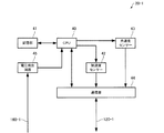
図1は、1つの好適な実施形態のセンサーシステム10のブロック図である。図1に示すように、本実施形態のセンサーシステム10は、N個のセンサーモジュール20−1〜20−N、コントロールユニット30、接続部50、電圧発生部60を含んで構成されている。
1. Sensor System Configuration FIG. 1 is a block diagram of one preferred
コントロールユニット30は、CPU32、通信部34、基準電圧発生部36を含んでいる。また、接続部50はセンサーモジュール20−1〜20−Nのうち最大でM個を接続するためのポート52−1〜52−Mを含んでいる。なお、M、N、および後述するJは自然数であり、以下の説明において特に断らない限りJ≦M≦Nの関係があるものとする。
The
図1において、センサーモジュール20−1〜20−Nの括弧内の数字はそれぞれに固有のIDであるとする。また、ポート52−1〜52−Mの括弧内の数字はそれぞれに割り当てられた固有のアドレスであるとする。なお、これらのIDやアドレスは、このような連続した数字に限るわけではなく、重複がなければ不連続な数字、文字又はこれらの組み合わせであってもよい。例えば、センサーモジュール20−1〜20−Nに固有のIDとしては、センサーモジュール20−1〜20−Nのそれぞれの製造シリアル番号等を用いてもよい。 In FIG. 1, the numbers in parentheses of the sensor modules 20-1 to 20-N are assumed to be unique IDs. The numbers in parentheses of the ports 52-1 to 52-M are assumed to be unique addresses assigned to the respective ports. These IDs and addresses are not limited to such consecutive numbers, and may be discontinuous numbers, characters, or a combination thereof as long as there is no overlap. For example, as the IDs unique to the sensor modules 20-1 to 20-N, manufacturing serial numbers of the sensor modules 20-1 to 20-N may be used.
N個のセンサーモジュール20−1〜20−Nは、その全て又は一部が同種のセンサーモジュールであるとする。本実施形態では、全てが同種のセンサーであり、その構成については後述する。 It is assumed that all or a part of the N sensor modules 20-1 to 20-N are the same type of sensor modules. In this embodiment, all are the same type of sensors, and the configuration will be described later.
そして、ポート52−1〜52−Mとセンサーモジュール20−1〜20−Nとの接続は固定的ではない。例えば図1において、IDが1であるセンサーモジュール20−1は、アドレスが2であるポート52−2に接続されている。このセンサーモジュール20−1は、ポート52−1に接続されてもよいし、ポート52−Mに接続されてもよい。 The connection between the ports 52-1 to 52-M and the sensor modules 20-1 to 20-N is not fixed. For example, in FIG. 1, the sensor module 20-1 whose ID is 1 is connected to the port 52-2 whose address is 2. The sensor module 20-1 may be connected to the port 52-1, or may be connected to the port 52-M.
コントロールユニット30は、そのCPU32が制御する通信部34を含み、ポート52−1〜52−Mを経由して接続されたセンサーモジュール20−1〜20−Nと通信する。ここでの通信は有線による通信であり、例えばUARTやI2Cといった方式であってもよい。
The
センサーモジュール20−1〜20−Nに入出力される信号120−1〜120−Nは、ポート52−1〜52−Mを経由して通信部34に入出力される。ここで、通信部34と通信を行うのは、N個のセンサーモジュール20−1〜20−Nのうち、ポート52−1〜52−Mに接続されたものだけである。 Signals 120-1 to 120-N input / output to / from the sensor modules 20-1 to 20-N are input / output to / from the communication unit 34 via the ports 52-1 to 52-M. Here, only the sensor modules 20-1 to 20-N connected to the ports 52-1 to 52-M communicate with the communication unit 34.
詳細については後述するが、コントロールユニット30はポートのアドレスを指定した送信指示をセンサーモジュール20−1〜20−Nに対して行い、その応答に含まれるIDから接続されているセンサーモジュールを特定することができる。そのため、ポート52−1〜52−Mとセンサーモジュール20−1〜20−Nとの接続は固定的ではないが、コントロールユニット30はどのセンサーモジュールが接続されているかを把握できる。
As will be described in detail later, the
コントロールユニット30は、例えば接続されたセンサーモジュールが検出した所定の物理量を受け取る。このとき、そのセンサーモジュールのIDを把握しているので、例えばセンサーモジュールの個体差によるばらつき等も適切に補正することが可能である。なお、コントロールユニット30は、得られた補正後のデータを通信部34又は別の通信手段(図外)によって、センサーシステム10の外部の機器に送信してもよい。
The
ここで、ポート52−1〜52−Mに接続されるセンサーモジュールは、ポートのアドレスを把握していなければ、コントロールユニット30からのポートのアドレスを指定した送信指示に応答できない。
Here, the sensor module connected to the ports 52-1 to 52-M cannot respond to a transmission instruction specifying the port address from the
本実施形態では、電圧発生部60が、ポートのアドレス1、2、…、Mに対応した、互いに異なる電圧V1、V2、…、VMをつくっている。本実施形態の電圧発生部60は、CPU32が制御する基準電圧発生部36が生成した基準電圧を、図1のように抵抗分割することでこれらの電圧をつくっている。そのため、単純な回路で実現可能であり、回路規模が増大することもない。
In the present embodiment, the
これらの電圧V1、V2、…、VMは、図1の信号160−1〜160−Mとして、対応するアドレスのポートに接続されたセンサーモジュールに供給される。例えば、ポート52−1〜52−Mが、複数の電気的接続を行うピンを備える構造であって、その1つのピンにポートのアドレスに対応する電圧が割り当てられていてもよい。なお、接続部50の中に電圧発生部60が含まれていてもよい。
These voltages V 1, V 2, ..., V M as a signal 160 - 1 to 160-M in FIG. 1, is supplied to the sensor module connected to the port of the corresponding address. For example, the ports 52-1 to 52-M may have a structure including a plurality of pins for electrical connection, and a voltage corresponding to the address of the port may be assigned to one of the pins. Note that the
本実施形態では、CPU32は通信部34を用いて、基準電圧発生部36からの基準電圧と、ポート52−1〜52−Mの数(図1ではM)を接続されているセンサーモジュールに伝える。詳細については後述するが、センサーモジュールは簡単な計算によって、ポートのアドレスを判断することが可能になる。
In the present embodiment, the
2.センサーモジュールの構成
図2は、本実施形態のセンサーモジュール20−1のブロック図である。ここでは、センサーモジュール20−1について例示するが、本実施形態では、センサーモジュール20−2〜20−Nについても同じ構成であるとする。なお、図1と同じ要素には同じ符号を付しており説明を省略する。
2. Configuration of Sensor Module FIG. 2 is a block diagram of the sensor module 20-1 of the present embodiment. Here, the sensor module 20-1 is illustrated, but in the present embodiment, the sensor modules 20-2 to 20-N have the same configuration. The same elements as those in FIG. 1 are denoted by the same reference numerals, and description thereof is omitted.
センサーモジュール20−1は、CPU40、記憶部41、加速度センサー42、角速度センサー43、通信部44、電圧検出回路45を含む。まず、センサーモジュール20−1がいずれかのポートに接続された場合について説明する。
The sensor module 20-1 includes a
ポートのアドレスに対応したアナログ電圧である信号160−1が電圧検出回路45に入力される。このとき、電圧検出回路45は例えばADコンバーターを含み、CPU40が後述する電圧判定処理を実行できるようにデジタル信号に変換して出力してもよい。電圧判定処理は、受け取った電圧から接続されたポートのアドレスを判断する処理である。なお、電圧検出回路45がCPU40から必要なデータを受け取り(図外)、電圧検出回路45の内部で電圧判定処理を実行し、接続されたポートのアドレスだけをCPU40に出力してもよい。このとき、CPU40の処理負担が軽減される。
A signal 160-1, which is an analog voltage corresponding to the port address, is input to the
CPU40は、電圧判定処理の結果として得られた、又は電圧検出回路45から受け取ったアドレスを記憶部41に記憶する。記憶部41は、アドレスを記憶するRAMを少なくとも含んでいる。なお、記憶部41は、RAMの他にROM、フラッシュメモリー等を含んでいてもよい。これらの不揮発性のメモリーには、例えばCPUのプログラムやセンサーモジュール20−1の固有のIDが記憶されている。
The
次に、CPU40が、コントロールユニット(図1参照)からのコマンド(指示)を信号120−1として受け取った場合について説明する。このとき、CPU40は、信号120−1に含まれるアドレスを記憶部41に記憶されたアドレスと比較する。そして、アドレスが一致した場合にはコマンドの内容に応じた動作を行う。例えば、加速度や角速度の測定開始の指示であれば、加速度センサー42、角速度センサー43に測定させる。また、コマンドが送信指示であれば、通信部44に対して、加速度センサー42、角速度センサー43の測定結果とセンサーモジュール20−1の固有のIDとを送信させる。
Next, a case where the
このとき、センサーモジュール20−1は、他のどのセンサーモジュールがどの位置に接続されているかを知る必要はない。例えば、特定のポートに特定のセンサーモジュールを繋ぐ、接続が固定化された手法(以下、従来例)がある。この従来例と比べると、センサーモジュールはポートのアドレスに対応した電圧を受け取る1つの入力端子と、電圧検出回路45が追加されるだけである。しかし、接続を固定化する必要がなくなり、人為的エラーによる誤接続の問題を解決できる。
At this time, the sensor module 20-1 does not need to know which other sensor module is connected to which position. For example, there is a method in which a specific sensor module is connected to a specific port and the connection is fixed (hereinafter, a conventional example). Compared to this conventional example, the sensor module only has one input terminal for receiving a voltage corresponding to the address of the port and a
なお、本実施形態のセンサーモジュール20−1は、直交する3軸のそれぞれに設けられた3つの加速度センサー42と3つの角速度センサー43を含むIMU(Inertial Measurement Unit:慣性姿勢計測装置)であってもよい。そして、含まれるセンサーの数や種類はこれに限らず、例えば磁気センサー、温度センサー、気圧センサー等を更に含んでいてもよい。
The sensor module 20-1 of the present embodiment is an IMU (Inertial Measurement Unit) including three
3.センサーモジュールの接続
ここで、本実施形態ではセンサーモジュールとポートの接続は固定的でないと述べたが、いくつかの接続の例を、従来例と比較して説明する。
3. Connection of Sensor Module Here, in the present embodiment, the connection between the sensor module and the port is not fixed, but some examples of connection will be described in comparison with the conventional example.
ポートに接続されたセンサーモジュールを個別に特定できるシステムの従来の手法として、前記の従来例がある。すなわち、特定のポートに特定のセンサーモジュールを繋ぐように定めた、接続を固定化した手法である。従来例では、図3(A)のように、ポートのアドレスとセンサーモジュールのIDとを1対1に対応させる。このような接続の固定化により、コントロールユニット(図1参照)は、どのセンサーモジュールがどのポートに接続されているかを把握することが可能である。 As a conventional method of a system that can individually identify sensor modules connected to ports, there is the above-described conventional example. In other words, this is a technique in which the connection is fixed so that a specific sensor module is connected to a specific port. In the conventional example, as shown in FIG. 3A, the address of the port and the ID of the sensor module are made to correspond one-to-one. By fixing such connections, the control unit (see FIG. 1) can grasp which sensor module is connected to which port.
このとき、図3(B)のようなコマンドを用いて、コントロールユニットはセンサーモジュールが検出したデータの送信を要求する。このコマンドは、検出したデータの送信を命令するコードと、センサーモジュールを指定するIDとで構成されている。なお、接続の固定化がされているので、センサーモジュールを指定するIDに代えてポートのアドレスを用いてもよい。 At this time, the control unit requests transmission of data detected by the sensor module using a command as shown in FIG. This command includes a code for instructing transmission of detected data and an ID for designating a sensor module. Since the connection is fixed, the port address may be used instead of the ID for designating the sensor module.
しかし、従来例では、人為的エラーによる誤接続があった場合に、コントロールユニットは誤りに気付くことなく処理を進める。誤接続とは、例えば図3(A)の例では、アドレス1のポートにIDが3のセンサーモジュールを接続することである。そのため、例えば補正が適切に行われず、正しいデータを得ることができない問題が生じる。
However, in the conventional example, when there is an erroneous connection due to a human error, the control unit proceeds with the process without noticing the error. For example, in the example of FIG. 3A, the erroneous connection means that a sensor module having an ID of 3 is connected to the port of
これに対し、図4(A)は、本実施形態のセンサーシステムにおけるセンサーモジュールの接続の例である。従来例と同じように接続することも可能であるが(ケース1)、ケース2のようにポートのアドレスとセンサーモジュールのIDとを無関係に接続することができる。例えばIDがMであるセンサーモジュールは、ポートに接続されたときに受け取った電圧から当該ポートのアドレス(1)を判断する。
On the other hand, FIG. 4A is an example of connection of sensor modules in the sensor system of the present embodiment. Although it is possible to connect in the same manner as in the conventional example (case 1), as in
そして、コントロールユニット(図1参照)は、図4(B)のようなコマンドを用いて、センサーモジュールが検出したデータの送信を要求する。このコマンドは、従来例(図3(B))と異なり、ポートのアドレスを用いる。コマンドで指定されたアドレスが1のとき、IDがMであるセンサーモジュールは、検出したデータとIDであるMとを送信する。この応答によって、コントロールユニットは、アドレスが1であるポートには、IDがMであるセンサーモジュールが接続されていることを把握し、例えばこのセンサーモジュールに適した補正を実行する。
And a control unit (refer FIG. 1) requests | requires transmission of the data which the sensor module detected using the command like FIG. 4 (B). Unlike the conventional example (FIG. 3B), this command uses a port address. When the address specified by the command is 1, the sensor module whose ID is M transmits detected data and M which is ID. Based on this response, the control unit recognizes that the sensor module with ID M is connected to the port with
また、図4(A)のケース2では、アドレスが2であるポートにどのセンサーモジュールも接続されていない。このとき、コントロールユニットは、例えばポートのアドレスを順に変更しながら図4(B)のコマンドを実行することで、容易に未接続を確認できる。つまり、センサーモジュールからの応答が無い場合に未接続と判断できる。このとき、次以降のアドレス(図4(A)の例ではアドレス3以降)で応答があるならば接続ミスと判断し、次以降のアドレスの全てで応答が無いならば、使用者が部分的な接続を意図的に行っていると判断してもよい。
In
ケース3は、M<Nであるとした場合の1つの接続例である。例えば、IDが2であるセンサーモジュールをアドレスが1であるポートに接続していたが、故障が生じたため、同種のセンサーモジュールであってIDがNのものを接続した場合に対応する。この場合でも、本実施形態のセンサーシステムは問題なく動作する。また、コントロールユニットは、どのセンサーモジュールがどのポートに接続されているかを把握することが可能である。
なお、センサーモジュールのIDは、検出したデータと共にでなくても送信され得る。例えば、図4(B)のコマンドで、検出したデータの送信を命令するコードに代えて、IDのみを送信させるコードを有するコマンド(以下、ID送信コマンド)があってもよい。そして、ID送信コマンドに応答して、センサーモジュールはIDのみを送信してもよい。 Note that the ID of the sensor module can be transmitted without the detected data. For example, in the command shown in FIG. 4B, there may be a command (hereinafter referred to as an ID transmission command) having a code for transmitting only an ID instead of a code for commanding transmission of detected data. In response to the ID transmission command, the sensor module may transmit only the ID.
4.電圧発生部の構成
図5は、本実施形態の電圧発生部60の1つの構成例を説明する図である。なお、図1と同じ要素には同じ符号を付しており説明を省略する。図5は、図1における電圧発生部60のR1、R2、…、RMを全て同じ抵抗値R0とした場合を示す。このとき、電圧発生部60が抵抗分割することでつくる、ポートのアドレスに対応する互いに異なる電圧を、簡単な計算で求めることが可能になる。
4). Configuration of Voltage Generating Unit FIG. 5 is a diagram illustrating one configuration example of the
図5のように、基準電圧発生部36(図1参照)が生成した基準電圧V1を、抵抗値R0のM個の抵抗素子で分割する。すると、J≦Mとして、ポートのアドレスJに対応する電圧は(M+1−J)×V1/Mで表される。なお、以下では、この式を電圧計算式という。
As shown in FIG. 5, a reference
そのため、センサーモジュールは、コントロールユニットから基準電圧V1とポートの数Mを事前情報として得られれば、電圧発生部60から受け取った電圧に基づいて、電圧計算式からアドレスJを求めることができる。
Therefore, the sensor module, as long yield the number M of the reference voltage V 1 and port from the control unit as a priori information, based on the voltage received from the
ここで、図5の電圧発生部60は1つのラダー抵抗回路から成る。しかし、図6のようにポートが左右に物理的に離れている場合に、ポートに合わせて複数の(ここでは2つの)ラダー抵抗回路で構成される方が好ましい場合がある。以下では、単位抵抗値R0の整数倍の抵抗を用いて、複数のラダー抵抗回路で構成される電圧発生部60についても、前記の電圧計算式を用いることが可能な例を示す。
Here, the
図6は、人の腕の動きを検出するために、左右の肩、ひじ、手首に対応してポート52−1〜52−6が設けられており、それぞれのポートにセンサーモジュールを接続して用いるセンサーシステムである。このセンサーシステムは衣服に組み込まれている。このとき、コントロールユニット30は中央部分に配置されることが好ましく、右手用のポート52−1〜52−3から成る通信系と、左手用のポート52−4〜52−6から成る通信系とが物理的に2つに分離している。
In FIG. 6, in order to detect the movement of a person's arm, ports 52-1 to 52-6 are provided corresponding to the left and right shoulders, elbows, and wrists, and a sensor module is connected to each port. The sensor system used. This sensor system is built into the garment. At this time, the
ここで、図5の構成の電圧発生部60を使用した場合、右手の手首まで配線を伸ばした後に、中央部まで折り返してから左手の手首まで配線を伸ばすことになる。つまり、配線の長い引き回しが生じて、適切に腕の動きを検出できない可能性がある。このような場合には、図7の構成の電圧発生部60を用いてもよい。
Here, when the
図7の電圧発生部60は、2つのラダー抵抗回路60A、60Bを含み、それぞれ右手用のポート(アドレス1〜3)から成る通信系、左手用のポート(アドレス4〜6)から成る通信系に対応させることができる。
The
このとき、2つのラダー抵抗回路における電圧を出力するノード(信号160−1〜160−6を引き出す節)がそれぞれ互いに異なるように、図7のように単位抵抗値R0の整数倍の抵抗値を持つ抵抗素子を配置する。 At this time, the resistance value that is an integral multiple of the unit resistance value R0 as shown in FIG. A resistive element having
例えば、アドレス2を割り当てられたポートに接続されたセンサーモジュールは、(5/6)V1の電圧を受け取る。これは、電圧計算式でM=6、J=2とした結果と一致する。また、例えば、アドレス4を割り当てられたポートに接続されたセンサーモジュールは、(3/6)V1の電圧を受け取る。これは、電圧計算式でM=6、J=4とした結果と一致する。
For example, the sensor module connected to the port assigned
図7の構成の電圧発生部60は、ポートの物理的配置に合わせて複数のラダー抵抗回路を含むことで、図5の場合と同じ電圧計算式を使用しながら、配線の長い引き回しを回避することを可能にする。 7 includes a plurality of ladder resistor circuits according to the physical arrangement of the ports, thereby avoiding long wiring routing while using the same voltage calculation formula as in FIG. Make it possible.
5.フローチャート
図8は、本実施形態のセンサーシステムのセンサーモジュールの制御を示すフローチャートである。具体的には、図2のCPU40が例えば記憶部41に記憶されたプログラムに従って行う制御である。
5. Flowchart FIG. 8 is a flowchart showing control of the sensor module of the sensor system of the present embodiment. Specifically, the control is performed by the
センサーモジュールは、ポートに接続されると、ポートのアドレスに対応する電圧を受け取って、電圧判定処理を行う(S10)。電圧判定処理は、受け取った電圧から接続されたポートのアドレスを判断する処理である。 When connected to the port, the sensor module receives a voltage corresponding to the address of the port and performs a voltage determination process (S10). The voltage determination process is a process of determining the address of the connected port from the received voltage.
そして、アドレスを記憶部41に記憶する(S12)。その後、コントロールユニットからの計測開始の指示を待つ(S20:N)、計測とは、本実施形態では加速度や角速度を検出することである。計測開始の指示があると(S20:Y)、コマンド中に指定されたポートのアドレスが、自身が接続されたポートのアドレスと一致するかを判断する(S22)。アドレスが一致した場合には(S22:Y)、計測を開始する(S24)。なお、不一致の場合には、次の指示を待つ(S22:N)。 Then, the address is stored in the storage unit 41 (S12). After that, a measurement start instruction from the control unit is waited (S20: N), and the measurement is to detect acceleration and angular velocity in this embodiment. If there is an instruction to start measurement (S20: Y), it is determined whether the address of the port specified in the command matches the address of the port to which it is connected (S22). If the addresses match (S22: Y), measurement is started (S24). If there is a mismatch, the next instruction is waited (S22: N).
センサーモジュールは、計測を行った後、コントロールユニットからのデータ送信の指示を待つ(S30:N)。データ送信の指示があると(S30:Y)、コマンド中に指定されたポートのアドレスが、自身が接続されたポートのアドレスと一致するかを判断する(S32)。アドレスが一致した場合には(S32:Y)、計測したデータと共に自己の固有のIDを送信する(S34)。なお、不一致の場合には、次の指示を待つ(S32:N)。 After the measurement, the sensor module waits for a data transmission instruction from the control unit (S30: N). When there is an instruction to transmit data (S30: Y), it is determined whether the address of the port specified in the command matches the address of the port to which it is connected (S32). If the addresses match (S32: Y), it transmits its own unique ID along with the measured data (S34). If there is a mismatch, the next instruction is awaited (S32: N).
なお、センサーモジュールは、電圧判定処理を行う(S10)前に、コントロールユニットからブロードキャストで、すなわち特定のポートのアドレスを指定しないで、基準電圧V1とポートの数Mについて受け取ってもよい。 Incidentally, the sensor module, before performing the voltage determination process (S10), a broadcast from the control unit, i.e. without specifying the address of a particular port may receive the number M of the reference voltage V 1 and the port.
また、計測開始の指示(S20)の前に、コントロールユニットからIDのみを送信させる指示があってもよい。このとき、センサーモジュールは、アドレスが一致した場合には自己の固有のIDを送信する。このとき、コントロールユニットは、ポートとセンサーモジュールとの接続状態をチェックすることができる。 Moreover, there may be an instruction for transmitting only the ID from the control unit before the measurement start instruction (S20). At this time, if the addresses match, the sensor module transmits its own unique ID. At this time, the control unit can check the connection state between the port and the sensor module.
以上のように、本実施態様によれば、センサーモジュールの接続位置を固定化することなく、有線接続されたセンサーモジュールを個別に識別可能なセンサーシステムを提供することができる。 As described above, according to this embodiment, it is possible to provide a sensor system that can individually identify wiredly connected sensor modules without fixing the connection positions of the sensor modules.
6.その他
本発明は、実施の形態で説明した構成と実質的に同一の構成(例えば、機能、方法及び結果が同一の構成、あるいは目的及び効果が同一の構成)を含む。また、本発明は、実施の形態で説明した構成の本質的でない部分を置き換えた構成を含む。また、本発明は、実施の形態で説明した構成と同一の作用効果を奏する構成又は同一の目的を達成することができる構成を含む。また、本発明は、実施の形態で説明した構成に公知技術を付加した構成を含む。
6). Others The present invention includes configurations that are substantially the same as the configurations described in the embodiments (for example, configurations that have the same functions, methods, and results, or configurations that have the same objects and effects). In addition, the invention includes a configuration in which a non-essential part of the configuration described in the embodiment is replaced. In addition, the present invention includes a configuration that exhibits the same operational effects as the configuration described in the embodiment or a configuration that can achieve the same object. Further, the invention includes a configuration in which a known technique is added to the configuration described in the embodiment.
10 センサーシステム、20−1〜20−N センサーモジュール、30 コントロールユニット、32 CPU、34 通信部、36 基準電圧発生部、40 CPU、41 記憶部、42 加速度センサー、43 角速度センサー、44 通信部、45 電圧検出回路、50 接続部、52−1〜52−M ポート、60 電圧発生部、60A ラダー抵抗回路、60B ラダー抵抗回路、120−1〜120−N 信号、160−1〜160−M 信号 10 sensor system, 20-1 to 20-N sensor module, 30 control unit, 32 CPU, 34 communication unit, 36 reference voltage generation unit, 40 CPU, 41 storage unit, 42 acceleration sensor, 43 angular velocity sensor, 44 communication unit, 45 voltage detection circuit, 50 connection section, 52-1 to 52-M port, 60 voltage generation section, 60A ladder resistance circuit, 60B ladder resistance circuit, 120-1 to 120-N signal, 160-1 to 160-M signal
Claims (8)
前記センサーモジュールを接続し、かつ、固有のアドレスが割り当てられているポートを複数備える接続部と、
前記アドレス毎に異なる電圧を発生させ、前記センサーモジュールに前記電圧を供給する電圧発生部と、
前記接続部を介して、前記センサーモジュールと通信するコントロールユニットと、を含み、
前記センサーモジュールは、
前記電圧発生部からの前記電圧により前記ポートの前記アドレスを判断し、前記コントロールユニットからの送信命令に基づき、検出した所定の物理量および前記固有のIDを前記コントロールユニットに送信する、センサーシステム。 A plurality of sensor modules having unique IDs;
A connection unit that connects the sensor module and includes a plurality of ports to which a unique address is assigned;
A voltage generator for generating a different voltage for each address and supplying the voltage to the sensor module;
A control unit that communicates with the sensor module via the connection,
The sensor module is
A sensor system that determines the address of the port based on the voltage from the voltage generator, and transmits the detected predetermined physical quantity and the unique ID to the control unit based on a transmission command from the control unit.
前記コントロールユニットは、
前記電圧発生部に基準電圧を供給する基準電圧発生部を含み、
前記電圧発生部は、
前記基準電圧を抵抗分割することで、前記アドレスに対応する互いに異なる電圧を発生させる、センサーシステム。 The sensor system according to claim 1.
The control unit is
A reference voltage generator for supplying a reference voltage to the voltage generator;
The voltage generator is
A sensor system that generates different voltages corresponding to the address by dividing the reference voltage by resistance.
前記電圧発生部は、
抵抗素子が直列に接続されたラダー抵抗回路を複数含み、前記ラダー抵抗回路の各々は前記基準電圧発生部に接続される、センサーシステム。 The sensor system according to claim 2,
The voltage generator is
A sensor system comprising a plurality of ladder resistor circuits in which resistor elements are connected in series, each of the ladder resistor circuits being connected to the reference voltage generator.
前記センサーモジュールは、
前記所定の物理量を検出する前に、
前記基準電圧および前記ポートの数の情報を、前記コントロールユニットから前記接続部を介して受け取る、センサーシステム。 The sensor system according to any one of claims 1 to 3,
The sensor module is
Before detecting the predetermined physical quantity,
A sensor system that receives information on the reference voltage and the number of ports from the control unit via the connection.
前記センサーモジュールは、
加速度センサーおよび角速度センサーの少なくとも一方を含む、センサーシステム。 The sensor system according to any one of claims 1 to 4,
The sensor module is
A sensor system including at least one of an acceleration sensor and an angular velocity sensor.
ポートに接続された際に前記ポートから印加される電圧を検出する電圧検出回路と、
前記電圧により前記ポートのアドレスを判断し、コントロールユニットからの送信命令に基づき、検出した所定の物理量および固有のIDを前記コントロールユニットに送信する通信部と、を備える、センサーモジュール。 A sensor that detects physical quantities;
A voltage detection circuit for detecting a voltage applied from the port when connected to the port;
And a communication unit that determines an address of the port based on the voltage and transmits a detected predetermined physical quantity and unique ID to the control unit based on a transmission command from the control unit.
前記所定の物理量を検出する前に、
基準電圧および前記ポートの数の情報を前記コントロールユニットから受け取る、センサーモジュール。 The sensor module according to claim 6 , wherein
Before detecting the predetermined physical quantity,
A sensor module that receives information of a reference voltage and the number of ports from the control unit.
加速度センサーおよび角速度センサーの少なくとも一方を含む、センサーモジュール。 The sensor module according to claim 6 or 7 ,
A sensor module including at least one of an acceleration sensor and an angular velocity sensor.
Priority Applications (3)
| Application Number | Priority Date | Filing Date | Title |
|---|---|---|---|
| JP2012087126A JP5928107B2 (en) | 2012-04-06 | 2012-04-06 | Sensor system, sensor module |
| CN2013101105190A CN103365225A (en) | 2012-04-06 | 2013-04-01 | Sensor system and sensor module identification method |
| US13/855,983 US20130268231A1 (en) | 2012-04-06 | 2013-04-03 | Sensor system and sensor module identification method |
Applications Claiming Priority (1)
| Application Number | Priority Date | Filing Date | Title |
|---|---|---|---|
| JP2012087126A JP5928107B2 (en) | 2012-04-06 | 2012-04-06 | Sensor system, sensor module |
Publications (3)
| Publication Number | Publication Date |
|---|---|
| JP2013218454A JP2013218454A (en) | 2013-10-24 |
| JP2013218454A5 JP2013218454A5 (en) | 2015-04-30 |
| JP5928107B2 true JP5928107B2 (en) | 2016-06-01 |
Family
ID=49292997
Family Applications (1)
| Application Number | Title | Priority Date | Filing Date |
|---|---|---|---|
| JP2012087126A Expired - Fee Related JP5928107B2 (en) | 2012-04-06 | 2012-04-06 | Sensor system, sensor module |
Country Status (3)
| Country | Link |
|---|---|
| US (1) | US20130268231A1 (en) |
| JP (1) | JP5928107B2 (en) |
| CN (1) | CN103365225A (en) |
Families Citing this family (12)
| Publication number | Priority date | Publication date | Assignee | Title |
|---|---|---|---|---|
| US9720872B2 (en) * | 2013-10-10 | 2017-08-01 | Qorvo Us, Inc. | Auto-configuration of devices based upon configuration of serial input pins and supply |
| US9298908B1 (en) * | 2014-10-17 | 2016-03-29 | Lexmark International, Inc. | Methods and apparatus for setting the address of a module using a voltage |
| CA2938911A1 (en) * | 2014-10-17 | 2016-04-21 | Lexmark International, Inc. | Methods for setting the address of a module |
| US9213927B1 (en) * | 2014-10-17 | 2015-12-15 | Lexmark International, Inc. | Methods for setting the address of a module |
| US9213396B1 (en) * | 2014-10-17 | 2015-12-15 | Lexmark International, Inc. | Methods and apparatus for setting the address of a module using a clock |
| CN106055044B (en) * | 2016-05-30 | 2019-06-07 | 维沃移动通信有限公司 | A kind of method and terminal of compatible identification different model sensor |
| US20190163658A1 (en) * | 2017-11-24 | 2019-05-30 | Robotis Co., Ltd. | Master and slave, and identification number setting apparatus |
| US20220170874A1 (en) * | 2019-04-15 | 2022-06-02 | Essity Hygiene And Health Aktiebolag | Data Logger Unit, Sensor Unit, Absorbent Article Management System And Identification Method |
| CN111092967B (en) * | 2019-12-31 | 2022-07-15 | 重庆菲莫科技有限公司 | Equipment address conflict processing method and system |
| CN113162805B (en) * | 2021-04-23 | 2022-05-06 | 天地(常州)自动化股份有限公司 | Configuration method of data acquisition unit and sensor |
| CN114899927B (en) * | 2022-07-14 | 2022-10-14 | 广东首航智慧新能源科技有限公司 | Battery port identification method, inverter and energy storage system |
| CN116929437B (en) * | 2023-09-15 | 2023-12-08 | 深圳和润达科技有限公司 | Sensor information identification method and device applied to cell formation component system |
Family Cites Families (11)
| Publication number | Priority date | Publication date | Assignee | Title |
|---|---|---|---|---|
| JPS63231599A (en) * | 1987-03-20 | 1988-09-27 | 株式会社東芝 | Meter reader for service value |
| US5122970A (en) * | 1988-06-17 | 1992-06-16 | Hewlett-Packard Company | Improved sensor |
| US5317693A (en) * | 1991-04-04 | 1994-05-31 | Digital Equipment Corporation | Computer peripheral device network with peripheral address resetting capabilities |
| US5831546A (en) * | 1996-05-10 | 1998-11-03 | General Signal Corporation | Automatic addressing in life safety system |
| US6255973B1 (en) * | 1999-08-26 | 2001-07-03 | Analog Devices, Inc. | Address selection circuitry and method using single analog input line |
| JP2001095748A (en) * | 1999-10-01 | 2001-04-10 | Olympus Optical Co Ltd | Connection equipment identification system |
| KR20030004387A (en) * | 2001-03-06 | 2003-01-14 | 마이크로스톤 가부시키가이샤 | Body motion detector |
| US7206878B2 (en) * | 2003-01-08 | 2007-04-17 | International Business Machines Corporation | Voltage level bus protocol for transferring data |
| FR2885710B1 (en) * | 2005-05-11 | 2007-08-03 | Stmicroelectronics Maroc | ADDRESS SELECTION FOR I2C BUS |
| JP4842573B2 (en) * | 2005-07-08 | 2011-12-21 | キヤノンファインテック株式会社 | Sensor detection circuit and device provided with the detection circuit |
| US8122159B2 (en) * | 2009-01-16 | 2012-02-21 | Allegro Microsystems, Inc. | Determining addresses of electrical components arranged in a daisy chain |
-
2012
- 2012-04-06 JP JP2012087126A patent/JP5928107B2/en not_active Expired - Fee Related
-
2013
- 2013-04-01 CN CN2013101105190A patent/CN103365225A/en active Pending
- 2013-04-03 US US13/855,983 patent/US20130268231A1/en not_active Abandoned
Also Published As
| Publication number | Publication date |
|---|---|
| CN103365225A (en) | 2013-10-23 |
| US20130268231A1 (en) | 2013-10-10 |
| JP2013218454A (en) | 2013-10-24 |
Similar Documents
| Publication | Publication Date | Title |
|---|---|---|
| JP5928107B2 (en) | Sensor system, sensor module | |
| JP7251580B2 (en) | battery system | |
| EP2559135B1 (en) | Battery management system and method for transferring data within the battery management system | |
| CN103778090B (en) | Serial communication circuit and method, IC apparatus, physical quantity measuring apparatus | |
| JP4957813B2 (en) | Communication slave and communication network system | |
| TWI235910B (en) | Apparatus for testing I/O ports of a computer motherboard | |
| JP6205756B2 (en) | Synchronous measurement system | |
| US10759470B2 (en) | Sensor device and electric power steering apparatus using same | |
| US9921628B2 (en) | Power converter for a computer device and method for operating a power converter | |
| JP2013218454A5 (en) | Sensor system, sensor module identification method, sensor module | |
| JP2021532505A (en) | Hazard Warning Device Network Testing | |
| JP2013192012A (en) | Network system, and method for setting identification information in network system | |
| CN103918223B (en) | Network system, node apparatus group, computer installation and sensing data receiving/transmission method | |
| US9785227B2 (en) | Portable electronic systems | |
| US20190361832A1 (en) | Bus system and detection method thereof | |
| JP5594116B2 (en) | I / O duplex device | |
| US20140163907A1 (en) | Systems and methods for fault detection | |
| JP7083454B2 (en) | Sensor system | |
| JP2019215964A (en) | Battery system | |
| JP6359915B2 (en) | Semiconductor device, battery monitoring system, and semiconductor device address setting method | |
| US9964971B2 (en) | Power supply device, power supply system, and power supply control method | |
| KR102597358B1 (en) | Apparatus and method for testing analog signal of industrial inverter | |
| JP2017174088A (en) | Instrument configuration management device, control management system and connection instrument identification method | |
| WO2023095411A1 (en) | Battery monitoring system, battery monitoring device, and battery monitoring method | |
| KR20230065852A (en) | Method and devices for obtaining sensor data |
Legal Events
| Date | Code | Title | Description |
|---|---|---|---|
| RD04 | Notification of resignation of power of attorney |
Free format text: JAPANESE INTERMEDIATE CODE: A7424 Effective date: 20150107 |
|
| A521 | Request for written amendment filed |
Free format text: JAPANESE INTERMEDIATE CODE: A523 Effective date: 20150316 |
|
| A621 | Written request for application examination |
Free format text: JAPANESE INTERMEDIATE CODE: A621 Effective date: 20150316 |
|
| A977 | Report on retrieval |
Free format text: JAPANESE INTERMEDIATE CODE: A971007 Effective date: 20151228 |
|
| A131 | Notification of reasons for refusal |
Free format text: JAPANESE INTERMEDIATE CODE: A131 Effective date: 20160112 |
|
| A521 | Request for written amendment filed |
Free format text: JAPANESE INTERMEDIATE CODE: A523 Effective date: 20160307 |
|
| TRDD | Decision of grant or rejection written | ||
| A01 | Written decision to grant a patent or to grant a registration (utility model) |
Free format text: JAPANESE INTERMEDIATE CODE: A01 Effective date: 20160329 |
|
| A61 | First payment of annual fees (during grant procedure) |
Free format text: JAPANESE INTERMEDIATE CODE: A61 Effective date: 20160411 |
|
| R150 | Certificate of patent or registration of utility model |
Ref document number: 5928107 Country of ref document: JP Free format text: JAPANESE INTERMEDIATE CODE: R150 |
|
| LAPS | Cancellation because of no payment of annual fees |