JP5921245B2 - Imaging apparatus and control method thereof - Google Patents
Imaging apparatus and control method thereof Download PDFInfo
- Publication number
- JP5921245B2 JP5921245B2 JP2012029906A JP2012029906A JP5921245B2 JP 5921245 B2 JP5921245 B2 JP 5921245B2 JP 2012029906 A JP2012029906 A JP 2012029906A JP 2012029906 A JP2012029906 A JP 2012029906A JP 5921245 B2 JP5921245 B2 JP 5921245B2
- Authority
- JP
- Japan
- Prior art keywords
- pan head
- image
- driving
- external device
- pan
- Prior art date
- Legal status (The legal status is an assumption and is not a legal conclusion. Google has not performed a legal analysis and makes no representation as to the accuracy of the status listed.)
- Expired - Fee Related
Links
Images


Description
本発明は、雲台付きの撮像装置及びその制御方法に関する。 The present invention relates to an imaging apparatus with a pan head and a control method thereof.
監視用途に使用される雲台付きの撮像装置は、警備室等の操作端末へ撮像画像を配信し、また操作端末から送信される雲台操作、画質設定等の制御コマンドに従って処理を行う。このような雲台付きの撮像装置において、雲台駆動中に撮像が行われた場合は、画像が流れて見辛いものになることが知られている。特に雲台の移動速度が速く、撮像装置の電荷蓄積時間が長い場合は、この現象が顕著となる。 An imaging device with a pan head used for monitoring uses distributes a captured image to an operation terminal such as a security room, and performs processing according to control commands such as pan head operation and image quality setting transmitted from the operation terminal. In such an imaging device with a pan head, it is known that when an image is picked up while the pan head is driven, an image flows and is difficult to see. In particular, this phenomenon becomes remarkable when the moving speed of the camera platform is high and the charge accumulation time of the imaging device is long.
特許文献1には、旋回をし続けながら静止画を取得する自動旋回型の雲台付き撮像システムに関する技術が開示されている。特許文献1によれば、電荷蓄積時間が長く設定されていても流れていない映像が表示装置に表示されるよう、雲台を電荷蓄積時間に応じて停止させて撮像を行い、流れている画像は表示装置に表示させないよう制御している。こうすることで常に見やすい画像が表示装置に表示される撮像システムを得ることができるようにしている。 Patent Document 1 discloses a technique related to an automatic turning type imaging system with a pan head that acquires a still image while continuing to turn. According to Japanese Patent Laid-Open No. 2004-260260, a panorama is stopped in accordance with the charge accumulation time so that an image that does not flow even if the charge accumulation time is set to be long is displayed on the display device. Is controlled not to be displayed on the display device. By doing so, it is possible to obtain an imaging system in which an easily viewable image is always displayed on the display device.
一方で、移動物体を追尾するべく雲台制御が行われている場合では、前述の参考文献に紹介されているシステムのように静止画取得のために駆動中の雲台を止めることによって、追尾物体を見失ってしまうという懸念がある。同様に、雲台駆動速度に関してユーザによる速度指定が行われている場合に、静止画取得のために雲台を停止させることは必ずしもユーザに望まれない可能性がある。 On the other hand, when pan head control is performed to track a moving object, tracking is performed by stopping the pan head that is being driven to acquire a still image, as in the system introduced in the above reference. There is concern that the object will be lost. Similarly, when the speed designation by the user regarding the pan head driving speed is performed, there is a possibility that the user does not necessarily desire to stop the pan head for acquiring a still image.
本発明は、上記の課題に鑑みてなされたものであり、雲台の駆動中の画像提供が要求された際に、提供する画像の画質と雲台の駆動速度の優先度に基づいて雲台の駆動速度の制御を適切に切り替えることが可能な撮像装置及びその制御方法を提供することを目的とする。 The present invention has been made in view of the above-described problems. When an image provision during driving of the camera platform is requested , the camera platform is based on the priority of the image quality of the image to be provided and the drive speed of the camera platform. It is an object of the present invention to provide an imaging apparatus capable of appropriately switching the control of the driving speed and its control method.
本発明の撮像装置は、制御手段と、撮像手段と、パン駆動及びチルト駆動の一方又は双方を行うことにより前記撮像手段の撮像範囲を変更する雲台と、外部機器と信号の送受信を行う通信手段とを備え、前記撮像手段により取得された画像データを、前記通信手段を介して前記外部機器に送信する画像提供を行う撮像装置であって、前記制御手段は、前記外部機器から前記画像提供の要求を受け付けた際に、前記外部機器から前記雲台の駆動速度の指定を伴う雲台駆動コマンドを受け付けて前記雲台が駆動中であった場合に、前記雲台の駆動を一時停止させることなく、前記画像提供に用いる画像データを取得する一方で、前記外部機器から前記画像提供の要求を受け付けた際に、前記外部機器から前記雲台の駆動速度の指定を伴わない雲台駆動コマンドを受け付けて前記雲台が駆動中であった場合に、前記雲台の駆動を一時停止させて、前記画像提供に用いる画像データを取得する。 The imaging apparatus of the present invention includes a control unit, an imaging unit, a pan that changes the imaging range of the imaging unit by performing one or both of pan driving and tilt driving, and communication that transmits and receives signals to and from an external device. And an image providing apparatus that provides an image to be transmitted to the external device via the communication unit, and the control unit provides the image from the external device. When the camera head is being driven by receiving a camera head drive command with designation of the camera head drive speed from the external device, the head drive is temporarily stopped . it not, while acquiring the image data used for the image provided a from an external device upon receiving a request for the image providing, the pan head from an external device without specifying the driving speed of the pan head If the camera platform accepts the dynamic command was being driven, it has suspended the driving of the pan head, to acquire image data used for the image provided.
本発明の撮像装置の制御方法は、撮像手段と、制御手段と、パン駆動及びチルト駆動の一方又は双方を行うことにより前記撮像手段の撮像範囲を変更する雲台とを備え、前記撮像手段により取得された画像データを外部機器に送信する画像提供を行う撮像装置の制御方法であって、前記制御手段は、前記外部機器から前記画像提供の要求を受け付けた際に、前記外部機器から前記雲台の駆動速度の指定を伴う雲台駆動コマンドを受け付けて前記雲台が駆動中であった場合に、前記雲台の駆動を一時停止させることなく、前記画像提供に用いる画像データを取得する一方で、前記外部機器から前記画像提供の要求を受け付けた際に、前記外部機器から前記雲台の駆動速度の指定を伴わない雲台駆動コマンドを受け付けて前記雲台が駆動中であった場合に、前記雲台の駆動を一時停止させて、前記画像提供に用いる画像データを取得する。 An imaging apparatus control method according to the present invention includes an imaging unit, a control unit, and a camera platform that changes an imaging range of the imaging unit by performing one or both of pan driving and tilt driving. An image pickup apparatus control method for providing an image for transmitting acquired image data to an external device, wherein the control means receives the image provision request from the external device and receives the cloud from the external device. If the camera platform ready for the camera platform driving command with the specified base driving speed was being driven before without temporarily stopping the driving of the Kikumodai acquires image data to be used for the image provided On the other hand, when the image provision request is received from the external device, the pan head is being driven by receiving a pan head drive command without specifying the pan head driving speed from the external device. Case, have suspended the driving of the pan head, to acquire image data used for the image provided.
本発明のプログラムは、雲台のパン駆動及びチルト駆動の一方又は双方を行うことにより撮像手段の撮像範囲を変更する駆動手順と、前記撮像手段により取得された画像データを、外部機器に送信する画像提供を行う画像提供手順と、前記外部機器から前記画像提供の要求を受け付けた際に、前記外部機器から前記雲台の駆動速度の指定を伴う雲台駆動コマンドを受け付けて前記雲台が駆動中であった場合に、前記雲台の駆動を一時停止させることなく、前記画像提供に用いる画像データを取得する一方で、前記外部機器から前記画像提供の要求を受け付けた際に、前記外部機器から前記雲台の駆動速度の指定を伴わない雲台駆動コマンドを受け付けて前記雲台が駆動中であった場合に、前記雲台の駆動を一時停止させて、前記画像提供に用いる画像データを取得する画像取得手順とをコンピュータに実行させるためのものである。 The program of the present invention transmits a driving procedure for changing the imaging range of the imaging unit by performing one or both of pan driving and tilting driving of the pan head and image data acquired by the imaging unit to an external device. When an image providing procedure for providing an image and a request for image provision from the external device are received, the camera platform is driven by receiving a camera head drive command accompanied by designation of the drive speed of the camera platform from the external device. The external device when the image provision request is received from the external device while acquiring the image data to be used for the image provision without temporarily stopping the driving of the pan head. When the pan head is being driven by receiving a pan head drive command without specifying the pan head drive speed, the pan head drive is temporarily stopped to provide the image. It is intended to execute the image acquisition procedure for acquiring image data to the computer that.
本発明によれば、雲台の駆動中の画像提供が要求された際に、提供する画像の画質と雲台の駆動速度の優先度に基づいて雲台の駆動速度の制御を適切に切り替える撮像装置を提供することができる。 According to the present invention, when the image provided in the driving of the pan head is requested, an imaging appropriately switching the control of the camera platform of the drive speed based on the priority of the image quality and the camera platform of the drive speed of the image to provide An apparatus can be provided.
以下、本発明の好適な諸実施形態について、図面を参照しながら詳細に説明する。 Hereinafter, preferred embodiments of the present invention will be described in detail with reference to the drawings.
(第1の実施形態)
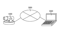
図1は、第1の実施形態による監視カメラを示す模式図である。図2は、第1の実施形態における、外部機器に画像提供を行う監視カメラを含むシステム構成を示す模式図である。
(First embodiment)
FIG. 1 is a schematic diagram showing a surveillance camera according to the first embodiment. FIG. 2 is a schematic diagram illustrating a system configuration including a monitoring camera that provides an image to an external device according to the first embodiment.
図1において、1000は本実施形態の監視カメラであり、1101はレンズの向きをパン方向に、同じく1102はチルト方向に変更する機構であり、1103はズーム機構である。
In FIG. 1,
図2において、5000は、本実施形態における外部機器を示すクライアントの機器、例えばパーソナル・コンピュータ(PC)である。監視カメラ1000とPC5000は、IPネットワーク網3000を介して相互に通信可能な状態に接続されている。PC5000は、監視カメラ1000に対して、撮像パラメータ変更や雲台駆動、映像ストリーミング開始等の各種コマンドを送信する。監視カメラ1000は、それらのコマンドに対するレスポンスや映像ストリーミングをPC5000に送信する。
In FIG. 2,
図3は、監視カメラ1000の内部構成を示すブロック図である。
図3において、1001は制御部(制御手段)であり、監視カメラ1000の全体の制御を行う。制御部1001は、例えばCPUで構成される。1002はメモリである。メモリ1002は、主に制御部1001が実行するプログラム格納領域、プログラム実行中のワーク領域、後述する撮像処理部1003が生成する画像データの格納領域等、様々なデータの格納領域として使用される。
FIG. 3 is a block diagram showing the internal configuration of the
In FIG. 3,
メモリ1002には、内部データとして雲台駆動中フラグ、動作モードが記憶されている。雲台駆動中フラグはON/OFFの状態を持ち、ONは雲台が現在駆動中であることを示し、OFFは雲台が停止中であることを示す。動作モードには、雲台の駆動(駆動速度)を優先する雲台優先モードと、静止画の画質を優先する画質優先モードとの2種類のモードがある。それぞれON/OFF、及びモード切り替えが可能であり、そのタイミングについては後述する。
The
1003は撮像処理部(撮像処理手段)である。撮像処理部1003は、当該監視カメラ1000の撮像手段で被写体を撮影して取得した撮像信号であるアナログ信号をデジタルデータに変換する。また撮像処理部1003は、ADCT(適応離散コサイン変換)等によりデータの圧縮処理を行って撮像画像の画像データを生成し、メモリ1002に出力する。撮像処理部1003は、撮像画像をメモリ1002に出力した後、制御部1001に画像取得イベントを発行する。
1004は信号の送受信を行う通信部(通信手段)である。通信部1004は、図4(a)の雲台駆動コマンド、図4(c)の静止画取得コマンドを外部機器から受信する場合に用いられる。また通信部1004は、各コマンドに対するレスポンス(図4(b)の雲台駆動レスポンス、図4(d)の静止画取得レスポンス)及び図4(e)の雲台駆動終了イベントを外部機器へ送信する場合に用いられる。通信部1004は、図4(a),(c)の各コマンドを受信した場合には、制御部1001に対して、それぞれ雲台駆動コマンド受信イベント、及び静止画取得コマンド受信イベントを発行する。
1005は撮像処理部制御部である。撮像処理部制御部1005は、制御部1001から入力される雲台を移動させる先のパン、チルトの各座標、及び移動速度に基づき、チルト機構1101及びパン機構1102の一方又は双方を制御するために使用される。
以上、図3を参照して監視カメラ1000の内部構成について説明したが、図3に示す各処理ブロックは、本発明における監視カメラの好適な実施形態の一例を説明したものでありこの限りではない。音声入力部を備えるなど、本発明の要旨の範囲内で、種々の変形及び変更が可能である。
As described above, the internal configuration of the
図4は、監視カメラ1000が外部機器に提供する制御コマンド群を示す図である。
図4(a)は雲台駆動コマンドである。この雲台駆動コマンドにより、外部機器は監視カメラ1000のパン機構1101、及びチルト機構1102を駆動(パン駆動及びチルト駆動)させることができる。即ち、監視カメラ1000より外部機器に配信される画像データの撮像範囲を変更することができる。雲台駆動コマンドの引数は、パン座標、チルト座標、パン速度、及びチルト速度である。監視カメラ1000のパン機構1101及びチルト機構1102が駆動可能な水平方向及び垂直方向の全範囲を、それぞれ−1.0から+1.0に正規化しパン座標及びチルト座標としている。パン速度及びチルト速度は、パン機構1101及びチルト機構1102の駆動可能な速度の全範囲をそれぞれ0から+1.0に正規化して速度指定値としている。雲台駆動コマンドにおけるパン速度、チルト速度はいずれも省略可能であり、省略された場合のパン速度、チルト速度は監視カメラ1000が選択する。雲台駆動コマンドを用いて外部機器は、監視カメラ1000のパン機構及びチルト機構を駆動させ、撮像範囲を任意に変更することができる。
FIG. 4 is a diagram illustrating a control command group provided to the external device by the
FIG. 4A shows a pan head drive command. With this pan head drive command, the external device can drive the
図4(b)は雲台駆動レスポンスである。監視カメラ1000は、図4(a)雲台駆動コマンドを正常に受信した場合、雲台の制御を行う前に本レスポンスを外部機器に返送する。
図4(c)は静止画取得コマンドである。この静止画取得コマンドにより、外部機器は監視カメラ1000が撮像した静止画像を取得することができる。
図4(d)は静止画取得レスポンスである。監視カメラ1000は、図4(c)静止画取得コマンドを正常に受信した場合、静止画取得レスポンスと共に撮像した静止画像データを外部機器に返送する。
図4(e)は雲台駆動終了イベントである。監視カメラ1000は、図4(a)雲台駆動コマンドに従い雲台の操作を行った後、雲台駆動終了イベントをクライアントに送信し、雲台駆動の終了を通知する。
FIG. 4B shows a pan head drive response. When the
FIG. 4C shows a still image acquisition command. With this still image acquisition command, the external device can acquire a still image captured by the
FIG. 4D shows a still image acquisition response. When the
FIG. 4E shows a pan head drive end event. After operating the camera platform in accordance with the camera platform drive command shown in FIG. 4A, the
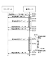
以下、図5を参照して、監視カメラ1000とこれを操作するクライアントのPC5000との間における静止画取得コマンド及び雲台駆動コマンドに関する基本的なシーケンス、及び監視カメラ1000の振る舞いを説明する。
Hereinafter, a basic sequence regarding a still image acquisition command and a pan head drive command between the
ステップS501cにおいて、監視カメラ1000は、クライアント5000から静止画取得コマンド(図4(c))を受信する。これに従って、監視カメラ1000は、S501aにおいて静止画像取得処理を行い、ステップS501rにおいてクライアント5000に対して静止画取得レスポンス(図4(d))を送信する。
In step S501c, the
ステップS502cにおいて、監視カメラ1000は、クライアント5000から雲台駆動コマンド(図4(a))を受信する。これに続いて、監視カメラ1000は、ステップS502rにおいてクライアント5000に対して雲台駆動レスポンス(図4(b))を送信し、雲台駆動処理(S502a)を開始する。ステップS502eにおいて雲台の駆動処理が終了すると、監視カメラ1000は、クライアント5000に対する雲台駆動終了イベント(図4(c))を送信する。
In step S502c, the
ステップS503cにおいて、監視カメラ1000は、クライアント5000から雲台駆動コマンド(速度指定なし:図4(a))を受信する。ステップS503rにおいて、監視カメラ1000は、クライアント5000に対して雲台駆動レスポンス(図4(b))を送信し、雲台駆動処理(S503a)を開始する。ステップS504cにおいて、雲台駆動処理が終了する前に静止画取得コマンド(図4(c))を受信した場合、監視カメラ1000は、雲台駆動を一時停止し、静止画取得処理を行う(S504a)。ステップS504rにおいて、監視カメラ1000は、クライアント5000に対して静止画取得レスポンス(図4(d))を送信すると同時に、ステップS504cで一時停止させていた雲台駆動を再開する。ステップS503eにおいて雲台の駆動処理が終了すると、監視カメラ1000は、クライアント5000に対して雲台駆動終了イベント(図4(e))を送信する。
In step S503c, the
ステップS505cにおいて、監視カメラ1000は、クライアント5000から雲台駆動コマンド(速度指定あり:図4(a))を受信する。ステップS505rにおいて、監視カメラ1000は、クライアント5000に対して雲台駆動レスポンス(図4(b))を送信し、雲台駆動処理(S505a)を開始する。ステップS506cにおいて、雲台駆動処理が終了する前に静止画取得コマンド(図4(c))を受信した場合、監視カメラ1000は、雲台駆動を一時停止することなく、静止画取得処理を行う(S506a)。ステップS506rにおいて、監視カメラ1000は、クライアント5000に対して静止画取得レスポンス(図4(d))を送信する。ステップS505eにおいて雲台の駆動処理が終了すると、監視カメラ1000は、クライアント5000に対する雲台駆動終了イベント(図4(e))を送信する。
In step S505c, the
以下、図6〜図8を参照して、監視カメラ1000の内部処理を説明する。
図6は、監視カメラ1000のメイン処理を示すフロー図である。
ステップS1100において、制御部1001はイベント待ちを行う。
ステップS1100において、静止画取得コマンド受信イベントが発生した場合、制御部1001は後述の静止画取得コマンド処理を行い(S1101)、再びステップS1100に処理を移す。
Hereinafter, the internal processing of the
FIG. 6 is a flowchart showing main processing of the
In step S1100, the
If a still image acquisition command reception event occurs in step S1100, the
ステップS1100において、雲台駆動コマンド受信イベントが発生した場合、制御部1001は後述の雲台駆動コマンド処理を行い(S1110)、再びステップS1100に処理を移す。
ステップS1100において、雲台駆動完了イベントが発生した場合、制御部1001は後述の雲台駆動完了イベント処理を行い(S1120)、再びステップS1100に処理を移す。
In step S1100, when a pan head drive command reception event occurs, the
In step S1100, when a pan head drive completion event has occurred, the
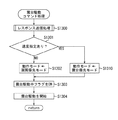
図7は、監視カメラ1000の静止画取得コマンド処理を示すフロー図である。
ステップS1200において、制御部1001は雲台駆動中フラグがONかどうかを判定し、ONの場合はステップS1210へ、OFFの場合はステップS1201へ処理を移す。
ステップS1201において、制御部1001は、静止画取得処理を実行する。
ステップS1202において、制御部1001は、レスポンス送信処理(図示しない)を実行する。ステップS1201で取得された静止画を添付した図4(d)に示す静止画取得レスポンスを、コマンド要求元のクライアントへ送信し、静止画取得コマンド処理を終了する。
FIG. 7 is a flowchart showing still image acquisition command processing of the
In step S1200, the
In step S1201, the
In step S1202, the
ステップS1210において、制御部1001は、現在の動作モードが雲台優先モードかどうかを判定する。雲台優先モードであった場合、制御部1001はステップS1201に処理を移す。雲台優先モードで無かった場合、即ち画質優先モードであった場合、制御部1001は、ステップS1211に処理を移す。
In step S1210, the
ステップS1211において、制御部1001は、撮像処理部制御部1005を使用して現在駆動中の雲台を一時停止させる。
ステップS1212において、制御部1001は、静止画取得処理を実行する。
ステップS1213において、制御部1001は、撮像処理部制御部1005を使用して現在一時停止中の雲台駆動を復帰させる。
In step S1211, the
In step S1212, the
In step S <b> 1213, the
図8は、監視カメラ1000の雲台駆動コマンド処理を示すフロー図である。
ステップS1300において、制御部1001は、レスポンス送信処理を実行する。
ステップS1301において、制御部1001は、メモリ1002を参照し現在処理中の雲台駆動コマンドに速度指定があるかどうかを参照する。具体的には、図4(a)に示す雲台駆動コマンドに含まれるパラメータのうち、パン速度及びチルド速度の指定が省略されているかどうかを判定する。速度指定がある場合、制御部1001は、動作モードを雲台優先モードに切り替える(ステップS1310)。一方速度指定がない場合、制御部1001は、動作モードを画質優先モードに切り替える(ステップS1302)。
FIG. 8 is a flowchart showing the pan / tilt head drive command processing of the
In step S1300, the
In step S1301, the
ステップS1303において、制御部1001は、雲台駆動中フラグをONにする。
ステップS1304において、制御部1001は、メモリ1002に格納されている現在処理中の雲台駆動コマンドに示されるパン座標、及びチルト座標の情報に基づき、撮像処理部制御部1005を使用して雲台駆動を開始する。
In step S1303, the
In step S1304, the
以下、監視カメラ1000の雲台駆動完了イベント処理について説明する。
先ず、制御部1001は、雲台駆動中フラグをOFFにする。
次に、制御部1001は、動作モードを画質優先モードに切り替える。
そして、制御部1001は、通信部1004を使用し図4(c)に示される雲台駆動終了イベントをコマンド要求元のクライアントへ送信する。
Hereinafter, the pan head drive completion event process of the
First, the
Next, the
Then, the
以上の処理により、雲台駆動中に静止画取得コマンドを受信した場合に、静止画の画質と雲台の駆動速度の優先順位に基づいて、雲台の駆動を適切に制御する監視カメラを提供することができる。これにより、雲台駆動中であっても状況に応じて、見やすい静止画をクライアントに提供することができ、かつ優先度の高い雲台駆動については、静止画取得コマンドの処理によってこれが妨げられることを防ぐことができる。 Through the above process, when a still image acquisition command is received during pan head driving, a surveillance camera is provided that appropriately controls pan head driving based on the priority of still image quality and pan head driving speed. can do. This makes it possible to provide easy-to-view still images to the client in accordance with the situation even when the pan head is being driven, and for the high-priority pan head drive, this is hindered by the processing of the still image acquisition command. Can be prevented.
(第2の実施形態)
第1の実施形態においては、雲台駆動コマンドの速度指定有無によって、静止画取得コマンドの動作モードを適切に切り替えることによって、状況に応じて見やすい静止画をクライアントに提供することができる監視カメラに言及し、本発明の好適な実施形態を説明した。
(Second Embodiment)
In the first embodiment, a monitoring camera that can provide an easy-to-view still image to a client according to the situation by appropriately switching the operation mode of the still image acquisition command depending on whether or not the speed of the pan head drive command is specified. Reference has been made to a preferred embodiment of the present invention.
しかしながら第1の実施形態では、動作モードの切り替えは、雲台駆動コマンドの速度指定有無によってのみ行われたがこの限りではなく、例えば特定の被写体の自動的な追尾機能による雲台駆動によって動作モードの切り替えが行われるようにしてもよい。また、第1の実施形態においては、雲台駆動中に静止画取得コマンドを受信した際、雲台優先モードであった場合は、雲台駆動状態のまま静止画取得処理を実行するようになっている。この場合、画質確保のために雲台の駆動が完了するまで静止画取得処理を延期するようにしてもよい。 However, in the first embodiment, the switching of the operation mode is performed only by the presence / absence of speed specification of the pan head drive command. However, the operation mode is not limited to this. May be switched. In the first embodiment, when the still image acquisition command is received during the pan head drive, if the pan head priority mode is selected, the still image acquisition process is executed in the pan head drive state. ing. In this case, the still image acquisition process may be postponed until the driving of the pan head is completed to ensure image quality.
以上の点を考慮した第2の実施形態を以下に説明する。なお、第1の実施形態と同じ部分については説明を省略する。 A second embodiment in consideration of the above points will be described below. Note that description of the same parts as those of the first embodiment is omitted.
図9は、監視カメラ2000の内部構成を示す模式図である。
1006は被写体追尾部である。被写体追尾部1006は、撮像処理部1003が出力する画像データを解析することで撮像範囲内に存在する物体を検出し、検出された物体を撮像範囲に収め続けられるように制御する。即ち被写体追尾部1006は、検出された物体を追尾するように撮像処理部制御部1005を用いて雲台のパン機構・チルト機構を制御する。物体の検出方法として、撮像処理部1003が生成する画像データを連続的に比較・解析するフレーム間差分法や、撮像処理部1003が生成する画像データと撮像範囲の背景画像との差分を解析する背景差分法がある。
被写体追尾部1006は、撮像範囲に物体を検出し追尾を開始した際は、追尾監視イベントを、また物体が撮像可能な範囲を逸脱する等して追尾が終了する際は、追尾終了イベントを制御部1001に発行する。
FIG. 9 is a schematic diagram showing the internal configuration of the
The
以下、図10を参照して、監視カメラ2000とこれを操作するクライアントのPC5000との間における静止画取得コマンド、雲台駆動コマンド、及び追尾機能に関する基本的なシーケンスと、監視カメラ2000の振る舞いとを説明する。
Hereinafter, with reference to FIG. 10, a basic sequence regarding a still image acquisition command, a pan head drive command, and a tracking function between the
ステップS512cにおいて、監視カメラ2000は、クライアント5000から雲台駆動コマンド(速度指定あり)を受信する。ステップS512rにおいて、監視カメラ1000は、クライアント5000に対して雲台駆動レスポンスを送信し、雲台駆動処理(S512a)を開始する。ステップS513cにおいて、雲台駆動処理S512aが終了する前に静止画取得コマンドを受信した場合、監視カメラ2000は、ここでは静止画取得処理を行わない。ステップS505eにおいて雲台の駆動処理が終了し、監視カメラ1000は、クライアント5000に対する雲台駆動終了イベントを送信する。ここで監視カメラ1000は、保留している静止画取得処理(S513a)を実行し、ステップS513rにおいて、クライアント5000に対して静止画取得レスポンスを送信する。
In step S512c, the
ステップS514sにおいて被写体追尾が開始され、被写体追尾の期間中(S514a)にステップS515cにおいて静止画取得コマンドを受信した場合、監視カメラ2000は、ここでは静止画取得処理を行わない。ステップS514eにおいて被写体追尾が終了した際に、監視カメラ2000は、保留している静止画取得処理(S515a)を実行し、ステップS515rにおいて、クライアント5000に対して静止画取得レスポンスを送信する。
If subject tracking is started in step S514s and a still image acquisition command is received in step S515c during the subject tracking period (S514a), the
図11は、監視カメラ2000のメイン処理を示すフロー図である。
ステップS1100において、制御部1001はイベント待ちを行う。
ステップS1100において、追尾開始イベントが発生した場合、制御部1001は動作モードを雲台優先モードに切り替え(S2130)、再びステップS1100に処理を移す。
FIG. 11 is a flowchart showing the main processing of the
In step S1100, the
If a tracking start event occurs in step S1100, the
ステップS1100において、追尾終了イベントが発生した場合、制御部1001は動作モードを画質優先モードに切り替え(S2140)、再びステップS1100に処理を移す。
他の処理は図6と同様であるため説明を割愛する。
In step S1100, when a tracking end event occurs, the
The other processes are the same as those in FIG.
図12は、ステップS1101にて実行される静止画取得コマンド処理を示すフロー図である。
ステップS2210において、制御部1001は、現在の動作モードが雲台優先モードかどうかを判定する。雲台優先モードであった場合、制御部1001はステップS1200に処理を移す。雲台優先モードで無かった場合、即ち画質優先モードであった場合、制御部1001は、ステップS1211に処理を移す。
他の処理は7と同様であるため説明を割愛する。
FIG. 12 is a flowchart showing still image acquisition command processing executed in step S1101.
In step S2210, the
The other processing is the same as 7 and will not be described.
以上の処理により、監視カメラ2000は、雲台優先モードにおける雲台駆動時の静止画取得コマンドの実行を、雲台駆動が完了するまで保留することによって、雲台優先モードにおいても見やすい静止画を提供することができるようになる。また、物体追尾機能の動作状況に応じて、雲台優先モードと画質優先モードの切り替えを行うことで、雲台駆動コマンドのみでなく、他の優先的な雲台駆動の機能にも適用できる。
With the above processing, the
以上、本発明による撮像装置及びその制御方法について第1及び第2の実施形態に示したが、各実施形態は必ずしも上述の限りでなく、部分的に変更されてもよい。具体的には、以下の(1)〜(3)のように、部分的に適宜変更するようにしてもよい。 As described above, the imaging apparatus and the control method thereof according to the present invention are shown in the first and second embodiments, but each embodiment is not necessarily limited to the above, and may be partially changed. Specifically, it may be appropriately changed partially as in the following (1) to (3).
(1)第2の実施形態において、画質優先モードにおける雲台駆動中の静止画取得処理(S1212)は、雲台駆動を停止(S1211)させてから行うようになっているが、必ずしも完全に雲台を停止させる必要はない。シャッタースピードや撮像地点の明るさを鑑みて、本発明の目的である流れていない見やすい静止画取得のために十分な速度まで雲台駆動速度を減速する速度制御を行って、静止画取得処理を実施するようにしてもよい。 (1) In the second embodiment, the still image acquisition process (S1212) during the pan head drive in the image quality priority mode is performed after the pan head drive is stopped (S1211). There is no need to stop the head. In view of the shutter speed and the brightness of the imaging point, the speed control is performed to reduce the pan head drive speed to a speed sufficient for easy-to-read still image acquisition that is the object of the present invention, and still image acquisition processing is performed. You may make it implement.
(2)第2の実施形態において、画質優先モードにおける雲台駆動中の静止画取得処理(S1212)の前後では、雲台駆動速度を変更(S1211)、復帰(S1213)するようにしているが、必ずしもこの限りではない。シャッタースピードの向上と復帰を含む、他のあらゆる撮像パラメータの変更、復帰を併せて実施、或いは単独で実施することによって雲台駆動中の撮像画質向上が図れるようにしてもよい。例えば、シャッタースピードの向上と復帰を含む撮像パラメータの変更を行い、画像提供に用いる画像データの取得完了後に、撮像パラメータを元に戻すことが考えられる。 (2) In the second embodiment, the pan head drive speed is changed (S1211) and returned (S1213) before and after the still image acquisition processing (S1212) during pan head drive in the image quality priority mode. However, this is not necessarily the case. It is also possible to improve the imaging image quality while driving the pan head by changing or returning all other imaging parameters including the improvement and restoration of the shutter speed, or by carrying out alone. For example, it is conceivable to change the imaging parameter including improvement and return of the shutter speed, and to return the imaging parameter to the original after completion of acquisition of the image data used for providing the image.
(3)第1及び第2の実施形態において、動作モードの切り替えは、雲台駆動コマンドの速度指定有無、及び物体追尾機能の開始・終了によってのみ行われているがこの限りではなく、あらゆる雲台駆動の優先度に応じて、動作モードが切り替わるようにしてもよい。一例として、撮像装置内部のイベントに応じてプリセットされた位置への雲台を駆動させる機能が挙げられる。本機能によって、例えば監視カメラの外部入力端子に、ドア閉開を検出するセンサが接続されており、本外部入力端子の状態変化によるイベントが発生した場合に、当該ドアが撮像範囲に入るよう雲台を駆動させるような設定が可能である。このようなイベント発生による雲台駆動の開始のタイミングで動作モードを雲台優先モードに切り替え、雲台駆動の終了で画質優先モードに切り替えるようにしてもよい。 (3) In the first and second embodiments, the switching of the operation mode is performed only by the presence / absence of speed specification of the pan head drive command and the start / end of the object tracking function. The operation mode may be switched according to the priority of the table drive. As an example, there is a function of driving a pan head to a preset position according to an event in the imaging apparatus. With this function, for example, a sensor that detects whether the door is open or closed is connected to the external input terminal of the surveillance camera. Settings that drive the table are possible. The operation mode may be switched to the pan head priority mode at the start timing of the pan head drive when such an event occurs, and may be switched to the image quality priority mode at the end of the pan head drive.
(4)第1及び第2の実施形態において、動作モードの切り替えは自動で行われるようになっているが、この限りではない。設定画面等で予め入力されたユーザの意図する動作モードが採用されるようにしてもよい。 (4) In the first and second embodiments, the operation mode is automatically switched, but this is not restrictive. The operation mode intended by the user input in advance on the setting screen or the like may be adopted.
(本発明を適用した他の実施形態)
上述した第1及び第2の実施形態による監視カメラの主要構成である制御部1001、撮像処理部1003、通信部1004、撮像処理部制御部1005の各機能、及び監視カメラの制御方法の各ステップ(例えば図6〜図8、図11及び図12の各ステップ)は、コンピュータのRAMやROM等に記憶されたプログラムが動作することによって実現できる。このプログラム及び当該プログラムを記録したコンピュータ読み取り可能な記憶媒体は本発明に含まれる。
(Other embodiments to which the present invention is applied)
Steps of the
上記のプログラムは、例えばCD−ROMのような記憶媒体に記録し、或いは各種伝送媒体を介し、コンピュータに提供される。上記のプログラムを記録する記憶媒体としては、CD−ROM以外に、フレキシブルディスク、ハードディスク、磁気テープ、光磁気ディスク、不揮発性メモリカード等を用いることができる。他方、上記のプログラムの伝送媒体としては、プログラム情報を搬送波として伝搬させて供給するためのコンピュータネットワークシステムにおける通信媒体を用いることができる。コンピュータネットワークシステムとしては、LAN、インターネットの等のWAN、無線通信ネットワーク等が、通信媒体としては、光ファイバ等の有線回線や無線回線等が挙げられる。 The above program is recorded in a storage medium such as a CD-ROM or provided to a computer via various transmission media. As a storage medium for recording the program, a flexible disk, a hard disk, a magnetic tape, a magneto-optical disk, a nonvolatile memory card, and the like can be used in addition to the CD-ROM. On the other hand, a communication medium in a computer network system for propagating and supplying program information as a carrier wave can be used as the program transmission medium. The computer network system includes a WAN such as a LAN and the Internet, a wireless communication network, and the like, and the communication medium includes a wired line such as an optical fiber, a wireless line, and the like.
また、コンピュータが供給されたプログラムを実行することにより第1及び第2の実施形態の機能が実現されるだけでなく、例えば以下の場合にも、かかるプログラムは本発明に含まれる。第1の場合として、そのプログラムがコンピュータにおいて稼働しているOS(オペレーティングシステム)或いは他のアプリケーションソフト等と共同して第1及び第2の実施形態の機能が実現される場合がある。第2の場合として、供給されたプログラムの処理の全て或いは一部がコンピュータの機能拡張ボードや機能拡張ユニットにより行われて第1及び第2の実施形態の機能が実現される場合がある。 Further, not only the functions of the first and second embodiments are realized by executing a program supplied by a computer, but such a program is also included in the present invention in the following cases, for example. As a first case, the functions of the first and second embodiments may be realized in cooperation with an OS (operating system) or other application software running on the computer. In the second case, all or part of the processing of the supplied program may be performed by a function expansion board or a function expansion unit of a computer to realize the functions of the first and second embodiments.
1000,2000 監視カメラ
1001 制御部
1002 メモリ
1003 撮像処理部
1004 通信部
1005 撮像処理部制御部
1101 パン機構
1102 チルト機構
3000 IPネットワーク網
5000 PC
1000, 2000
Claims (3)
撮像手段と、
パン駆動及びチルト駆動の一方又は双方を行うことにより前記撮像手段の撮像範囲を変更する雲台と、
外部機器と信号の送受信を行う通信手段と
を備え、
前記撮像手段により取得された画像データを、前記通信手段を介して前記外部機器に送信する画像提供を行う撮像装置であって、
前記制御手段は、前記外部機器から前記画像提供の要求を受け付けた際に、前記外部機器から前記雲台の駆動速度の指定を伴う雲台駆動コマンドを受け付けて前記雲台が駆動中であった場合に、前記雲台の駆動を一時停止させることなく、前記画像提供に用いる画像データを取得する一方で、前記外部機器から前記画像提供の要求を受け付けた際に、前記外部機器から前記雲台の駆動速度の指定を伴わない雲台駆動コマンドを受け付けて前記雲台が駆動中であった場合に、前記雲台の駆動を一時停止させて、前記画像提供に用いる画像データを取得することを特徴とする撮像装置。 Control means;
Imaging means;
A pan head for changing the imaging range of the imaging means by performing one or both of pan driving and tilt driving;
A communication means for transmitting / receiving signals to / from an external device,
An image pickup apparatus that provides an image to transmit image data acquired by the image pickup means to the external device via the communication means,
When the control means accepts the image provision request from the external device, the pan is being driven by accepting a pan head drive command with designation of the pan head driving speed from the external device. In this case, the image data used for providing the image is acquired without temporarily stopping the driving of the pan head, while the pan head is received from the external device when the image provision request is received from the external device. of when the accepting panhead driving command without specifying the drive speed camera platform was being driven, it has suspended the driving of the pan head, to acquire the image data used for the image providing An imaging device that is characterized.
前記制御手段は、前記外部機器から前記画像提供の要求を受け付けた際に、前記外部機器から前記雲台の駆動速度の指定を伴う雲台駆動コマンドを受け付けて前記雲台が駆動中であった場合に、前記雲台の駆動を一時停止させることなく、前記画像提供に用いる画像データを取得する一方で、前記外部機器から前記画像提供の要求を受け付けた際に、前記外部機器から前記雲台の駆動速度の指定を伴わない雲台駆動コマンドを受け付けて前記雲台が駆動中であった場合に、前記雲台の駆動を一時停止させて、前記画像提供に用いる画像データを取得することを特徴とする撮像装置の制御方法。 An image pickup means, a control means, and a pan head for changing the image pickup range of the image pickup means by performing one or both of pan driving and tilt driving, and transmitting image data acquired by the image pickup means to an external device An image pickup apparatus control method for providing an image to be provided,
When the control means accepts the image provision request from the external device, the pan is being driven by accepting a pan head drive command with designation of the pan head driving speed from the external device . If, without temporarily stopping the driving of the front Kikumodai, while acquiring the image data used for the image providing, when from the external device accepts the request for the image providing, the cloud from the external device If the camera platform accepts panhead driving command without specifying a base driving speed was being driven, it has suspended the driving of the pan head, to acquire image data used for the image provided A method for controlling an image pickup apparatus.
前記撮像手段により取得された画像データを、外部機器に送信する画像提供を行う画像提供手順と、
前記外部機器から前記画像提供の要求を受け付けた際に、前記外部機器から前記雲台の駆動速度の指定を伴う雲台駆動コマンドを受け付けて前記雲台が駆動中であった場合に、前記雲台の駆動を一時停止させることなく、前記画像提供に用いる画像データを取得する一方で、前記外部機器から前記画像提供の要求を受け付けた際に、前記外部機器から前記雲台の駆動速度の指定を伴わない雲台駆動コマンドを受け付けて前記雲台が駆動中であった場合に、前記雲台の駆動を一時停止させて、前記画像提供に用いる画像データを取得する画像取得手順と
をコンピュータに実行させるためのプログラム。 A driving procedure for changing the imaging range of the imaging means by performing one or both of pan driving and tilting driving of the camera platform;
An image providing procedure for providing an image for transmitting the image data acquired by the imaging means to an external device;
When the image provision request is received from the external device, the platform is being driven by receiving a pan head drive command accompanied by designation of the driving speed of the pan head from the external device. While acquiring the image data to be used for providing the image without temporarily stopping the driving of the platform, when the request for providing the image is received from the external device, the drive speed of the camera platform is specified from the external device. An image acquisition procedure for receiving a pan head drive command not accompanied by a pan head and temporarily stopping the pan head drive to obtain image data used for providing the image when the pan head is being driven.
A program that causes a computer to execute .
Priority Applications (1)
| Application Number | Priority Date | Filing Date | Title |
|---|---|---|---|
| JP2012029906A JP5921245B2 (en) | 2012-02-14 | 2012-02-14 | Imaging apparatus and control method thereof |
Applications Claiming Priority (1)
| Application Number | Priority Date | Filing Date | Title |
|---|---|---|---|
| JP2012029906A JP5921245B2 (en) | 2012-02-14 | 2012-02-14 | Imaging apparatus and control method thereof |
Publications (3)
| Publication Number | Publication Date |
|---|---|
| JP2013168745A JP2013168745A (en) | 2013-08-29 |
| JP2013168745A5 JP2013168745A5 (en) | 2015-03-05 |
| JP5921245B2 true JP5921245B2 (en) | 2016-05-24 |
Family
ID=49178851
Family Applications (1)
| Application Number | Title | Priority Date | Filing Date |
|---|---|---|---|
| JP2012029906A Expired - Fee Related JP5921245B2 (en) | 2012-02-14 | 2012-02-14 | Imaging apparatus and control method thereof |
Country Status (1)
| Country | Link |
|---|---|
| JP (1) | JP5921245B2 (en) |
Families Citing this family (3)
| Publication number | Priority date | Publication date | Assignee | Title |
|---|---|---|---|---|
| US9769369B2 (en) | 2013-11-21 | 2017-09-19 | Canon Kabushiki Kaisha | Imaging apparatus, imaging system, control method of imaging apparatus, and storage medium |
| JP6245958B2 (en) * | 2013-11-21 | 2017-12-13 | キヤノン株式会社 | IMAGING DEVICE, EXTERNAL DEVICE, IMAGING SYSTEM, IMAGING DEVICE CONTROL METHOD, EXTERNAL DEVICE CONTROL METHOD, IMAGING SYSTEM CONTROL METHOD, AND PROGRAM |
| JP7393245B2 (en) * | 2020-02-26 | 2023-12-06 | キヤノン株式会社 | Imaging device, its control method, program, storage medium |
Family Cites Families (5)
| Publication number | Priority date | Publication date | Assignee | Title |
|---|---|---|---|---|
| JP3202606B2 (en) * | 1996-07-23 | 2001-08-27 | キヤノン株式会社 | Imaging server and its method and medium |
| JP4119068B2 (en) * | 2000-03-14 | 2008-07-16 | 株式会社東芝 | Camera control system |
| JP4759322B2 (en) * | 2005-06-08 | 2011-08-31 | キヤノン株式会社 | Cradle device, imaging system control method, and computer program |
| JP2007110622A (en) * | 2005-10-17 | 2007-04-26 | Canon Inc | Imaging apparatus, control method, control program, and storage medium |
| JP4914171B2 (en) * | 2006-10-16 | 2012-04-11 | キヤノン株式会社 | Imaging device control method and camera system |
-
2012
- 2012-02-14 JP JP2012029906A patent/JP5921245B2/en not_active Expired - Fee Related
Also Published As
| Publication number | Publication date |
|---|---|
| JP2013168745A (en) | 2013-08-29 |
Similar Documents
| Publication | Publication Date | Title |
|---|---|---|
| KR102087690B1 (en) | Method and apparatus for playing video content from any location and any time | |
| KR101655056B1 (en) | Wireless video camera | |
| US9215377B2 (en) | Digital zoom with sensor mode change | |
| US20220284925A1 (en) | Real time video special effects system and method | |
| JP6081440B2 (en) | Method and apparatus for prompting based on smart glasses | |
| JP2016123137A (en) | Image communication apparatus and imaging apparatus | |
| JP6747158B2 (en) | Multi-camera system, camera, camera processing method, confirmation device, and confirmation device processing method | |
| CN104580874B (en) | camera equipment and method for realizing photographing | |
| CN103139475A (en) | Imaging device | |
| WO2017218834A1 (en) | System and method for capturing and viewing panoramic images having motion parralax depth perception without images stitching | |
| JP6326892B2 (en) | Imaging system, imaging method, image reproducing apparatus, and program | |
| JP2023519291A (en) | Method for resuming playback of multimedia content between devices | |
| JP5921245B2 (en) | Imaging apparatus and control method thereof | |
| WO2019128400A1 (en) | Method for controlling movement of photographing view angle of smart glasses | |
| JP2015139118A (en) | Imaging apparatus, imaging control method and program | |
| WO2020000394A1 (en) | Time-lapse photography control method and control device, imaging system, and storage medium | |
| US20150022680A1 (en) | Imaging apparatus, external apparatus, imaging system, method for controlling imaging apparatus, method for controlling external apparatus, method for controlling imaging system, and storage medium | |
| JP6721084B2 (en) | Zoom control device, zoom control method, and program | |
| WO2015085930A1 (en) | Method and apparatus for comprehensively controlling photography | |
| JP2002218309A (en) | Imaging apparatus and method for interval imaging of the same | |
| WO2020170604A1 (en) | Information processing device, information processing method, and program | |
| JP2015212876A (en) | Video reproduction system | |
| US20170171492A1 (en) | Display control apparatus, imaging apparatus, and display control method | |
| JP6326891B2 (en) | Image data generation system, image data generation method, image processing apparatus, and program | |
| JP7199808B2 (en) | Imaging device and its control method |
Legal Events
| Date | Code | Title | Description |
|---|---|---|---|
| A521 | Request for written amendment filed |
Free format text: JAPANESE INTERMEDIATE CODE: A523 Effective date: 20150120 |
|
| A621 | Written request for application examination |
Free format text: JAPANESE INTERMEDIATE CODE: A621 Effective date: 20150120 |
|
| A977 | Report on retrieval |
Free format text: JAPANESE INTERMEDIATE CODE: A971007 Effective date: 20151019 |
|
| A131 | Notification of reasons for refusal |
Free format text: JAPANESE INTERMEDIATE CODE: A131 Effective date: 20151110 |
|
| A521 | Request for written amendment filed |
Free format text: JAPANESE INTERMEDIATE CODE: A523 Effective date: 20160106 |
|
| TRDD | Decision of grant or rejection written | ||
| A01 | Written decision to grant a patent or to grant a registration (utility model) |
Free format text: JAPANESE INTERMEDIATE CODE: A01 Effective date: 20160315 |
|
| A61 | First payment of annual fees (during grant procedure) |
Free format text: JAPANESE INTERMEDIATE CODE: A61 Effective date: 20160412 |
|
| R151 | Written notification of patent or utility model registration |
Ref document number: 5921245 Country of ref document: JP Free format text: JAPANESE INTERMEDIATE CODE: R151 |
|
| LAPS | Cancellation because of no payment of annual fees |