JP5919590B2 - Fluid power generator - Google Patents
Fluid power generator Download PDFInfo
- Publication number
- JP5919590B2 JP5919590B2 JP2012276833A JP2012276833A JP5919590B2 JP 5919590 B2 JP5919590 B2 JP 5919590B2 JP 2012276833 A JP2012276833 A JP 2012276833A JP 2012276833 A JP2012276833 A JP 2012276833A JP 5919590 B2 JP5919590 B2 JP 5919590B2
- Authority
- JP
- Japan
- Prior art keywords
- impeller
- impeller shaft
- sprocket
- shaft
- bearing
- Prior art date
- Legal status (The legal status is an assumption and is not a legal conclusion. Google has not performed a legal analysis and makes no representation as to the accuracy of the status listed.)
- Expired - Fee Related
Links
Images


Classifications
-
- Y—GENERAL TAGGING OF NEW TECHNOLOGICAL DEVELOPMENTS; GENERAL TAGGING OF CROSS-SECTIONAL TECHNOLOGIES SPANNING OVER SEVERAL SECTIONS OF THE IPC; TECHNICAL SUBJECTS COVERED BY FORMER USPC CROSS-REFERENCE ART COLLECTIONS [XRACs] AND DIGESTS
- Y02—TECHNOLOGIES OR APPLICATIONS FOR MITIGATION OR ADAPTATION AGAINST CLIMATE CHANGE
- Y02E—REDUCTION OF GREENHOUSE GAS [GHG] EMISSIONS, RELATED TO ENERGY GENERATION, TRANSMISSION OR DISTRIBUTION
- Y02E10/00—Energy generation through renewable energy sources
- Y02E10/20—Hydro energy
Landscapes
- Hydraulic Turbines (AREA)
Description
本発明は、羽根車を用いた水力や風力などの流体力発電装置に関し、特に、巻き掛け伝動手段を介して原動側である羽根車の軸から従動側の発電機の軸へ駆動力を伝達する機構に関する。 TECHNICAL FIELD The present invention relates to a hydroelectric power generator using an impeller such as hydraulic power or wind power, and in particular, transmits a driving force from an impeller shaft on a driving side to a shaft of a driven generator via a winding transmission means. It is related with the mechanism to do.
水力発電は、これまで、ダムによる貯水等で得られる大量の水の落差を利用して発電を行う大規模のものが主流であった。しかしながら、従来、水力発電の適用対象外とされてきた、流れる水量の少ない小規模の河川や水路においても、近年、再生可能エネルギーへの注目の高まりを受け、こうした小規模の河川や水路に対応した、小型の水車を用いた水力発電装置が設置、活用されるようになっている。 Until now, hydroelectric power generation has been mainly conducted on a large scale, which generates electricity using a large drop of water obtained by dam storage. However, even in small rivers and waterways that have been excluded from the scope of hydroelectric power generation and have a small amount of flowing water in recent years, in response to growing attention to renewable energy, these small rivers and waterways have been supported. A hydroelectric power generation apparatus using a small water wheel is installed and utilized.
こうした小型の水力発電装置としては、水車、すなわち羽根車の中心に位置する羽根車軸を垂直に支持し、流れる水の中に羽根車を位置させる一方、発電機や、羽根車軸から発電機まで駆動力を伝達する機構は、保守性等を考慮して水上に配設する、立軸形の構造を採用したものが増えている。このような水力発電装置の例として、特開2007−177797号公報に開示されるものがある。 As such a small hydroelectric power generator, the impeller shaft located at the center of the impeller, that is, the impeller is vertically supported, and the impeller is positioned in the flowing water, while the generator or impeller shaft is driven from the impeller to the generator. An increasing number of mechanisms for transmitting force adopt a vertical shaft structure that is arranged on the water in consideration of maintainability and the like. An example of such a hydroelectric generator is disclosed in Japanese Patent Application Laid-Open No. 2007-177797.
従来の水力発電装置は前記特許文献に例示される構成を有しており、このような小型の水力発電装置では、装置を貫通する水路内で水流を受けて回転する羽根車を適切に支持するために、羽根車軸は、羽根車を挟むように配置された複数の軸受で両持ち支持される。この羽根車軸の軸受は、水流と接触する場合を考慮して耐水性等を配慮する必要があり、特に、羽根車が立軸形の場合、羽根車の両側にある軸受のうち、下側の軸受は常に水中にあることから、水中の異物等の影響も受けにくい構造が必要となる。水中に軸受を設ける場合、軸の円滑な回転を実現するために、構造が簡単でトラブルを生じにくく、異物にも強いすべり軸受を採用することが多い。ただし、すべり軸受では、長期の使用により軸や軸受材が摩耗し、軸受の摺動面間に過大なクリアランスが生じることがある。 A conventional hydroelectric generator has a configuration exemplified in the above-mentioned patent document, and such a small hydroelectric generator appropriately supports an impeller that rotates by receiving a water flow in a water passage that penetrates the apparatus. Therefore, the impeller shaft is supported at both ends by a plurality of bearings arranged so as to sandwich the impeller. This impeller shaft bearing needs to consider water resistance in consideration of the case where it is in contact with the water flow. Especially when the impeller is a vertical shaft type, the lower bearing among the bearings on both sides of the impeller is required. Since the water is always in the water, a structure that is not easily affected by foreign matter in the water is required. When bearings are provided in water, a slide bearing is often used that is simple in structure and less prone to troubles and is resistant to foreign matters in order to achieve smooth rotation of the shaft. However, in slide bearings, shafts and bearing materials may wear due to long-term use, resulting in excessive clearance between the sliding surfaces of the bearings.
水中側の軸受におけるこうしたクリアランスは、水流の力を受ける羽根車軸をがたつかせ、他の軸受の支持構造によっては、羽根車軸の傾きを招き、羽根車軸の水上部分にもぶれを発生させることとなる。水力発電装置の水上部分には、羽根車軸から発電機側に駆動力を伝達する機構が設けられているが、駆動力の伝達にベルトやチェーン等の巻き掛け伝動手段を用いている場合、羽根車軸のぶれは伝動手段の張り具合に影響を及す。最悪の場合、羽根車軸のぶれで伝動手段が緩んで、羽根車軸から発電機側へ適切に駆動力を伝達できなくなり、発電が適切に行えなくなるなどの問題が生じるという課題を有していた。 Such clearance in bearings on the underwater side fluctuates the impeller shaft that receives the force of the water flow, and depending on the support structure of other bearings, the impeller shaft may be inclined and the water on the impeller shaft may be shaken. Become. A mechanism for transmitting the driving force from the impeller shaft to the generator side is provided in the water portion of the hydroelectric generator, but if a winding transmission means such as a belt or a chain is used to transmit the driving force, the blade Shaking of the axle affects the tension of the transmission means. In the worst case, there is a problem that the transmission means loosens due to the shake of the impeller shaft, so that the driving force cannot be properly transmitted from the impeller shaft to the generator side, and the power generation cannot be performed properly.
本発明は前記課題を解消するためになされたもので、羽根車軸の軸受が摩耗しても、羽根車軸の変位が伝動手段を緊張させる方向に生じて、伝動手段による駆動力の適切な伝達が維持され、そのまま発電を問題なく実行できる流体力発電装置を提供することを目的とする。 The present invention has been made to solve the above problems. Even if the bearing of the impeller shaft is worn, the displacement of the impeller shaft occurs in the direction of tensioning the transmission means, and the transmission of the driving force by the transmission means is appropriately performed. An object of the present invention is to provide a hydrodynamic power generation apparatus that is maintained and can perform power generation without any problem.
本発明に係る流体力発電装置は、ケーシングを貫通して設けられた流路部を通る流体の流れの力で羽根車を回転させ、羽根車から発電機に駆動力を伝えて発電を行う流体力発電装置において、羽根車の回転中心位置で羽根車と一体に取付けられ、ケーシングにおける前記流路部を挟む両側の所定箇所でそれぞれ回転可能に支持される羽根車軸と、ケーシングの流路部外側となる部分に延長配設された前記羽根車軸の一方の端部に、直接取付けて、又は、減速機構もしくは増速機構を介在させて配設され、少なくとも前記羽根車軸と連動して回転する状態とされる、駆動プーリ又はスプロケットと、前記発電機の入力軸に、直接取付けて、又は、減速機構もしくは増速機構を介在させて配設され、少なくとも前記入力軸と連動して回転する状態とされる、従動プーリ又はスプロケットと、前記駆動プーリ又はスプロケットと前記従動プーリ又はスプロケットに巻き掛けられて配設され、前記駆動プーリ又はスプロケットから、前記従動プーリ又はスプロケットに駆動力を伝達する無端の伝動手段と、前記羽根車軸の一方の端部寄りで、且つ前記流路部の外側となるケーシングの所定位置に設けられ、前記駆動プーリ又はスプロケットと前記羽根車との間の羽根車軸所定位置を支持する第一の軸受と、当該第一の軸受とは流路部を挟んで反対側となるケーシングの流路部に面する所定部位に設けられ、前記羽根車軸の他方の端部を支持する第二の軸受とを備え、前記第二の軸受が、ケーシングに固定されるハウジング部と、当該ハウジング部と羽根車軸他端部との間に介在して、羽根車軸の他端部の回動可能状態を維持するブシュとを有し、前記第一の軸受が、前記第二の軸受における羽根車軸支持位置のラジアル方向へのずれに伴う羽根車軸の傾きを許容する構造とされ、前記羽根車軸、第一の軸受、及び第二の軸受が、前記従動プーリ又はスプロケットに対し、流体の流れ方向における上流側に位置するものである。 The hydrodynamic power generation device according to the present invention is a flow that rotates an impeller with the force of a fluid flow passing through a flow passage provided through a casing and transmits power to the generator from the impeller to generate power. In the physical power generation device, an impeller shaft that is integrally attached to the impeller at the rotation center position of the impeller and is rotatably supported at predetermined positions on both sides of the flow passage portion in the casing, and the outer flow passage portion of the casing Directly attached to one end portion of the impeller shaft that is extended in the portion to be, or disposed via a speed reduction mechanism or a speed increasing mechanism, and at least rotates in conjunction with the impeller shaft The drive pulley or sprocket that is directly attached to the generator input shaft, or arranged with a speed reduction mechanism or speed increasing mechanism interposed, and at least rotating in conjunction with the input shaft A driven pulley or sprocket, an endless transmission that is wound around the drive pulley or sprocket and the driven pulley or sprocket and transmits a driving force from the drive pulley or sprocket to the driven pulley or sprocket. And a predetermined position of the casing near one end of the impeller shaft and outside the flow path portion, and supports a predetermined position of the impeller shaft between the drive pulley or sprocket and the impeller The first bearing and the first bearing are provided at a predetermined portion facing the flow passage portion of the casing on the opposite side across the flow passage portion, and support the other end portion of the impeller shaft. And the second bearing is interposed between the housing portion fixed to the casing and the other end portion of the housing portion and the impeller shaft. A bush that maintains the pivotable state of the other end of the shaft, and the first bearing allows an inclination of the impeller shaft accompanying a radial shift of an impeller shaft support position in the second bearing. The impeller shaft, the first bearing, and the second bearing are located on the upstream side in the fluid flow direction with respect to the driven pulley or sprocket.
このように本発明によれば、羽根車軸をその中間位置で支持する第一の軸受が、羽根車軸が傾くのを許容すると共に、羽根車軸やその軸受を発電機側の従動プーリ又はスプロケットよりも流体流れ方向の上流側となる位置に配置して、羽根車が水流により押されるのに伴ってこの押された側に羽根車軸が傾いた場合、羽根車軸の一端部に配置した駆動プーリ又はスプロケットが、従動プーリ又はスプロケットから遠ざかる向きへ動くようにしている。これにより、流路部に面して流体と接触する状況で軸受として機能するブシュの構造上の特性から、摩耗が生じやすい羽根車軸他端部側の第二の軸受で、摩耗に伴う羽根車軸他端部の支持位置のずれが生じる状況となっても、羽根車軸は、羽根車が流体流により押される向きに、第二の軸受での摩耗の分、軸他端部をずらして傾いた状態で回転でき、且つ、羽根車軸の一端部における駆動プーリ又はスプロケットは、従動プーリ又はスプロケットから遠ざかる向きにずれて、伝動手段の張りを維持できることとなり、軸受での摩耗が進行しても伝動手段が緩んで駆動力を伝えにくい状態に陥ることがなく、伝動手段を介して発電機が適切に駆動され、問題なく発電を行える。 As described above, according to the present invention, the first bearing that supports the impeller shaft at its intermediate position allows the impeller shaft to be tilted, and the impeller shaft and the bearing thereof are more than the driven pulley or sprocket on the generator side. A drive pulley or sprocket disposed at one end of the impeller shaft when the impeller is tilted to the pushed side as the impeller is pushed by the water flow when arranged at a position upstream of the fluid flow direction Are moved away from the driven pulley or sprocket. As a result, because of the structural characteristics of the bush that functions as a bearing in the situation where it faces the flow path and contacts the fluid, the second bearing on the other end side of the impeller shaft, which is likely to be worn, is used for the impeller shaft accompanying wear. Even when the support position of the other end portion is displaced, the impeller shaft is tilted by shifting the other end portion of the shaft in the direction in which the impeller is pushed by the fluid flow due to the wear of the second bearing. The drive pulley or sprocket at one end of the impeller shaft can be displaced away from the driven pulley or sprocket to maintain the tension of the transmission means, and the transmission means even if wear on the bearing progresses. However, the generator does not fall into a state where it is difficult to transmit the driving force, and the generator is appropriately driven via the transmission means, and power can be generated without any problem.
また、本発明に係る流体力発電装置は必要に応じて、前記羽根車軸の一方の端部に、羽根車の回転を減速又は増速した状態で前記駆動プーリ又はスプロケットに伝える減速機構又は増速機構が、羽根車軸及び前記ケーシングに対し相対回転可能として配設され、 前記駆動プーリ又はスプロケットは、前記減速機構又は増速機構上に、前記羽根車軸と一致しない他の軸を中心として回転可能に支持され、羽根車軸と、減速機構又は増速機構と、駆動プーリ又はスプロケットとの各位置関係が、減速機構又は増速機構が羽根車軸に対し相対回転せず羽根車軸と一体に回転して共回りすると、当該回転共回りの開始時に、減速機構又は増速機構上の駆動プーリ又はスプロケットを発電機側の従動プーリ又はスプロケットから遠ざけて伝動手段を緊張させる状態となるように、羽根車軸に対する減速機構又は増速機構の配設の向きを設定するものである。 In addition, the hydrodynamic power generation device according to the present invention may be provided with a speed reduction mechanism or speed increase that transmits to one end of the impeller shaft to the drive pulley or sprocket in a state where the speed of the speed of the impeller is reduced or increased. A mechanism is disposed so as to be rotatable relative to the impeller shaft and the casing, and the drive pulley or sprocket can be rotated on the speed reduction mechanism or the speed increasing mechanism around another axis that does not coincide with the impeller shaft. and supported by, an impeller shaft, a reduction gear mechanism or the speed increasing mechanism, the positional relationship between the drive pulley or sprocket, deceleration mechanism or the speed increasing mechanism is rotated to the impeller shaft and integrally without relative rotation with respect to the impeller shaft When rotating together, at the start of the rotation rotation , the drive pulley or sprocket on the speed reduction mechanism or speed increasing mechanism is moved away from the driven pulley or sprocket on the generator side, and the transmission means is tensioned. As a state in which Ru is, is to set the orientation of the arrangement of the reduction mechanism or the speed increasing mechanism for the impeller shaft.
このように本発明によれば、駆動プーリ又はスプロケットを含む減速機構又は増速機構の、羽根車の軸と共回りする際の挙動が、駆動プーリ又はスプロケットが発電機側の従動プーリ又はスプロケットから離れていく状態となる配置で、減速機構又は増速機構の羽根車軸に対する位置を設定しつつ、駆動プーリ又はスプロケットと従動プーリ又はスプロケットとを伝動手段で連動させることにより、羽根車軸の回転につれて減速機構又は増速機構も同じ向きに回転しようとするのに伴い、駆動プーリ又はスプロケットが従動プーリ又はスプロケットから離れようとして、これらの間に巻き掛けられた伝動手段を緊張させることとなり、伝動手段には常に適度な緊張力が加わる状態となり、伝動手段の緩みを生じさせず、伝動手段で確実に発電機側に駆動力を伝えて、発電機を継続的に効率よく作動させられる。 Thus, according to the present invention, the behavior of the speed reduction mechanism or speed increasing mechanism including the drive pulley or sprocket when rotating together with the shaft of the impeller is the same as that of the drive pulley or sprocket from the driven pulley or sprocket on the generator side. By setting the position of the speed reduction mechanism or speed increasing mechanism with respect to the impeller shaft in a distant arrangement, the drive pulley or sprocket and the driven pulley or sprocket are linked with the transmission means to reduce the speed as the impeller shaft rotates. As the mechanism or the speed increasing mechanism tries to rotate in the same direction, the drive pulley or sprocket tends to move away from the driven pulley or sprocket, and the transmission means wound between them is tensioned. Is always in a state where moderate tension force is applied, and it does not cause loosening of the transmission means, and the power generation means reliably generates electricity. Convey the driving force on the side, it is continuously allowed to efficiently operate the generator.
また、こうした減速機構又は増速機構の羽根車軸に対する配置構成により、羽根車が起動すると伝動手段が適切な緊張状態へ移行するため、別途伝動手段の張り具合を調整する機構を必要とせず、駆動力の伝達機構を簡略化できる。 In addition, because of the arrangement configuration of the speed reduction mechanism or speed increasing mechanism with respect to the impeller shaft, the transmission means shifts to an appropriate tension state when the impeller is activated, so that a mechanism for separately adjusting the tension of the transmission means is not required and driving The force transmission mechanism can be simplified.
(本発明の第1の実施形態)
以下、本発明の第1の実施形態に係る流体力発電装置の駆動力伝達機構を前記図1ないし図9に基づいて説明する。本実施形態においては、流体力として水流の力を用いる水力発電装置の例について説明する。
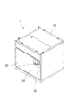
前記各図において本実施形態に係る流体力発電装置1は、ケーシング50を貫通して設けられた流路部51を通る水の流れの力で羽根車10を回転させ、羽根車10から発電機40に駆動力を伝えて発電を行うものであり、河川や用水路等の小規模水路への設置に対応する小型の装置である。
(First embodiment of the present invention)
Hereinafter, the driving force transmission mechanism of the hydrodynamic power generation apparatus according to the first embodiment of the present invention will be described with reference to FIGS. In the present embodiment, an example of a hydroelectric generator that uses the force of water flow as fluid force will be described.
In each of the drawings, the hydrodynamic
より詳細には、流体力発電装置1は、その駆動力伝達機構として、クロスフロー型の羽根車10の回転中心位置で羽根車10と一体に取付けられ、発電装置のケーシング50に回転可能に支持される羽根車軸11と、この羽根車軸11の一端部に直接取付けて配設され、羽根車軸11と連動して回転する駆動プーリ12と、発電機40の入力軸41に直接取付けて配設され、入力軸41と連動して回転する従動プーリ42と、駆動プーリ12と従動プーリ42に巻き掛けられて配設され、駆動プーリ12から従動プーリ42に駆動力を伝達する伝動手段としてのベルト13と、羽根車軸11の一端部寄りとなるケーシング50所定位置に設けられ、駆動プーリ12と羽根車10との間の羽根車軸11所定位置を支持する第一軸受14と、ケーシング50の所定部位で羽根車軸11の他端部を支持する第二軸受15とを備える構成である。
More specifically, the hydrodynamic
この流体力発電装置1は、発電機40を上部、羽根車10を下部にそれぞれ配置して、羽根車軸11が垂直向きとなっている立軸形であり、水の流れ方向に対し横に羽根車10を二つ並べた構造を有し、また、ケーシング50の上部内側に、各羽根車10でそれぞれ駆動される発電機40を横に二つ並べて設けた構成である。
This hydrodynamic
そして、流体力発電装置1は、流れの生じている水中にケーシング50が一部没した状態で設置され、ケーシング50内の流路部51に水流を導くことで、二つ並んだ羽根車10が水流を受けてそれぞれ回転し、各羽根車10から伝達される駆動力で各発電機40を作動させ、発電を行う仕組みである。水は、ケーシング50内の流路部51に前方から流入して、二つの羽根車10をそれぞれ回転させた後、ケーシング後方から出ていくこととなる。ケーシング50の前側には、流路部51の入口側で流路を狭めて水の流速を増大させつつ、水を流路部51中央に案内する絞り部52が設けられる。この絞り部52が、クロスフロー型の各羽根車10に対し、一種のガイドベーンの役割を果している。
The
前記羽根車軸11は、羽根車10の回転中心位置で羽根車10と一体に取付けられ、ケーシング50における流路部51を挟む両側の所定箇所でそれぞれ回転可能に支持される構成である。この羽根車軸11の一端部側所定長さ分が、発電機40への駆動力伝達のために、ケーシング50の流路部51外側となる上側部分に延長配設される。
The
前記駆動プーリ12は、羽根車軸11の一端部に直接取付けて配設され、羽根車軸11と一体に回転する構成である。
前記従動プーリ42は、発電機40の入力軸41に直接取付けて配設され、入力軸41と一体に回転する構成である。この従動プーリ42は、発電機40と共に、羽根車軸11に対し、流体としての水の流れ方向における下流側に位置している。
The
The driven
前記ベルト13は、いわゆるVベルトであり、駆動プーリ12と従動プーリ42に巻き掛けられて配設され、駆動プーリ12の回転に伴わせて従動プーリ42を回転させ、駆動プーリ12から従動プーリ42に駆動力を伝達するものである。
The
前記第一軸受14は、玉軸受等の公知の軸受であり、羽根車軸11の一端部寄りで、且つ前記流路部51の外側となるケーシング50の上部所定位置に設けられ、駆動プーリ12と羽根車10との間の羽根車軸11所定位置を支持するものである(図6、図7参照)。
The
この第一軸受14は、羽根車軸11の回転可能な状態を保持しながら、第二軸受15における羽根車軸支持位置のラジアル方向へのずれに伴う羽根車軸11の傾きを許容する構造とされる。
The
前記第二軸受15は、第一軸受14とは流路部51を挟んで反対側となるケーシング50の流路部51に面する下部に設けられ、羽根車軸11の他端部を支持するものである。この第二軸受15は、ケーシング50側に固定される軸受ハウジング15aと、この軸受ハウジング15aと羽根車軸11他端部との間に介在して、流体としての水と接触する状況下で羽根車軸11の他端部の回動可能状態を維持するブシュ15bとを備える構成である(図7参照)。
The
次に、前記構成に基づく流体力発電装置における軸受摩耗に際してのベルト張力調整状態について説明する。前提として、装置の使用開始状態で各部の摩耗はまだなく、初期の寸法精度が確保され、ベルトも緩み無く適切な張り状態とされているものとする。 Next, the belt tension adjustment state at the time of bearing wear in the hydrodynamic power generation device based on the above configuration will be described. As a premise, it is assumed that there is still no wear of each part in the start of use of the apparatus, the initial dimensional accuracy is ensured, and the belt is in an appropriate tension state without loosening.
発電装置としての使用を継続すると、水中にある第二軸受15でブシュ15b内周部の摩耗や、このブシュ15bと接する羽根車軸11他端部外周の摩耗が進行する。こうした摩耗に伴い、ブシュ15bの内径と羽根車軸11他端部の外径との差が大きくなることで、第二軸受15において、羽根車軸支持位置、すなわち、羽根車軸11とブシュ15bとの実際の摺接位置、のラジアル方向へのずれが生じ得る状態となる。実際の使用では、羽根車10に加わる水流の力で、羽根車軸支持位置は流れの下流側にずれる状態となる(図9参照)。
If the use as the power generation device is continued, the wear of the inner peripheral portion of the
この場合、第一軸受14が、羽根車軸11の傾きを許容する構造を有していることから、羽根車軸11は、羽根車10と共に回転する状態を維持されたまま、第二軸受15における羽根車軸支持位置が水の流れの下流側にずれる分、本来の向きから傾くこととなる。
In this case, since the
羽根車軸11の傾きにより、ケーシング上部に位置する羽根車軸11の一端部は、第一軸受14の位置を基準として、他端部とは逆の、流路部51における水の流れの上流側にずれた状態となる。このずれにより、羽根車軸11の一端部に取付けられた駆動プーリ12も初期状態からずれており、この駆動プーリ12と、羽根車軸11に対し水の流れ方向における下流側に位置している従動プーリ42との距離は初期状態に比べ広がっている(図8、図9参照)。
Due to the inclination of the
このように駆動プーリ12と従動プーリ42との距離が広がることで、駆動プーリ12と従動プーリ42に巻き掛けられているベルト13は、緊張状態となって、駆動プーリ12から従動プーリ42への駆動力の伝達が問題なく行われる状態を維持できることとなる。
As the distance between the
こうして、流路部51を通過する水流が存在する間、水流から羽根車10が受ける力に基づいて羽根車軸11は傾斜し、一端部の駆動プーリ12を従動プーリ42から遠ざけようとする結果、ベルト13の緊張状態が維持され、ベルト13による駆動プーリ12から従動プーリ42への駆動力の適切な伝達が確保される。
In this way, while the water flow passing through the
このように、本実施形態に係る流体力発電装置においては、羽根車軸11をその中間位置で支持する第一軸受14が、羽根車軸11が傾くのを許容すると共に、従動プーリ42を羽根車軸11より水の流れ方向の下流側に位置させて、羽根車10が水流により押されるのに伴って押された側に羽根車軸他端部がずれ、羽根車軸11が傾いた場合に、羽根車軸11の一端部に配置した駆動プーリ12が、従動プーリ42から遠ざかる向きに動くようにしている。
As described above, in the hydrodynamic power generation device according to the present embodiment, the
これにより、常時水中にあって水と接触する状況で軸受として機能するブシュの構造上の特性から、摩耗が生じやすい第二軸受15で、長期にわたる継続使用により、摺接する軸や軸受で摩耗が生じて寸法精度を維持できず、羽根車軸他端部の支持位置のずれと、これに伴う羽根車軸11の傾きと駆動プーリ位置の変位など、ベルト13による駆動力伝達への悪影響が生じ得る状態に至っても、第一軸受14で傾きを許容された羽根車軸11は、第二軸受15での摩耗の分、羽根車10が水流により押される向きに軸他端部をずらして傾いた状態で回転し、羽根車軸11の一端部における駆動プーリ12は、従動プーリ42から遠ざかる向きにずれて、ベルト13の張りを維持しながら回転できることとなり、軸受の摩耗が生じてもベルト13が緩んで駆動力を伝えにくい状態に陥ることがなく、発電機40が適切に駆動され、発電を問題なく継続して行える。
As a result, due to the structural characteristics of the bushing that functions as a bearing when it is always in water and in contact with water, the
(本発明の第2の実施形態)
本発明の第2の実施形態に係る流体力発電装置を前記図10及び図11に基づいて説明する。本実施形態においても、流体力として水流の力を用いる水力発電装置の例について説明する。
前記各図において本実施形態に係る流体力発電装置は、駆動力伝達機構として、前記第1の実施形態と同様、羽根車軸21と、駆動プーリ23と、従動プーリ42と、ベルト24と、第一軸受25と、第二軸受26とを備える一方、異なる点として、羽根車軸21の一端部に、羽根車20の回転を増速した状態で駆動プーリ23に伝える増速機構22を配設し、この増速機構22上に駆動プーリ23を回転可能に支持する構成を有するものである。
なお、増速機構22と、この増速機構に駆動プーリ23が支持される点以外の構成については、前記第1の実施形態と同じであり、詳細な説明を省略する。
(Second embodiment of the present invention)
A hydrodynamic power generation apparatus according to a second embodiment of the present invention will be described with reference to FIGS. Also in this embodiment, an example of a hydroelectric power generation apparatus that uses the force of water flow as fluid force will be described.
In each of the drawings, the hydrodynamic power generation device according to the present embodiment has the
The configuration other than the
前記増速機構22は、羽根車軸21の一端部に、羽根車20の回転を増速した状態で駆動プーリ23に伝える機構であり、羽根車軸21に対し相対回転可能として配設される。この増速機構22上に、駆動プーリ23が羽根車軸21と一致しない他の軸(出力軸)を中心として回転可能に支持されることとなる。
この増速機構22は、入力軸である羽根車軸21の回転を内蔵の歯車列を介して増速した上で、出力軸に伝達し、出力軸上の駆動プーリ23を回転させる公知の機構であり、詳細な説明を省略する。
The
The
そして、増速機構22は、羽根車軸21が回転すると、増速機構22に対し外部から所定の拘束力を加えない場合、機構内部の摩擦等による抵抗があることから、羽根車軸21に対し相対回転せず、羽根車軸21と共回りする状態となる。
When the
この増速機構22と、羽根車軸21、及び、駆動プーリ23との位置関係は、仮にベルト24の巻き掛けによる拘束を受けずに、増速機構22が羽根車軸21と一体に回転することを想定した場合に、増速機構22の回転開始に伴って、増速機構22上の駆動プーリ23を発電機40側の従動プーリ42から遠ざける状態となるように、羽根車軸21に対する増速機構22の配設の向きを設定することとなる。
The positional relationship between the
より具体的には、例えば、羽根車20及び羽根車軸21の回転方向が装置上方から見て時計回りの場合、羽根車軸21が発電機40より手前となる側から見て、羽根車軸21と発電機40の入力軸41とを結んだ線より右側の領域に、増速機構22上の駆動プーリ23中心が位置するように、ベルト24を巻掛けた状態での増速機構22の羽根車軸21に対する向きを設定する(図10参照)。
More specifically, for example, when the rotation direction of the
次に、前記構成に基づく流体力発電装置における駆動力伝達に際してのベルト張力調整状態について説明する。前提として、装置の使用開始時点では増速機構22上の駆動プーリ23と発電機40側の従動プーリ42との間にベルト24が所定の張り状態で巻き掛けられて、緩みによる各プーリからのベルト24の脱落が生じないようにされているものとする。
Next, the belt tension adjustment state at the time of driving force transmission in the hydrodynamic power generation device based on the above configuration will be described. As a premise, the
ケーシング50の流路部51に水を導入して羽根車20を回転開始させると、ケーシング側に固定されていない増速機構22が、羽根車軸21の回転に合わせて共に回転しようとし、増速機構22上の駆動プーリ23も一体に回転して、発電機側の従動プーリ42から遠ざかろうとする。
When water is introduced into the
こうして、羽根車軸21の回転につれて増速機構22及び駆動プーリ23も同じ向きに回転しようとするのに伴い、駆動プーリ23が従動プーリ42から遠ざかろうとして、これらの間に巻き掛けられたベルト24を緊張させることとなる。駆動プーリ23はベルト24による拘束で羽根車軸21周りの回転を止められ、これにより増速機構22も回転を制限されて、増速機構22に対し羽根車軸21が回転し、増速機構22は羽根車軸21の回転を増速しつつ駆動プーリ23に伝える状態に移行する。
Thus, as the
駆動プーリ23の回転がベルト24を介して従動プーリ42に伝わり、発電機40が駆動されて発電を行う中、ベルト24の存在で拘束されてはいるものの、増速機構22が羽根車軸21と共に回転しようとして所定のトルクを生じている状態は羽根車軸21の回転当初から変らないため、ベルト24には常に適度な緊張力が加わる状態となっており、羽根車軸21が回転する間、ベルト24に緩みが生じることはなく、ベルト24を介して確実に発電機40を駆動でき、発電機40で効率よく発電を行わせることができる。
While the rotation of the
また、羽根車20が起動するとベルト24が適切な緊張状態へ移行するのを、増速機構22の羽根車軸21に対する配置のみで実現していることで、ベルト24の張り具合を調整する機構を別途必要とせず、羽根車軸21から発電機40への駆動力の伝達機構を簡略に構成できる。
In addition, when the
さらに、長期の使用で、水中にある第二軸受での各部の摩耗が進行した場合でも、前記第1の実施形態と同様、羽根車軸21の傾きにより、ケーシング上部に位置する羽根車軸の一端部は、流路部51における水の流れの上流側にずれた状態となり(図9参照)、駆動プーリ23と従動プーリ42との距離を広げるようにして、ベルト24を緊張した状態に維持でき、ベルト24による駆動プーリ23から従動プーリ42への駆動力の伝達は確保されることとなる。
Further, even when the wear of each part of the second bearing underwater has progressed over a long period of use, the one end part of the impeller shaft located at the upper part of the casing due to the inclination of the
このように、本実施形態に係る流体力発電装置の駆動力伝達機構においては、駆動プーリ23を含む増速機構22の、羽根車軸21と共回りする際の動きが、駆動プーリ23が発電機側の従動プーリ42から遠ざかる状態となる配置で、増速機構22の羽根車軸21に対する位置を設定しつつ、駆動プーリ23と従動プーリ42とをベルト24で連動させることから、羽根車軸21の回転につれて増速機構22も同じ向きに回転しようとするのに伴い、駆動プーリ23が従動プーリ42から離れようとして、これらの間に巻き掛けられたベルト24を緊張させることとなり、ベルト24には常に適度な緊張力が加わる状態となって、ベルト24の緩みを生じさせず、仮にベルトが経年変化で伸びたとしてもその伸び分も吸収して緊張を維持でき、ベルト24で確実に発電機側に駆動力を伝えて、発電機40を継続的に効率よく作動させられる。
Thus, in the driving force transmission mechanism of the hydrodynamic power generation device according to the present embodiment, the movement of the
なお、前記各実施形態に係る流体力発電装置においては、伝動手段をベルトとし、羽根車軸又は増速機構からベルトに駆動力を伝える機械要素を駆動プーリ、ベルトから発電機の入力軸に駆動力を伝える機械要素を従動プーリとする構成としているが、これに限らず、伝動手段をチェーンとし、羽根車軸又は増速機構からチェーンに駆動力を伝えるのに駆動スプロケット、チェーンから発電機の入力軸に駆動力を伝えるのに従動スプロケットをそれぞれ用いる構成とすることもできる。こうしたチェーン等を用いる場合も、前記各実施形態同様、羽根車軸の一端部における駆動スプロケットが、従動スプロケットから遠ざかる向きにずれて、チェーンの張りを維持できることとなり、チェーンが緩んで駆動力を伝えにくい状態に陥ることがなく、発電機40が適切に駆動され、発電を継続できる。
In the hydrodynamic power generation apparatus according to each of the embodiments described above, the transmission means is a belt, the mechanical element that transmits the driving force from the impeller shaft or the speed increasing mechanism to the belt is a driving pulley, and the driving force is transmitted from the belt to the input shaft of the generator. However, the drive element is not limited to this, and the transmission means is a chain, and the drive sprocket is used to transmit the driving force from the impeller shaft or the speed increasing mechanism to the chain. It is also possible to employ a configuration in which driven sprockets are used to transmit the driving force to each. Even when such a chain is used, the driving sprocket at one end portion of the impeller shaft is displaced away from the driven sprocket so that the tension of the chain can be maintained, and the chain is loosened so that the driving force is not easily transmitted. Without falling into a state, the
また、前記各実施形態に係る流体力発電装置においては、発電機40の入力軸41に直接従動プーリ42が取付けられ、羽根車側から伝えられた駆動力を従動プーリ42から減速又は増速することなく発電機40に伝える構成としているが、これに限らず、従動プーリと発電機40の入力軸41との間に、減速機構又は増速機構を介在させ、従動プーリの回転を減速又は増速した状態で発電機40に伝える構成とすることもできる。この場合、減速機構又は増速機構上に回転可能に支持される従動プーリの位置が変化して、ベルト等の伝動手段の張り具合が緩み側に変化するのを防ぐため、減速機構又は増速機構は、ケーシングに固定された状態で設けるのが好ましい。
Further, in the fluid power generation device according to each of the embodiments, the driven
また、前記各実施形態に係る流体力発電装置においては、発電機40をケーシング50上部に配置し、その下側の流路部51に羽根車10を位置させ、羽根車軸11を垂直向きとした立軸形の構成としているが、これに限らず、羽根車軸が横向きとなり、流路部外側で羽根車の側方となる位置に駆動プーリ等の駆動力伝達機構が配置される、横軸形の構成とすることもでき、河川や水路をはじめとする発電装置の設置箇所の状況や発電機の形状等に応じて、装置のレイアウトを適宜選択できる。
Further, in the hydrodynamic power generation device according to each of the above embodiments, the
加えて、流路部51を通る流体の流れの力でクロスフロー型の羽根車10を回転させるものへの適用以外に、閉じた領域としての流路部ではなく開放された空間部分を通って羽根車に達する流体の流れの力で羽根車を回転させる、ペルトン水車や開放型上掛水車、開放型下掛水車などを含む、ケーシングに軸支された羽根車の羽根又はランナに加わる流体の流れの力で羽根車を回転させ、羽根車から発電機に駆動力を伝えて発電を行う他の流体力発電装置にも適用することができ、羽根車軸の傾きを許容して、羽根車軸上の駆動プーリ又はスプロケットが発電機側の従動プーリ又はスプロケットから遠ざかる向きへ動くようにしたり、回転する羽根車軸に対して減速機構又は増速機構上の駆動プーリ又はスプロケットが発電機側の従動プーリ又はスプロケットから遠ざかる状態となるように、減速機構又は増速機構の配設の向きを設定したりすることで、前記実施形態同様、ベルト等の緩みを生じさせず、確実に発電機側に駆動力を伝えて、発電機を継続的に効率よく作動させられることとなる。
In addition to the application to the one that rotates the
さらに、前記各実施形態に係る流体力発電装置においては、流体力として水流の力を用いる構成としているが、これに限らず、水以外の他の液体や、気体、一種の流体としての性質を示す多量の粒状体などの流れの力、あるいは、気体と液体と固体のいずれか二種又は三種の混相流の流れの力、を用いる構成とすることもでき、前記各実施形態同様、流れの力を羽根車で受けて羽根車を回転させ、得られた駆動力を発電機に伝えて効率よく発電を行うことができる。 Furthermore, in the hydroelectric power generation apparatus according to each of the above embodiments, the structure uses a water flow force as the fluid force. However, the present invention is not limited to this, and has properties as a liquid other than water, a gas, or a kind of fluid. The flow force of a large amount of granular materials or the like, or the flow force of any two or three mixed-phase flows of gas, liquid, and solid can be used. Power can be received by the impeller to rotate the impeller, and the obtained driving force can be transmitted to the generator for efficient power generation.
1 流体力発電装置
10、20 羽根車
11、21 羽根車軸
11a 開口部
12、23 駆動プーリ
13、24 ベルト
14、25 第1軸受
15、26 第2軸受
15a 軸受ハウジング
15b ブシュ
22 増速機構
40 発電機
41 入力軸
42 従動プーリ
50 ケーシング
51 流路部
52 絞り部
DESCRIPTION OF
Claims (2)
羽根車の回転中心位置で羽根車と一体に取付けられ、ケーシングにおける前記流路部を挟む両側の所定箇所でそれぞれ回転可能に支持される羽根車軸と、
ケーシングの流路部外側となる部分に延長配設された前記羽根車軸の一方の端部に、直接取付けて、又は、減速機構もしくは増速機構を介在させて配設され、少なくとも前記羽根車軸と連動して回転する状態とされる、駆動プーリ又はスプロケットと、
前記発電機の入力軸に、直接取付けて、又は、減速機構もしくは増速機構を介在させて配設され、少なくとも前記入力軸と連動して回転する状態とされる、従動プーリ又はスプロケットと、
前記駆動プーリ又はスプロケットと前記従動プーリ又はスプロケットに巻き掛けられて配設され、前記駆動プーリ又はスプロケットから、前記従動プーリ又はスプロケットに駆動力を伝達する無端の伝動手段と、
前記羽根車軸の一方の端部寄りで、且つ前記流路部の外側となるケーシングの所定位置に設けられ、前記駆動プーリ又はスプロケットと前記羽根車との間の羽根車軸所定位置を支持する第一の軸受と、
当該第一の軸受とは流路部を挟んで反対側となるケーシングの流路部に面する所定部位に設けられ、前記羽根車軸の他方の端部を支持する第二の軸受とを備え、
前記第二の軸受が、ケーシングに固定されるハウジング部と、当該ハウジング部と羽根車軸他端部との間に介在して、羽根車軸の他端部の回動可能状態を維持するブシュとを有し、
前記第一の軸受が、前記第二の軸受における羽根車軸支持位置のラジアル方向へのずれに伴う羽根車軸の傾きを許容する構造とされ、
前記羽根車軸、第一の軸受、及び第二の軸受が、前記従動プーリ又はスプロケットに対し、流体の流れ方向における上流側に位置することを
特徴とする流体力発電装置。 In the hydrodynamic power generation device that rotates the impeller with the force of the flow of fluid passing through the flow path provided through the casing and transmits the driving force from the impeller to the generator to generate power,
An impeller mounted integrally with the impeller at the rotational center position of the impeller, and supported rotatably at predetermined locations on both sides of the flow passage portion in the casing;
It is directly attached to one end portion of the impeller shaft that is extended and disposed on a portion that is outside the flow path portion of the casing, or is disposed with a speed reduction mechanism or a speed increasing mechanism interposed, and at least the impeller shaft A driving pulley or sprocket which is in a state of rotating in conjunction with it;
A driven pulley or a sprocket that is directly attached to the input shaft of the generator, or is disposed with a speed reduction mechanism or a speed increasing mechanism interposed, and is in a state of rotating in conjunction with at least the input shaft;
An endless transmission means arranged to be wound around the driving pulley or sprocket and the driven pulley or sprocket, and transmitting a driving force from the driving pulley or sprocket to the driven pulley or sprocket;
A first shaft is provided at a predetermined position of the casing near one end of the impeller shaft and outside the flow path portion, and supports a predetermined position of the impeller shaft between the drive pulley or sprocket and the impeller. Bearings,
The first bearing is provided at a predetermined portion facing the flow passage portion of the casing on the opposite side across the flow passage portion, and includes a second bearing that supports the other end portion of the impeller shaft,
A housing portion fixed to the casing; and a bushing interposed between the housing portion and the other end portion of the impeller shaft to maintain a rotatable state of the other end portion of the impeller shaft. Have
The first bearing is configured to allow the inclination of the impeller shaft accompanying the radial shift of the impeller shaft support position in the second bearing,
The hydrodynamic power generation device, wherein the impeller shaft, the first bearing, and the second bearing are located upstream of the driven pulley or sprocket in a fluid flow direction.
前記羽根車軸の一方の端部に、羽根車の回転を減速又は増速した状態で前記駆動プーリ又はスプロケットに伝える減速機構又は増速機構が、羽根車軸及び前記ケーシングに対し相対回転可能として配設され、
前記駆動プーリ又はスプロケットは、前記減速機構又は増速機構上に、前記羽根車軸と一致しない他の軸を中心として回転可能に支持され、
羽根車軸と、減速機構又は増速機構と、駆動プーリ又はスプロケットとの各位置関係が、減速機構又は増速機構が羽根車軸に対し相対回転せず羽根車軸と一体に回転して共回りすると、当該回転共回りの開始時に、減速機構又は増速機構上の駆動プーリ又はスプロケットを発電機側の従動プーリ又はスプロケットから遠ざけて伝動手段を緊張させる状態となるように、羽根車軸に対する減速機構又は増速機構の配設の向きを設定することを
特徴とする流体力発電装置。 In the fluid power generation device according to claim 1,
At one end of the impeller shaft, a speed reduction mechanism or speed increasing mechanism for transmitting the rotation of the impeller to the drive pulley or sprocket in a state where the rotation of the impeller is decelerated or increased is arranged to be rotatable relative to the impeller shaft and the casing. And
The drive pulley or sprocket is supported on the speed reduction mechanism or speed increasing mechanism so as to be rotatable around another axis that does not coincide with the impeller shaft,
An impeller shaft, a reduction gear mechanism or the speed increasing mechanism, the positional relationship between the drive pulley or sprocket, the deceleration mechanism or the speed increasing mechanism is rotated together with rotation to the impeller shaft and integrally without relative rotation with respect to the impeller shaft , at the start of the rotation both around, so that the state of Ru is tensioned transmission means a drive pulley or sprocket on the speed reduction mechanism or the speed increasing mechanism away from the driven pulley or sprocket on the generator side, the deceleration mechanism for the impeller shaft Or the direction of arrangement | positioning of a speed-up mechanism is set, The fluid power generator characterized by the above-mentioned.
Priority Applications (1)
| Application Number | Priority Date | Filing Date | Title |
|---|---|---|---|
| JP2012276833A JP5919590B2 (en) | 2012-12-19 | 2012-12-19 | Fluid power generator |
Applications Claiming Priority (1)
| Application Number | Priority Date | Filing Date | Title |
|---|---|---|---|
| JP2012276833A JP5919590B2 (en) | 2012-12-19 | 2012-12-19 | Fluid power generator |
Publications (2)
| Publication Number | Publication Date |
|---|---|
| JP2014118937A JP2014118937A (en) | 2014-06-30 |
| JP5919590B2 true JP5919590B2 (en) | 2016-05-18 |
Family
ID=51173973
Family Applications (1)
| Application Number | Title | Priority Date | Filing Date |
|---|---|---|---|
| JP2012276833A Expired - Fee Related JP5919590B2 (en) | 2012-12-19 | 2012-12-19 | Fluid power generator |
Country Status (1)
| Country | Link |
|---|---|
| JP (1) | JP5919590B2 (en) |
Cited By (1)
| Publication number | Priority date | Publication date | Assignee | Title |
|---|---|---|---|---|
| KR102252874B1 (en) * | 2021-01-19 | 2021-05-17 | 주식회사 코다코 | Small hydropower generation apparatus |
Families Citing this family (1)
| Publication number | Priority date | Publication date | Assignee | Title |
|---|---|---|---|---|
| CN109578189B (en) * | 2018-09-11 | 2023-12-15 | 华北水利水电大学 | Three-stage chain wheel and chain transmission type ecological fish-passing water turbine |
Family Cites Families (4)
| Publication number | Priority date | Publication date | Assignee | Title |
|---|---|---|---|---|
| JPS63183497U (en) * | 1987-05-19 | 1988-11-25 | ||
| JPH09256941A (en) * | 1996-03-25 | 1997-09-30 | Osamu Inoue | Curved water-turbine-blade type hydraulic power generation mechanism |
| CZ302396B6 (en) * | 2007-08-03 | 2011-04-27 | Ceské vysoké ucení technické, Fakulta stavební | Fluid turbine |
| WO2010086958A1 (en) * | 2009-01-27 | 2010-08-05 | シーベルインターナショナル株式会社 | Hydraulic power generation device |
-
2012
- 2012-12-19 JP JP2012276833A patent/JP5919590B2/en not_active Expired - Fee Related
Cited By (1)
| Publication number | Priority date | Publication date | Assignee | Title |
|---|---|---|---|---|
| KR102252874B1 (en) * | 2021-01-19 | 2021-05-17 | 주식회사 코다코 | Small hydropower generation apparatus |
Also Published As
| Publication number | Publication date |
|---|---|
| JP2014118937A (en) | 2014-06-30 |
Similar Documents
| Publication | Publication Date | Title |
|---|---|---|
| JP4817471B1 (en) | Hydroelectric generator | |
| JP4956537B2 (en) | Power generation equipment that generates electricity by water flow such as tidal currents, river flows, etc. | |
| AU2008239143B2 (en) | Hydraulic power generating apparatus | |
| JP5551594B2 (en) | Device and method for converting kinetic energy of running water into kinetic energy of rotating rotor shaft | |
| US8616830B2 (en) | Hydraulic power generating apparatus | |
| JP5919590B2 (en) | Fluid power generator | |
| TW201250111A (en) | Water wheel impeller blade type electric power generating apparatus | |
| GB2435908A (en) | Vertical axis turbine for low speed flows with stall prevention | |
| JP5919596B2 (en) | Hydroelectric generator | |
| JP2013024049A (en) | Small-scaled hydropower generation apparatus | |
| JP5702781B2 (en) | Wave tidal power plant and method | |
| WO2010086958A1 (en) | Hydraulic power generation device | |
| JP2006507448A (en) | Hydraulic wheel | |
| JP2009174480A (en) | Impeller for undershot water wheel and undershot water wheel device | |
| KR101852023B1 (en) | Hydraulic turbine and hydraulic power generation system including the same | |
| JP4917690B1 (en) | Running water power generator | |
| WO2013051113A1 (en) | Francis turbine for hydropower generation | |
| JP4665387B2 (en) | Hydroelectric generator | |
| JP3993220B1 (en) | Water turbine for power generation | |
| JP4955939B2 (en) | Water wheel drive | |
| WO2014112200A1 (en) | Undershot water wheel | |
| KR20100118673A (en) | Turbine for a hydroelectric power station | |
| US1197761A (en) | Hydraulic turbine. | |
| JP2015140662A (en) | Hydraulic generating apparatus | |
| KR101493005B1 (en) | Flow energy harvesting apparatus by adjusting conditions of drainage pipe |
Legal Events
| Date | Code | Title | Description |
|---|---|---|---|
| A621 | Written request for application examination |
Free format text: JAPANESE INTERMEDIATE CODE: A621 Effective date: 20140905 |
|
| A977 | Report on retrieval |
Free format text: JAPANESE INTERMEDIATE CODE: A971007 Effective date: 20150723 |
|
| A131 | Notification of reasons for refusal |
Free format text: JAPANESE INTERMEDIATE CODE: A131 Effective date: 20150804 |
|
| A521 | Request for written amendment filed |
Free format text: JAPANESE INTERMEDIATE CODE: A523 Effective date: 20151001 |
|
| TRDD | Decision of grant or rejection written | ||
| A01 | Written decision to grant a patent or to grant a registration (utility model) |
Free format text: JAPANESE INTERMEDIATE CODE: A01 Effective date: 20160216 |
|
| A521 | Request for written amendment filed |
Free format text: JAPANESE INTERMEDIATE CODE: A523 Effective date: 20160318 |
|
| A61 | First payment of annual fees (during grant procedure) |
Free format text: JAPANESE INTERMEDIATE CODE: A61 Effective date: 20160317 |
|
| A521 | Request for written amendment filed |
Free format text: JAPANESE INTERMEDIATE CODE: A821 Effective date: 20160318 |
|
| R150 | Certificate of patent or registration of utility model |
Ref document number: 5919590 Country of ref document: JP Free format text: JAPANESE INTERMEDIATE CODE: R150 |
|
| R250 | Receipt of annual fees |
Free format text: JAPANESE INTERMEDIATE CODE: R250 |
|
| LAPS | Cancellation because of no payment of annual fees |