JP5918314B2 - A silencer for the main body that forms a tubular cavity - Google Patents
A silencer for the main body that forms a tubular cavity Download PDFInfo
- Publication number
- JP5918314B2 JP5918314B2 JP2014144766A JP2014144766A JP5918314B2 JP 5918314 B2 JP5918314 B2 JP 5918314B2 JP 2014144766 A JP2014144766 A JP 2014144766A JP 2014144766 A JP2014144766 A JP 2014144766A JP 5918314 B2 JP5918314 B2 JP 5918314B2
- Authority
- JP
- Japan
- Prior art keywords
- silencer
- tubular body
- insert
- coolant circuit
- motomeko
- Prior art date
- Legal status (The legal status is an assumption and is not a legal conclusion. Google has not performed a legal analysis and makes no representation as to the accuracy of the status listed.)
- Expired - Fee Related
Links
- 230000003584 silencer Effects 0.000 title claims description 64
- 239000002826 coolant Substances 0.000 claims description 19
- 238000001816 cooling Methods 0.000 claims description 10
- 239000000463 material Substances 0.000 claims description 10
- 238000005192 partition Methods 0.000 claims description 9
- 238000010521 absorption reaction Methods 0.000 description 3
- 238000004519 manufacturing process Methods 0.000 description 3
- 230000035515 penetration Effects 0.000 description 3
- 230000004323 axial length Effects 0.000 description 2
- 238000005452 bending Methods 0.000 description 2
- 238000002347 injection Methods 0.000 description 2
- 239000007924 injection Substances 0.000 description 2
- 238000003780 insertion Methods 0.000 description 2
- 230000037431 insertion Effects 0.000 description 2
- 238000009434 installation Methods 0.000 description 2
- 230000006978 adaptation Effects 0.000 description 1
- 229910052782 aluminium Inorganic materials 0.000 description 1
- XAGFODPZIPBFFR-UHFFFAOYSA-N aluminium Chemical compound [Al] XAGFODPZIPBFFR-UHFFFAOYSA-N 0.000 description 1
- 239000011324 bead Substances 0.000 description 1
- 238000002485 combustion reaction Methods 0.000 description 1
- 230000007423 decrease Effects 0.000 description 1
- 238000010586 diagram Methods 0.000 description 1
- 239000012530 fluid Substances 0.000 description 1
- 238000009413 insulation Methods 0.000 description 1
- 229910052751 metal Inorganic materials 0.000 description 1
- 239000002184 metal Substances 0.000 description 1
- 125000006850 spacer group Chemical group 0.000 description 1
Images


Classifications
-
- F—MECHANICAL ENGINEERING; LIGHTING; HEATING; WEAPONS; BLASTING
- F16—ENGINEERING ELEMENTS AND UNITS; GENERAL MEASURES FOR PRODUCING AND MAINTAINING EFFECTIVE FUNCTIONING OF MACHINES OR INSTALLATIONS; THERMAL INSULATION IN GENERAL
- F16L—PIPES; JOINTS OR FITTINGS FOR PIPES; SUPPORTS FOR PIPES, CABLES OR PROTECTIVE TUBING; MEANS FOR THERMAL INSULATION IN GENERAL
- F16L55/00—Devices or appurtenances for use in, or in connection with, pipes or pipe systems
- F16L55/02—Energy absorbers; Noise absorbers
- F16L55/033—Noise absorbers
-
- F—MECHANICAL ENGINEERING; LIGHTING; HEATING; WEAPONS; BLASTING
- F01—MACHINES OR ENGINES IN GENERAL; ENGINE PLANTS IN GENERAL; STEAM ENGINES
- F01N—GAS-FLOW SILENCERS OR EXHAUST APPARATUS FOR MACHINES OR ENGINES IN GENERAL; GAS-FLOW SILENCERS OR EXHAUST APPARATUS FOR INTERNAL COMBUSTION ENGINES
- F01N1/00—Silencing apparatus characterised by method of silencing
- F01N1/02—Silencing apparatus characterised by method of silencing by using resonance
- F01N1/026—Annular resonance chambers arranged concentrically to an exhaust passage and communicating with it, e.g. via at least one opening in the exhaust passage
-
- F—MECHANICAL ENGINEERING; LIGHTING; HEATING; WEAPONS; BLASTING
- F01—MACHINES OR ENGINES IN GENERAL; ENGINE PLANTS IN GENERAL; STEAM ENGINES
- F01N—GAS-FLOW SILENCERS OR EXHAUST APPARATUS FOR MACHINES OR ENGINES IN GENERAL; GAS-FLOW SILENCERS OR EXHAUST APPARATUS FOR INTERNAL COMBUSTION ENGINES
- F01N1/00—Silencing apparatus characterised by method of silencing
- F01N1/02—Silencing apparatus characterised by method of silencing by using resonance
- F01N1/023—Helmholtz resonators
-
- F—MECHANICAL ENGINEERING; LIGHTING; HEATING; WEAPONS; BLASTING
- F04—POSITIVE - DISPLACEMENT MACHINES FOR LIQUIDS; PUMPS FOR LIQUIDS OR ELASTIC FLUIDS
- F04B—POSITIVE-DISPLACEMENT MACHINES FOR LIQUIDS; PUMPS
- F04B39/00—Component parts, details, or accessories, of pumps or pumping systems specially adapted for elastic fluids, not otherwise provided for in, or of interest apart from, groups F04B25/00 - F04B37/00
-
- F—MECHANICAL ENGINEERING; LIGHTING; HEATING; WEAPONS; BLASTING
- F16—ENGINEERING ELEMENTS AND UNITS; GENERAL MEASURES FOR PRODUCING AND MAINTAINING EFFECTIVE FUNCTIONING OF MACHINES OR INSTALLATIONS; THERMAL INSULATION IN GENERAL
- F16L—PIPES; JOINTS OR FITTINGS FOR PIPES; SUPPORTS FOR PIPES, CABLES OR PROTECTIVE TUBING; MEANS FOR THERMAL INSULATION IN GENERAL
- F16L55/00—Devices or appurtenances for use in, or in connection with, pipes or pipe systems
- F16L55/02—Energy absorbers; Noise absorbers
- F16L55/033—Noise absorbers
- F16L55/0331—Noise absorbers by inserting an elongated element in the pipe
-
- F—MECHANICAL ENGINEERING; LIGHTING; HEATING; WEAPONS; BLASTING
- F01—MACHINES OR ENGINES IN GENERAL; ENGINE PLANTS IN GENERAL; STEAM ENGINES
- F01N—GAS-FLOW SILENCERS OR EXHAUST APPARATUS FOR MACHINES OR ENGINES IN GENERAL; GAS-FLOW SILENCERS OR EXHAUST APPARATUS FOR INTERNAL COMBUSTION ENGINES
- F01N2490/00—Structure, disposition or shape of gas-chambers
- F01N2490/15—Plurality of resonance or dead chambers
- F01N2490/155—Plurality of resonance or dead chambers being disposed one after the other in flow direction
-
- F—MECHANICAL ENGINEERING; LIGHTING; HEATING; WEAPONS; BLASTING
- F01—MACHINES OR ENGINES IN GENERAL; ENGINE PLANTS IN GENERAL; STEAM ENGINES
- F01N—GAS-FLOW SILENCERS OR EXHAUST APPARATUS FOR MACHINES OR ENGINES IN GENERAL; GAS-FLOW SILENCERS OR EXHAUST APPARATUS FOR INTERNAL COMBUSTION ENGINES
- F01N2490/00—Structure, disposition or shape of gas-chambers
- F01N2490/20—Chambers being formed inside the exhaust pipe without enlargement of the cross section of the pipe, e.g. resonance chambers
Landscapes
- Engineering & Computer Science (AREA)
- General Engineering & Computer Science (AREA)
- Mechanical Engineering (AREA)
- Chemical & Material Sciences (AREA)
- Combustion & Propulsion (AREA)
- Pipe Accessories (AREA)
- Exhaust Silencers (AREA)
- Soundproofing, Sound Blocking, And Sound Damping (AREA)
- Compressor (AREA)
Description
本発明は、消音器が挿入される管状の本体を有する冷却系の冷却剤回路に関する。 The present invention relates to a coolant circuit of a cooling system having a tubular body into which a silencer is inserted.
パイプ用の共鳴器型消音器が、例えば特許文献1から既知である。同心円状に位置付けられた複数の消音チャンバを有し、高温ガスが流れるパイプ用の消音器がこの公開文献から既知である。 A resonator-type silencer for pipes is known, for example, from US Pat. A silencer for a pipe having a plurality of silencer chambers positioned concentrically and through which hot gas flows is known from this publication.
特許文献2は、複数の共鳴器チャンバを有する音響共鳴器を記載している。共鳴器チャンバは、パイプの内周部に沿って又は外周部に位置付けることができる。
パイプの外周部に位置付けられる共鳴器チャンバを有する別の消音器が、特許文献3から既知である。 Another silencer with a resonator chamber located at the outer periphery of the pipe is known from US Pat.
上述の消音器は、製造するのに複雑であり費用がかかるという欠点を有する。加えて、これらの消音器は、特に自動車産業の用途では有効でないことが多い大きな設置空間を必要とする。 The silencers described above have the disadvantage that they are complicated and expensive to manufacture. In addition, these silencers require a large installation space that is often not effective, especially in the automotive industry.
特許文献4は、燃焼機関の吸気系用の消音器を記載している。
本発明の目的は、冷却系の遮音性を改善することである。 The object of the present invention is to improve the sound insulation of the cooling system.
この目的は、消音器が挿入される管状の本体を有する冷却系の冷却剤回路であって、管状の本体は空洞を形成し、消音器は、当該管状の本体の空洞に挿入されるインサートとして設計され、当該インサートは少なくとも1つの共鳴器チャンバと流路とを区切り、当該流路は、接続チャネルを介して共鳴器チャネルに接続されている、冷却剤回路によって達成される。 The purpose of this is a cooling system coolant circuit having a tubular body into which a silencer is inserted, the tubular body forming a cavity, the silencer being used as an insert to be inserted into the cavity of the tubular body. Designed, the insert delimits at least one resonator chamber and a flow path, which is achieved by a coolant circuit that is connected to the resonator channel via a connection channel.
この設計は、音響共鳴器の原理を用いて効果的な騒音吸収を可能にしている。共鳴器チャンバ内に含まれているガス容積は、好ましくは、狭い接続チャネルを介して流路に接続される。明確な自然共鳴を有する機械的ばね質量系が、接続チャネルに位置するガスの不活性質量と組み合わせられた共鳴器チャンバの内部のガス容量の弾性に起因して生じる。騒音の発生は、この自然共鳴により効果的に低減することができる。騒音源の周波数が分かっている場合、共鳴器チャンバの固有振動数をこの周波数に合わせて調整することができる。異なる周波数帯域の騒音の吸収を可能にするには、複数の共鳴器チャンバ(それぞれが異なる固有振動数を有する)を設けることもできる。本発明によれば、消音器はインサートとして設計され、インサートは少なくとも1つの共鳴器チャンバ及び流路を形成する。このようにして、消音器は特に容易に製造可能である。インサートを管状の本体内に配置するだけで十分である。管状の本体への更なる適合が絶対に必要であるとは限らない。さらに、消音器は、管状の本体の外部に更なる任意の設置空間を必要としない。このようにして、消音器は別個に製造され、管状の本体に挿入される必要があるだけなので、組付けは特に容易に実行することができる。インサートとしての消音器の設計に起因して製造コストも低い。このタイプの消音器は、少なくとも部分的にガスが流れる管状の本体に特に適している。消音器は冷却回路のような閉回路系に特に適している。インサートは、コンプレッサの騒音を効果的に減衰させるために、冷却系の冷却回路に挿入される。消音器は、例えば自動車における移動式冷却系に特に適している。本発明による消音器は、冷却系の冷却剤回路に挿入される管状の本体を有する。管状の本体は、剛性又は可撓性の設計を有することができる。管状の本体は有利には、例えばプラスチック製のフレキシブルホースである。 This design enables effective noise absorption using the principle of acoustic resonators. The gas volume contained within the resonator chamber is preferably connected to the flow path via a narrow connection channel. A mechanical spring mass system with clear natural resonance results from the elasticity of the gas volume inside the resonator chamber combined with the inert mass of the gas located in the connecting channel. Generation of noise can be effectively reduced by this natural resonance. If the frequency of the noise source is known, the natural frequency of the resonator chamber can be adjusted to this frequency. To allow absorption of noise in different frequency bands, a plurality of resonator chambers (each having a different natural frequency) can be provided. According to the invention, the silencer is designed as an insert, which forms at least one resonator chamber and a flow path. In this way, the silencer can be manufactured particularly easily. It is sufficient to place the insert in the tubular body. Further adaptation to the tubular body is not absolutely necessary. Furthermore, the silencer does not require any additional installation space outside the tubular body. In this way, the assembly can be performed particularly easily since the silencer has to be manufactured separately and only needs to be inserted into the tubular body. Due to the design of the silencer as an insert, the manufacturing cost is also low. This type of silencer is particularly suitable for tubular bodies through which gas flows at least partially. The silencer is particularly suitable for closed circuit systems such as cooling circuits. The insert is inserted into the cooling circuit of the cooling system to effectively attenuate the compressor noise. The silencer is particularly suitable for mobile cooling systems, for example in automobiles. The silencer according to the invention has a tubular body that is inserted into the coolant circuit of the cooling system. The tubular body can have a rigid or flexible design. The tubular body is preferably a flexible hose, for example made of plastic.
本発明の有利な実施の形態によれば、インサートが、流路を形成するとともに当該流路を少なくとも1つの共鳴器チャンバから分離する隔壁を有するということが提供される。隔壁はここでは、内側パイプを形成するインサートの部分によって形成することができる。このようにして、容易に製造及び組付けを行うことができる消音器が得られる。内側パイプは、消音器の内部に流路を形成する。これは、管状の本体内に同軸に配置することができる。内側パイプは、丸いか又は角のある断面を有することができる。流路は、好適には、内側パイプの内部に位置付けられ、少なくとも1つの共鳴器チャンバは、内側パイプの外部であって、内側パイプと管状の本体との間に形成される空間に形成される。 According to an advantageous embodiment of the invention, it is provided that the insert has a partition which forms a flow path and separates the flow path from at least one resonator chamber. The septum can here be formed by the part of the insert that forms the inner pipe. In this way, a silencer that can be easily manufactured and assembled is obtained. The inner pipe forms a flow path inside the silencer. This can be arranged coaxially within the tubular body. The inner pipe can have a round or angular cross section. The flow path is preferably located inside the inner pipe and the at least one resonator chamber is formed in the space formed outside the inner pipe and between the inner pipe and the tubular body. .
内側パイプの内側断面積は有利には、インサートの軸方向において変化する。これは、詳細には、内側パイプが消音器の入口における入口断面積から始まり中間断面積へと狭まり、そこから消音器の出口における出口断面積へと広がるようにして達成することができる。このようにして、1つ又は複数の共鳴器チャンバのための空間を、管状の本体を変更する必要なくインサートを用いて作り出すことができる。それにもかかわらず、流路内を流れるガスに対し低い流れ抵抗を得ることができる。軸方向の内側断面積が突然変化しなければ、この流れ抵抗は特に低く保たれる。これは、内側パイプの少なくとも幾つかの部分の円錐形状の設計によって達成することができる。消音器の入口断面積及び出口断面積が、本質的に管状の本体の内側断面積に一致する場合、流体を流路内にガイドするためにインサート又は管状の本体の更なる調整は必要ない。内側パイプは有利には、消音器の入口及び出口のエリアにおいて管状の本体にぴったりと嵌る。 The inner cross-sectional area of the inner pipe advantageously varies in the axial direction of the insert. In particular, this can be achieved in such a way that the inner pipe starts at the inlet cross-sectional area at the silencer inlet and narrows to the intermediate cross-sectional area and then extends to the outlet cross-sectional area at the silencer outlet. In this way, a space for one or more resonator chambers can be created using the insert without having to change the tubular body. Nevertheless, a low flow resistance can be obtained for the gas flowing in the flow path. This flow resistance is kept particularly low if the axial inner cross section does not change suddenly. This can be achieved by a conical design of at least some parts of the inner pipe. If the inlet and outlet cross-sectional areas of the silencer essentially match the inner cross-sectional area of the tubular body, no further adjustment of the insert or tubular body is necessary to guide the fluid into the flow path. The inner pipe advantageously fits snugly into the tubular body in the inlet and outlet areas of the silencer.
本発明の1つの有利な実施の形態は、インサートが、管状の本体の内壁に嵌って外側を向いている少なくとも1つのウェブを有し、少なくとも1つのウェブは、インサートの軸方向に共鳴器チャンバを区切る、ということを提供する。ウェブは、内側パイプの外部に位置付けることができ、スペーサーを形成する。このようにして、共鳴器チャンバに必要とされる空間が内側パイプと管状の本体との間に形成される。ウェブは、例えば円周方向のリング状ビードとして設計することができる。加えて、そのようなウェブは、消音器が湾曲した管状の本体において用いられる場合に有利である。ウェブが管状の本体に嵌った状態では、インサートは、湾曲せずに又は異なる湾曲を伴って製造される場合でも管状の本体の曲率半径に適合することが可能である。 In one advantageous embodiment of the invention, the insert has at least one web that is fitted outwardly into the inner wall of the tubular body and the at least one web is in the resonator chamber in the axial direction of the insert. Provides a delimiter. The web can be positioned outside the inner pipe and forms a spacer. In this way, the space required for the resonator chamber is formed between the inner pipe and the tubular body. The web can be designed, for example, as a circumferential ring bead. In addition, such a web is advantageous when the silencer is used in a curved tubular body. With the web fitted to the tubular body, the insert can adapt to the radius of curvature of the tubular body even when manufactured without curvature or with a different curvature.
ウェブが2つの隣接した共鳴器チャンバを分離する場合、特にコンパクトな構成が生じる。この場合、消音器は単純な方法で、様々な固有振動数に同調する複数の共鳴器チャンバを有することができ、これにより様々な周波数帯域の音を低減することが可能になる。例えば複数の共鳴器チャンバを形成するために、複数のウェブ(1つのウェブが2つの共鳴器チャンバを分離する)を軸方向に離間して設けることができる。 A particularly compact configuration results when the web separates two adjacent resonator chambers. In this case, the silencer can have a plurality of resonator chambers that are tuned to different natural frequencies in a simple manner, which makes it possible to reduce the sound in different frequency bands. For example, to form a plurality of resonator chambers, a plurality of webs (one web separating two resonator chambers) can be provided axially apart.
接続チャネルが隔壁におけるチャネル状の部分によって形成されるということによって容易な製造及び組付けも生じる。更なる構成要素はこの設計には必要ない。インサートは有利には、隔壁及び接続チャネルとともに一体の構成要素とすることができ、これは連続的な射出成形部品として製造することができる。1つ又は複数の接続チャネルの長さ及び直径は、共鳴器チャンバのそれぞれの固有振動数が意図した周波数帯域内にあるように、ヘルムホルツ共鳴器原理に従って選択することができる。チャネル状の部分は有利には半径方向に延びる。 Easy manufacture and assembly also occur because the connecting channel is formed by a channel-like part in the partition. No further components are necessary for this design. The insert can advantageously be an integral component with the septum and connecting channel, which can be manufactured as a continuous injection molded part. The length and diameter of the connecting channel or channels can be selected according to the Helmholtz resonator principle so that the respective natural frequency of the resonator chamber is within the intended frequency band. The channel-like part preferably extends radially.
更なる改良は、少なくとも1つの共鳴器チャンバがインサートの軸方向において、外径は一定のままであるのに対して、変化する内径を有するということにより達成される。このようにして、特に流路内の流れ抵抗を低く保つことができる。 A further improvement is achieved by the fact that at least one resonator chamber has a varying inner diameter while the outer diameter remains constant in the axial direction of the insert. In this way, particularly the flow resistance in the flow path can be kept low.
消音器が弾性的に屈曲可能な材料から作製されている場合、有用性及び組付けは更に改良される。このようにして、消音器は、湾曲部を有する管状の本体又はフレキシブルホースに挿入することができる。例えば、弾性プラスチックを弾性的に屈曲可能な材料として使用することもできる。このようにして、インサートの両端部は、5度超、詳細には20度超、有利には90度までの、互いに対する曲げ角度をとり得るということを達成することができる。 If the silencer is made of an elastically bendable material, the usefulness and assembly are further improved. In this way, the silencer can be inserted into a tubular body or flexible hose having a curved portion. For example, an elastic plastic can be used as an elastically bendable material. In this way, it can be achieved that the ends of the insert can have bending angles with respect to each other of more than 5 degrees, in particular more than 20 degrees, preferably up to 90 degrees.
複数の周波数帯域における効果的な騒音吸収は、有利には、接続チャネルを介して流路に接続される複数の共鳴器チャンバが軸方向において互いに対して隣接して形成されることで達成することができる。共鳴器チャンバの各々は、異なる固有振動数に同調することができる。互いに対して隣接した共鳴器チャンバを最大4つまで設けることにより、対応する多くの周波数帯域の騒音を低減することが可能になることが実際に有利であると証明された。用途に応じて、ただ1つの共鳴器チャンバでも十分とすることもできるし、より多数の共鳴器チャンバを設けることもできる。 Effective noise absorption in a plurality of frequency bands is advantageously achieved in that a plurality of resonator chambers connected to the flow path via connecting channels are formed adjacent to each other in the axial direction. Can do. Each of the resonator chambers can be tuned to a different natural frequency. Providing up to four resonator chambers adjacent to each other has proved to be practically advantageous because it makes it possible to reduce the noise in a number of corresponding frequency bands. Depending on the application, a single resonator chamber can be sufficient, or more resonator chambers can be provided.
少なくとも1つの共鳴器チャンバは、有利には、その外部を管状の本体の壁によって区切られる。詳細には、共鳴器チャンバは、管状の本体の内部(これはこの場合共鳴器チャンバの外部を形成する)によって外側が区切られることができる一方で、インサートによって内部が区切られる。代替として、インサートは、1つ又は複数の共鳴器チャンバの外側を半径方向に区切る更なる壁を有することもできる。 The at least one resonator chamber is advantageously bounded on the outside by a tubular body wall. In particular, the resonator chamber can be bounded on the outside by the interior of the tubular body, which in this case forms the exterior of the resonator chamber, while the interior is bounded by the insert. Alternatively, the insert can have additional walls that radially divide the outside of the one or more resonator chambers.
インサートは、管状の本体に固定されるために、有利には、当該インサートの外部にクランプゾーンを有しており、クランプゾーンは、消音器を管状の本体に挿入してから固定するのに用いられる。固定は、管状の本体が変形可能な材料から作製されており、かつ例えばホースクランプのようなクランプ装置によってクランプゾーンに締結される場合に特に単純である。管状の本体は、クランプゾーンに押される、弾性変形可能な材料、例えばプラスチック、又は延性材料、例えばアルミニウムから作製することができる。良好な締結を得るために、クランプゾーンは、クランプ縁部によって片側又は両側を区切られることができる。これにより、インサートと管状の本体との間の確実な嵌合を達成することが可能になる。クランプ縁部はウェブによって形成することができる。クランプ縁部の両側の体積は共鳴器チャンバの一部とすることができるため、クランプ縁部が切断貫通部を有する場合にコンパクトな構成を達成することができる。 In order for the insert to be secured to the tubular body, it advantageously has a clamping zone outside the insert, which is used to insert the silencer into the tubular body and then secure it. It is done. Fixing is particularly simple when the tubular body is made of a deformable material and is fastened to the clamping zone by a clamping device such as a hose clamp. The tubular body can be made from an elastically deformable material, such as plastic, or a ductile material, such as aluminum, which is pushed into the clamping zone. In order to obtain a good fastening, the clamping zone can be delimited on one or both sides by a clamping edge. This makes it possible to achieve a secure fit between the insert and the tubular body. The clamp edge can be formed by a web. Since the volume on both sides of the clamp edge can be part of the resonator chamber, a compact configuration can be achieved when the clamp edge has a cutting penetration.
管状の本体は、有利には、インサートが位置付けられるエリア及び軸方向に隣接したエリアで同じ直径を有する。共鳴器チャンバを管状の本体に設けるために、管状の本体に関する変更、詳細には拡大は必要ない。インサートは、管状の本体に挿入するだけでよく、例えば連続的とすることができる。 The tubular body advantageously has the same diameter in the area in which the insert is positioned and in the axially adjacent area. In order to provide the resonator chamber in the tubular body, no changes, in particular no enlargement, with respect to the tubular body are necessary. The insert need only be inserted into the tubular body, for example it can be continuous.
本発明の更なる目的、特徴、利点及び適用オプションは、図面に基づく例示的な実施形態の以下の説明から明らかになる。記述及び/又は図示される全ての特徴は、それ自体又は任意の組合せで、また個々の請求項における組合せ又は後方からの参照とは関係なく、本発明の目的をなす。 Further objects, features, advantages and application options of the invention will become apparent from the following description of exemplary embodiments on the basis of the drawings. All features described and / or illustrated form the object of the present invention by themselves or in any combination and independent of the combination or back reference in the individual claims.
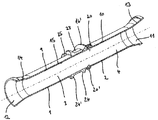
図1は、空洞3を形成する管状の本体2用の消音器1を示す。
FIG. 1 shows a
管状の本体2は、例えばプラスチック又は金属製のパイプとすることができる。管状の本体2は、弾性変形可能な材料から作製することができ、例えばホースとして設計することができる。管状の本体2は、冷却剤が管状の本体の内部で循環する冷却系の冷却剤回路の部分である。図示される消音器1は、冷却剤がガス状形態で存在する冷却剤回路の上記の部分に特に適している。このようにして、消音器1は、コンプレッサ(図示せず)によって生じる騒音を効果的に低減することができる。消音器1は、別個に製造され、かつ組み付け中に管状の本体2の空洞3内へ挿入されるインサート26として設計される。
The
消音器1は中央流路4を有する。流路4は管状の本体2と同軸に位置付けられる。さらに、4つの共鳴器チャンバ5、6、7、8が軸方向に互いに隣接して設けられる。流路4と共鳴器チャンバ5、6、7、8とは隔壁9によって分離され、当該隔壁9は、その内側に流路4を形成し、流路4をそれぞれの外側共鳴器チャンバ5、6、7及び8から分離する。隔壁9は、インサートとして設計される消音器1の部分によって形成される。共鳴器チャンバ5、6、7、8はここでは、内側パイプ10の周りにリング状に延びる。
The
さらに、図1において内側パイプの内側断面積は消音器1の軸方向に変化することが明らかである。内側パイプ10の内側断面積は、消音器1の入口11における入口断面積から始まり、中央エリア15の中間断面積に達するまで狭まる。そこから、内側断面積は、消音器1の出口12における出口断面積に至るまで再び広がる。入口11における入口断面積及び出口12における出口断面積は、管状の本体2の内側断面積にほぼ相当する。このようにして、流れは、妨げられず、流動損失が僅かしかない状態で管状の本体2を通って消音器1の流路4に達することができ、そこから出て再び管状の本体2に入ることができる。
Furthermore, in FIG. 1, it is clear that the inner cross-sectional area of the inner pipe changes in the axial direction of the
図示の実施形態では、内側パイプ10は、入口11と出口12とを最も狭い断面を有するエリア15で接続する2つの円錐形部分13、14を有する。図示の実施形態では、円錐形部分13及び14は、同じ軸方向長さを有する。最も狭い断面を有するエリア15は円筒形断面を有する。
In the illustrated embodiment, the
各共鳴器チャンバ5、6、7、8は、内側パイプ10によって内側が区切られ、管状の本体2の部分によって外側が区切られている。加えて、消音器1は、複数の共鳴器チャンバ5、6、7、8が内側パイプ10と管状の本体2との間に形成される空間において分離されるようにウェブ16、17、18を有する。これらのウェブ16、17、18の各々は、内側パイプ10上に位置付けられており、環状の円周方向設計を有する。管状の本体2がウェブ16、17、18のエリアにおいて消音器1と密接するように、ウェブ16、17、18の外径は管状の本体2の内径と一致している。円周方向ウェブ16、17、18は、半径方向外側を向いている。ウェブ16は、軸方向に隣接した共鳴器チャンバ5、6を分離する。対応して、ウェブ17は共鳴器チャンバ6、7を分離し、ウェブ18は共鳴器チャンバ7、8を分離する。共鳴器チャンバ5及び8は、管状の本体2と接触している内側パイプ10の部分によってそれらチャンバの外側端部で区切られる。共鳴器チャンバ5、6、7、8は、それらの軸方向長さにわたって一定の外径を有するが、内径が変化する。
Each
共鳴器チャンバ5、6、7、8は、ヘルムホルツ共鳴器の原理に従って、騒音の低減を可能にする。このために、それぞれが或る容積を有する共鳴器チャンバ5、6、7、8は、接続チャネル19及び19’、20及び20’、21及び21’並びに22及び22’を介して流路4に接続されている。図示の実施形態では、各共鳴器チャンバ5、6、7、8は、2つの対向した接続チャネル19及び19’、20及び20’、21及び21’並びに22及び22’を介して流路4に接続されている。各接続チャネルは小さい円形の開口部を囲む。接続チャネル19、19’、20、20’、21、21’、22及び22’は、共鳴器チャンバ5、6、7、8ごとに異なる長さを有し、これによって意図した周波数帯域への波長調整が可能となる。図示の実施形態では、2つの対向した接続チャネル19、19’は、肉厚の大きさ程度の長さを有する。2つの接続チャネル21、21’は、僅かにより長い。接続チャネル22、22’及び20、20’は際立ってより大きな長さを有する。接続チャネル19、19’、20、20’、21、21’、22、22’は、隔壁9及び内側パイプ10のチャネル状の部分によって形成される。接続チャネル19、19’、20、20’、21、21’、22、22’は、インサートの円周上の意図された位置に配置することもできる。
The
図示の消音器1は、射出成形部品としてプラスチックから作製することができる。弾塑性材料が特に適している。この場合、消音器1は、湾曲した管状の本体に難なく挿入可能でもある。さらに、この場合消音器は、例えば管状の本体の湾曲部のエリアで生じる可能性がある、管状の本体の平坦化又は楕円化に難なく適合することができる。
The illustrated
図2a及び図2bは、管状の本体への挿入前の、図1からの消音器1を示す。内側パイプ10上に位置付けられているウェブ16、17、18及び円錐形部分13、14及び内側パイプ10の最も狭い断面を有するエリア15が、はっきりと認識できる。さらに、接続チャネル19、19’、20、20’、21、21’、22、22’がはっきりと認識できる。
2a and 2b show the
図3a及び図3bは、湾曲部を有する管状の本体2に挿入された消音器1を示す。例えば、管状の本体は、湾曲部を有して設置されるホースとして設計されることもできる。消音器1は弾塑性材料から作製されるため、図2aに示される直線状の形状で製造された場合でも管状の本体2の湾曲部に適合することができる。湾曲した管状の本体においても同様に、ウェブ16、17、18が、管状の本体が曲がらないようにする必要なく、消音器1と管状の本体の内側との良好な接触をもたらす。
3a and 3b show a
図4a及び図4bは、管状の本体への挿入前の、本発明による消音器の別の実施形態を示す。同じ機能を有する部分には前述の図と同じ参照符号が付されている。図4a及び図4bにも適用されるそれぞれの記述を参照する。 Figures 4a and 4b show another embodiment of a silencer according to the present invention prior to insertion into a tubular body. Portions having the same function are denoted by the same reference numerals as those in the above-described drawings. Reference is made to the respective descriptions that also apply to FIGS. 4a and 4b.
図4a及び図4bに示される実施形態では、円周方向ウェブ36によって分離される2つの共鳴器チャンバのみ形成される。ウェブ16’は、上述の実施形態におけるウェブ16、17及び18のように、環状の円周方向設計を有する。加えて、ウェブ16’は、内側パイプ10の外側に突出した状態で位置付けられる。共鳴器チャンバの各々は、2つの接続チャネル20、20’及び22、22’を介して流路4に接続される。図4a及び図4bに示される実施形態では、内側パイプは同様に円錐形部分13、14を有する。しかしながら、これらの部分は、図1に示される実施形態の場合よりも軸方向により短い。したがって、最も狭い断面を有するエリア15は、それに応じてより長い。このようにして、より大きな容積が共鳴器チャンバに利用可能である。
In the embodiment shown in FIGS. 4 a and 4 b, only two resonator chambers separated by the circumferential web 36 are formed. The web 16 'has an annular circumferential design, like the
消音器1を固定するために、インサートは内側パイプ10の外側にクランプゾーン23を有する。ホースと同様に管状の本体が変形可能な材料から作製されている場合、消音器1を有する管状の本体は、クランプ装置、例えばホースクランプを用いてクランプゾーン23において締結することができる。図示の実施形態では、このために、内側パイプ10の肉厚がクランプゾーン23において補強されている。クランプゾーン23は、外側を向いているクランプ縁部24、24’によって両側を区切られる。このようにして、良好な軸方向固定が達成される。図示の実施形態では、クランプ縁部24は、ウェブ16’の斜側面によって形成される。クランプ縁部24から軸方向に離間しているクランプ縁部24’は、切断貫通部25を有する。このようにして、クランプ縁部24’の両側にある空間が、連続した共鳴器チャンバを形成することができる。
In order to secure the
1 消音器
2 管状の本体
3 空洞
4 流路
5 共鳴器チャンバ
6 共鳴器チャンバ
7 共鳴器チャンバ
8 共鳴器チャンバ
9 隔壁
10 内側パイプ
11 入口
12 出口
13 円錐形部分
14 円錐形部分
15 最も狭い断面を有するエリア
16、16’ ウェブ
17 ウェブ
18 ウェブ
19、19’ 接続チャネル
20、20’ 接続チャネル
21、21’ 接続チャネル
22、22’ 接続チャネル
23 クランプゾーン
24、24’ クランプ縁部
25 切断貫通部
26 インサート
DESCRIPTION OF
Claims (10)
Applications Claiming Priority (2)
| Application Number | Priority Date | Filing Date | Title |
|---|---|---|---|
| EP09013111.1 | 2009-10-16 | ||
| EP09013111.1A EP2357330B1 (en) | 2009-10-16 | 2009-10-16 | Cooling circuit with acoustic baffler for a tubular body forming a cavity |
Related Parent Applications (1)
| Application Number | Title | Priority Date | Filing Date |
|---|---|---|---|
| JP2012533509A Division JP5785173B2 (en) | 2009-10-16 | 2010-10-04 | A silencer for the main body that forms a tubular cavity |
Publications (2)
| Publication Number | Publication Date |
|---|---|
| JP2014231840A JP2014231840A (en) | 2014-12-11 |
| JP5918314B2 true JP5918314B2 (en) | 2016-05-18 |
Family
ID=41404203
Family Applications (2)
| Application Number | Title | Priority Date | Filing Date |
|---|---|---|---|
| JP2012533509A Expired - Fee Related JP5785173B2 (en) | 2009-10-16 | 2010-10-04 | A silencer for the main body that forms a tubular cavity |
| JP2014144766A Expired - Fee Related JP5918314B2 (en) | 2009-10-16 | 2014-07-15 | A silencer for the main body that forms a tubular cavity |
Family Applications Before (1)
| Application Number | Title | Priority Date | Filing Date |
|---|---|---|---|
| JP2012533509A Expired - Fee Related JP5785173B2 (en) | 2009-10-16 | 2010-10-04 | A silencer for the main body that forms a tubular cavity |
Country Status (8)
| Country | Link |
|---|---|
| US (1) | US8087493B2 (en) |
| EP (1) | EP2357330B1 (en) |
| JP (2) | JP5785173B2 (en) |
| KR (2) | KR20120095915A (en) |
| CN (2) | CN102575538A (en) |
| BR (1) | BR112012008931A2 (en) |
| ES (1) | ES2549177T3 (en) |
| WO (1) | WO2011044993A1 (en) |
Families Citing this family (34)
| Publication number | Priority date | Publication date | Assignee | Title |
|---|---|---|---|---|
| US8596398B2 (en) | 2007-05-16 | 2013-12-03 | Polaris Industries Inc. | All terrain vehicle |
| US8994494B2 (en) | 2008-10-10 | 2015-03-31 | Polaris Industries Inc. | Vehicle security system |
| US10358187B2 (en) | 2014-01-10 | 2019-07-23 | Polaris Industries Inc. | Snowmobile |
| US9488079B2 (en) | 2012-02-07 | 2016-11-08 | Black Widow Performance, Inc. | Muffler for automobile |
| WO2013119958A2 (en) | 2012-02-09 | 2013-08-15 | Polaris Industries Inc. | Snowmobile |
| CN103711984B (en) * | 2012-09-28 | 2018-04-13 | 费希尔控制国际公司 | Simplified modal attenuator |
| WO2014093215A1 (en) * | 2012-12-10 | 2014-06-19 | Eaton Corporation | Resonator with liner |
| WO2014184377A2 (en) * | 2013-05-17 | 2014-11-20 | Resmed Paris Sas | Flow diffuser and sound cone |
| CN104500178B (en) * | 2013-11-27 | 2016-11-09 | 广东西电动力科技股份有限公司 | A kind of complex muffler preventing and treating diesel generating set low-frequency noise |
| US9845004B2 (en) * | 2014-01-10 | 2017-12-19 | Polaris Industries Inc. | Snowmobile |
| JP6616322B2 (en) * | 2014-04-09 | 2019-12-04 | ティコナ・エルエルシー | The camera module |
| DE102014115898B4 (en) | 2014-10-31 | 2019-07-25 | Dietrich Denker | resonator |
| KR101683491B1 (en) | 2014-12-09 | 2016-12-07 | 현대자동차 주식회사 | Heat exchanger for vehicle |
| RU2590216C1 (en) * | 2015-03-18 | 2016-07-10 | федеральное государственное бюджетное образовательное учреждение высшего образования "Пермский национальный исследовательский политехнический университет" | Resonance cell for suppression of acoustic waves |
| US9982639B2 (en) | 2015-08-11 | 2018-05-29 | Rl Hudson & Company | Tunable injection molded resonator |
| JP6587521B2 (en) * | 2015-11-19 | 2019-10-09 | 小島プレス工業株式会社 | Vehicle silencer |
| CN105946502B (en) * | 2016-05-03 | 2019-01-29 | 北京新能源汽车股份有限公司 | Silencing pipe assembly for air conditioner and electric automobile with same |
| GB2551578B (en) * | 2016-06-24 | 2019-12-11 | Jaguar Land Rover Ltd | Conduit for reducing noise |
| KR102440596B1 (en) | 2017-11-28 | 2022-09-05 | 현대자동차 주식회사 | Heat exchanger for vehicle |
| DE102017130661A1 (en) * | 2017-12-20 | 2019-06-27 | Montaplast Gmbh | Broadband damper for a motor vehicle engine |
| US10793181B2 (en) | 2018-02-13 | 2020-10-06 | Polaris Industries Inc. | All-terrain vehicle |
| CN108561669B (en) * | 2018-03-09 | 2020-05-12 | 中国人民解放军海军工程大学 | Elastic back cavity type pipeline vibration damping and noise eliminating device |
| CN108425719A (en) * | 2018-05-17 | 2018-08-21 | 潍柴动力股份有限公司 | Muffler and automobile |
| CN108974305B (en) * | 2018-06-27 | 2020-06-30 | 中国船舶重工集团公司第七一九研究所 | Resonance silencing inter-board flow channel |
| US11815198B2 (en) | 2018-11-27 | 2023-11-14 | Smith & Burgess Process Safety Consulting | Resonator for a pressurized fluid system |
| WO2020154295A1 (en) | 2019-01-21 | 2020-07-30 | Toledo Molding & Die, Inc. | Inline high frequency fiber silencer |
| JP6871285B2 (en) * | 2019-02-04 | 2021-05-12 | フタバ産業株式会社 | Tail pipe |
| CN109854854B (en) * | 2019-03-27 | 2024-03-08 | 麦映辉 | Gas flow pipeline and gas treatment equipment |
| US10823036B1 (en) * | 2019-06-25 | 2020-11-03 | Faurecia Emissions Control Technologies, Usa, Llc | Method and apparatus to accommodate sensors on an exhaust component |
| KR102233359B1 (en) * | 2019-08-27 | 2021-03-30 | 주식회사 화승알앤에이 | System for refrigerants pipe |
| DE102019123902A1 (en) * | 2019-09-05 | 2021-03-11 | Hanon Systems | Device for damping pressure pulsations for a compressor of a gaseous fluid |
| US11698008B2 (en) * | 2020-02-14 | 2023-07-11 | Tenneco Automotive Operating Company Inc. | Exhaust device |
| CN111609243B (en) * | 2020-05-26 | 2022-04-05 | 北京绿创声学工程股份有限公司 | Manufacturing method of large equivalent diameter conical tandem type noise elimination channel |
| US11965442B2 (en) | 2022-06-01 | 2024-04-23 | Toyota Motor Engineering & Manufacturing North America, Inc. | Sound mitigation for a duct |
Family Cites Families (22)
| Publication number | Priority date | Publication date | Assignee | Title |
|---|---|---|---|---|
| US2051515A (en) * | 1935-10-07 | 1936-08-18 | Maxim Silencer Co | Sound attenuating device |
| US2127672A (en) * | 1935-10-25 | 1938-08-23 | Maxim Silencer Co | Sound attenuating device |
| US2271892A (en) * | 1936-07-15 | 1942-02-03 | Maxim Silencer Co | Sound attenuating device |
| US2311676A (en) * | 1941-07-02 | 1943-02-23 | Maxim Silencer Co | Silencer |
| US3043499A (en) * | 1958-01-22 | 1962-07-10 | Basf Ag | Process and apparatus for circulating hot gases, especially under high pressures |
| DE1199514B (en) * | 1962-05-12 | 1965-08-26 | Guenther Gerber | Silencer |
| JPS6073010A (en) * | 1983-09-29 | 1985-04-25 | Sanshin Ind Co Ltd | Exhaust gas noise suppressor for ship propulsion machine |
| SU1453057A1 (en) * | 1987-04-27 | 1989-01-23 | Войсковая часть 27177 | Exhaust silencer |
| US5317112A (en) * | 1991-10-16 | 1994-05-31 | Hyundai Motor Company | Intake silencer of the variable type for use in motor vehicle |
| US5205719A (en) * | 1992-01-13 | 1993-04-27 | Copeland Corporation | Refrigerant compressor discharge muffler |
| DE4327562A1 (en) | 1993-08-17 | 1995-02-23 | Erwin Dipl Ing Koetter | Coaxial resonator silencer for high alternating pressures |
| US6116375A (en) | 1995-11-16 | 2000-09-12 | Lorch; Frederick A. | Acoustic resonator |
| JP3213567B2 (en) * | 1997-06-16 | 2001-10-02 | 株式会社オーツカ | Silencer for air conditioner |
| US6265081B1 (en) * | 1998-06-08 | 2001-07-24 | Mitsubishi Engineering Plastics Corporation | Integrally molded articles of polyamide resins |
| DE10102040A1 (en) | 2001-01-18 | 2002-07-25 | Mahle Filtersysteme Gmbh | Silencer, for a motor exhaust or turbo charger air intake, has a hollow body at the component to be suppressed containing a number of parallel Helmholtz resonators |
| US6684842B1 (en) * | 2002-07-12 | 2004-02-03 | Visteon Global Technologies, Inc. | Multi-chamber resonator |
| US7114525B2 (en) * | 2003-08-29 | 2006-10-03 | Dana Corporation | Method and apparatus for reduction of fluid-borne noise in hydraulic systems |
| DE102004029221A1 (en) * | 2004-06-16 | 2006-01-12 | Geiger Technik Gmbh | Acoustic damping device and device for conducting a fluid |
| JP2008031918A (en) * | 2006-07-28 | 2008-02-14 | Denso Corp | Intake device |
| FR2929172A1 (en) * | 2008-03-31 | 2009-10-02 | Hutchinson Sa | NOISE REDUCING DEVICE FOR THE AIR CONDITIONING CIRCUIT OF A MOTOR VEHICLE, DRIVING AND CIRCUIT INCORPORATING IT |
| US7934581B2 (en) * | 2009-01-30 | 2011-05-03 | Eaton Corporation | Broadband noise resonator |
| US8327975B2 (en) * | 2009-09-30 | 2012-12-11 | Ford Global Technologies, Llc | Acoustic silencer |
-
2009
- 2009-10-16 ES ES09013111.1T patent/ES2549177T3/en active Active
- 2009-10-16 EP EP09013111.1A patent/EP2357330B1/en not_active Not-in-force
-
2010
- 2010-10-04 WO PCT/EP2010/006034 patent/WO2011044993A1/en active Application Filing
- 2010-10-04 KR KR1020127012489A patent/KR20120095915A/en active Application Filing
- 2010-10-04 JP JP2012533509A patent/JP5785173B2/en not_active Expired - Fee Related
- 2010-10-04 CN CN2010800466069A patent/CN102575538A/en active Pending
- 2010-10-04 BR BR112012008931-5A patent/BR112012008931A2/en not_active Application Discontinuation
- 2010-10-04 KR KR1020157019111A patent/KR20150088329A/en not_active Application Discontinuation
- 2010-10-04 CN CN201510315903.3A patent/CN104879601A/en active Pending
- 2010-10-13 US US12/903,793 patent/US8087493B2/en not_active Expired - Fee Related
-
2014
- 2014-07-15 JP JP2014144766A patent/JP5918314B2/en not_active Expired - Fee Related
Also Published As
| Publication number | Publication date |
|---|---|
| WO2011044993A1 (en) | 2011-04-21 |
| CN102575538A (en) | 2012-07-11 |
| BR112012008931A2 (en) | 2020-09-24 |
| US8087493B2 (en) | 2012-01-03 |
| US20110088968A1 (en) | 2011-04-21 |
| ES2549177T3 (en) | 2015-10-23 |
| KR20120095915A (en) | 2012-08-29 |
| EP2357330B1 (en) | 2015-08-19 |
| CN104879601A (en) | 2015-09-02 |
| KR20150088329A (en) | 2015-07-31 |
| EP2357330A1 (en) | 2011-08-17 |
| JP2013507592A (en) | 2013-03-04 |
| JP2014231840A (en) | 2014-12-11 |
| JP5785173B2 (en) | 2015-09-24 |
Similar Documents
| Publication | Publication Date | Title |
|---|---|---|
| JP5918314B2 (en) | A silencer for the main body that forms a tubular cavity | |
| US10907517B2 (en) | Silencer and vehicle engine including same | |
| US7810609B2 (en) | Muffler | |
| US20170356585A1 (en) | Damping device | |
| GB2389150A (en) | Noise suppressor eg for vehicular turbocharger duct | |
| US9593607B2 (en) | Muffler for an exhaust system of an internal combustion engine | |
| JP2020073801A (en) | Noise eliminator | |
| US11199116B2 (en) | Acoustically tuned muffler | |
| US20070295554A1 (en) | Sound Proofing Device and Device for Conducting a Fluid | |
| KR101901208B1 (en) | Compressor of an exhaust-gas turbocharger | |
| KR20140074225A (en) | Universal attenuation device for air-conditioning circuit | |
| WO2014141778A1 (en) | Exhaust pipe | |
| JPH09112780A (en) | Silencer | |
| CN113396073A (en) | Air duct for a motor vehicle and method for producing the same | |
| US20180347441A1 (en) | Exhaust gas outlet system for a motor vehicle, motor vehicle having such an exhaust gas outlet system, and method for producing an exhaust gas outlet system | |
| RU2654775C2 (en) | Silencer | |
| WO2014102747A1 (en) | A broadband silencer | |
| JP2019132266A (en) | Muffler | |
| JP4380879B2 (en) | Intake silencer for internal combustion engine | |
| US10161275B2 (en) | Compact muffler having multiple reactive cavities providing multi-spectrum attenuation for enhanced noise suppression | |
| US20220260045A1 (en) | Resonator insert for insertion into an intake pipe of a turbocharger, turbocharger and resonator | |
| JP2022181109A (en) | Interference length variable silencer | |
| RU2633274C2 (en) | Silencer for a vehicle |
Legal Events
| Date | Code | Title | Description |
|---|---|---|---|
| A131 | Notification of reasons for refusal |
Free format text: JAPANESE INTERMEDIATE CODE: A131 Effective date: 20150625 |
|
| A977 | Report on retrieval |
Free format text: JAPANESE INTERMEDIATE CODE: A971007 Effective date: 20150630 |
|
| A521 | Request for written amendment filed |
Free format text: JAPANESE INTERMEDIATE CODE: A523 Effective date: 20150925 |
|
| TRDD | Decision of grant or rejection written | ||
| A01 | Written decision to grant a patent or to grant a registration (utility model) |
Free format text: JAPANESE INTERMEDIATE CODE: A01 Effective date: 20160310 |
|
| A61 | First payment of annual fees (during grant procedure) |
Free format text: JAPANESE INTERMEDIATE CODE: A61 Effective date: 20160407 |
|
| R150 | Certificate of patent or registration of utility model |
Ref document number: 5918314 Country of ref document: JP Free format text: JAPANESE INTERMEDIATE CODE: R150 |
|
| R250 | Receipt of annual fees |
Free format text: JAPANESE INTERMEDIATE CODE: R250 |
|
| R250 | Receipt of annual fees |
Free format text: JAPANESE INTERMEDIATE CODE: R250 |
|
| R250 | Receipt of annual fees |
Free format text: JAPANESE INTERMEDIATE CODE: R250 |
|
| R250 | Receipt of annual fees |
Free format text: JAPANESE INTERMEDIATE CODE: R250 |
|
| LAPS | Cancellation because of no payment of annual fees |