JP5917069B2 - COMMUNICATION CONTROL DEVICE AND ITS CONTROL METHOD - Google Patents
COMMUNICATION CONTROL DEVICE AND ITS CONTROL METHOD Download PDFInfo
- Publication number
- JP5917069B2 JP5917069B2 JP2011213383A JP2011213383A JP5917069B2 JP 5917069 B2 JP5917069 B2 JP 5917069B2 JP 2011213383 A JP2011213383 A JP 2011213383A JP 2011213383 A JP2011213383 A JP 2011213383A JP 5917069 B2 JP5917069 B2 JP 5917069B2
- Authority
- JP
- Japan
- Prior art keywords
- bus
- interface
- connection
- recording medium
- host
- Prior art date
- Legal status (The legal status is an assumption and is not a legal conclusion. Google has not performed a legal analysis and makes no representation as to the accuracy of the status listed.)
- Active
Links
Images


Classifications
-
- G—PHYSICS
- G06—COMPUTING; CALCULATING OR COUNTING
- G06F—ELECTRIC DIGITAL DATA PROCESSING
- G06F13/00—Interconnection of, or transfer of information or other signals between, memories, input/output devices or central processing units
- G06F13/38—Information transfer, e.g. on bus
- G06F13/382—Information transfer, e.g. on bus using universal interface adapter
- G06F13/385—Information transfer, e.g. on bus using universal interface adapter for adaptation of a particular data processing system to different peripheral devices
Description
本発明は、通信制御に関し、特に、独立した複数のデータバスを有するコネクタを介して周辺デバイスを接続する場合の通信制御技術に関するものである。 The present invention relates to communication control, and more particularly to a communication control technique when peripheral devices are connected via a connector having a plurality of independent data buses.
近年、次世代高速インタフェースとして最高5Gbpsのデータ転送を実現するUSB3.0(非特許文献1)が開発されている。USB3.0は、Super−Speed(SS)モード(5Gbps)モードを含む。そして、USB3.0は、既存のUSB2.0の3つの転送モードであるHigh−Speed(480Mbps)モード、Full−Speed(12Mbps)モード、Low−Speed(1.5Mbps)モードも併せてサポートしている。 In recent years, USB 3.0 (Non-Patent Document 1) has been developed as a next-generation high-speed interface that realizes data transfer of up to 5 Gbps. USB3.0 includes a Super-Speed (SS) mode (5 Gbps) mode. USB3.0 also supports three existing USB2.0 transfer modes: High-Speed (480 Mbps) mode, Full-Speed (12 Mbps) mode, and Low-Speed (1.5 Mbps) mode. Yes.
一般的にUSBのホスト装置のバスアーキテクチャは、1つのホストコントローラから複数のコネクタに分岐する構成をとっている。そして、複数のデバイスが接続されている場合は、ホストコントローラが5Gbpsの帯域を接続された複数のデバイスに割り振り帯域を共有することで、当該複数のデバイスそれぞれへのデータ転送を実現している。そのため、複数のデバイスが同時にデータ転送をしている場合、各デバイスに割り振られるデータ転送帯域は少なくなる。 In general, the bus architecture of a USB host device is configured to branch from one host controller to a plurality of connectors. When a plurality of devices are connected, the host controller allocates a bandwidth of 5 Gbps to a plurality of connected devices and shares the bandwidth, thereby realizing data transfer to each of the plurality of devices. Therefore, when a plurality of devices are simultaneously transferring data, the data transfer bandwidth allocated to each device is reduced.
一方、記録媒体のインタフェースの高速化も進んでいる。例えば、SDカード規格のSDXC(eXtended Capacity) は複数の転送モードを持ち、最高速の転送モードで2.4Gbpsのデータ転送を実現すると言われている。また、既存のSDHC(High Capacity)やSDとの下位互換もサポートしている。 On the other hand, the speed of the recording medium interface is also increasing. For example, SDXC (eXtended Capacity) of the SD card standard has a plurality of transfer modes and is said to realize data transfer of 2.4 Gbps in the fastest transfer mode. It also supports backward compatibility with existing SDHC (High Capacity) and SD.
この場合、図13に示すように、SDXCに対応したカードインタフェース2002およびUSB3.0に対応したSSコントローラ2004を備えるデバイス2000を想定することが出来る。ここで、SDHCカードを使用した場合、カードインタフェース2002の速度は、一般的にUSB2.0モードの最高速度である480Mbps未満であるため、USBホスト機器との接続にSSモードを用いる利点は少ない。むしろUSB2.0モードで接続して、高速転送が必要とされる他のデバイスのためにSSモードの帯域を開けておく方がシステムの運用上望ましい。そこで、例えば特許文献1では、周辺装置(デバイス)側に転送手段を切り替える機械的なスイッチを備え、運用方法に応じてユーザがスイッチにより使用するデータ転送手段を選択する技術が提案されている。
In this case, as shown in FIG. 13, a
しかしながら、上述の従来技術によれば、高速転送を必要とするかしないかをユーザが判断し、手動でデータ転送手段を切り替える必要がある。そのため、ユーザ操作が煩雑になるといった問題がある。 However, according to the above-described prior art, it is necessary for the user to determine whether or not high-speed transfer is necessary, and to manually switch the data transfer means. Therefore, there is a problem that the user operation becomes complicated.
本発明は上述の問題点に鑑みなされたものであり、独立した複数のデータバスを有するコネクタを介してホスト装置とデバイス装置とを接続する場合のデータ転送をより好適に実行可能とする通信制御技術に関するものである。 The present invention has been made in view of the above-described problems, and enables communication control to more suitably execute data transfer when a host apparatus and a device apparatus are connected via a connector having a plurality of independent data buses. It is about technology.
上述の1以上の問題点を解決するため、本発明の通信制御装置は以下の構成を備える。すなわち、通信制御装置において、第1のバスコントローラにより制御される第1バスと、第2のバスコントローラにより制御され前記第1バスより最大転送速度が小さい第2バスと、を含む複数のホストインタフェースと、着脱可能な記録媒体と接続するためのカードインタフェースと、第1バスと第2バスとを含むデバイスインタフェースと、を含む読取装置が前記複数のホストインタフェースの何れかに接続され、かつ、前記カードインタフェースに着脱可能な記録媒体が接続されている場合、前記着脱可能な記録媒体のデータ転送速度を決定する決定手段と、前記決定手段により決定されたデータ転送速度が所定の閾値を超える場合に前記接続されたホストインタフェースの第1バスと前記デバイスインタフェースの第1バスとを介して前記読取装置と接続を確立するように制御し、前記データ転送速度が前記所定の閾値以下の場合に前記接続されたホストインタフェースの第2バスと前記デバイスインタフェースの第2バスとを介して前記読取装置と接続を確立するように制御する制御手段と、を有し、前記ホストインタフェースの第1バスを介して前記読取装置との接続を確立している状態で、前記記録媒体のデータ転送速度が前記所定の閾値を超えないと判断された場合、前記制御手段は、前記読取装置との前記ホストインタフェースの第1バスを介した接続を一旦切断し、該切断が完了したことに応じて前記読取装置から送信される前記デバイスインタフェースの第1バスを介した接続の要求に対して応答しないことにより、前記デバイスインタフェースの第2バスを介して前記読取装置と再接続するよう制御する。 In order to solve one or more problems described above, the communication control device of the present invention has the following configuration. That is, in the communication control apparatus, a plurality of host interfaces including a first bus controlled by a first bus controller and a second bus controlled by a second bus controller and having a lower maximum transfer rate than the first bus. A reading device including a card interface for connecting to a removable recording medium, and a device interface including a first bus and a second bus, and connected to any of the plurality of host interfaces; and When a removable recording medium is connected to the card interface, a determining means for determining a data transfer speed of the removable recording medium, and a case where the data transfer speed determined by the determining means exceeds a predetermined threshold Via the first bus of the connected host interface and the first bus of the device interface To establish a connection with the reader, and when the data transfer rate is less than or equal to the predetermined threshold, the second bus of the connected host interface and the second bus of the device interface Control means for controlling to establish a connection with the reading device, and a data transfer rate of the recording medium in a state where the connection with the reading device is established via the first bus of the host interface. Is determined not to exceed the predetermined threshold, the control means disconnects the connection of the host interface with the reader via the first bus, and the disconnection is completed in response to the disconnection being completed. By not responding to the request for connection through the first bus of the device interface transmitted from the reader, the second bus of the device interface It controls to reconnect with the reading device via.
本発明によれば、独立した複数のデータバスを有するコネクタを介してホスト装置とデバイス装置とを接続する場合のデータ転送をより好適に実行可能とする通信制御技術を提供することができる。 According to the present invention, it is possible to provide a communication control technique that can more suitably execute data transfer when a host apparatus and a device apparatus are connected via a connector having a plurality of independent data buses.
以下に、図面を参照して、この発明の好適な実施の形態を詳しく説明する。なお、以下の実施の形態はあくまで例示であり、本発明の範囲を限定する趣旨のものではない。 Hereinafter, preferred embodiments of the present invention will be described in detail with reference to the drawings. The following embodiments are merely examples, and are not intended to limit the scope of the present invention.
(第1実施形態)
本発明に係る通信制御装置の第1実施形態として、ユニバーサル・シリアル・バス(USB)3.0仕様準拠のホストコントローラを有する通信制御装置400(以降、デバイス400と呼ぶ)を例に挙げて以下に説明する。なお、以下の説明では主に本発明に特有の部分について説明する。なお、USB3.0仕様に関する一般的な詳細動作については、USB3.0仕様書(非特許文献1)を参照することにより理解されるであろう。
(First embodiment)
As a first embodiment of a communication control apparatus according to the present invention, a communication control apparatus 400 (hereinafter referred to as a device 400) having a host controller compliant with the universal serial bus (USB) 3.0 specification will be described as an example. Explained. In the following description, parts specific to the present invention will be mainly described. Note that general detailed operations related to the USB 3.0 specification will be understood by referring to the USB 3.0 specification (Non-Patent Document 1).
<USB3.0のアーキテクチャ>
USB3.0のバスアーキテクチャについて説明する。図1はUSB3.0のバスアーキテクチャを説明する図である。
<USB 3.0 architecture>
The USB 3.0 bus architecture will be described. FIG. 1 is a diagram for explaining a USB 3.0 bus architecture.
ホスト装置100は、スーパースピード(SS:SuperSpeed)モード接続で使用されるホスト・コントローラ102(以下、SS102と呼ぶ)(第1のバスコントローラ)を備えている。また、非スーパースピード(NSS:Non-SuperSpeed)モード接続で使用されるホスト・コントローラ104(以下、NSS104と呼ぶ)(第2のバスコントローラ)を備えている。NSS104は、USB2.0仕様で規定されるHigh−Speed(HS)、Full−Speed(FS)、Low−Speed(LS)の各モードでのデータ転送を制御する。そして、SS102は、USB3.0仕様で新たに規定されたSuper−Speed(SS)モードでのデータ転送を制御する。なお、SS102およびNSS104の各コントローラ内には後述するリンク制御部が内蔵されている。また、バス106はSS専用バスであり、バス108はNSS専用バスである。なお、
デバイス装置120は、USB3.0ペリフェラルデバイスであり、SS(SuperSpeed)モード接続で使用されるデバイス・ファンクション・コントローラ122(以下、SSF122と呼ぶ)を備えている。また、NSS(Non-SuperSpeed)モード接続で使用されるデバイス・ファンクション・コントローラ124(以下、NSSF124と呼ぶ)を備えている。上述の各ホスト・コントローラと同様に、NSSF124は、USB2.0仕様で規定される各モードでのデータ転送を制御し、SSF122は、Super−Speed(SS)モードでのデータ転送を制御する。なお、SSF122およびNSSF124の各コントローラ内には後述するリンク制御部が内蔵されている。なお、ホスト・コントローラおよびデバイス・ファンクション・コントローラを総称してバスコントローラと呼ぶことにする。
The
The
ケーブル126はUSB3.0のケーブルであり、ケーブル126内には、SSモード用のデータ信号線とNSSモード用のデータ信号線が独立して存在している。上述したように、ホスト装置100はSS用のバス106(第1バス)とNSS用のバス108(第2バス)を独立して持っている。そのため、例えば、ホスト装置100は、コネクタ#3に接続された周辺デバイスとバス106でデータ転送中に、接続コネクタの1つであるコネクタ#1に接続された他の周辺デバイスとバス108でデータ転送することが可能である。
The
また、SS102、NSS104の各コントローラはそれぞれ複数のコネクタに接続しており、各コントローラに対し複数の周辺デバイスを接続しデータ転送を行うことも可能である。ただし、その場合、接続されたホスト・コントローラがもつ最大データ転送帯域(SS:5Gbps、NSS:480Mbps)を当該ホスト・コントローラに接続した複数の周辺デバイスで共有することになる。 Each controller of SS102 and NSS104 is connected to a plurality of connectors, respectively, and a plurality of peripheral devices can be connected to each controller to perform data transfer. In this case, however, the maximum data transfer bandwidth (SS: 5 Gbps, NSS: 480 Mbps) of the connected host controller is shared by a plurality of peripheral devices connected to the host controller.
図2はUSB3.0のケーブルにおける信号線を示す図である。200はUSB3.0ホスト側コネクタを示し、ホスト装置100のコネクタ#1〜#3のいずれかを示す。202はUSB3.0ペリフェラルデバイス側コネクタを示し、デバイス装置120のコネクタを示す。
FIG. 2 is a diagram showing signal lines in a USB 3.0 cable.
信号線ペア206(D+、D−)はNSS(USB2.0)モード接続で使用する信号線ペアである。つまり、NSSモードでは、信号線ペア206を使い半二重通信が行われる。一方、信号線ペア208(SSTX+、SSTX−)はSSモード接続においてホスト装置からデバイス装置の転送に使用する信号線ペアである。また、信号線ペア210(SSRX+、SSRX−)はSSモード接続においてデバイス装置からホスト装置の転送に使用する信号線ペアである。つまり、SSモードでは、信号線ペア208および信号線ペア210を使い全二重通信が行われる。また、信号線204(VBUS)、信号線212(GND)はNSSモード接続、SSモード接続の双方で使用される信号線である。
The signal line pair 206 (D +, D-) is a signal line pair used in NSS (USB 2.0) mode connection. That is, in the NSS mode, half-duplex communication is performed using the
図3はUSB3.0におけるペリフェラルデバイスの状態遷移図である。つまり、デバイス装置120が有する状態(ステート)および各状態間の遷移を示している。
FIG. 3 is a state transition diagram of a peripheral device in USB 3.0. That is, the state (state) which the
状態300は、信号線204(VBUS)の信号が無い状態、すなわちデバイス装置120がホスト装置100と物理的に接続されていない状態を示している。
A
状態302は、デバイス装置120のSS信号線がRx.DetectまたはPollingの状態であることを示す。ここで、Rx.Detectとは、USB3.0ホスト側のSSリンクと物理的(電気的)に接続されているかを検出する状態である。Pollingとはリンクトレーニングを行っている状態を示す。具体的には、ホスト装置100とデバイス装置120のリンク間でハンドシェイクを行い、通信可能か否かを検出する状態である。
In the
状態304は、ホスト装置100とデバイス装置120との間でSS接続が確立された状態を示す。状態306は、ホスト装置100とデバイス装置120との間でNSS(USB2.0)モード接続が確立され、SSリンクがRx.DetectまたはPollingの状態であることを示す。状態308は、ホスト装置100とデバイス装置120との間でNSS(USB2.0)モード接続が確立され、SSリンクが無効になっている状態を示す。
A
次に状態遷移の条件について説明する。遷移310は、VBUSが有効になった場合、すなわち、USBケーブルによりホスト装置100とデバイス装置120とが接続された場合の遷移を示す。遷移312は、SSのリンクがPollingからU0へ遷移した場合、すなわち、SSリンクでハンドシェイクをし、リンクがアクティブになった場合の遷移を示す。
Next, state transition conditions will be described. A
遷移314、遷移316、遷移318はそれぞれ、Rx.Detectまたはリンクトレーニングがタイムアウトになった場合の遷移を示す。遷移320は、NSS(USB2.0)リセット信号を受信した場合の遷移を示す。遷移322はSSリンクがPollingからU0へ変化した場合、すなわち、SSリンクでハンドシェイクをし、リンクがアクティブになった場合の遷移を示す。
図3から理解されるように、一般的には、USB3.0に対応したホスト装置のコネクタに、USB3.0に対応したデバイス装置を接続した場合、SSバス106を介した接続(SSモード接続)が行われる。そして、USB3.0ホスト装置のコネクタに、USB2.0(あるいはUSB1.1)デバイス装置が接続された場合、NSSバス108を介した接続(NSSモード接続)が行われる。 As understood from FIG. 3, generally, when a device device compatible with USB 3.0 is connected to a connector of a host device compatible with USB 3.0, connection via the SS bus 106 (SS mode connection) ) Is performed. When a USB 2.0 (or USB 1.1) device device is connected to the connector of the USB 3.0 host device, connection via the NSS bus 108 (NSS mode connection) is performed.
<装置構成>
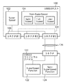
図4は、第1実施形態に係るデバイス400のブロック図である。デバイス400は、SSモード接続で使用されるコントローラ402(以下、SS402と呼ぶ)、NSSモード接続で使用されるコントローラ404(以下、NSS404と呼ぶ)に接続されたコネクタ424(第2インタフェース)を備える。コントローラはそれぞれデータバス408に接続されている。なお、以下ではデバイス400は、コネクタ424を介して外部装置であるホスト426に接続されるものとする。
<Device configuration>
FIG. 4 is a block diagram of the
接続制御部416はSSモード、NSSモードの各モードでの接続を制御する。転送速度判定部418は、カードインタフェース420(第1インタフェース)を介して接続された記録媒体422のデータ転送速度を判定する。なお、記録媒体422は着脱可能記録媒体であり、以下の説明ではSD規格に準拠したカード(SDカード)であるものとする。この場合、デバイス400はいわゆるカードリーダ(読取装置)に相当するものである。
The
もちろん、本発明はSDカードに限定されるものではなく、様々な記録方式の記録媒体が使用可能であり、代表的には半導体メモリ(フラッシュメモリやRAMなど)およびハードディスクドライブがある。また、接続インタフェース規格として、他のメモリカード規格(CF規格など)を用いてもよい。更には、USBインタフェースであってもよい。なお、USBインタフェースである場合には、第1実施形態のデバイス400はUSBハブ(Hub)に相当するものであり、記録媒体は、一般的にはマスストレージクラスのペリフェラルデバイスとして認識される。
Of course, the present invention is not limited to the SD card, and recording media of various recording methods can be used. Typically, there are a semiconductor memory (flash memory, RAM, etc.) and a hard disk drive. Further, other memory card standards (such as the CF standard) may be used as the connection interface standard. Furthermore, a USB interface may be used. In the case of the USB interface, the
ROM414は、CPU410が実行する各種の制御プログラム及び各種パラメータを格納する。RAM412は、CPU410のプログラム領域及びワーク領域として使用される。CPU410は、制御プログラムを実行することにより、CPUバス406を介して以上の各部を制御し後述の処理を実行する。なお、通信制御装置400の制御は1つのハードウェアが行ってもよいし、複数のハードウェアが処理を分担することで、装置全体の制御を行ってもよい。撮像部440は、光学レンズ、CCDなどのセンサ、シャッタ、絞りなどを含む。撮像部440は被写体を撮像し、画像データに変換する。変換された画像データはRAM412、カードI/F部420を経由して記録媒体422に記録される。なお、撮像部440は、SS402及びNSS404の制御とは独立に撮像し、記録媒体422に画像データを記録することが可能である。つまり、撮像部440による撮像及び記録媒体422への画像データの記録は、コネクタ424にホスト(PC)426が接続されていない場合でも実行可能である。
The
<接続制御方法について>
まず、USB3.0の接続シーケンスについて説明する。図5は、SSモードで接続する際のシーケンスを説明する図である。
<About connection control method>
First, a USB 3.0 connection sequence will be described. FIG. 5 is a diagram illustrating a sequence when connecting in the SS mode.
ステップS500では、ホスト426は、デバイス400がコネクタを介して接続されると、VBUSをONにする。ステップS502では、デバイス400はVBUS ONを検出し、ステップS504では、デバイス400は自身のSSリンクがReadyになるまで待つ。
In step S500, the
ステップS506では、デバイス400は、自身のSSのリンクがReadyになると、その旨をホスト426に通知する。ステップS508では、ホスト426は、デバイス400からの通知を受けて、接続コネクタ内の端子を介してデバイス400とSSのリンクが電気的に接続したことを検出する。ステップS510では、ホスト426とデバイス400の双方で、SSリンク間でリンクの初期化処理を行い、ステップS512では、SSモード接続が確立する。
In step S506, the
以下では、記録媒体422とデバイス400との接続、ホスト426とデバイス400との接続の何れが時間的に先であるかに基づいた2つのユースケースに分けて、第1実施形態に係る接続制御について説明する。
In the following, the connection control according to the first embodiment is divided into two use cases based on which of the connection between the
<ケース1:記録媒体422とデバイス400とを接続した後、ホスト426とデバイス400とを接続する場合。>
図6は、ケース1における接続制御を示す動作フローチャートである。
<Case 1: A case where the
FIG. 6 is an operation flowchart showing connection control in Case 1.
ステップS600では、カードインタフェース420は、記録媒体422が接続されたか監視し、接続された場合はステップS602に進む。ステップS602では、転送速度判定部418は、カードインタフェース420を制御して、記録媒体422に対し属性情報取得コマンドを発行する。ステップS604では、転送速度判定部418は、記録媒体422が応答した属性情報を取得する。
In step S600, the
ステップS606では、転送速度判定部418は、ステップS604で取得した属性情報に含まれるクラス情報(転送速度情報を示す)に基づいて、記録媒体422の転送速度がUSB2.0の最大転送速度(480Mbps)を超えるか否かを判定する。YESの場合はS608に進み、ホスト426とデバイス400とが接続されたとき、図5で説明したシーケンスに従ってSSモードにより接続を行う。一方、NOの場合はS610に進み、ホスト426とデバイス400とが接続されたとき、図7を参照して後述するシーケンスに従ってNSS(USB2.0)モードにより接続を行う。
In step S606, the transfer
図7は、ケース1におけるNSS(USB2.0)モードで接続するシーケンスを示す図であり、図6のステップS610に相当する部分を詳細に記載したものである。 FIG. 7 is a diagram showing a sequence for connection in the NSS (USB 2.0) mode in case 1, and describes in detail the portion corresponding to step S610 in FIG.
ステップS700では、ホスト426は、デバイス400がコネクタを介して接続されると、VBUSをONにする。ステップS702では、デバイス400はVBUS ONを検出し、ステップS704では、デバイス400は自身のSSリンクがReadyになるまで待つ。
In step S700, the
ステップS706では、デバイス400は、SS402を制御して、SSモードの信号線であるSSTX208及びSSRX210をハイインピーダンス(Hi−Z)にする。この動作により、SSモードでの接続は自動的に失敗し、ホスト426は、デバイス400がSSモードに未対応のデバイスであると判断する(S708)。
In step S706, the
ステップS710では、デバイス400は、NSS404を制御して、USB2.0信号線のD+をプルアップ(電圧をHiレベル)する。ステップS712では、ホスト426は、D+のプルアップされたことにより、接続コネクタ内の端子を介してデバイス400との間でUSB2.0のリンクが電気的に接続したことを検出する。ステップS714では、ホスト426とデバイス400の双方で、NSSリンク間でリンクの初期化処理を行い、ステップS716では、NSSモード接続が確立する。
In step S710, the
<ケース2:ホスト426とデバイス400とを接続した後、記録媒体422とデバイス400とを接続する場合。>
図8は、ケース2における接続制御を示す動作フローチャートである。
<Case 2: After connecting the
FIG. 8 is an operation flowchart showing connection control in Case 2.
ステップS800では、ホスト426とデバイス400とが接続されたとき、図5で説明したシーケンスに従ってSSモードにより接続を行う。ステップS802では、カードインタフェース420は、記録媒体422が接続されたか監視し、接続された場合はステップS804に進む。ステップS804では、転送速度判定部418は、カードインタフェース420を制御して、記録媒体422に対し属性情報取得コマンドを発行する。ステップS806では、転送速度判定部418は、記録媒体422が応答した属性情報を取得する。
In step S800, when the
ステップS808では、転送速度判定部418は、ステップS806で取得した属性情報に含まれるクラス情報に基づいて、記録媒体422の転送速度がUSB2.0の最大転送速度(480Mbps)を超えるか否かを判定する。YESの場合はS810に進み、ホスト426とデバイス400とが接続されたときも継続してSSモードにより接続を行う。一方、NOの場合はS812に進み、ホスト426とデバイス400とが接続されたとき、図9を参照して後述するシーケンスに従ってNSS(USB2.0)モードにより再接続を行う。
In step S808, the transfer
図9は、ケース2におけるNSS(USB2.0)モードで接続するシーケンスを示す図であり、図8のステップS812に相当する部分を詳細に記載したものである。 FIG. 9 is a diagram showing a sequence for connection in the NSS (USB 2.0) mode in case 2, and describes in detail the portion corresponding to step S812 in FIG.
ステップS900では、デバイス400は、SS402を制御して、SSモードの信号線であるSSTX208及びSSRX210をハイインピーダンス(Hi−Z)にする。この動作により、SSモードでの接続は失敗する。つまり、ステップS800で確立されたSSモードでの接続は切断され、ホスト426は、デバイス400はSSモードには未対応であると判断する(S902)。
In step S900, the
ステップS904では、デバイス400は、NSS404を制御して、USB2.0信号線のD+をプルアップ(電圧をHiレベル)する。ステップS906では、ホスト426は、D+のプルアップされたことにより、接続コネクタ内の端子を介してデバイス400との間でUSB2.0のリンクが電気的に接続したことを検出する。ステップS908では、ホスト426とデバイス400の双方で、NSSリンク間でリンクの初期化処理を行い、ステップS910では、NSSモード接続が確立する。
In step S904, the
以上ケース1および2について説明したように、第1実施形態によれば、デバイス400に接続された記録媒体422のデータ転送速度が所定の閾値以下の場合、NSS(USB2.0)モードで接続するよう制御する。これにより、必要なデータ転送速度が所定の閾値(480Mbps)を超える他のデバイスが接続された場合、当該他のデバイスはSSモード接続の帯域を占有することが出来る。
As described above with respect to cases 1 and 2, according to the first embodiment, when the data transfer speed of the
(第2実施形態)
第2実施形態では、ホストが、当該ホストとデバイスとの間のUSB接続モードを決定する形態について説明する。
(Second Embodiment)
In the second embodiment, a mode in which the host determines the USB connection mode between the host and the device will be described.
<装置構成>
図10は、第2実施形態に係る通信制御装置1000(以降、ホスト1000と呼ぶ)のブロック図である。ホスト1000は、SSモード接続で使用されるコントローラ1002(以下、SS1002と呼ぶ)、NSSモード接続で使用されるホスト・コントローラ1004(以下、NSS1004と呼ぶ)を備えている。また、コネクタ1026〜コネクタ1030を備える。コントローラはそれぞれSSモード専用データバス1010、NSS(USB2.0)モード専用データバス1008に接続されている。
<Device configuration>
FIG. 10 is a block diagram of a communication control apparatus 1000 (hereinafter referred to as a host 1000) according to the second embodiment. The
接続制御部1020はSSモード、NSSモードの各モードでの接続を制御する。転送速度算出部1018は、コネクタ1026〜コネクタ1030に接続されたデバイスと実際にデータ転送を行い、転送速度を算出する。
The
記録装置インタフェース1022は、例えばATAインタフェース等の外部記録装置と接続するためのインタフェースである。例えば、コネクタ1026を介してデバイス1032から読み出したデータをハードディスクドライブ(HDD)などの記録媒体1024へ記録するためのものである。
The
ROM1016は、CPU1012が実行する各種の制御プログラム及び各種パラメータを記憶する。RAM1014は、CPU1012のプログラム領域及びワーク領域として使用される。CPU1012は、制御プログラムを実行することにより、CPUバス1006を介して以上の各部を制御し後述の処理を実行する。なお、ホスト1000の制御は1つのハードウェアが行ってもよいし、複数のハードウェアが処理を分担することで、装置全体の制御を行ってもよい。撮像部1040は、光学レンズ、CCDなどのセンサ、シャッタ、絞りなどを含む。撮像部1040は被写体を撮像し、画像データに変換する。変換された画像データはRAM1014、記録装置I/F部1022を経由して記録媒体1024に記録される。なお、撮像部1040は、SS1002及びNSS1004の制御とは独立に撮像し、記録媒体1024に画像データを記録することが可能である。つまり、撮像部1040による撮像及び記録媒体1024への画像データの記録は、コネクタ1026にデバイス1032が接続されていない場合でも実行可能である。
The
<接続制御方法について>
図11は、第2実施形態における接続制御を示す動作フローチャートである。
<About connection control method>
FIG. 11 is an operation flowchart showing connection control in the second embodiment.
ステップS1100では、ホスト1000とデバイス1032とが接続されたとき、図5で説明したシーケンスに従ってSSモードにより接続を行う。ステップS1102では、ホスト1000は、デバイス1032に記録媒体が接続されたか確認し、接続されている場合はステップS1104に進む。ステップS1104では、ホスト1000は、デバイス1032に接続された記録媒体の転送速度を測定する。例えば、ホスト1000は、デバイス1032に装着された記録媒体の特定の領域に対し所定サイズのデータの書き込み及び読み出しを実行することにより転送速度を測定する。
In step S1100, when the
ステップS1106では、ホスト1000は、ステップS1104で測定した転送速度がUSB2.0の最大転送速度(480Mbps)を超えるか否かを判定する。YESの場合はS1108に進み、ホスト1000とデバイス1032とが接続されたときも継続してSSモードにより接続を行う。一方、NOの場合はS1110に進み、ホスト1000とデバイス1032とが接続されたとき、図12を参照して後述するシーケンスに従ってNSS(USB2.0)モードにより再接続を行う。
In step S1106, the
図12は、第2実施形態におけるNSS(USB2.0)モードで接続するシーケンスを示す図であり、図11のステップS1110に相当する部分を詳細に記載したものである。 FIG. 12 is a diagram showing a sequence for connection in the NSS (USB 2.0) mode in the second embodiment, and describes in detail the portion corresponding to step S1110 in FIG.
ステップS1200では、ホスト1000はVBUSを一旦OFFにする。この動作により、SSモードでの接続は失敗する。つまり、ステップS1100で確立されたSSモードでの接続は切断される(S1202)。ステップS1204では、ホスト1000はVBUSを再びONにする。ステップS1206では、デバイス1032はVBUS ONを検出し、ステップS1208では、デバイス1032は自身のSSリンクがReadyになるまで待つ。
In step S1200, the
ステップS1210では、デバイス1032は、自身のSSのリンクがReadyになると、その旨をホスト1000に通知する。ステップS1212では、ホスト1000は、デバイス1032との接続をNSS(USB2.0)モード接続にするために、デバイス1032のSSリンクとのハンドシェイク(接続要求)に応答しないようにSS1002を制御する。これにより、当該ハンドシェイクはタイムアウトすることになる。そのため、ステップS1214では、デバイス1032は、ホスト1000がSSに未対応であると判定し、NSS(USB2.0)モードで接続するために、D+をプルアップする。ステップS1216では、ホスト1000は、D+プルアップにより、NSS(USB2.0)が電気的に接続したことを検出する。ステップS1218では、ホスト1000とデバイス1032の双方で、NSSリンク間でリンクの初期化処理を行い、ステップS1220では、NSSモード接続が確立する。
In step S1210, when the link of its own SS becomes Ready, the
以上説明したように、第2実施形態によれば、ホスト1000に接続されたデバイス1032に接続された記録媒体のデータ転送速度が所定の閾値(480Mbps)以下の場合、NSS(USB2.0)モードで接続するよう制御する。これにより、必要なデータ転送速度が所定の閾値(480Mbps)を超える他のデバイスがホスト1000に接続された場合、当該他のデバイスはSSモード接続の帯域を占有することが出来る。
As described above, according to the second embodiment, when the data transfer speed of the recording medium connected to the
(その他の実施例)
また、本発明は、以下の処理を実行することによっても実現される。即ち、上述した実施形態の機能を実現するソフトウェア(プログラム)を、ネットワーク又は各種記憶媒体を介してシステム或いは装置に供給し、そのシステム或いは装置のコンピュータ(またはCPUやMPU等)がプログラムを読み出して実行する処理である。
(Other examples)
The present invention can also be realized by executing the following processing. That is, software (program) that realizes the functions of the above-described embodiments is supplied to a system or apparatus via a network or various storage media, and a computer (or CPU, MPU, or the like) of the system or apparatus reads the program. It is a process to be executed.
Claims (10)
着脱可能な記録媒体と接続するためのカードインタフェースと、第1バスと第2バスとを含むデバイスインタフェースと、を含む読取装置が前記複数のホストインタフェースの何れかに接続され、かつ、前記カードインタフェースに着脱可能な記録媒体が接続されている場合、前記着脱可能な記録媒体のデータ転送速度を決定する決定手段と、
前記決定手段により決定されたデータ転送速度が所定の閾値を超える場合に前記接続されたホストインタフェースの第1バスと前記デバイスインタフェースの第1バスとを介して前記読取装置と接続を確立するように制御し、前記データ転送速度が前記所定の閾値以下の場合に前記接続されたホストインタフェースの第2バスと前記デバイスインタフェースの第2バスとを介して前記読取装置と接続を確立するように制御する制御手段と、
を有し、
前記ホストインタフェースの第1バスを介して前記読取装置との接続を確立している状態で、前記記録媒体のデータ転送速度が前記所定の閾値を超えないと判断された場合、前記制御手段は、前記読取装置との前記ホストインタフェースの第1バスを介した接続を一旦切断し、該切断が完了したことに応じて前記読取装置から送信される前記デバイスインタフェースの第1バスを介した接続の要求に対して応答しないことにより、前記デバイスインタフェースの第2バスを介して前記読取装置と再接続するよう制御する
ことを特徴とする通信制御装置。 A plurality of host interfaces including: a first bus controlled by a first bus controller; and a second bus controlled by a second bus controller and having a maximum transfer speed smaller than that of the first bus;
A card interface for connection to a detachable recording medium, a first bus and a device interface and a second bus, reading includes apparatus is connected to one of said plurality of host interface, and wherein the card interface when the recording medium detachable to is connected, determining means for determining a data rate of said removable recording medium,
When the data transfer rate determined by the determining unit exceeds a predetermined threshold, a connection is established with the reader via the first bus of the connected host interface and the first bus of the device interface. Control to establish a connection with the reader via the second bus of the connected host interface and the second bus of the device interface when the data transfer rate is less than or equal to the predetermined threshold Control means;
Have
When it is determined that the data transfer rate of the recording medium does not exceed the predetermined threshold in a state where the connection with the reading device is established via the first bus of the host interface, A request for connection via the first bus of the device interface transmitted from the reading device in response to completion of the disconnection once the connection of the host interface with the reading device via the first bus is disconnected. The communication control apparatus is configured to control to reconnect to the reading apparatus via the second bus of the device interface by not responding to the apparatus.
ことを特徴とする請求項1に記載の通信制御装置。The communication control apparatus according to claim 1.
ことを特徴とする請求項1又は2に記載の通信制御装置。The communication control apparatus according to claim 1 or 2, characterized by the above.
ことを特徴とする請求項1乃至3の何れか1項に記載の通信制御装置。The communication control device according to any one of claims 1 to 3, wherein
ことを特徴とする請求項1乃至4の何れか1項に記載の通信制御装置。The communication control apparatus according to any one of claims 1 to 4, wherein the communication control apparatus includes:
ことを特徴とする請求項1乃至5の何れか1項に記載の通信制御装置。The communication control apparatus according to any one of claims 1 to 5, wherein
ことを特徴とする請求項1乃至5の何れか1項に記載の通信制御装置。The communication control apparatus according to any one of claims 1 to 5, wherein
前記第1のバスコントローラは、スーパースピード(SS)コントローラであり、 The first bus controller is a super speed (SS) controller;
前記第2のバスコントローラは、非スーパースピード(NSS)コントローラである The second bus controller is a non-super speed (NSS) controller
ことを特徴とする請求項1乃至7の何れか1項に記載の通信制御装置。The communication control apparatus according to any one of claims 1 to 7, wherein the communication control apparatus includes:
着脱可能な記録媒体と接続するためのカードインタフェースと、第1バスと第2バスとを含むデバイスインタフェースと、を含む読取装置が 前記複数のホストインタフェースの何れかに接続され、かつ、前記カードインタフェースに着脱可能な記録媒体が接続されている場合、前記着脱可能な記録媒体のデータ転送速度を決定する決定工程と、
前記決定工程により決定されたデータ転送速度が所定の閾値を超える場合に前記接続されたホストインタフェースの第1バスと前記デバイスインタフェースの第1バスとを介して前記読取装置と接続を確立するように制御し、前記データ転送速度が前記所定の閾値以下の場合に前記接続されたホストインタフェースの第2バスと前記デバイスインタフェースの第2バスとを介して前記読取装置と接続を確立するように制御する制御工程と、
を含み、
前記制御工程では、前記ホストインタフェースの第1バスを介して前記読取装置との接続を確立している状態で、前記記録媒体のデータ転送速度が前記所定の閾値を超えないと判断された場合、前記読取装置との前記ホストインタフェースの第1バスを介した接続を一旦切断し、該切断が完了したことに応じて前記読取装置から送信される前記デバイスインタフェースの第1バスを介した接続の要求に対して応答しないことにより、前記デバイスインタフェースの第2バスを介して前記読取装置と再接続するよう制御する
ことを特徴とする通信制御装置の制御方法。 Control of a communication control apparatus having a plurality of host interfaces including a first bus controlled by a first bus controller and a second bus controlled by a second bus controller and having a maximum transfer rate smaller than that of the first bus. A method,
A card interface for connection to a detachable recording medium, a first bus and a device interface and a second bus, reading includes apparatus is connected to one of said plurality of host interface, and wherein the card interface when the recording medium detachable to is connected, a determination step of determining a data transfer rate of the removable recording medium,
A connection is established with the reader via the first bus of the connected host interface and the first bus of the device interface when the data transfer rate determined by the determining step exceeds a predetermined threshold. Control to establish a connection with the reader via the second bus of the connected host interface and the second bus of the device interface when the data transfer rate is less than or equal to the predetermined threshold Control process;
Including
In the control step, when it is determined that the data transfer rate of the recording medium does not exceed the predetermined threshold in a state where the connection with the reading device is established via the first bus of the host interface, A request for connection via the first bus of the device interface transmitted from the reading device in response to completion of the disconnection once the connection of the host interface with the reading device via the first bus is disconnected. A control method for a communication control apparatus, wherein control is performed so as to reconnect to the reading apparatus via a second bus of the device interface by not responding to .
Priority Applications (2)
| Application Number | Priority Date | Filing Date | Title |
|---|---|---|---|
| JP2011213383A JP5917069B2 (en) | 2010-10-20 | 2011-09-28 | COMMUNICATION CONTROL DEVICE AND ITS CONTROL METHOD |
| US13/275,663 US9256561B2 (en) | 2010-10-20 | 2011-10-18 | Communication control apparatus and method of controlling the same |
Applications Claiming Priority (3)
| Application Number | Priority Date | Filing Date | Title |
|---|---|---|---|
| JP2010235876 | 2010-10-20 | ||
| JP2010235876 | 2010-10-20 | ||
| JP2011213383A JP5917069B2 (en) | 2010-10-20 | 2011-09-28 | COMMUNICATION CONTROL DEVICE AND ITS CONTROL METHOD |
Publications (3)
| Publication Number | Publication Date |
|---|---|
| JP2012108884A JP2012108884A (en) | 2012-06-07 |
| JP2012108884A5 JP2012108884A5 (en) | 2014-11-13 |
| JP5917069B2 true JP5917069B2 (en) | 2016-05-11 |
Family
ID=45973945
Family Applications (1)
| Application Number | Title | Priority Date | Filing Date |
|---|---|---|---|
| JP2011213383A Active JP5917069B2 (en) | 2010-10-20 | 2011-09-28 | COMMUNICATION CONTROL DEVICE AND ITS CONTROL METHOD |
Country Status (2)
| Country | Link |
|---|---|
| US (1) | US9256561B2 (en) |
| JP (1) | JP5917069B2 (en) |
Families Citing this family (15)
| Publication number | Priority date | Publication date | Assignee | Title |
|---|---|---|---|---|
| EP2800005A1 (en) * | 2009-05-20 | 2014-11-05 | Chronologic Pty Limited | Method and apparatus for synchronising the local time of a plurality of instruments |
| US8956346B2 (en) | 2010-05-14 | 2015-02-17 | Rainbow Medical, Ltd. | Reflectance-facilitated ultrasound treatment and monitoring |
| US8996747B2 (en) * | 2011-09-29 | 2015-03-31 | Cypress Semiconductor Corporation | Methods and physical computer-readable storage media for initiating re-enumeration of USB 3.0 compatible devices |
| US8843664B2 (en) | 2011-09-29 | 2014-09-23 | Cypress Semiconductor Corporation | Re-enumeration of USB 3.0 compatible devices |
| US11755510B2 (en) * | 2011-11-08 | 2023-09-12 | Seagate Technology Llc | Data detection and device optimization |
| US9707414B2 (en) * | 2012-02-14 | 2017-07-18 | Rainbow Medical Ltd. | Reflectance-facilitated ultrasound treatment and monitoring |
| US20130332764A1 (en) * | 2012-06-08 | 2013-12-12 | Apple Inc. | Intelligent inter-processor communication with power optimization |
| TWI464597B (en) * | 2012-07-19 | 2014-12-11 | Wistron Corp | Method of improving data transmission and related computer system |
| CN104823174B (en) * | 2012-09-30 | 2019-09-06 | 赛普拉斯半导体公司 | The method and system of USB3.0 compatible equipment enumerated again |
| WO2014121283A2 (en) * | 2013-02-04 | 2014-08-07 | Spectra7 Microsystems Ltd | Methods and systems for achieving higher video throughput and/or quality |
| US9575917B1 (en) * | 2013-08-30 | 2017-02-21 | Analogix Semiconductor, Inc. | Protocol for digital audio-video interface |
| JP6285750B2 (en) * | 2014-02-26 | 2018-02-28 | パナソニック株式会社 | Data transfer device, host device, data transfer system, and communication method setting method |
| KR102239572B1 (en) * | 2015-01-27 | 2021-04-13 | 삼성전자주식회사 | Method and apparatus for full duplex data transmission between electronic devices |
| CN109426644A (en) * | 2017-08-31 | 2019-03-05 | 西安中兴新软件有限责任公司 | A kind of rate adjusting method and device, equipment of USB data transmission |
| KR20220069380A (en) * | 2020-11-20 | 2022-05-27 | 삼성전자주식회사 | Method for receiving log information and electronic device therefor |
Family Cites Families (15)
| Publication number | Priority date | Publication date | Assignee | Title |
|---|---|---|---|---|
| JPH07320018A (en) * | 1994-05-26 | 1995-12-08 | Canon Inc | Memory card, electronic equipment using memory card, and method for setting access speed of memory card |
| US8078973B1 (en) * | 2002-06-25 | 2011-12-13 | Cypress Semiconductor Corporation | Visual indication of a device connection speed |
| JP2004328037A (en) * | 2003-04-21 | 2004-11-18 | Canon Inc | Imaging and image recording apparatus |
| JP2005327247A (en) | 2004-04-16 | 2005-11-24 | Sony Corp | Data storage device and voice reproduction system |
| US20050235091A1 (en) * | 2004-04-20 | 2005-10-20 | Caph Chen | USB hub with built-in storage device |
| JP4734898B2 (en) * | 2004-11-17 | 2011-07-27 | ソニー株式会社 | Information processing apparatus, information processing method, and program |
| JP2007122241A (en) * | 2005-10-26 | 2007-05-17 | Renesas Technology Corp | Memory card controller and memory card |
| US7246189B2 (en) * | 2005-11-18 | 2007-07-17 | Vetra Systems Corporation | Method and apparatus for enhancing universal serial bus |
| JP2008129836A (en) * | 2006-11-21 | 2008-06-05 | Renesas Technology Corp | Processing device |
| US8150452B2 (en) * | 2007-11-16 | 2012-04-03 | Standard Microsystems Corporation | Providing a connection between a memory medium of a mobile device and an external device |
| US7788428B2 (en) * | 2008-03-27 | 2010-08-31 | Sony Ericsson Mobile Communications Ab | Multiplex mobile high-definition link (MHL) and USB 3.0 |
| US20100262726A1 (en) * | 2009-01-13 | 2010-10-14 | Tauscher Brian E | Method and apparatus for implementing a limited functionality embedded universal serial (USB) host controller on a fully functional downstream USB port |
| US8112571B1 (en) * | 2009-07-23 | 2012-02-07 | Cypress Semiconductor Corporation | Signal connection device and method |
| US8135883B2 (en) * | 2010-01-19 | 2012-03-13 | Standard Microsystems Corporation | USB hub apparatus supporting multiple high speed devices and a single super speed device |
| US8504755B2 (en) * | 2010-03-03 | 2013-08-06 | Plx Technology, Inc. | USB 3 bridge with embedded hub |
-
2011
- 2011-09-28 JP JP2011213383A patent/JP5917069B2/en active Active
- 2011-10-18 US US13/275,663 patent/US9256561B2/en active Active
Also Published As
| Publication number | Publication date |
|---|---|
| US20120102244A1 (en) | 2012-04-26 |
| US9256561B2 (en) | 2016-02-09 |
| JP2012108884A (en) | 2012-06-07 |
Similar Documents
| Publication | Publication Date | Title |
|---|---|---|
| JP5917069B2 (en) | COMMUNICATION CONTROL DEVICE AND ITS CONTROL METHOD | |
| US11232057B2 (en) | Terminal device and control method thereof | |
| US20060056401A1 (en) | Peripheral sharing USB hub | |
| US8533380B2 (en) | Apparatus for peer-to-peer communication over a universal serial bus link | |
| JP5153822B2 (en) | Peripheral device and method for connecting host device and peripheral device | |
| JP5068268B2 (en) | Method and apparatus for adding an autonomous controller to an existing architecture | |
| EP1805635A1 (en) | Universal serial bus switching hub | |
| US9864607B2 (en) | Methods and physical computer-readable storage media for initiating re-enumeration of USB 3.0 compatible devices | |
| CN110419035B (en) | USB host-to-host automatic switching | |
| EP3018556A1 (en) | System for controlling peripherals connected to a docking station | |
| US11010325B2 (en) | Memory card slot interface adapter | |
| JP5743484B2 (en) | COMMUNICATION CONTROL DEVICE AND ITS CONTROL METHOD | |
| US11797470B2 (en) | Electronic device and control method thereof | |
| JP2008077359A (en) | Adapter device and data transmission system | |
| JP5477456B2 (en) | Peripheral device and method for connecting host device and peripheral device | |
| JP2012058887A (en) | Device equipment | |
| JP5492844B2 (en) | Interface connection method and computer | |
| JP6162454B2 (en) | Information processing apparatus, information processing method, and information processing system | |
| JP5587642B2 (en) | Communication device and communication system | |
| JP6958110B2 (en) | Information processing equipment and programs | |
| JP2003281088A (en) | Method for evaluating recorder mounted with usb interface and usb interface control program for evaluating recorder | |
| JP4376838B2 (en) | Equipment with communication function | |
| TWM516241U (en) | USB Type-C conversion module | |
| TW201412056A (en) | Interface adapter and interface adapting method thereof | |
| JP2018175699A (en) | Image processing device, image processing program and image processing method |
Legal Events
| Date | Code | Title | Description |
|---|---|---|---|
| A521 | Written amendment |
Free format text: JAPANESE INTERMEDIATE CODE: A523 Effective date: 20140925 |
|
| A621 | Written request for application examination |
Free format text: JAPANESE INTERMEDIATE CODE: A621 Effective date: 20140925 |
|
| A977 | Report on retrieval |
Free format text: JAPANESE INTERMEDIATE CODE: A971007 Effective date: 20150617 |
|
| A131 | Notification of reasons for refusal |
Free format text: JAPANESE INTERMEDIATE CODE: A131 Effective date: 20150810 |
|
| A521 | Written amendment |
Free format text: JAPANESE INTERMEDIATE CODE: A523 Effective date: 20151006 |
|
| TRDD | Decision of grant or rejection written | ||
| A01 | Written decision to grant a patent or to grant a registration (utility model) |
Free format text: JAPANESE INTERMEDIATE CODE: A01 Effective date: 20160308 |
|
| A61 | First payment of annual fees (during grant procedure) |
Free format text: JAPANESE INTERMEDIATE CODE: A61 Effective date: 20160406 |
|
| R151 | Written notification of patent or utility model registration |
Ref document number: 5917069 Country of ref document: JP Free format text: JAPANESE INTERMEDIATE CODE: R151 |