JP5913570B2 - Crane and method of operating crane - Google Patents
Crane and method of operating crane Download PDFInfo
- Publication number
- JP5913570B2 JP5913570B2 JP2014509327A JP2014509327A JP5913570B2 JP 5913570 B2 JP5913570 B2 JP 5913570B2 JP 2014509327 A JP2014509327 A JP 2014509327A JP 2014509327 A JP2014509327 A JP 2014509327A JP 5913570 B2 JP5913570 B2 JP 5913570B2
- Authority
- JP
- Japan
- Prior art keywords
- crane
- support
- jack
- outrigger
- axis
- Prior art date
- Legal status (The legal status is an assumption and is not a legal conclusion. Google has not performed a legal analysis and makes no representation as to the accuracy of the status listed.)
- Active
Links
- 238000000034 method Methods 0.000 title claims description 20
- 238000001514 detection method Methods 0.000 claims description 38
- 230000008859 change Effects 0.000 claims description 18
- 239000002184 metal Substances 0.000 claims description 16
- 229910052751 metal Inorganic materials 0.000 claims description 16
- CWYNVVGOOAEACU-UHFFFAOYSA-N Fe2+ Chemical compound [Fe+2] CWYNVVGOOAEACU-UHFFFAOYSA-N 0.000 claims description 12
- 239000000463 material Substances 0.000 claims description 4
- 230000003287 optical effect Effects 0.000 claims description 2
- 239000011358 absorbing material Substances 0.000 claims 1
- 238000005259 measurement Methods 0.000 description 9
- 238000012544 monitoring process Methods 0.000 description 7
- 238000010586 diagram Methods 0.000 description 6
- 238000005516 engineering process Methods 0.000 description 4
- -1 ferrous metals Chemical class 0.000 description 4
- 230000000087 stabilizing effect Effects 0.000 description 4
- 230000008901 benefit Effects 0.000 description 3
- 230000005389 magnetism Effects 0.000 description 3
- 238000012986 modification Methods 0.000 description 3
- 230000004048 modification Effects 0.000 description 3
- 230000008569 process Effects 0.000 description 3
- 238000004904 shortening Methods 0.000 description 3
- 238000006243 chemical reaction Methods 0.000 description 2
- 239000000696 magnetic material Substances 0.000 description 2
- 239000000725 suspension Substances 0.000 description 2
- 229910000831 Steel Inorganic materials 0.000 description 1
- 241000282485 Vulpes vulpes Species 0.000 description 1
- 238000010521 absorption reaction Methods 0.000 description 1
- 230000009471 action Effects 0.000 description 1
- 238000013459 approach Methods 0.000 description 1
- 230000009286 beneficial effect Effects 0.000 description 1
- 238000010276 construction Methods 0.000 description 1
- 238000012937 correction Methods 0.000 description 1
- 230000003467 diminishing effect Effects 0.000 description 1
- 239000000835 fiber Substances 0.000 description 1
- 230000001939 inductive effect Effects 0.000 description 1
- 230000007246 mechanism Effects 0.000 description 1
- 230000005855 radiation Effects 0.000 description 1
- 230000004044 response Effects 0.000 description 1
- 230000006641 stabilisation Effects 0.000 description 1
- 238000011105 stabilization Methods 0.000 description 1
- 239000010959 steel Substances 0.000 description 1
Images


Classifications
-
- G—PHYSICS
- G01—MEASURING; TESTING
- G01B—MEASURING LENGTH, THICKNESS OR SIMILAR LINEAR DIMENSIONS; MEASURING ANGLES; MEASURING AREAS; MEASURING IRREGULARITIES OF SURFACES OR CONTOURS
- G01B11/00—Measuring arrangements characterised by the use of optical techniques
- G01B11/14—Measuring arrangements characterised by the use of optical techniques for measuring distance or clearance between spaced objects or spaced apertures
-
- B—PERFORMING OPERATIONS; TRANSPORTING
- B66—HOISTING; LIFTING; HAULING
- B66C—CRANES; LOAD-ENGAGING ELEMENTS OR DEVICES FOR CRANES, CAPSTANS, WINCHES, OR TACKLES
- B66C13/00—Other constructional features or details
- B66C13/18—Control systems or devices
-
- B—PERFORMING OPERATIONS; TRANSPORTING
- B66—HOISTING; LIFTING; HAULING
- B66C—CRANES; LOAD-ENGAGING ELEMENTS OR DEVICES FOR CRANES, CAPSTANS, WINCHES, OR TACKLES
- B66C23/00—Cranes comprising essentially a beam, boom, or triangular structure acting as a cantilever and mounted for translatory of swinging movements in vertical or horizontal planes or a combination of such movements, e.g. jib-cranes, derricks, tower cranes
- B66C23/62—Constructional features or details
- B66C23/72—Counterweights or supports for balancing lifting couples
- B66C23/78—Supports, e.g. outriggers, for mobile cranes
-
- G—PHYSICS
- G01—MEASURING; TESTING
- G01B—MEASURING LENGTH, THICKNESS OR SIMILAR LINEAR DIMENSIONS; MEASURING ANGLES; MEASURING AREAS; MEASURING IRREGULARITIES OF SURFACES OR CONTOURS
- G01B11/00—Measuring arrangements characterised by the use of optical techniques
- G01B11/02—Measuring arrangements characterised by the use of optical techniques for measuring length, width or thickness
Description
(関連先行出願)
本願は、2011年5月4日に出願された米国特許出願第13/100,758
号に基づく優先権を主張しており、該米国特許出願の開示内容は、これに言及することによりその全体が本明細書に組み入れられている。
(Related prior application)
This application is based on US patent application Ser. No. 13 / 100,758, filed May 4, 2011.
And the disclosure of the US patent application is hereby incorporated by reference in its entirety.
本発明は、支持部上に取り付けられており且つ移動軸線に沿って該支持部に対して可動のビームの相対位置を判定し、これに加えて又は代替的に、ビームが地面上に支持されているか否かを検知する装置に関する。特に、本発明は、クレーンのような伸縮式アウトリガビーム及び装置を安定化させるためのジャッキをも備えている装置と組み合わせて使用するための装置に関する。本発明に従って、ビームが前記の移動軸線に沿って動かされるときに変化する第一の信号を発生して前記支持部に対するビームの位置を示す信号を堤供する装置が提供される。該装置は更に、アウトリガジャッキが降ろされてクレーンを支持しているか否かを検知することができる。 The present invention determines the relative position of the beam mounted on the support and movable relative to the support along the axis of movement, and in addition or alternatively, the beam is supported on the ground. It is related with the apparatus which detects whether it is. In particular, the present invention relates to a device for use in combination with a telescopic outrigger beam such as a crane and a device that also includes a jack for stabilizing the device. In accordance with the present invention, there is provided an apparatus for generating a first signal that changes when a beam is moved along the axis of movement to provide a signal indicative of the position of the beam relative to the support. The device can further detect whether the outrigger jack has been lowered to support the crane.
移動式クレーンのような建設機械は、典型的には、運搬シャシの形体のキャリアユニットと伸長可能なブームを備えている上部旋回体ユニットとを備えている。上部旋回体ユニットは、典型的にはキャリアユニット上で旋回できる。運搬の際には、クレーンはキャリアユニットによってその車軸及びタイヤ上に支持される。 Construction machines, such as mobile cranes, typically include a carrier unit in the form of a transport chassis and an upper revolving unit with an extendable boom. The upper revolving unit can typically swivel on the carrier unit. During transport, the crane is supported on its axle and tire by a carrier unit.
クレーンは、吊り上げ作業のために使用されているときには、通常は、運搬シャシのタイヤ及び車軸上に載置されている際よりも高度に安定化されるべきである。吊り上げ作業中のクレーンの安定性及び支持を提供するために、アウトリガ装置を備えたキャリアユニットを提供することが知られている。アウトリガ装置は、通常は、少なくとも2つ(4つ以上である場合が多い)の伸縮式アウトリガビームを備えており、該アウトリガビームは、クレーンが吊り上げ作業を行なう位置に配置されたときにクレーンを支える逆さジャッキを備えている。 When used for lifting operations, the crane should normally be more highly stabilized than when placed on the tires and axles of the transport chassis. In order to provide crane stability and support during lifting operations, it is known to provide a carrier unit with an outrigger device. The outrigger device usually includes at least two (often four or more) telescopic outrigger beams that are used to move the crane when the crane is placed in a position for lifting. It has an upside-down jack that supports it.
ジャッキは、伸長可能なビームを使用して、これらのジャッキがクレーンのための安定化のための基部を堤供できる位置に位置決めされる。該逆さジャッキは、キャリアユニット及び上部旋回体ユニットを支持し且つ安定化させるために、地面と接する状態まで降ろされる。ジャッキは、所望ならば、タイヤが地面から持ち上げられた形態でクレーンを支持するように十分に降ろされる。 The jacks are positioned using extensible beams in a position where they can provide a stabilizing base for the crane. The inverted jack is lowered to contact the ground to support and stabilize the carrier unit and upper swing unit. The jack is lowered sufficiently to support the crane in a form where the tire is lifted from the ground, if desired.
歴史的には、クレーンのオペレータが、クレーンを適正に安定化させるためにアウトリガビームが伸長されるべき伸長程度を判定し且つ目視で検査してクレーンを支持し且つ安定化させる程度までジャッキが降ろされたか否かを判定していた。しかしながら、アウトリガ部材の位置及び状態を自動的に監視することができること、及びオペレータにアウトリガの配列及び状態の表示を提供できることは有用である。アウトリガの位置及び状態を監視することができること、及び、次いでこれらの状態を示す適当な信号をクレーン監視及び制御装置に堤供することもまた有益である。 Historically, the crane operator must determine the extent to which the outrigger beam should be extended to properly stabilize the crane and visually inspect it to support and stabilize the crane. It was judged whether it was done. However, it is useful to be able to automatically monitor the position and status of the outrigger members and to provide the operator with an indication of the outrigger arrangement and status. It is also beneficial to be able to monitor the position and status of the outriggers, and then submit appropriate signals to these crane monitoring and control devices that indicate these conditions.
特に、アウトリガビームが伸長せしめられる場合のアウトリガビームの長さを測定することができること、及びクレーンの動作を補助するためにジャッキの伸長長さ及び配置を示す信号を提供できることが望ましい。更に、逆さジャッキがこれらのジャッキが実際にクレーンを支持している位置まで実際に伸長せしめられているか否かを監視し且つ判定できること、及びクレーンの動作を支援するために適当な信号を堤供できることが望ましい。 In particular, it is desirable to be able to measure the length of the outrigger beam when the outrigger beam is extended, and to provide a signal indicating the extension length and placement of the jacks to assist in the operation of the crane. In addition, the inverted jacks can monitor and determine whether these jacks are actually extended to the position where they are actually supporting the crane, and provide appropriate signals to assist crane operation. It is desirable to be able to do it.
本発明は、上記した結果を得るための装置及び方法を堤供する。特に、本発明は、伸長可能なアウトリガビームが、少なくともある種の伸長状態及び好ましくは伸長量において、実際に伸長せしめられている程度を監視し且つ測定するシステム及び方法を堤供する。本発明の好ましい実施形態はまた、アウトリガ装置に関係付けられているジャッキが実際に地面と接していてクレーンを安定させ/支持しているか否かを監視するシステムをも堤供する。 The present invention provides an apparatus and method for obtaining the results described above. In particular, the present invention provides a system and method for monitoring and measuring the extent to which an extendable outrigger beam is actually stretched, at least in certain stretch conditions and preferably in a stretch amount. The preferred embodiment of the present invention also provides a system for monitoring whether the jack associated with the outrigger device is actually touching the ground and stabilizing / supporting the crane.
本発明は、第一の特徴において伸長可能なビームの測定装置を包含している。該ビームの測定装置は、支持部と、該支持部上に取り付けられており且つ移動軸線に沿って該支持部に対して可動のビームと、前記ビームの移動軸線に非平行な向きに該ビームか前記支持部かのいずれか一方に沿って取り付けられている一連の検知点と、前記ビームが前記軸線に沿って移動する際に種々の位置において前記一連の検知点を横切る方向に前記ビームか前記支持部かのいずれか他方に取り付けられているセンサーと、を備えており、前記センサーは、前記ビームが前記移動軸線に沿って動かされると変化する第一の信号を発生し、それによって前記支持部に対する前記ビームの位置を表す信号を提供するようになされている。 The present invention includes, in a first aspect, a stretchable beam measuring device. The beam measuring device includes a support, a beam mounted on the support and movable with respect to the support along a movement axis, and the beam in a direction non-parallel to the movement axis of the beam. Or a series of detection points attached along one of the support portions and the beam in a direction across the series of detection points at various positions as the beam moves along the axis. A sensor attached to either one of the supports, wherein the sensor generates a first signal that changes when the beam is moved along the movement axis, thereby A signal representative of the position of the beam relative to the support is provided.
本発明は、第二の特徴において、移動軸線に沿ってビームのための支持部に対して可動なビームの前記支持部に対する位置を判定するための方法を包合している。該方法は、一連の検知点を、移動軸線に対して非平行な向きで前記ビームか前記支持部かのいずれか一方に取り付けるステップと、センサーを、前記ビームが前記軸線に沿って移動する間に異なる位置で前記一連の検知点を横切るようにして、前記ビームか前記支持部かのいずれか他方に関連付けるステップと、前記ビームが前記軸線に沿って動くときに前記一連の検知点の位置を前記センサーによって検知するステップと、前記センサーによって検知された前記支持部に対する前記ビームの相対位置を示す第一の信号を堤供するステップと、を含んでいる。 In a second aspect, the invention includes a method for determining a position of a beam relative to a support for a beam along a movement axis relative to the support. The method includes attaching a series of sensing points to either the beam or the support in a non-parallel orientation with respect to a movement axis, and a sensor while the beam moves along the axis. Crossing the series of sensing points at different positions and associating with either the beam or the support, and determining the position of the series of sensing points as the beam moves along the axis. Detecting by the sensor, and providing a first signal indicating a relative position of the beam with respect to the support detected by the sensor.
本発明は、第三の特徴において、少なくとも1つのアウトリガと、クレーンに対する前記アウトリガの伸長程度を判定する装置と、を備えているクレーンを包含している。該クレーンにおいては、前記アウトリガは、移動軸線に沿って該アウトリガの支持部に対して可動であるビームを備えており、前記アウトリガの伸長程度を判定する装置は、前記移動軸線に対して非平行な向きで前記ビームか前記支持部かのいずれか一方に取り付けられている一連の検知点と、前記ビームが前記軸線に沿って移動する間に異なる位置において前記一連の検知点を横切るようにして前記ビームか前記支持部かのいずれか他方に取り付けられているセンサーと、を備えている。該センサーは、前記ビームが前記軸線に沿って動くときに前記一連の検知点の位置を検知する。該センサーは、該センサーによって検知された前記支持部に対する前記ビームの相対位置を示す第一の信号を堤供する。 In a third aspect, the present invention includes a crane including at least one outrigger and a device that determines a degree of extension of the outrigger relative to the crane. In the crane, the outrigger includes a beam that is movable with respect to the support portion of the outrigger along the movement axis, and the device that determines the extension degree of the outrigger is non-parallel to the movement axis. A series of detection points attached to either the beam or the support in any orientation and crossing the series of detection points at different positions while the beam moves along the axis. A sensor attached to either the beam or the support. The sensor detects the position of the series of detection points as the beam moves along the axis. The sensor provides a first signal indicating a relative position of the beam with respect to the support detected by the sensor.
本発明は、第四の特徴において、移動軸線に沿ってアウトリガの支持部に対して可動のビームを備えている少なくとも1つのアウトリガを備えているクレーンを作動させる方法を包含している。該方法は、a)移動軸線に対して非平行な向きで前記ビームか前記支持部かのいずれか一方に取り付けられた一連の検知点を設けるステップと、b)前記ビームが前記軸線に沿って移動する間に異なる位置で前記一連の検知点を横切る方向で前記ビームか前記支持部かのいずれか他方に取り付けられた一連の検知点を設けるステップと、c)前記ビームが前記軸線に沿って移動する際に前記センサーに対する前記一連の検知点の位置を検知するステップと、d)前記センサーによって検知された、前記支持部に対する前記ビームの相対位置を示す第一の信号を提供するステップと、を含んでいる。 The present invention, in a fourth aspect, includes a method of operating a crane including at least one outrigger that includes a beam that is movable relative to an outrigger support along a movement axis. The method includes the steps of a) providing a series of sensing points attached to either the beam or the support in a non-parallel orientation with respect to a moving axis; and b) the beam along the axis. Providing a series of sensing points attached to either the beam or the support in a direction across the series of sensing points at different positions during movement; c) the beam along the axis Detecting the position of the series of detection points relative to the sensor as it travels; d) providing a first signal indicative of the relative position of the beam relative to the support detected by the sensor; Is included.
本発明は、第五の特徴において、クレーンを包含している。該クレーンは、ジャッキが取り付けられている少なくとも1つのアウトリガと、該アウトリガが所望の作業位置にあるときに該クレーンを支持するためにジャッキが伸長せしめられ且つ地面と係合しているか否かを判定するための装置と、を備えており、前記アウトリガは、アウトリガ支持部に対して移動軸線に沿って可動であるビームを備えており、該ビームは、前記クレーンの重量がジャッキに近づく方向か又は離れる方向に移動せしめられたときに前記支持部に対して少量だけ上下に動く機能を有しており、前記判定するための装置は、前記ビームか前記支持部かのいずれか一方に取り付けられている少なくとも1つの検知点と、前記アウトリガビームが前記所望の作業位置にあるときに前記少なくとも1つの検知点の位置を検知できるように、前記ビームか前記支持部かのいずれか他方に取り付けられているセンサーと、を備えており、前記センサーは、前記ビームが前記支持部に対して上か下に移動したときに前記検知点の位置を検知し、このようにして、前記ジャッキが前記クレーンのための支持を提供しているか否かを示す信号を提供するようになされている。 In a fifth aspect, the present invention includes a crane. The crane includes at least one outrigger to which a jack is attached and whether the jack is extended and engaged with the ground to support the crane when the outrigger is in a desired working position. An outrigger, wherein the outrigger includes a beam that is movable along a movement axis relative to the outrigger support, the beam being in a direction in which the weight of the crane approaches the jack. Or a function of moving up and down by a small amount with respect to the support when moved away from the support, and the apparatus for determining is attached to either the beam or the support. And detecting the position of the at least one detection point when the outrigger beam is at the desired working position. A sensor attached to either the beam or the support, the sensor detecting when the beam moves up or down relative to the support The position of the point is sensed, and thus provides a signal indicating whether the jack is providing support for the crane.
本発明は、第六の特徴において、クレーンを作動させる方法であって、該クレーンは少なくとも1つのアウトリガを備えており、該少なくとも1つのアウトリガは該アウトリガが移動軸線に沿ってアウトリガの支持部に対して動くことができるビームを備えている、クレーンを作動させる方法を包含している。該方法は、a)前記ビームか前記支持部かのいずれか一方に取り付けられた少なくとも1つの検知点を設けるステップと、b)前記アウトリガが所望の作動位置にあるときに前記少なくとも1つの検知点の位置を検知できる位置で前記ビームか前記支持部かのいずれか他方に取り付けられたセンサーを設けるステップと、c)前記クレーンの重量が前記ジャッキへと或いはジャッキから移動することにより前記ビームが前記支持部に対して上下に動く際に、前記センサーに対する前記少なくとも1つの検知点の位置を検知するステップと、d)前記ジャッキが前記クレーンのための支持を提供しているか否かを表す信号を提供するステップと、を含んでいる。 The sixth aspect of the present invention is a method of operating a crane, wherein the crane includes at least one outrigger, and the at least one outrigger is disposed on a support portion of the outrigger along a movement axis. A method of operating a crane is provided that includes a beam that is movable relative to the crane. The method includes a) providing at least one sensing point attached to either the beam or the support; and b) the at least one sensing point when the outrigger is in a desired operating position. Providing a sensor attached to either the beam or the support at a position where the position of the beam can be detected, and c) moving the weight of the crane to or from the jack, thereby moving the beam to the jack. Detecting the position of the at least one detection point relative to the sensor as it moves up and down relative to the support; and d) a signal indicating whether the jack is providing support for the crane. Providing a step.
好ましい装置の構成要素は、事実上は不動部品からなり、極めて耐久性と信頼性とがあり、屋外用部材及びクレーン又はクレーンに類似の装置が遭遇する状況に対して容易に耐えることができる。 The preferred equipment components consist essentially of stationary parts, are extremely durable and reliable, and can easily withstand the situations encountered by outdoor equipment and cranes or equipment similar to cranes.
以下、本発明のこれらの及びその他の利点並びに本発明自体を、図面を参照して詳細に説明する。 These and other advantages of the present invention as well as the present invention will be described in detail below with reference to the drawings.
以下、本発明を更に発明する。以下の文節には、本発明の種々の特徴が更に詳細に規定されている。このように規定されている各特徴は、明確に逆の意味であると記されていない限り、あらゆる他の特徴と組み合わせることができる。特に、好ましいか又は有利であるとして示されているあらゆる特徴は、好ましいか又は有利であるとして示されている他の特徴と組み合わせることができる。 Hereinafter, the present invention is further invented. The following clauses define various features of the present invention in more detail. Each feature so defined can be combined with any other feature, unless explicitly stated to the contrary. In particular, any feature indicated as being preferred or advantageous can be combined with other features indicated as being preferred or advantageous.
本明細書及び特許請求の範囲において使用されている幾つかの用語は、以下に規定する意味を有している。“一連の検知点”という文言は、一つの点を別の点から区別するために使用することができる幾何学的構造で配列されている複数の検知のための標識を意味している。これらの一連の点は、相互に結合されて磁性材料からなるストリップのような1つの連続したストリップを形成することができ、又はこれらの一連の点は互いに分離されている個々の標識とすることができる。該一連の点は、全てが一つの直線内に含まれている必要はない。実際には、これらの点は、何らかの分類の幾何学的曲線さえも表わしていなくて良い。センサーが各々異なった検知点を検知するときに個々の出力を提供するようにコンピュータがプログラムされている場合に、これらの点は、ここで使用されている用語としての“一連”の点である。 Several terms used in the specification and claims have the meanings defined below. The term “sequential detection points” refers to a plurality of detection markers arranged in a geometric structure that can be used to distinguish one point from another. These series of points can be joined together to form one continuous strip, such as a strip of magnetic material, or these series of points can be individual labels that are separated from each other. Can do. The series of points need not all be contained within a single straight line. In practice, these points may not represent even some sort of geometric curve. If the computer is programmed to provide individual outputs when the sensors detect different sensing points, these points are a series of terms as used herein. .
“クレーンの重量がジャッキに近づくか又は遠ざかるように移動せしめられるときに支持部に対して少しだけ上方へ或いは下方へ動かす能力をビームが有している”という文節における“少しだけ”という用語は、市販されているアウトリガ付きのクレーンにおいて許容可能であるとわかっている程度の移動程度を意味している。例えば、市販のクレーン上のボックス支持部内に取り付けられている所定のアウトリガビームについては、装置上のボックスの内側でビームが上下に動くことができる程度は、この“少しの”移動程度を表している。 The term “slightly” in the phrase “The beam has the ability to move slightly up or down relative to the support when the weight of the crane is moved toward or away from the jack” , Meaning a degree of movement known to be acceptable in commercially available cranes with outriggers. For example, for a given outrigger beam mounted in a box support on a commercially available crane, the degree to which the beam can move up and down inside the box on the device represents this “little” movement. Yes.
本発明の好ましい実施形態は、伸縮式ビームの伸長長さを測定することができると共に逆さジャッキがクレーンを支持しているか否かを判定することができる、非機械的測定装置すなわち動かない部品の群を堤供している。以下、好ましい実施形態の例を、上部旋回体ユニット及びキャリアユニットを備えている移動式クレーンを参照して説明する。 A preferred embodiment of the present invention is a non-mechanical measuring device, i.e., a non-moving part, that can measure the stretch length of a telescopic beam and determine whether an inverted jack supports the crane. The group is banked. Hereinafter, an example of a preferred embodiment will be described with reference to a mobile crane including an upper revolving unit and a carrier unit.
図15を参照すると、例示的なクレーン50は、運搬可能なシャシ又はキャリアユニット53上に設けられている上部旋回体55を備えている。該上部旋回体ユニットは、種々のタイプの伸長可能なブームのうちのいずれか(例えば、伸縮ブーム51)を備えている。該キャリアユニットにはタイヤが設けられており、該タイヤは、移動式クレーンが吊り上げ作業のために望ましい場所まで地面の上を移動するのを可能にしている。
Referring to FIG. 15, the
しかしながら、タイヤは荷を吊り上げるための適当な支持を堤供しないことが多いので、クレーンがひとたび吊り上げ作業を行なう場所に位置決めされると、吊り上げ動作中にクレーンを安定化させるためにアウトリガ装置が設けられている。アウトリガ装置はキャリアユニットの一部として設けられることが最も多い。図15に図示されている例においては、クレーンは、各々、符号60及び62として特定されている前方のアウトリガの組と後方のアウトリガの組とを備えている。幾つかの場合には、アウトリガビームは、キャリアユニットとは別個に運搬され、現場でクレーンに取り付けられる。アウトリガのための適当な制御装置は、通常は、クレーンの近くに立っている人が操作できるようにキャリアユニット上に設けられるか、運転室内に設けられるか、又はそれらの両方に設けられる。 However, since tires often do not provide adequate support for lifting loads, an outrigger device is provided to stabilize the crane during the lifting operation once the crane is positioned at the location where it is to be lifted. It has been. The outrigger device is most often provided as part of the carrier unit. In the example illustrated in FIG. 15, the crane includes a front outrigger set and a rear outrigger set identified as 60 and 62, respectively. In some cases, the outrigger beam is transported separately from the carrier unit and attached to the crane on site. Appropriate controls for the outriggers are usually provided on the carrier unit, in the cab, or both so that a person standing near the crane can operate.
アウトリガ装置の例示的な実施形態60が、運搬シャシの長手軸線に沿った位置から見た図1及び2に示されている。該クレーンは、クレーンの前方及び後方の各々のためのアウトリガの2つの対60,62を備えているけれども、図1及び2には、各々、図15において符号60で示されているアウトリガビームの対のみが示されている。アウトリガ部分62の詳細はほぼ類似している。
An
アウトリガ部分60は2つのアウトリガビーム3,5を備えている。各アウトリガビームは、アウトリガボックス30内に入れ子式に取り付けられている。次いで、アウトリガボックスは、キャリアユニット(図1〜2には図示されていない)のフレームに取り付けられている。従って、ビームは、各々、支持部に取り付けられており且つ該支持部に対して移動軸線に沿って動くことができる。図1には図示されていないけれども、ビーム3及び5の長さは、各ビームを一杯まで引っ込ませるためにアウトリガボックス30の幅がキャリアユニットの全幅と同じになるようになされているので、ボックス30は、当該技術においてよく知られているように異なる面内に並べて配置されている。2つの別個のボックス30は互いに重なっていて図1の斜視方向から別々に見ることはできないので、1つのアウトリガボックスのみが図面に図示されている。当然のことながら、アウトリガ3及び5の両方が同じボックス内に含まれる幾つかの実施形態が存在する。
The
図1に示されているように、アウトリガボックス30から延びている第一のアウトリガ3には第一の逆さジャッキ7が取り付けられている。該ジャッキの下方端部にはアウトリガパッド25が取り付けられている。同様の方法で、第二のアウトリガビーム5がアウトリガボックス30から延びている。ビーム5の端部には第二の逆さジャッキ9が取り付けられており、該第二の逆さジャッキ9はアウトリガパッド27を備えている。
As shown in FIG. 1, a first
クレーンの運搬中は、ビーム3及び5は、ジャッキ7及び9が運搬シャシに当接して配置されるようにボックス30内へ一杯まで引っ込められる。図1に示されているように、吊り上げ作業のためには、伸縮式ビーム3及び5は、シャシから外方へ伸長せしめられて運搬シャシよりも幅がかなり広い安定化ベースを形成する。図2に示されているように、次いで、逆さジャッキ7及び9を降ろしてクレーンを安定化させることができる。ジャッキは、これらのジャッキがタイヤ19及び21を地面から持ち上げてクレーンの重量がジャッキのみで支持されるように、十分に降ろすことができる。
During transport of the crane, the
当該好ましい実施形態に従って、アウトリガビームの伸長長さを測定する測定装置が提供されている。該好ましい実施形態による装置はまた、逆さジャッキがクレーンを支持する位置にあるか否かを判定することもできる。 In accordance with the preferred embodiment, a measuring device for measuring the extension length of the outrigger beam is provided. The device according to the preferred embodiment can also determine whether the inverted jack is in a position to support the crane.
該好ましい実施形態の測定装置は、磁気センサーと協働して動作する磁気的な一連の検知点に基づいている。図1に示されているように、第一の伸縮式ビーム3には第一の磁気ストリップ11が設けられており、該第一の磁気ストリップ11は前記の一連の検知点を堤供している。この場合には、この一連の検知点は連続した直線である。ビームのための支持部を堤供しているアウトリガボックス30に関連付けられた第一の磁気センサー15が設けられている。同様に、第二の伸縮式ビーム5には第二の磁気ストリップ13が設けられており、第二の磁気センサー17がアウトリガボックス30に関連付けられている。
The measuring device of the preferred embodiment is based on a series of magnetic sensing points operating in cooperation with a magnetic sensor. As shown in FIG. 1, the first
磁気ストリップ11,13は、ビームが伸長せしめられるか短縮せしめられるときに関連付けられているセンサーに対する磁気ストリップの位置の変化をもたらすやり方で、ビーム3,5に関連付けられて配列されている。図示されている実施形態においては、ストリップ11,13は角度が付けられている(ビームの長手軸線に対してある角度ですなわち対角状に設置されている)。各磁気センサー15,17は、ビームがボックスに対して伸長せしめられるか又は短縮せしめられる際に関係付けられている磁気ストリップの位置の相対的な変化を検知できるように、位置決めされている。図示されている実施形態においては、各センサー15,17は、垂直な向きでアウトリガボックス30に取り付けられている。
The
磁気センサー15,17は、磁気ストリップ11及び13の各々が隣接している位置を検知し且つその位置を示す信号を出力する素子である。従って、センサー15,17の各々は、測定センサーで且つリニアー目盛を有しているのが好ましい。当該好ましい実施形態に従ってアウトリガビームが伸長せしめられている程度又は短縮せしめられている程度を検知するためのセンサーは、概ね、ビームが伸長せしめられたり短縮せしめられたりするときに該ビームが沿って動く移動軸線にほぼ直角に配置される。このようにして、センサーは、ビームが移動軸線に沿って動かされるときに変化する第一の信号を発生し、これによって支持部に対するビームの位置を示す信号を堤供する。しかしながら、このセンサーは、ビーム上の磁気ストリップの該センサーに対する相対位置の変化を検知できるように位置決めされている限り、正確に直角である必要はない。一の方向におけるセンサーの分解能に影響を与えるために又は他の構成要素からの干渉を可能にするために、センサーの他の位置も考えられる。
The
磁気センサー15,17として機能するのに適したセンサーの例は、“MagnetoPot”として知られている製品である。このセンサーは磁気ポテンショメータの一つのタイプである。しかしながら、該好ましい実施形態における磁気センサーは、磁石の位置、磁場、又は磁場によって誘導される他の信号を検知することができる種々のタイプの測定センサーのうちのいずれかとすることができる。
An example of a sensor suitable to function as the
図示されている実施形態においては、磁気ストリップ11,13の各々がアウトリガビームに取り付けられており且つビームの長手軸線に対してある角度で設置されている。該磁気ストリップは、逆さジャッキを備えているビームの端部の近くからビームに沿って延びていてビームが一杯まで伸長せしめられた位置にあるときにボックス30から外方へ伸長せしめられるビームの少なくとも全長さをカバーできるべきである。ビームに対する磁気ストリップの角度は、ジャッキの近くに配置されている端部がビームの下面又は上面に向かっており、一方、該磁気ストリップの他端は反対にビームの上面又は下面に向かっているようにすることができる。磁気ストリップのどちらかの端部を、該端部がビームの頂面又は底面と合致するように位置決めする必要はない。該磁気センサーは、磁気ストリップの位置が伸縮式ビームの全動作範囲に亘って関連付けられている磁気センサーの測定範囲の終点の内側に留まるように、ビームに沿って配置されるべきである。磁気ストリップ11,13とこれに関連付けられた磁気センサー5,17との例示的な配置は、図1及び2に見ることができる。
In the illustrated embodiment, each of the
ビームがアウトリガボックスから伸長せしめられるか又はアウトリガボックス内へ引っ込められたときに、磁気ストリップは、ビームに対して角度を付けた該磁気ストリップの取り付けの結果、関連付けられているセンサーに対して異なる位置に配置されるであろう。例えば、図3に示されている実施形態においては、ビームが短縮位置にあるときに、センサー15は、該磁気センサーの最も下方の点又はその近くで、ストリップ11によって発生される磁場によって磁気の存在を検知するであろう。図4に示されているように、ビームが一杯まで伸長せしめられると、磁気センサー15は、センサーの最も上方の点又はその近くで磁気の存在を検知するであろう。磁気ストリップは、ビームの一杯の伸長位置までの動きをカバーするのに十分な長さに亘って該ビームに沿って伸長しているので、磁気センサーは、アウトリガビームの動作範囲に沿った全ての位置を検知することができる。
When the beam is extended from or retracted into the outrigger box, the magnetic strip is positioned differently relative to the associated sensor as a result of the mounting of the magnetic strip at an angle to the beam. Would be placed in. For example, in the embodiment shown in FIG. 3, when the beam is in a shortened position, the
上記したように、磁気ストリップはビームに沿ってどちらかの対角の沿った方向に取り付けることができる。図3及び4においては、ストリップ11はジャッキに隣接している下方位置からビームの内側端部により近い上方位置まで延びている。その結果、ビームが短縮されると、センサーはその検知範囲の下方部分の近くで磁気ストリップを検知し、ビームが伸長せしめられたときには、その検知範囲の上方部分において磁気ストリップを検知する。代替的な実施形態においては、ストリップ11は反対方向に角度を付けることができ、ビームが短縮位置にあるときに、センサーは磁気センサーの最も上方の位置又はその近くにおいて磁気の存在を検知し、ビームが一杯まで延ばされているときに、磁気センサーは、該センサーの最も下方の位置又はその近くで磁気の存在を検知するであろう。 As described above, the magnetic strip can be mounted along either diagonal along the beam. 3 and 4, the strip 11 extends from a lower position adjacent to the jack to an upper position closer to the inner end of the beam. As a result, when the beam is shortened, the sensor detects the magnetic strip near the lower portion of its detection range, and when the beam is extended, it detects the magnetic strip in the upper portion of its detection range. In an alternative embodiment, the strip 11 can be angled in the opposite direction so that when the beam is in a shortened position, the sensor detects the presence of magnetism at or near the uppermost position of the magnetic sensor; When the beam is extended to full, the magnetic sensor will detect the presence of magnetism at or near the lowest position of the sensor.
別の方法として、ストリップ11,13をボックス30に取り付け、センサー15,17は、該センサーの内側端部の近くをアウトリガビーム3,5に取り付けることができる。また、ストリップとセンサーとは、真直ぐである必要はなく、また図示されている位置に取り付けられる必要はない。ストリップは、ビーム又は支持部のいずれか一方にビームの移動軸線に対して非平行な向きで取り付ける必要があり、センサーは、ビームが移動軸線に沿って移動する間に異なる位置でストリップを横切る方向で、ビーム又は支持部のいずれか他方に取り付ける必要がある(ストリップがビームに取り付けられている場合には、センサーは支持部に取り付けられ、ストリップが支持部に取り付けられている場合には、センサーはビームに取り付けられることを意味している)。該ストリップは、実質的に垂直な向きを有するように(ビーム又はボックス上に)取り付けることができ、センサーは、対角状の取り付けによって(ビームかボックスかのいずれか他方に)取り付けることができる。たとえセンサーが垂直方向に取り付けられるとしても、ストリップは、依然としてビームの移動軸線に対して非平行な向きに取り付けられる。
Alternatively, the
一連の検知点は連続のストリップである必要はない。例えば、クレーンのオペレータが、アウトリガが3つの位置(完全に引っ込んだ位置、完全に伸長した位置、特定の中間伸長位置)のうちの1つの位置にあるか否かを知ることのみを必要としている場合には、該一連の検知点は、ビームが3つの位置のうちの1つにあるときにセンサーによってピックアップされるように位置決めされた磁性材料からなる3つの点とすることができる。従って、これらの検知点は、ビームの内側端部上の高い位置、ビームの外側端部の低い位置、及びビーム上の中間長手方向位置とすることができる。従って、該一連の検知点は、センサーが3つの異なる点のうちの1つを検知したときに異なる信号を発するであろう。 The series of detection points need not be a continuous strip. For example, the crane operator only needs to know if the outrigger is in one of three positions (fully retracted position, fully extended position, specific intermediate extended position). In some cases, the series of sensing points can be three points of magnetic material positioned to be picked up by the sensor when the beam is in one of three positions. Thus, these sensing points can be high on the inner end of the beam, low on the outer end of the beam, and intermediate longitudinal position on the beam. Thus, the series of detection points will emit different signals when the sensor detects one of three different points.
ここまで記載したように、磁気センサーと磁気ストリップとの配置は、ビームの伸長長さを測定するために使用される。しかしながら、アウトリガビームに関連付けられているジャッキがクレーンを支持する位置まで降ろされたか否かを検知できることも有用である。該好ましい実施形態はそのような機能を堤供する。 As described so far, the arrangement of the magnetic sensor and the magnetic strip is used to measure the stretch length of the beam. However, it is also useful to be able to detect whether the jack associated with the outrigger beam has been lowered to a position that supports the crane. The preferred embodiment provides such functionality.
ビーム3は主として直線形態でアウトリガボックス30から及びアウトリガボックス30内へと摺動するけれども、伸長ビームが一杯まで伸長する際にその移動は正確に直線ではないことは了解されなければならない。
It should be understood that although the
アウトリガビームがアウトリガボックス30内へ完全に引っ込められると、ビーム3又は5は、その長手方向軸線がアウトリガボックス30の長手軸線に事実上完全に平行である位置に配置されるであろう。しかしながら、アウトリガビーム3,5がボックス30内で適正に摺動するためには、アウトリガビームの外面とアウトリガボックスの内面との間に、ある大きさの隙間がなければならない。この隙間は、小さな“遊び”、すなわち、特にビームが伸ばされたり或いはジャッキが降ろされるか持ち上げられるときのボックスに対するアウトリガビームの動きを許容し、この動きによって、ビームを横切る方向の実質的な力がかかる。
When the outrigger beam is fully retracted into the
図1に見られるように、ビームが伸長せしめられ且つボックス30から片持ちにされ、ジャッキが持ち上げられた状態にあるときには、ビームが伸ばされるときにビームの質量による力Mは該ビームを若干垂れ下がらせる。該ビームの質量による力Mは
反作用力を受け、ビームは、三角記号a,bによって特定されている位置において、主としてビームとボックス30との間に作用する反作用力によって支持される。
As seen in FIG. 1, when the beam is stretched and cantilevered from the
図2に示されているように、逆さジャッキが降下位置にあり、アウトリガが、タイヤが持ち上げられた状態でクレーンを支持しているとき、クレーンの質量Cはアウトリガによって支えられており、ビームとアウトリガとの間の力の位置a,bは、a’,b’で示されているように逆さである。ジャッキが上げられるか又は降ろされるときのビーム内でのこの動きは、ビームが伸長せしめられておらず引っ込められている場合においてさえ、磁気ストリップが磁気センサーと交差する場所での変化に反映されるであろう。当該好ましい実施形態の測定装置は、この現象を利用して伸縮式ビームの長さの測定を堤供するだけでなく、ジャッキがクレーンを支持しているか否かの検知をも行なう。従って、該好ましい実施形態においては、動作軸線を横切る方向でビームに作用する力の結果として、支持部に関するビームの位置の相対的な変化を示す第二の信号が提供される。 As shown in FIG. 2, when the inverted jack is in the lowered position and the outrigger is supporting the crane with the tire lifted, the crane mass C is supported by the outrigger and The force positions a and b between the outriggers are upside down as indicated by a ′ and b ′. This movement in the beam as the jack is raised or lowered is reflected in the change at the location where the magnetic strip intersects the magnetic sensor, even when the beam is not stretched and retracted. Will. The measurement apparatus of the preferred embodiment not only provides the measurement of the length of the telescopic beam by utilizing this phenomenon, but also detects whether the jack supports the crane. Thus, in the preferred embodiment, a second signal is provided that indicates the relative change in the position of the beam with respect to the support as a result of the force acting on the beam in a direction across the operating axis.
該好ましい実施形態のこの特徴を図5及び6を参照して更に説明する。図5においてわかるように、ビーム3がボックス30から片持ち状態で自由にされ、主として点a及びbにおいて作用する力によって支持されているときに、磁気ストリップ11は第一の点P1においてセンサー15を横切っている。磁気センサー15は、この時点で、点P1における読みに基づいてビームが伸長せしめられている伸長程度を示す信号をクレーンのための制御装置に供給することができる。
This feature of the preferred embodiment is further described with reference to FIGS. As can be seen in FIG. 5, when the
図6に示されているように、アウトリガビームが伸長位置に留まっており且つジャッキ7がクレーンを支持する点まで降ろされていると仮定すると、上記したように、ビーム3の向きはボックス30に対して若干ずれるであろう。その結果、磁気ストリップ11がセンサー15を横切る点は、センサー15に沿った比較的高い位置P2へと若干変わるであろう。この時点でセンサー15の第二の読み取りがなされる。点P1とP2との間の読みの差は、クレーンが次いでジャッキ及びアウトリガによって支持され且つ運搬シャシのタイヤによっては支持されていないということの指示を堤供する。従って、該センサーは、ジャッキが支持面と係合し且つクレーンを支持していることを示す第二の信号を堤供する。
Assuming that the outrigger beam remains in the extended position and that the
この結果、該好ましい実施形態によれば、ジャッキが降ろされた量を目視によって判定すること又はクレーンを支持するために十分に降ろされたか否かをオペレータが判定することが不必要である。アウトリガボックスに対するビームのずれによって生じる磁気センサーの読みの少量の変化は、ジャッキがクレーンを支持しているということを示す信号を堤供するのに十分である。このような信号は、クレーンの動作を監視且つ/又は制御するための自動装置に堤供される。 As a result, according to the preferred embodiment, it is not necessary for the operator to visually determine the amount that the jack has been lowered or to determine whether it has been lowered sufficiently to support the crane. A small change in the magnetic sensor reading caused by beam misalignment relative to the outrigger box is sufficient to provide a signal indicating that the jack is supporting the crane. Such signals are fed to an automated device for monitoring and / or controlling crane operation.
図7及び8は、アウトリガビームが完全に引っ込められている場合に同じ測定が如何にしてなされるかを図示している。図7においては、ビーム3はボックス内へ完全に引っ込められており、クレーンはそのタイヤ及び車軸上に支持されている。この形態においては、ビーム3は単にボックス30内に“載置”されており且つ例えば点a及びbにおける力によってほぼ均一に支持されている。この状態では、磁気ストリップ11は、センサー15の下部に比較的近い点P3においてセンサー15を横切っている。これは、ビームが完全に引っ込められていることを示している。
Figures 7 and 8 illustrate how the same measurement is made when the outrigger beam is fully retracted. In FIG. 7, the
ビームがボックス30から外方へ伸長せしめられていないけれどもジャッキ7が降ろされてクレーンを支持している場合には、ビーム3とアウトリガボックス30との間の力は変化せしめられ、これらの間の主要な力は、図8に図示されているように点a’とb’とにおいて作用しているものとして表わされている。結果として、磁気ストリップ11は、センサー15上の若干高い位置P4において磁気センサー15を横切っており、これはセンサーの読みを変える。このセンサーの読みの変化は、現在はジャッキがクレーンを支持していてクレーンが安定化されている、と言うことを示している。このように、短縮位置並びに伸長位置においては、好ましい実施形態の磁気ストリップとセンサーとは、アウトリガビームの位置とジャッキが下方位置にあってクレーンを支持しているか否かと言うこととの両方を示す信号を提供する。
If the beam is not extended outward from the
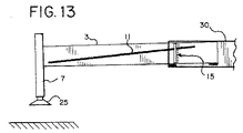
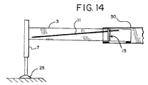
図9〜14は、アウトリガビームとジャッキとが種々の位置において使用されるときに、好ましい実施形態の装置による測定がどのようにしてなされるか、すなわち、アウトリガビームが完全に引っ込んだ位置(図9〜10)から、ビームが部分的に伸長した位置(図11〜12)まで、及びアウトリガビームが一杯まで伸長した位置(図13〜14)において、装置による測定がどのようにしてなされるかを示している。 FIGS. 9-14 illustrate how measurements by the apparatus of the preferred embodiment are made when the outrigger beam and jack are used in various positions, i.e., the position where the outrigger beam is fully retracted (FIG. 9-10) how the measurement is done by the device from the position where the beam is partially extended (FIGS. 11-12) and the position where the outrigger beam is fully extended (FIGS. 13-14) Is shown.
図9及び10に示されているビームが引っ込められている状態では、磁気センサーによる測定値は、ジャッキが持ち上げられている状態(図9)でのセンサーの読み“9”から、ジャッキが降ろされている状態(図10)でのセンサーの読み“8”へと移る。図11及び12に示されているビームが部分的に伸長せしめられている状態においては、磁気センサーによる測定値は、ジャッキが持ち上げられている状態(図11A)での読み“6”から、ジャッキが降ろされている状態(図12A)での読み“5”へと移る。図13及び14に示されているビームが一杯まで伸長せしめられている状態においては、磁気センサーによる測定値は、ジャッキが持ち上げられている状態(図13)での読み“3”から、ジャッキが降ろされている状態(図14)での読み“2”へと移る。 9 and 10, when the beam is retracted, the readings from the magnetic sensor are taken down from the sensor reading “9” when the jack is lifted (FIG. 9). The reading proceeds to “8” when the sensor is in a state of being in contact (FIG. 10). In the state where the beam shown in FIGS. 11 and 12 is partially extended, the measured value by the magnetic sensor is determined from the reading “6” in the state where the jack is lifted (FIG. 11A). The process proceeds to the reading “5” in the state where the mark is lowered (FIG. 12A). In the state where the beam shown in FIGS. 13 and 14 is extended to the full, the measured value by the magnetic sensor is from the reading “3” in the state where the jack is lifted (FIG. 13). The process proceeds to reading “2” in the state of being lowered (FIG. 14).
ここに記載し且つ図面に示したセンサーに関連する上記の読みの数字は、図示説明及び明確化の目的のためのみのものであると理解されるべきである。磁気センサーは、磁気ストリップがセンサーを横切る点を示す信号を発生し、このような信号を、クレーンの動作を監視し且つ/又は制御するための装置に供給することができる。図9〜14に図示されている磁気ストリップがセンサーと交差する点の視覚的に認識できる指標が、所望ならば任意に提供され得る。このような指標の目盛は、いずれもが任意のものであり且つ上記したものに限定されるものではない。 It should be understood that the above reading numbers relating to the sensors described herein and shown in the drawings are for illustration and clarity purposes only. The magnetic sensor generates a signal indicating the point at which the magnetic strip crosses the sensor, and such a signal can be provided to a device for monitoring and / or controlling crane operation. A visually recognizable indication of where the magnetic strip illustrated in FIGS. 9-14 intersects the sensor may optionally be provided if desired. The scales of such indexes are all arbitrary and are not limited to the above.
また、一連の不連続な磁気的な点が連続ストリップの代わりに使用されている場合には、ジャッキが持ち上げられるか降ろされるときに、該一連の不連続な点のうちの1つがセンサー位置にある限り、センサーと比較された検知点の動きは依然としてジャッキが降ろされたか持ち上げられたかを示す表示を堤供する。 Also, if a series of discrete magnetic points are used instead of a continuous strip, one of the series of discrete points will be at the sensor position when the jack is raised or lowered. As long as there is, the movement of the detection point compared to the sensor still provides an indication of whether the jack has been lowered or lifted.
従って、当該好ましい実施形態の磁気センサーの配列は、伸縮式アウトリガビームがアウトリガボックスから伸長せしめられている伸長度合いを判定する機能を果し、それによって、クレーンの監視/制御装置がクレーン装置の残りの部分に対するアウトリガジャッキの位置を特定することができるようにすることがわかる。該好ましい実施形態の装置はまた、ジャッキが降ろされたことを検知し且つジャッキがクレーンを支持していることを示す信号を堤供する。これは、クレーンの状態の自動監視と好ましい実施形態の装置によって提供される信号に応じた適当な制御とを補助する。 Thus, the magnetic sensor arrangement of the preferred embodiment serves to determine the extent to which the telescopic outrigger beam has been extended from the outrigger box so that the crane monitoring / control device can be It can be seen that the position of the outrigger jack relative to the portion can be specified. The apparatus of the preferred embodiment also provides a signal that senses that the jack has been lowered and indicates that the jack is supporting the crane. This assists in automatic monitoring of crane status and appropriate control in response to signals provided by the apparatus of the preferred embodiment.
以上においては、1以上の磁気ストリップ11,13又はその他の一連の磁気的な点及び1以上の磁気センサー15,17を含む組み合わせを含んでいる本発明を説明した。しかしながら、本発明はこのような構成要素の使用に限定されない。所望の新規な結果を達成するために、他のタイプのセンサー構造を本発明に従って使用することができる。
The foregoing has described the present invention including one or more
磁気スイッチのアレイを含んでいるセンサーを、上記した磁気センサーの代わりにアウトリガボックスにおいて使用することができる。磁気ストリップ11,13又はその他の形態の一連の磁気的な点が、ここに記載したアウトリガビーム上で対角状に使用される。MagnasphereによるモデルMG−A2−1.5Nのような磁気スイッチのアレイは上記センサー15,17の代わりとして適切である。
A sensor including an array of magnetic switches can be used in the outrigger box instead of the magnetic sensor described above. A series of
一つの代替的な組合せとして、電流を流すワイヤーと該ワイヤーの位置を判定するセンサーとの組合せがある。このような実施形態においては、前記の一連の検知点は、各々、アウトリガビーム上に同様にして配列されているワイヤーに沿った点を備えている。ワイヤーに関連付けられている電流源は、電流をワイヤーの中に流れさせる。代替的な実施形態は、各磁気センサー15,17の代わりに、ビームがアウトリガボックスから又は該アウトリガボックス内へと伸ばされるときに電流が流れているワイヤーの位置を判定するための電流センサーの配列を含んでいる。ビームに沿って延びているワイヤー内の電流を測定するために使用することができる機器の例は、ハネウェルによって製造されている電流センサーモデルHMC1051Zである。このHMC1051Zは、磁気抵抗技術に基づいた磁気/電流センサーである。これらのセンサーの垂直なアレイは、該センサーの近くを通っているワイヤーを流れる電流によって生じる磁場を検知するために使用することができる。
As an alternative combination, there is a combination of a wire for passing a current and a sensor for determining the position of the wire. In such an embodiment, each of the series of detection points comprises a point along the wire that is similarly arranged on the outrigger beam. A current source associated with the wire causes current to flow through the wire. In an alternative embodiment, instead of each
本発明の更にもう一つ別の実施形態は、鉄系金属と非鉄系金属とを区別することができるセンサーを備えている。アウトリガボックス及びアウトリガビームは、通常は、鉄系金属である鋼によって製造される。代替的な実施形態は、各磁気ストリップ11,13の代わりに、非鉄系金属からなる細長いストリップ、又は上記したように対角状にアウトリガビーム上に配列されている一連の非鉄系金属を備えることができる。この実施形態におけるセンサー15及び17の各アレイは、金属の2つのタイプを区別できるセンサーのアレイからなる。鉄系金属/非鉄系金属の選択的な検知機能を有する誘導近接スイッチは、Pepperl+Fuchs GmbHから入手可能である。これらの近接スイッチは2つの別個の出力を備えている。一方の出力は鉄系金属の検知信号を出力し、もう一つの出力は非鉄系金属の検知信号を出力する。このような近接スイッチのアレイによると、アウトリガビームの鉄系金属と該ビームに沿って位置決めされている非鉄系金属とを区別して、該非鉄系金属ストリップの位置とビームの対応する位置とを判定することができる。このようにして、センサーアレイは、上記したように、アウトリガボックスに対するビームとアウトリガとの位置を検知することができる。
Yet another embodiment of the present invention includes a sensor capable of distinguishing between ferrous metals and non-ferrous metals. The outrigger box and the outrigger beam are usually made of steel, which is a ferrous metal. Alternative embodiments comprise, instead of each
当該代替的な実施形態の素子において光センサー技術を利用することができる2つの可能な方法がある。第一の実施形態においては、本発明は、各センサー15,17の位置に反射型光センサーのアレイを備えている。各光センサーは、一つのパッケージ内にエミッタとレシーバとを備えている。このような素子の例はパナソニックのCNB1009(ON2173)である。これらの素子は、既に記載したように、アウトリガボックス上に概ね垂直アレイ状に配列される。一連の反射性の検知点又は反射性材料のストリップが、代わりに且つ磁気ストリップの形態で接着される。該アレイ内の種々のセンサーは、ビームがアウトリガボックスから伸長せしめられたりアウトリガボックス内へと引っ込められたりするときに、各センサーに対して反射性のストリップの配置に依存する低い読みと高い読みとを有しており、比較的高い読みはセンサーのうちの一つに隣接して反射性ストリップが存在していることを示す。代替的に、一連の検知点は、当てられた放射線を吸収する材料を備えることができる。この場合には、アレイ内のセンサーは、比較的低い読みを有する吸収点の近くであることを示す。
There are two possible ways in which photosensor technology can be utilized in the elements of the alternative embodiment. In the first embodiment, the present invention comprises an array of reflective photosensors at the position of each
本発明において光学技術を利用するための第二の選択肢は、磁気ストリップ11,13の位置においてアウトリガビーム上に一連の発光点を位置決めすることである。発光点は、種々の技術とすることができ、該技術としては、ビームに接着されるかさもなければ取り付けられた恐らくはストリップ形状のLED及び光ファイバ素子がある。この構造においては、センサー15,17は、光源の存在/近接を検知するフォトダイオード又はトランジスタのアレイからなる。フォトダイオードの一例はOSRAM SFH2O3FAである。これらの素子は、小さく且つ容易に入手可能であり、上記したようにビームがアウトリガボックスから伸長せしめられるか又はアウトリガボックス内へと引っ込められるときに前記の発光点の位置を検知するために使用することができるアレイ内に封入することができる。
A second option for utilizing optical technology in the present invention is to position a series of emission points on the outrigger beam at the location of the
アウトリガビーム上の反射性の検知点又は発光点の使用はまた、伸長せしめられたアウトリガの高い視認性を提供できるという付加的な利点をも有している。 The use of reflective sensing or emission points on the outrigger beam also has the added advantage of providing high visibility of the extended outrigger.
上記したように、アウトリガビームの長さを示す信号と、アウトリガジャッキが降下位置にあってクレーンを支持していることを示す信号とは、コントローラに供給される。コントローラは、このような情報を記憶し、測定のための補正値を含むルックアップ表を参照する。すなわち、逆さジャッキが種々のビームの伸長長さに対してクレーンを支持しているという検知を行うために、(ビームがアウトリガの使用中の力に応答する方法をもたらすビームの構造的特徴に基づいた)各アウトリガビームについての適切なデータを含むルックアップ表が記憶される。 As described above, the signal indicating the length of the outrigger beam and the signal indicating that the outrigger jack is in the lowered position and supports the crane are supplied to the controller. The controller stores such information and references a look-up table that includes correction values for measurement. That is, to detect that an inverted jack is supporting the crane for various beam extension lengths (based on beam structural features that provide a way for the beam to respond to forces during use of the outriggers). A) a look-up table containing the appropriate data for each outrigger beam is stored.
例示的な実施形態においては、各アウトリガビームについて2つのルックアップ表が設けられている。第一のルックアップ表はアウトリガビームの伸長又は短縮に関する値を記憶している。第二のルックアップ表はジャッキの位置に関する値を記憶している。 In the exemplary embodiment, two lookup tables are provided for each outrigger beam. The first look-up table stores values relating to the extension or shortening of the outrigger beam. The second look-up table stores values related to jack position.
制御装置のための制御論理の例が以下に示す表に提供されている。ビームの伸長又は短縮の機能(ビームの伸長)は、ビームが所望の位置へ移動されるまで行われる(最大の伸長、50%の伸長、又は0%の伸長についてのデータが提供されているが、所望に応じて他の或いは追加の値が提供され得る)。センサーによって検知された実際のビームの伸長長さが設定され且つ記憶される。ジャッキ伸長機能(ジャッキの伸長)が実行されている間は、制御装置はセンサーの出力を連続的に監視する。制御装置が検知された出力の中に予期される変化を検知したとき、ジャッキはクレーンを支持している(ジャッキ支持−yes)と判定される。ジャッキの更なる伸長又は短縮は、センサーの出力に変化をもたらさず、ジャッキがクレーンを支持しているという状態が設定される。一方、センサーの出力がクレーンが支持されていない場合に予期される値まで変化したとき、制御装置は、アウトリガ及びジャッキが最早クレーンを支持していないという状態(ジャッキ支持−no)を設定する。

アウトリガビームが記憶されている長さに設定されている限り、オペレータはジャッキの位置を変える操作をすることができる。しかしながら、ジャッキの位置は、センサーが位置の変化を検知するまではコントローラによって判定されない。 As long as the outrigger beam is set to the stored length, the operator can change the position of the jack. However, the position of the jack is not determined by the controller until the sensor detects a change in position.
また、ジャッキがリークして持ち上がり始め且つ最早クレーンを支持しない高さまで持ち上がると、センサーの出力は、クレーンが支持されていない状態に関連付けられた値へと自動的に変わる。変化した状態を示す信号がオペレータに提供され、この状態及びジャッキを検査し且つ/又は交換する必要性が指示される。 Also, if the jack begins to leak and begin to lift and lifts to a height that no longer supports the crane, the sensor output automatically changes to the value associated with the unsupported crane. A signal indicating the changed condition is provided to the operator, indicating the condition and the need to inspect and / or replace the jack.
同様の方法で、クレーンブーム上の荷のような力によってクレーンが傾き始めると、荷が無い側のアウトリガが地面から持ち上げられる状況が起こり得る。このような場合には、コントローラは、(クレーンを最早支持していない)ジャッキが持ち上げられた状態への変化を示す信号を受け取り且つこの情報を使用してオペレータにこの状態を表す信号を送り且つクレーンの動きを制限することができる。 In a similar manner, when the crane begins to tilt due to a load-like force on the crane boom, a situation can occur where the outrigger on the side with no load is lifted from the ground. In such a case, the controller receives a signal indicating the change to the raised state of the jack (which no longer supports the crane) and uses this information to send a signal to the operator to indicate this state and The movement of the crane can be restricted.
同様に、コントローラは、各々のジャッキを監視し且つクレーンに対する荷重の位置即ちある時点で荷重がどちら側にあるかを絶えず判定する。荷重の位置についてのこの情報に基づいて、コントローラは、各々のアウトリガジャッキの伸長状態の適合性を連続して評価する。これらの種々の方法によって、コントローラは、センサーの出力信号を連続的に監視して作動中にクレーンがずれたか否かを判定する。 Similarly, the controller monitors each jack and constantly determines the position of the load on the crane, i.e., which side the load is on at some point. Based on this information about the position of the load, the controller continuously evaluates the suitability of the extension state of each outrigger jack. With these various methods, the controller continuously monitors the sensor output signal to determine if the crane has been displaced during operation.
上に開示されている実施形態は、アウトリガビームが引っ込められた位置(0%)、最大まで伸長された位置(100%)、及び部分的に伸長せしめられた位置(50%)を参考のために記載している。しかしながら、本発明はこれら3つの伸長長さに限定されない。当該好ましい実施形態の測定装置は、ビームの伸長長さの全てを監視することができる。 The embodiments disclosed above are referenced for the position where the outrigger beam is retracted (0%), the position extended to the maximum (100%), and the position extended partially (50%). It is described in. However, the present invention is not limited to these three extension lengths. The measuring device of the preferred embodiment can monitor all of the extended length of the beam.
上記したように、該好ましい実施形態の装置における磁気的な読み又は他のセンサーの読みの変化は、アウトリガジャッキが地面に接しており且つクレーンを支持していることを示す指示を提供するであろう。しかしながら、上記の読みの変化は、ホイール/タイヤが地面から全く持ち上げられた形態でジャッキがクレーンを支持しているか否か、又はたとえジャッキがクレーンを支持していてもホイールが依然として地面と接しているか否か、を終局的に確認することはできないかも知れない。当該好ましい実施形態の使用と矛盾することがない形態で他の手段を使用して、アウトリガが下げられたとき及びホイール/タイヤがクレーンの重量の幾らかを依然として支持しているか、さもなければ依然として地面と接しているか否かを検知しても良い。 As noted above, a change in magnetic reading or other sensor reading in the preferred embodiment apparatus will provide an indication that the outrigger jack is touching the ground and supporting the crane. Let's go. However, the change in reading above is whether the wheel / tire is lifted off the ground and whether the jack is supporting the crane, or even if the jack is supporting the crane, the wheel is still in contact with the ground. It may not be possible to finally confirm whether or not. Using other means in a manner consistent with the use of the preferred embodiment, when the outrigger is lowered and the wheel / tire is still supporting some of the crane's weight, or still It may be detected whether or not it is in contact with the ground.
トルクが少しかかったときにホイール/タイヤが回転したか否かを判定するために、ABSセンサーのような検知方法を使用しても良い。ホイール/タイヤが回転した場合には、次いでタイヤは地面から離れる。また、コントローラは、ホイールの回転のチェックが開始されるときにブレーキがかけられていないことを判定する。 A detection method such as an ABS sensor may be used to determine whether the wheel / tire has rotated when a little torque is applied. If the wheel / tire rotates, the tire then leaves the ground. The controller also determines that the brake is not applied when the wheel rotation check is started.
代替的に、クレーンのフレーム又はシャシ上の既知の点から地面までの距離を検知するために、多数の検知素子を使用しても良い。検知された距離がホイール/タイヤが地面上にあった場合の距離よりも長い場合には、次いで、ホイール/タイヤは地面から離れる。 Alternatively, multiple sensing elements may be used to sense the distance from a known point on the crane frame or chassis to the ground. If the sensed distance is longer than the distance when the wheel / tire is on the ground, then the wheel / tire is then removed from the ground.
更に別の代替例として、ホイール/タイヤが空中に吊り下げられているか否かを判定するために、長さ測定素子をホイールサスペンションと組み合わせたサスペンションストラット又はエアーバッグ内で使用しても良い。 As yet another alternative, the length measuring element may be used in a suspension strut or airbag in combination with a wheel suspension to determine whether the wheel / tire is suspended in the air.
更に、ジャッキがクレーンを支持しているか否かを判定するプロセスは、本発明のビーム伸長度検知という機能が無い状態で使用されるであろうと言うことも理解できるであろう。この場合には、クレーンは、依然として、ジャッキが取り付けられている少なくとも1つのアウトリガを備えているであろう。アウトリガ長さ測定装置の場合と同様に、アウトリガは、アウトリガ支持部に対して移動軸線に沿って可動のビームを備えている。該ビームは、クレーンの重量がジャッキに近づく方向又は遠ざかる方向に移動すると、支持部に対して若干上下に動く機能を有している。この装置は、アウトリガが所望の作動位置にあるときにクレーンを支持するために、作動ジャッキが伸長せしめられて地面と係合しているか否かを判定するであろう。この点に関して、“所望の作動位置”という用語は、クレーンのオペレータが、ジャッキがクレーンを支持しているか否かを知りたがっているアウトリガの位置を意味している。例えば、ビームの最大引っ込み位置、ビームの最大伸長位置、及び中間の伸長位置、のような1以上の位置がある。該装置は、ビームか支持部かのいずれか一方に取り付けられている少なくとも1つの検知点と、前記ビームか前記支持部かのいずれか他方における前記アウトリガビームが所望の作動位置にあるときに少なくとも1つの検知点の位置を検知することができる位置に取り付けられているセンサーと、を備えている。該センサーは、ビームが前記支持部に対して上下に動くときに前記検知点の位置を検知する。このようにして、ジャッキがクレーンのための支持部を提供しているか否かを示す信号が発生される。もちろん、図6〜14に関して上記した本発明の好ましい実施形態のセンサー及び磁気ストリップは、少なくとも1つの検知点とセンサーとを提供するために使用することができる。 It will further be appreciated that the process of determining whether a jack is supporting a crane will be used without the beam extension detection feature of the present invention. In this case, the crane will still have at least one outrigger to which a jack is attached. As in the case of the outrigger length measuring device, the outrigger includes a beam that is movable along the movement axis with respect to the outrigger support. The beam has a function of moving up and down slightly with respect to the support portion when the weight of the crane moves in a direction approaching or moving away from the jack. This device will determine if the actuation jack is extended and engaged with the ground to support the crane when the outrigger is in the desired actuation position. In this regard, the term “desired operating position” refers to the position of the outrigger where the crane operator wants to know if the jack is supporting the crane. For example, there are one or more positions such as a maximum retracted position of the beam, a maximum extended position of the beam, and an intermediate extended position. The apparatus includes at least one sensing point attached to either the beam or the support and at least when the outrigger beam on either the beam or the support is in a desired operating position. And a sensor attached to a position capable of detecting the position of one detection point. The sensor detects the position of the detection point when the beam moves up and down with respect to the support portion. In this way, a signal is generated that indicates whether the jack is providing support for the crane. Of course, the sensors and magnetic strips of the preferred embodiment of the present invention described above with respect to FIGS. 6-14 can be used to provide at least one sensing point and sensor.
本発明においては、作業現場においてクレーンを設置するときに、クレーン制御装置の安全性に関する機構を自動化することができる。アウトリガが伸長せしめられる伸長度合いに関するデータをオペレータが手動によって入力する代わりに、センサーからの信号が入力として直接供給される。また、本発明は、最大伸長位置と最大短縮位置との間の中間伸長位置の全てについての入力を容易に得ることができる。 In this invention, when installing a crane in a work site, the mechanism regarding the safety | security of a crane control apparatus can be automated. Instead of the operator manually entering data regarding the extent to which the outrigger is extended, the signal from the sensor is supplied directly as input. In addition, the present invention can easily obtain input for all intermediate extension positions between the maximum extension position and the maximum shortened position.
ここに記載されている現在のところ好ましい実施形態に対する種々の変更及び改造は当業者にとって明らかであるということは理解されるべきである。例えば、本発明は、車体にアウトリガが装備されている場合のクローラクレーンにおいて使用することもできる。このような変更及び改造は、本発明の精神及び範囲から逸脱することなく且つ本発明が意図している利点を減らすことなく行うことができる。従って、このような変更及び改造は添付の特許請求の範囲によって保護されることが意図されている。 It should be understood that various changes and modifications to the presently preferred embodiments described herein will be apparent to those skilled in the art. For example, the present invention can be used in a crawler crane when the vehicle body is equipped with an outrigger. Such changes and modifications can be made without departing from the spirit and scope of the present invention and without diminishing its intended advantages. Accordingly, it is intended that such changes and modifications be protected by the appended claims.
3 第一のアウトリガビーム、
5 第二のアウトリガビーム、
7 逆さジャッキ、
9 逆さジャッキ、
11 第一の磁気ストリップ、
13 第二の磁気ストリップ、
15 第一の磁気センサー、
17 第二の磁気センサー、
19 タイヤ、
21 タイヤ、
25 アウトリガパッド、
27 アウトリガパッド、
30 アウトリガボックス、
50 クレーン、
51 伸縮式ブーム、
53 キャリアユニット、
55 上部旋回体、
60 アウトリガ装置、前方のアウトリガの組、
62 後方のアウトリガの組、
a,a’,b,b’ 作用点、
C クレーン、
M ビームの質量、
3 First outrigger beam,
5 Second outrigger beam,
7 Upside down jack,
9 Upside down jack,
11 The first magnetic strip,
13 Second magnetic strip,
15 First magnetic sensor,
17 Second magnetic sensor,
19 tires,
21 tires,
25 Outrigger pad,
27 Outrigger pad,
30 Outrigger box,
50 cranes,
51 telescopic boom,
53 carrier units,
55 Upper swing body,
60 outrigger device, front outrigger set,
62 A set of rear outriggers,
a, a ′, b, b ′ points of action,
C crane,
M beam mass,
Claims (17)
コントローラと、
支持部、及び該支持部に対して移動軸線に沿って可動であるビームを有する少なくとも1つのアウトリガと、
前記ビームに搭載されたジャッキであって、選択的に伸長して支持面と接して当該クレーンを支持可能であり、当該クレーンの重量が前記ジャッキに近づく方向又は前記ジャッキから離れる方向に移動したときに前記支持部に対して少量だけ上下に動くようにされたジャッキと、
前記アウトリガの伸長の程度を判定するとともに、前記アウトリガが所望の作業位置にあるときに前記ジャッキが伸長されて前記クレーンを支持するように前記支持面に係合しているか否かを判定する非機械式装置と、を備え、
前記非機械式装置が、
a)前記移動軸線に対して非平行な向きで前記ビームか前記支持部かのどちらか一方に取り付けられている一連の検知点と、
b)前記ビームが前記移動軸線に沿って移動する間において前記一連の検知点を異なる位置で横切るようにして、前記ビームか前記支持部かのどちらか他方に取り付けられている非機械式センサーと、を備えており、
c)前記非機械式センサーは、前記ビームが前記移動軸線に沿って動くときに前記一連の検知点の位置を検知し、
d)前記非機械式センサーは、該非機械式センサーが検知した前記支持部に対する前記ビームの相対位置を示す第一の信号、及び前記ジャッキが前記支持面と係合して当該クレーンを支持していることを示す第二の信号を前記コントローラに提供する、ことを特徴とするクレーン。 I crane der,
A controller,
At least one outrigger having a support and a beam movable relative to the support along a movement axis ;
A jack mounted on the beam, which can be selectively extended to support the crane in contact with a support surface, and the weight of the crane moves in a direction approaching the jack or away from the jack A jack adapted to move up and down by a small amount relative to the support part;
Non-determining whether or not the outrigger is extended and determining whether the jack is extended and engaged with the support surface to support the crane when the outrigger is in a desired working position. A mechanical device,
The non-mechanical device is
a) a series of detection points attached to either the beam or the support in an orientation non-parallel to the axis of movement;
b) a non-mechanical sensor attached to either the beam or the support so as to traverse the series of sensing points at different positions while the beam moves along the axis of movement ; , And
c) the non-mechanical sensor detects the position of the series of detection points as the beam moves along the axis of movement ;
d) said non-mechanical sensor, a first signal indicating the relative position of said beam relative to said support portion to which the non-mechanical sensor has detected, and the jack is engaged with the supporting surface supporting the crane Providing the controller with a second signal indicating that the
前記一連の検知点が磁気ストリップからなり、前記非機械式センサーが磁気センサーである、ことを特徴とするクレーン。 The crane according to claim 1 ,
The crane characterized in that the series of detection points are magnetic strips, and the non-mechanical sensor is a magnetic sensor.
前記一連の検知点が磁気ストリップからなり、前記非機械式センサーが磁気スイッチのアレイからなる、ことを特徴とするクレーン。 The crane according to claim 1,
A crane, wherein the series of sensing points comprises a magnetic strip and the non-mechanical sensor comprises an array of magnetic switches.
前記一連の検知点が電流を流すワイヤーからなり、前記非機械式センサーが電流を検知する機器のアレイからなる、ことを特徴とするクレーン。 The crane according to claim 1,
The crane characterized in that the series of detection points is made of a wire through which a current flows, and the non-mechanical sensor is made of an array of devices for detecting the current.
前記ビームが鉄系金属によって構成されており、前記一連の検知点が非鉄系金属によって構成されており、前記非機械式センサーが鉄系金属と非鉄系金属とを区別する素子のアレイからなる、ことを特徴とするクレーン。 The crane according to claim 1,
The beam is made of ferrous metal, the series of detection points are made of non-ferrous metal, and the non-mechanical sensor is composed of an array of elements that distinguish ferrous metal from non-ferrous metal, A crane characterized by that.
前記一連の検知点が、光反射性材料、光吸収性材料、及びこれらの組合せからなる群から選択された材料からなり、前記非機械式センサーが光センサーのアレイからなる、ことを特徴とするクレーン。 The crane according to claim 1,
The series of detection points is made of a material selected from the group consisting of a light-reflective material, a light-absorbing material, and combinations thereof, and the non-mechanical sensor is made of an array of light sensors Crane .
前記一連の検知点が細長い発光素子からなり、前記非機械式センサーが光センサーのアレイからなる、ことを特徴とするクレーン。 The crane according to claim 1,
The crane according to claim 1, wherein the series of detection points is composed of elongated light emitting elements, and the non-mechanical sensor is composed of an array of optical sensors.
前記第二の信号が、前記第一の信号に続いて且つ前記ジャッキが前記支持面と接するように伸長せしめられた後に引き続いて提供され、前記第二の信号は、前記移動軸線を横切る方向に前記ジャッキによって前記ビームにかけられる力の結果として、前記支持部に対する前記ビームの位置の相対的な変化を示している、ことを特徴とするクレーン。 It is a crane as described in any one of Claims 1-7 ,
The second signal is provided subsequently to the first signal and after the jack has been extended to contact the support surface, the second signal in a direction across the axis of movement. A crane showing a relative change in the position of the beam relative to the support as a result of the force exerted on the beam by the jack.
前記クレーンを選択的に支持するために多数のアウトリガを備えており、各アウトリガが、支持部と、移動軸線に沿って該支持部に対して可動のビームとを備えており、且つ前記移動軸線に対して非平行な向きで前記ビームか前記支持部かのいずれか一方に取り付けられている一連の検知点と、前記ビームが前記軸線に沿って移動する際に種々の位置で前記一連の検知点を横切る方向で前記ビームか前記支持部かのいずれか他方に取り付けられている非機械式センサーとを有している、ことを特徴とするクレーン。 The crane according to any one of claims 1 to 8 ,
It comprises a number of outriggers for selectively supporting the crane, each outrigger, and a support portion, and a movable beam with respect to the support part along the movement axis, and the axis of movement A series of sensing points attached to either the beam or the support in a non-parallel orientation and the series of sensing at various positions as the beam moves along the axis. A crane having a non-mechanical sensor attached to either the beam or the support in a direction crossing a point.
前記一連の検知点が前記ビームの表面上を対角線に沿って延びており、前記非機械式センサーは、前記支持部に取り付けられており且つ直線状で前記ビームの移動軸線に対して概ね直角である、ことを特徴とするクレーン。 It is a crane as described in any one of Claims 1-9 ,
The series of sensing points extend diagonally over the surface of the beam, and the non-mechanical sensor is attached to the support and is linear and generally perpendicular to the beam's axis of movement. A crane characterized by being.
前記コントローラが、前記第一の信号と前記第二の信号との間の差によって表される直線位置を表す出力の予期される変化を検知したときに、該コントローラは前記ジャッキが該クレーンを支持していると判定する、ことを特徴とするクレーン。 The crane according to any one of claims 1 to 7 ,
Said controller, upon detecting the expected change in the output representing the linear position represented by the difference between said first signal and said second signal, said controller supports the jack the crane It is judged that it is carrying out, The crane characterized by the above-mentioned.
前記コントローラが前記非機械式センサーの出力信号を連続的に監視して該クレーンが作業中に位置を変えたか否かを判定する、ことを特徴とするクレーン。 The crane according to claim 11 ,
A crane wherein the controller continuously monitors the output signal of the non-mechanical sensor to determine whether the crane has changed position during work.
a)一連の検知点を、前記移動軸線と非平行な向きで前記ビームか前記支持部かのどちらか一方に取り付けるステップと、
b)非機械式センサーを、前記ビームが前記移動軸線に沿って移動する間において前記一連の検知点を異なる位置において横切るようにして、前記ビームか前記支持部かのどちらか他方に対して関連付けるステップと、
c)前記ビームが前記移動軸線に沿って移動するときに、前記一連の検知点の位置を前記非機械式センサーによって検知するステップと、
d)前記非機械式センサーによって検知された前記支持部に対する前記ビームの相対位置を示す第一の信号を前記非機械式センサーから提供し、前記移動軸線に交わる方向での前記ビームに作用する力による前記支持部に対する前記ビームの位置の相対的変化を示す第二の信号を前記非機械式センサーから提供するステップと、
を含む方法。 Non-mechanically determining a position for a beam relative to a support, the beam being movable along a movement axis relative to the support;
a) attaching a series of detection points to either the beam or the support in an orientation non-parallel to the axis of movement;
b) associating a non-mechanical sensor with either the beam or the support, such that it traverses the series of sensing points at different positions while the beam moves along the axis of movement. Steps,
c) detecting the position of the series of detection points by the non-mechanical sensor as the beam moves along the axis of movement;
d) said providing a first signal indicative of a relative position of said beam relative to said support portion which is detected by the non-mechanical sensor from the non-mechanical sensors, acting on the beam in a direction intersecting the axis of movement force Providing a second signal from the non-mechanical sensor indicative of a relative change in the position of the beam relative to the support according to
Including methods.
該クレーンは、コントローラと、少なくとも1つのアウトリガと、ジャッキとを備えており、該アウトリガは、支持部、及び該支持部に対して移動軸線に沿って可動のビームを備え、前記ジャッキは、前記ビームに搭載され、支持面に接触するまで選択的に伸長して当該クレーンを支持可能とされており、
a)前記移動軸線に対して非平行な向きで前記ビームか前記支持部かのいずれか一方に取り付けられた一連の検知点を設けるステップと、
b)前記ビームが前記移動軸線に沿って移動する間において異なる位置で前記一連の検知点を横切る方向で、前記ビームか前記支持部かのいずれか他方に取り付けられた非機械式センサーを設けるステップと、
c)前記ビームが前記移動軸線に沿って移動する際に、前記非機械式センサーに対する前記一連の検知点の位置を検知するステップと、
d)前記非機械式センサーによって検知された、前記支持部に対する前記ビームの相対位置を示す第一の信号を前記非機械式センサーから前記コントローラに提供するステップと、
e)前記ジャッキを支持面に係合するまで降ろして、前記ジャッキが前記支持面に係合して前記クレーンを支持していることを示す第二の信号を前記非機械式センサーから前記コントローラに提供するステップと、
を含むことを特徴とする方法。 A method of operating a crane,
The crane, a controller comprises at least one outrigger, and a jack, said outrigger includes a support portion, and along the axis of movement comprising a movable beam with respect to the support unit, the jack, the It is mounted on the beam and can be selectively extended until it touches the support surface to support the crane.
a) providing a series of detection points attached to either the beam or the support in a non-parallel orientation with respect to the axis of movement;
b) providing a non-mechanical sensor attached to either the beam or the support in a direction across the series of sensing points at different positions as the beam moves along the axis of movement ; When,
c) detecting the position of the series of detection points relative to the non-mechanical sensor as the beam moves along the axis of movement;
d) providing a first signal from the non-mechanical sensor to the controller that is detected by the non-mechanical sensor and indicating the relative position of the beam with respect to the support;
e) Lowering the jack until it engages a support surface and sending a second signal from the non-mechanical sensor to the controller indicating that the jack engages the support surface and supports the crane. Providing steps;
A method comprising the steps of:
前記第二の信号が、前記ジャッキによって前記移動軸線を横切る方向に前記ビームにかけられる力の結果としての前記支持部に対する前記ビームの相対位置変化を表している、ことを特徴とする方法。 15. A method according to claim 14 ,
The method wherein the second signal represents a change in the relative position of the beam relative to the support as a result of a force applied to the beam in a direction across the axis of movement by the jack.
前記第一及び第二の信号を前記クレーンのためのコントローラに付与し、前記第一の信号と前記第二の信号との差によって示される位置の出力変化を検知し、それによって前記ジャッキが前記クレーンを支持していると判定するステップと、を更に含んでいる、ことを特徴とする方法。 The method according to claim 14 or 15 ,
Grant said first and second signals to a controller for the crane, the detected output change of the position indicated by the difference between the first signal and the second signal, the jack the thereby Determining that the crane is being supported.
コントローラと、 A controller,
ジャッキを有する少なくとも1つのアウトリガと、 At least one outrigger having a jack;
前記クレーンに対する前記アウトリガの伸長の程度、及び支持面に対する前記ジャッキの係合状態を判定する非機械式装置と、を備え A non-mechanical device for determining a degree of extension of the outrigger with respect to the crane and an engagement state of the jack with respect to a support surface.
前記アウトリガが、支持部と、該支持部に対して移動軸線に沿って移動可能なビームとを有しており、 The outrigger includes a support and a beam movable relative to the support along a movement axis;
前記非機械式装置が、 The non-mechanical device is
a)前記移動軸線に対して非平行な向きで前記ビームか前記支持部かのどちらか一方に取り付けられている一連の検知点と、 a) a series of detection points attached to either the beam or the support in an orientation non-parallel to the axis of movement;
b)前記ビームが前記移動軸線に沿って移動する間において非機械的な前記一連の検知点を異なる位置で横切るようにして、前記ビームか前記支持部かのどちらか他方に取り付けられている非機械式センサーと、を備えており、 b) non-mechanically attached to either the beam or the support so as to traverse the non-mechanical series of sensing points at different positions while the beam moves along the axis of movement. A mechanical sensor,
c)前記非機械式センサーは、前記ビームが前記移動軸線に沿って動くときに前記一連の検知点の位置を検知し、 c) the non-mechanical sensor detects the position of the series of detection points as the beam moves along the axis of movement;
d)前記非機械式センサーは、前記コントローラに該非機械式センサーが検知した前記支持部に対する前記ビームの相対位置を示す第一の信号、及び前記ジャッキの係合状態を示す第二の信号を提供する、ことを特徴とするクレーン。 d) The non-mechanical sensor provides the controller with a first signal indicating a relative position of the beam with respect to the support detected by the non-mechanical sensor, and a second signal indicating the engagement state of the jack. A crane characterized by that.
Applications Claiming Priority (3)
| Application Number | Priority Date | Filing Date | Title |
|---|---|---|---|
| US13/100,758 US8881919B2 (en) | 2011-05-04 | 2011-05-04 | System for measuring length of a beam extension and detecting support |
| US13/100,758 | 2011-05-04 | ||
| PCT/US2012/035477 WO2012151125A2 (en) | 2011-05-04 | 2012-04-27 | System for measuring length of a beam extension and detecting support |
Publications (2)
| Publication Number | Publication Date |
|---|---|
| JP2014513025A JP2014513025A (en) | 2014-05-29 |
| JP5913570B2 true JP5913570B2 (en) | 2016-04-27 |
Family
ID=47089534
Family Applications (1)
| Application Number | Title | Priority Date | Filing Date |
|---|---|---|---|
| JP2014509327A Active JP5913570B2 (en) | 2011-05-04 | 2012-04-27 | Crane and method of operating crane |
Country Status (10)
| Country | Link |
|---|---|
| US (1) | US8881919B2 (en) |
| EP (1) | EP2704977B1 (en) |
| JP (1) | JP5913570B2 (en) |
| CN (1) | CN103648957B (en) |
| BR (1) | BR112013028363A2 (en) |
| CA (1) | CA2834844A1 (en) |
| ES (1) | ES2620309T3 (en) |
| IN (1) | IN2013CN09017A (en) |
| RU (1) | RU2013153732A (en) |
| WO (1) | WO2012151125A2 (en) |
Families Citing this family (23)
| Publication number | Priority date | Publication date | Assignee | Title |
|---|---|---|---|---|
| DE102010056584B4 (en) * | 2010-12-30 | 2018-03-29 | Asm Automation Sensorik Messtechnik Gmbh | Mobile work machine |
| EP2573039A3 (en) * | 2011-09-23 | 2013-06-26 | Manitowoc Crane Companies, LLC | Outrigger monitoring system and methods |
| US9365398B2 (en) * | 2012-10-31 | 2016-06-14 | Manitowoc Crane Companies, Llc | Outrigger pad monitoring system |
| CN103043582B (en) * | 2012-12-30 | 2015-04-15 | 浙江鼎力机械股份有限公司 | Tilt-preventing support device of aerial work platform |
| CN103043576B (en) * | 2012-12-30 | 2015-04-15 | 浙江鼎力机械股份有限公司 | Scissor fork type anti-tilt supporting aerial work platform |
| CN103043579B (en) * | 2012-12-30 | 2015-05-20 | 浙江鼎力机械股份有限公司 | Aluminum alloy double-mast column anti-tilt support aerial work platform |
| CN103043578B (en) * | 2012-12-30 | 2015-05-20 | 浙江鼎力机械股份有限公司 | Aluminum alloy single-mast column anti-tilt support aerial work platform |
| CN103043574B (en) * | 2012-12-30 | 2015-05-20 | 浙江鼎力机械股份有限公司 | Tilting-proof supported aerial work platform base |
| US9550475B1 (en) * | 2015-09-09 | 2017-01-24 | Altec Industries, Inc. | Securely deploying outrigger foot |
| DE102016011189A1 (en) * | 2016-09-15 | 2018-03-15 | Liebherr-Werk Ehingen Gmbh | Device for stabilizing a crane |
| CN106495001A (en) * | 2016-11-08 | 2017-03-15 | 泸州汉硕信息科技有限公司 | Crane support load-bearing monitor system based on ess-strain technology |
| IT201700019360A1 (en) * | 2017-02-21 | 2018-08-21 | Manitou Italia Srl | Improved stabilizers for self-propelled operating machines |
| CN108120412B (en) * | 2018-01-24 | 2023-08-22 | 三一汽车制造有限公司 | Gap detection device and mechanical equipment |
| EP3543670B1 (en) * | 2018-03-02 | 2021-05-05 | Manitowoc Crane Companies, LLC | Outrigger pad assembly having a force sensor, an outrigger assembly and a lifting vehicle |
| CN108862037A (en) * | 2018-07-31 | 2018-11-23 | 徐州重型机械有限公司 | A kind of leg length measurement method of the crane based on light wave principle |
| US10875753B2 (en) | 2018-09-20 | 2020-12-29 | Manitou Equipment America, Llc | Telehandler boom extension monitoring system |
| GB201903399D0 (en) * | 2019-03-01 | 2019-04-24 | Bamford Excavators Ltd | A working machine and a controller |
| GB2582261B (en) | 2019-03-01 | 2023-06-21 | Bamford Excavators Ltd | Working machine |
| US20210154833A1 (en) * | 2019-11-22 | 2021-05-27 | Construction Robotics, Llc | Intuitive Control of Lifting Equipment |
| KR102298591B1 (en) * | 2020-06-09 | 2021-09-03 | 강정구 | Prevention device for disconnection of lead wire for outrigger |
| ZA202110395B (en) * | 2020-12-30 | 2023-11-29 | Manitou Italia Srl | Telehandler with facilitated alignment adjustment |
| CN114965050A (en) * | 2022-05-12 | 2022-08-30 | 佳诺威集团股份有限公司 | High density fiberboard strength detection device |
| GB2619764A (en) * | 2022-06-17 | 2023-12-20 | Caterpillar Inc | Automatic levelling of work machine |
Family Cites Families (12)
| Publication number | Priority date | Publication date | Assignee | Title |
|---|---|---|---|---|
| FR2339563A1 (en) * | 1976-01-27 | 1977-08-26 | Ppm Sa | TELESCOPIC STRUCTURE EQUIPPED WITH A DETECTOR OF THE RELATIVE POSITION OF TWO TRUNKS |
| JPH0732299Y2 (en) | 1989-11-29 | 1995-07-26 | 株式会社アイチコーポレーション | Outrigger overhang position detector |
| JPH03105188U (en) * | 1990-02-15 | 1991-10-31 | ||
| WO1995000372A1 (en) * | 1993-06-28 | 1995-01-05 | Kabushiki Kaisha Komatsu Seisakusho | Vehicle body levelling device for a working vehicle having outriggers |
| JPH08301578A (en) * | 1995-05-08 | 1996-11-19 | Aichi Corp | Automatic overhanging device for outrigger |
| JP2766232B2 (en) | 1995-10-27 | 1998-06-18 | 株式会社アイチコーポレーション | Jack grounding detector |
| JPH09156478A (en) * | 1995-12-04 | 1997-06-17 | Shin Meiwa Ind Co Ltd | Outrigger overhang position detecting device |
| US6712536B2 (en) * | 2001-10-09 | 2004-03-30 | Alps Electric Co., Ltd. | Printer |
| US7221151B2 (en) | 2003-01-31 | 2007-05-22 | Delphi Technologies, Inc. | Magnetic array position sensor |
| JP4068042B2 (en) * | 2003-10-27 | 2008-03-26 | 株式会社アイチコーポレーション | Work vehicle control device |
| JP2007283864A (en) | 2006-04-14 | 2007-11-01 | Furukawa Unic Corp | Outrigger extension detection device |
| JP5474617B2 (en) * | 2010-03-10 | 2014-04-16 | 株式会社モリタホールディングス | Outrigger jack device for aerial work vehicle |
-
2011
- 2011-05-04 US US13/100,758 patent/US8881919B2/en active Active
-
2012
- 2012-04-27 IN IN9017CHN2013 patent/IN2013CN09017A/en unknown
- 2012-04-27 CA CA2834844A patent/CA2834844A1/en not_active Abandoned
- 2012-04-27 BR BR112013028363A patent/BR112013028363A2/en not_active IP Right Cessation
- 2012-04-27 CN CN201280033223.7A patent/CN103648957B/en not_active Expired - Fee Related
- 2012-04-27 JP JP2014509327A patent/JP5913570B2/en active Active
- 2012-04-27 RU RU2013153732/11A patent/RU2013153732A/en not_active Application Discontinuation
- 2012-04-27 EP EP12779649.8A patent/EP2704977B1/en active Active
- 2012-04-27 WO PCT/US2012/035477 patent/WO2012151125A2/en active Application Filing
- 2012-04-27 ES ES12779649.8T patent/ES2620309T3/en active Active
Also Published As
| Publication number | Publication date |
|---|---|
| CA2834844A1 (en) | 2012-11-08 |
| EP2704977B1 (en) | 2017-02-01 |
| RU2013153732A (en) | 2015-06-10 |
| US8881919B2 (en) | 2014-11-11 |
| WO2012151125A3 (en) | 2013-01-17 |
| WO2012151125A2 (en) | 2012-11-08 |
| EP2704977A4 (en) | 2015-04-29 |
| US20120279938A1 (en) | 2012-11-08 |
| ES2620309T3 (en) | 2017-06-28 |
| CN103648957A (en) | 2014-03-19 |
| EP2704977A2 (en) | 2014-03-12 |
| CN103648957B (en) | 2017-02-08 |
| IN2013CN09017A (en) | 2015-08-07 |
| BR112013028363A2 (en) | 2017-01-24 |
| JP2014513025A (en) | 2014-05-29 |
Similar Documents
| Publication | Publication Date | Title |
|---|---|---|
| JP5913570B2 (en) | Crane and method of operating crane | |
| US9073739B2 (en) | Controller for restricting movement of a load handling apparatus | |
| JP5998204B2 (en) | Auto concrete pump | |
| US9365398B2 (en) | Outrigger pad monitoring system | |
| US9511985B2 (en) | Industrial truck with optical lifting height measurement | |
| US8779306B2 (en) | Weight sensing method and apparatus for forklifts | |
| JP2020059605A (en) | Machine, controller, and control method | |
| JP7189489B2 (en) | mobile cranes and crane systems | |
| US6779961B2 (en) | Material handler with electronic load chart | |
| JP7189490B2 (en) | Auxiliary device for position adjustment and mobile crane | |
| CN203602279U (en) | System for detecting pendency height of hook and crane | |
| US20230227300A1 (en) | Machine stability detection and indication for mobile lifting equipment | |
| JP6888519B2 (en) | Road-rail vehicle | |
| JP2019116348A (en) | Position adjustment devise, crane provided therewith and weight connecting method | |
| JPH09136799A (en) | Unmanned lift truck | |
| US20170217740A1 (en) | Crane for lifting and transporting loads comprising a roll-over protection system | |
| KR20160073248A (en) | Actual Height Checking Structure of Carriage for Forklift |
Legal Events
| Date | Code | Title | Description |
|---|---|---|---|
| A621 | Written request for application examination |
Free format text: JAPANESE INTERMEDIATE CODE: A621 Effective date: 20140606 |
|
| A977 | Report on retrieval |
Free format text: JAPANESE INTERMEDIATE CODE: A971007 Effective date: 20150317 |
|
| A131 | Notification of reasons for refusal |
Free format text: JAPANESE INTERMEDIATE CODE: A131 Effective date: 20150331 |
|
| A601 | Written request for extension of time |
Free format text: JAPANESE INTERMEDIATE CODE: A601 Effective date: 20150625 |
|
| A601 | Written request for extension of time |
Free format text: JAPANESE INTERMEDIATE CODE: A601 Effective date: 20150724 |
|
| A601 | Written request for extension of time |
Free format text: JAPANESE INTERMEDIATE CODE: A601 Effective date: 20150831 |
|
| A521 | Request for written amendment filed |
Free format text: JAPANESE INTERMEDIATE CODE: A523 Effective date: 20150929 |
|
| TRDD | Decision of grant or rejection written | ||
| A01 | Written decision to grant a patent or to grant a registration (utility model) |
Free format text: JAPANESE INTERMEDIATE CODE: A01 Effective date: 20160308 |
|
| A61 | First payment of annual fees (during grant procedure) |
Free format text: JAPANESE INTERMEDIATE CODE: A61 Effective date: 20160401 |
|
| R150 | Certificate of patent or registration of utility model |
Ref document number: 5913570 Country of ref document: JP Free format text: JAPANESE INTERMEDIATE CODE: R150 |
|
| R250 | Receipt of annual fees |
Free format text: JAPANESE INTERMEDIATE CODE: R250 |
|
| R250 | Receipt of annual fees |
Free format text: JAPANESE INTERMEDIATE CODE: R250 |
|
| R250 | Receipt of annual fees |
Free format text: JAPANESE INTERMEDIATE CODE: R250 |
|
| R250 | Receipt of annual fees |
Free format text: JAPANESE INTERMEDIATE CODE: R250 |
|
| R250 | Receipt of annual fees |
Free format text: JAPANESE INTERMEDIATE CODE: R250 |
|
| R250 | Receipt of annual fees |
Free format text: JAPANESE INTERMEDIATE CODE: R250 |