JP5910401B2 - Method of operating processing liquid supply apparatus, processing liquid supply apparatus, and storage medium - Google Patents
Method of operating processing liquid supply apparatus, processing liquid supply apparatus, and storage medium Download PDFInfo
- Publication number
- JP5910401B2 JP5910401B2 JP2012173299A JP2012173299A JP5910401B2 JP 5910401 B2 JP5910401 B2 JP 5910401B2 JP 2012173299 A JP2012173299 A JP 2012173299A JP 2012173299 A JP2012173299 A JP 2012173299A JP 5910401 B2 JP5910401 B2 JP 5910401B2
- Authority
- JP
- Japan
- Prior art keywords
- processing liquid
- filter unit
- supply apparatus
- liquid supply
- filter
- Prior art date
- Legal status (The legal status is an assumption and is not a legal conclusion. Google has not performed a legal analysis and makes no representation as to the accuracy of the status listed.)
- Active
Links
- 239000007788 liquid Substances 0.000 title claims description 157
- 238000012545 processing Methods 0.000 title claims description 78
- 238000000034 method Methods 0.000 title claims description 44
- 238000003860 storage Methods 0.000 title claims description 7
- 238000011085 pressure filtration Methods 0.000 claims description 45
- 238000001914 filtration Methods 0.000 claims description 27
- 238000011144 upstream manufacturing Methods 0.000 claims description 27
- 230000007246 mechanism Effects 0.000 claims description 26
- 230000008569 process Effects 0.000 claims description 24
- 238000011282 treatment Methods 0.000 claims description 15
- 230000009471 action Effects 0.000 claims description 10
- 238000004590 computer program Methods 0.000 claims description 4
- 230000006837 decompression Effects 0.000 claims description 4
- 238000003828 vacuum filtration Methods 0.000 claims description 4
- 238000011017 operating method Methods 0.000 claims 3
- 239000012530 fluid Substances 0.000 claims 1
- 238000012360 testing method Methods 0.000 description 45
- 239000000126 substance Substances 0.000 description 29
- 239000000243 solution Substances 0.000 description 25
- 238000011156 evaluation Methods 0.000 description 24
- 210000004940 nucleus Anatomy 0.000 description 21
- 230000000052 comparative effect Effects 0.000 description 16
- XLYOFNOQVPJJNP-UHFFFAOYSA-N water Chemical class O XLYOFNOQVPJJNP-UHFFFAOYSA-N 0.000 description 16
- 238000009736 wetting Methods 0.000 description 14
- 238000010586 diagram Methods 0.000 description 8
- 238000012544 monitoring process Methods 0.000 description 8
- 230000035515 penetration Effects 0.000 description 8
- 238000009826 distribution Methods 0.000 description 6
- 230000000694 effects Effects 0.000 description 6
- 239000002245 particle Substances 0.000 description 6
- 239000011248 coating agent Substances 0.000 description 5
- 238000000576 coating method Methods 0.000 description 5
- 230000000007 visual effect Effects 0.000 description 4
- 238000007599 discharging Methods 0.000 description 3
- 238000002474 experimental method Methods 0.000 description 3
- 230000009467 reduction Effects 0.000 description 3
- 239000000758 substrate Substances 0.000 description 3
- 230000008033 biological extinction Effects 0.000 description 2
- 230000008859 change Effects 0.000 description 2
- 230000007547 defect Effects 0.000 description 2
- 238000002347 injection Methods 0.000 description 2
- 239000007924 injection Substances 0.000 description 2
- 238000004519 manufacturing process Methods 0.000 description 2
- 238000001556 precipitation Methods 0.000 description 2
- 238000005086 pumping Methods 0.000 description 2
- 210000003771 C cell Anatomy 0.000 description 1
- 239000002253 acid Substances 0.000 description 1
- 239000003513 alkali Substances 0.000 description 1
- 239000002585 base Substances 0.000 description 1
- 230000006399 behavior Effects 0.000 description 1
- 238000004140 cleaning Methods 0.000 description 1
- 230000006835 compression Effects 0.000 description 1
- 238000007906 compression Methods 0.000 description 1
- 230000003247 decreasing effect Effects 0.000 description 1
- 238000007598 dipping method Methods 0.000 description 1
- 238000005187 foaming Methods 0.000 description 1
- 239000012510 hollow fiber Substances 0.000 description 1
- 230000001976 improved effect Effects 0.000 description 1
- 239000012528 membrane Substances 0.000 description 1
- 239000003595 mist Substances 0.000 description 1
- 238000005192 partition Methods 0.000 description 1
- 230000000737 periodic effect Effects 0.000 description 1
- 239000002243 precursor Substances 0.000 description 1
- 238000003825 pressing Methods 0.000 description 1
- 238000003672 processing method Methods 0.000 description 1
- 230000000630 rising effect Effects 0.000 description 1
- 239000004065 semiconductor Substances 0.000 description 1
- 238000004904 shortening Methods 0.000 description 1
- 239000007787 solid Substances 0.000 description 1
- 239000002904 solvent Substances 0.000 description 1
- 238000004528 spin coating Methods 0.000 description 1
- 230000003068 static effect Effects 0.000 description 1
- 238000000528 statistical test Methods 0.000 description 1
- 238000011179 visual inspection Methods 0.000 description 1
Images


Classifications
-
- H—ELECTRICITY
- H01—ELECTRIC ELEMENTS
- H01L—SEMICONDUCTOR DEVICES NOT COVERED BY CLASS H10
- H01L21/00—Processes or apparatus adapted for the manufacture or treatment of semiconductor or solid state devices or of parts thereof
- H01L21/02—Manufacture or treatment of semiconductor devices or of parts thereof
- H01L21/027—Making masks on semiconductor bodies for further photolithographic processing not provided for in group H01L21/18 or H01L21/34
- H01L21/0271—Making masks on semiconductor bodies for further photolithographic processing not provided for in group H01L21/18 or H01L21/34 comprising organic layers
- H01L21/0273—Making masks on semiconductor bodies for further photolithographic processing not provided for in group H01L21/18 or H01L21/34 comprising organic layers characterised by the treatment of photoresist layers
-
- H—ELECTRICITY
- H01—ELECTRIC ELEMENTS
- H01L—SEMICONDUCTOR DEVICES NOT COVERED BY CLASS H10
- H01L21/00—Processes or apparatus adapted for the manufacture or treatment of semiconductor or solid state devices or of parts thereof
- H01L21/67—Apparatus specially adapted for handling semiconductor or electric solid state devices during manufacture or treatment thereof; Apparatus specially adapted for handling wafers during manufacture or treatment of semiconductor or electric solid state devices or components ; Apparatus not specifically provided for elsewhere
- H01L21/67005—Apparatus not specifically provided for elsewhere
- H01L21/67011—Apparatus for manufacture or treatment
- H01L21/6715—Apparatus for applying a liquid, a resin, an ink or the like
-
- B—PERFORMING OPERATIONS; TRANSPORTING
- B01—PHYSICAL OR CHEMICAL PROCESSES OR APPARATUS IN GENERAL
- B01D—SEPARATION
- B01D19/00—Degasification of liquids
- B01D19/0031—Degasification of liquids by filtration
-
- B—PERFORMING OPERATIONS; TRANSPORTING
- B01—PHYSICAL OR CHEMICAL PROCESSES OR APPARATUS IN GENERAL
- B01D—SEPARATION
- B01D19/00—Degasification of liquids
- B01D19/0036—Flash degasification
-
- B—PERFORMING OPERATIONS; TRANSPORTING
- B01—PHYSICAL OR CHEMICAL PROCESSES OR APPARATUS IN GENERAL
- B01D—SEPARATION
- B01D36/00—Filter circuits or combinations of filters with other separating devices
- B01D36/001—Filters in combination with devices for the removal of gas, air purge systems
-
- H—ELECTRICITY
- H01—ELECTRIC ELEMENTS
- H01L—SEMICONDUCTOR DEVICES NOT COVERED BY CLASS H10
- H01L21/00—Processes or apparatus adapted for the manufacture or treatment of semiconductor or solid state devices or of parts thereof
- H01L21/02—Manufacture or treatment of semiconductor devices or of parts thereof
- H01L21/02002—Preparing wafers
- H01L21/02005—Preparing bulk and homogeneous wafers
- H01L21/02008—Multistep processes
-
- H—ELECTRICITY
- H01—ELECTRIC ELEMENTS
- H01L—SEMICONDUCTOR DEVICES NOT COVERED BY CLASS H10
- H01L21/00—Processes or apparatus adapted for the manufacture or treatment of semiconductor or solid state devices or of parts thereof
- H01L21/02—Manufacture or treatment of semiconductor devices or of parts thereof
- H01L21/02104—Forming layers
-
- H—ELECTRICITY
- H01—ELECTRIC ELEMENTS
- H01L—SEMICONDUCTOR DEVICES NOT COVERED BY CLASS H10
- H01L21/00—Processes or apparatus adapted for the manufacture or treatment of semiconductor or solid state devices or of parts thereof
- H01L21/67—Apparatus specially adapted for handling semiconductor or electric solid state devices during manufacture or treatment thereof; Apparatus specially adapted for handling wafers during manufacture or treatment of semiconductor or electric solid state devices or components ; Apparatus not specifically provided for elsewhere
- H01L21/67005—Apparatus not specifically provided for elsewhere
- H01L21/67011—Apparatus for manufacture or treatment
- H01L21/67017—Apparatus for fluid treatment
Description
本発明は、処理液をフィルタ部を介してノズルから吐出させる処理液供給装置において、処理液による処理開始前の運転に関する。 The present invention relates to an operation before starting processing with a processing liquid in a processing liquid supply apparatus that discharges the processing liquid from a nozzle through a filter unit.
半導体デバイスの製造プロセスにおいては、レジスト液、酸やアルカリでの洗浄液、溶剤、絶縁膜形成用の前駆体含有液などの薬液をノズルから基板に供給して液処理を行っている。このような薬液供給装置は、フィルタ部を供給路内に介在させて異物を除去するようにしている。 In a semiconductor device manufacturing process, a chemical solution such as a resist solution, an acid or alkali cleaning solution, a solvent, or a precursor-containing solution for forming an insulating film is supplied from a nozzle to a substrate for liquid processing. In such a chemical solution supply apparatus, a foreign substance is removed by interposing a filter portion in the supply path.
これらの工程において、レジストや薬液中の溶存気体により気泡が現れることがあるが、パターンの線幅の微細化が進みつつあるため、従来問題になっていなかった微細な気泡に対しても、注意して対処する必要性に迫られている。 In these processes, bubbles may appear due to dissolved gas in the resist or chemical solution, but since the line width of the pattern is becoming finer, attention should be paid to fine bubbles that have not been a problem in the past. And need to deal with it.
ところでこれらの処理液を塗布する装置において、処理液中の異物除去用のフィルタ部を新規に取付または交換する際には、取り付けたフィルタ部に処理液を通液することによりフィルタ部内の気体を除去する工程(以下「フィルタウェッティング」という)が行われている(特許文献1)。従来のフィルタウェッティングの手法としては、フィルタ部をセッティングした後、N2ガスまたはポンプによる圧力を用いた正圧(大気圧以上の圧力)によるろ過を行い、気泡に起因するウエハ上の欠陥の数をモニタリングする。そして一定レベルまで欠陥数が減少した時点においてフィルタ部内の気体が除去されたとみなされ、工程が完了したものとされていた。 By the way, in a device for applying these treatment liquids, when a filter part for removing foreign substances in the treatment liquid is newly attached or replaced, the gas in the filter part is made to flow by passing the treatment liquid through the attached filter part. A removal step (hereinafter referred to as “filter wetting”) is performed (Patent Document 1). As a conventional filter wetting method, after setting the filter portion, filtration with a positive pressure (pressure higher than atmospheric pressure) using N 2 gas or pump pressure is performed, and defects on the wafer caused by bubbles are removed. Monitor the number. Then, when the number of defects decreased to a certain level, it was considered that the gas in the filter portion was removed, and the process was completed.
しかしながらこの手法においては、量産コストの観点から、フィルタ部立ち上げまでに消費する処理液の削減、及び立ち上げ時間の短縮が求められている。 However, in this method, from the viewpoint of mass production cost, it is required to reduce the processing liquid consumed before the filter unit is started up and to shorten the start-up time.
特許文献2には、処理液吐出ノズルに連通するフィルタ部の構造に特徴を持たせることにより、フィルタ部を通過した処理液内の気泡数を低減する方法が開示されているが、当該フィルタ部の特徴は壁面に周期的な凹凸を持たせるようにするものであり、フィルタ部形成過程が複雑であることが予想される。
本発明はこのような事情においてなされたものであり、その目的は、薬液供給路に設けられたフィルタ部の新規取付時あるいは交換時に、フィルタ部から気泡を除去するために消費される薬液の削減及び立ち上げ時間の短縮を実現する技術を提供することにある。 The present invention has been made in such circumstances, and its purpose is to reduce the chemical liquid consumed to remove bubbles from the filter section when the filter section provided in the chemical liquid supply path is newly installed or replaced. Another object of the present invention is to provide a technique for shortening the startup time.
本発明の処理液供給装置の運転方法は、
処理液供給源とノズルとの間の流路に上流側から順にフィルタ部、処理液中の気体の排出口及び送液機構が設けられ、前記送液機構によりノズルを介して被処理体に処理液を供給する処理液供給装置を運転する方法において、
前記フィルタ部の新規取り付け後または交換後に前記フィルタ部の上流側から下流側に処理液を満たす工程と、
次いで前記送液機構により前記フィルタ部の下流側の処理液を減圧して当該フィルタ部に処理液を通流させる減圧ろ過ステップと、処理液を前記フィルタ部の上流側から加圧して当該フィルタ部を通流させる加圧ろ過ステップと、を複数回繰り返す工程と、を含むことを特徴とする。
The operation method of the treatment liquid supply apparatus of the present invention is as follows:
A flow path between the processing liquid supply source and the nozzle is provided with a filter part, a gas outlet in the processing liquid, and a liquid feeding mechanism in order from the upstream side. The liquid feeding mechanism processes the object to be processed through the nozzle. In a method of operating a processing liquid supply apparatus for supplying a liquid,
Filling the treatment liquid from the upstream side to the downstream side of the filter unit after the new attachment or replacement of the filter unit;
Next, a decompression filtration step of reducing the pressure of the processing liquid downstream of the filter unit by the liquid feeding mechanism and flowing the processing liquid through the filter unit, and pressurizing the processing liquid from the upstream side of the filter unit And a step of repeating the pressure filtration step of allowing flow through a plurality of times.
本発明の処理液供給装置は、
処理液供給源とノズルとの間の流路に上流側から順にフィルタ部、処理液中の気体の排出口及び送液機構が設けられ、前記送液機構によりノズルを介して被処理体に処理液を供給する処理液供給装置において、
前記フィルタ部の新規取り付け後または交換後に、前記フィルタ部の上流側から下流側に処理液を満たす工程と、
次いで前記送液機構により前記フィルタ部の下流側の処理液を減圧して当該フィルタ部に処理液を通流させる減圧ろ過ステップと、処理液を前記フィルタ部の上流側から加圧して当該フィルタ部を通流させる加圧ろ過ステップと、を複数回繰り返す工程と、
を実施するための制御信号を出力する制御部を備えたことを特徴とする。
The treatment liquid supply apparatus of the present invention is
A flow path between the processing liquid supply source and the nozzle is provided with a filter part, a gas outlet in the processing liquid, and a liquid feeding mechanism in order from the upstream side. The liquid feeding mechanism processes the object to be processed through the nozzle. In the processing liquid supply device for supplying the liquid,
After newly attaching or replacing the filter unit, filling the processing liquid from the upstream side to the downstream side of the filter unit;
Next, a decompression filtration step of reducing the pressure of the processing liquid downstream of the filter unit by the liquid feeding mechanism and flowing the processing liquid through the filter unit, and pressurizing the processing liquid from the upstream side of the filter unit A step of repeating a pressure filtration step of passing through a plurality of times;
And a control unit that outputs a control signal for performing the above.
本発明の記憶媒体は、
前記処理液供給源から供給された処理液を用いて、前記処理液供給装置を運転する方法を行う装置に用いられるコンピュータプログラムが記録された記憶媒体であって、
前記コンピュータプログラムは、上述の液処理方法を行うように構成されていることを特徴とする。
The storage medium of the present invention is
A storage medium in which a computer program used in an apparatus for performing a method of operating the processing liquid supply apparatus using the processing liquid supplied from the processing liquid supply source is recorded,
The computer program is configured to perform the above-described liquid processing method.
本発明は、処理液供給装置における流路部材に設けられたフィルタ部の新規取付時または交換時において、フィルタ部の下流側を減圧する減圧ステップとフィルタ部の上流側を加圧する加圧ステップとを複数回繰り返している。このため、フィルタ部内の気泡が膨張し、あるいは消滅する作用が生じ、当該作用を利用することによりフィルタ部内の気体を速やかに除去することができる。よってフィルタ部の交換時に、フィルタを処理液により浸漬してから実際の運転に供するまでに必要とする、立ち上がり時間の短縮及び処理液消費量の低減が可能となる。 The present invention provides a depressurization step for depressurizing the downstream side of the filter unit and a pressurization step for pressurizing the upstream side of the filter unit when the filter unit provided in the flow path member in the processing liquid supply apparatus is newly attached or replaced. Is repeated several times. For this reason, the effect | action which the bubble in a filter part expand | swells or lose | disappears arises, and the gas in a filter part can be rapidly removed by utilizing the said effect | action. Therefore, at the time of exchanging the filter unit, it is possible to shorten the rise time and reduce the amount of processing liquid that is required from when the filter is immersed in the processing liquid until it is used for actual operation.
以下、本発明の液処理装置をレジスト塗布装置に適用した実施の一形態について説明する。 Hereinafter, an embodiment in which the liquid processing apparatus of the present invention is applied to a resist coating apparatus will be described.
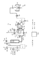
先ず図1を用いてレジスト塗布装置の全体構成について簡単に述べると、レジスト塗布装置は、基板であるウエハWを水平に保持する基板保持部であるスピンチャック63を含むカップモジュール60と、スピンチャック63に保持されたウエハWの中心部に処理液であるレジストを供給するためのノズル61と、このノズル61にレジストを供給する処理液供給装置であるレジスト供給装置10を備えている。
First, the overall configuration of the resist coating apparatus will be briefly described with reference to FIG. 1. The resist coating apparatus includes a cup module 60 including a
前記カップモジュール60は、スピンチャック63を囲むように設けられ、ウエハWから振り切られたレジストを受けるためのカップ体62を備え、カップ体62の下部には、吸引排気路が接続されると共にドレーンを排出できるようにドレーン機構が構成されている。カップ体62は、ミストの舞い上がりを防止するように内カップ、外カップなどが組み合わされて構成されているが、ここでは省略する。
The cup module 60 is provided so as to surround the
前記レジスト供給装置10は、複数の配管からなる配管系に複数の機構が組み合わされて構成されている。レジストの流れの上流側から説明すると、レジストを貯留する密閉型のボトル12を備え、ボトル12の上部には2本の配管210、212が接続され、一方の配管212はバルブ33を介し、リキッドエンドタンク13の上部のポートを介してリキッドエンドタンク13の底部へと延伸され、他方の配管210はバルブ32の一端へと接続される。バルブ32の他端には別の配管211が接続され、当該配管211は延伸された後2本の配管213、22に分岐し、一方の配管213はバルブ31を介し加圧用ガスの供給源、この実施形態ではN2ガス供給源11に接続される。他方の配管22はバルブ30を介して外部へ開放されていて、従ってこの配管22は排気管として構成されている。
The
前記リキッドエンドタンク13は、レジストをウエハWへと安定供給するために設けられ、図示しない液面センサが複数取り付けられ、液量の管理が行われている。リキッドエンドタンク13の上部には、ボトル12からリキッドエンドタンク13内部へと延伸されている前記配管212の他に、リキッドエンドタンク13内部からのドレーン管23が接続されており、当該ドレーン管23にはバルブ34が介設されている。一方リキッドエンドタンク13の底部ポートには下流側へとレジストを供給する配管213が接続されている。配管213は2本の配管214、215に分岐し、一方の配管214はバルブ35を介してフィルタ部14の上流側に接続され、他方の配管215はバルブ36を介してトラップ15の底部ポートに接続されている。
The
前記フィルタ部14は例えば図2(a)に示すように、処理液、この実施形態ではレジストをろ過するろ過部72とその支持部材、例えば容器本体71、区画部材74、プレート75などからなり、ろ過部材としては例えば中空糸膜などから構成される。図2においてレジストは供給口501を介してフィルタ部14内部へと流入し、第1の通流室51を経由してろ過部72でろ過され、第2の通流室51を経由して流出口502から流出する。ろ過部72と2つの通流室51及び52との間は通流口76aが設けられたプレート76で隔てられており、ろ過部72は例えば図2(b)に示すように中空の円筒形をしている。また、フィルタ部14の上流側にはドレーン用の流路78が設けられている。
For example, as shown in FIG. 2A, the
図1に戻り説明を続ける。フィルタ部14の下流側には配管216が接続され、この配管216の他端はトラップ15の上部壁面に接続されている。当該配管216には液中パーティクルカウンタ27が取り付けられている。トラップ15は、フィルタ部14から吐出された気泡及び異物の混入した処理液を貯留し、後述するドレーン管21へと排出することによりウエハWへの気泡や異物の吐出を防ぐために設けられている。
Returning to FIG. A
フィルタ部14の上流部及びトラップ15の上部のポートには、夫々配管217、218が接続され、夫々バルブ37及び38を介して、ドレーン管21に共通に接続される。また、トラップ15からは、側面下部と側面上部に設けられた2つのポートに夫々配管219、220が接続され、側面下部からの配管219はバルブ39を介して、側面上部からの配管220はバルブ40を介して、双方共にポンプ部16の上流側に接続されている。
前記ポンプ部16としては、ポンプ外部からの吸引加圧を反映する構造を有するポンプ機構が用いられる。例としてはダイアフラムポンプなどが挙げられる。そしてポンプ部16の下流側にはノズル61へと向かう配管24が接続され、ポンプ部16とノズル61との間にはバルブ41、電空エアオペレートバルブ42が介在している。ノズル61へのレジストの吐出は電空エアオペレートバルブ42の開閉によってもコントロールされる。
なお、図1等では、ポンプ部16について、図3の上段で表されるように1つの流入ポートと2つの流出ポートがあるように記載されているが、この描写は便宜的なものである。実際には図3の下段で表されるようにポンプ部16の流出ポートは1つであり、ポンプ部16への加圧及び吸引動作と併せて、バルブ39、40との協働作業によりポンプ部16は動作している。
As the
In FIG. 1 and the like, the
上述してきたレジスト塗布装置は制御部100により制御される。制御部100はCPU、メインメモリ及びバスなどからなり、各部位の制御を実行して所定の処理を行うように命令(各ステップ)が組まれているプログラムにより制御が行われる。このプログラムは、コンピュータ記憶媒体、例えばフレキシブルディスク、コンパクトディスク、ハードディスク、MO(光磁気ディスク)などの記憶部に格納されてメインメモリにインストールされる。ここでメインメモリにインストールされるプログラムには、スピンチャック63、ノズル61、N2ガス供給源11、ボトル12、フィルタ部14などを制御するためのプログラムも含まれており、CPUに読み込まれた上、前記各部が制御されるようになっている。
The resist coating apparatus described above is controlled by the
続いて、レジスト供給装置10におけるフィルタウェッティングの手順の一形態について述べていく。
先ず、フィルタ取付の前に、予めレジスト供給装置10からレジストを排出し、バルブ32を閉成した上、バルブ30及び31を開成する。そして排気管22からN2ガスを排気しながら、N2ガス供給源11からのN2ガス圧を例えば5kPaとなるように調節する。5kPaに圧力を設定する理由は、後述のようにフィルタ部14を新規なものに交換した後、系内にレジストを投入することによりフィルタ部14内における発泡を防止し、細かな溝へのレジスト浸透効果を高めるためである。なおガス圧の調整は、先ずバルブ31を閉成しN2ガスの供給を遮断し、バルブ33、35、38、39、41及び電空エアオペレートバルブ42を開成する。そしてトラップ15からのドレーン管21を通じた排気及びノズル61からの排気を行い、N2ガス圧を0にした後に、上述したN2ガス供給源11からのN2ガス圧の調整を行った上で、N2ガスを供給し系内への加圧を行う。
Subsequently, an example of a procedure of filter wetting in the resist
First, before attaching the filter, the resist is discharged from the resist
そして上述のようにN2ガス圧を調整した後に、フィルタ部14を新規取付、あるいは新規のフィルタ部に交換する。しかる後にバルブ30及びバルブ34を閉成し、バルブ31を開成した状態においてバルブ32及び33を開成し、N2ガス供給源11からのN2ガス圧によりボトル12からリキッドエンドタンク13にレジストを送出する。レジストのリキッドエンドタンク13への注入はレジストが一定量リキッドエンドタンク13に貯留されるまで行われる。
Then after adjusting the N 2 gas pressure as described above to replace the
次にリキッドエンドタンク13からフィルタ部14へレジストを注入する。この際にはバルブ35及びバルブ37を開成し、バルブ36及び38〜41を閉成することによりレジストの注入が行われる。当該レジストの注入は、液中パーティクルカウンタ27による気泡のモニタ、及びフィルタ部14内からドレーン管21へ排出されるレジストに対する目視による監視と共に行われ、目視により認識できる大きさの気泡が確認できなくなるまでレジストがフィルタ部14へと注入される。
Next, a resist is injected from the
次にフィルタ部14からトラップ15へレジストを注入する。この際にはバルブ35を開成したままバルブ37を閉成し、代わってバルブ38を開成することによりレジスト注入が行われる。当該レジストの注入は、液中パーティクルカウンタ27による気泡のモニタ、及びトラップ15内からドレーン管21へ排出されるレジストに対する目視による監視と共に行われ、目視により認識できる大きさの気泡及び異物が確認できなくなるまでレジストがトラップ15へと注入される。そして、系内を常圧に調整し、全てのバルブを閉成した上、系全体を例えば約15分放置し、フィルタ部14を処理液内に浸漬する。
Next, a resist is injected from the
しかる後に、N2ガス供給源11からのN2ガス圧を例えば50kPaとなるように調節し、バルブ31、32、33、35及び37を開成し、フィルタ部14内にレジストを圧送する。このステップにより、レジストがボトル12からリキッドエンドタンク13を経由してフィルタ部14へと圧送され、上述した工程内においてフィルタ部14内からレジスト中へ放出された気泡が、レジストと共にドレーン管21から排出される。当該レジストの圧送は、液中パーティクルカウンタ27による気泡のモニタ、及びフィルタ部14内からドレーン管21へ排出されるレジストに対する目視による監視と共に行われ、目視により認識できる大きさの気泡が確認できなくなるまで続けられる。
Thereafter, the N 2 gas pressure from the N 2
次にトラップ15内へレジストを圧送する。N2ガス圧を例えば50kPaに維持し、バルブ35を開成したままバルブ37を閉成し、代わってバルブ38を開成することにより、レジストがボトル12からリキッドエンドタンク13及びフィルタ部14を経由してトラップ15内へと圧送される。このステップにより、フィルタ部14内およびトラップ15内の異物及び気泡がドレーン管21から排出される。当該レジストの圧送は、液中パーティクルカウンタ27による気泡のモニタ、及びトラップ15内からドレーン管21へ排出されるレジストに対する目視による監視と共に行われ、目視により認識できる大きさの気泡及び異物が確認できなくなるまで続けられる。
Next, the resist is pumped into the
当該レジスト圧送工程において、レジスト圧送の初期の段階において、フィルタ部14に上流側から加わる圧力は大気圧以上の圧力(以下「正圧」と呼ぶ)とし、大気圧以下の圧力(以下「負圧」と呼ぶ)とならないようにしている。この工程の目的は、目視できるサイズの気泡及び異物をフィルタ部14及びトラップ15から除去することにある。後述する負圧ろ過工程は、フィルタ部14内部に残留する気泡核の成長を目的としており、当該負圧ろ過工程においてはポンプ吸引によってある程度の気泡がフィルタ部14から離脱するが、ほとんどの気泡は依然としてフィルタ部14内に残留する。一方、正圧ろ過によれば目視できるサイズの気泡及び異物をその圧力によってフィルタ部14内から排出することができるため、この段階で正圧ろ過を行っている。
In the resist pumping step, in the initial stage of resist pumping, the pressure applied to the
以上の手順により、フィルタ部14及びトラップ15内に残存していた、目視により認識できる気泡及び異物を除去した後、フィルタ部14の微細な気泡を除去する工程へと移る。この工程は複数のステップが複数回にわたり繰り返されることから、便宜上各ステップに符号を振った上、説明する。
After removing the bubbles and foreign matters remaining in the
<ステップa>
まずフィルタ部14に対し加圧によるろ過、この例では正圧によるろ過を行う。即ちフィルタ部14の上流側を加圧して下流側より高い圧力とし、その圧力差を、ウエハWに対してレジストを供給する通常運転時における圧力差よりも大きい状態とする。
具体的に手順を述べると、N2ガス圧を例えば50kPaに維持し、バルブ35を開成したままバルブ37を閉成し、バルブ38を開成し、リキッドエンドタンク13からフィルタ部14を通じてトラップ15内にレジストを圧送することによりレジストろ過を行い、ろ過したレジストは例えばドレーン管21から排出する。当該ステップにおいて、フィルタ部14におけるレジストろ過量は例えば40mL、ろ過時間は例えば30秒である。
このステップaにおけるレジストの流れを図4に示す。
<Step a>
First, filtration by pressurization is performed on the
Specifically, the N 2 gas pressure is maintained at, for example, 50 kPa, the
FIG. 4 shows the resist flow in step a.
<ステップb>
次に、フィルタ部14の下流側を減圧することによるろ過を行う。この例ではフィルタ部14に対する負圧によるろ過を行う。
概略的に手順を述べると、ポンプ16による吸引動作による工程(b−1)と、ポンプ16による圧縮動作による工程(b−2)の2工程からなる。以下、順を追って説明する。
<Step b>
Next, filtration is performed by depressurizing the downstream side of the
The procedure is roughly described. The process includes two steps: a step (b-1) by a suction operation by the
先ず工程(b−1)について説明する。図5に示すようにバルブ37、38を閉成し、バルブ39を開成する。続いてポンプ16内を吸引することによって、フィルタ部14内にレジストを通液させる。すると、フィルタ部14内で負圧ろ過の作用が生じ、フィルタ部14内に残留している微小な気泡核が成長あるいは膨張する。この負圧ろ過による気泡成長については、微細気泡の除去のメカニズムの一部として後述する。そして成長あるいは膨張した気泡の一部はフィルタ下流に流出する。当該工程において、フィルタ部14におけるレジストろ過量は例えば60mL、ろ過速度は例えば0.5mL/secである。
続いて工程(b−2)について説明する。図6に示すようにバルブ31を閉成し、系内へのN2ガス供給を停止する。続いて、バルブ30、33、34、36及び40を開成し、バルブ35を閉成し、ポンプ部16内を加圧することによりレジストを加圧し、バルブ40、トラップ15、バルブ36、リキッドエンドタンク13の経路を上流側に逆送する。これにより、上述のポンプ吸引動作により流出した気泡が、リキッドエンドタンク13とトラップ15との間に移動する。当該工程において、ポンプ部16からのレジスト圧送量は例えば0.5mLである。
First, the step (b-1) will be described. As shown in FIG. 5, the
Then, a process (b-2) is demonstrated. As shown in FIG. 6, the
<ステップc>
続いて、ステップbにより流出した気泡を系外へ排出するステップに移る。
具体的に手順を述べると、再びバルブ30を閉成し、バルブ31及び32を開成し、系内のN2ガス圧を例えば50kPaとする。バルブ35及び37を開成し、バルブ36、38及び40を閉成する。そしてリキッドエンドタンク13からフィルタ部14へのレジスト圧送を行い、気泡を含んだレジストを、フィルタ部14内部からドレーン管21を経由して排出する。このレジスト排出の際にトラップ15を経由しない理由は、気泡を含んだレジストがトラップ15を経由することによって、フィルタ14の2次側へ気泡が再付着することを防止するためである。
<Step c>
Subsequently, the process proceeds to a step of discharging the bubbles that have flowed out in step b to the outside of the system.
Specifically, the
そして上述してきたステップa、ステップb及びステップcを、この順番によって1サイクルとし、このサイクルを例えば10回繰り返す。なお、ステップbにおいて、フィルタ部14から気泡が流出しなかった場合は、もはやステップcを行う必要はなく、後述するステップa及びステップbの繰り返し工程に移行してもよい。
当該サイクルの繰り返しにおいて、ステップbにより負圧ろ過を行い気泡が成長した後に、ステップaに戻り正圧ろ過を行う。すると、気泡に対して圧壊という作用が起こり気泡が極微小な気泡の集合へと変化する、あるいは気泡がレジスト中に溶解するなど、気泡に対する変化が発生する。これらの変化により、ステップa及びcにてフィルタ部14内から気泡が排出されやすくなる。気泡に起こる当該変化については、微細気泡の除去のメカニズムの一部として後述する。
Then, step a, step b and step c described above are defined as one cycle according to this order, and this cycle is repeated, for example, 10 times. In step b, when bubbles do not flow out from the
In repetition of the cycle, after negative pressure filtration is performed in step b and bubbles are grown, the process returns to step a and positive pressure filtration is performed. Then, an action of crushing the bubble occurs, and the bubble is changed to a collection of extremely fine bubbles, or a change to the bubble occurs, for example, the bubble is dissolved in the resist. Due to these changes, bubbles are easily discharged from the
上述の10回のサイクルの繰り返し工程が終了した後、さらにステップa及びステップbをこの順番によって20回繰り返し、当該工程により、フィルタ部14全体の微細部の気泡を除去し、結果的にレジストをフィルタ部14の微細部まで行き渡らせる。
After the repetition of the 10 cycles described above, step a and step b are further repeated 20 times in this order, and in this process, fine bubbles in the
なお、ステップa、b、cを1サイクルとする代わりに、ステップb、a、cを1サイクルとして例えば同様に10回繰り返すようにしてもよい。また、ステップa、bを上述のように例えば20回繰り返す工程は、ステップb、aの順番で20回繰り返すようにしてもよい。 Instead of setting steps a, b, and c as one cycle, steps b, a, and c may be set as one cycle, for example, and may be repeated 10 times in the same manner. Further, the step of repeating steps a and b, for example, 20 times as described above may be repeated 20 times in the order of steps b and a.
こうしてフィルタウェッティング工程が終了したところで、処理液供給装置によるプロセスを行う。例えばポンプ部による加圧により、レジストをウエハW上に例えば0.1mLずつ吐出し、スピンコーティング法によりレジストの塗布を行う。 When the filter wetting process is completed in this way, a process by the processing liquid supply device is performed. For example, by applying pressure by a pump unit, for example, 0.1 mL of resist is discharged onto the wafer W, and the resist is applied by spin coating.
ここで、上述したフィルタ部14からの微細気泡の除去のメカニズムについて詳説する。
上述の実施形態において,減圧ろ過(負圧ろ過)と加圧ろ過(正圧ろ過)とを繰り返し行うことによって、次に述べるメカニズムで気泡がフィルタ部14の微細構造部分から離脱されるものと考えられている。
レジスト内に浸漬されたフィルタ部14内のフィルタには微細な気泡が多く存在している。Harveyの核モデルという理論によりこれらの微細な気泡は気泡核と呼ばれ、この理論では、以下のような気泡核の振る舞いが明らかになっている。
Here, the mechanism for removing the fine bubbles from the
In the above-described embodiment, it is considered that bubbles are separated from the fine structure portion of the
Many fine bubbles exist in the filter in the
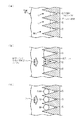
即ち、図7(a)のように円錐形の固体の溝Gの最奥部に微小な容積の空気(気泡核C)が含まれ、その上に液体が満たされているとき、気泡核Cの空気圧をPi、液体に溶存している空気の平衡圧をPeとすると、Pi>Peが成立するとき、気泡核Cの表面は液体中にせり出し(図7(b))、一定の場所までせり出すと、大部分が液体中に泡Bとなって放出される(図7(c))。この泡Bはフィルタ部14あるいはトラップ15からドレーン管21を経由して排出することができる(図8(d))。泡Bを放出した後も気泡核Cは溝Gの内部に残存するが、その体積は泡Bを放出する前よりも小さくなっている。
That is, when a minute volume of air (bubble nucleus C) is contained in the deepest part of the conical solid groove G as shown in FIG. If the air pressure P i, the equilibrium pressure of the air dissolved in the liquid and P e, when P i> P e is satisfied, the surface of the bubble nuclei C is pushed out into the liquid (FIG. 7 (b)), When protruding to a certain place, most of the liquid is released as bubbles B in the liquid (FIG. 7C). The bubbles B can be discharged from the
また、気泡について古くから知られているのが圧壊という現象である。圧壊とは、大きな気泡が崩壊して微細な気泡となる現象である。即ち、図9(a)のように溝Gの最奥部に存在する気泡核Cに負圧Peが掛かると(図9(b))、気泡核の圧力PiはPeより大きいため、気泡核Cは溝Gいっぱいまで膨張する。そして膨張した気泡核Cに対し大きな正圧Psを急激に加えることにより、気泡核Cは破壊される(図9(c))。破壊されたあとの気泡核Cは無数の微小な粒子様となり雲状になって広がり、フィルタ部14から離脱される。この一連の作用が圧壊と呼ばれる現象である。
Also, a phenomenon known as crushing has been known for a long time about bubbles. Crushing is a phenomenon in which large bubbles collapse and become fine bubbles. That is, when the negative pressure P e in the bubble nuclei C present in the deepest portion of the groove G as shown in FIG. 9 (a) is applied (FIG. 9 (b)), the pressure P i of the bubble nuclei for larger P e The bubble nucleus C expands to fill the groove G. Then, by rapidly applying a large positive pressure P s to the expanded bubble nucleus C, the bubble nucleus C is destroyed (FIG. 9C). The bubble nuclei C after being destroyed become innumerable microscopic particles like a cloud and spread from the
さらに、正圧ろ過と負圧ろ過の繰り返しにより気泡が大きくなる現象は、次のように説明できる。即ち、液体中に気泡核が存在する状態において、溶存気体の圧力を降下させるか、液体の温度を上昇させ、この液体を過飽和状態にすると、気泡核を基点にマイクロバブルと呼ばれる気泡が発生する。このマイクロバブルは、溶存気体を取り込むことにより成長する性質を持つ。故に、マイクロバブルが生成された時点において液体の圧力を低下させることにより、マイクロバブルは成長する。成長した大きなマイクロバブルは即ち気泡であるので容易に除去することができる。 Furthermore, the phenomenon that bubbles increase due to repetition of positive pressure filtration and negative pressure filtration can be explained as follows. That is, in a state where bubble nuclei exist in the liquid, when the pressure of the dissolved gas is lowered or the temperature of the liquid is raised and the liquid is supersaturated, bubbles called microbubbles are generated with the bubble nuclei as the base point. . These microbubbles have the property of growing by taking in dissolved gas. Therefore, by reducing the pressure of the liquid at the time when the microbubble is generated, the microbubble grows. Grown large microbubbles, that is, bubbles, can be easily removed.
またさらに、気泡核が処理液中に溶解する現象は、次のように説明できる。
即ち、液体内において半径Rの水蒸気核が形成されるとき、一定温度一定圧力下において以下の式が成り立つ。

That is, when a water vapor nucleus having a radius R is formed in the liquid, the following equation is established under a constant temperature and a constant pressure.
ここで、Gはギブスの自由エネルギー、R*は圧力と温度に応じて一意に決定される水蒸気核の半径である。半径がR*である水蒸気核の大きさを「基本サイズ」と呼ぶことにする。また、(1)の左辺は水蒸気核のポテンシャルに比例する。式(1)の左辺を縦軸に、R/R*を横軸に取ったグラフが図10である。 Here, G is Gibbs free energy, and R * is the radius of the water vapor nucleus uniquely determined according to pressure and temperature. The size of the water vapor nucleus whose radius is R * will be referred to as “basic size”. The left side of (1) is proportional to the potential of the water vapor nucleus. FIG. 10 is a graph in which the left side of Equation (1) is taken on the vertical axis and R / R * is taken on the horizontal axis.
ここで、水蒸気核は、液体と共存した平衡状態を保つために、ポテンシャルの低い状態へと変化し、その結果自らの半径Rを変化させる。図10のグラフではR/R*=1、つまりRが基本サイズのとき水蒸気核のポテンシャルが最も高い。
R/R*<1の時、つまり水蒸気核が基本サイズより小さいときは、水蒸気核はポテンシャルの低い状態に変化する結果、R/R*が0になるように変化する。R*は定数であり、よってRは0となるように変化し、結果として水蒸気核は消滅する。
一方R/R*>1の時、つまり水蒸気核が基本サイズより大きいときは、やはりポテンシャルの低い状態に変化する結果、R/R*は増大する。R*は定数であり、よってRは大きくなり、結果として水蒸気核は膨張する。
R/R*=1の時は、水蒸気核は上記のどちらかとなる。即ち消滅または膨張のどちらの結果ともなりうる。
よって最終的に水蒸気核は消滅、膨張若しくは破裂する。
Here, the water vapor nucleus changes to a low potential state in order to maintain an equilibrium state coexisting with the liquid, and as a result, changes its radius R. In the graph of FIG. 10, when R / R * = 1, that is, when R is the basic size, the potential of the water vapor nucleus is the highest.
When R / R * <1, that is, when the water vapor nucleus is smaller than the basic size, the water vapor nucleus changes to a low potential state, and as a result, R / R * changes to zero. R * is a constant, so that R changes to be 0, and as a result, the water vapor nucleus disappears.
On the other hand, when R / R * > 1, that is, when the water vapor nucleus is larger than the basic size, R / R * increases as a result of changing to a low potential state. R * is a constant, so R becomes large, and as a result, the water vapor nucleus expands.
When R / R * = 1, the water vapor nucleus is either of the above. That is, it can result in either extinction or expansion.
Thus, eventually the water vapor nuclei disappear, expand or rupture.
上述してきた理由により、負圧ろ過及び正圧ろ過の繰り返しによりフィルタ部14内部の気泡は膨張、破裂、消滅などの挙動をとることから、本発明ではこれらの作用を利用してフィルタ部14内部から気泡を除去している。
For the reasons described above, bubbles in the
一方、作用の説明で前述したフィルタ部14及びトラップ15内に処理液を注入した後、処理液をフィルタ部14内に圧送する前に、系全体を放置し、フィルタ部14を処理液内に浸漬するステップの目的は、毛細管現象により処理液をフィルタ部14内の細部にまで浸透させることにある。
On the other hand, after injecting the processing liquid into the
この処理液のフィルタ内部への浸透について概説すると、毛細管現象による細部への液浸透度と時間との関係は、Washburn式と呼ばれる次式により表される。
(2)において、zは浸透深度、θEは静的接触角、γは液体の表面張力、Rは毛細管の半径、ηは液体の粘性係数、tは時間である。よってzは時間の1/2乗に比例する。このzと時間tとの関係をグラフに表したものが図11である。グラフから、フィルタへの処理液の浸透は、浸透初期ほど単位時間当たりに自然浸透する深度が大きいことがわかる。即ち毛細管現象により細部に液を浸透させる当該工程を行うのであれば、フィルタウェッティング工程の初期に行う方が時間的効率がよい、といえる。 In (2), z is the penetration depth, θ E is the static contact angle, γ is the surface tension of the liquid, R is the radius of the capillary, η is the viscosity coefficient of the liquid, and t is time. Therefore, z is proportional to the 1/2 power of time. FIG. 11 is a graph showing the relationship between z and time t. From the graph, it can be seen that the penetration of the treatment liquid into the filter has a greater depth of natural penetration per unit time as the initial penetration. In other words, if the process for infiltrating the liquid in detail by capillary action is performed, it can be said that it is more time efficient to perform it at the beginning of the filter wetting process.
以上において、本発明に係る液処理装置の実施例として、レジスト供給装置10について説明したが、実際の液処理装置としては、勿論取り扱う処理液はレジストに限るものではなく、背景技術に記載した、他の薬液、例えば絶縁膜形成用薬液に対する処理にも応用が可能である。
In the above, the resist
本発明を評価するための評価試験及び本発明の効果を確認するための比較試験について述べる。 An evaluation test for evaluating the present invention and a comparative test for confirming the effect of the present invention will be described.
A.フィルタ通液量と気泡量との相関に関する評価試験
(評価試験A−1)
上述した実施形態と同様の構成の液処理装置を用いて、フィルタ取付後薬液を装置内に導入し、直後に薬液の正圧ろ過と負圧ろ過を繰り返し、フィルタウェッティング工程を行った場合のフィルタ通液量と薬液1mLあたりの100nm以上の大きさの気泡数の相関を調べた。
(評価試験A−2)
評価試験A−1と同じ装置を用い、フィルタ取付後薬液を装置内に導入し、フィルタを薬液中に15分浸漬し、それ以外は評価試験A−1と同じ条件により薬液の正圧ろ過と負圧ろ過を繰り返し、フィルタウェッティング工程を行った場合のフィルタ通液量と薬液1mLあたりの100nm以上の大きさの気泡数の相関を調べた。
(比較試験A−1)
評価試験A−1と同じ装置を用い、薬液の正圧ろ過のみによりフィルタウェッティング工程を行った場合のフィルタ通液量と薬液1mLあたりの100nm以上の大きさの気泡数の相関を調べた。
(比較試験A−2)
評価試験A−1と同じ装置を用い、薬液の負圧ろ過のみによりフィルタウェッティング工程を行った場合のフィルタ通液量と薬液1mLあたりの100nm以上の大きさの気泡数の相関を調べた。
A. Evaluation test on correlation between filter flow rate and bubble volume (Evaluation Test A-1)
Using the liquid processing apparatus having the same configuration as the embodiment described above, the chemical liquid after the filter is installed is introduced into the apparatus, and immediately after the positive pressure filtration and the negative pressure filtration of the chemical liquid are repeated, the filter wetting process is performed. The correlation between the flow rate of the filter and the number of bubbles having a size of 100 nm or more per 1 mL of the chemical solution was examined.
(Evaluation Test A-2)
Using the same device as the evaluation test A-1, the chemical solution was introduced into the device after the filter was attached, and the filter was immersed in the chemical solution for 15 minutes. Negative pressure filtration was repeated, and the correlation between the filter flow rate when the filter wetting process was performed and the number of bubbles having a size of 100 nm or more per 1 mL of the chemical solution was examined.
(Comparative test A-1)
Using the same apparatus as in evaluation test A-1, the correlation between the amount of filtered liquid and the number of bubbles with a size of 100 nm or more per 1 mL of the chemical solution was examined when the filter wetting process was performed only by positive pressure filtration of the chemical solution.
(Comparative test A-2)
Using the same apparatus as in evaluation test A-1, the correlation between the amount of filtered liquid and the number of bubbles with a size of 100 nm or more per mL of the chemical solution was examined when the filter wetting process was performed only by negative pressure filtration of the chemical solution.
なお、各実験におけるN2ガス圧、ろ過レートなどの条件は以下の通りである。
・使用薬液:OK73シンナー(登録商標・東京応化社製)
・N2ガス圧(正圧ろ過時):50kPa
・負圧ろ過時ろ過レート:0.5mL/sec
・評価試験A−1、A−2における正圧ろ過時1回当たりのフィルタ通液量:
40mL
・評価試験A−1、A−2における負圧ろ過時1回当たりのフィルタ通液量:
60mL
結果を図12に示す。グラフの実線が評価試験A−1、破線が評価試験A−2、点線が比較試験A−1、一点鎖線が比較試験A−2の結果を示したものである。横軸は通液量、縦軸は1mLあたりの100nm以上の大きさの気泡数を対数に取ったものである。
グラフに表した結果より、まず比較試験A−2の結果から、負圧ろ過のみではフィルタから気泡が十分に除去されないことが明らかである。また、他の試験例について、1mLあたりの気泡数が0.1個となった段階を安定状態とすると、評価試験A−1及び比較試験A−1では安定状態になるまで通液量が約3500mL必要であった。しかしこの2つの試験を比較すると、比較試験A−1は通液中において時折急激な気泡数の上昇がみられるのに対し、評価試験A−1では通液中に気泡数が上昇することがほとんどない。この点により評価試験A−1の結果は比較試験A−1の結果より優れているといえる。
Incidentally, N 2 gas pressure in each experiment, the conditions such as filtration rate is as follows.
-Chemical solution used: OK73 thinner (registered trademark, manufactured by Tokyo Ohka Co., Ltd.)
・ N 2 gas pressure (at the time of positive pressure filtration): 50 kPa
-Filtration rate during negative pressure filtration: 0.5 mL / sec
-Filter flow rate per one time during positive pressure filtration in evaluation tests A-1 and A-2:
40 mL
-Filter flow rate per one time during negative pressure filtration in evaluation tests A-1 and A-2:
60 mL
The results are shown in FIG. The solid line in the graph shows the result of evaluation test A-1, the broken line shows the result of evaluation test A-2, the dotted line shows the result of comparative test A-1, and the alternate long and short dash line shows the result of comparative test A-2. The horizontal axis is the amount of liquid flow, and the vertical axis is the logarithm of the number of bubbles of 100 nm or more per mL.
From the results shown in the graph, it is clear from the results of the comparative test A-2 that bubbles are not sufficiently removed from the filter only by negative pressure filtration. In addition, regarding other test examples, assuming that the stage where the number of bubbles per mL becomes 0.1 is a stable state, in the evaluation test A-1 and the comparative test A-1, the amount of liquid flow is about to reach a stable state. 3500 mL was required. However, when comparing these two tests, the comparative test A-1 sometimes shows an abrupt increase in the number of bubbles during the passage, whereas the evaluation test A-1 shows an increase in the number of bubbles during the passage. rare. From this point, it can be said that the result of the evaluation test A-1 is superior to the result of the comparative test A-1.
またさらに、評価試験A−2では、安定状態になるまでの通液量が約2500mLと、他の3つの試験に比して明らかな減少がみられ、通液中に大幅な気泡の増加も観察されなかった。
これらの4つの試験結果から、フィルタウェッティング工程においてはフィルタ交換後にフィルタを薬液中に浸漬した上放置し、その後正圧ろ過と負圧ろ過を交互に繰り返す工程、すなわち評価試験A−2の工程がもっとも薬液消費量の低減につながるといえる。
Furthermore, in the evaluation test A-2, the flow rate until the stable state is reached is about 2500 mL, which is a clear decrease compared to the other three tests, and there is also a significant increase in bubbles during the flow. Not observed.
From these four test results, in the filter wetting process, after replacing the filter, the filter is immersed in a chemical solution and allowed to stand, and thereafter positive pressure filtration and negative pressure filtration are alternately repeated, that is, the process of evaluation test A-2 However, it can be said that this leads to the reduction of chemical consumption.
B.フィルタウェッティング工程後の連続負圧ろ過と気泡量との相関に関する評価試験
(評価試験B−1)
評価試験A−1と同じ装置により同じ手順を行い、薬液1mLあたりの気泡数が0.1個となった後、0.5mL/secにより6秒間の負圧ろ過を100回繰り返す試験を4回行い、薬液1mLあたりの100nm以上の大きさの気泡量の分布を調べた。
(評価試験B−2)
評価試験A−2と同じ装置により同じ手順を行い、薬液1mLあたりの気泡数が0.1個となった後、0.5mL/secにより6秒間の負圧ろ過を100回繰り返す試験を4回行い、薬液1mLあたりの100nm以上の大きさの気泡量の分布を調べた。
(比較試験B−1)
比較試験A−1と同じ装置により同じ手順を行い、薬液1mLあたりの気泡数が0.1個となった後、0.5mL/secにより6秒間の負圧ろ過を100回繰り返す試験を4回行い、薬液1mLあたりの100nm以上の大きさの気泡量の分布を調べた。
B. Evaluation test on correlation between continuous negative pressure filtration after filter wetting process and amount of bubbles (Evaluation Test B-1)
The same procedure was performed with the same apparatus as in Evaluation Test A-1, and after the number of bubbles per mL of chemical solution reached 0.1, 4 tests were repeated 100 times for 6 seconds of negative pressure filtration at 0.5 mL / sec. The distribution of the amount of bubbles having a size of 100 nm or more per 1 mL of the chemical solution was examined.
(Evaluation Test B-2)
The same procedure was performed using the same apparatus as in Evaluation Test A-2, and after the number of bubbles per mL of chemical solution reached 0.1, four tests were repeated 100 times for 6 seconds of negative pressure filtration at 0.5 mL / sec. The distribution of the amount of bubbles having a size of 100 nm or more per 1 mL of the chemical solution was examined.
(Comparative test B-1)
The same procedure was performed with the same apparatus as Comparative Test A-1, and the number of bubbles per mL of the chemical solution was 0.1, and then the test was repeated 100 times for 6 seconds of negative pressure filtration at 0.5 mL / sec. The distribution of the amount of bubbles having a size of 100 nm or more per 1 mL of the chemical solution was examined.
結果を図13に示す。比較試験B−1においては、気泡量が1mLあたり約2個前後の部分に主な分布がみられるのに対し、評価試験B−1及びB−2では分布が約0.5個付近の部分に分布が見られ、比較試験に比べ気泡量の減少がみられる。また、観測された気泡の数については、統計学的検定の結果、有意に(p<0.05)評価試験と比較試験との間で差が認められた。
この評価試験から、フィルタ交換時におけるフィルタウェッティング工程においてフィルタに対し正圧ろ過と負圧ろ過を繰り返す手法において、フィルタウェッティング工程後、負圧ろ過のみを繰り返しても薬液中の気泡量が増加しないことが示された。結果、従来の正圧ろ過のみによるフィルタウェッティング工程よりも改善された効果が検証できた。
The results are shown in FIG. In comparative test B-1, the main distribution is observed in the portion where the amount of bubbles is about 2 per mL, whereas in evaluation tests B-1 and B-2, the portion where the distribution is around 0.5. Distribution is seen, and the amount of bubbles is reduced compared to the comparative test. As for the number of bubbles observed, as a result of statistical test, a significant difference (p <0.05) was observed between the evaluation test and the comparative test.
From this evaluation test, in the method of repeating positive pressure filtration and negative pressure filtration on the filter in the filter wetting process at the time of filter replacement, the amount of bubbles in the chemical solution increases even if only negative pressure filtration is repeated after the filter wetting process. It was shown not to. As a result, it was possible to verify an improved effect over the conventional filter wetting process using only positive pressure filtration.
10 処理液供給装置
11 N2ガス供給源
12 薬液ボトル
14 フィルタ部
15 トラップ
16 ポンプ部
21 ドレーン管
31〜42 バルブ
60 カップモジュール
63 スピンチャック
W ウエハ
G 極細溝
C 気泡核
10 process
Claims (11)
前記フィルタ部の新規取り付け後または交換後に前記フィルタ部の上流側から下流側に処理液を満たす工程と、
次いで前記送液機構により前記フィルタ部の下流側の処理液を減圧して当該フィルタ部に処理液を通流させる減圧ろ過ステップと、処理液を前記フィルタ部の上流側から加圧して当該フィルタ部を通流させる加圧ろ過ステップと、を複数回繰り返す工程と、を含むことを特徴とする処理液供給装置の運転方法。 A flow path between the processing liquid supply source and the nozzle is provided with a filter part, a gas outlet in the processing liquid, and a liquid feeding mechanism in order from the upstream side. The liquid feeding mechanism processes the object to be processed through the nozzle. In a method of operating a processing liquid supply apparatus for supplying a liquid,
Filling the treatment liquid from the upstream side to the downstream side of the filter unit after the new attachment or replacement of the filter unit;
Next, a decompression filtration step of reducing the pressure of the processing liquid downstream of the filter unit by the liquid feeding mechanism and flowing the processing liquid through the filter unit, and pressurizing the processing liquid from the upstream side of the filter unit And a step of repeating the pressure filtration step of passing the fluid a plurality of times, and a method of operating the treatment liquid supply apparatus.
前記フィルタ部の新規取り付け後または交換後に、前記フィルタ部の上流側から下流側に処理液を満たす工程と、
次いで前記送液機構により前記フィルタ部の下流側の処理液を減圧して当該フィルタ部に処理液を通流させる減圧ろ過ステップと、処理液を前記フィルタ部の上流側から加圧して当該フィルタ部を通流させる加圧ろ過ステップと、を複数回繰り返す工程と、
を実施するための制御信号を出力する制御部を備えたことを特徴とする処理液供給装置。 A flow path between the processing liquid supply source and the nozzle is provided with a filter part, a gas outlet in the processing liquid, and a liquid feeding mechanism in order from the upstream side. The liquid feeding mechanism processes the object to be processed through the nozzle. In the processing liquid supply device for supplying the liquid,
After newly attaching or replacing the filter unit, filling the processing liquid from the upstream side to the downstream side of the filter unit;
Next, a decompression filtration step of reducing the pressure of the processing liquid downstream of the filter unit by the liquid feeding mechanism and flowing the processing liquid through the filter unit, and pressurizing the processing liquid from the upstream side of the filter unit A step of repeating a pressure filtration step of passing through a plurality of times;
A processing liquid supply apparatus comprising a control unit that outputs a control signal for performing the above.
前記制御部の制御信号により実施される前記減圧ろ過ステップは、前記フィルタ部の上流側のバルブを閉じた状態とし、前記バイパス路に、前記送液機構により処理液を前記他端側から一端側に通流させることにより、前記フィルタ部の下流側の処理液を減圧させることを特徴とする請求項7または8に記載の処理液供給装置。 A valve provided on the upstream side of the filter unit, the one end on the upstream side of the valve and the other end side is connected to the liquid feed mechanism is connected, and a bypass passage that bypasses the filter unit,
The vacuum filtration step performed by the control signal of the control unit closes the valve on the upstream side of the filter unit, and supplies the treatment liquid to the bypass path from the other end side to the one end side by the liquid feeding mechanism. The processing liquid supply apparatus according to claim 7, wherein the processing liquid on the downstream side of the filter unit is depressurized by flowing through the processing liquid.
前記コンピュータプログラムは、請求項1ないし6のいずれか一項に記載の処理液供給装置の運転方法を実施するためのものであることを特徴とする記憶媒体。 A storage medium in which a computer program used in an apparatus for performing a method of operating the processing liquid supply apparatus using the processing liquid supplied from the processing liquid supply source is recorded,
A storage medium characterized in that the computer program is for carrying out the operating method of the processing liquid supply apparatus according to any one of claims 1 to 6.
Priority Applications (6)
| Application Number | Priority Date | Filing Date | Title |
|---|---|---|---|
| JP2012173299A JP5910401B2 (en) | 2012-08-03 | 2012-08-03 | Method of operating processing liquid supply apparatus, processing liquid supply apparatus, and storage medium |
| TW102127452A TWI544971B (en) | 2012-08-03 | 2013-07-31 | Method of operating process liquid supply device,process liquid supply device,and storage medium |
| KR1020130091329A KR101788352B1 (en) | 2012-08-03 | 2013-08-01 | Process liquid supply apparatus operating method, process liquid supply apparatus and storage medium |
| US13/956,507 US9508574B2 (en) | 2012-08-03 | 2013-08-01 | Process liquid supply apparatus operating method, process liquid supply apparatus and non-transitory storage medium |
| CN201310334130.4A CN103567110B (en) | 2012-08-03 | 2013-08-02 | Handle the method for operation and processing liquid supplying device of liquid supplying device |
| US15/336,856 US9576829B1 (en) | 2012-08-03 | 2016-10-28 | Process liquid supply apparatus operating method, process liquid supply apparatus and non-transitory storage medium |
Applications Claiming Priority (1)
| Application Number | Priority Date | Filing Date | Title |
|---|---|---|---|
| JP2012173299A JP5910401B2 (en) | 2012-08-03 | 2012-08-03 | Method of operating processing liquid supply apparatus, processing liquid supply apparatus, and storage medium |
Publications (3)
| Publication Number | Publication Date |
|---|---|
| JP2014033111A JP2014033111A (en) | 2014-02-20 |
| JP2014033111A5 JP2014033111A5 (en) | 2014-10-16 |
| JP5910401B2 true JP5910401B2 (en) | 2016-04-27 |
Family
ID=50024448
Family Applications (1)
| Application Number | Title | Priority Date | Filing Date |
|---|---|---|---|
| JP2012173299A Active JP5910401B2 (en) | 2012-08-03 | 2012-08-03 | Method of operating processing liquid supply apparatus, processing liquid supply apparatus, and storage medium |
Country Status (5)
| Country | Link |
|---|---|
| US (2) | US9508574B2 (en) |
| JP (1) | JP5910401B2 (en) |
| KR (1) | KR101788352B1 (en) |
| CN (1) | CN103567110B (en) |
| TW (1) | TWI544971B (en) |
Families Citing this family (21)
| Publication number | Priority date | Publication date | Assignee | Title |
|---|---|---|---|---|
| JP6010457B2 (en) * | 2012-12-28 | 2016-10-19 | 東京エレクトロン株式会社 | Liquid processing apparatus and chemical recovery method |
| CN104979236B (en) * | 2014-04-11 | 2017-09-26 | 沈阳芯源微电子设备有限公司 | A kind of chemical liquid supplying device and its supply method |
| US20170045042A1 (en) * | 2014-04-30 | 2017-02-16 | Anthony HURTER | Supercritical water used fuel oil purification apparatus and process |
| WO2015175790A1 (en) | 2014-05-15 | 2015-11-19 | Tokyo Electron Limited | Method and apparatus for increased recirculation and filtration in a photoresist dispense system |
| KR102320180B1 (en) * | 2014-05-30 | 2021-11-03 | 세메스 주식회사 | filter unit and having the same Apparatus for supplying chemical |
| JP6330624B2 (en) * | 2014-11-04 | 2018-05-30 | 東京エレクトロン株式会社 | Processing liquid supply device and cleaning method of processing liquid supply device |
| JP6222118B2 (en) * | 2015-01-09 | 2017-11-01 | 東京エレクトロン株式会社 | TREATMENT LIQUID FILTER, CHEMICAL LIQUID SUPPLY DEVICE, TREATMENT LIQUID FILTERING METHOD, AND STORAGE MEDIUM |
| JP6319117B2 (en) * | 2015-01-26 | 2018-05-09 | 東京エレクトロン株式会社 | Treatment liquid supply apparatus, treatment liquid supply method, and storage medium |
| US10121685B2 (en) * | 2015-03-31 | 2018-11-06 | Tokyo Electron Limited | Treatment solution supply method, non-transitory computer-readable storage medium, and treatment solution supply apparatus |
| JP6425669B2 (en) * | 2015-03-31 | 2018-11-21 | 東京エレクトロン株式会社 | Treatment liquid supply method, readable computer storage medium, and treatment liquid supply device |
| JP5991403B2 (en) * | 2015-04-21 | 2016-09-14 | 東京エレクトロン株式会社 | Filter-wetting method, filter-wetting device, and storage medium |
| KR20170010454A (en) | 2015-06-30 | 2017-02-01 | 세메스 주식회사 | Bubble removing unit and Apparatus for treating a substrate with the unit |
| CN109564861B (en) * | 2016-07-29 | 2019-12-13 | 松下知识产权经营株式会社 | microbubble cleaning device and microbubble cleaning method |
| JP6252926B1 (en) * | 2016-07-29 | 2017-12-27 | パナソニックIpマネジメント株式会社 | Fine bubble cleaning apparatus and fine bubble cleaning method |
| JP6803701B2 (en) * | 2016-08-23 | 2020-12-23 | 東京エレクトロン株式会社 | Substrate processing equipment, substrate processing method and recording medium |
| JP6966260B2 (en) * | 2017-08-30 | 2021-11-10 | 株式会社Screenホールディングス | Pump equipment, processing liquid supply equipment and substrate processing equipment |
| US11273396B2 (en) * | 2018-08-31 | 2022-03-15 | Taiwan Semiconductor Manufacturing Company, Ltd. | Liquid supply system with improved bubble venting capacity |
| KR20200126552A (en) * | 2019-04-30 | 2020-11-09 | 삼성전자주식회사 | Resist Filtering System Having Multi Filters and an Apparatus Having the Resist Filtering System |
| CN112999701B (en) * | 2019-12-20 | 2023-08-11 | 台湾积体电路制造股份有限公司 | Apparatus for removing bubbles from viscous fluids |
| KR102548294B1 (en) * | 2020-04-24 | 2023-06-28 | 세메스 주식회사 | Unit for supplying liquid, apparatus for treating substrate and method for treating substrate |
| US20230128280A1 (en) * | 2020-10-23 | 2023-04-27 | Lg Energy Solution, Ltd. | Electrode Insulation Liquid Supply Apparatus and Electrode Insulation Liquid Supply Method |
Family Cites Families (14)
| Publication number | Priority date | Publication date | Assignee | Title |
|---|---|---|---|---|
| JPH0237228B2 (en) * | 1982-08-06 | 1990-08-23 | Mitsubishi Electric Corp | GOSEIJUSHINOGANSHINHOHO |
| JPH04196517A (en) | 1990-11-28 | 1992-07-16 | Tokyo Electron Ltd | Liquid treating method |
| JP3301213B2 (en) * | 1994-04-13 | 2002-07-15 | ミツミ電機株式会社 | How to determine chemical replacement time |
| JP4011210B2 (en) * | 1998-10-13 | 2007-11-21 | 株式会社コガネイ | Chemical supply method and chemical supply device |
| US6418942B1 (en) * | 2000-03-10 | 2002-07-16 | Donald Gray | Solvent and aqueous decompression processing system |
| JP3706294B2 (en) * | 2000-03-27 | 2005-10-12 | 東京エレクトロン株式会社 | Treatment liquid supply apparatus and treatment liquid supply method |
| JP4205318B2 (en) * | 2001-05-23 | 2009-01-07 | 富士フイルム株式会社 | Filter medium processing method in liquid flow path |
| JP3947398B2 (en) * | 2001-12-28 | 2007-07-18 | 株式会社コガネイ | Chemical solution supply apparatus and chemical solution supply method |
| EP1874446A1 (en) * | 2005-04-25 | 2008-01-09 | Entegris, Inc. | Method and apparatus for treating fluids to reduce microbubbles |
| KR100772844B1 (en) * | 2005-11-30 | 2007-11-02 | 삼성전자주식회사 | Apparatus for dispensing photosensitive solution in semiconductor device fabrication equipment |
| US7967978B2 (en) * | 2006-12-11 | 2011-06-28 | International Business Machines Corporation | Method and apparatus for filter conditioning |
| JP4683008B2 (en) * | 2007-04-04 | 2011-05-11 | 株式会社デンソー | Method for forming film in nozzle hole of fuel injection nozzle |
| JP4879253B2 (en) * | 2008-12-04 | 2012-02-22 | 東京エレクトロン株式会社 | Treatment liquid supply device |
| JP2011230367A (en) | 2010-04-27 | 2011-11-17 | Canon Inc | Liquid supply structure and liquid ejection head using that structure |
-
2012
- 2012-08-03 JP JP2012173299A patent/JP5910401B2/en active Active
-
2013
- 2013-07-31 TW TW102127452A patent/TWI544971B/en active
- 2013-08-01 US US13/956,507 patent/US9508574B2/en active Active
- 2013-08-01 KR KR1020130091329A patent/KR101788352B1/en not_active Application Discontinuation
- 2013-08-02 CN CN201310334130.4A patent/CN103567110B/en active Active
-
2016
- 2016-10-28 US US15/336,856 patent/US9576829B1/en active Active
Also Published As
| Publication number | Publication date |
|---|---|
| KR20140018130A (en) | 2014-02-12 |
| TW201420209A (en) | 2014-06-01 |
| CN103567110A (en) | 2014-02-12 |
| TWI544971B (en) | 2016-08-11 |
| US20170043287A1 (en) | 2017-02-16 |
| CN103567110B (en) | 2017-08-11 |
| US9576829B1 (en) | 2017-02-21 |
| JP2014033111A (en) | 2014-02-20 |
| KR101788352B1 (en) | 2017-10-19 |
| US9508574B2 (en) | 2016-11-29 |
| US20140034584A1 (en) | 2014-02-06 |
Similar Documents
| Publication | Publication Date | Title |
|---|---|---|
| JP5910401B2 (en) | Method of operating processing liquid supply apparatus, processing liquid supply apparatus, and storage medium | |
| US9975073B2 (en) | Processing liquid supply method, processing liquid supply apparatus and storage medium | |
| KR101262410B1 (en) | Method and apparatus for treating fluids to reduce microbubbles | |
| JP2010528833A (en) | Membrane module with pulsed airlift pump | |
| US20080236639A1 (en) | Substrate treating apparatus | |
| TWI491441B (en) | Gas-liquid mixed fluid generating device, gas-liquid mixed fluid generating method, processing device, and processing method | |
| KR20130132286A (en) | Ultrasonic cleaning method and ultrasonic cleaning apparatus | |
| JP5412135B2 (en) | Ozone water supply device | |
| JP2016189493A (en) | Liquid processing method, liquid processing device, storage medium | |
| JP6895818B2 (en) | Treatment liquid supply device and treatment liquid supply method | |
| JP2002346312A (en) | Filter medium treatment method in liquid feed flow channel | |
| US20240105469A1 (en) | Liquid supply system | |
| JPH11121422A (en) | Chemical supplying equipment | |
| JP2020136509A (en) | Filter wetting method and processing liquid supply device | |
| US20210245077A1 (en) | Vacuum Assisted Filtration | |
| JPH05228304A (en) | Filter device | |
| JP5991403B2 (en) | Filter-wetting method, filter-wetting device, and storage medium | |
| JP3817005B2 (en) | Asphalt extraction apparatus and asphalt extraction method for asphalt mixture | |
| JP3283190B2 (en) | Resist processing apparatus and resist processing method | |
| JP2005043244A (en) | Particle measuring method and particle measuring device | |
| JPH1157308A (en) | System for removing air bubbles generated in aqueous solution system or water system under microgravity | |
| JP2019181335A (en) | Nanosize bubble generator, gas introduction retaining device, nanosize bubble generating method, and gas introduction retaining method | |
| JPH11338549A (en) | Fluid mixing device | |
| TW201430509A (en) | Photoresist supply method and photoresist supply device |
Legal Events
| Date | Code | Title | Description |
|---|---|---|---|
| A521 | Request for written amendment filed |
Free format text: JAPANESE INTERMEDIATE CODE: A523 Effective date: 20140829 |
|
| A621 | Written request for application examination |
Free format text: JAPANESE INTERMEDIATE CODE: A621 Effective date: 20140829 |
|
| A977 | Report on retrieval |
Free format text: JAPANESE INTERMEDIATE CODE: A971007 Effective date: 20150722 |
|
| A131 | Notification of reasons for refusal |
Free format text: JAPANESE INTERMEDIATE CODE: A131 Effective date: 20150728 |
|
| A521 | Request for written amendment filed |
Free format text: JAPANESE INTERMEDIATE CODE: A523 Effective date: 20150924 |
|
| TRDD | Decision of grant or rejection written | ||
| A01 | Written decision to grant a patent or to grant a registration (utility model) |
Free format text: JAPANESE INTERMEDIATE CODE: A01 Effective date: 20160301 |
|
| A61 | First payment of annual fees (during grant procedure) |
Free format text: JAPANESE INTERMEDIATE CODE: A61 Effective date: 20160314 |
|
| R150 | Certificate of patent or registration of utility model |
Ref document number: 5910401 Country of ref document: JP Free format text: JAPANESE INTERMEDIATE CODE: R150 |
|
| R250 | Receipt of annual fees |
Free format text: JAPANESE INTERMEDIATE CODE: R250 |
|
| R250 | Receipt of annual fees |
Free format text: JAPANESE INTERMEDIATE CODE: R250 |
|
| R250 | Receipt of annual fees |
Free format text: JAPANESE INTERMEDIATE CODE: R250 |
|
| R250 | Receipt of annual fees |
Free format text: JAPANESE INTERMEDIATE CODE: R250 |
|
| R250 | Receipt of annual fees |
Free format text: JAPANESE INTERMEDIATE CODE: R250 |
|
| R250 | Receipt of annual fees |
Free format text: JAPANESE INTERMEDIATE CODE: R250 |