JP5907878B2 - Joining pipe joints - Google Patents
Joining pipe joints Download PDFInfo
- Publication number
- JP5907878B2 JP5907878B2 JP2012538981A JP2012538981A JP5907878B2 JP 5907878 B2 JP5907878 B2 JP 5907878B2 JP 2012538981 A JP2012538981 A JP 2012538981A JP 2012538981 A JP2012538981 A JP 2012538981A JP 5907878 B2 JP5907878 B2 JP 5907878B2
- Authority
- JP
- Japan
- Prior art keywords
- keyway
- key
- tube
- pipe joint
- shape memory
- Prior art date
- Legal status (The legal status is an assumption and is not a legal conclusion. Google has not performed a legal analysis and makes no representation as to the accuracy of the status listed.)
- Expired - Fee Related
Links
- 238000005304 joining Methods 0.000 title description 15
- 229920000431 shape-memory polymer Polymers 0.000 claims description 77
- 230000007704 transition Effects 0.000 claims description 30
- 238000000034 method Methods 0.000 claims description 23
- 230000008878 coupling Effects 0.000 claims description 11
- 238000010168 coupling process Methods 0.000 claims description 11
- 238000005859 coupling reaction Methods 0.000 claims description 11
- 238000010438 heat treatment Methods 0.000 claims description 11
- 229920000642 polymer Polymers 0.000 description 23
- IJGRMHOSHXDMSA-UHFFFAOYSA-N Atomic nitrogen Chemical compound N#N IJGRMHOSHXDMSA-UHFFFAOYSA-N 0.000 description 12
- 239000000463 material Substances 0.000 description 12
- RYGMFSIKBFXOCR-UHFFFAOYSA-N Copper Chemical compound [Cu] RYGMFSIKBFXOCR-UHFFFAOYSA-N 0.000 description 9
- 238000001816 cooling Methods 0.000 description 9
- 229910052802 copper Inorganic materials 0.000 description 9
- 239000010949 copper Substances 0.000 description 9
- 239000000203 mixture Substances 0.000 description 9
- YXFVVABEGXRONW-UHFFFAOYSA-N Toluene Chemical compound CC1=CC=CC=C1 YXFVVABEGXRONW-UHFFFAOYSA-N 0.000 description 6
- 230000004913 activation Effects 0.000 description 6
- 229920001577 copolymer Polymers 0.000 description 6
- 239000012530 fluid Substances 0.000 description 6
- 229910052757 nitrogen Inorganic materials 0.000 description 6
- 229920002635 polyurethane Polymers 0.000 description 6
- 239000004814 polyurethane Substances 0.000 description 6
- 239000000565 sealant Substances 0.000 description 6
- 239000000243 solution Substances 0.000 description 6
- 239000004676 acrylonitrile butadiene styrene Substances 0.000 description 5
- 239000000853 adhesive Substances 0.000 description 5
- 230000001070 adhesive effect Effects 0.000 description 5
- 239000012781 shape memory material Substances 0.000 description 5
- XLYOFNOQVPJJNP-UHFFFAOYSA-N water Substances O XLYOFNOQVPJJNP-UHFFFAOYSA-N 0.000 description 5
- HECLRDQVFMWTQS-RGOKHQFPSA-N 1755-01-7 Chemical compound C1[C@H]2[C@@H]3CC=C[C@@H]3[C@@H]1C=C2 HECLRDQVFMWTQS-RGOKHQFPSA-N 0.000 description 4
- YRKCREAYFQTBPV-UHFFFAOYSA-N acetylacetone Chemical compound CC(=O)CC(C)=O YRKCREAYFQTBPV-UHFFFAOYSA-N 0.000 description 4
- XECAHXYUAAWDEL-UHFFFAOYSA-N acrylonitrile butadiene styrene Chemical compound C=CC=C.C=CC#N.C=CC1=CC=CC=C1 XECAHXYUAAWDEL-UHFFFAOYSA-N 0.000 description 4
- 229920000122 acrylonitrile butadiene styrene Polymers 0.000 description 4
- 239000000126 substance Substances 0.000 description 4
- 239000004698 Polyethylene Substances 0.000 description 3
- 229920001400 block copolymer Polymers 0.000 description 3
- 239000003054 catalyst Substances 0.000 description 3
- 230000008859 change Effects 0.000 description 3
- PBAYDYUZOSNJGU-UHFFFAOYSA-N chelidonic acid Natural products OC(=O)C1=CC(=O)C=C(C(O)=O)O1 PBAYDYUZOSNJGU-UHFFFAOYSA-N 0.000 description 3
- 230000007423 decrease Effects 0.000 description 3
- 238000005516 engineering process Methods 0.000 description 3
- 230000004048 modification Effects 0.000 description 3
- 238000012986 modification Methods 0.000 description 3
- -1 polysiloxane Polymers 0.000 description 3
- 238000010926 purge Methods 0.000 description 3
- 230000002441 reversible effect Effects 0.000 description 3
- 229910000679 solder Inorganic materials 0.000 description 3
- 239000011550 stock solution Substances 0.000 description 3
- 238000003466 welding Methods 0.000 description 3
- OJOWICOBYCXEKR-KRXBUXKQSA-N (5e)-5-ethylidenebicyclo[2.2.1]hept-2-ene Chemical compound C1C2C(=C/C)/CC1C=C2 OJOWICOBYCXEKR-KRXBUXKQSA-N 0.000 description 2
- 239000004721 Polyphenylene oxide Substances 0.000 description 2
- BGYHLZZASRKEJE-UHFFFAOYSA-N [3-[3-(3,5-ditert-butyl-4-hydroxyphenyl)propanoyloxy]-2,2-bis[3-(3,5-ditert-butyl-4-hydroxyphenyl)propanoyloxymethyl]propyl] 3-(3,5-ditert-butyl-4-hydroxyphenyl)propanoate Chemical compound CC(C)(C)C1=C(O)C(C(C)(C)C)=CC(CCC(=O)OCC(COC(=O)CCC=2C=C(C(O)=C(C=2)C(C)(C)C)C(C)(C)C)(COC(=O)CCC=2C=C(C(O)=C(C=2)C(C)(C)C)C(C)(C)C)COC(=O)CCC=2C=C(C(O)=C(C=2)C(C)(C)C)C(C)(C)C)=C1 BGYHLZZASRKEJE-UHFFFAOYSA-N 0.000 description 2
- 230000008901 benefit Effects 0.000 description 2
- 238000005266 casting Methods 0.000 description 2
- 239000002131 composite material Substances 0.000 description 2
- 238000005520 cutting process Methods 0.000 description 2
- 230000006870 function Effects 0.000 description 2
- 230000009477 glass transition Effects 0.000 description 2
- 238000007373 indentation Methods 0.000 description 2
- 238000003780 insertion Methods 0.000 description 2
- 230000037431 insertion Effects 0.000 description 2
- 230000009878 intermolecular interaction Effects 0.000 description 2
- 238000002844 melting Methods 0.000 description 2
- 230000008018 melting Effects 0.000 description 2
- 230000003446 memory effect Effects 0.000 description 2
- 238000000465 moulding Methods 0.000 description 2
- 229920003229 poly(methyl methacrylate) Polymers 0.000 description 2
- 229920000636 poly(norbornene) polymer Polymers 0.000 description 2
- 229920000570 polyether Polymers 0.000 description 2
- 229920000573 polyethylene Polymers 0.000 description 2
- 229920001195 polyisoprene Polymers 0.000 description 2
- 238000006116 polymerization reaction Methods 0.000 description 2
- 239000004926 polymethyl methacrylate Substances 0.000 description 2
- 238000003303 reheating Methods 0.000 description 2
- 238000010008 shearing Methods 0.000 description 2
- 229920001169 thermoplastic Polymers 0.000 description 2
- 239000004416 thermosoftening plastic Substances 0.000 description 2
- OJOWICOBYCXEKR-APPZFPTMSA-N (1S,4R)-5-ethylidenebicyclo[2.2.1]hept-2-ene Chemical compound CC=C1C[C@@H]2C[C@@H]1C=C2 OJOWICOBYCXEKR-APPZFPTMSA-N 0.000 description 1
- VGGSQFUCUMXWEO-UHFFFAOYSA-N Ethene Chemical compound C=C VGGSQFUCUMXWEO-UHFFFAOYSA-N 0.000 description 1
- JVTAAEKCZFNVCJ-REOHCLBHSA-N L-lactic acid Chemical compound C[C@H](O)C(O)=O JVTAAEKCZFNVCJ-REOHCLBHSA-N 0.000 description 1
- IGFHQQFPSIBGKE-UHFFFAOYSA-N Nonylphenol Natural products CCCCCCCCCC1=CC=C(O)C=C1 IGFHQQFPSIBGKE-UHFFFAOYSA-N 0.000 description 1
- 229920002292 Nylon 6 Polymers 0.000 description 1
- 229920005689 PLLA-PGA Polymers 0.000 description 1
- 239000004952 Polyamide Substances 0.000 description 1
- 229920002614 Polyether block amide Polymers 0.000 description 1
- 239000004793 Polystyrene Substances 0.000 description 1
- 238000012356 Product development Methods 0.000 description 1
- 239000004433 Thermoplastic polyurethane Substances 0.000 description 1
- NIXOWILDQLNWCW-UHFFFAOYSA-N acrylic acid group Chemical group C(C=C)(=O)O NIXOWILDQLNWCW-UHFFFAOYSA-N 0.000 description 1
- 229910045601 alloy Inorganic materials 0.000 description 1
- 239000000956 alloy Substances 0.000 description 1
- 230000004075 alteration Effects 0.000 description 1
- 239000000987 azo dye Substances 0.000 description 1
- 238000005452 bending Methods 0.000 description 1
- 238000002788 crimping Methods 0.000 description 1
- 239000004703 cross-linked polyethylene Substances 0.000 description 1
- 229920003020 cross-linked polyethylene Polymers 0.000 description 1
- 238000011161 development Methods 0.000 description 1
- YNLAOSYQHBDIKW-UHFFFAOYSA-M diethylaluminium chloride Chemical compound CC[Al](Cl)CC YNLAOSYQHBDIKW-UHFFFAOYSA-M 0.000 description 1
- 238000010494 dissociation reaction Methods 0.000 description 1
- 230000005593 dissociations Effects 0.000 description 1
- 229920001971 elastomer Polymers 0.000 description 1
- 239000000806 elastomer Substances 0.000 description 1
- 238000010894 electron beam technology Methods 0.000 description 1
- 239000008393 encapsulating agent Substances 0.000 description 1
- 150000002148 esters Chemical class 0.000 description 1
- SJMLNDPIJZBEKY-UHFFFAOYSA-N ethyl 2,2,2-trichloroacetate Chemical compound CCOC(=O)C(Cl)(Cl)Cl SJMLNDPIJZBEKY-UHFFFAOYSA-N 0.000 description 1
- 229920002457 flexible plastic Polymers 0.000 description 1
- 125000000524 functional group Chemical group 0.000 description 1
- 239000007789 gas Substances 0.000 description 1
- 229920000578 graft copolymer Polymers 0.000 description 1
- 229920001903 high density polyethylene Polymers 0.000 description 1
- 239000004700 high-density polyethylene Substances 0.000 description 1
- 230000002452 interceptive effect Effects 0.000 description 1
- 229920001684 low density polyethylene Polymers 0.000 description 1
- 239000004702 low-density polyethylene Substances 0.000 description 1
- 239000008204 material by function Substances 0.000 description 1
- 229910052751 metal Inorganic materials 0.000 description 1
- 239000002184 metal Substances 0.000 description 1
- 150000002739 metals Chemical class 0.000 description 1
- 239000000178 monomer Substances 0.000 description 1
- SNQQPOLDUKLAAF-UHFFFAOYSA-N nonylphenol Chemical compound CCCCCCCCCC1=CC=CC=C1O SNQQPOLDUKLAAF-UHFFFAOYSA-N 0.000 description 1
- 239000002530 phenolic antioxidant Substances 0.000 description 1
- 239000008029 phthalate plasticizer Substances 0.000 description 1
- 230000000704 physical effect Effects 0.000 description 1
- 229920003023 plastic Polymers 0.000 description 1
- 239000004033 plastic Substances 0.000 description 1
- 229920000773 poly(2-methyl-2-oxazoline) polymer Polymers 0.000 description 1
- 229920001432 poly(L-lactide) Polymers 0.000 description 1
- 229920000058 polyacrylate Polymers 0.000 description 1
- 229920002647 polyamide Polymers 0.000 description 1
- 239000004632 polycaprolactone Substances 0.000 description 1
- 229920001610 polycaprolactone Polymers 0.000 description 1
- 229920000515 polycarbonate Polymers 0.000 description 1
- 239000004417 polycarbonate Substances 0.000 description 1
- 229920000139 polyethylene terephthalate Polymers 0.000 description 1
- 239000005020 polyethylene terephthalate Substances 0.000 description 1
- 229920001296 polysiloxane Polymers 0.000 description 1
- 229920002223 polystyrene Polymers 0.000 description 1
- 229920000909 polytetrahydrofuran Polymers 0.000 description 1
- 239000011118 polyvinyl acetate Substances 0.000 description 1
- 229920002689 polyvinyl acetate Polymers 0.000 description 1
- 239000000843 powder Substances 0.000 description 1
- 230000008569 process Effects 0.000 description 1
- 230000005855 radiation Effects 0.000 description 1
- 230000003134 recirculating effect Effects 0.000 description 1
- 230000008439 repair process Effects 0.000 description 1
- 238000011160 research Methods 0.000 description 1
- 239000003566 sealing material Substances 0.000 description 1
- 238000004513 sizing Methods 0.000 description 1
- 230000003068 static effect Effects 0.000 description 1
- 229920003048 styrene butadiene rubber Polymers 0.000 description 1
- 229920002803 thermoplastic polyurethane Polymers 0.000 description 1
- 229920001187 thermosetting polymer Polymers 0.000 description 1
- 239000003039 volatile agent Substances 0.000 description 1
Images


Classifications
-
- F—MECHANICAL ENGINEERING; LIGHTING; HEATING; WEAPONS; BLASTING
- F16—ENGINEERING ELEMENTS AND UNITS; GENERAL MEASURES FOR PRODUCING AND MAINTAINING EFFECTIVE FUNCTIONING OF MACHINES OR INSTALLATIONS; THERMAL INSULATION IN GENERAL
- F16L—PIPES; JOINTS OR FITTINGS FOR PIPES; SUPPORTS FOR PIPES, CABLES OR PROTECTIVE TUBING; MEANS FOR THERMAL INSULATION IN GENERAL
- F16L21/00—Joints with sleeve or socket
-
- F—MECHANICAL ENGINEERING; LIGHTING; HEATING; WEAPONS; BLASTING
- F16—ENGINEERING ELEMENTS AND UNITS; GENERAL MEASURES FOR PRODUCING AND MAINTAINING EFFECTIVE FUNCTIONING OF MACHINES OR INSTALLATIONS; THERMAL INSULATION IN GENERAL
- F16B—DEVICES FOR FASTENING OR SECURING CONSTRUCTIONAL ELEMENTS OR MACHINE PARTS TOGETHER, e.g. NAILS, BOLTS, CIRCLIPS, CLAMPS, CLIPS OR WEDGES; JOINTS OR JOINTING
- F16B3/00—Key-type connections; Keys
-
- F—MECHANICAL ENGINEERING; LIGHTING; HEATING; WEAPONS; BLASTING
- F16—ENGINEERING ELEMENTS AND UNITS; GENERAL MEASURES FOR PRODUCING AND MAINTAINING EFFECTIVE FUNCTIONING OF MACHINES OR INSTALLATIONS; THERMAL INSULATION IN GENERAL
- F16L—PIPES; JOINTS OR FITTINGS FOR PIPES; SUPPORTS FOR PIPES, CABLES OR PROTECTIVE TUBING; MEANS FOR THERMAL INSULATION IN GENERAL
- F16L21/00—Joints with sleeve or socket
- F16L21/02—Joints with sleeve or socket with elastic sealing rings between pipe and sleeve or between pipe and socket, e.g. with rolling or other prefabricated profiled rings
- F16L21/03—Joints with sleeve or socket with elastic sealing rings between pipe and sleeve or between pipe and socket, e.g. with rolling or other prefabricated profiled rings placed in the socket before connection
-
- F—MECHANICAL ENGINEERING; LIGHTING; HEATING; WEAPONS; BLASTING
- F16—ENGINEERING ELEMENTS AND UNITS; GENERAL MEASURES FOR PRODUCING AND MAINTAINING EFFECTIVE FUNCTIONING OF MACHINES OR INSTALLATIONS; THERMAL INSULATION IN GENERAL
- F16L—PIPES; JOINTS OR FITTINGS FOR PIPES; SUPPORTS FOR PIPES, CABLES OR PROTECTIVE TUBING; MEANS FOR THERMAL INSULATION IN GENERAL
- F16L47/00—Connecting arrangements or other fittings specially adapted to be made of plastics or to be used with pipes made of plastics
- F16L47/20—Connecting arrangements or other fittings specially adapted to be made of plastics or to be used with pipes made of plastics based principally on specific properties of plastics
-
- F—MECHANICAL ENGINEERING; LIGHTING; HEATING; WEAPONS; BLASTING
- F16—ENGINEERING ELEMENTS AND UNITS; GENERAL MEASURES FOR PRODUCING AND MAINTAINING EFFECTIVE FUNCTIONING OF MACHINES OR INSTALLATIONS; THERMAL INSULATION IN GENERAL
- F16L—PIPES; JOINTS OR FITTINGS FOR PIPES; SUPPORTS FOR PIPES, CABLES OR PROTECTIVE TUBING; MEANS FOR THERMAL INSULATION IN GENERAL
- F16L55/00—Devices or appurtenances for use in, or in connection with, pipes or pipe systems
-
- F—MECHANICAL ENGINEERING; LIGHTING; HEATING; WEAPONS; BLASTING
- F16—ENGINEERING ELEMENTS AND UNITS; GENERAL MEASURES FOR PRODUCING AND MAINTAINING EFFECTIVE FUNCTIONING OF MACHINES OR INSTALLATIONS; THERMAL INSULATION IN GENERAL
- F16B—DEVICES FOR FASTENING OR SECURING CONSTRUCTIONAL ELEMENTS OR MACHINE PARTS TOGETHER, e.g. NAILS, BOLTS, CIRCLIPS, CLAMPS, CLIPS OR WEDGES; JOINTS OR JOINTING
- F16B2200/00—Constructional details of connections not covered for in other groups of this subclass
- F16B2200/77—Use of a shape-memory material
-
- Y—GENERAL TAGGING OF NEW TECHNOLOGICAL DEVELOPMENTS; GENERAL TAGGING OF CROSS-SECTIONAL TECHNOLOGIES SPANNING OVER SEVERAL SECTIONS OF THE IPC; TECHNICAL SUBJECTS COVERED BY FORMER USPC CROSS-REFERENCE ART COLLECTIONS [XRACs] AND DIGESTS
- Y10—TECHNICAL SUBJECTS COVERED BY FORMER USPC
- Y10T—TECHNICAL SUBJECTS COVERED BY FORMER US CLASSIFICATION
- Y10T29/00—Metal working
- Y10T29/49—Method of mechanical manufacture
- Y10T29/49826—Assembling or joining
- Y10T29/49863—Assembling or joining with prestressing of part
- Y10T29/49865—Assembling or joining with prestressing of part by temperature differential [e.g., shrink fit]
-
- Y—GENERAL TAGGING OF NEW TECHNOLOGICAL DEVELOPMENTS; GENERAL TAGGING OF CROSS-SECTIONAL TECHNOLOGIES SPANNING OVER SEVERAL SECTIONS OF THE IPC; TECHNICAL SUBJECTS COVERED BY FORMER USPC CROSS-REFERENCE ART COLLECTIONS [XRACs] AND DIGESTS
- Y10—TECHNICAL SUBJECTS COVERED BY FORMER USPC
- Y10T—TECHNICAL SUBJECTS COVERED BY FORMER US CLASSIFICATION
- Y10T29/00—Metal working
- Y10T29/49—Method of mechanical manufacture
- Y10T29/49826—Assembling or joining
- Y10T29/49908—Joining by deforming
Landscapes
- Engineering & Computer Science (AREA)
- General Engineering & Computer Science (AREA)
- Mechanical Engineering (AREA)
- Quick-Acting Or Multi-Walled Pipe Joints (AREA)
- Lining Or Joining Of Plastics Or The Like (AREA)
- Mutual Connection Of Rods And Tubes (AREA)
- Rigid Pipes And Flexible Pipes (AREA)
- Joints With Sleeves (AREA)
Description
本開示は、管接合部の接合方法、及び管接合部の接合に使用される材料、特に形状記憶ポリマーに関する。 The present disclosure relates to a method for joining pipe joints and materials used for joining pipe joints, particularly shape memory polymers.
簡単に言えば、一態様では、本開示は、第1管接合部及び第2管接合部を接合する方法を提供する。第1管接合部は、第1管接合部の外表面に対する凹部である第1キー溝を含み、第2管接合部は、第2管接合部の内表面に対する凹部である第2キー溝を含む。この方法は、第1管接合部を第2管接合部に挿入する工程と、第1キー溝及び第2キー溝を位置合わせする工程と、第1転移温度を有する第1形状記憶ポリマーを含む第1キーを第1キー溝と第2キー溝との間に配置する工程であって、キーが長さと長さに垂直な断面とを有する工程と、第1キーを第1転移温度を超えて加熱する工程と、第1形状記憶ポリマーが第1キー溝及び第2キー溝の両方の部分を満たすように第1キーの長さを減少させかつ断面を膨張させ、第1管接合部と第2管接合部との間に機械的な干渉結合を形成する工程と、を含む。いくつかの実施形態では、この方法は、第1形状記憶ポリマーを第1転移温度未満に冷却する工程を更に含む。 Briefly, in one aspect, the present disclosure provides a method for joining a first tube joint and a second tube joint. The first pipe joint includes a first key groove that is a recess with respect to the outer surface of the first pipe joint, and the second pipe joint has a second key groove that is a recess with respect to the inner surface of the second pipe joint. Including. The method includes inserting a first tube joint into a second tube joint, aligning the first keyway and the second keyway, and a first shape memory polymer having a first transition temperature. Disposing the first key between the first key groove and the second key groove, wherein the key has a length and a cross section perpendicular to the length; and the first key exceeds the first transition temperature. Heating and reducing the length of the first key and expanding the cross section so that the first shape memory polymer fills both the first key groove and the second key groove, Forming a mechanical interference coupling with the second pipe joint. In some embodiments, the method further comprises cooling the first shape memory polymer below the first transition temperature.
いくつかの実施形態では、この方法は、第3管接合部の外表面に対する凹部である第4キー溝を含む第3管接合部を、第3管接合部の内表面に対する凹部である第3キー溝を有する第2管接合部に挿入する工程と、第3キー溝及び第4キー溝を位置合わせする工程と、第2転移温度を有する第2形状記憶ポリマーを含む第2キーを第3キー溝と第4キー溝との間に配置する工程と、第2キーを第2転移温度を超えて加熱する工程と、第2形状記憶ポリマーが第3キー溝及び第4キー溝の両方の部分を実質的に満たすように第2キーの長さを減少させかつ断面を膨張させる工程と、を更に含む。 In some embodiments, the method includes a third tube joint including a fourth keyway that is a recess to an outer surface of the third tube joint, a third recess that is a recess to the inner surface of the third tube joint. Inserting a second key including a second shape memory polymer having a second transition temperature, inserting the third key groove and the fourth key groove into the second pipe joint having the key groove, aligning the third key groove and the fourth key groove; Disposing the key groove between the key groove and the fourth key groove; heating the second key above the second transition temperature; and the second shape memory polymer in both the third key groove and the fourth key groove. Further reducing the length of the second key and expanding the cross section to substantially fill the portion.
いくつかの実施形態では、第1キーは、第1管接合部を第2管接合部に挿入する前に第1管接合部の第1キー溝内に埋め込まれる。いくつかの実施形態では、第1キーは、第1管接合部を第2管接合部に挿入する前に第2管接合部の第2キー溝内に埋め込まれる。 In some embodiments, the first key is embedded in the first keyway of the first pipe joint before inserting the first pipe joint into the second pipe joint. In some embodiments, the first key is embedded in the second keyway of the second pipe joint before inserting the first pipe joint into the second pipe joint.
いくつかの実施形態では、第1キー溝は第1円周溝を含み、第2キー溝は第2円周溝を含み、第1キーは弧状部を含む。いくつかの実施形態では、第1キー溝は複数の第1凹部を含み、第2キー溝は複数の第2凹部を含み、第1キーは複数の弧状部を含み、各弧状部は形状記憶ポリマーを含む。いくつかの実施形態では、第1又は第2キー溝は複数の第1凹部を含み、他方のキー溝は第2凹部を含み、第1キー溝及び第2キー溝を位置合わせする工程は、2つ以上の第1凹部を第2凹部の少なくとも一部と位置合わせして、複数の対になった第1及び第2凹部を形成する工程を含む。 In some embodiments, the first keyway includes a first circumferential groove, the second keyway includes a second circumferential groove, and the first key includes an arcuate portion. In some embodiments, the first keyway includes a plurality of first recesses, the second keyway includes a plurality of second recesses, the first key includes a plurality of arcuate portions, and each arcuate portion is a shape memory. Contains polymer. In some embodiments, the first or second keyway includes a plurality of first recesses, the other keyway includes a second recess, and aligning the first keyway and the second keyway includes: A step of aligning two or more first recesses with at least a portion of the second recesses to form a plurality of pairs of first and second recesses.
いくつかの実施形態では、第1キーは複数の弧状部を含み、各弧状部は形状記憶ポリマーを含む。いくつかの実施形態では、第1キーを第1キー溝と第2キー溝との間に配置する工程は、少なくとも1つの弧状部を2つ以上の対になった第1及び第2凹部間に配置する工程を含む。 In some embodiments, the first key includes a plurality of arcs, each arc including a shape memory polymer. In some embodiments, the step of placing the first key between the first keyway and the second keyway includes at least one arcuate portion between two or more pairs of first and second recesses. Including a step of arranging in a.
いくつかの実施形態では、第2管接合部は、第2管接合部の内表面から突出する止め具を更に含む。いくつかの実施形態では、第1管接合部を第2管接合部に挿入する工程は、第1管接合部が止め具に接触するまで第1管接合部を挿入する工程を含む。 In some embodiments, the second pipe joint further includes a stop that protrudes from the inner surface of the second pipe joint. In some embodiments, inserting the first pipe joint into the second pipe joint includes inserting the first pipe joint until the first pipe joint contacts the stop.
いくつかの実施形態では、この方法は、第1キーを第1形状記憶ポリマーの第1転移温度を超えて再加熱する工程と、第1管接合部を第2管接合部に対して再配置する工程と、第1管接合部と第2管接合部との間に機械的な干渉結合を再形成する工程と、を更に含む。いくつかの実施形態では、この方法は、第1キーを第1形状記憶ポリマーの第1転移温度を超えて再加熱する工程と、第1管接合部を第2管接合部から取り外す工程と、を更に含む。 In some embodiments, the method includes reheating the first key above the first transition temperature of the first shape memory polymer, and relocating the first pipe joint relative to the second pipe joint. And re-forming mechanical interference coupling between the first pipe joint and the second pipe joint. In some embodiments, the method includes reheating the first key above the first transition temperature of the first shape memory polymer, removing the first pipe joint from the second pipe joint, Is further included.
別の態様では、本開示は、本開示のいずれかの方法に従って作製された接合管組立品を提供する。 In another aspect, the present disclosure provides a bonded tube assembly made according to any method of the present disclosure.
更に別の態様では、本開示は、第1管接合部の外表面に対する凹部である第1キー溝を含む第1管接合部と、第2管接合部の内表面に対する凹部である第2キー溝を含む第2管接合部と、第1形状記憶ポリマーを含む第1キーとを含む、接合管組立品を提供する。第1管接合部の少なくとも一部は、第1キー溝及び第2キー溝を位置合わせするように第2管接合部の内側に配置され、第1キーは、第1キー溝と第2キー溝との間に位置し、第1キー溝及び第2キー溝を少なくとも部分的に満たす。 In yet another aspect, the present disclosure provides a first pipe joint that includes a first keyway that is a recess with respect to the outer surface of the first pipe joint, and a second key that is a recess with respect to the inner surface of the second pipe joint. A bonded tube assembly is provided that includes a second tube joint that includes a groove and a first key that includes a first shape memory polymer. At least a part of the first pipe joint is disposed inside the second pipe joint so as to align the first key groove and the second key groove, and the first key includes the first key groove and the second key. It is located between the grooves and at least partially fills the first key groove and the second key groove.
いくつかの実施形態では、第1キーは、第1キーの長さに相当する第1キー溝及び第2キー溝の両方の部分を実質的に満たす。 In some embodiments, the first key substantially fills both the first and second keyway portions corresponding to the length of the first key.
いくつかの実施形態では、第1キー溝は第1円周溝を含み、第2キー溝は第2円周溝を含み、第1キーは弧状部を含む。いくつかの実施形態では、第1及び第2キー溝の少なくとも一方は、弓状の断面を有する。いくつかの実施形態では、第1及び第2キー溝の少なくとも一方は、三角形、矩形、及び台形からなる群から選択される断面を有する。 In some embodiments, the first keyway includes a first circumferential groove, the second keyway includes a second circumferential groove, and the first key includes an arcuate portion. In some embodiments, at least one of the first and second keyways has an arcuate cross section. In some embodiments, at least one of the first and second keyways has a cross section selected from the group consisting of a triangle, a rectangle, and a trapezoid.
いくつかの実施形態では、第1キー溝は複数の第1凹部を含み、第2キー溝は複数の第2凹部を含み、第1キーは複数の弧状部を含み、各弧状部は形状記憶ポリマーを含む。第1キー溝及び第2キー溝は、第1凹部の少なくとも一部を第2凹部の少なくとも一部と位置合わせして、複数の対になった第1及び第2凹部を形成するように位置合わせされる。形状記憶ポリマーを含む弧状部は、対になった第1及び第2凹部間に位置し、対になった第1及び第2凹部を少なくとも部分的に満たす。 In some embodiments, the first keyway includes a plurality of first recesses, the second keyway includes a plurality of second recesses, the first key includes a plurality of arcuate portions, and each arcuate portion is a shape memory. Contains polymer. The first key groove and the second key groove are positioned such that at least a part of the first recess is aligned with at least a part of the second recess to form a plurality of pairs of first and second recesses. To be combined. An arcuate portion including the shape memory polymer is located between the paired first and second recesses and at least partially fills the paired first and second recesses.
いくつかの実施形態では、第1又は第2キー溝は複数の第1凹部を含み、他方のキー溝は第2凹部を含む。第1キー溝及び第2キー溝は、2つ以上の第1凹部を第2凹部と位置合わせして、複数の対になった第1及び第2凹部を形成するように位置合わせされる。形状記憶ポリマーは、対になった第1及び第2凹部間に位置し、対になった第1及び第2凹部の少なくとも一部を少なくとも部分的に満たす。 In some embodiments, the first or second keyway includes a plurality of first recesses, and the other keyway includes a second recess. The first key groove and the second key groove are aligned so that two or more first recesses are aligned with the second recess to form a plurality of pairs of first and second recesses. The shape memory polymer is located between the paired first and second recesses and at least partially fills at least a portion of the paired first and second recesses.
いくつかの実施形態では、第1又は第2キー溝は複数の第1凹部を含み、他方のキー溝は第2凹部を含み、第1キーは複数の弧状部を含み、各弧状部は形状記憶ポリマーを含む。第1キー溝及び第2キー溝は、2つ以上の第1凹部を第2凹部と位置合わせして、複数の対になった第1及び第2凹部を形成するように位置合わせされる。形状記憶ポリマーを含む弧状部は、対になった第1及び第2凹部間に位置し、対になった第1及び第2凹部を少なくとも部分的に満たす。 In some embodiments, the first or second keyway includes a plurality of first recesses, the other keyway includes a second recess, the first key includes a plurality of arcs, and each arcuate shape has a shape. Contains a memory polymer. The first key groove and the second key groove are aligned so that two or more first recesses are aligned with the second recess to form a plurality of pairs of first and second recesses. An arcuate portion including the shape memory polymer is located between the paired first and second recesses and at least partially fills the paired first and second recesses.
いくつかの実施形態では、第1管接合部は、第2管接合部の内表面から突出する止め具に接触している。 In some embodiments, the first tube joint is in contact with a stop that projects from the inner surface of the second tube joint.
上記の本開示の概要は、本発明のそれぞれの実施形態を説明することを目的としたものではない。また、本発明の1つ以上の実施形態の詳細を、以下の説明に記載する。本発明の他の特徴、目的、及び利点は、その説明から、また「特許請求の範囲」から明らかとなろう。 The above summary of the present disclosure is not intended to describe each embodiment of the present invention. The details of one or more embodiments of the invention are also set forth in the description below. Other features, objects, and advantages of the invention will be apparent from the description and from the claims.
一般に、管接合部、例えば、管、管継ぎ手、及び管連結具は、様々な手段により接合されている。ある場合には、管接合部はねじ付きであり、管は一方の接合部を他方にねじ込むことにより互いに機械的に連結される。ねじ付き管を使用すると、管接合部間を可逆的に接続することができる。すなわち、接合部のねじを外すだけで管接合部間の接合部を「分断」でき、管接合部を簡単に再接合することができる。 In general, tube joints, such as tubes, tube fittings, and tube connectors, are joined by various means. In some cases, the tube joints are threaded and the tubes are mechanically connected to each other by screwing one joint into the other. Using threaded tubes allows reversible connections between tube junctions. That is, by simply unscrewing the joint, the joint between the pipe joints can be “divided” and the pipe joint can be easily rejoined.
別に、より永久的な接合手段には、圧着、並びにはんだ及び接着剤を使用して管接合部を接合することが挙げられる。これらの方法は、管接合部の嵌合に、より優れた可撓性をもたらし、より漏れにくい継ぎ目を形成する傾向があるが、管接合部間の継ぎ目は容易に元に戻せない。例えば、管接合部を共に溶接すると、修復又は差し替えするには、一般に継ぎ目の周囲の接合部を切除し、除去部分を補うために管接合部を挿入し、新たな管接合部を再溶接する必要がある。同様に、接着剤は、一般に硬化して永久的な結合を形成し、修正が必要な場合は、接着剤から形成された接合部を除去して管接合部全体を交換する必要がある。 Alternatively, more permanent joining means include crimping and joining tube joints using solder and adhesive. While these methods tend to provide greater flexibility in fitting the pipe joints and form a less leaky seam, the seams between the pipe joints cannot be easily replaced. For example, when welding pipe joints together, repair or replacement is typically accomplished by cutting the joint around the seam, inserting the pipe joint to make up the removed part, and re-welding the new pipe joint. There is a need. Similarly, the adhesive generally cures to form a permanent bond, and if modification is required, the joint formed from the adhesive must be removed and the entire tube joint replaced.
いくつかの実施形態では、本開示は、管接合部間の接合部を形成するのに有用な材料及び方法を提供する。一般に、本開示は、形状記憶ポリマーを使用して管接合部を接合することに関する。本明細書で使用するとき、用語「管」は、任意の断面を有する任意の管状物品を意味し、これには直円柱が挙げられるが、これに限定されない。本明細書で使用するとき、用語「管接合部」は、管、並びに継ぎ手及び連結具、例えば、L字継ぎ手(45°又は90°L字継ぎ手など)、T字連結部、Y字連結部、十字継ぎ手、キャップ、径違い継ぎ手、エキスパンダーなどを含む。 In some embodiments, the present disclosure provides materials and methods useful for forming a joint between tube joints. In general, the present disclosure relates to joining pipe joints using shape memory polymers. As used herein, the term “tube” means any tubular article having any cross section, including but not limited to a right circular cylinder. As used herein, the term “tube joint” refers to tubes and fittings and fittings, such as L-joints (such as 45 ° or 90 ° L-joints), T-joints, Y-joints. , Including cross joints, caps, diameter joints, expanders, etc.
形状記憶ポリマー(「SMP」)及び形状記憶金属又は合金(「SMA」)などの形状記憶材料は、有用な種類の材料である。一般に、形状記憶材料は、元の変形していない形状を保有し、可逆変形した形状を有するように加工可能な材料である。この変形した形状は、形状記憶ポリマーが活性化されない限り変形した形状を維持するという点で、準安定的である。材料に応じて、形状記憶材料は、熱、光、及び電磁気にさらすなどの様々な手段により活性化され得る。通常、形状記憶材料は、材料を転移温度(Ttrans)を超えて加熱することにより活性化される。活性化されると、変形した形状は不安定化し、形状記憶ポリマーはその元の変形していない寸法に戻る傾向がある。 Shape memory materials such as shape memory polymers (“SMP”) and shape memory metals or alloys (“SMA”) are a useful class of materials. In general, a shape memory material is a material that retains its original undeformed shape and can be processed to have a reversibly deformed shape. This deformed shape is metastable in that it maintains the deformed shape unless the shape memory polymer is activated. Depending on the material, the shape memory material can be activated by various means such as exposure to heat, light, and electromagnetics. Usually, shape memory materials are activated by heating the material above the transition temperature (T trans ). When activated, the deformed shape destabilizes and the shape memory polymer tends to return to its original undeformed dimensions.
分子レベルでは、SMPは、ネットポイント(netpoint)により連結されたセグメント鎖を含むポリマー網状組織である。ネットポイントは、共有結合、ポリマー鎖のもつれ、又はSMPの特定のポリマーブロック若しくは官能基の分子間相互作用により形成され得る。SMPは、所定の融点(Tm)又はガラス転移温度(Tg)を有する。したがって、SMPはガラス状又は結晶質であり得、また熱硬化性又は熱可塑性物質のいずれかであり得る。以降は、融点(Tm)又はガラス転移温度(Tg)を転移温度又はTtransと呼ぶものとする。SMPは、多くの場合に数百%に至る、高いひずみ能力という利点を有する。 At the molecular level, SMP is a polymer network comprising segment chains connected by netpoints. Netpoints can be formed by covalent bonds, polymer chain entanglement, or intermolecular interactions of specific polymer blocks or functional groups of SMP. SMP has a predetermined melting point (T m ) or glass transition temperature (T g ). Thus, SMP can be glassy or crystalline and can be either thermoset or thermoplastic. Hereinafter, the melting point (T m ) or the glass transition temperature (T g ) will be referred to as the transition temperature or T trans . SMP has the advantage of high strain capacity, often up to several hundred percent.
ある場合には、SPMの物理的なネットポイントを可逆的に形成できる。これらのネットポイントには、分子間相互作用及び鎖のもつれが挙げられる。可逆的に形成可能なネットポイントを有するSMPは、多くの場合に、ネットポイントが解消される温度(Tperm)を有する。Tpermは、Ttransより高く、ポリマーが溶融流動可能になる温度を意味する。ネットポイントとして共有結合を有するSMPは、一般にいずれの温度でも溶融流動できず、一般にTpermを有しない。 In some cases, SPM physical netpoints can be reversibly formed. These netpoints include intermolecular interactions and chain entanglement. SMPs having net points that can be formed reversibly often have a temperature (T perm ) at which the net points are eliminated. T perm means a temperature that is higher than T trans and allows the polymer to melt flow. SMP having a covalent bond as a net point generally cannot melt and flow at any temperature, and generally does not have T perm .
SMPの永久的形状は、ネットポイント又は架橋が最初のキャスティング又はモールディングで形成された際に確立される。SMPが化学的に架橋されている場合、これらの化学的架橋は、多くの場合に重合混合物に多機能モノマーを含めることにより、ポリマーを最初に硬化する際に形成され得る。あるいは、化学的架橋は、例えば、紫外線又は電子線などの放射線により、最初の重合後に形成され得る。SMPが物理的に架橋されており、Tpermを有する場合、ネットポイントは、通常、ポリマーをTpermを超えて加熱し、SMPを所望の永久的形状に形成した後、Tperm未満に冷却して物理的ネットポイントを生じさせることにより、形成される。 The permanent shape of the SMP is established when the net point or bridge is formed by the initial casting or molding. If the SMP is chemically cross-linked, these chemical cross-links can often be formed when the polymer is first cured by including multifunctional monomers in the polymerization mixture. Alternatively, chemical crosslinks can be formed after the initial polymerization, for example by radiation such as ultraviolet light or electron beams. SMP is physically crosslinked, if having a T perm, net point is usually a polymer was heated above T perm, after forming the SMP into a desired permanent shape, and cooled below T perm By creating physical netpoints.
SMPは、永久的形状から一時的に変形した形状に変形され得る。この工程は、多くの場合に、ポリマーをそのTtransより高くそのTperm(存在する場合)より低い温度に加熱して、試料を変形した後、この変形をSMPが冷却する間、保持することにより、行われる。また、場合により、ポリマーをそのTtransよりも低い温度で変形させ、その一時的な形状を維持してもよい。その後、材料をTtransを超えて加熱することにより、元の形状が回復される。 The SMP can be deformed from a permanent shape to a temporarily deformed shape. This process often involves heating the polymer to a temperature above its T trans and below its T perm (if present) to deform the sample and hold this deformation while the SMP cools. This is done. In some cases, the polymer may be deformed at a temperature lower than its T trans to maintain its temporary shape. The original shape is then restored by heating the material beyond T trans .
物理的に架橋した好適なSMPの例には、直鎖ブロックコポリマー、例えば、熱可塑性ポリウレタンエラストマーが挙げられるが、これに限定されない。多元ブロックコポリマーもSMPとして機能することができ、例えば、ポリウレタン、ポリスチレン、及びポリ(1,4−ブタジエン)のコポリマー、ポリ(テトラヒドロフラン)及びポリ(2−メチル−2−オキサゾリン)のABA型三元ブロックコポリマー、多面体オリゴマシルセスキオキサン(POSS)修飾ポリノルボルネン、並びにPE/ナイロン−6グラフトコポリマーなどが挙げられる。 Examples of suitable physically cross-linked SMPs include, but are not limited to, linear block copolymers such as thermoplastic polyurethane elastomers. Multi-block copolymers can also function as SMPs, for example, polyurethane, polystyrene, and poly (1,4-butadiene) copolymers, poly (tetrahydrofuran) and poly (2-methyl-2-oxazoline) ABA type ternary These include block copolymers, polyhedral oligomeric silsesquioxane (POSS) modified polynorbornene, and PE / nylon-6 graft copolymers.
更なる形状記憶ポリマーの例としては、ポリウレタン、ポリノルボルネン、ポリエーテル、ポリアクリレート、ポリアミド、ポリシロキサン、ポリエーテルアミド、ポリエーテルエステル、トランス−ポリイソプレン、ポリメチルメタクリレート、架橋ポリエチレン、架橋ポリイソプレン、架橋ポリシクロオクテン、無機−有機ハイブリッドポリマー、ポリエチレン及びスチレンブタジエンコポリマーとのコポリマーブレンド、ウレタンブタジエンコポリマー、PMMA、ポリカプロラクトン又はオリゴカプロラクトンコポリマー、PLLA又はPL/D LAコポリマー、PLLA PGAコポリマー、並びに光架橋性ポリマー、例えば、アゾ色素、双性イオン性物質、及び「Shape Memory Materials」(Otsuka and Wayman、Cambridge University Press 1998)に述べられるもののような他の調光物質が挙げられる。好適な化学架橋形状記憶ポリマーの例としては、これらに限定されるものではないが、HDPE、LDPE、PEのコポリマー、及びポリ酢酸ビニルが挙げられる。 Examples of further shape memory polymers include polyurethane, polynorbornene, polyether, polyacrylate, polyamide, polysiloxane, polyether amide, polyether ester, trans-polyisoprene, polymethyl methacrylate, crosslinked polyethylene, crosslinked polyisoprene, Crosslinked polycyclooctene, inorganic-organic hybrid polymers, copolymer blends with polyethylene and styrene butadiene copolymers, urethane butadiene copolymers, PMMA, polycaprolactone or oligocaprolactone copolymers, PLLA or PL / DLA copolymers, PLLA PGA copolymers, and photocrosslinkable Polymers such as azo dyes, zwitterionic materials, and “Shape Memory Materials” (Otsuk) and Wayman, other dimming materials include such as those set forth Cambridge University Press 1998). Examples of suitable chemically cross-linked shape memory polymers include, but are not limited to, HDPE, LDPE, copolymers of PE, and polyvinyl acetate.
更なる好適な形状記憶ポリマーとしては、国際公開第03/084489号;米国特許第5,506,300号(Wardら);同第5,145,935号(Hayashi)、同第5,665,822号(Bitlerら)、及びGorden、「Applications of Shape Memory Polyurethanes」、Proceedings of the First International Conference on Shape Memory and Superelastic Technologies,SMST International Committee,pp.115〜19(1994);米国特許第6,160,084号(Langer)、同第6,388,043号(Langer)、Kimら、「Polyurethanes having shape memory effect」、Polymer 37(26):5781〜93(1996);Liら、「Crystallinity and morphology of segmented polyurethanes with different soft−segment length」、J Applied Polymer 62:631〜38(1996);Takahashiら、「Structure and properties of shape−memory polyurethane block polymers、」J.Applied Polymer Science 60:1061〜69(1996);Tobushi H.ら、「Thermomechanical properties of shape memory polymers of polyurethane series and their applications」、J Physique IV(Colloque C1)6:377〜84(1996)に記載のものが挙げられるが、これらに限定されない。その他のSMPは、米国特許第5,155,199号(Hayashi)、同第7,173,096号(Matherら)、同第4,436,858号(Klosiewicz)、日本特許第07126125号、同第2959775号、米国特許出願公開第2005/244353号(Lendleinら)、及び同第2007/009465号(Lendleinら)に記載されている。アクリルSMPは、米国特許出願公開第2006/041089号(Matherら)、C.M.Yakachiら、Advanced Functional Materials、18(2008)、2428〜2435、及びD.L.Safranskiら、Polymer 49(2008)4446〜4455に開示されている。アクリロニトリルブタジエンスチレン(ABS)ポリマー、ポリカーボネート、及びポリエチレンテレフタレートの形状記憶特性は、Husseinら、「New Technologies for Active Disassembly:Using the Shape Memory Effect in Engineering Polymers」、Int.J.Product Development、6:431〜449(2008)に開示されている。 Further suitable shape memory polymers include WO 03/08489; U.S. Pat. No. 5,506,300 (Ward et al.); 5,145,935 (Hayashi), 5,665, 822 (Bitler et al.), And Gorden, "Applications of Shape Memory Polythenes," Processeds of the First International Institute of Shape and Strain Memory. 115-19 (1994); US Pat. Nos. 6,160,084 (Langer), 6,388,043 (Langer), Kim et al., “Polyurethanes having shape memory effect”, Polymer 37 (26): 5781. ~93 (1996); Li et al., "Crystallinity and morphology of segmented polyurethanes with different soft-segment length", J Applied Polymer 62: 631~38 (1996); Takahashi et al., "Structure and properties of shape-memory polyurethane block pol mers, "J. Applied Polymer Science 60: 1061-69 (1996); Tobushi H. et al. “Thermochemical properties of shape memory polymers of polythelenes series and their applications” and J Physique IV (Colloque 7) are described in 19: 96. Other SMPs are disclosed in US Pat. Nos. 5,155,199 (Hayashi), 7,173,096 (Mather et al.), 4,436,858 (Klosiewicz), Japanese Patent No. 07126125, No. 2995975, U.S. Patent Application Publication No. 2005/244353 (Lendlein et al.), And 2007/009465 (Lendlein et al.). Acrylic SMP is disclosed in US Patent Application Publication No. 2006/041089 (Mother et al.), C.I. M.M. Yakachi et al., Advanced Functional Materials, 18 (2008), 2428-2435, and D.C. L. Safranski et al., Polymer 49 (2008) 4446-4455. The shape memory properties of acrylonitrile butadiene styrene (ABS) polymer, polycarbonate, and polyethylene terephthalate are described in Hussein et al., “New Technologies for Active Dissociation: Using the Shape Memory Effect in Engineer.” J. et al. Product Development, 6: 431-449 (2008).
市販の熱可塑性SMPには、SMP Technologiesから「DiARY」の商品名で入手可能なMM型、MP型、MS型、及びMB(微粒子粉末)型シリーズを含むポリウレタン;Composite Technology Development,Inc.から入手可能な弾性記憶複合材料(「EMC」);及びCornerstone Research Group(「CRG」)から「VERIFLEX」の商品名で入手可能なものが挙げられるが、これらに限定されない。 Commercially available thermoplastic SMPs include polyurethanes including the MM, MP, MS, and MB (particulate powder) type series available from SMP Technologies under the trade name “DARY”; Composite Technology Development, Inc. Elastic memory composites ("EMC") available from; and those available from Cornerstone Research Group ("CRG") under the trade designation "VERIFLEX".
広範囲の転移温度を有する形状記憶ポリマーは既知であり、これらの用途に使用するのに好適である。ただし、いくつかの実施形態では、転移温度に好ましい範囲が存在することがある。例えば、いくつかの実施形態では、使用温度により形状記憶ポリマーの望ましい転移温度が求められることがある。例えば、いくつかの実施形態では、Ttransは、100℃以上であり、いくつかの実施形態では、110℃以上、又は更には120℃以上である。いくつかの実施形態では、Ttransは、180℃以下であり、いくつかの実施形態では、160℃以下、又は更には150℃以下である。いくつかの実施形態では、Ttransは、100〜180℃であり、例えば、110〜160℃、又は更には120〜150℃である。 Shape memory polymers with a wide range of transition temperatures are known and suitable for use in these applications. However, in some embodiments, there may be a preferred range for the transition temperature. For example, in some embodiments, the use temperature may determine the desired transition temperature of the shape memory polymer. For example, in some embodiments, T trans is 100 ° C. or higher, and in some embodiments, 110 ° C. or higher, or even 120 ° C. or higher. In some embodiments, T trans is 180 ° C. or lower, and in some embodiments, 160 ° C. or lower, or even 150 ° C. or lower. In some embodiments, T trans is 100-180 ° C, such as 110-160 ° C, or even 120-150 ° C.
一般に、本開示の管接合方法は、形状記憶ポリマーの温度を上昇させることで誘発可能な寸法変化を利用する。いくつかの実施形態では、形状記憶ポリマーがその一時的に変形した形状である間に、管接合部を共に乾式嵌合(dry fit)することができる。形状記憶ポリマーをその転移温度を超えて加熱することで生じる寸法変化により、形状記憶ポリマーの永久的な変形していない寸法での形状は管接合部の幾何学的形状に適合し、管接合部間に機械的な干渉結合が形成される。一般に、形状記憶ポリマーの寸法及び管接合部の幾何学的形状は、形状記憶ポリマーをその転移温度を超えて再加熱しない場合に、形状記憶ポリマーの剪断によってしか管接合部を分離できないように選択される。 In general, the pipe joining methods of the present disclosure utilize dimensional changes that can be induced by increasing the temperature of the shape memory polymer. In some embodiments, the tube joint can be dry fit together while the shape memory polymer is in its temporarily deformed shape. Due to the dimensional change caused by heating the shape memory polymer above its transition temperature, the shape of the shape memory polymer in its permanently undeformed dimension conforms to the geometry of the pipe joint, A mechanical interference coupling is formed between them. In general, the shape memory polymer dimensions and tube joint geometry are selected so that if the shape memory polymer is not reheated above its transition temperature, the tube joint can only be separated by shearing the shape memory polymer. Is done.
本開示に従って、接合した管接合部及び管接合方法の代表的な実施形態を図1〜3に示す。図3及び3Aを参照すると、キー130は、第1管110を第2管120に接合するために使用される。図1及び1Aを参照すると、第1管110は、第1管110の外表面114に対する凹部である第1キー溝112を含む。第1キー溝112が外表面114に対する凹部であれば、第1キー溝112の断面形状は特に限定されない。例えば、図1Aに示されるように、第1キー溝112は、外表面114にその最大幅を有し、キー溝が第1管110の中心方向に延びるにつれてその最小幅へ先細りする、ほぼ三角形の断面を有する。
A representative embodiment of a joined pipe joint and pipe joining method in accordance with the present disclosure is shown in FIGS. Referring to FIGS. 3 and 3A, the key 130 is used to join the
第2管120は、第2管120の内表面123に対する凹部である第2キー溝122を含む。第2キー溝122が内表面123に対する凹部であれば、第2キー溝122の断面形状は特に限定されない。例えば、図1Aに示されるように、第2キー溝122は、内表面123にその最大幅を有し、キー溝が第2管120の中心から外側に延びるにつれてその最小幅へ先細りする、弓状の断面を有する。
The
図2、2A、及び2Bを参照すると、第1管110は、第1キー溝112及び第2キー溝122が実質的に位置合わせされるように第2管120に挿入される。形状記憶ポリマーを含むキー130は、第1キー溝112と第2キー溝122との間に形成された空洞に配置される。この時点では、キー130は、その一時的に変形又は可逆変形した形状をしており、第2キー溝122内に完全に埋め込まれる。
2, 2A and 2B, the
図3及び3Aを参照すると、形状記憶ポリマーを例えばその転移温度を超えて加熱することで活性化するとき、キー130はその永久的又は変形していない形状に戻る傾向がある。この場合、キー130の断面寸法は膨張し、キーの長さは減少する。形状記憶ポリマーがその変形していない形状に戻る能力は、第1及び第2キー溝の寸法により抑制される。一般に、活性化されると、キーは、第1キー溝及び第2キー溝の両方の少なくとも一部を満たす。いくつかの実施形態では、キー130は、減少したキーの長さにわたって第1キー溝112及び第2キー溝122の深さを満たす。
Referring to FIGS. 3 and 3A, when the shape memory polymer is activated, for example, by heating beyond its transition temperature, the key 130 tends to return to its permanent or undeformed shape. In this case, the cross-sectional dimension of the key 130 expands and the key length decreases. The ability of the shape memory polymer to return to its undeformed shape is suppressed by the dimensions of the first and second keyways. Generally, when activated, the key fills at least a portion of both the first keyway and the second keyway. In some embodiments, the key 130 fills the depth of the
形状記憶ポリマーが転移温度未満に冷却すると、形状記憶ポリマーは第1キー溝112及び第2キー溝122の両方の少なくとも一部を満たすため、第1管110を第2管120に接合する機械的な干渉接合部が形成される。第1管110を第2管120から分離するには、キー130を剪断する必要がある。したがって、接合部の強度は、キーの形状(例えば、断面積及び剪断方向に垂直な長さ)及び物理的特性(例えば、剪断弾性率及び剪断強度)により影響される。
When the shape memory polymer cools below the transition temperature, the shape memory polymer fills at least a portion of both the
いくつかの実施形態では、形状記憶ポリマーは、第1キー溝及び第2キー溝の一方又は両方の深さを完全に満たすことができる。いくつかの実施形態では、例えば、表面のでこぼこ及び取り込まれた空気などの欠陥により、形状記憶ポリマーがキー溝を完全に満たすことが阻止又は妨害される場合、形状記憶ポリマーはキー溝の深さを「実質的に満たす」。いくつかの実施形態では、形状記憶ポリマーは、第1キー溝及び第2キー溝の一方又は両方の深さを部分的にのみ満たすことができる。一般に、形状記憶ポリマーが第1及び第2キー溝を満たす範囲は、キー溝の形状及び寸法と、活性化前後両方のキーの形状及び寸法とに依存する。 In some embodiments, the shape memory polymer can completely fill the depth of one or both of the first keyway and the second keyway. In some embodiments, if the shape memory polymer prevents or prevents the shape memory polymer from completely filling the keyway, for example due to surface irregularities and entrained air, the shape memory polymer may be Is “substantially satisfied”. In some embodiments, the shape memory polymer can only partially fill the depth of one or both of the first keyway and the second keyway. In general, the extent to which the shape memory polymer fills the first and second keyways depends on the shape and size of the keyway and the shape and size of the key both before and after activation.
形状記憶ポリマーキーは、任意の様々な手段を用いて活性化、すなわちその転移温度を超えて加熱され得る。例えば、溶接作業と同様に、管に炎をあててもよい。ただし、いくつかの実施形態では、裸火の使用は望ましくないことがある。形状記憶ポリマーの転移温度が比較的低いことから、いくつかの実施形態では、管接合部に高温ガスなどの高温流体をあてることによりキーを活性化することができる。例えば、いくつかの実施形態では、ホットエアガンを使用して管を加熱し、結果として形状記憶ポリマーキーをその転移温度を超えて加熱してもよい。一般に、熱源を取り除くと、キーはその転移温度未満に冷却する。ただし、いくつかの実施形態では、管接合部に低温空気又は水などの低温流体を適用することで冷却を促進することが望ましいことがある。 The shape memory polymer key can be activated, i.e. heated above its transition temperature, using any of a variety of means. For example, a flame may be applied to the tube as in the welding operation. However, in some embodiments, the use of open flames may not be desirable. Due to the relatively low transition temperature of the shape memory polymer, in some embodiments, the key can be activated by applying a hot fluid, such as a hot gas, to the tube joint. For example, in some embodiments, a hot air gun may be used to heat the tube, resulting in heating the shape memory polymer key above its transition temperature. Generally, when the heat source is removed, the key cools below its transition temperature. However, in some embodiments, it may be desirable to promote cooling by applying a cryogenic fluid, such as cold air or water, to the tube joint.
一般に、形状記憶ポリマー製の外部スリーブにより接合された管は、形状記憶ポリマーを曲げるか又はねじって変形させることで分離することができる。対照的に、位置合わせしたキー溝を満たすことで、キーは管相互間に機械的な干渉結合を形成する。形状記憶ポリマーは両方のキー溝を満たすため、管はキーの剪断によってしか分離できず、非常に強力な接合部が形成される。 In general, tubes joined by an outer sleeve made of shape memory polymer can be separated by bending or twisting the shape memory polymer. In contrast, by filling the aligned keyway, the key forms a mechanical interference bond between the tubes. Since the shape memory polymer fills both keyways, the tubes can only be separated by shearing the keys and a very strong joint is formed.
三角形及び弓状のキー溝に加えて、他のキー溝の形状も使用することができる。例えば、いくつかの実施形態では、断面が矩形のキー溝を使用してもよい。いくつかの実施形態では、断面が台形のキー溝を使用してもよい。 In addition to triangular and arcuate keyways, other keyway shapes can be used. For example, in some embodiments, a keyway with a rectangular cross section may be used. In some embodiments, a keyway with a trapezoidal cross section may be used.
いくつかの実施形態では、キー溝は管の全周に延びていてもよい。ただし、キー溝は、キーをキー溝内に配置できれば、任意の長さであってよい。キーの挿入並びに第1キー溝及び第2キー溝の位置合わせを容易にするために、いくつかの実施形態では、接合する管接合部の少なくとも一方(いくつかの実施形態では、両方)の全周にキー溝が延びていることが好ましいことがある。更に、キー溝を位置合わせすれば、乾式嵌合段階では管接合部を互いに対して回転することができる。その後、管接合部を所望のように配向したら、形状記憶ポリマーをその転移温度を超えて加熱し、キーの断面を膨張させ、機械的な干渉結合を形成して、2つの管接合部を接合することができる。 In some embodiments, the keyway may extend around the entire circumference of the tube. However, the keyway may be of any length as long as the key can be arranged in the keyway. To facilitate key insertion and alignment of the first keyway and the second keyway, in some embodiments, all of at least one of the joining pipe joints (both in some embodiments, both) is joined. It may be preferred that a keyway extends around the circumference. Furthermore, if the keyways are aligned, the pipe joints can be rotated relative to each other in the dry fitting stage. Then, once the tube joints are oriented as desired, the shape memory polymer is heated above its transition temperature, expanding the cross-section of the key, forming a mechanical interference bond, and joining the two tube joints can do.
いくつかの実施形態では、例えば、管接合部をねじることが望ましくない恐れがある場合、複数の個々の形状記憶弧状部を含むキーと共に、複数の凹部を含むキー溝を使用してもよい。例えば、図4及び5を参照すると、第1管210は、第1凹部212a、212b、及び212cなどの、その周囲に配置された複数の第1凹部で構成されるキー溝を含む。同様に、第2管220は、第2凹部222a、222b、及び222cなどの、対応する複数の第2凹部で構成されるキー溝を含む。
In some embodiments, for example, a keyway that includes a plurality of recesses may be used with a key that includes a plurality of individual shape memory arcs if it may be undesirable to twist the tube joint. For example, referring to FIGS. 4 and 5, the
図5及び5Aを参照すると、第1管210を第2管220に挿入するとき、1つの第1凹部212aが1つの第2凹部222aと位置合わせされ、その間に形状記憶ポリマーの弧状部230aが配置される。同様に、形状記憶ポリマーの弧状部230bは、第2の位置合わせした対の第1凹部212bと第2凹部222bとの間に配置され、弧状部230cは、第3の位置合わせした対の第1凹部212cと第2凹部222cとの間に配置される。いくつかの実施形態では、形状記憶ポリマーの弧状部は、それぞれの位置合わせした対の凹部間に存在していなくてもよい。
Referring to FIGS. 5 and 5A, when the
図5Aを参照すると、形状記憶ポリマーの弧状部を活性化(例えば、その転移温度を超えて加熱)するとき、形状記憶ポリマーの弧状部は、断面が膨張し、位置合わせした対の第1及び第2凹部を満たす。形状記憶ポリマーが冷却すると、第1管及び第2管は、位置合わせした対の凹部での形状記憶弧状部の締まり嵌めにより接合される。 Referring to FIG. 5A, when the arc shape of the shape memory polymer is activated (eg, heated beyond its transition temperature), the arc shape of the shape memory polymer expands in cross section and is aligned with the first and second pairs of aligned pairs. Fill the second recess. As the shape memory polymer cools, the first tube and the second tube are joined by an interference fit of the shape memory arc at the aligned pair of recesses.
いくつかの実施形態では、第1管接合部の第1キー溝を形成する複数の凹部は、第2管接合部の単一の共通第2キー溝と位置合わせされてもよい。いくつかの実施形態では、単一のキーが、第2キー溝内に埋め込まれる。次に、第1及び第2管接合部は、第1キー溝の2つ以上の凹部が第2キー溝と位置合わせされ、キーが位置合わせした凹部と第2キー溝との間に配置されるように、位置合わせすることができる。キーをその転移温度を超えて加熱すると、キーは膨張し、第1キー溝の2つ以上の凹部と第2キー溝の対応する部分とを満たし、管接合部間に干渉結合を形成する。あるいは、いくつかの実施形態では、キーを形成する複数の弧状部を、第1キー溝を形成する複数の凹部内に配置してもよい。次に、弧状部をその転移温度を超えて加熱すると、弧状部は膨張し、第1キー溝の2つ以上の凹部と第2キー溝の対応する部分とを満たし、管接合部間に干渉結合を形成する。 In some embodiments, the plurality of recesses forming the first keyway of the first tube joint may be aligned with a single common second keyway of the second tube joint. In some embodiments, a single key is embedded in the second keyway. Next, the first and second pipe joint portions are disposed between the second key groove and the two or more recesses of the first key groove aligned with the second key groove. Can be aligned. When the key is heated above its transition temperature, the key expands and fills two or more recesses in the first keyway and corresponding portions of the second keyway, forming an interference coupling between the tube joints. Alternatively, in some embodiments, a plurality of arcuate portions that form a key may be disposed within a plurality of recesses that form a first keyway. Next, when the arcuate part is heated above its transition temperature, the arcuate part expands and fills two or more recesses in the first keyway and the corresponding part in the second keyway, interfering between the tube joints. Form a bond.
一般に、キーの長さは、所望の機械的な干渉結合の強度を提供するように選択される。ただし、キーの長さ、及びキーの長さに対するキー溝の長さにかかわらず、活性化時にキーの長さが減少することにより、形状記憶ポリマーで満たされないキー溝の部分が生じる。したがって、キー自体は、キー溝の全長にわたって流体密封圧力封止を提供しない。 Generally, the key length is selected to provide the desired mechanical interference coupling strength. However, regardless of the length of the key and the length of the keyway relative to the length of the key, the key length decreases upon activation, resulting in a portion of the keyway that is not filled with shape memory polymer. Thus, the key itself does not provide a fluid tight pressure seal over the entire length of the keyway.
いくつかの実施形態では、1つ以上の封止材をキーと組み合わせて使用してもよい。封止材は必ずしも管相互の結合に寄与する必要はないため、このような封止材の選択、配置、及び材料にはかなりの柔軟性がある。任意の既知の封止材(例えばOリングなど)を使用することができる。 In some embodiments, one or more encapsulants may be used in combination with the key. Since the sealant does not necessarily have to contribute to the coupling of the tubes, there is considerable flexibility in the selection, placement, and material of such a sealant. Any known sealant (eg, O-ring, etc.) can be used.
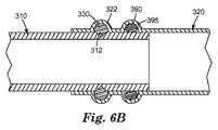
例えば、図6A及び6Bを参照すると、第1管310は、第1キー溝312及び第2キー溝322が実質的に位置合わせされるように第2管320に挿入される。形状記憶ポリマーを含むキー330は、第1キー溝312と第2キー溝322との間に形成された空洞に配置される。図示されるように、Oリング390は、第2管320の溝395に部分的に埋め込まれている。管接合部を接合すると、Oリング390は、第1管310と第2管320との間に配置され、封止(例えば流体密封封止)を形成する。一般に、Oリングは、第1管の平滑な外表面に押し付けられ、流体密封封止を形成する。いくつかの実施形態では、必要に応じて複数のOリング又は他の封止材を使用し、所望の封止を達成して漏れを防止してもよい。
For example, referring to FIGS. 6A and 6B, the
図6Bを参照すると、形状記憶ポリマーを例えばその転移温度を超えて加熱することで活性化するとき、キー330の長さは減少し、キーの長さに垂直な断面寸法は増加する。したがって、キー330は、第1管と第2管との間に機械的な干渉結合を提供し、一方でOリング390は、独自に所望の封止を提供する。
Referring to FIG. 6B, when the shape memory polymer is activated, for example, by heating beyond its transition temperature, the length of the key 330 decreases and the cross-sectional dimension perpendicular to the key length increases. Thus, the key 330 provides a mechanical interference coupling between the first and second tubes, while the O-
上記の実施形態は2本の管の接合について記載したが、その方法、材料、及び概念は他の管接合部にも同様に適用される。例えば、いくつかの実施形態では、管接合部の一方が、継ぎ手又は連結具、例えば、L字継ぎ手(45°又は90°L字継ぎ手など)、T字連結部、Y字連結部、十字継ぎ手、キャップ、径違い継ぎ手、エキスパンダーなどであってもよい。例えば、図7を参照すると、90°L字継ぎ手400が第1管410に接続されている。第1キー溝412は、第1管410の外表面に対する凹部である。第1管410は、90°L字継ぎ手400の第1末端部401に挿入されている。第1キー溝412は、L字継ぎ手400の第1末端部401の内表面に対する凹部である第2キー溝422と位置合わせされている。第1キー430は、第1キー溝412と第2キー溝422との間に形成された空洞に配置されている。活性化されると、形状記憶ポリマーは、断面が膨張し、第1キー溝412及び第2キー溝422を実質的に満たし、第1管410を機械的な干渉結合でL字継ぎ手400の第1末端部401に接合する。同様に、第2管接合部を90°L字継ぎ手400の第2末端部403に接合することができる。すなわち、第2管接合部は、第2管接合部のキー溝がL字継ぎ手400の第3キー溝423と位置合わせされるように、第2末端部403に挿入され得る。次に、形状記憶ポリマーキーを使用して、L字継ぎ手400と第2管との間に機械的な干渉結合を形成することができる。また、図示されていないが、L字継ぎ手の一方又は両方の末端部は、封止材(例えばOリング)を含んでいてもよい。
Although the above embodiments have described the joining of two tubes, the methods, materials, and concepts apply equally to other tube joints. For example, in some embodiments, one of the tube joints is a joint or connector, such as an L-shaped joint (such as a 45 ° or 90 ° L-shaped joint), a T-shaped joint, a Y-shaped joint, a cross joint. , Caps, joints with different diameters, expanders and the like. For example, referring to FIG. 7, a 90 ° L-shaped joint 400 is connected to the
いくつかの実施形態では、第1及び第2管接合部のキー溝の位置合わせは、止め具の使用により容易に行うことができる。図8及び9を参照すると、第1管510は、外表面514に対する凹部であり、第1管510の第1末端部501からL1の距離に配置された、第1キー溝512を含む。
In some embodiments, the alignment of the keyways of the first and second tube joints can be facilitated by the use of stops. Referring to FIGS. 8 and 9, the
連結管520は、連結管520の内表面523に対する凹部である第2キー溝522を含む。連結管520は、内表面523から連結管520の中心方向に突出する止め具560も含む。止め具560は、第2キー溝522からL2の距離に配置されている。いくつかの実施形態では、止め具は円周環であってもよい。いくつかの実施形態では、止め具は1つ以上の別個の要素(例えば、杭)を含んでいてもよい。
The
図9を参照すると、第1管510が連結管520に挿入されている。距離L1及びL2は、第1管510の第1末端部501が止め具560に接触すると、第1管510を連結管520にそれ以上挿入できなくなり、第1キー溝512及び第2キー溝522が実質的に位置合わせされるように、選択され得る。活性化されると、キー530は、両方のキー溝を実質的に満たし、第1管と連結管との間に機械的な干渉結合を形成する。図8及び9の実施形態は管及び連結管について記載しているが、任意の2つの管接合部を使用してもよい。更に、例えば封止材(例えばOリング)など、様々な実施形態の他の機能を含むことができる。
Referring to FIG. 9, the
止め具の使用は、管組立品の形成方法を容易にすることもできる。例えば、止め具と第2キー溝との距離が既知である(例えば、統一又は測定されている)場合、配管工は、第1管接合部上で対応する第1キー溝を形成すべき位置を、迅速かつ容易に見つけることができる。その後、パイプカッターなどの一般的な工具を使用して、第1キー溝をその場で適所に形成することができる。 The use of a stop can also facilitate the method of forming the tube assembly. For example, if the distance between the stop and the second keyway is known (eg, unified or measured), the plumber should position the corresponding first keyway on the first pipe joint Can be found quickly and easily. Thereafter, the first keyway can be formed in place using a common tool such as a pipe cutter.
いくつかの実施形態では、本開示のキーは、迅速で便利な管接合部の接合方法をもたらす。いくつかの実施形態では、方法は可逆的である。一般に、第1管接合部は、第1管接合部の外表面に対する凹部である第1キー溝を含むのに対し、第2管接合部は、第2管接合部の内表面に対する凹部である第2キー溝を含む。これらのキー溝は、例えば、キャスティング及びモールディング(すなわち、元の管接合部のキャスティング又はモールディング時にキー溝を形成する)、又は機械加工(例えば、管接合部の形成後に管接合部にキー溝を研削又は彫刻する)などの任意の既知の手段で形成され得る。 In some embodiments, the keys of the present disclosure provide a quick and convenient method of joining pipe joints. In some embodiments, the method is reversible. In general, the first pipe joint includes a first key groove that is a recess with respect to the outer surface of the first pipe joint, whereas the second pipe joint is a recess with respect to the inner surface of the second pipe joint. Includes a second keyway. These keyways can be, for example, cast and molded (ie, forming a keyway during casting or molding of the original pipe joint), or machined (eg, keying the pipe joint after forming the pipe joint). Can be formed by any known means such as grinding or engraving).
一般に、キー溝の形状及び寸法は特に限定されない。いくつかの実施形態では、特に管壁の寸法を決めた後でキー溝を形成する場合、キー溝の最大深さは、管の壁厚、及びキー溝領域の管の最小許容残存厚により制限される。いくつかの実施形態では、キー溝の寸法は、所望の接合部強度を提供するように、キーの一時的(すなわち、可逆変形した)寸法及び永久的(すなわち、変形していない)寸法の両方と共に、選択され得る。 In general, the shape and dimensions of the keyway are not particularly limited. In some embodiments, particularly when the keyway is formed after sizing the tube wall, the maximum keyway depth is limited by the wall thickness of the tube and the minimum allowable remaining thickness of the tube in the keyway region. Is done. In some embodiments, the keyway dimensions are both temporary (ie, reversibly deformed) and permanent (ie, undeformed) dimensions of the key to provide the desired joint strength. And can be selected.
いくつかの実施形態では、キー溝は、管の一面に対する凹部であり、反対面に対する凸部であってもよい。例えば、図1Aを参照すると、第1キー溝112は、管110の外表面114に対する凹部であり、内表面に対する凸部である。すなわち、第1キー溝112は、管110の中心方向に突出しており、管を通過する流動経路を部分的に妨害する(図5Aの第1凹部212a、212b、及び212cも参照されたい)。同様に、第2キー溝122は、管120の内表面123に対する凹部であり、反対の外表面に対する凸部である。すなわち、第2キー溝122は、第2管120の中心から外側に突出している(図5Aの第2凹部222a、222b、及び222cも参照されたい)。
In some embodiments, the keyway is a recess on one side of the tube and a protrusion on the opposite side. For example, referring to FIG. 1A, the
いくつかの実施形態では、反対面については平坦のままである、一方又は両方のキー溝を有することが望ましいことがある。例えば、図6aに示されるように、第1キー溝312は、第1管310の外表面に対する凹部であるが、管310の中心方向には突出していない(図7の第1キー溝412及び図8の第1キー溝512も参照されたい)。したがって、図1の第1キー溝112とは異なり、図6aの第1キー溝312は、第1管310を通過する流体の流れを妨害しない。図示されていないが、いくつかの実施形態では、第2キー溝も第2管接合部の外表面から突出しないように形成され得る。ただし、このような突出は流れを妨害しないし、キー溝領域の管厚がより厚くなることから、第2管接合部の外表面から突出した第2キー溝を有することが望ましいことがある。
In some embodiments, it may be desirable to have one or both keyways that remain flat on the opposite side. For example, as shown in FIG. 6a, the
一般に、第1管接合部が第2管接合部に挿入され、第1キー溝及び第2キー溝が位置合わせされる。形状記憶ポリマーを含むキーが、第1キー溝と第2キー溝との間に配置される。いくつかの実施形態では、第1及び第2管接合部の少なくとも一方のキー溝の深さ及び幅は、キーがそのキー溝からごくわずかしか突出しないか又は全く突出しないようにキー溝内に埋め込まれるのに十分である。一般に、キーがキー溝からいくらかでも突出していると、第1管接合部の第2管接合部への挿入を妨害することがある。したがって、いくつかの実施形態では、キーは、第1管接合部を第2管接合部に挿入する前にキー溝に完全に埋め込まれる。 Generally, the first pipe joint is inserted into the second pipe joint, and the first key groove and the second key groove are aligned. A key including a shape memory polymer is disposed between the first keyway and the second keyway. In some embodiments, the depth and width of the keyway of at least one of the first and second tube joints is within the keyway so that the key protrudes very little or not from the keyway. Enough to be embedded. In general, if the key protrudes somewhat from the keyway, insertion of the first pipe joint into the second pipe joint may be hindered. Thus, in some embodiments, the key is fully embedded in the keyway prior to inserting the first tube joint into the second tube joint.
管接合部が所望どおりに位置合わせされたら、例えば形状記憶ポリマーをその転移温度を超えて加熱することにより、キーを活性化することができる。活性化前に、管接合部を調整、又は更には分離することもできる。したがって、いくつかの実施形態では、本開示の方法により、隣接する管、継ぎ手、又は連結具間に何らかの永久的接続を形成する前に、パイプラインを共に「乾式嵌合」することができる。 Once the tube joint is aligned as desired, the key can be activated, for example, by heating the shape memory polymer above its transition temperature. Prior to activation, the tube joint can be adjusted or even separated. Thus, in some embodiments, the methods of the present disclosure can “dry fit” pipelines together before making any permanent connection between adjacent tubes, fittings, or couplings.
活性化されると、キーは、その永久的な変形していない寸法に戻る傾向がある。すなわち、キーは、減少したキーの長さに相当する第1キー溝及び第2キー溝の両方の部分を少なくとも部分的に満たすように、長さが減少し、長さに垂直な断面が膨張する。キーは、最初はごくわずかしか突出しないか又は全く突出しないようにキー溝内に配置されているが、加熱されると、断面寸法が両方のキー溝の深さを少なくとも部分的に満たす(いくつかの実施形態では、実質的に満たす)のに十分膨張する。十分に膨張して両方のキー溝の深さを満たすために、いくつかの実施形態では、長さが大きく減少する、例えば、長さが少なくとも10%減少することが必要である。 When activated, the key tends to return to its permanent undeformed dimensions. That is, the key is reduced in length and expanded in cross section perpendicular to the length so as to at least partially fill both portions of the first and second keyways corresponding to the reduced key length. To do. The key is initially placed in the keyway so that it protrudes very little or not at all, but when heated, the cross-sectional dimensions will at least partially fill the depth of both keyways (how many In such embodiments, it expands sufficiently to substantially fill). In order to fully expand to fill both keyway depths, in some embodiments it is necessary to greatly reduce the length, eg, reduce the length by at least 10%.
一般に、本開示の方法は、例えば、2本の管、管及び連結具、又は管及び継ぎ手などの、隣接する管接合部間に機械的な接合部を提供する。したがって、いくつかの実施形態では、本開示の方法は、第1管接合部と第2管接合部との間に機械的な干渉結合を形成するようにキーを冷却する工程を更に含む。 In general, the disclosed method provides a mechanical joint between adjacent pipe joints, such as, for example, two pipes, pipes and fittings, or pipes and fittings. Thus, in some embodiments, the method of the present disclosure further includes cooling the key to form a mechanical interference coupling between the first tube joint and the second tube joint.
いくつかの実施形態では、形成された接合部は可逆的である。例えば、いくつかの実施形態では、キーを形状記憶ポリマーの転移温度を超えて再加熱することができる。次に、第1管接合部を第2管接合部に対して再配置してもよい。キーを再冷却すると、第1管接合部と第2管接合部との間に機械的な干渉結合が再形成され得る。したがって、従来の管接合方法、例えば、接着剤及びはんだでは、多くの場合に接着剤又ははんだによる接合部を切除し、隙間を補うために新たな接合部を嵌め込むことが求められるが、これらとは異なり、管接合部を最小限の労力及び修正で調整することができる。 In some embodiments, the formed junction is reversible. For example, in some embodiments, the key can be reheated above the transition temperature of the shape memory polymer. Next, the first pipe joint may be rearranged with respect to the second pipe joint. When the key is recooled, a mechanical interference coupling can be re-created between the first tube joint and the second tube joint. Therefore, conventional pipe joining methods, such as adhesives and solders, often require cutting out joints with adhesives or solders and fitting new joints to make up for gaps. Unlike, pipe joints can be adjusted with minimal effort and modification.
いくつかの実施形態では、本開示の方法及び材料は、管網を修復する便利な手段をも提供する。例えば、いくつかの実施形態では、特定の管接合部を定位置に維持しているキーを再加熱し、その管接合部を取り外すことができる。次に、新たな同じ又は異なる管接合部を適切なキーと共に挿入することができる。その後、新たなキーの形状記憶ポリマーを活性化することで、得られた機械的な締まり嵌めにより、新たな管接合部を定位置にしっかり固定することができる。 In some embodiments, the methods and materials of the present disclosure also provide a convenient means of repairing the tube network. For example, in some embodiments, a key that maintains a particular tube joint in place can be reheated and the tube joint removed. A new same or different tube joint can then be inserted with the appropriate key. Thereafter, the new key joint shape memory polymer can be activated to secure the new pipe joint in place with the resulting mechanical interference fit.
実施例1.触媒原液を作製するために、窒素下でオーブン乾燥した500mLフラスコにWCl6(2.00g、0.005mol、Sigma−Aldrich(St.Louis,Missouri))及びトルエン約100mL(無水、Sigma−Aldrich(St.Louis,MO))を投入した。この混合物を窒素でパージしながら1時間攪拌した。ノニルフェノール(1.1g,0.005mol,Sigma−Aldrich)を注射器で加え、溶液を窒素パージ下で4時間攪拌した。次に、注射器を使用して、2,4−ペンタンジオン(0.77g、0.008mol、Acros Organics)を加え、溶液を窒素パージ下で17時間攪拌した。無水ジシクロペンタジエン(250mL、1.84mol、TCI Americaから入手、エチリデンノルボルネン含有量4%)を添加した。フラスコを60℃の油浴に配置し、溶液を1.5時間真空吸引して、トルエン及び他の揮発性物質(一部のジシクロペンタジエンなど)を除去した。この時点で、追加のジシクロペンタジエンを加えて溶液の総重量を最大250gに戻し、2,4−ペンタンジオンの追加充填分(0.77g、0.008mol、Acros Organics)を加えた。 Example 1. To make the catalyst stock solution, a 500 mL flask oven-dried under nitrogen was charged with WCl 6 (2.00 g, 0.005 mol, Sigma-Aldrich (St. Louis, Missouri)) and about 100 mL toluene (anhydrous, Sigma-Aldrich ( St. Louis, MO)). The mixture was stirred for 1 hour while purging with nitrogen. Nonylphenol (1.1 g, 0.005 mol, Sigma-Aldrich) was added via syringe and the solution was stirred for 4 hours under a nitrogen purge. Then, using a syringe, 2,4-pentanedione (0.77 g, 0.008 mol, Acros Organics) was added and the solution was stirred for 17 hours under a nitrogen purge. Anhydrous dicyclopentadiene (250 mL, 1.84 mol, obtained from TCI America, 4% ethylidene norbornene content) was added. The flask was placed in a 60 ° C. oil bath and the solution was vacuumed for 1.5 hours to remove toluene and other volatiles (such as some dicyclopentadiene). At this point, additional dicyclopentadiene was added to bring the total weight of the solution back to a maximum of 250 g and an additional charge of 2,4-pentanedione (0.77 g, 0.008 mol, Acros Organics) was added.
この触媒原液を以下のように使用して、反応性混合物Aを作製した。オーブン乾燥した125mL三角フラスコを隔膜で塞ぎ、窒素でパージした。注射器を使用して、5−エチリデン−2−ノルボルネン(9.1mL、Acros Organics)、トリクロロ酢酸エチル(0.08mL、Aldrich Chemical)、及び上記の触媒原液2.8mLを加えた。 Reactive mixture A was made using this catalyst stock solution as follows. An oven dried 125 mL Erlenmeyer flask was sealed with a septum and purged with nitrogen. Using a syringe, 5-ethylidene-2-norbornene (9.1 mL, Acros Organics), ethyl trichloroacetate (0.08 mL, Aldrich Chemical), and 2.8 mL of the above catalyst stock solution were added.
反応性混合物Bを以下のように調製した。IRGANOX 1010フェノール酸化防止剤(0.22g、Ciba Specialty Chemical Corp(Tarrytown,NY))をオーブン乾燥した125mL三角フラスコの中に入れた後、これを隔膜で塞ぎ、窒素でパージした。エチリデンノルボルネン(8.3mL)及びSANTICIZER 261aフタル酸可塑剤(2.4mL、Ferro Corp.)を加え、IRGANOX 1010が溶解するまで混合物を攪拌した。次に、10vol %のジエチルアルミニウムクロリド(Sigma−Aldrich(St.Louis,MO))のジシクロペンタジエン溶液を1.0mL加えた。 Reactive mixture B was prepared as follows. IRGANOX 1010 phenolic antioxidant (0.22 g, Ciba Specialty Chemical Corp (Tarrytown, NY)) was placed in an oven-dried 125 mL Erlenmeyer flask, which was then sealed with a septum and purged with nitrogen. Ethylidene norbornene (8.3 mL) and SANTICIZER 261a phthalate plasticizer (2.4 mL, Ferro Corp.) were added and the mixture was stirred until IRGANOX 1010 was dissolved. Next, 1.0 mL of a 10 mol% diethylaluminum chloride (Sigma-Aldrich (St. Louis, MO)) dicyclopentadiene solution was added.
反応性混合物A及びBを混合し、円弧形状の形状記憶ポリマーを形成した。反応性混合物A(11mL)を注射器に充填した。別の注射器に反応性混合物B(11mL)を充填した。注射器を注射器ポンプに装填し、静的ミキサーに接続した。30秒未満の間に、2つの溶液を内径4.8mm(0.19インチ)の可撓性プラスチックチューブに注入した。試料は硬化するにつれて発熱し、その後、得られた形状記憶ポリマーをチューブから取り出した。 Reactive mixtures A and B were mixed to form an arc-shaped shape memory polymer. Reactive mixture A (11 mL) was filled into a syringe. A separate syringe was charged with reactive mixture B (11 mL). The syringe was loaded into a syringe pump and connected to a static mixer. Within less than 30 seconds, the two solutions were injected into a flexible plastic tube with an inner diameter of 4.8 mm (0.19 inch). The sample exothermed as it cured, and then the resulting shape memory polymer was removed from the tube.
次に棒状のポリマーを長さ10.2cm(4インチ)の断片に切断した。これらの断片を120℃の炉内で加熱し、直径が2.3mm(0.09インチ)に減少するまで手で伸ばし、冷却すると、断片はこの伸びた形状を維持した。次に、これらの棒を直径2.4cm(0.96インチ)の銅管継ぎ手に3回巻き付けてコイルにし、コイルの末端部を共に固定した。その後、このコイルを70℃の炉内で10分間加熱した。冷却後、コイルは、管継ぎ手から取り外されてもそのコイル形状を維持した。次に、このコイルを約270°の弧状に切断し、やすりをかけてその厚さを2.0mm(0.08インチ)まで減らし、キーを形成した。 The rod-like polymer was then cut into pieces of 10.2 cm (4 inches) in length. When the pieces were heated in a 120 ° C. oven and stretched by hand until the diameter was reduced to 2.3 mm (0.09 inches) and cooled, the pieces maintained their stretched shape. These rods were then wound three times around a 2.4 cm (0.96 inch) diameter copper tube joint into a coil, and the ends of the coil were secured together. Thereafter, the coil was heated in a 70 ° C. furnace for 10 minutes. After cooling, the coil maintained its coil shape even when it was removed from the pipe joint. The coil was then cut into an arc of about 270 ° and filed to reduce its thickness to 2.0 mm (0.08 inch) to form a key.
その後、このキーを銅管連結管の内側のキー溝に挿入した。連結管は、内径が22.4mm(0.88インチ)であり、連結管のキー溝は、キーがキー溝内にあるとき、キーが継ぎ手の内腔を妨害しないように十分深かった。外径22.1mm(0.87インチ)の銅管の断片の、一方の末端部から6.4mm(0.25インチ)の全周に管カッターで刻み目を付けた。次に、やすりを使用して、この最初の刻み目を深さ0.30mm(0.012インチ)、幅1.8mm(0.07インチ)のキー溝に広げた。その後、この管を連結管に挿入し、管のキー溝が連結管内のキー溝に隣接するように置き、キーをキー溝間に配置した。組立品を150℃の炉内で5分間加熱した。冷却後、管は連結管内にしっかり取り付けられており、管を連結管から手で取り外すことはできなかった。 Thereafter, this key was inserted into the key groove inside the copper pipe connecting pipe. The connecting tube had an inner diameter of 22.4 mm (0.88 inch) and the keyway of the connecting tube was deep enough so that when the key was in the keyway, the key did not obstruct the lumen of the joint. A piece of copper tube with an outer diameter of 22.1 mm (0.87 inch) was scored with a tube cutter around the entire circumference of 6.4 mm (0.25 inch) from one end. Next, a file was used to spread this initial indentation into a keyway having a depth of 0.30 mm (0.012 inches) and a width of 1.8 mm (0.07 inches). Thereafter, this tube was inserted into the connecting tube, and the key groove of the tube was placed adjacent to the key groove in the connecting tube, and the key was placed between the key grooves. The assembly was heated in a 150 ° C. oven for 5 minutes. After cooling, the tube was firmly attached in the connecting tube, and the tube could not be manually removed from the connecting tube.
嵌合を外すために、管/連結管組立品を150℃の炉内で5分間再加熱した。まだ熱いうちに、管を連結管から手でうまく引き離した。キーを取り外して、長さが短くなり、厚さが3.8mm(0.15インチ)に増加していることを確認した。 To disengage, the tube / connector tube assembly was reheated in a 150 ° C. oven for 5 minutes. While still hot, the tube was pulled away from the connecting tube by hand. The key was removed and it was confirmed that the length was shortened and the thickness was increased to 3.8 mm (0.15 inch).
実施例2.実施例1に記載の直径2.3mm(0.09インチ)の伸びた形状の形状記憶ポリマーの棒状断片を、外径1.6cm(0.62インチ)の銅管に2回巻き付けてコイルにし、コイルの末端部を共に固定した。次に、このコイルを、見た目が柔らかくなり、管の周囲にしっかり締まるまで、ヒートガンで緩やかに加熱した。冷却後、コイルは、管継ぎ手から取り外されてもコイル形状を維持した。次に、このコイルをそれぞれ約270°の2つのキーに切断した。 Example 2 An elongated shape memory polymer rod-shaped piece having a diameter of 2.3 mm (0.09 inch) described in Example 1 was wound twice around a copper tube having an outer diameter of 1.6 cm (0.62 inch) to form a coil. The ends of the coil were fixed together. The coil was then gently heated with a heat gun until it looked soft and tightened around the tube. After cooling, the coil maintained its coil shape even when it was removed from the pipe joint. The coil was then cut into two keys of approximately 270 ° each.
内径16.5mm(0.65インチ)の「StreamTech 2」銅連結管(Mueller Industriesから入手)を、2つの外側のOリング封止材をその溝から取り外すことにより改造したが、2つの内側のOリング封止材は定位置のままその溝に残した。次に、形状記憶ポリマーキーを連結管の2つの最も外側の溝(すなわち、キー溝)に挿入した。ポリマーキーの内側にやすりをかけて、継ぎ手の内腔に突出するポリマーをいずれも除去した。 A 16.5 mm (0.65 inch) ID “StreamTech 2” copper connection tube (obtained from Mueller Industries) was modified by removing the two outer O-ring seals from its groove, but the two inner The O-ring sealant was left in place in the groove. The shape memory polymer key was then inserted into the two outermost grooves (ie, key grooves) of the connecting tube. A file was applied to the inside of the polymer key to remove any polymer protruding into the lumen of the joint.
2つの外径15.7mm(0.62インチ)の銅管の断片に、一方の末端部から23mm(0.9インチ)の全周に管カッターで刻み目を付けた。次に、やすりを使用して、これらの最初の刻み目を深さ約0.30mm(0.012インチ)、幅1.8mm(0.07インチ)のキー溝に広げた。その後、管を銅連結管の各末端部に挿入した。管のキー溝が連結管内の外側の溝(キー溝)に隣接するように置き、キーをキー溝間に配置した。この組立品をヒートガンで45秒間加熱した。冷却後、管は連結管内にしっかり取り付けられており、手で取り外すことはできなかった。 Two 15.7 mm (0.62 inch) outer diameter copper tube segments were scored with a tube cutter around the entire circumference of 23 mm (0.9 inch) from one end. A file was then used to spread these initial indentations into a keyway approximately 0.30 mm (0.012 inches) deep and 1.8 mm (0.07 inches) wide. Thereafter, the tube was inserted into each end of the copper connecting tube. The key groove of the tube was placed adjacent to the outer groove (key groove) in the connecting tube, and the key was placed between the key grooves. The assembly was heated with a heat gun for 45 seconds. After cooling, the tube was firmly attached in the connecting tube and could not be removed by hand.
管組立品の末端部をそれぞれ再循環水浴に接続し、水を送って銅管組立品に通した。水温を25℃から80℃に上昇させ、その後、80℃で30分間維持した。管組立品からの水漏れはなかった。 Each end of the tube assembly was connected to a recirculating water bath and water was pumped through the copper tube assembly. The water temperature was raised from 25 ° C. to 80 ° C. and then maintained at 80 ° C. for 30 minutes. There was no water leakage from the tube assembly.
実施例3.直径6mm(0.25インチ)、長さ30.5cm(12インチ)のABS(アクリロニトリル−ブタジエン−スチレンコポリマー)の棒(Plastics International(Eden Prairie,MN)から入手)を140℃の炉内で加熱した。次に、棒を手で伸ばし、冷却させて、直径が3〜4mm(0.12〜0.16インチ)に減少した伸びた棒を得た。この伸びた棒を外径22.1mm(0.87インチ)の銅管に2回巻き付けてコイルにし、コイルの末端部を共に固定した。次に、このコイルを、見た目が柔らかくなり、管の周囲にしっかり締まるまで、ヒートガンで緩やかに加熱した。冷却後、コイルは、管継ぎ手から取り外してもコイル形状を維持した。次に、このコイルを約270°の弧状に切断し、キーを形成した。 Example 3 A 6 mm (0.25 inch) diameter, 30.5 cm (12 inch) ABS (acrylonitrile-butadiene-styrene copolymer) rod (obtained from Plastics International (Eden Prairie, MN)) heated in a 140 ° C. oven. did. The rod was then stretched by hand and allowed to cool to obtain an elongated rod having a diameter reduced to 3-4 mm (0.12-0.16 inches). The elongated bar was wound twice around a copper tube having an outer diameter of 22.1 mm (0.87 inch) to form a coil, and both ends of the coil were fixed together. The coil was then gently heated with a heat gun until it looked soft and tightened around the tube. After cooling, the coil maintained its coil shape even when it was removed from the pipe joint. Next, this coil was cut into an arc of about 270 ° to form a key.
このABS形状記憶ポリマーキーを、実施例1で使用した管連結管のキー溝に挿入した。ポリマーキーの内側にやすりをかけて、キー溝から継ぎ手の内腔に突出するポリマーをいずれも除去した。管のキー溝が連結管のキー溝の位置に合うように実施例1の管を連結管に挿入し、ABS形状記憶ポリマーキーを2つのキー溝間に配置した。この組立品をヒートガンで90秒間加熱した。冷却後、管は連結管内にしっかり取り付けられており、手で取り外すことはできなかった。 This ABS shape memory polymer key was inserted into the key groove of the pipe connecting pipe used in Example 1. A file was applied to the inside of the polymer key to remove any polymer protruding from the keyway into the joint lumen. The tube of Example 1 was inserted into the connecting tube so that the keyway of the tube matched the position of the keyway of the connecting tube, and the ABS shape memory polymer key was placed between the two keyways. The assembly was heated with a heat gun for 90 seconds. After cooling, the tube was firmly attached in the connecting tube and could not be removed by hand.
嵌合を外すために、管/連結管組立品をヒートガンで60秒間再加熱した。まだ熱いうちに、管を連結管から手でうまく引き離した。形状記憶ポリマーキーを取り外して、長さが30%を超えて短くなっていることを確認した。 To disengage, the tube / connector tube assembly was reheated with a heat gun for 60 seconds. While still hot, the tube was pulled away from the connecting tube by hand. The shape memory polymer key was removed and it was confirmed that the length was shorter than 30%.
本発明の様々な改変及び変更が、本発明の範囲及び趣旨から逸脱することなく当業者には明らかとなるであろう。 Various modifications and alterations of this invention will become apparent to those skilled in the art without departing from the scope and spirit of this invention.
Claims (2)
前記第1管接合部を前記第2管接合部に挿入する工程と、
前記第1キー溝及び前記第2キー溝を位置合わせする工程と、
第1転移温度を有する第1形状記憶ポリマーを含む第1キーを前記第1キー溝と前記第2キー溝との間に配置する工程であって、前記第1キーが長さと該長さに垂直な断面とを有する工程と、
前記第1キーを前記第1転移温度を超えて加熱する工程と、
前記第1形状記憶ポリマーが前記第1キー溝及び前記第2キー溝の両方の一部を満たすように前記第1キーの前記長さを減少させかつ前記断面を膨張させ、前記第1管接合部と前記第2管接合部との間に機械的な干渉結合を形成する工程と、を含み、
前記第1キー溝が複数の第1凹部を含み、前記第2キー溝が複数の第2凹部を含み、前記第1キーが複数の弧状部を含み、各弧状部が形状記憶ポリマーを含み、前記第1キー溝及び前記第2キー溝を位置合わせする工程が、前記第1凹部の少なくとも一部を前記第2凹部の少なくとも一部と位置合わせして、複数の対になった第1及び第2凹部を形成する工程を含み、前記第1転移温度を有する前記第1形状記憶ポリマーを含む前記第1キーを前記第1キー溝と前記第2キー溝との間に配置する工程が、少なくとも1つの弧状部を2つ以上の対になった第1及び第2凹部の間に配置する工程を含む、方法。 A first pipe joint including a first key groove that is a recess with respect to the outer surface of the first pipe joint is joined to a second pipe joint including a second key groove that is a recess with respect to the inner surface of the second pipe joint. A way to
Inserting the first pipe joint into the second pipe joint;
Aligning the first keyway and the second keyway;
Disposing a first key including a first shape memory polymer having a first transition temperature between the first keyway and the second keyway, wherein the first key has a length and a length. A step having a vertical cross-section;
Heating the first key beyond the first transition temperature;
Reducing the length of the first key and expanding the cross-section so that the first shape memory polymer fills part of both the first keyway and the second keyway; Forming a mechanical interference coupling between the portion and the second pipe joint,
The first key groove includes a plurality of first recess, the second key groove includes the plurality of second recesses, said first key comprises a plurality of arcuate portions, each arcuate portion comprises a shape memory polymer , the first key groove and the step of aligning the second keyway, before SL by at least a portion of the first recess is aligned with at least a portion of the second recess, it has become more pairs look including the step of forming the first and second recesses, positioning the first keys including the first shape memory polymer having a first transition temperature between the first keyway and the second keyway The method includes placing at least one arcuate portion between two or more pairs of first and second recesses .
第2管接合部の内表面に対する凹部である第2キー溝を含む第2管接合部と、
第1形状記憶ポリマーを含む第1キーと、を含み、
前記第1管接合部の少なくとも一部が、前記第1キー溝を前記第2キー溝と位置合わせするように前記第2管接合部の内側に配置され、前記第1キーが、前記第1キー溝と前記第2キー溝との間に位置し、前記第1キー溝及び前記第2キー溝を少なくとも部分的に満たし、
前記第1キー溝が複数の第1凹部を含み、前記第2キー溝が複数の第2凹部を含み、前記第1キーが複数の弧状部を含み、各弧状部が形状記憶ポリマーを含み、前記第1キー溝及び前記第2キー溝が、前記第1凹部の少なくとも一部を前記第2凹部の少なくとも一部と位置合わせして、複数の対になった第1及び第2凹部を形成するように位置合わせされ、前記形状記憶ポリマーを含む前記弧状部が、前記対になった第1及び第2凹部の間に位置し、前記対になった第1及び第2凹部を少なくとも部分的に満たす、接合管組立品。 A first pipe joint including a first key groove that is a recess with respect to the outer surface of the first pipe joint;
A second pipe joint including a second key groove that is a recess with respect to the inner surface of the second pipe joint;
A first key comprising a first shape memory polymer,
At least a part of the first pipe joint is disposed inside the second pipe joint so as to align the first key groove with the second key groove, and the first key is the first key. Located between the keyway and the second keyway, at least partially filling the first keyway and the second keyway;
The first key groove includes a plurality of first recess, the second key groove includes the plurality of second recesses, said first key comprises a plurality of arcuate portions, each arcuate portion comprises a shape memory polymer the first key groove and the second keyway, said at least a portion of the first recess in alignment with at least a portion of the second recess, the first and second recesses were in a plurality of pairs aligned so as to form, the arc-shaped portion including the shape memory polymer is positioned between the first and second recesses became the pair, at least in part the first and second recesses became the pair A joint pipe assembly that meets the requirements.
Applications Claiming Priority (3)
| Application Number | Priority Date | Filing Date | Title |
|---|---|---|---|
| US26159509P | 2009-11-16 | 2009-11-16 | |
| US61/261,595 | 2009-11-16 | ||
| PCT/US2010/056377 WO2011060167A2 (en) | 2009-11-16 | 2010-11-11 | Pipe section joining |
Publications (3)
| Publication Number | Publication Date |
|---|---|
| JP2013511010A JP2013511010A (en) | 2013-03-28 |
| JP2013511010A5 JP2013511010A5 (en) | 2013-12-19 |
| JP5907878B2 true JP5907878B2 (en) | 2016-04-26 |
Family
ID=43992401
Family Applications (1)
| Application Number | Title | Priority Date | Filing Date |
|---|---|---|---|
| JP2012538981A Expired - Fee Related JP5907878B2 (en) | 2009-11-16 | 2010-11-11 | Joining pipe joints |
Country Status (6)
| Country | Link |
|---|---|
| US (1) | US8870236B2 (en) |
| EP (1) | EP2501976B1 (en) |
| JP (1) | JP5907878B2 (en) |
| KR (1) | KR20120089749A (en) |
| CN (1) | CN102686928B (en) |
| WO (1) | WO2011060167A2 (en) |
Families Citing this family (14)
| Publication number | Priority date | Publication date | Assignee | Title |
|---|---|---|---|---|
| US8047844B2 (en) | 2009-07-16 | 2011-11-01 | Rodo Medical, Inc. | Dental rentention systems |
| FR2963654B1 (en) * | 2010-08-06 | 2013-12-13 | Saipem Sa | DRIVING COMPRISING AN INTERNAL SHAPING AND A TUBULAR JUNCTION SLEEVE OF PLASTIC MATERIAL |
| EP2481966A1 (en) * | 2011-02-01 | 2012-08-01 | Uponor Innovation AB | Clamping ring |
| US9168111B2 (en) * | 2011-02-04 | 2015-10-27 | Rodo Medical, Inc. | Abutment devices and methods for natural teeth |
| US9623813B2 (en) * | 2013-11-14 | 2017-04-18 | GM Global Technology Operations LLC | Fit and finish methods |
| US9719536B2 (en) * | 2014-07-03 | 2017-08-01 | The Boeing Company | Assemblies including shape memory alloy fittings and composite structural members |
| DE102014010899A1 (en) * | 2014-07-24 | 2016-01-28 | Wabco Gmbh | Rotatable axially locking and pressure-resistant cable connection |
| KR101702881B1 (en) * | 2014-12-11 | 2017-02-07 | 하대환 | Pipe connection structure for the filament winding |
| US10927987B2 (en) * | 2015-09-22 | 2021-02-23 | Raytheon Company | Duct with shape memory material, and installation method |
| US20180038400A1 (en) * | 2016-08-08 | 2018-02-08 | GM Global Technology Operations LLC | Coupling system |
| CN107687178A (en) * | 2017-09-04 | 2018-02-13 | 滨州学院 | A kind of precast assembly comprehensive pipe gallery structure of anti-uneven settlement of foundation |
| US11267236B2 (en) * | 2018-03-16 | 2022-03-08 | Divergent Technologies, Inc. | Single shear joint for node-to-node connections |
| CN112096978A (en) * | 2020-09-26 | 2020-12-18 | 中国石油天然气集团有限公司 | Thin-walled pipe connecting structure |
| CN114001225B (en) * | 2021-09-13 | 2023-06-16 | 安徽省宏忆新型材料有限公司 | Inlay suite for sealing composite material groove and application method thereof |
Family Cites Families (47)
| Publication number | Priority date | Publication date | Assignee | Title |
|---|---|---|---|---|
| GB650573A (en) * | 1947-02-20 | 1951-02-28 | Motor Columbus Ag Fuer Elek Sc | Improvements in and relating to rigid pipe connections |
| SE428596B (en) | 1975-04-09 | 1983-07-11 | Raychem Corp | DEVICE FOR CONNECTING SUBSTRATE EXV RODS INCLUDING A MEMORIAL METAL BODY |
| US4426761A (en) * | 1981-05-21 | 1984-01-24 | Mcinerney Spring And Wire Company | Pipe clamp and method of clamping |
| US4436858A (en) | 1982-05-14 | 1984-03-13 | Hercules Incorporated | Plasticized polydicyclopentadiene and a method for making the same |
| US4650228A (en) * | 1983-09-14 | 1987-03-17 | Raychem Corporation | Heat-recoverable coupling assembly |
| JPS6081572A (en) | 1983-10-07 | 1985-05-09 | Hitachi Tokyo Electronics Co Ltd | Sealing mechanism |
| US5506300A (en) | 1985-01-04 | 1996-04-09 | Thoratec Laboratories Corporation | Compositions that soften at predetermined temperatures and the method of making same |
| US4832382A (en) | 1987-02-19 | 1989-05-23 | Raychem Corporation | Coupling device |
| US4872713A (en) | 1987-02-19 | 1989-10-10 | Raychem Corporation | Coupling device |
| JPS63152996U (en) * | 1987-03-27 | 1988-10-06 | ||
| FR2616197B1 (en) | 1987-06-05 | 1989-10-13 | Hutchinson | DEVICE FOR CONNECTING A TUBE, BELLOWS OR THE LIKE TO A TIP USING A MEMORY-SHAPED ALLOY MEMBER AND METHOD FOR MOUNTING IT |
| JP2502132B2 (en) | 1988-09-30 | 1996-05-29 | 三菱重工業株式会社 | Shape memory polyurethane elastomer molded body |
| JPH02121907A (en) | 1988-10-31 | 1990-05-09 | Mitsubishi Heavy Ind Ltd | Cosmetic for human |
| JP2959775B2 (en) | 1988-11-11 | 1999-10-06 | 日本ゼオン株式会社 | Material for shape memory molding |
| JPH02158483A (en) * | 1988-12-09 | 1990-06-18 | Matsushita Electric Ind Co Ltd | Bicycle frame |
| JPH02163594A (en) | 1988-12-19 | 1990-06-22 | Mitsubishi Heavy Ind Ltd | Pipe connecting method using shape memory polymer |
| US4934743A (en) | 1989-02-07 | 1990-06-19 | Raychem Corporation | Assembly for forming a mechanical connection to an object |
| JP2505568B2 (en) | 1989-02-27 | 1996-06-12 | 積水化学工業株式会社 | Connection structure of lining steel pipe |
| KR910004768Y1 (en) * | 1989-07-05 | 1991-07-04 | 최의영 | Connector of pipes |
| JPH03265784A (en) | 1990-03-12 | 1991-11-26 | Sekisui Chem Co Ltd | Pipe fitting |
| GB9007284D0 (en) | 1990-03-31 | 1990-05-30 | Ciba Geigy Ag | Production of pigments |
| US5665822A (en) | 1991-10-07 | 1997-09-09 | Landec Corporation | Thermoplastic Elastomers |
| JPH04282093A (en) | 1991-03-06 | 1992-10-07 | Maezawa Kiyuusou Kogyo Kk | Pipe connecting method |
| JPH053776U (en) * | 1991-07-04 | 1993-01-22 | 株式会社クボタ | Insertion ring for pipe fittings |
| JPH05133488A (en) * | 1991-11-08 | 1993-05-28 | Furukawa Electric Co Ltd:The | Liner for pipe joint using shape memory alloy |
| JPH0784913B2 (en) * | 1993-01-22 | 1995-09-13 | 岩谷産業株式会社 | Metal tube connection method |
| JPH07126125A (en) | 1993-11-08 | 1995-05-16 | Mitsubishi Heavy Ind Ltd | Make-up cosmetic |
| JP3265784B2 (en) | 1993-12-24 | 2002-03-18 | 日本油脂株式会社 | Additive for cement |
| US5989353A (en) | 1996-10-11 | 1999-11-23 | Mallinckrodt Baker, Inc. | Cleaning wafer substrates of metal contamination while maintaining wafer smoothness |
| JP3028215B2 (en) | 1997-07-02 | 2000-04-04 | 日本鋼管株式会社 | Plug-in type fitting |
| US6240630B1 (en) * | 1997-12-03 | 2001-06-05 | The Regents Of The University Of California | Apparatus for loading shape memory gripper mechanisms |
| KR100382568B1 (en) | 1998-02-23 | 2003-05-09 | 메사츄세츠 인스티튜트 어브 테크놀로지 | Biodegradable shape memory polymers |
| PL342996A1 (en) | 1998-02-23 | 2001-07-16 | Mnemoscience Gmbh | Shape memory polymers |
| KR100282510B1 (en) | 1998-05-14 | 2001-02-15 | 박실조 | Pipe connection structure and connection method |
| US6511253B1 (en) * | 1998-11-16 | 2003-01-28 | Steve Grimes | Method for mounting a housing to an object and devices related thereto |
| EP1492493A1 (en) | 2002-04-10 | 2005-01-05 | Mnemoscience GmbH | Method for the generation of memory effects on hair |
| US20040030062A1 (en) | 2002-05-02 | 2004-02-12 | Mather Patrick T. | Castable shape memory polymers |
| JP4530989B2 (en) | 2002-10-11 | 2010-08-25 | ユニバーシティ オブ コネチカット | Shape memory polymer |
| CN2596155Y (en) * | 2003-01-29 | 2003-12-31 | 中国科学院金属研究所 | Marmem pipe joint |
| KR20030066472A (en) | 2003-04-28 | 2003-08-09 | 김수근 | Valve Sill Pipe Joint Device |
| US7516990B2 (en) | 2003-05-15 | 2009-04-14 | Mueller Industries, Inc. | Fluid conduit system and fittings therefor |
| DE10334784A1 (en) | 2003-07-30 | 2005-03-03 | Mnemoscience Gmbh | Cosmetic composition with polyol / polyester block polymers |
| JP2006242285A (en) | 2005-03-03 | 2006-09-14 | Toyota Motor Corp | Sealing structure of pipe joint part |
| DE202005009018U1 (en) * | 2005-06-09 | 2006-10-19 | Voss Automotive Gmbh | Connecting device with media lines |
| US8083268B2 (en) | 2005-10-21 | 2011-12-27 | Mueller Industries, Inc. | Coupling, joint and method for fixedly and sealingly securing components to one another |
| EP1930605A1 (en) * | 2006-12-06 | 2008-06-11 | Uponor Innovation Ab | Fitting for a pipe, in particular a plastic pipe or a plastic / metal composite pipe |
| CN101126473A (en) * | 2007-07-30 | 2008-02-20 | 天力管件有限公司 | Metal pipe and shape memory alloy pipe joint connection method |
-
2010
- 2010-11-11 WO PCT/US2010/056377 patent/WO2011060167A2/en active Application Filing
- 2010-11-11 US US13/504,532 patent/US8870236B2/en not_active Expired - Fee Related
- 2010-11-11 JP JP2012538981A patent/JP5907878B2/en not_active Expired - Fee Related
- 2010-11-11 KR KR1020127015312A patent/KR20120089749A/en not_active Application Discontinuation
- 2010-11-11 CN CN201080051859.5A patent/CN102686928B/en not_active Expired - Fee Related
- 2010-11-11 EP EP10830730.7A patent/EP2501976B1/en not_active Not-in-force
Also Published As
| Publication number | Publication date |
|---|---|
| JP2013511010A (en) | 2013-03-28 |
| EP2501976B1 (en) | 2017-10-04 |
| US20120211119A1 (en) | 2012-08-23 |
| US8870236B2 (en) | 2014-10-28 |
| CN102686928B (en) | 2016-03-23 |
| WO2011060167A2 (en) | 2011-05-19 |
| KR20120089749A (en) | 2012-08-13 |
| CN102686928A (en) | 2012-09-19 |
| WO2011060167A3 (en) | 2011-09-22 |
| EP2501976A2 (en) | 2012-09-26 |
| EP2501976A4 (en) | 2014-04-02 |
Similar Documents
| Publication | Publication Date | Title |
|---|---|---|
| JP5907878B2 (en) | Joining pipe joints | |
| CN102459924B (en) | Blind fasteners | |
| RU2178355C2 (en) | Tubular product, methods for its production and use (versions) | |
| CN105637278B (en) | Pipe jointing part with dynamic axial restraint system | |
| GB2149468A (en) | Heat shrinkable pipe coupling | |
| WO2004042264A2 (en) | Plastic-lined metal-encased tubing segment connector system | |
| JP2002533639A (en) | Pipe coupling | |
| TWI660140B (en) | Coupling and seal | |
| TW201013079A (en) | Coupling, joint and method for fixedly and sealingly securing components to one another | |
| WO2010121339A1 (en) | Method for the highly-thick thermal coating of joints by using electrofusion in pipes used for conducting fluids, made of steel tubes externally coated with polyolefins | |
| WO1998041790A1 (en) | Method for making a pipe connection, and a pipe connection | |
| CA2156536C (en) | Pipe liner and method of installation | |
| WO2020117638A1 (en) | Apparatus and method for joining molecularly oriented pipe | |
| WO1999022170A1 (en) | Pipe joints | |
| CN111578008B (en) | Union connection structure with high polymer material lining and assembling method thereof | |
| KR101041167B1 (en) | Sealing method for pipe connecting parts of rf system using shape-memory alloy ring | |
| JPH08320095A (en) | Polyethylene pipe connecting method and polyethylene pipe | |
| RU2527282C2 (en) | External insulation of pipeline joint of steel pipes with outer coating | |
| EP1040293B1 (en) | Connector for thermoplastic pipe | |
| JP4246983B2 (en) | Pipe fitting | |
| JP3400955B2 (en) | Existing pipe rehabilitation pipe and existing pipe rehabilitation repair method | |
| JPH11170367A (en) | Method for lining inside of pipe | |
| WO2024091285A1 (en) | Pipe fittings and connector kits | |
| JP5508200B2 (en) | Piping material and manufacturing method thereof | |
| JP2935421B2 (en) | Electrofusion fittings |
Legal Events
| Date | Code | Title | Description |
|---|---|---|---|
| A521 | Request for written amendment filed |
Free format text: JAPANESE INTERMEDIATE CODE: A523 Effective date: 20131028 |
|
| A621 | Written request for application examination |
Free format text: JAPANESE INTERMEDIATE CODE: A621 Effective date: 20131028 |
|
| A977 | Report on retrieval |
Free format text: JAPANESE INTERMEDIATE CODE: A971007 Effective date: 20140827 |
|
| A131 | Notification of reasons for refusal |
Free format text: JAPANESE INTERMEDIATE CODE: A131 Effective date: 20140909 |
|
| A521 | Request for written amendment filed |
Free format text: JAPANESE INTERMEDIATE CODE: A523 Effective date: 20141104 |
|
| A131 | Notification of reasons for refusal |
Free format text: JAPANESE INTERMEDIATE CODE: A131 Effective date: 20150324 |
|
| A601 | Written request for extension of time |
Free format text: JAPANESE INTERMEDIATE CODE: A601 Effective date: 20150623 |
|
| A601 | Written request for extension of time |
Free format text: JAPANESE INTERMEDIATE CODE: A601 Effective date: 20150723 |
|
| A601 | Written request for extension of time |
Free format text: JAPANESE INTERMEDIATE CODE: A601 Effective date: 20150821 |
|
| A521 | Request for written amendment filed |
Free format text: JAPANESE INTERMEDIATE CODE: A523 Effective date: 20150924 |
|
| TRDD | Decision of grant or rejection written | ||
| A01 | Written decision to grant a patent or to grant a registration (utility model) |
Free format text: JAPANESE INTERMEDIATE CODE: A01 Effective date: 20160223 |
|
| A61 | First payment of annual fees (during grant procedure) |
Free format text: JAPANESE INTERMEDIATE CODE: A61 Effective date: 20160322 |
|
| R150 | Certificate of patent or registration of utility model |
Ref document number: 5907878 Country of ref document: JP Free format text: JAPANESE INTERMEDIATE CODE: R150 |
|
| LAPS | Cancellation because of no payment of annual fees |