JP5907510B2 - Slot machine - Google Patents
Slot machine Download PDFInfo
- Publication number
- JP5907510B2 JP5907510B2 JP2013209997A JP2013209997A JP5907510B2 JP 5907510 B2 JP5907510 B2 JP 5907510B2 JP 2013209997 A JP2013209997 A JP 2013209997A JP 2013209997 A JP2013209997 A JP 2013209997A JP 5907510 B2 JP5907510 B2 JP 5907510B2
- Authority
- JP
- Japan
- Prior art keywords
- reel
- stop
- symbol
- game
- pseudo
- Prior art date
- Legal status (The legal status is an assumption and is not a legal conclusion. Google has not performed a legal analysis and makes no representation as to the accuracy of the status listed.)
- Active
Links
- 230000000694 effects Effects 0.000 claims description 312
- 238000000034 method Methods 0.000 description 157
- 230000008569 process Effects 0.000 description 155
- 238000012545 processing Methods 0.000 description 75
- 239000002131 composite material Substances 0.000 description 33
- 238000003780 insertion Methods 0.000 description 31
- 230000037431 insertion Effects 0.000 description 31
- 238000004519 manufacturing process Methods 0.000 description 28
- 238000010586 diagram Methods 0.000 description 22
- 230000002441 reversible effect Effects 0.000 description 22
- 241000219109 Citrullus Species 0.000 description 21
- 235000012828 Citrullus lanatus var citroides Nutrition 0.000 description 21
- 230000007704 transition Effects 0.000 description 14
- 238000003860 storage Methods 0.000 description 12
- 230000000449 premovement Effects 0.000 description 11
- 230000001133 acceleration Effects 0.000 description 10
- 230000003247 decreasing effect Effects 0.000 description 10
- 238000013461 design Methods 0.000 description 9
- 230000002093 peripheral effect Effects 0.000 description 9
- 230000005540 biological transmission Effects 0.000 description 7
- 238000001514 detection method Methods 0.000 description 5
- 230000003111 delayed effect Effects 0.000 description 4
- 230000005856 abnormality Effects 0.000 description 3
- 230000001788 irregular Effects 0.000 description 3
- 241000167854 Bourreria succulenta Species 0.000 description 2
- 235000019693 cherries Nutrition 0.000 description 2
- 238000013500 data storage Methods 0.000 description 2
- 230000005284 excitation Effects 0.000 description 2
- 239000004973 liquid crystal related substance Substances 0.000 description 2
- 230000010355 oscillation Effects 0.000 description 2
- 238000004904 shortening Methods 0.000 description 2
- 241000494579 Fritillaria pudica Species 0.000 description 1
- 240000007942 Prunus pensylvanica Species 0.000 description 1
- 235000013647 Prunus pensylvanica Nutrition 0.000 description 1
- 230000004397 blinking Effects 0.000 description 1
- 238000004364 calculation method Methods 0.000 description 1
- 230000008859 change Effects 0.000 description 1
- 239000003086 colorant Substances 0.000 description 1
- 238000007796 conventional method Methods 0.000 description 1
- 239000000284 extract Substances 0.000 description 1
- 238000005457 optimization Methods 0.000 description 1
- 238000003825 pressing Methods 0.000 description 1
- 238000009877 rendering Methods 0.000 description 1
- 230000004044 response Effects 0.000 description 1
- 238000004088 simulation Methods 0.000 description 1
- 230000001960 triggered effect Effects 0.000 description 1
- 238000011144 upstream manufacturing Methods 0.000 description 1
Images


Description
本発明は、回転している複数のリールが停止したときに表示された図柄の組合せによって、遊技の結果が定まるスロットマシンに関する。 The present invention relates to a slot machine in which a game result is determined by a combination of symbols displayed when a plurality of rotating reels are stopped.
従来から遊技機の1つとして、スロットマシンが広く知られている。一般に、この種のスロットマシンでは、遊技者がメダルや遊技球などの遊技媒体を規定枚数投入すると、スタートスイッチの操作が有効になる。そして、遊技者が当該スタートスイッチを操作すると、各々複数の図柄が描かれた複数のリールが回転を開始するとともに、役抽選が行われる。やがてリールの回転速度が一定の速度に達すると、各リールに対応して設けられたストップスイッチの操作が有効になり、遊技者がストップスイッチを操作すると、操作されたストップスイッチに対応するリールが停止していく。 Conventionally, slot machines are widely known as one of gaming machines. Generally, in this type of slot machine, when a player inserts a prescribed number of game media such as medals and game balls, the operation of the start switch becomes effective. Then, when the player operates the start switch, a plurality of reels each having a plurality of symbols start rotating, and a winning lottery is performed. Eventually, when the rotation speed of the reel reaches a certain speed, the operation of the stop switch provided for each reel becomes effective, and when the player operates the stop switch, the reel corresponding to the operated stop switch is displayed. Stop.
このとき、役抽選で何らかの役が当選したときは、その役に対応する図柄組合せが有効ライン上に揃うように、所定範囲(例えば、滑りコマ数が4コマの範囲)内でリール停止制御(引込制御)が行われる。これに対して、役抽選の結果がハズレであった場合は、何らかの役に対応する図柄組合せが有効ライン上に揃わないようなリール停止制御(蹴飛ばし制御)が行われる。そして、全てのリールが停止し、有効ライン上に何らかの役に対応する図柄組合せが停止表示された場合は、その役が入賞したことになり、入賞した役に応じた特典が遊技者に付与されて1回の遊技が終了する。一方、有効ライン上に停止表示された図柄組合せが、いずれの役にも対応していなかった場合は、遊技者に特典が付与されることなく1回の遊技が終了する。以下、リールが回転することで開始され、全てのリールが停止することで結果が定まる遊技を、単位遊技という。 At this time, when any combination is won in the combination lottery, reel stop control within a predetermined range (for example, a range where the number of sliding frames is 4 frames) so that the symbol combinations corresponding to the combination are aligned on the effective line ( Pull-in control) is performed. On the other hand, when the result of the winning combination lottery is lost, reel stop control (kicking control) is performed so that a symbol combination corresponding to any combination is not aligned on the effective line. If all the reels stop and a symbol combination corresponding to any combination is stopped and displayed on the active line, it means that the combination has won a prize, and a privilege corresponding to the winning combination is given to the player. One game ends. On the other hand, when the symbol combination stopped and displayed on the active line does not correspond to any combination, one game is finished without giving a privilege to the player. Hereinafter, a game that is started when the reels are rotated and the result is determined when all the reels are stopped is referred to as a unit game.
特許文献1に記載されたスロットマシンでは、BB終了後1ゲーム目に、フリーズ状態においてリール演出を行い、中リールが回転している間、停止している右リール、左リールが揺動する。
In the slot machine described in
しかし、特許文献1には、リール演出を実行するときの最適な揺れ変動の制御についての記載はない。
However,
本発明は、上記問題点に鑑みてなされたものであり、リール演出を実行するとき、最適な揺れ変動の制御を実行できるスロットマシンを提供することを目的としている。 The present invention has been made in view of the above problems, and an object of the present invention is to provide a slot machine capable of performing optimal swing fluctuation control when executing a reel effect .
上述した課題を解決するために、本発明は、複数種類の図柄が付された複数のリールと、
各リールに対応して設けられたストップスイッチと、
遊技の進行を制御する主制御手段と、を備え
前記主制御手段は、
役を決定する役抽選手段と、
所定時間ごとに更新されるカウンタ値を記憶する揺れ変動カウンタと、を備え、
前記主制御手段は、
前記ストップスイッチの操作に基づいて、リール演出としてリールを仮停止させることが可能な擬似遊技演出を実行可能とし、
前記カウンタ値が第1の値であることに基づいて仮停止したリールを第1の位置に制御し、第2の値であることに基づいて仮停止したリールを第2の位置に制御することにより揺れ変動を実行可能とする、
ことを特徴とする。
In order to solve the above-described problems, the present invention includes a plurality of reels with a plurality of types of symbols,
A stop switch provided for each reel;
Main control means for controlling the progress of the game,
The main control means includes
A role lottery means for determining a role;
A fluctuation variation counter that stores a counter value that is updated every predetermined time, and
The main control means includes
Based on the operation of the stop switch, it is possible to execute a pseudo game effect capable of temporarily stopping the reel as a reel effect,
The temporarily stopped reel is controlled to the first position based on the counter value being the first value, and the temporarily stopped reel is controlled to the second position based on the second value. Makes it possible to perform fluctuation fluctuations,
It is characterized by that.
上述した発明によれば、リール演出を実行するとき、最適な揺れ変動の制御を実行できる。 According to the above-described invention, when the reel effect is executed , it is possible to execute the optimal swing fluctuation control .
また、他の発明の揺動開始条件は、前記停止指示手段が操作されたことである、ことを特徴とする。 In another aspect of the invention, the swing start condition is that the stop instruction means is operated.
上述した他の発明によれば、停止指示手段の操作に基づき、疑似停止したリールを揺動制御するので、揺動が開始するタイミングを明確に把握できる。 According to the other invention described above, since the pseudo-stopped reel is controlled based on the operation of the stop instruction means, it is possible to clearly grasp the timing at which the swing starts.
また、他の発明の前記疑似遊技では、前記リールが回転しているとき、前記停止指示手段の操作に基づき対応するリールが疑似停止して揺動する、ことを特徴とする。 Further, in the pseudo game according to another aspect of the invention, when the reel is rotating, the corresponding reel is pseudo-stopped and swings based on an operation of the stop instruction means.
以上のように、本発明のスロットマシンによれば、リール演出を実行するとき、最適な揺れ変動の制御を実行できる。 As described above, according to the slot machine of the present invention , optimal swing fluctuation control can be executed when a reel effect is executed.
以下、図面を参照しながら、本発明の実施形態を詳細に説明する。 Hereinafter, embodiments of the present invention will be described in detail with reference to the drawings.
[外観構造の説明]
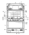
本発明の実施形態に係るスロットマシン10の外観を図1に示す。図1は、スロットマシン10の正面図であり、同図において、スロットマシン10の筐体の前面部には、フロントパネル20が設けられている。このフロントパネル20の略中央には、表示窓22が形成されており、スロットマシン10の内部に回転自在に設けられている3個のリール40L,40C及び40Rの外周面に印刷された図柄が表示される。リール40L,40C及び40Rは、各回転軸が、水平方向の同一直線上に並ぶように設けられ、各々リング状の形状を有し、その外周面には20個の図柄が等間隔で印刷された帯状のリールテープが貼り付けられている。そして、表示窓22からは、リール40L,40C及び40Rが停止しているときに、各リールに印刷された20個の図柄のうち、各リールの回転方向に沿って連続する3つの図柄が視認可能となっている。すなわち、表示窓22には、3[図柄]×3[リール]=合計9つの図柄が停止表示される。ここで、リール40L,40C及び40Rが停止しているときに表示される連続する3つの図柄のうち、最も上側の停止表示位置を上段U、中央の停止表示位置を中段M、最も下側の停止表示位置を下段Lとする。
[Description of appearance structure]
An appearance of a
また、表示窓22には、リール40L,40C及び40Rの各中段Mを横切る1本の入賞ラインLが定められている。この入賞ラインLは、予め定められた複数種類の役(後述する)に対応する図柄組合せが停止表示されたか否かを判定する際の基準となるラインである。すなわち、リール40L,40C及び40Rが停止したときに、入賞ラインLが通過する停止表示位置(各リールの中段M)に停止表示された3つの図柄からなる組合せがいずれかの役に対応していたときに、その役が入賞したことになる。なお、以下では、単に「図柄組合せが停止表示された」と記載されている場合は、その図柄組合せが入賞ラインLに沿って停止表示されたことを意味する。
The
フロントパネル20には、表示窓22の他に、単位遊技に関する各種情報を遊技者へ知らせるための各種ランプおよび表示器が設けられている。表示窓22の下側には、図1中、左から順に、ベット数(賭け枚数)表示ランプ26a,26b,26c、クレジット数表示器27、および、獲得枚数表示器28が設けられている。ベット数表示ランプ26a,26b,26cは、1回の遊技に投入されるメダルの枚数を表示するものである。すなわち、1枚のメダルが投入されるとベット数表示ランプ26aのみが点灯し、2枚のメダルが投入されるとベット数表示ランプ26aおよび26bが点灯し、3枚のメダルが投入されるとベット数表示ランプ26a,26b,26cが点灯する。
In addition to the
ここで、スロットマシン10で単位遊技を行うために投入するメダルは遊技媒体の一種であり、遊技媒体は、メダルに限らず、遊技球(いわゆるパチンコ球)や、磁気カード、非接触式ICカードまたはICチップを内蔵したコインなどの記録媒体に記録された、単位遊技を行うことができる価値情報であってもよい。スロットマシン10では、3枚のメダルが投入されると1回の単位遊技が可能となり、入賞ラインLが有効ラインとされる。クレジット数表示器27(貯留数表示手段)は、2桁の7セグメント表示器からなり、スロットマシン10にクレジット(貯留)されている(より具体的には、後述する主制御回路100内のRAMに記憶されている)メダルの枚数を表示する。獲得枚数表示器28(付与数表示手段)は、2桁の7セグメント表示器からなり、スロットマシン10において単位遊技の結果に応じて遊技者へ払い出されるメダルの枚数を表示する。
Here, a medal inserted to play a unit game in the
上述したフロントパネル20の下側には、概略水平の操作パネル部30が設けられている。操作パネル部30の上面右側には、スロットマシン10へメダルを投入するためのメダル投入口32が設けられている。このメダル投入口32の内部には、メダル投入口32から投入されたメダルを検出すると、後述する主制御回路100へメダル検出信号を出力するメダルセンサが設けられている。これにより、主制御回路100においてメダル検出信号の出力回数を計数することで、投入されたメダルの枚数を認識することができる。
A substantially horizontal
また、操作パネル部30の上面左側には、クレジットされているメダルをスロットマシン10へ投入することができる1−ベットスイッチ34および最大ベットスイッチ35が設けられている。1−ベットスイッチ34は、1回操作されるごとにクレジットされているメダルのうち1枚だけを遊技の賭けの対象としてスロットマシン10へ投入するためのスイッチである。最大ベットスイッチ35は、クレジットされているメダルのうち、現在の単位遊技において投入が許容される最大枚数(規定枚数)のメダルを、遊技の賭けの対象としてスロットマシン10へ投入するためのスイッチである。なお、スロットマシン10においては、後述するMB遊技における規定枚数は2枚であり、MB遊技ではない遊技(通常遊技)における規定枚数は3枚である。
A 1-
メダル投入口32から、または、各種ベットスイッチ34,35を操作することにより、スロットマシン10に3枚のメダルを投入すると、メダルが投入されるごとにベット数表示ランプ26a,26b,26cが順次点灯していく。また、前述した主制御回路100のRAM(貯留手段160に相当)に記憶されているクレジット数から、投入されたメダルの枚数が減算されるとともに、クレジット数表示器27に表示されている値も減算される。さらに、規定枚数のメダルが既に投入されている状態で、さらにメダル投入口32からメダルが投入されると、当該投入されたメダルの枚数が、主制御回路100のRAMに記憶されているクレジット数に加算されるとともに、クレジット数表示器27に表示されている値に加算される。
When three medals are inserted into the
操作パネル部30の正面左側には、スタートスイッチ36が傾動可能に設けられている。スタートスイッチ36は、遊技者がスロットマシン10に規定枚数のメダルを投入すると操作が有効となる。なお、単位遊技で後述する再遊技役が入賞したときは、メダルが投入されなくても、ベット数表示ランプ26a,26b,26cが規定枚数分だけ点灯し、次の単位遊技のための、スタートスイッチ36の操作が有効となる。この状態で遊技者がスタートスイッチ36を傾動操作すると、前述した3つのリール40L,40C及び40Rが一斉に回転を開始する。これにより、リール40L,40C及び40Rの各外周面に印刷された図柄は、表示窓22において上から下へと移動(スクロール)表示される。
A
操作パネル部30の正面中央部には、3つのストップスイッチ37L,37C及び37Rが設けられている。ここで、ストップスイッチ37L,37C及び37Rは、いわゆる自照式の押しボタンスイッチであり、押しボタンの部分が複数色に発光し得る構造になっている。また、左ストップスイッチ37Lは左リール40Lに対応し、中ストップスイッチ37Cは中リール40Cに対応し、右ストップスイッチ37Rは右リール40Rに対応している。なお、疑似遊技中は、ストップスイッチ37とリール40との対応関係を変更してもよい。具体的には、例えば、左ストップスイッチ37Lの操作により右リール40Rを停止させるようにする。ストップスイッチ37L,37C及び37Rは、3つのリール40L,40C及び40Rの回転速度が所定の定常回転速度(例えば、80回転/分。単に定速ともいう。)に達したときに、遊技者による操作が有効となる。ここで、各ストップスイッチの操作が無効になっているときは、各ストップスイッチの押しボタン部分における発光色が赤くなっており、定常回転速度に達して操作が有効になると、押しボタン部分の発光色は青に変化する。
Three stop switches 37L, 37C, and 37R are provided at the center of the front surface of the
そして、遊技者が左ストップスイッチ37Lを押動操作したときには、左リール40Lが停止し、中ストップスイッチ37Cを押動操作したときには、中リール40Cが停止し、右ストップスイッチ37Rを押動操作したときには、右リール40Rが停止する。このとき、3つのリール40L、40C及び40Rの各々は、各リールの外周面に描かれている図柄のうち、連続するいずれか3つの図柄の各中心位置と、表示窓22内の上段U、中段M、および、下段Lの各中央位置とが、一致するように停止制御される。ここで、図柄の中心と、停止表示位置の中央とが一致する位置を定位置といい、スロットマシン10がリールを停止させるときは、リールの各図柄が必ず定位置で停止するようなリール停止制御が行われる。
When the player pushes the
操作パネル部30の左側には、精算スイッチ38が設けられており、メダル投入の受付期間内に操作されると、クレジットされていたメダルがすべて払い戻され、クレジット数表示器27に表示されている値が「0」になる。ここで、メダル投入の受付期間は、例えば、スタートスイッチ36の操作が有効と見なされてリール40L、40C及び40Rが回転を開始してから、全てのリールが停止するまで(メダルが払い出される場合は、メダルの払い出しが終了するまで)の間とする。
A
操作パネル部30の下側には、スロットマシン10の機種名やモチーフとして採用されたキャラクタなどが描かれた下部パネル50が配設されている。下部パネル50の下方略中央には、遊技者に対してメダルを払い出すためのメダル払出口60が設けられている。例えば、リール40L、40C及び40Rが停止したときに、入賞ラインLに沿って停止表示された3つの図柄の組合せが小役に対応していた場合、スロットマシン10の内部に設置されたメダル払出装置が作動してその小役に対応した枚数のメダルが払い出される。また、メダルがクレジットされている状態で精算スイッチ38が操作されると、クレジットされていたメダルが払い出される。そして、払い出されたメダルは、メダル払出口60から排出されて受け皿61に貯留される。メダル払出口60の右側および左側には、各々、スロットマシン10内部に収納されたスピーカ64R,64L(後述する)から発せられた音を外部へ通すための透音孔62R,62Lが設けられている。
A
フロントパネル20の上方には、液晶ディスプレイパネルから構成される表示装置70が設けられている。なお、表示装置70は、上述した液晶ディスプレイパネルに限られず、画像情報や文字情報を遊技者が遊技中に視認し得る装置であれば、その他あらゆる画像表示装置を用いることが可能である。この表示装置70は、遊技履歴を表示したり、単位遊技中に表示される演出画像、役抽選の結果を報知するための演出画像、単位遊技の進行(メダル投入→スタートスイッチ36の操作→リールの回転→ストップスイッチ37L,37C,37Rの操作→全リール回転停止)に応じた演出画像等を表示したりすることができる。表示装置70の上方には、リール40L,40C,40Rが停止し、何らかの役が入賞した場合、入賞した役に応じたパターンで点滅する上部演出ランプ72が設けられている。
A
[リール図柄の説明]
次に、図2を参照して、リール40L、40C及び40Rの各外周面に貼り付けられるリールテープに印刷された図柄の配列について説明する。図2(a)に示すように、リール40L、40C及び40Rの各外周面には20個の図柄が印刷されているが、各図柄は、リールテープの長手方向において、20分割に区画された各図柄領域に1つの図柄が印刷されている。また、各図柄領域に表示される図柄の種類は、図2(b)に示すように、7種類あり、各種類に応じて種別コード(図示略)が予め定められている。スロットマシン10における図柄の種類には、数字の7を赤色で表した「7」図柄、“BAR”と標記された「BAR」図柄、水色のプラムをモチーフとした「リプレイ」図柄、黄色のベルをモチーフとした「ベル」図柄、赤いサクランボをモチーフとした「チェリー」図柄、緑色のスイカをモチーフとした「スイカ」図柄、薄いグレーの目立たない色で表され、いずれの役にも関連しない星をモチーフとした「ブランク」図柄がある。
[Description of reel design]
Next, with reference to FIG. 2, the arrangement of symbols printed on the reel tape attached to the outer peripheral surfaces of the
また、リール40L、40C及び40Rの各々に貼り付けられるリールテープの各図柄領域には、図2(a)に示すように「0」〜「19」の図柄番号が予め定められており、各図柄番号に対応する図柄の種別コードが、主制御回路100のROMに記憶されている。各リールの図柄番号および対応する種別コードは、スロットマシン10が、表示窓22の各停止表示位置(上段U、中段M、下段L)に表示された図柄を認識し、後述するリール停止制御を行う際に参照される。以下では、図柄番号および種別コードをまとめて図柄識別情報という。図2(a)に示す各リールテープは、図柄番号「0」と「1」の間を切り離して展開した状態を示し、実際にリール40L、40C及び40Rの外周面に貼り付けたときは、図柄番号「0」と「1」の図柄が連続することになる。
In addition, symbol numbers “0” to “19” are determined in advance in each symbol region of the reel tape attached to each of the
また、リール40L、40C及び40Rが回転すると、表示窓22内に表示される各リールの3つの図柄は、連続する3つの図柄番号の値が増加する方向にスクロール表示されることになる。たとえば、表示窓22の下段Lから上段Uに向かって、図柄番号「1」,「2」,「3」の図柄が表示されていた場合、それ以降、表示される図柄は、図柄番号「2」,「3」,「4」→図柄番号「3」,「4」,「5」→図柄番号「4」,「5」,「6」→……と変化する。そして、図柄番号「18」,「19」,「0」が表示されると、引き続き、図柄番号図柄番号「19」,「0」,「1」→図柄番号「0」,「1」,「2」→図柄番号「1」,「2」,「3」→……と変化していき、以下、リールが停止するまで図柄番号「0」から「19」のうち連続する3つの図柄が循環的にスクロール表示される。
When the
[制御回路の説明]
次に、図3に示す機能ブロック図を参照して、スロットマシン10の制御を行う制御回路について説明する。スロットマシン10の制御回路は、主制御回路100と副制御回路200とによって構成されており、主制御回路100は、スロットマシン10における単位遊技の制御を行い、副制御回路200は、主制御回路100から送信された情報に基づいてスロットマシン10で行われる演出の制御を行っている。なお、主制御回路100と副制御回路200との間の情報伝達は、主制御回路100から副制御回路200への一方向に限られており、副制御回路200から主制御回路100に対して何らかの情報が直接送信されることはない。
[Description of control circuit]
Next, a control circuit for controlling the
≪主制御回路の説明≫
<主制御回路およびその周辺のハードウェア構成>
主制御回路100は、CPU、ROM、RAM、および、外部と信号のやり取りを行うためのI/Oポートに加え、乱数を発生するための乱数発生器や、CPUなどが作動するためのクロック信号や割込信号を発生するクロック発生回路などによって構成されている。ここで、乱数発生器は0〜65535の数値範囲で乱数を発生している。主制御回路100には、操作手段300と、遊技情報表示手段400と、モータ駆動回路44と、インデックスセンサ46と、ホッパー駆動回路80およびメダル払出装置82と、外部集中端子基板84とが電気的に接続されている。
≪Description of main control circuit≫
<Main control circuit and peripheral hardware configuration>
The
操作手段300は、スタートスイッチ36からなる回転指示手段310と、3つのストップスイッチ37L、37C及び37Rからなる停止指示手段320と、1−ベットスイッチ34および最大ベットスイッチ35からなる投入指示手段330と、精算スイッチ38とによって構成されている。また、遊技情報表示手段400は、図1に示したベット数表示ランプ26a〜26cと、クレジット数表示器27と、獲得枚数表示器28とによって構成されている。
The operation unit 300 includes a
モータ駆動回路44は、主制御回路100から出力される励磁信号に従って、各リール用のステッピングモータ42L,42C,42Rを個々に励磁し、対応するリールを回転または停止させる。インデックスセンサ46L,46C,46Rは、リール40L,40C,40Rに各々対応して設けられており、対応するリールの基準位置に設けられているインデックスを検出すると、主制御回路100に対して基準位置信号を出力する。これにより主制御回路100は、当該基準位置から計数を開始したステッピングモータのステップ数に基づいて、リールの回転位置(換言すると、表示窓22に表示されている図柄)を認識している。各リールは336分割されており、ステッピングモータの1ステップの回転によりリール1分割が回転移動する。ホッパー駆動回路80は、メダルを払い出す際に主制御回路100から出力される駆動信号に従って、メダル払出装置82を駆動する。また、メダル払出装置82は、メダルを1枚払い出すごとに払出信号を主制御回路100に対して出力し、主制御回路100は、当該払出信号をカウントすることで、メダル払出装置82から払い出すメダルの枚数を制御する。
The
外部集中端子基板84は、スロットマシン10が現在行われている遊技に関する情報を外部へ出力する際に、それらの情報を中継する基板である。これにより、スロットマシン10が、例えばスロットマシン10に対応して別途設置されている遊技情報表示装置や、遊技場に設置されている各遊技機の遊技状態や出玉などを管理しているいわゆるホールコンピュータへ情報を送信する場合は、この外部集中端子基板84を介して行われる。ここで、スロットマシン10から外部へ送信される情報としては、単位遊技が行われる際にスロットマシン10へメダルが投入されたことを示す信号(IN信号)、単位遊技の結果、遊技者にメダルが払い出されたことを示す信号(OUT信号)、遊技状態が「MB遊技」になったことを示す信号(MB発生信号)、再遊技役が入賞したことを示す信号(RP発生信号)、スロットマシン10に異常が発生したことを示す信号(異常発生信号)、スタートスイッチ36が操作されたことを示す信号(スタート信号)、および、後述するサブボーナスが行われていることを示すサブボーナス実行信号とATが行われていることを示すAT信号を出力する。なお、サブボーナス実行信号の出力契機とAT信号の出力契機は異なるようにしてもよく、サブボーナス実行信号は表示窓上に7揃したタイミングで出力するようにし、AT信号は小役1(ベル)当選時の押し順の操作パターンに応じて出力することが考えられる。
The external concentrated
<主制御回路の機能ブロック>
次に、主制御回路100の機能ブロックについて説明する。主制御回路100は、役抽選手段110と、リール制御手段120と、特殊演出制御手段130と、入賞判定手段140と、入賞処理手段150と、貯留手段160と、外部信号出力手段170と、を含んでいる。なお、以下に説明する各手段の機能は、主制御回路100を構成するROMに記憶された制御プログラムを、CPUによって実行することで実現されるものとする。
<Functional blocks of main control circuit>
Next, functional blocks of the
<役抽選手段の説明>
役抽選手段110は、遊技者によるスタートスイッチ36の操作に応じて、主制御回路100が有する乱数発生器によって発生された乱数をサンプリングし、当該サンプリングした乱数に基づいて、予め定められた役のうちいずれか1つまたは複数の役を当選した役(当選役)とするか否かを定めるものである。スロットマシン10では、予め定められている役(本役)として、図4(a)に示す様に、MB役、再遊技役、小役1、小役2、小役3a〜3dの8種類があり、各々の役には、図4(a)に示すように各図柄組合せが対応付けられている。そして、図1に示した入賞ラインLに沿って停止表示された図柄組合せが、役抽選によって当選役に定められた役の図柄合せと一致すると、その役が入賞したことになる。
<Description of role lottery means>
The role lottery means 110 samples a random number generated by a random number generator included in the
図4(a)に示した各役について、まず、MB役は、入賞すると次の単位遊技からMB遊技が開始されることとなる役である。MB遊技中は、役抽選の結果に関係なく、全ての小役が当選状態となり、当選状態とされた小役のうち、小役1または小役2が必ず入賞するようになっている。なお、MB遊技中でない単位遊技(以下、通常遊技という)において、小役1が入賞すると5枚のメダルが払い出され、小役2が入賞すると3枚のメダルが払い出されるが、MB遊技中小役1または小役2が入賞したときは、いずれの場合も2枚のメダルしか払い出されない。そして、MB遊技中に合計で18枚のメダルが払い出されると、当該MB遊技が終了する。
For each combination shown in FIG. 4A, first, the MB combination is a combination in which the MB game is started from the next unit game when winning. During the MB game, regardless of the result of the role lottery, all the small roles are in the winning state, and among the small roles in the winning state, the
次に、再遊技役は、入賞すると次の単位遊技に限ってメダルを投入することなく再び遊技(再遊技またはリプレイともいう)を行うことができる役である。なお、上述したMB役も、この再遊技役も、それぞれの役が入賞したことによるメダルの払い出しは無い。これに対して、小役は、入賞すると予め定められていた枚数のメダルが払い出されることになる。入賞時に払い出されるメダルの枚数は、小役1は5枚(MB遊技中は2枚)、小役2は3枚(MB遊技中は2枚)、小役3a〜3dは、通常遊技中またはMB遊技中の区別無く、いずれの場合も1枚になっている。 Next, the re-playing role is a role that can be played again (also referred to as replaying or replaying) without inserting medals only for the next unit game when winning. Note that neither the above-described MB combination nor this re-playing combination is paid out of medals due to the winning of each combination. On the other hand, when a small role is won, a predetermined number of medals are paid out. The number of medals to be paid out at the time of winning a prize is 5 for small role 1 (2 during MB game), 3 for small role 2 (2 during MB game), and 3 In any case, there is only one card, regardless of the MB game.
また、図4(a)に示すように、役抽選手段110が行う役抽選では、MB役、再遊技役、小役2については、各役が個々に当選役と定められるが(単独抽選対象)、小役1および小役3a〜3dは、複数の役が同時に当選役に定められる(複合抽選対象)。すなわち、小役1および小役3a〜3dについては、各々複数の役で構成された複合A、複合B、複合Cが抽選対象となっている。そして、図4(a)中、「○」印で示すように、複合Aが当選したときは、小役1および小役3a〜3dが当選役となり、複合Bが当選したときは、小役1および小役3b〜3dが当選役となり、複合Cが当選したときは、小役1および小役3a,3c,3dが当選役となる。
Further, as shown in FIG. 4A, in the role lottery performed by the role lottery means 110, for the MB role, the replaying role, and the
一般に、役抽選の結果、何らかの役が当選した場合は、その状態は当選した役が入賞するか否かを問わず、単位遊技が終了するとクリアされる。しかしながら、MB役が当選したときは、その単位遊技でMB役を入賞させることができなくても、入賞するまで次の単位遊技以降に当選した状態が維持される。すなわち、MB役が入賞するまで、MB役を入賞させることができるチャンスが継続する。以下、MB役の当選状態が維持されている期間を、ボーナス持越中または内部中という。なお、後述するように、内部中における役抽選ではMB役が抽選対象とはされず、MB役が当選役になっているときに重ねて当選役と定められることはない。また、以下では、MB役が当選していない通常遊技が行われている状態を「非内部中」といい、MB役の当選が維持されている通常遊技が行われている状態を「内部中」という。また、単に「通常遊技中」といった場合は、特に定義がなされていなければ、「非内部中」および「内部中」の双方状態を意味する。 In general, when any winning combination is won as a result of the winning lottery, the state is cleared when the unit game ends regardless of whether or not the winning winning combination wins. However, when the MB combination is won, even if the MB combination cannot be won in the unit game, the state of winning after the next unit game is maintained until winning. In other words, until the MB combination wins, the chance of winning the MB combination continues. Hereinafter, the period in which the winning state of the MB combination is maintained is referred to as bonus carrying over or inside. In addition, as will be described later, in the role lottery in the inside, the MB role is not a lottery object, and when the MB role is a winning combination, it is not determined as a winning combination again. In the following, a state in which a normal game in which the MB combination is not won is referred to as “non-internal”, and a state in which a normal game in which the MB combination is maintained is referred to as “internal " Further, when “normally playing” is simply referred to, it means both “non-inside” and “inside” unless otherwise defined.
図4(b)は、疑似役の内容を示す図である。図4(b)に示すように、疑似役には「7」図柄が入賞ラインLに沿って疑似停止表示(後述)または仮停止表示(後述)される7揃役がある。7揃役が入賞ラインLに沿って疑似停止表示または仮停止表示されると、サブボーナス(AT)が1個ストックされる。 FIG. 4B is a diagram showing the contents of the pseudo combination. As shown in FIG. 4 (b), the pseudo-combination has a 7-combination in which a “7” symbol is displayed along the winning line L in a pseudo stop display (described later) or a temporary stop display (described later). When the 7 uniform combination is displayed as a pseudo stop or a temporary stop along the winning line L, one sub bonus (AT) is stocked.
次に、図5に示す役抽選テーブルを参照して、役抽選における各抽選対象の当選確率について説明する。図5に示す役抽選テーブルは、非内部中および内部中における各抽選対象について、主制御回路100の乱数発生器が発生する乱数値(0〜65535のいずれかの整数)のうち、当選と見なされる数値の数(以下、置数という。)を示している。なお、乱数値「0」も数値に含まれるため、乱数発生器が発生し得る乱数値の数は65536となる。よって、各抽選対象の当選確率は、対応する置数を65536で割った値となる。また、図5に示す役抽選テーブルにおいて、MB役および再遊技役の行は、破線によって上下段に分割されているが、上段は非内部中における置数、下段は内部中における置数を示している。さらに、「設定1」〜「設定6」は、スロットマシン10の内部に設けられたスイッチ等を操作することで設定されるものであり、遊技場の関係者が、スロットマシン10における各役の当選確率を変更する際に適宜設定される。以下では、「設定1」〜「設定6」の設定について言及する際には、カギ括弧を付して「設定」と記載することで、一般的な意味で用いる設定の文言と区別することにする。
Next, the winning probability of each lottery object in the winning lottery will be described with reference to the winning lottery table shown in FIG. The combination lottery table shown in FIG. 5 is regarded as winning among the random number values (any integer from 0 to 65535) generated by the random number generator of the
この図に示す役抽選テーブルでは、複合A〜Cおよび特殊複合の当選確率は、「設定1」〜「設定6」のいずれにおいても一定の値となっている。これに対して、小役2の当選確率は、「設定1」のときに最も低く、「設定」の値が大きくなるに連れて高くなっている。MB役については、非内部中は、小役2と同様に、当選確率が「設定1」のときに最も低く、設定の値が大きくなるに連れて高くなっているが、前述したように、MB役が当選して内部中になると、抽選対象から除外されるため、「設定1」〜「設定6」のいずれにおいても当選確率が「0」となる。これに対して、再遊技役は、非内部中は、「設定1」〜「設定6」のいずれにおいても同じ当選確率になっているが、内部中になると、「設定1」〜「設定6」のいずれにおいても置数が増大しており、再遊技役の当選確率が大幅に上昇している。また、「設定1」〜「設定6」の内部中における再遊技役、小役2、複合A〜Cおよび特殊複合の置数を合計すると、いずれの「設定」においても65536となる。すなわち、内部中はいずれかの役が必ず当選し、ハズレが無い状態となる。
In the combination lottery table shown in this figure, the winning probabilities of the composites A to C and the special composite are constant values in any of “setting 1” to “setting 6”. On the other hand, the winning probability of the
ここで、内部中となって再遊技役の当選確率が上昇した状態を「RT」中といい、内部中になる前(非内部中)の再遊技役の当選確率が低い状態を「非RT」中という。図6を参照して、役抽選の観点から見た遊技状態(換言すると、主制御回路100が直接的に認識し得る遊技状態)の遷移について説明すると、まず、スロットマシン10の電源投入直後、または、遊技状態をリセットした直後は、「非RT」中になっており、再遊技役の当選確率は、約1/7.30になっている。そして、この遊技状態でMB役が当選すると、「設定」による差はあるものの、再遊技役の当選確率が1/2.69〜1/2.74と大幅に上昇する「RT」中に移行する。「RT」中の状態はMB役が入賞するまで継続し、入賞ラインL上に「赤セブン−BAR−BAR」の図柄組合せが揃ってMB役が入賞すると、次の単位遊技からMB遊技が開始される。そして、「MB遊技」中に払い出されたメダルの枚数が、合計18枚を超えると、遊技状態は再び「非RT」中となる。このように、スロットマシン10では、「非RT」中、「RT」中、「MB遊技」中という3つの遊技状態を循環的に遷移している。
Here, a state in which the winning probability of the re-gamer is increased inside is referred to as “RT”, and a state in which the winning probability of the re-gamer before the internal (non-internal) is low is referred to as “non-RT”. "In the middle. Referring to FIG. 6, the transition of the gaming state (in other words, the gaming state that can be directly recognized by the main control circuit 100) from the viewpoint of the role lottery will be described. First, immediately after the
<リール制御手段の説明>
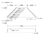
図3に戻り、リール制御手段120は、リール40L,40C,40Rの回転駆動に関する制御を行う。すなわち、遊技者によってスタートスイッチ36が操作されると、モータ駆動回路44によってステッピングモータ42L,42C,42Rの回転を開始させる。そして、リール40L,40C,40Rの回転速度を加速していき、毎分80回転の回転速度に達すると定速回転に移行し、ストップスイッチ37L,37C,37Rの操作が有効な状態にする。
<Description of reel control means>
Returning to FIG. 3, the reel control means 120 performs control related to the rotational drive of the
リール停止制御手段122は、ストップスイッチ37L,37C,37Rの操作が有効になった後、遊技者によっていずれかのストップスイッチが操作されると、操作されたストップスイッチに対応するリールの停止制御(通常停止制御)を行う。停止制御(通常停止制御)は、通常遊技中と、MB遊技中とで異なる。通常遊技中は、操作されたストップスイッチに対応するリールの回転を190ミリ秒以内に停止させる制御を行う。したがって、定速回転速度が約80回転/分であり、1つのリールに配置された図柄数が20個であるため、リール停止制御手段122は、ストップスイッチが操作された時のリール位置から、最大で約5.07図柄分だけ移動するまでの間に、リールを停止させることになる。ここで、前述したように、図柄の停止位置のばらつきを無くすため、リール上の図柄が定位置で停止表示されるように、リールを停止させなくてはならないという制約がある。このため、直ちにリールを停止させたい場合でも、ストップスイッチの操作タイミングによっては、ほぼ1図柄分、リールを回動させなくてはならない場合が生じ得る。したがって、この分の幅を考慮すると、ストップスイッチが操作されてから、最大で4図柄分リールが回動するまでの間が、停止制御可能範囲(すなわち、滑りコマ数が4)となる。 The reel stop control means 122, when any stop switch is operated by the player after the operation of the stop switches 37L, 37C, 37R becomes valid, the reel stop control means 122 corresponding to the operated stop switch ( (Normal stop control). The stop control (normal stop control) is different between the normal game and the MB game. During normal gaming, control is performed to stop the rotation of the reel corresponding to the operated stop switch within 190 milliseconds. Therefore, since the constant rotational speed is about 80 revolutions / minute and the number of symbols arranged on one reel is 20, the reel stop control means 122 determines from the reel position when the stop switch is operated, The reel is stopped until the maximum amount of movement is about 5.07 symbols. Here, as described above, there is a restriction that the reel must be stopped so that the symbols on the reel are stopped and displayed at a fixed position in order to eliminate variations in the symbol stop position. For this reason, even if it is desired to stop the reel immediately, depending on the operation timing of the stop switch, there may be a case where the reel has to be rotated by approximately one symbol. Therefore, in consideration of the width of this amount, the stop controllable range (that is, the number of sliding symbols is 4) is the time from when the stop switch is operated until the reel of four symbols is rotated at the maximum.
よって、リール停止制御手段122が引込制御を行う場合は、ストップスイッチが操作された時に、入賞ラインLから上流側にある4つの図柄のうち、当選役に対応する図柄組合せを構成する図柄があるときは、その図柄が入賞ラインL上に停止表示されるように、リールの回転を停止させる。これに対して、リール停止制御手段122が蹴飛ばし制御を行う場合は、全てのリールが停止するまでに、入賞ラインL上に何らかの役に対応した図柄組合せが停止表示されないように、リールの回転を停止させる。 Therefore, when the reel stop control means 122 performs the pull-in control, among the four symbols on the upstream side from the winning line L when the stop switch is operated, there is a symbol constituting a symbol combination corresponding to the winning combination. At that time, the rotation of the reel is stopped so that the symbol is stopped and displayed on the winning line L. On the other hand, when the reel stop control means 122 performs the kicking control, the reels are rotated so that the symbol combination corresponding to any combination is not stopped and displayed on the winning line L before all the reels stop. Stop.
一方、MB遊技中は、中ストップスイッチ37Cおよび右ストップスイッチ37Rが操作された場合は、通常遊技中と同様のリール停止制御を行うが(操作されてから190ミリ秒以内に対応するリールを停止)、左ストップスイッチ37Lについては、操作されてから75ミリ秒以内に左リール40Lの回転を停止させる制御を行う。したがって、MB遊技中においては、左ストップスイッチ37Lが操作されてから左リール40Lが最大で約2.0図柄分、回動するまでの間に停止させなくてはならない。よって、図柄を定位置で停止させるための幅を1図柄分取るとすると、停止制御可能範囲は最大で1図柄分となる。
On the other hand, during the MB game, when the middle stop switch 37C and the
また、リール停止制御手段122は、図3に示すインデックスセンサ46L,46C,46Rから出力される各基準位置信号と、モータ駆動回路44からステッピングモータ42L,42C,42Rへ各々出力される励磁信号のパターンを更新した回数(すなわち、各ステッピングモータが1ステップ分、回動した回数)とに基づいて、表示窓22に表示されている図柄を認識している。リール上の図柄の認識方法については、従来の方法が採用可能であるため、詳細な説明は省略する。
Further, the reel stop control means 122 receives reference position signals output from the
上述したリール停止制御を前提として、図2(a)に示した各リールの図柄配列と、図4(a)に示した各役に対応した図柄組合せをみると、リール40L,40C,40Rに各々配置されている「リプレイ」図柄は、最大でも4つの図柄を挟んで配置されているため、通常遊技中は、役抽選で再遊技役が当選したときは、如何なるタイミングでストップスイッチが操作されたとしても、必ず入賞させることができる。また、「ベル」図柄および左リール40Lにおける「スイカ」図柄も同様に配置されているため、通常遊技中であれば、小役1および小役2も必ず入賞させることができる。
On the premise of the reel stop control described above, the symbol arrangement of each reel shown in FIG. 2A and the symbol combination corresponding to each combination shown in FIG. 4A show the
さらに、左リール40Lにおいて、「ベル」図柄と「スイカ」図柄とは、1つの図柄を挟んで交互に配置されているため、MB遊技中であっても、遊技者による左ストップスイッチ37Lの操作タイミングに応じて小役1または小役2のいずれか一方を、必ず入賞させることができる。ここで、MB遊技中は、全ての小役が当選役とされるが、リール停止制御手段122は、左ストップスイッチ37Lの操作タイミングに応じて小役1または小役2のいずれか一方を入賞させるリール停止制御を行い、その他の小役を入賞させることはないものとする。
Further, in the
次に、図4(a)に示された小役3a〜3dの図柄組合せを見ると、通常遊技中に、左リール40Lについては「リプレイ」図柄が、中リール40Cおよび右リール40Rについては、各々、「チェリー」図柄または「スイカ」図柄のいずれか一方が、入賞ラインL上に停止表示されれば、小役3a〜3dのいずれか1つが入賞することになる。これを踏まえて図2(a)の図柄配列を見ると、通常遊技中に小役3a〜3dが当選した場合は、如何なるタイミングでストップスイッチ37L,37C,37Rを操作しても、小役3a〜3dのうちいずれか1つを入賞させることができる。
Next, looking at the symbol combinations of the small roles 3a to 3d shown in FIG. 4 (a), during the normal game, the “replay” symbol for the
ここで、図4(a)に示す様に、複合A〜複合Cが当選したときに、小役1およびいずれかの小役3a〜3dが同時に当選することになる。このとき、リール停止制御手段122は、複合Aが当選した時は、ストップスイッチ37L,37C,37Rが左→中→右または左→右→中の順序で操作されたときに、小役1を入賞させ、それ以外の順序でストップスイッチが操作された時は、そのタイミングに応じて小役3a〜3dのいずれか1つを入賞させるリール停止制御を行う。また、複合Bが当選した時は、ストップスイッチ37L,37C,37Rが中→左→右または中→右→左の順序で操作されたときに、小役1を入賞させ、それ以外の順序でストップスイッチが操作された時は、そのタイミングに応じて小役3b〜3dのいずれか1つを入賞させるリール停止制御を行う。さらに、複合Cが当選した時は、ストップスイッチ37L,37C,37Rが右→左→中または右→中→左の順序で操作されたときに、小役1を入賞させ、それ以外の順序でストップスイッチが操作された時は、そのタイミングに応じて小役3a、3c、3dのいずれか1つを入賞させるリール停止制御を行う。
Here, as shown in FIG. 4A, when the composite A to the composite C are won, the
このように、リール停止制御手段122は、複合A〜複合Cのいずれかが当選したときは、ストップスイッチ37L,37C,37Rの操作順序に応じて入賞させる小役を変更している。なお、上述したリール停止制御では、最初に操作されたストップスイッチの種類に応じて入賞させる小役を変更していたが(いわゆる3択のAT)、さらに複合抽選対象を増やして、最初から最後までのストップスイッチの操作順序(すなわち、6通りの操作順序)について、小役1が入賞することとなる操作順序を個々に異ならせても良い(いわゆる6択のAT)。また、左ストップスイッチ37L以外が第1停止操作されるとペナルティが科されるようにして、AT中には、第1停止操作が左ストップスイッチ37L以外のいずれかの操作順序で停止操作されると小役1が入賞するようにしてもよい(4択のAT)。
As described above, when any one of the composite A to composite C is won, the reel stop control means 122 changes the small part to be awarded according to the operation order of the stop switches 37L, 37C, 37R. In the reel stop control described above, the winning combination is changed according to the type of the first operated stop switch (so-called three-choice AT). With respect to the operation sequence of the stop switches up to the above (that is, six operation sequences), the operation sequence in which the
さらに、内部中はMB役が当選した状態が維持されることから、MB役と、小役または再遊技役とが、同時に当選した状態となる。この場合、リール停止制御手段122は、再遊技役または小役を優先的に入賞させるリール停止制御を行う。 Furthermore, since the state in which the MB combination is won is maintained inside, the MB combination and the small combination or re-playing combination are simultaneously selected. In this case, the reel stop control means 122 performs reel stop control for preferentially winning a re-game combination or a small combination.
なお、図5に示す役抽選テーブルには、ハズレが無いが、例えば、ハズレに対応する置数を1として役抽選テーブルにハズレを設け、ハズレが抽選されたときにMB役が入賞するようにしてもよい。また、役抽選テーブルに取りこぼしのある小役を設け、その小役を取りこぼしたときに、MB役が入賞するようにしてもよい。
ここで、取りこぼしとは、当選役に対応する図柄を揃えることができず、当選役に対応する特典を獲得できずにその特典が消滅してしまうことをいう。取りこぼしには、当選した役に対応する図柄の組み合わせを引き込みできなかったことによる取りこぼしと、入賞するために操作順序が定められた小役が定められた操作順序で操作されなかったことにより入賞しなかったときの取りこぼしと、がある。
Although there is no losing in the role lottery table shown in FIG. 5, for example, a number corresponding to the losing is set to 1 and a losing is provided in the role lottery table so that the MB character wins when the losing is lottery. May be. In addition, a small combination with a missing part may be provided in the combination lottery table, and the MB combination may be awarded when the small combination is missed.
Here, “missing” means that the symbol corresponding to the winning combination cannot be prepared, and the privilege corresponding to the winning combination cannot be acquired and the privilege disappears. The winning combination will be a winning because the combination of symbols corresponding to the winning combination could not be pulled in, and a small role whose operating order was determined to win a prize was not operated in the specified operating order. There is a loss when there was no.
<通常停止テーブルの説明>
通常停止テーブルは、ストップスイッチ37が操作されたときのリール40の図柄番号に応じたリール40の停止位置に関する情報を定めたものであり、具体的には、ストップスイッチ37が操作された時点のリール40の図柄番号に応じて、リール40の図柄位置から移動可能な最大移動可能図柄数(最大スベリコマ数、4コマ)の範囲におけるいずれの位置でリール40を停止させるかを定めたものである。通常停止テーブルは、役に応じて対応する通常停止テーブルが選択される。
換言すれば、通常停止テーブルにおいては、リール40の図柄が中段ラインLに位置しているときを基準の図柄番号として、この基準の図柄番号から移動可能なコマ数(0コマから4コマまで)の範囲内のいずれかの図柄番号が停止位置として定められている。
<Description of normal stop table>
The normal stop table defines information related to the stop position of the
In other words, in the normal stop table, when the symbol of the
図7は、役抽選手段110による役抽選によって、小役2(スイカ)が当選したときに選択される通常停止テーブルである。図7(a)は、停止操作を受け付けた時点の図柄番号とリール40を停止させるまでの滑りコマ数との対応関係を示す図である。小役2(スイカ)が当選すると、リール40L、40C、40R各々に対応する通常停止テーブルが選択される。例えば、左リール40Lの図柄番号10の図柄「7」が中段ラインLに位置しているときに、左ストップスイッチ37Lの停止操作が受け付けられると、2コマ滑って図柄番号12の図柄「スイカ」が中段ラインLに停止されることを示す(図7(b)参照)。
FIG. 7 is a normal stop table selected when the small combination 2 (watermelon) is won by the combination lottery by the combination lottery means 110. FIG. 7A is a diagram showing a correspondence relationship between the symbol number when the stop operation is received and the number of sliding symbols until the
同様に、中リール40Cの図柄番号10の図柄「7」が中段ラインLに位置しているときに、中ストップスイッチ37Cの停止操作が受け付けられると、3コマ滑って図柄番号13の図柄「スイカ」が中段ラインLに停止されることを示す(図7(c)参照)。
また、右リール40Rの図柄番号10の図柄「7」が中段ラインLに位置しているときに、右ストップスイッチ37Rの停止操作が受け付けられると、3コマ滑って図柄番号13の図柄「スイカ」が中段ラインLに停止されることを示す(図7(d)参照)。
Similarly, when the stop operation of the
Further, when the stop operation of the
<疑似役停止テーブルの説明>
疑似役停止テーブルは、ストップスイッチ37が操作されたときのリール40の図柄番号に応じたリール40の疑似停止位置に関する情報を定めたものであり、後述する疑似役に応じて対応する疑似役停止テーブルが選択される。より具体的には、ストップスイッチ37が操作された時点のリール40の図柄番号に応じて、リール40の図柄位置から移動可能な最大移動可能図柄数(最大スベリコマ数、19コマ)の範囲におけるいずれの位置でリール40を停止させるかを定めたものである。
<Description of pseudo role stop table>
The pseudo role stop table defines information related to the pseudo stop position of the
図8は、7揃役の疑似停止が決定されたときに選択される疑似役停止テーブルである。図8(a)は、停止操作を受け付けた時点の図柄番号とリール40を停止させるまでの滑りコマ数との対応関係を示す図である。7揃役の疑似停止が決定されると、リール40L、40C、40R各々に対応する疑似役停止テーブルが選択される。例えば、右リール40Rの図柄番号5の図柄「ベル」が中段ラインLに位置しているときに、右ストップスイッチ37Rの停止操作が受け付けられると、5コマ滑って図柄番号10の図柄「7」が中段ラインLに停止されることを示す(図8(b)参照)。
FIG. 8 is a pseudo-combination stop table that is selected when it is determined that the 7-part combination pseudo-stop is determined. FIG. 8A is a diagram showing a correspondence relationship between the symbol number at the time when the stop operation is accepted and the number of sliding symbols until the
同様に、中リール40Cの図柄番号5の図柄「ブランク」が中段ラインLに位置しているときに、中ストップスイッチ37Cの停止操作が受け付けられると、5コマ滑って図柄番号10の図柄「7」が中段ラインLに停止されることを示す(図8(c)参照)。
また、左リール40Lの図柄番号5の図柄「ベル」が中段ラインLに位置しているときに、左ストップスイッチ37Lの停止操作が受け付けられると、5コマ滑って図柄番号10の図柄「7」が中段ラインLに停止されることを示す(図8(d)参照)。
Similarly, when the stop operation of the
Also, when the symbol “Bell” of
なお、疑似役停止テーブルは、後述するフリーズ演出中における、リール演出または疑似遊技において使用される。疑似役停止テーブルには、リール40が順方向(図1に示した表示窓22内において、図柄が上方から下方へ移動する方向)に回転して7揃が成立するテーブルと、7揃が成立しないテーブルと、後述する特殊演出Eで使用される左リール40Lにおいて図柄「7」が中段ラインLより半図柄上方向に離れた位置に仮停止表示、中リール40Cにおいて図柄「7」が中段ラインLに仮停止表示、右リール40Rにおいて図柄「7」が中段ラインLより半図柄下方向に離れた位置に仮停止表示されるテーブル(詳細は後述)と、リール40が順方向または順方向と逆方向に回転して7揃が成立するテーブルと、がある。
The pseudo combination stop table is used in a reel production or a pseudo game during a freeze production described later. The pseudo combination stop table is a table in which the
なお、リール演出または疑似遊技では、上述した疑似役停止テーブルを使用しなくてもよい。疑似役停止テーブルを使用しないときは、現在図柄が停止している位置から、図柄が仮停止または疑似停止する位置までの距離を演算し、演算した距離分だけ図柄を移動させる。疑似役停止テーブルを使用することなく距離に基づき図柄を移動させることにより、テーブルが不要となるため、主制御回路100の記憶容量が不足することを防げる。
In the reel production or the pseudo game, the pseudo combination stop table described above may not be used. When the pseudo combination stop table is not used, the distance from the position where the symbol is currently stopped to the position where the symbol is temporarily stopped or pseudo-stopped is calculated, and the symbol is moved by the calculated distance. By moving the symbol based on the distance without using the pseudo role stop table, the table becomes unnecessary, so that the storage capacity of the
また、リール演出または疑似遊技では、上述した疑似役停止テーブルの代りにビットテーブルを使用してもよい。図29は、左リール40Lにおいて図柄「スイカ」が停止表示されるビットテーブルを示す。ビットテーブルは、リール40の各図柄位置に対応してそれぞれ8ビットのデータ領域を有する。そして、ビットテーブルは、リール40の20個の図柄がそれぞれ中段にあるときの位置が、停止不可位置(0を記憶)であるか又は停止可能位置(1を記憶)であるかを定める。
In the reel production or the pseudo game, a bit table may be used instead of the pseudo role stop table described above. FIG. 29 shows a bit table in which the symbol “watermelon” is stopped and displayed on the
各8ビットのデータ領域は、最上位ビット(左端のビット)を「はずれ」とし、最上位ビットから1つ隣のビットを「再遊技役」に対応させ、最上位ビットから2つ隣のビットを「小役2」に対応させ、最上位ビットから3つ隣のビットを「複合A」に対応させ、最上位ビットから4つ隣のビットを「複合B」に対応させ、最上位ビットから5つ隣のビットを「複合C」に対応させ、最上位ビットから6つ隣のビットを「MB」に対応させておく。 In each 8-bit data area, the most significant bit (leftmost bit) is set to “out”, the bit next to the most significant bit is made to correspond to “replaying role”, and the next two bits from the most significant bit. Is associated with “composite 2”, 3 bits from the most significant bit are associated with “Composite A”, 4 bits from the most significant bit are associated with “Composite B”, and from the most significant bit. The 5 adjacent bits are associated with “Composite C”, and the 6 adjacent bits from the most significant bit are associated with “MB”.
役抽選手段110による抽選の結果に基づき、リール40の位置が、停止させてはいけない停止不可位置(たとえば、小役2に当選していないにもかかわらず、左リール40Lにおいて図柄「スイカ」が停止表示されてしまう位置)であると判断される場合には、左リール40Lの位置に対応するデータ領域における最下位ビットを「0」とする。
Based on the result of the lottery by the part lottery means 110, the position of the
例えば、小役2に当選しており、左リール40Lの位置が図柄「スイカ」を停止表示可能な位置である場合には、左リール40Lにおいて図柄「スイカ」がある図柄番号3、7、12、16、0に対応するデータ領域は「00100001」となる。
For example, when the
ビットテーブルは、当選役に基づき、データ領域の値を0または1に書き換えるだけでよいので、停止テーブルを複数有する場合に比べて、主制御回路100の記憶容量が不足することを防げる。
Since the bit table only needs to rewrite the value of the data area to 0 or 1 based on the winning combination, it is possible to prevent the storage capacity of the
リール演出または疑似遊技では、上記の通常時に使用されるビットテーブル、例えば小役2に対応するビットテーブルを使用する。そのとき、上述のように、図柄番号3、7、12、16、0に対応するデータ領域は「00100001」となっている。そして、リール演出または疑似遊技において7揃役が決定されているときには、図柄「7」がある図柄番号10に対応するデータ領域を「00100001」、図柄番号1〜9、11〜0に対応するデータ領域を「00000000」に書き換える処理を行う。
In the reel effect or the pseudo game, the bit table used in the normal time, for example, the bit table corresponding to the
図29は、小役2(スイカ)当選時左第1停止時のビットテーブルとなっているが、他にも中第1停止時、右第1停止時、中第2停止時のようにストップスイッチ36の操作通りのビットテーブルが作成されるがここでは省略する。また、図29は、小役2(スイカ)当選時のビットテーブルとなっているが、はずれ、再遊技役、複合A、複合B、複合C,MB当選時ごとに、ストップスイッチ36の操作に応じて左、中、右第1停止時、左、中、右第2停止時、左、中、右第3停止時、のビットテーブルを作成する。
<フリーズ演出の説明>
FIG. 29 is a bit table at the time of the first stop at the left when the small role 2 (watermelon) is won, but it is also stopped at the time of the middle first stop, the right first stop, the middle second stop, etc. A bit table according to the operation of the
<Explanation of freeze production>
遊技の進行を所定期間一時停止状態にして遅延させる「フリーズ演出」としては、例えば、遊技媒体の受付け、予めクレジットされた遊技媒体の賭け枚数を定めるためのベットスイッチ35の操作の受付け、遊技を開始するためのスタートスイッチ36の操作の受付け、又は、リールの停止操作の受付けに関する機能を一時停止状態にすることが挙げられる。
Examples of the “freeze effect” in which the progress of the game is paused and delayed for a predetermined period include, for example, accepting game media, accepting an operation of the
フリーズ演出としては、前述した遊技の進行に関わる全ての機能に関して一時停止状態にしてもよいし、一部の機能に関してのみ一時停止状態にしてもよい。 As the freeze effect, all the functions related to the progress of the game described above may be paused, or only some functions may be paused.
遊技の進行を一時停止状態にする態様としては、遊技者の操作に基づく制御処理(通過センサによる遊技媒体の投入検出処理、ベットスイッチ35の操作に基づいた賭け枚数設定処理、スタートスイッチ36の操作に基づいたリール回転処理または役抽選処理、リール停止スイッチの操作に基づいたリール停止処理)を行わないことが挙げられる。
As a mode in which the progress of the game is paused, a control process based on the player's operation (game medium insertion detection process by the passage sensor, a bet number setting process based on the operation of the
フリーズ演出によって遊技の進行を一時停止している期間中に遊技者の操作に基づいた入力信号が発せられたときは、入力信号に基づく制御処理を行わない、入力信号を受付けない、入力信号の送信を所定期間が経過するまで遅延させるなどの処理を行うことで、フリーズ演出を行わない場合と比べ1回の遊技における終了タイミングが遅延することになる。 When an input signal based on the player's operation is issued during a period in which the progress of the game is paused due to the freeze effect, control processing based on the input signal is not performed, the input signal is not accepted, the input signal By performing processing such as delaying transmission until a predetermined period elapses, the end timing of one game is delayed as compared with the case where the freeze effect is not performed.
スタートスイッチ36の操作に基づいて行われるフリーズ演出に関しては、スタートスイッチ36が操作されたときに所定期間はリールの回転を行わずに所定期間の経過後にリールの回転を行う場合や、スタートスイッチ36が操作されたときに所定期間は役抽選とリールの回転を行わずに所定期間の経過後に役抽選とリールの回転を行う場合や、スタートスイッチ36が操作されたときに所定期間は役抽選を行うがリールの回転は行わずに所定期間の経過後にリールの回転を行う場合や、スタートスイッチ36が操作されて役抽選が行われた後に所定期間を設定し所定期間中はリールの回転や停止を行う場合が挙げられる。
Regarding the freeze effect performed based on the operation of the
ストップスイッチ37の操作に基づいて行われるフリーズ演出に関しては、ストップスイッチ37の操作の受付けに基づいて行うフリーズ演出とストップスイッチ37の操作の結果、特定の図柄がリール上に停止表示されたことに基づいて行うフリーズ演出において、フリーズ演出の制御処理が異なる。 With respect to the freeze effect performed based on the operation of the stop switch 37, a specific symbol is stopped and displayed on the reel as a result of the freeze effect performed based on the acceptance of the operation of the stop switch 37 and the operation of the stop switch 37. In the freeze effect performed based on the control process of the freeze effect.
ストップスイッチ37の操作の受付けに基づいて行うフリーズ演出の制御処理は、回転しているリールの停止制御処理を行わないことが挙げられる。これにより所定期間においては、遊技者が回転しているリールを停止できなくなるが、所定期間が経過したことによりストップスイッチ37の操作の受付け処理より後の停止制御処理を行うので、停止受付けからリール停止までのタイミングを遅延させることができる。 The freeze effect control process performed based on the acceptance of the operation of the stop switch 37 includes not performing the stop control process of the rotating reel. As a result, the player cannot stop the rotating reel for a predetermined period, but since the stop control process after the operation reception process for the stop switch 37 is performed after the predetermined period has elapsed, The timing until the stop can be delayed.
ストップスイッチ37の操作の結果、特定の図柄がリール上に停止表示されたことに基づいて行うフリーズ演出の制御処理は、最後のストップスイッチ37以外のストップスイッチ37の操作で特定の図柄がリール上に停止表示されたときは、次に停止するストップスイッチ37の停止制御を行わず、最後のストップスイッチ37の操作で特定の図柄がリール上に停止表示されたときは、次の遊技を開始するベットスイッチ35の操作に基づいた賭け枚数設定処理、通過センサによる遊技媒体の投入検出処理、または、リプレイが有効ライン上に停止したときに行う自動賭け枚数設定処理に基づく制御処理を行わないことが挙げられる。
<リール演出の説明>
As a result of the operation of the stop switch 37, the freeze effect control processing performed based on the fact that the specific symbol is stopped and displayed on the reel is performed by operating the stop switch 37 other than the last stop switch 37. When the stop display is stopped, the stop control of the stop switch 37 to be stopped next is not performed, and when a specific symbol is stopped and displayed on the reel by the last operation of the stop switch 37, the next game is started. The betting number setting process based on the operation of the
<Description of reel production>
フリーズ演出を行う所定期間は、遊技者の操作に基づく遊技進行制御を一時停止させるが、遊技の進行に関わらない遊技機動作は実行可能である。例えば、ストップスイッチ37の操作に基づく停止制御処理は行わないが、リールの回転態様は任意に設定することができる。 During the predetermined period of performing the freeze effect, the game progress control based on the player's operation is temporarily stopped, but the gaming machine operation that is not related to the progress of the game can be executed. For example, the stop control process based on the operation of the stop switch 37 is not performed, but the reel rotation mode can be set arbitrarily.
所定期間におけるリールの回転態様(以下リール演出と称する)として、リールを通常回転とは逆方向に回転すること、リールを所定図柄数回転し特定の図柄組合せを停止(以下リール演出中の停止を仮停止と称する)すること、複数のリールのうち所定のリールを停止状態にして他のリールを回転状態にすること、リールの回転速度を変化すること、または、遊技者の操作に起因してリールの動作を変化することが挙げられる。 As a rotation mode of the reel in a predetermined period (hereinafter referred to as a reel effect), the reel is rotated in the opposite direction to the normal rotation, the reel is rotated a predetermined number of symbols, and a specific symbol combination is stopped (hereinafter, the stop during the reel effect is stopped). Caused by a temporary stop), a predetermined reel among a plurality of reels being stopped and another reel being rotated, a rotation speed of the reel being changed, or a player's operation For example, changing the operation of the reel.
リール演出においては、所定の図柄を移動前位置から基準位置に移動して仮停止させる特定リール制御が行われる。特定リール制御では前述した疑似役停止テーブルが使用される。 In the reel effect, specific reel control is performed in which a predetermined symbol is moved from the pre-movement position to the reference position and temporarily stopped. In the specific reel control, the above-described pseudo combination stop table is used.
フリーズ演出を行う所定期間は、所定の条件(遊技者の操作、抽選等)によって変化させることができる。ここで、所定の条件とは、遊技者による操作(スタートスイッチ36、ベットスイッチ35、ストップスイッチ37、清算スイッチ38)に基づく信号の検出や抽選による所定の結果が挙げられる。また、変化させることとは一時停止期間を短くすることや長くすることが挙げられる。
The predetermined period during which the freeze effect is performed can be changed according to predetermined conditions (player operation, lottery, etc.). Here, the predetermined condition includes detection of a signal based on an operation by the player (start
一時停止期間を短くする制御処理として、一時停止期間を強制終了すること、または、一時停止期間よりも短い期間に書き換えることが挙げられる。そして、一時停止期間を長くする制御処理として、一時停止期間の後に他の期間を追加すること、または、一時停止期間よりも長い期間に書き換えることが挙げられる。また、フリーズ演出に基づく一時停止期間は、最大時間が定められたものでなく、遊技者の操作に基づき一定の結果が得られるまで継続してもよい。 Control processing for shortening the temporary stop period includes forcibly terminating the temporary stop period or rewriting it to a period shorter than the temporary stop period. And as a control process which lengthens a pause period, adding another period after a pause period, or rewriting to a period longer than a pause period is mentioned. In addition, the pause period based on the freeze effect is not set for the maximum time, and may be continued until a certain result is obtained based on the player's operation.
フリーズ演出を行う一時停止期間は、ウエイト期間の経過後に設定してもよいし、ウエイト期間を含んで設定してもよい。ウエイト期間を含んだ場合は、ウエイト期間中にフリーズ演出が終了するか否かを判断して、終了する場合は、ウエイト期間後にフリーズ演出期間を設定する態様やフリーズ演出終了後に残りのウエイト期間を再開する態様が挙げられる。または、予めウエイト期間よりも長い期間のフリーズ演出期間を設けることで、このような判断処理を省略することも可能である。
<疑似遊技の説明>
The pause period during which the freeze effect is performed may be set after the wait period has elapsed, or may be set including the wait period. When the wait period is included, it is determined whether the freeze effect ends during the wait period, and when it is ended, the mode for setting the freeze effect period after the wait period or the remaining wait period after the freeze effect ends. The aspect which restarts is mentioned. Alternatively, it is possible to omit such a determination process by providing a freeze effect period longer than the wait period.
<Description of pseudo game>
フリーズ演出として、あたかも通常の遊技を進行しているかのような疑似遊技フリーズ演出(以下疑似遊技と称する)を行うことが挙げられる。疑似遊技フリーズ演出(疑似遊技)は、スタートスイッチ36が操作されたことに基づいたスタートスイッチ受付け処理からリール回転開始処理までの間にフリーズ演出期間を定め、フリーズ演出期間中は、通常の遊技のようにスタートスイッチ36の操作に基づいてリール回転制御を行い、ストップスイッチ37の操作に基づいてリールを停止(以下疑似遊技中の停止を疑似停止と称する)する。但し、スタートスイッチ36の操作に基づく役抽選処理やストップスイッチ37の操作に基づく入賞判定処理または払出し制御処理は行わない。
As a freeze effect, performing a pseudo game freeze effect (hereinafter referred to as a “pseudo game”) as if a normal game is in progress. In the pseudo game freeze effect (pseudo game), a freeze effect period is defined between the start switch receiving process and the reel rotation start process based on the operation of the
疑似遊技フリーズ演出(疑似遊技)では、ストップスイッチ37が操作されたタイミング、特定のリールが回転したタイミング、又は、全てのリールが停止したタイミングで疑似停止したリール40が上下に揺動する動きを行う。なお、疑似遊技において、ストップスイッチ37が操作されることなく、所定時間が経過したとき、リール40を自動停止し図柄が疑似停止表示されるようにしてもよい。そして、疑似停止(以下疑似停止表示ともいう)とは、疑似演出中に、リール40が500ms以内の停止時間で一時停止した第1の停止位置と、500ms以内の停止時間で一時停止した第1の停止位置と異なる第2の停止位置との間を、揺動している停止状態である。第1の停止位置と第2の停止位置との間の角度は、リール中心において1/336度(1図柄の1/16または1/17の距離に相当)であることが望ましい。このように、疑似停止の揺動は微小であるが、遊技者が通常停止と疑似停止との区別をすることが可能となっている。なお、疑似停止は、上述した第1の停止位置と第2の停止位置との間の揺動に限らず、3箇所以上の位置間を揺動する停止状態としてもよい。これにより、通常の遊技であるか疑似遊技フリーズ演出(疑似遊技)であるかを示唆することができる。
In the pseudo game freeze effect (pseudo game), the
<特殊演出の説明>
図3に戻り、リール制御手段120は、非内部中または内部中の単位遊技において、疑似遊技の開始が決定されるとスタートスイッチ36の操作によって、リール40L,40C,40Rを回転させ、ストップスイッチ37L,37C,37Rの操作に応じて対応するリールの回転を停止させる疑似遊技とリールを所定図柄数回転し特定の図柄組合せを仮停止するリール演出との組み合わせからなる特殊演出を行う。疑似遊技とリール演出との組み合わせからなる特殊演出は、後述するように組み合わせが異なる特殊演出A〜F(図9(a)参照)の6種類がある。なお、特殊演出中は、入賞判定(入賞ラインL上に疑似停止表示または仮停止表示された図柄組合せが何らかの役に対応しているか否かの判定)を行わない、または、入賞判定を行う場合であっても、何らの役が入賞しても、その入賞を無効として扱う。このため、特殊演出中に疑似停止表示または仮停止表示された図柄組合せが、たとえ何らかの役に対応する図柄組合せと一致していたとしても、その役が入賞したことによる特典が遊技者に付与されることはない。
<Explanation of special effects>
Returning to FIG. 3, the reel control means 120 rotates the
<特殊演出制御手段の説明>
特殊演出制御手段130は、非内部中または内部中の単位遊技において、特殊演出を開始させるか否か、および、特殊演出A〜Fのいずれかを行うかの決定を行う。
図9(a)は、特殊演出の内容を示す図である。特殊演出制御手段130は、所定の乱数抽選に基づき、特殊演出を特殊演出A〜Fで開始することを、各々1/216の確率で決定し、合計1/36の確率で特殊演出の開始を決定する。
<Description of special effect control means>
The special
FIG. 9A shows the content of the special effect. The special effect control means 130 decides to start the special effects with special effects A to F based on a predetermined random number lottery with a probability of 1/216, respectively, and starts the special effects with a total probability of 1/36. decide.
特殊演出Aが決定されると、特殊演出番号PDとしてAが設定される。特殊演出Aにおいては、7揃が疑似停止表示されない疑似遊技が1回行われる。特殊演出Bが決定されると、特殊演出番号PDとしてBが設定される。特殊演出Bにおいては、7揃が疑似停止表示される疑似遊技が1回行われる。なお、目的の図柄が必ず疑似停止表示される疑似役停止テーブルの代りに、通常遊技で使用されるような4図柄滑り以内で目的の図柄が引き込めるときに目的の図柄を疑似停止するような停止テーブルを使用して疑似遊技を行ってもよい。このとき、目的の図柄を引き込めないとき、はずれの組み合わせを疑似停止して、リール40を揺動してもよい。
When the special effect A is determined, A is set as the special effect number PD. In the special effect A, a pseudo game in which seven sets are not pseudo-stop displayed is performed once. When the special effect B is determined, B is set as the special effect number PD. In the special effect B, a pseudo game in which 7 sets are pseudo-stopped is performed once. Instead of the pseudo role stop table in which the target symbol is always displayed as a pseudo stop, the target symbol is pseudo stopped when the target symbol is retracted within 4 symbol slips as used in normal games. You may play a pseudo game using a stop table. At this time, when the target symbol cannot be pulled in, the
特殊演出Cが決定されると、特殊演出番号PDとしてCが設定される。特殊演出Cにおいては、7揃が仮停止表示されるリール演出が1回行われ、その後7揃が疑似停止表示されない疑似遊技が1回行われる。
また、特殊演出Dが決定されると、特殊演出番号PDとしてDが設定される。特殊演出Dにおいては、7揃が疑似停止表示されない疑似遊技が1回行われ、その後7揃が仮停止表示されるリール演出が1回行われ、その後7揃が疑似停止表示される疑似遊技が1回行われる。
When the special effect C is determined, C is set as the special effect number PD. In the special effect C, a reel effect in which the 7 assortments are temporarily stopped is displayed once, and then a pseudo game in which the 7 assortments are not displayed in a pseudo stop is performed once.
When the special effect D is determined, D is set as the special effect number PD. In the special effect D, a pseudo game in which 7 assortments are not displayed in a pseudo stop is performed once, then a reel effect in which 7 assortments are temporarily stopped and displayed is performed once, and then a pseudo game in which 7 assortments are displayed as a pseudo stop is displayed. It is done once.
なお、7揃は、特殊演出毎に異なる確率で発生してもよい。例えば、7揃は、特殊演出Aにおける疑似遊技では30%の確率で発生し、特殊演出Bにおける疑似遊技では80%の確率で発生するように、特殊演出Cにおける疑似遊技では30%の確率で発生し、特殊演出Dにおける2回目の疑似遊技では80%の確率で発生するように、特殊演出の種類によって7揃の期待度が異なるようする。この場合、後述するように7揃の期待度に応じて、図柄の揺動幅を変更する演出が行われる。具体的には、特殊演出Aおよび特殊演出Cにおける疑似遊技では図柄の揺動幅が小さく(小揺動)、特殊演出Bおよび特殊演出Dにおける疑似遊技では図柄の揺動幅が大きくなる(大揺動)。 Note that seven assortments may occur at different probabilities for each special effect. For example, 7 assortments occur with a probability of 30% in the pseudo game in the special effect A, and with a probability of 80% in the pseudo game in the special effect B, and with a probability of 30% in the pseudo game in the special effect C. The expectation of 7 assortments is made different depending on the type of the special effect so that it occurs with a probability of 80% in the second pseudo game in the special effect D. In this case, as will be described later, an effect of changing the rocking width of the symbol is performed in accordance with the expectation of 7 assortments. Specifically, in the pseudo game in the special effect A and the special effect C, the swing width of the symbol is small (small swing), and in the pseudo game in the special effect B and the special effect D, the swing width of the symbol is large (large Rocking).
特殊演出Eが決定されると、特殊演出番号PDとしてEが設定される。特殊演出Eにおいては、図柄「7」が中段ラインLから半図柄ずれて右下がりに揃って仮停止表示されるリール演出(左リール40Lの図柄「7」が中段ラインLから半図柄上、中リール40Cの図柄「7」が中段ラインL上、右リール40Rの図柄「7」が中段ラインLから半図柄下に停止)が1回行われ、その後7揃が疑似停止表示されない疑似遊技が1回行われる。
特殊演出Fが決定されると、特殊演出番号PDとしてFが設定される。特殊演出Fにおいては、リール40が順方向または順方向とは逆方向に回転して7揃が成立するリール演出が1回行われ、その後7揃が疑似停止表示されない疑似遊技が1回行われる。
When the special effect E is determined, E is set as the special effect number PD. In the special effect E, the reel effect (the symbol “7” of the
When the special effect F is determined, F is set as the special effect number PD. In the special effect F, the
また、特殊演出制御手段130は、遊技機の遊技状態を判断可能とするフラグAと、リール毎のリールの状態(遊技状態)を判断可能とするフラグBと、に基づき各リール40の揺動状態を制御する。フラグAとフラグBの状態は、主制御回路100内のRAMに記憶される。
Further, the special effect control means 130 swings each
図9(b)は、フラグAとフラグBの内容を示す図である。フラグAが1の遊技状態は、通常遊技が行われている通常遊技状態であることを示し、フラグAが2の遊技状態は、疑似遊技が行われている疑似遊技状態であることを示し、フラグAが3の遊技状態は、リール演出が行われているリール演出状態であることを示す。 FIG. 9B shows the contents of flag A and flag B. A gaming state with a flag A of 1 indicates a normal gaming state in which a normal game is performed, a gaming state with a flag A of 2 indicates a pseudo gaming state in which a pseudo game is being performed, A game state in which the flag A is 3 indicates a reel effect state in which a reel effect is being performed.
フラグBには、左リール40Lの揺動状態を示すフラグBL、中リール40Cの揺動状態を示すBC、右リール40Rの揺動状態を示すBRがある。フラグBが1の遊技状態は、通常遊技が行われている通常遊技状態であることを示し、フラグBが2の遊技状態は、疑似遊技が行われている疑似遊技状態であることを示し、フラグBが3の遊技状態は、リール演出が行われているリール演出状態であることを示す。
The flag B includes a flag BL indicating a swinging state of the
<入賞判定手段の説明>
図3に戻り、入賞判定手段140は、遊技状態制御手段142を有し、リール40L,40C,40Rがすべて停止すると、入賞ラインL上に停止表示された図柄組合せが、何らかの役に対応するか否か(すなわち、何らかの役が入賞したか否か)を判定する。また、その判定結果に基づいて、遊技状態制御手段142に遊技状態の移行制御を行わせる。ここで、入賞判定手段140は、入賞ラインL上に停止表示された図柄組合せを直接認識しなくともよく、各リールにおいて、予め定められた位置(例えば、各リールの下段Uや、各リールの表示窓22の枠上など)の図柄を認識することで、間接的に入賞ラインL上に停止表示された図柄組合せを判断しても良い。また、入賞判定後に、小役または再遊技役の当選状態(MB役の当選状態を除く)を非当選状態にし、当選していたMB役が入賞したときに、MB役の当選状態を非当選状態にする。
<Explanation of winning determination means>
Returning to FIG. 3, the winning determination means 140 has the gaming state control means 142, and if all of the
通常遊技が行われる通常遊技状態には、「非内部中」(「非RT」中)と「内部中」(「RT」中)とがある。遊技状態制御手段142は、図6の遷移図に示すように、遊技状態が「非内部中」(「非RT」中)のときにMB役が当選すると、遊技状態を「内部中」(「RT」中)に移行させる。また、「内部中」にMB役が入賞すると、遊技状態を「MB遊技」中に移行させる。さらに、MB遊技の終了条件が成立したか否かを判断し、成立したと判断したときは、遊技状態を「非内部中」に移行させる。
The normal game state in which the normal game is performed includes “not in-inside” (in “non-RT”) and “inside in” (“RT”). As shown in the transition diagram of FIG. 6, the gaming
<入賞処理手段の説明>
入賞処理手段150は、入賞判定手段140によりいずれかの小役が入賞したと判定されると、図3に示すホッパー駆動回路80によってスロットマシン10の内部に設けられているメダル払出装置82を駆動して、入賞した小役に対応する枚数のメダルを払い出すための制御を行う。すなわち、メダル払出装置82が、1枚ずつメダルを払い出すたびに出力する払出信号を計数し、入賞した小役に対応する枚数が排出されたと判断すると、メダル払出装置82の駆動を停止する。
<Explanation of winning process means>
When the winning determination means 140 determines that one of the small roles has been won, the winning processing means 150 drives the
<貯留手段の説明>
貯留手段160は、図1に示したメダル投入口32から投入されたメダルを最大で50枚まで貯留する。すなわち、単位遊技の終了後、メダル投入口32からメダルが投入されたメダルのうち、規定枚数を越えた分のメダルを貯留し、現在貯留しているメダルの枚数を、クレジット数表示器27に表示する。なお、貯留されているメダルの枚数が50枚になっているときに、メダル投入口32にメダルが投入されると、投入されたメダルはそのままメダル排出口60から排出される。また、メダルの投入受付期間中に精算スイッチ38が操作されると、ホッパー駆動回路80によってメダル払出装置82を駆動して、貯留していたメダルをメダル排出口60から排出させる。
<Description of storage means>
The storage means 160 stores up to 50 medals inserted from the
また、再遊技役の成立後、スタートスイッチ36が操作されるまでの期間に、メダルが投入されると、投入されたメダルは貯留手段160に貯留され、精算スイッチ38が操作されると、貯留していたメダルはメダル排出口60から排出される。
In addition, if a medal is inserted after the re-game player is established and before the
<外部信号出力手段の説明>
外部信号出力手段170は、前述したIN信号、OUT信号、MB発生信号、RP発生信号、異常発生信号、スタート信号、後述する特殊演出の当選信号、および、サブボーナス(AT)実行信号を、外部集中端子基板84へ出力する。これらの各信号は、外部集中端子基板84で1つのコネクタにまとめられ、当該コネクタを介して、前述した遊技情報表示装置やホールコンピュータなどと接続される。そして、各信号は、それぞれ外部集中端子基板84の対応する出力ピン(出力端子)から別の信号として出力される。
<Description of external signal output means>
The external signal output means 170 externally outputs the above-mentioned IN signal, OUT signal, MB generation signal, RP generation signal, abnormality generation signal, start signal, special effect winning signal, and sub bonus (AT) execution signal described later. Output to the concentrated
≪副制御回路の説明≫
<副制御回路およびその周辺のハードウェア構成>
副制御回路200は、CPU、ROM、RAM、音声や画像を生成するための各種専用IC、および、主制御回路100や演出報知手段500と情報の授受を行うためのインターフェイス回路などによって構成されている。副制御回路200は、主制御回路100の他に、演出報知手段500と電気的に接続されている。演出報知手段500は、図1に示した表示装置70および上部演出ランプ72と、スロットマシン10の下方内部に設けられたスピーカ64L,64Rと、を含んで構成されている。
≪Description of sub control circuit≫
<Sub control circuit and peripheral hardware configuration>
The
<副制御回路の機能ブロック>
次に、副制御回路200の機能ブロックについて説明する。副制御回路200は、主に演出制御手段210と、報知遊技制御手段220と、からなっている。
<Functional block of sub control circuit>
Next, functional blocks of the
<演出制御手段の説明>
演出制御手段210は、演出データ記憶手段212と、演出抽選手段214とを有し、演出報知手段500において、単位遊技中に実行される演出を制御する。演出データ記憶手段212は、演出データとして、各種演出を実行するための、画像(動画または静止画)データ、音声、楽音及び効果音データ、上部演出ランプ72の点滅パターンデータ等を記憶している。演出抽選手段214は、主制御回路100から送信される役抽選の結果および遊技状態に応じて、実行する演出の内容を抽選によって決定する。そして、演出制御手段210は、演出抽選手段214によって決定された演出内容に対応する画像(動画または静止画)データ、効果音または楽音データ、点滅パターンデータに基づく各種制御信号を生成し、演出報知手段500へ出力する。
<Description of production control means>
The
<報知遊技制御手段の説明>
報知遊技制御手段220は、報知期間制御手段222と、操作態様報知手段224と、特典付与手段226とを有し、通常遊技中において、より多くのメダルが獲得可能な遊技者にとって有利な遊技状態となるAT遊技(サブボーナス)の制御を行う。以下、この報知遊技をAT遊技と称する。報知期間制御手段222は、報知遊技の開始および終了を制御する。具体的には、報知遊技制御手段220は、リール演出または疑似遊技において7揃が成立すると、サブボーナス(AT)の実行権利をストックし、サブボーナス(AT)のストックがあるとき、サブボーナス(AT)を開始する。サブボーナス(AT)は、開始してから単位遊技が50回(50ゲーム)行われると終了する。また、押し順正解で7揃いが成立することにより、サブボーナス(AT)を開始するようにしてもよい。
<Description of notification game control means>
The notification game control means 220 includes a notification period control means 222, an operation mode notification means 224, and a privilege grant means 226. A gaming state that is advantageous for a player who can acquire more medals during a normal game. The AT game (sub bonus) is controlled. Hereinafter, this notification game is referred to as an AT game. The notification period control means 222 controls the start and end of the notification game. Specifically, the notification game control means 220 stocks the right to execute the sub-bonus (AT) when seven sets are established in the reel effect or the pseudo game, and when there is a stock of the sub-bonus (AT), the sub-bonus ( AT) is started. The sub-bonus (AT) ends when the unit game is played 50 times (50 games). Alternatively, sub-bonus (AT) may be started when seven sets are established in the correct push order.
操作態様報知手段224は、報知期間制御手段222によってサブボーナスが開始されると、主制御回路100の役抽選手段110による役抽選で、複合A〜Cが当選した時に、小役1が入賞する操作順序を遊技者に報知する。この操作順序の報知は、表示装置70に表示される画像や、スピーカ64L,64Rから出力される音声によって行われるが、その他にも、従来と同様の報知手段および報知方法による操作態様の報知が可能である。
When the sub-bonus is started by the notification period control unit 222, the operation
特典付与手段226は、主制御回路100から受信した情報に基づいて、リール演出中または疑似遊技中に停止表示された図柄組合せに応じて遊技者に特典を付与する。例えば、疑似遊技において、入賞ラインL上に7揃役の図柄組合せが停止表示されたことが主制御回路100から送信されてきた場合は、サブボーナス(AT)をストックする。
なお、疑似遊技中において、例えば、主制御回路100から図10に示した各リールの対応するリール停止受付コマンドを送信するようにしておき、副制御回路200側において、受信したリール停止受付コマンドに含まれた情報に基づいて、入賞ラインL上に停止表示される図柄組合せを判断するようにしてもよい。また、全てのリールが停止したときに、疑似停止表示された図柄組合せ(全ての疑似停止出目)を副制御回路200に送信するようにしてもよい。
Based on the information received from the
During the pseudo game, for example, the
<ペナルティの説明>
副制御回路200は、サブボーナス(AT)中に報知された操作順序に従って遊技が行われなかったときには、ペナルティを与える。具体的なペナルティとしては、例えば、操作順序に従わなかった遊技から所定ゲーム間、操作順序の報知が行われなくなる。また、所定ゲーム間、特殊演出の抽選が行われなくなるようにしてもよい。
<Description of penalty>
The
なお、押し順正解で7揃いが成立することにより、サブボーナス(AT)を開始するようにしたとき、押し順正解で7揃が成立可能なタイミングで変則押し(ペナルティ押し)が行われ7揃が成立しなくても、直ちにサブボーナス(AT)を開始するようにしてもよい。また、サブボーナス(AT)の開始が決定され、7揃いが成立する条件が成立する前に、変則押し(ペナルティ押し)が行われたときも、7揃いの成立を待たずにサブボーナス(AT)を開始してもよい。また、変則押し(ペナルティ押し)がなされたときは、5遊技間押し順の報知をしなくなるようにしてもよい。 In addition, when the sub-bonus (AT) is started by establishing 7 assortments in the correct push order, an irregular push (penalty push) is performed at a timing at which 7 aligns can be established in the correct push order. Even if is not established, the sub bonus (AT) may be started immediately. In addition, even when an irregular push (penalty push) is made before the start of the sub-bonus (AT) is determined and the condition that the 7-match is satisfied, the sub-bonus (AT ) May be started. Further, when an irregular push (penalty push) is made, it is possible to stop reporting the push order between 5 games.
≪主制御回路から副制御回路へ送信される情報の説明≫
次に図10を参照して、1回の単位遊技中に主制御回路100から副制御回路200へ送信される主な情報について説明する。主制御回路100から副制御回路200へ送信される情報は、コマンドという形態で送信される。1つのコマンドは、コマンドの種類を識別するための識別情報と、そのコマンドによって送信する情報の内容を示す送信情報とによって構成されている。副制御回路200は、主制御回路100から受信したコマンドの種類およびコマンドと共に送られて来た情報に基づいて、単位遊技の進行について認識し得るとともに、各種演出に関する処理を行う。
<< Description of information transmitted from main control circuit to sub-control circuit >>
Next, main information transmitted from the
なお、図10に示すコマンドの一覧は、1回の単位遊技が行われるごとに副制御回路200へ送信される主立った情報を示しているが、リール演出中または疑似遊技中においても、例えば各種スイッチの操作が行われたときや、リールの回転開始時または仮停止または疑似停止時などに、通常遊技中と同様のコマンドが送信されるようにしてもよい。また、図10に示すコマンド以外にも、リール演出中または疑似遊技中に、副制御回路200において演出や報知に関する制御を行わせる場合は、必要な情報を適宜送信するようにしても良い。
Note that the list of commands shown in FIG. 10 shows main information transmitted to the
(主なコマンドの内容)
以下に、図10に示す各種コマンドの内容について説明する。
各種コマンドには下記(A)〜(H)までの上位コマンドと下記(1)〜(21)までの下位コマンドとがある。
(A)遊技開始コマンドには、下記(1)〜(4)のコマンドがある。
(1)設定値指定コマンド
新たな単位遊技の処理を開始する時に、現在、スロットマシン10にセットされている「設定」の値(設定1〜6のいずれか。図5参照)を送信するためのコマンドである。ここで、「新たな単位遊技の処理を開始する時」とは、後述する単位遊技終了コマンドの送信直後の状態をいう。
(2)遊技状態コマンド
上述した設定値指定コマンドに続いて送信されるコマンドであり、次に行われる単位遊技が、MB遊技、再遊技、または、それらのいずれでもない遊技の、いずれであるかを示す情報を送信する。
(Contents of main commands)
The contents of the various commands shown in FIG. 10 will be described below.
Various commands include upper commands (A) to (H) below and lower commands (1) to (21) below.
(A) The game start commands include the following commands (1) to (4).
(1) Setting value designation command When a new unit game process is started, the value of “setting” currently set in the slot machine 10 (any one of
(2) Game state command This command is transmitted following the set value designation command described above, and whether the unit game to be performed next is an MB game, a re-game, or a game that is neither of them. The information indicating is sent.
(3)RT状態コマンド
上述した遊技状態コマンドに続いて送信されるコマンドであり、現在のRT状態が「非RT」中であるか、「RT」中であるかを示す情報を送信する。
(4)MB獲得可能枚数コマンド
MB遊技中のときに、上述したRT状態コマンドに続いて送信されるコマンドであり、MB遊技の終了条件が成立するまでに獲得することができる残りのメダル枚数を示す情報を送信する。
(3) RT state command This command is transmitted following the gaming state command described above, and transmits information indicating whether the current RT state is “non-RT” or “RT”.
(4) MB-acquisable number command This command is transmitted following the above-mentioned RT state command during the MB game, and the remaining medal number that can be acquired until the MB game end condition is satisfied. Send information to indicate.
(B)メダル投入コマンド
ベットスイッチ34,35が操作されたとき、または、メダル投入口32にメダルが投入されたときに、投入されたメダルの枚数を送信するためのコマンドである。ここで、1−ベットスイッチ34が操作されたときは、自動メダル投入(1)コマンドが送信される。また、最大ベットスイッチ35が操作されたときは、MB遊技中は自動メダル投入(2)コマンドが、MB遊技中でなければ自動メダル投入(3)コマンドが送信される。さらに、メダル投入口32にメダルが投入されるごとに、手動メダル投入コマンドが送信される。
(B) Medal Insertion Command This command is used to transmit the number of inserted medals when the bet switches 34 and 35 are operated or when medals are inserted into the
(C)スタートスイッチ受付コマンドには、下記(5)〜(7)のコマンドがある。
(5)スタートスイッチ受付コマンド
スタートスイッチ36の操作が有効なときに、スタートスイッチ36が操作されると送信されるコマンドであり、スタートスイッチ36が操作されたときに投入されていたメダル枚数(2枚または3枚)の値を送信する。
(6)役抽選結果1コマンド
スタートスイッチ36が操作されたことによって役抽選が行われると送信されるコマンドであり、役抽選の結果を示す情報を送信する。ここでは、役抽選によって当選とされた抽選対象(但しMB役を除く)が送信される。すなわち、「再遊技役」、「小役2」、「複合A」、「複合B」または「複合C」のいずれかが送信される。また、役抽選の結果いずれの抽選対象も決定されなかった場合(「非RT」中に起こり得る)は、「ハズレ」を示す情報が送信される。さらに、MB遊技中は、役抽選の結果に関係なく、全ての小役が当選状態となり、「全小役当選」を示す情報が送信される。
(7)役抽選結果2コマンド
役抽選結果1コマンドに続いて送信されるコマンドであり、MB役が当選している状態になっているか否かを送信する。ここで、内部中は単位遊技が行われる毎に、MB役が当選していることが送信される。
(C) The start switch acceptance command includes the following commands (5) to (7).
(5) Start switch acceptance command This command is transmitted when the
(6)
(7)
(D)回転開始コマンドには、下記(8)、(9)のコマンドがある。
(8)回転待機終了コマンド
役抽選結果2コマンドの送信後、前回の単位遊技でスタートスイッチ36が操作されてから4.1秒が経過すると、送信されるコマンドである。なお、役抽選結果2コマンドを送信したときに、既に4.1秒が経過していたときは、直ちに回転待機終了コマンドが送信される。
(9)回転開始コマンド
回転待機終了コマンドに続いて送信されるコマンドであり、左リール40Lが回転を開始したときに左リール回転開始コマンドが送信され、中リール40Cが回転を開始したときに中リール回転開始コマンドが送信され,右リール40Rが回転を開始したときに右リール回転開始コマンドが送信される。
(D) The rotation start commands include the following commands (8) and (9).
(8) Rotation standby end command This command is transmitted when 4.1 seconds have passed since the
(9) Rotation start command This command is transmitted following the rotation standby end command. When the
(E)回転停止コマンドには、下記(10)、(11)のコマンドがある。
(10)リール停止受付コマンド
回転中のリールに対応するストップスイッチが操作されると、操作されたストップスイッチに応じて、左リール停止受付コマンド、中リール停止受付コマンド、または、右リール停止受付コマンドが送信される。また、各リール停止受付コマンドが送信される際に、併せて、対応するリールに対する停止制御について、入賞ラインL上に停止させる予定の図柄番号(以下、停止図柄番号という。)を示す情報と、滑りコマ数を示す情報とが送信される。
疑似遊技では、通常時に使用されるビットテーブル、例えば小役2に対応するビットテーブルの停止図柄番号を、疑似役(例えば7揃役)に対応する停止図柄番号に書き換える。そして、副制御回路200には、疑似役(例えば7揃役)に対応する停止図柄番号を送信する。疑似遊技では、滑りコマ数を示す情報は、副制御回路200において使用されないため、書き換え前の例えば小役2に対応する滑りコマ数をそのまま送信する。そして、副制御回路200は、滑りコマ数を示す情報を受信するだけで、滑りコマ数を示す情報を使用することはない。
(11)リール停止コマンド
送信されたリール停止受付コマンドに対応するリールが、回転を停止したときに送信されるコマンドである。
(E) The rotation stop commands include the following commands (10) and (11).
(10) Reel stop reception command When a stop switch corresponding to a rotating reel is operated, a left reel stop reception command, a middle reel stop reception command, or a right reel stop reception command, depending on the operated stop switch. Is sent. In addition, when each reel stop acceptance command is transmitted, information indicating a symbol number (hereinafter referred to as a “stop symbol number”) scheduled to be stopped on the winning line L for stop control for the corresponding reel, Information indicating the number of sliding frames is transmitted.
In the pseudo game, the stop symbol number of the bit table that is normally used, for example, the bit table corresponding to the
(11) Reel stop command This command is transmitted when the reel corresponding to the transmitted reel stop acceptance command stops rotating.
(F)全リール停止コマンドには、下記(12)〜(14)のコマンドがある。
(12)作動図柄コマンド
全リールの回転が停止し、入賞判定が行われると送信されるコマンドであり、入賞判定の結果、入賞した役を示す情報を送信する。また、入賞した役がなかった場合は、その旨を示す情報が送信される。
(13)メダル払出開始コマンド
作動図柄コマンドに続いて送信されるコマンドであり、小役が入賞した場合は、そのときの遊技状態(MB遊技中か否か)に応じた払出枚数を示す情報を送信する。また、MB役もしくは再遊技役が入賞したとき、または、いずれの役も入賞しなかったときは、払出枚数が0枚であることを示す情報を送信する。
(14)メダル払出終了コマンド
単位遊技の結果、小役が入賞したことによってメダルが払い出され、当該メダルの払い出しが終了したときに送信されるコマンドである。
(F) The all reel stop commands include the following commands (12) to (14).
(12) Operation symbol command This command is transmitted when the rotation of all reels is stopped and a winning determination is made, and information indicating a winning combination is transmitted as a result of the winning determination. If there is no winning combination, information indicating that is transmitted.
(13) Medal payout start command This command is transmitted following the operation symbol command. When a small role wins, information indicating a payout number corresponding to the gaming state at that time (whether or not an MB game is being played) is displayed. Send. Further, when the MB combination or the re-playing combination is won, or when no combination is won, information indicating that the payout number is 0 is transmitted.
(14) Medal payout end command This command is transmitted when a medal is paid out as a result of a unit game and a small role is won and payout of the medal ends.
(G)遊技終了コマンドには、下記(15)、(16)のコマンドがある。
(15)MB遊技終了コマンド
MB遊技中にメダル払出終了コマンドが送信された後に送信されるコマンドであり、小役が入賞したことによりメダルが払い出された結果、MB遊技の終了条件が満たされたときに送信されるコマンドである。
(16)単位遊技終了コマンド
1回の単位遊技で行うべき処理が全て終了したときに送信されるコマンドである。
(G) The game end commands include the following commands (15) and (16).
(15) MB game end command This command is transmitted after the medal payout end command is transmitted during the MB game, and the MB game end condition is satisfied as a result of the medal being paid out by winning the small role. This command is sent when
(16) Unit game end command This command is transmitted when all processing to be performed in one unit game is completed.
(H)特殊演出コマンドには、下記(17)〜(21)のコマンドがある。
(17)特殊演出開始決定結果コマンド
前述した役抽選結果2コマンドが送信された後に行われる特殊演出開始決定処理において、図9に示した特殊演出開始の決定結果が送信されるコマンドである。
(18)特殊演出開始コマンド
前述した特殊演出開始決定処理の結果、特殊演出を開始することが決定されたときに送信されるコマンドである。
(19)特殊演出継続コマンド
特殊演出を継続することが決定されたときに送信されるコマンドである。
(20)特殊演出終了コマンド
上述した特殊演出処理において、特殊演出が終了したときに送信されるコマンドである。
(21)7揃成立コマンド
上述した特殊演出処理において、7揃が成立したときに送信されるコマンドである。
(H) Special effect commands include the following commands (17) to (21).
(17) Special effect start determination result command In the special effect start determination process performed after the above-described
(18) Special effect start command This command is transmitted when it is determined to start a special effect as a result of the special effect start determination process described above.
(19) Special effect continuation command This command is transmitted when it is determined to continue the special effect.
(20) Special effect end command This command is transmitted when the special effect ends in the special effect process described above.
(21) 7 assortment establishment command In the special effect process described above, this command is transmitted when 7 assortment is established.
<特殊演出A>
図11(a)は、特殊演出Aにおける遊技状態の変遷を説明するための図である。特殊演出Aにおいては、7揃が疑似停止表示されない疑似遊技が1回行われる。特殊演出Aが当選する前には、遊技状態は通常遊技状態(フラグA=1)、各リールの状態は通常遊技状態(フラグBL、BC、BR=1)となっている。そして、スタートスイッチ36が操作されて特殊演出Aが当選すると、遊技状態は疑似遊技状態(フラグA=2)、各リールの状態は疑似遊技状態(フラグBL、BC、BR=2)に移行し、全リールが回転を開始する。なお、遊技状態が通常遊技状態(フラグA=1)のときスタートスイッチ36が操作されると、特殊演出だけでなく、役(本役)の抽選も行われている(以下の形態も同様)。
<Special production A>
FIG. 11A is a diagram for explaining the transition of the gaming state in the special effect A. FIG. In the special effect A, a pseudo game in which seven sets are not pseudo-stop displayed is performed once. Before special effect A is won, the gaming state is the normal gaming state (flag A = 1), and the state of each reel is the normal gaming state (flags BL, BC, BR = 1). When the special effect A is won by operating the
そして、ストップスイッチ37が停止操作されると、対応するリール40が疑似停止される。例えば、遊技者が左ストップスイッチ37Lを第1停止操作すると、入賞ラインLに左リール40Lの「7」図柄が疑似停止表示され、フラグBL=2であるため左リール40Lは揺動する。次に、遊技者が中ストップスイッチ37Cを第2停止操作すると、入賞ラインLにリール40Cの「7」図柄が疑似停止表示され、フラグBC=2であるためリール40Cは揺動する。そして、遊技者が右ストップスイッチ37Rを第3停止操作すると、入賞ラインLの上段にリール40Rの「7」図柄が疑似停止表示され、フラグBR=2であるためリール40Rは揺動する。
When the stop switch 37 is stopped, the corresponding
そして、スタートスイッチ36が操作されて、再度特殊演出が当選しなかったとき、遊技状態は通常遊技状態(フラグA=1)、各リールの状態は通常遊技状態(フラグBL、BC、BR=1)に移行される。
When the
なお、疑似遊技において、所定時間が経過したときは、一旦図柄を停止させ、通常遊技における通常回転を行うようにしてもよい。 In the pseudo game, when a predetermined time has elapsed, the symbol may be temporarily stopped to perform normal rotation in the normal game.
<特殊演出B>
図11(b)は特殊演出Bにおける遊技状態の変遷を説明するための図である。特殊演出Bにおいては、7揃が疑似停止表示される疑似遊技が1回行われる。特殊演出Bが当選する前には、遊技状態は通常遊技状態(フラグA=1)、各リールの状態は通常遊技状態(フラグBL、BC、BR=1)となっている。そして、スタートスイッチ36が操作されて特殊演出Bが当選すると、遊技状態は疑似遊技状態(フラグA=2)、各リールの状態は疑似遊技状態(フラグBL、BC、BR=2)に移行し、全リールが回転を開始する。
<Special production B>
FIG. 11B is a diagram for explaining the transition of the gaming state in the special effect B. In the special effect B, a pseudo game in which 7 sets are pseudo-stopped is performed once. Before the special effect B is won, the gaming state is the normal gaming state (flag A = 1) and the state of each reel is the normal gaming state (flags BL, BC, BR = 1). When the special effect B is won by operating the
そして、ストップスイッチ37が停止操作されると、対応するリール40が疑似停止される。例えば、遊技者が左ストップスイッチ37Lを第1停止操作すると、入賞ラインLに左リール40Lの「7」図柄が疑似停止表示され、フラグBL=2であるため左リール40Lは揺動する。次に、遊技者が中ストップスイッチ37Cを第2停止操作すると、入賞ラインLに中リール40Cの「7」図柄が疑似停止表示され、フラグBC=2であるためリール40Cは揺動する。そして、遊技者が右ストップスイッチ37Rを第3停止操作すると、入賞ラインLに右リール40Rの「7」図柄が疑似停止表示され、フラグBR=2であるためリール40Rは揺動する。そして、7揃が成立したため、7揃成立コマンドが副制御回路200に送信され、サブボーナス(AT)がストックされる。そして、以後の処理は特殊演出Aの処理と同様の処理が行われる。
When the stop switch 37 is stopped, the corresponding
<特殊演出C>
図12は特殊演出Cにおける遊技状態の変遷を説明するための図である。特殊演出Cにおいては、7揃が仮停止表示されるリール演出が1回行われ、その後7揃が疑似停止表示されない疑似遊技が1回行われる。特殊演出Cが当選する前には、遊技状態は通常遊技状態(フラグA=1)、各リールの状態は通常遊技状態(フラグBL、BC、BR=1)となっている。左リール40Lおよび中リール40Cの「7」図柄は、入賞ラインL(移動前位置)に停止表示され、右リール40Rの「7」図柄は、入賞ラインLの上段(移動前位置)に停止表示されている。そして、スタートスイッチ36が操作されて特殊演出Cが当選すると、遊技状態はリール演出状態(フラグA=3)、各リールの状態は疑似遊技状態(フラグBL、BC、BR=3)に移行し、全リールが回転を開始する。
<Special production C>
FIG. 12 is a diagram for explaining the transition of the gaming state in the special effect C. In the special effect C, a reel effect in which the 7 assortments are temporarily stopped is displayed once, and then a pseudo game in which the 7 assortments are not displayed in a pseudo stop is performed once. Before the special effect C is won, the gaming state is the normal gaming state (flag A = 1), and the state of each reel is the normal gaming state (flags BL, BC, BR = 1). The “7” symbol of the
そして、リール40の回転開始から1秒後に左リール40Lが自動停止し、左リール40Lの「7」図柄が、入賞ラインL(基準位置)に仮停止表示され、フラグBL=3であるため左リール40Lは揺動しない。次に、リール40の回転開始から2秒後に中リール40Cが自動停止し、中リール40Cの「7」図柄が、入賞ラインL(基準位置)に仮停止表示され、フラグBC=3であるためリール40Cは揺動しない。そして、リール40の回転開始から3秒後に右リール40Rが自動停止し、右リール40Rの「7」図柄が、入賞ラインL(基準位置)に仮停止表示され、フラグBR=3であるため右リール40Rは揺動しない。そして、7揃が成立したため、7揃成立コマンドが副制御回路200に送信され、サブボーナス(AT)がストックされる。また、7揃が成立したことを示す信号を疑似遊技が終了したときに外部集中端子基板84から外部に出力するようにしてもよい。なお、外部集中端子基板84から外部に出力するタイミングは、7揃時、ランダム遅延開始時、本遊技の回転開始処理後の定速回転時、本遊技の最終停止時、疑似遊技終了契機である時間経過時、疑似遊技終了後の通常遊技における第1停止操作時、第2停止操作時等でもよい。
The
なお、特殊演出Cが決定されたとき、リール演出において7揃が成立することが確定するので、7揃が確定する特殊演出Cが決定されたタイミングで7揃成立コマンドが副制御回路200に送信されても良い。また、送信されるタイミングは、特殊演出終了後や特殊演出終了契機であるスタートスイッチ36の操作時や特殊演出開始時でもよい。また、特殊演出Cが決定されたタイミングに限らず、7揃が確定する他の特殊演出が決定されたタイミングで7揃成立コマンドが副制御回路200に送信されても良い。
Note that when the special effect C is determined, it is determined that 7 assortments are established in the reel effect, and therefore the 7 assortment establishment command is transmitted to the
なお、スタートスイッチ36が操作されたのち全リールが回転を開始するものとしたが、例えば、左リール40Lおよび中リール40Cの「7」図柄は、すでに入賞ラインLに停止表示されているので回転を開始することなく停止表示したままにして、右リール40Rのみを回転するようにしてもよい。また、7図柄がすでに入賞ラインL上にあったとき、リール40を順回転または逆回転により1回転させて停止させてもよい。このように、リール演出または疑似遊技を開始する前に、すでに「7」図柄が入賞ラインLに停止表示、仮停止表示、または、疑似停止表示されているときには、「7」図柄が入賞ラインLに表示されているリール40は、適宜回転を開始することなく停止表示、仮停止表示、または、疑似停止表示されたままにしてもよい。
Although all reels start to rotate after the
また、リール演出中は、リール40は揺動しないものとしたが、遊技状態をリール演出状態(フラグA=3)、各リールの状態を疑似遊技状態(フラグBL、BC、BR=2)として、図柄が仮停止表示されたときに中リール40Cが揺動するようにしてもよい。
また、遊技状態が通常遊技状態(フラグA=1)からリール演出状態(フラグA=3)に移行したとき、各リールの状態をリール演出状態(フラグBL、BC、BR=3)に移行させることなく通常遊技状態(フラグBL、BC、BR=1)に維持したままとしてもよい。
Also, during the reel production, the
Further, when the gaming state shifts from the normal gaming state (flag A = 1) to the reel effect state (flag A = 3), the state of each reel is shifted to the reel effect state (flags BL, BC, BR = 3). The normal game state (flags BL, BC, BR = 1) may be maintained without any change.
また、回転を開始することなく非揺動で停止表示、仮停止表示されたリール40が、回転を開始したリール40の自動停止と同時に揺動するようにしてもよい。また、スタートスイッチ36が操作されたときに、停止表示、仮停止表示されたリール40の揺動が開始されてもよい。
In addition, the
また、特殊演出が当選したときに、特殊演出が当選したことを示す信号を外部集中端子基板84から外部に出力するようにし、その信号が出力されたことに基づき、停止表示、仮停止表示されたリール40の揺動が開始されてもよい。
また、7揃成立コマンドが副制御回路200に送信されたとき、停止表示、仮停止表示されたリール40の揺動が開始されてもよい。
Further, when the special effect is won, a signal indicating that the special effect is won is output from the external
Further, when the 7-alignment establishment command is transmitted to the
次に、リール演出が開始されてから5秒後に、遊技状態は疑似遊技状態(フラグA=2)、各リールの状態は疑似遊技状態(フラグBL、BC、BR=2)に移行する。そして、左リール40Lおよび中リール40Cが回転を開始すると、仮停止表示されている右リール40Rが揺動を開始する。
Next, five seconds after the reel effect is started, the gaming state shifts to the pseudo gaming state (flag A = 2), and the state of each reel shifts to the pseudo gaming state (flags BL, BC, BR = 2). Then, when the
遊技者が左ストップスイッチ37Lを第1停止操作すると、入賞ラインLの上段に左リール40Lの「7」図柄が疑似停止表示され、フラグBL=2であるため左リール40Lは揺動する。次に、遊技者が中ストップスイッチ37Cを第2停止操作すると、入賞ラインLに中リール40Cの「7」図柄が疑似停止表示され、フラグBC=2であるため中リール40Cは揺動する。
When the player performs the first stop operation on the
なお、仮停止表示されている右リール40Rは、左ストップスイッチ37Lまたは中ストップスイッチ37Cが停止操作されたときに、揺動を開始するようにしてもよい。また、疑似遊技は、スタートスイッチ36の操作により開始されるようにし、スタートスイッチ36の操作されたことに基づき、仮停止表示された右リール40Rの揺動が開始されてもよい。
The temporarily stopped
また、特殊演出が当選したことを示す信号が外部集中端子から出力されたことに基づき、仮停止表示された右リール40Rの揺動が開始されてもよい。また、7揃成立コマンドが副制御回路200に送信されたとき、仮停止表示された右リール40Rの揺動が開始されてもよい。そして、疑似遊技以後の処理は特殊演出Aの処理と同様の処理が行われる。
Further, based on the fact that a signal indicating that the special effect has been won is output from the external concentration terminal, the swing of the
<特殊演出D>
図13は特殊演出Dにおける遊技状態の変遷を説明するための図である。特殊演出Dにおいては、7揃が疑似停止表示されない疑似遊技が1回行われ、その後7揃が仮停止表示されるリール演出が1回行われ、その後7揃が疑似停止表示される疑似遊技が1回行われる。特殊演出Dが当選する前には、遊技状態は通常遊技状態(フラグA=1)、リール状態は通常遊技状態(フラグBL、BC、BR=1)となっている。そして、スタートスイッチ36が操作されて特殊演出Dが当選すると、遊技状態は疑似遊技状態(フラグA=2)、各リールの状態は疑似遊技状態(フラグBL、BC、BR=2)に移行し、全リールが回転を開始する。そして、特殊演出Aの疑似遊技の処理と同様の処理が行われる。
<Special production D>
FIG. 13 is a diagram for explaining the transition of the gaming state in the special effect D. In the special effect D, a pseudo game in which 7 assortments are not displayed in a pseudo stop is performed once, then a reel effect in which 7 assortments are temporarily stopped and displayed is performed once, and then a pseudo game in which 7 assortments are displayed as a pseudo stop is displayed. It is done once. Before the special effect D is won, the gaming state is the normal gaming state (flag A = 1), and the reel state is the normal gaming state (flags BL, BC, BR = 1). When the special effect D is won by operating the
1回目の疑似遊技のあと、遊技状態は疑似遊技状態(フラグA=2)、各リールの状態は疑似遊技状態(フラグBL、BC、BR=2)となっており、左リール40Lおよび中リール40Cの「7」図柄は、入賞ラインLに疑似停止表示され揺動し、右リール40Rの「7」図柄は、入賞ラインLの上段に疑似停止表示され揺動している。スタートスイッチ36が操作されると、遊技状態はリール演出状態(フラグA=3)に移行し、各リールの状態は疑似遊技状態(フラグBL、BC、BR=2)のまま維持され、全リールが回転を開始する。なお、疑似遊技後のリール演出は、リール40の疑似停止後に自動的に開始されたり、ベットボタンの操作に基づき開始されてもよい。このように、遊技状態(フラグA)が移行する前に、各リールの状態が疑似遊技状態(フラグBL、BC、BR=2)にあるときは、遊技状態(フラグA)が移行した後も各リールの状態は疑似遊技状態(フラグBL、BC、BR=2)に維持される。
After the first pseudo game, the game state is the pseudo game state (flag A = 2), the state of each reel is the pseudo game state (flags BL, BC, BR = 2), the
そして、リール40の回転開始から1秒後に左リール40Lが自動停止し、左リール40Lの「7」図柄が、入賞ラインLに仮停止表示され、フラグBL=2であるため左リール40Lは揺動する。次に、リール40の回転開始から2秒後に中リール40Cが自動停止し、中リール40Cの「7」図柄が、入賞ラインLに仮停止表示され、フラグBC=2であるため中リール40Cは揺動する。そして、リール40の回転開始から3秒後に右リール40Rが自動停止し、右リール40Rの「7」図柄が、入賞ラインLに仮停止表示され、フラグBR=2であるため右リール40Rは揺動する。そして、7揃が成立したため、7揃成立コマンドが副制御回路200に送信され、サブボーナス(AT)がストックされる。
The
そして、リール演出が開始されてから5秒後に、遊技状態は疑似遊技状態(フラグA=2)、各リールの状態は疑似遊技状態(フラグBL、BC、BR=2)に移行する。そして、左リール40Lおよび中リール40Cが回転を開始し、仮停止表示されている右リール40Rは揺動を維持する。
Then, 5 seconds after the reel effect starts, the gaming state shifts to the pseudo gaming state (flag A = 2), and the state of each reel shifts to the pseudo gaming state (flags BL, BC, BR = 2). Then, the
なお、遊技状態が疑似遊技状態(フラグA=2)のとき、各リールの状態は疑似遊技状態(フラグBL、BC、BR=2)に移行するものとしたが、遊技状態が疑似遊技状態(フラグA=2)のとき、各リールの状態がリール演出状態(フラグBL、BC、BR=3)に移行するようにフラグA、フラグBを制御してもよい。そのとき、リール演出開始後、仮停止表示されたままのリール40は揺動を維持する。
When the gaming state is the pseudo gaming state (flag A = 2), the state of each reel is assumed to shift to the pseudo gaming state (flags BL, BC, BR = 2). However, the gaming state is the pseudo gaming state ( When the flag A = 2), the flag A and the flag B may be controlled so that the state of each reel shifts to the reel effect state (flags BL, BC, BR = 3). At that time, after starting the reel effect, the
遊技者が左ストップスイッチ37Lを第1停止操作すると、入賞ラインLにリール40Lの「7」図柄が疑似停止表示され、フラグBL=2であるため左リール40Lは揺動する。次に、遊技者が中ストップスイッチ37Cを第2停止操作すると、入賞ラインLに中リール40Cの「7」図柄が疑似停止表示され、フラグBC=2であるため中リール40Cは揺動する。そして、7揃が成立したため、7揃成立コマンドが副制御回路200に送信され、サブボーナス(AT)がストックされる。
When the player performs the first stop operation of the
なお、上記特殊演出A〜Dで説明した各種態様、リール演出および疑似遊技の開始タイミング、終了タイミング、各種制御等は、相互に適宜適用可能である。 It should be noted that the various aspects described in the special effects A to D, the reel effect and the start timing, the end timing, and various controls of the pseudo game can be appropriately applied to each other.
<揺動幅>
図14は、7揃期待度等に応じて揺動幅を変更する形態を説明するための図である。図14(a)は、特殊演出Aまたは特殊演出Cの疑似遊技において、遊技者が中ストップスイッチ37Cを停止操作したときの中リール40Cの疑似停止表示された「7」図柄の揺動状態を示す。特殊演出Aまたは特殊演出Cの疑似遊技では、7揃の期待度が相対的に低いため、揺動幅が入賞ラインLから入賞ラインLの1図柄下の位置までの第1の幅となっている。なお、揺動方向は下と記載しているが、上に揺動してもよい。
<Oscillation width>
FIG. 14 is a diagram for explaining a mode in which the swing width is changed in accordance with the 7-level expected degree or the like. FIG. 14A shows the swing state of the “7” symbol displayed as a pseudo stop of the
図14(b)は、特殊演出Bまたは特殊演出Dの疑似遊技(特殊演出Dでは2回目の疑似遊技)において、遊技者が中ストップスイッチ37Cを停止操作したときの中リール40Cの疑似停止表示された「7」図柄の揺動状態を示す。特殊演出Bまたは特殊演出Dの疑似遊技(特殊演出Dでは2回目の疑似遊技)では、7揃の期待度が相対的に高いため、揺動幅が入賞ラインLの1図柄上から入賞ラインLの1図柄下の位置までの第1の幅よりも大きい第2の幅となっている。
FIG. 14B shows a pseudo stop display of the
図14(c)は、特殊演出Bまたは特殊演出Dの疑似遊技(特殊演出Dでは2回目の疑似遊技)において、遊技者が左ストップスイッチ37Lを第2停止操作したときに、既に疑似停止している中リール40Cの疑似停止表示された「7」図柄の揺動幅が変更される形態を説明する図である。7揃の期待度が相対的に高い特殊演出Bまたは特殊演出Dの疑似遊技(特殊演出Dでは2回目の疑似遊技)において、遊技者が中ストップスイッチ37Cを第1停止操作したとき中リール40Cの疑似停止表示された「7」図柄は、前述の第1の幅で揺動する。そして、遊技者が左ストップスイッチ37Lを第2停止操作すると、左リール40Lの疑似停止表示された「7」図柄は、前述の第2の幅で揺動し、既に疑似停止している中リール40Cの疑似停止表示された「7」図柄の揺動幅は、第1の幅から第2の幅に変更される。
FIG. 14 (c) shows that when the player performs the second stop operation of the
このように、揺動幅は、第1の幅から第2の幅に変更されることがあるので、7揃の期待度が低いと落胆していた遊技者は、逆転的な演出があることに希望を持つことができる。 In this way, the swinging width may be changed from the first width to the second width, so that a player who has been discouraged when the expectation of 7 assortments is low has a reversal effect. Can have hope.
なお、第2の幅で揺動することを抽選で決定してもよく、特殊演出Bまたは特殊演出Dが決定されているときは、第2の幅で揺動することの当選確率が高くなるようにしてもよい。また、特殊演出Bまたは特殊演出Dが決定されているとき、第2の幅で揺動しても7揃が揃わないことを所定の確率で決定してもよい。 In addition, it may be determined by lottery to swing with the second width, and when the special effect B or the special effect D is determined, the winning probability of swinging with the second width is increased. You may do it. Further, when the special effect B or the special effect D is determined, it may be determined with a predetermined probability that the seven uniforms are not aligned even if the second effect is swung.
図14(d)は、疑似遊技において、滑りコマ数に応じて揺動幅が決定される形態を説明する図である。図14(d)の左図は、中リール40Cの入賞ラインLに「7」図柄が0以外(ビタ押し不成功のとき)の滑りコマ数で疑似停止表示されたときの状態を示す。このとき、中リール40Cの疑似停止表示された「7」図柄は、第1の幅で揺動する。
FIG. 14 (d) is a diagram illustrating a mode in which the swing width is determined according to the number of sliding symbols in the pseudo game. The left figure of FIG.14 (d) shows the state when the "7" symbol is pseudo-stop-displayed on the winning line L of the
図14(d)の右図は、中リール40Cの入賞ラインLに「7」図柄が滑りコマ数0で疑似停止表示されたときの状態を示す。このとき、中リール40Cの疑似停止表示された「7」図柄は、第2の幅で揺動する。滑りコマ数に応じて揺動幅を決定する場合において、第2の幅で揺動するときには、サブボーナス(AT)をストックするようにしてもよい。
The right figure of FIG.14 (d) shows a state when "7" symbol is pseudo-stop-displayed with the number of sliding
図14(e)は、揺動幅変更用の割込カウンタを説明するための図である。主制御回路100は、2.35ms毎に1カウントインクリメントされる割込カウンタを有する。割込カウンタは、0〜179までのカウンタ値を有する。主制御回路100は、カウンタ値が0〜2の間にあるときに、揺動を下部の位置に制御し、カウンタ値が3〜179の間にあるときに、揺動を上部の位置に制御する。
FIG. 14E is a diagram for explaining an interrupt counter for changing the swinging width. The
なお、揺動幅変更用の割込カウンタは、ストップスイッチ操作前は、1バイトに相当する0〜255までのカウンタ値で変動している。そして、ストップスイッチ操作後に、揺動周期を500ms以内にするために、割込カウンタの値が0〜179(423ms)までの変動幅に変更される。そのとき、ストップスイッチ37操作時にストップスイッチ操作前の割込カウンタの範囲0〜255からカウンタ値を取得するが、例えば取得したカウンタ値が190のとき、190はストップスイッチ操作後の割込カウンタの範囲0〜179にないので対応する割込カウンタの値がないという不具合が生じる。そのため、ストップスイッチ37操作時の割込カウンタのカウンタ値が179以上であるときには、ストップスイッチ操作後の割込カウンタのカウンタ値を揺動上部の初期値に相当する3に変換する処理が行われる。
Note that the interrupt counter for changing the swinging width fluctuates with a counter value from 0 to 255 corresponding to 1 byte before operating the stop switch. Then, after the stop switch is operated, the value of the interrupt counter is changed to a fluctuation range from 0 to 179 (423 ms) in order to make the oscillation cycle within 500 ms. At that time, when the stop switch 37 is operated, the counter value is acquired from the
なお、割込カウンタの数は、1個ではなく複数個あってもよく、リール毎に揺れ変動カウンタを備え、リール毎の揺れ変動カウンタの割り込みカウンタの範囲を異ならせることでリール毎に揺動幅を変更することができる。例えば、リール毎に揺れ変動カウンタA(0〜179の範囲)と揺れ変動カウンタB(0〜100の範囲)が備えられているとして、第1停止操作をしたときには第1停止操作に対応するリールの揺れ変動カウンタAを使用して、カウンタ値が0〜2の間にあるときは揺動を下部の位置に制御し、カウンタ値が3〜179の間にあるときは揺動を上部の位置に制御する。そして、第2停止操作をしたときには第2停止操作に対応するリールの揺れ変動カウンタBを使用して、カウンタ値が0〜2の間にあるときは揺動を下部の位置に制御し、カウンタ値が3〜100の間にあるときは揺動を上部の位置に制御する。これにより、リール毎に揺動間隔が異なる動作演出を行うことができ、サブボーナス(AT)の当選期待度とリール毎の揺れ変動パターンを関連付けることで多彩な演出を行うことができる。
<半図柄移動演出>
Note that the number of interrupt counters may be more than one, and each reel has a swing variation counter, and the swing counter of the swing variation counter for each reel has a different interrupt counter range. The width can be changed. For example, assuming that each reel has a swing variation counter A (
<Half symbol movement production>
図15は、リール演出において、リールを半図柄移動させる演出を説明するための図である。リールを半図柄移動させる演出においては、最初各リールが停止した位置から、左リール40Lが半図柄(8ステップ)上方向に移動して仮停止表示され、中リール40Cは入賞ラインLに維持され、右リール40Rが半図柄(8ステップ)下方向に移動して仮停止表示される。
FIG. 15 is a diagram for explaining the effect of moving the reel by a half symbol in the reel effect. In the effect of moving the reels by a half symbol, the
図16は、リール40の速度処理テーブルを説明するための図である。図16(a)は、リール40を加速するときに使用される、リール加速処理テーブルを示す。ステッピングモータ42は、定速回転時には1割込(1パルス)/ステップで駆動される。これは、ステッピングモータ42を1ステップ回転させるのに、1回の割込処理が行われ1パルスの矩形波の電力が供給されることを示す。
FIG. 16 is a diagram for explaining the speed processing table of the
ステッピングモータ42の始動時に、例えば、1割込/ステップの電力が与えられると、ステッピングモータ42が脱調し停止する不具合が生じる。そのため、ステッピングモータ42が始動する加速時には、例えば、50割込/ステップから順番に1ステップあたりの割込数を減らして1割込/ステップまで移行させる処理が行われ、ステッピングモータ42の脱調が防止されている。この加速処理の間に、リール40は7ステップ回転する。そして、減速処理においては、1割込/ステップから順番に1ステップあたりの割込数を増やして50割込/ステップまで移行させて、ステッピングモータ42を停止する処理が行われる。この減速処理の間に、リール40は7ステップ回転する。
At the time of starting the stepping motor 42, for example, if power of 1 interrupt / step is applied, there arises a problem that the stepping motor 42 steps out and stops. Therefore, at the time of acceleration at which the stepping motor 42 starts, for example, a process of reducing the number of interrupts per step from 50 interrupts / step to 1 interrupt / step is performed, and the stepping motor 42 is stepped out. Is prevented. During this acceleration process, the
図16(b)は、リール40を一律定速で速度処理するときに使用される、リール定速処理テーブルを示す。ステッピングモータ42は、1割込/ステップ〜2割込/ステップの範囲では脱調が発生するため、脱調が発生しない3割込/ステップでステッピングモータ42が駆動される。
FIG. 16B shows a reel constant speed processing table used when the
図15に示されるリールの半図柄移動演出においては、左リール40Lおよび右リール40Rを半図柄(8ステップ)だけ移動する制御が行われる。半図柄移動演出において、図16(a)に示されたリール加速処理テーブルが使用されると、加速処理の間に7ステップ、減速処理の間に7ステップ、合計14ステップ回転開始から停止までリール40が回転することになる。このように、リール40を半図柄(8ステップ)だけ移動する処理には、リール加速処理テーブルを使用することは適していない。また、リール加速処理テーブルを使用するには複雑な制御を行わなければならないという問題もある。
In the reel half-symbol movement effect shown in FIG. 15, control is performed to move the
そのため、リールの半図柄移動演出においては、図16(b)に示されたリール定速処理テーブルが使用される。すると、リール40を半図柄(8ステップ)だけ移動することが同じ波形のパルスを24割込み加えることにより達成される。そのため、複雑な制御を行うことなく、電力消費も少ない速度処理が可能となる。
<回転方向最適化リール演出>
Therefore, in the reel half-symbol movement effect, the reel constant speed processing table shown in FIG. 16B is used. Then, moving the
<Reel direction optimization reel production>
図17は、図柄配列とステップ数の対応関係を示す図である。図柄配列は、図柄番号1〜5までが第1ブロック、図柄番号6〜10までが第2ブロック、図柄番号11〜15までが第3ブロック、図柄番号16〜0までが第4ブロックに4分割されている。1つのブロックは84ステップで構成され、図柄配列全体は336ステップで構成されている。
FIG. 17 is a diagram showing the correspondence between the symbol arrangement and the number of steps. The symbol arrangement is divided into four blocks:
第1ブロックの図柄番号1は16ステップで構成され、図柄番号2〜5は17ステップで構成されている。同様に第2〜4ブロックも図17に示されるように構成されている。また基準位置は、図柄番号10の「7」図柄の位置に設定されている。
図18は、リール演出において7揃の仮停止が決定されたときに選択される7揃仮停止テーブルである。図18(a)は、リール回転前の有効ラインL上に停止している図柄の図柄番号と「7」図柄を停止させるまでの滑りコマ数との対応関係を示す図である。7揃の仮停止が決定されると、リール40L、40C、40R各々に対応する仮停止テーブルが選択される。図18に示される7揃仮停止テーブルにより、移動前位置に停止表示、疑似停止表示または仮停止表示された「7」図柄を基準位置に仮停止させるのに基本的に最短の移動距離となる回転方向と滑りコマ数とが決定される。そして、7図柄が既に基準位置に停止しているとき(滑りコマ数0のとき)は、リール40を回転させなくてもよいし、順方向または逆方向にリール40を1回転させてもよい。図柄番号1番〜9番が停止しているときには、リール40は順方向に回転し、図柄番号11番〜0番が停止しているときには、リール40は逆方向に回転する。
FIG. 18 is a 7-alignment temporary stop table selected when a 7-alignment temporary stop is determined in the reel effect. FIG. 18A is a diagram showing a correspondence relationship between the symbol number of the symbol stopped on the effective line L before the reel rotation and the number of sliding symbols until the “7” symbol is stopped. When seven temporary stops are determined, temporary stop tables corresponding to the
図18(a)の仮停止テーブルは、左リール40Lの図柄番号5番の「ベル」図柄、中リール40Cの図柄番号13番の「スイカ」図柄、右リール40Rの図柄番号2番の「ベル」図柄が有効ラインL上に、停止表示、疑似停止表示または仮停止表示されているとき、7揃の仮停止を行うための回転方向と滑りコマ数とを示す。
The temporary stop table of FIG. 18 (a) includes a “bell” symbol of
図18(a)の仮停止テーブルには、左リール40Lには図柄番号5番の「ベル」図柄(基準図柄)が停止表示、疑似停止表示または仮停止表示されているので、「7」図柄(目的図柄)を仮停止表示するには左リール40Lを順方向に5コマ滑らすことが示されている。中リール40Cには図柄番号13番の「スイカ」図柄(基準図柄)が停止表示、疑似停止表示または仮停止表示されているので、「7」図柄(目的図柄)を仮停止表示するには中リール40Cを逆方向に3コマ滑らすことが示されている。右リール40Rには図柄番号2番の「ベル」図柄(基準図柄)が停止表示、疑似停止表示または仮停止表示されているので、「7」図柄(目的図柄)を仮停止表示するには右リール40Rを順方向に8コマ滑らすことが示されている。
In the temporary stop table of FIG. 18A, the “bell” symbol (reference symbol) of
移動前位置に右リール40Rの図柄番号2番の「ベル」図柄が中段ラインLに位置しているときは、8コマ順方向に滑って図柄番号10の図柄「7」が中段ラインLに仮停止されることを示す(図18(b)参照)。このとき、8コマの移動であるので、1ブロックと3図柄分だけステッピングモータ42が回転する。移動ステップ数は、84+3*17=135ステップで計算される。
When the “bell” symbol of
移動前位置に中リール40Cの図柄番号13番の「スイカ」図柄が中段ラインLに位置しているときは、3コマ逆方向に滑って図柄番号10の図柄「7」が中段ラインLに仮停止されることを示す(図18(c)参照)。このとき、3コマの移動であるので、3図柄分だけステッピングモータ42が回転する。移動ステップ数は、3*17=51ステップで計算される。
When the “watermelon” symbol of
移動前位置に左リール40Lの図柄番号5番の「ベル」図柄が中段ラインLに位置しているときは、5コマ順方向に滑って図柄番号10の図柄「7」が中段ラインLに仮停止されることを示す(図18(d)参照)。このとき、1ブロックの移動であるので、1ブロックだけステッピングモータ42が回転する。移動ステップ数は、1*84=84ステップで計算される。
When the “bell” symbol of
上述のように、図18(a)のテーブルによれば、基本としては、基準位置に仮停止させるのに最短の移動距離となる回転方向と滑りコマ数とが決定される。リール制御手段120は、リール40を逆方向に回転させたときに順方向よりも移動距離が短くなるときは、リール40を逆方向に回転させ、リール40を順方向に回転させたときに逆方向よりも移動距離が短くなるときは、リール40を順方向に回転させる。そして、図柄が移動しないとき(滑りコマ数0のとき)は、リール40を回転させなくてもよいし、順方向または逆方向にリール40を1回転させてもよい。
As described above, according to the table of FIG. 18A, basically, the rotational direction and the number of sliding frames that are the shortest moving distance for temporarily stopping at the reference position are determined. The reel control means 120 rotates the
演算方法として、総図柄数が20図柄、総ステップ数が336ステップのモータを使用した場合、算出した基準図柄から目的図柄(「7」図柄)までの移動図柄数が10図柄以上か10図柄未満かを判断し、10図柄以上であれば逆回転で目的図柄を揃え、10図柄未満であれば順回転で目的図柄を揃える。総ステップ数と総図柄数の関係により、1図柄は16ステップ又は17ステップで構成され、16ステップが配置される位置を等分化するため、17ステップ×4図柄+16ステップ×1図柄の5図柄分を1セットとし、1リールにおいて4セットが連続で配置されている。このように図柄ごとにステップ数が異なる場合は、移動図柄数が1セット以上であれば、1セット単位で減算して、減算した移動図柄数が1セット未満になったときに残りの移動図柄数の図柄を全て17ステップとして移動させる。このようにすることで、図柄毎に16ステップか17ステップかを判断することなく、最大でも1ステップのずれに移動距離を収めることができるので、処理が複雑になることはない。 As a calculation method, when a motor with a total number of symbols of 20 and a total number of steps of 336 is used, the number of moving symbols from the calculated reference symbol to the target symbol (“7” symbol) is 10 symbols or more or less than 10 symbols. If it is 10 symbols or more, the target symbol is aligned by reverse rotation, and if it is less than 10 symbols, the target symbol is aligned by forward rotation. Depending on the relationship between the total number of steps and the total number of symbols, one symbol is composed of 16 steps or 17 steps. In order to equally divide the positions where the 16 steps are arranged, 17 steps x 4 symbols + 16 steps x 1 symbol Is one set, and four sets are continuously arranged on one reel. In this way, if the number of steps is different for each symbol, if the number of moving symbols is 1 set or more, the remaining moving symbols will be subtracted when the number of moving symbols subtracted is less than one set by subtracting one set unit. Move all the symbols in 17 steps. By doing so, the movement distance can be kept within a maximum of one step deviation without determining whether the pattern is 16 steps or 17 steps, so that the processing is not complicated.
例えば、11図柄先に目的図柄があつた場合、11図柄は10図柄以上であるので、20図柄(総図柄)−11図柄(目的図柄)=9により逆回転で9図柄移動する。このとき9図柄−5図柄(1セット)=4図柄なので、4図柄分のステップ数として17ステップ×4図柄として移動させ、合計として17ステップ×4図柄+16ステップ×1図柄+17ステップ×4図柄=152ステップ逆回転で移動することで、目的図柄を表示することができる。また、図柄毎に16ステップか17ステップかを判断して目的図柄までの距離を正確に移動させてもよい。移動図柄数が0図柄の場合は、リールを回転させなくてもよいし、1回転させて20図柄移動させてもよいが、20図柄移動させた方が演出効果を高めることができる。基準図柄は、移動前に有効ライン上にある図柄である。有効ラインが複数あるときは、目的図柄を停止させたい有効ラインにある図柄を基準図柄としてもよいし、特定の有効ラインにある図柄を固定して基準図柄としてもよい。 For example, if there are 11 symbols ahead of the target symbol, the 11 symbols are 10 symbols or more, and therefore 9 symbols are moved in the reverse direction by 20 symbols (total symbols)-11 symbols (target symbols) = 9. At this time, since 9 symbols-5 symbols (1 set) = 4 symbols, the number of steps for 4 symbols is moved as 17 steps × 4 symbols, and the total is 17 steps × 4 symbols + 16 steps × 1 symbols + 17 steps × 4 symbols = The target symbol can be displayed by moving in 152-step reverse rotation. Alternatively, the distance to the target symbol may be accurately moved by determining whether the symbol is 16 steps or 17 steps. When the number of symbols to be moved is 0 symbols, the reel may not be rotated or may be rotated once and 20 symbols may be moved. However, the effect can be enhanced by moving 20 symbols. The reference symbol is a symbol on the active line before moving. When there are a plurality of effective lines, a symbol in the effective line for which the target symbol is desired to be stopped may be used as a reference symbol, or a symbol in a specific effective line may be fixed and used as a reference symbol.
また、リール演出における図柄揃いは、複数段階に亘って行われてもよい。そのとき、図柄が仮停止した状態からリールが回転するたびに、主制御回路100のRAMに停止位置を記憶し、RAMに記憶された停止位置にある図柄を基準図柄として目的図柄までの距離を演算して、目的図柄を揃える制御を行う。
In addition, the pattern alignment in the reel effect may be performed over a plurality of stages. At that time, each time the reel rotates from the state where the symbol is temporarily stopped, the stop position is stored in the RAM of the
主制御回路100の記憶領域には、例えば、図柄番号2番の図柄が有効ラインにある場合に8コマ順方向に移動させるデータとして135ステップのデータ、図柄番号5番の図柄が有効ラインにある場合に5コマ順方向に移動させるデータとして84ステップのデータ等が記憶されている。主制御回路100の記憶領域には、移動図柄数が10図柄未満(順回転用データ)のステップ数のデータが記憶されており、移動図柄数が10図柄以上であるとき(リールを逆回転するとき)には、順回転用データを参照して逆回転用データを生成する。順回転用データと逆回転用データとは、対称性があるため、順回転用データを参照することにより逆回転用データを容易に生成でき、逆回転用データを記憶領域に別途記憶する必要がなくなる。このため、主制御回路100の記憶領域が不足することを防げる。
In the storage area of the
なお、特殊演出中のリール演出および疑似遊技の組み合わせは、上記特殊演出A〜Fの組み合わせに限らず、主制御回路100による所定の抽選や疑似停止した図柄に基づき、リール演出や疑似遊技の実行を決定してもよい。
Note that the combination of the reel effect and the pseudo game during the special effect is not limited to the combination of the special effects A to F, and the reel effect and the pseudo game are executed based on a predetermined lottery or a pseudo-stopped pattern by the
[制御回路で行われる各種処理の説明]
次に、上述した制御回路によって行われる各種の制御について、フローチャートを参照して説明する。
[Description of various processes performed in the control circuit]
Next, various controls performed by the above-described control circuit will be described with reference to flowcharts.
≪主制御回路における制御処理の説明≫
まず、主制御回路100において実行されるメインルーチンの制御処理の説明を、図19、20のフローチャートを用いながら説明する。
≪Description of control processing in main control circuit≫
First, a description will be given of the control process of the main routine executed in the
まず、スロットマシン10の電源を投入すると、主制御回路100は、スロットマシン10の内部に設けられている各種スイッチにおいて、「設定」の値を変更するための操作がなされているか否かを判断し、「設定」の値を変更するための操作がなされている場合は、その後の操作に応じて現在の「設定」を変更する電源投入処理を行う(ステップS10)。次に、主制御回路100は、スロットマシン10に設定されている設定値(1〜6のいずれか)の情報を含んだ設定値指定コマンドを、副制御回路200へ送信する(ステップS12)。そして、これから行う単位遊技がMB遊技または再遊技であれば、そのいずれであるのかを示す情報を含んだ遊技状態コマンドを、副制御回路200へ送信する(ステップS14)。さらに、現在のRT状態が、非RT中であるのか、RT中であるのかを示す情報を含んだRT状態コマンドを副制御回路200へ送信する(ステップS16)。
First, when the power of the
次に、主制御回路100は、現在の遊技状態がMB遊技中であるか否かを判断し(ステップS18)、MB遊技中である(YES)と判断したときは、MB遊技の終了条件が成立するまでの残りメダル枚数を含むMB獲得可能枚数コマンドを副制御回路200に対して送信する(ステップS20)。主制御回路100が、ステップS20の処理を行うと、または、ステップS18の判断処理でMB遊技中ではない(NO)と判断したときは直ちに、次に行う単位遊技が再遊技であるか否かを判断する(ステップS22)。主制御回路100が次に行う単位遊技が再遊技である(YES)と判断したときは、規定枚数が2枚となるMB遊技中には再遊技役が入賞しないことから、副制御回路200に対して自動メダル投入(3)コマンドを送信する(ステップS24)。
Next, the
主制御回路100がステップS24の処理を行うと、または、ステップS22の判断処理で次に行う単位遊技が再遊技でない(NO)と判断したときは直ちに、遊技者によってメダルの投入操作(ベットスイッチの操作またはメダル投入口へのメダルの投入)が行われた否かを判断する(ステップS26)。メダルの投入操作が行われた(YES)と判断したときは、主制御回路100は、再度、次に行う単位遊技が再遊技であるか否かを判断する(ステップS28)。そして、次に行う単位遊技が再遊技では無い(NO)と判断したときは、1−ベットスイッチ34または最大ベットスイッチ35が操作されたか否かを判断する(ステップS30)。主制御回路100が、いずれかのベットスイッチが操作された(YES)と判断したときは、操作されたベットスイッチの種類と、現在の遊技状態に応じて自動メダル投入(1)〜(3)コマンドのいずれかを副制御回路200へ送信する(ステップS32)。
When the
一方、ステップS30の判断処理で、主制御回路100がいずれのベットスイッチも操作されなかった(NO)と判断したときは、メダル投入口32にメダルが投入されたか否かを判断する(ステップS34)。そして、メダルが投入された(YES)と判断したときは、副制御回路200に対して手動メダル投入コマンドを送信する(ステップS36)。なお、このときスロットマシン10に投入されているメダルの枚数が、規定枚数に到達していたときは、投入されたメダルの枚数を、記憶しているクレジット数(貯留枚数)に加算する。次に、主制御回路100は、ステップS32またはS36の処理が終了すると、投入されたメダルの枚数が規定枚数に達したか否かを判断する(ステップS38)。なお、ステップS26の判断処理で、メダルの投入操作が行われなかった(NO)と判断したときは、直ちにステップS38の判断処理へ移行する。
On the other hand, when the
ステップS38の判断処理で、主制御回路100が、投入されたメダルの枚数が規定枚数に達していない(NO)と判断したときは、前述したステップS26の判断処理へ戻る。これに対して、投入されたメダルの枚数が規定枚数に達した(YES)と判断したときは、次にスタートスイッチ36が操作されたか否かを判断する(ステップS40)。ここで、ステップS22およびS28で、次に行う単位遊技が再遊技である(YES)と判断された時は、ステップS38の判断結果はYESとなる。そして、ステップS40の判断処理で、主制御回路100が、スタートスイッチ36が操作されていない(NO)と判断したときは、ステップS26の判断処理に戻る。このように、投入されたメダルの枚数が規定枚数に達し、かつ、スタートスイッチ36が操作されるまで、ステップS26〜S36のメダル投入処理が繰り返し行われる。
If the
なお、上述のフローでは、単位遊技が再遊技であるとき、ベットスイッチの操作およびメダル投入は行われないものとしたが、単位遊技が再遊技であるときにベットスイッチの操作およびメダル投入を行うことを可能にしてもよい。疑似遊技およびリール演出を含むフリーズ中において、ベットスイッチの操作およびメダル投入を行うことを可能にしてもよい。 In the above flow, the bet switch operation and medal insertion are not performed when the unit game is a replay, but the bet switch operation and medal insertion are performed when the unit game is a replay. May be possible. During the freeze including the pseudo game and the reel effect, it may be possible to operate the bet switch and insert a medal.
ステップS40の判断処理で、主制御回路100が、スタートスイッチ36が操作されたと判断したときは、判断結果がYESとなって、副制御回路200へスタートスイッチ受付コマンドを送信する(ステップS42)。なお、カウンタ値(COUNT)が0のときには、カウンタ値(COUNT)を減算する処理は行われない。また、カウンタ値は、疑似遊技または通常遊技者が1ゲーム実行される度に1減算される。次に、主制御回路100は、役抽選処理を行う(ステップS44)。すなわち、現在の遊技状態が非内部中または内部中であれば、図5に示した役抽選テーブルに基づいて役抽選を行う。また、MB遊技中であれば、全ての小役を当選した状態とする。さらに、遊技状態が「非内部中」であるときに、MB役が当選したときは、遊技状態を「内部中」に更新する。この役抽選処理を終えると、主制御回路100は、役抽選結果1コマンドおよび役抽選結果2コマンドを、副制御回路200へ送信する(ステップS46)。
If the
次に、ステップS46に続く制御処理の説明を、図20のフローチャートを用いながら説明する。まず、主制御回路100は、現在の遊技状態が「MB遊技」中であるか否かを判断する(ステップS48)。そして、「MB遊技」中である(YES)と判断したときは、ステップS65の判断処理へ移行する。「MB遊技」中でない(NO)と判断したときは、ステップS50の特殊演出開始決定処理へ移行する。
Next, the control process following step S46 will be described with reference to the flowchart of FIG. First, the
<特殊演出開始決定処理の説明>
次に、図20のステップS50に示した特殊演出開始決定処理の詳細な内容について、図21のフローチャートを参照しつつ説明する。
<Description of special effect start determination process>
Next, detailed contents of the special effect start determination process shown in step S50 of FIG. 20 will be described with reference to the flowchart of FIG.
<特殊演出開始決定処理>
図21は、特殊演出開始の決定処理を説明するためのフローチャートである。まず、主制御回路100は乱数発生器から、乱数RND(0〜215のいずれかの整数)を抽出する(ステップS100)。次に主制御回路100は、抽出した乱数RNDの値が「6」未満、すなわち「5」以下であるか否かを判断する(ステップS102)。乱数RNDの値が「5」以上ではずれである(ステップS102/NO)と判断したときは、現在の特殊演出番号PDを「0」に更新し(ステップS116)、フラグA、フラグBL、フラグBC、および、フラグBRを1(通常遊技状態)に設定し(ステップS110)、図21の特殊演出開始決定処理を終了し、図20のステップS52の判断処理へ移行する。
<Special production start decision processing>
FIG. 21 is a flowchart for explaining the special effect start determination process. First, the
これに対して乱数RNDの値が「5」以下である(ステップS102/YES)と判断したときは、ステップS100で抽出した乱数RNDの値が「0」であるか否かを判断し(ステップS104)、乱数RNDの値が「0」である(ステップS104/YES)と判断したときは、現在の特殊演出番号PDを「A」に更新する(ステップS106)。乱数RNDの値が「0」でない(ステップS104/NO)と判断したときは、ステップS100で抽出した乱数RNDの値が「1」であるか否かを判断し(ステップS118)、乱数RNDの値が「1」である(ステップS118/YES)と判断したときは、現在の特殊演出番号PDを「B」に更新する(ステップS120)。 In contrast, when it is determined that the value of the random number RND is “5” or less (step S102 / YES), it is determined whether or not the value of the random number RND extracted in step S100 is “0” (step S102). S104) When it is determined that the value of the random number RND is “0” (step S104 / YES), the current special effect number PD is updated to “A” (step S106). When it is determined that the value of the random number RND is not “0” (step S104 / NO), it is determined whether or not the value of the random number RND extracted in step S100 is “1” (step S118). When it is determined that the value is “1” (step S118 / YES), the current special effect number PD is updated to “B” (step S120).
乱数RNDの値が「1」でない(ステップS118/NO)と判断したときは、ステップS100で抽出した乱数RNDの値が「2」であるか否かを判断し(ステップS122)、乱数RNDの値が「2」である(ステップS122/YES)と判断したときは、現在の特殊演出番号PDを「C」に更新する(ステップS124)。 When it is determined that the value of the random number RND is not “1” (NO in step S118), it is determined whether the value of the random number RND extracted in step S100 is “2” (step S122). When it is determined that the value is “2” (step S122 / YES), the current special effect number PD is updated to “C” (step S124).
乱数RNDの値が「2」でない(ステップS122/NO)と判断したときは、ステップS100で抽出した乱数RNDの値が「3」であるか否かを判断し(ステップS126)、乱数RNDの値が「3」である(ステップS126/YES)と判断したときは、現在の特殊演出番号PDを「D」に更新する(ステップS128)。 When it is determined that the value of the random number RND is not “2” (step S122 / NO), it is determined whether or not the value of the random number RND extracted in step S100 is “3” (step S126). When it is determined that the value is “3” (step S126 / YES), the current special effect number PD is updated to “D” (step S128).
乱数RNDの値が「3」でない(ステップS126/NO)と判断したときは、ステップS100で抽出した乱数RNDの値が「4」であるか否かを判断し(ステップS130)、乱数RNDの値が「4」である(ステップS130/YES)と判断したときは、現在の特殊演出番号PDを「E」に更新する(ステップS132)。 When it is determined that the value of the random number RND is not “3” (step S126 / NO), it is determined whether or not the value of the random number RND extracted in step S100 is “4” (step S130). When it is determined that the value is “4” (step S130 / YES), the current special effect number PD is updated to “E” (step S132).
乱数RNDの値が「4」でない(ステップS130/NO)と判断したときは、現在の特殊演出番号PDを「F」に更新する(ステップS134)。 When it is determined that the value of the random number RND is not “4” (step S130 / NO), the current special effect number PD is updated to “F” (step S134).
ステップS106、ステップS120、ステップS124、ステップS128、ステップS132、ステップS134の処理の後、フラグAが2(疑似遊技状態)であるか否かを判断し(ステップS108)、フラグAが2(疑似遊技状態)でない(ステップS108/NO)と判断したときは、ステップS110の処理に移行する。フラグAが2(疑似遊技状態)である(ステップS108/YES)と判断したときは、特殊演出継続コマンドを副制御回路200に送信する(ステップS111)。そして、スタートスイッチ36がONであるか否かを判断し(ステップS112)、スタートスイッチ36がONでない(ステップS112/NO)と判断したときはそのまま待機し、スタートスイッチ36がONである(ステップS112/YES)と判断したときは、図22の特殊演出制御処理に移行する。
After the processing of step S106, step S120, step S124, step S128, step S132, and step S134, it is determined whether or not flag A is 2 (pseudo gaming state) (step S108), and flag A is 2 (pseudo). When it is determined that the game state is not (NO in step S108), the process proceeds to step S110. When it is determined that the flag A is 2 (pseudo gaming state) (step S108 / YES), a special effect continuation command is transmitted to the sub-control circuit 200 (step S111). Then, it is determined whether or not the
図20に戻り、主制御回路100は、特殊演出開始決定処理の結果を副制御回路200に送信する。特殊演出の開始が決定されたとき(ステップS54/YES)、特殊演出中フラグをオンにする(ステップS56)。そして、副制御回路200へ特殊演出開始コマンドを送信し(ステップS58)、特殊演出制御処理を開始する(ステップS60)。この特殊演出制御処理の内容については、後に詳しく説明する。特殊演出制御処理を終えると、主制御回路100は、副制御回路200へ特殊演出終了コマンドを送信し(ステップS62)、特殊演出中フラグをオフにする(ステップS64)。また、後述する特殊演出制御処理において、第3停止後に特殊演出の終了が決定された場合は、前述したクリア処理が行われる(ステップS65)。
Returning to FIG. 20, the
ステップS65の処理を終えると、主制御回路100は、前回の単位遊技でスタートスイッチ36が操作されてから、4.1秒が経過したか否かを判断する(ステップS66)。そして、4.1秒が経過していない(ステップS66/NO)と判断したとき、4.1秒が経過するまで待機状態となり、4.1秒が経過した(ステップS66/YES)と判断すると、回転待機終了コマンドを副制御回路200へ送信する(ステップS68)。次に、主制御回路100は、リール40L,40C,40Rを一斉に回転させるためのリール回転制御を開始し(ステップS70)、次いで副制御回路200へリール回転開始コマンドを送信する(ステップS72)。
When the process of step S65 is completed, the
なお、主制御回路100は、ステップS60の特殊演出処理によって、特殊演出を全リール停止後まで実行したとき、ステップS70のリール回転制御処理において、リール40L,40C,40Rの回転を開始するタイミングを、各々ランダムに遅延させる。これにより、リール40L,40C,40Rを用いる特殊演出を行ったことによって、当該特殊演出を行わなかった場合に比べて、例えば遊技者の目押しが有利になる、といったことを避けることができる。なお、全リール停止後まで特殊演出を行った後は、再びリール40L,40C,40Rの回転を開始する際に、一旦、前回の単位遊技で表示窓22に停止表示された図柄に戻してから、各リールを一斉に回転させるようにしてもよい。また、各リールの回転を、各々ランダムに遅延させる場合と、前回の単位遊技の停止表示図柄に一旦戻してから一斉に回転させる場合とを、適宜切り替えて回転させてもよい。
Note that when the special effect is executed until all reels are stopped by the special effect process in step S60, the
次に主制御回路100は、リール回転速度が所定の定常回転速度(例えば、約80回転/分)に達したことにより、ストップスイッチの操作を受け付けることができる状態になると、遊技者によってストップスイッチ37L,37C,37Rのいずれかが操作されたか否かを判断する(ステップS74)。そして、いずれかのストップスイッチが操作された(YES)と判断したとき、操作されたストップスイッチに対応するリール停止受付コマンドを副制御回路200へ送信する(ステップS76)。これにより、副制御回路200では、各リール停止受付コマンドの受信を契機として、実行中の演出内容を切り替えていくなど、演出や各種報知に関する制御が行われる。
Next, the
ステップS76の処理を行うと、主制御回路100は、操作されたストップスイッチに対応するリールについて、役抽選の結果と、ストップスイッチが操作されたタイミングとに基づいてリール停止制御を行う(ステップS78)。なお、このリール停止制御の内容は、図3に示したリール制御手段122によるリール停止制御について説明した通りである。そして、リール停止制御を行ったことによりリールが停止すると、主制御回路100は、副制御回路200に対してリール停止コマンドを送信する(ステップS80)。次に主制御回路100は、全てのリールが停止したか否かを判断し(ステップS82)、未だ回転しているリールがある(NO)と判断したとき、ステップS74の処理へ戻る。これに対して、全てのリールが停止した(YES)と判断したとき、何らかの役が入賞したか否かを判定する入賞判定処理を行う(ステップS84)。このとき、MB役が入賞したと判定した場合は、遊技状態を「内部中」から「MB遊技」に更新する。
When the processing of step S76 is performed, the
これにより主制御回路100は、何らかの役が入賞したと判定したとき、その入賞役の種類を、また、いずれの役も入賞しなかったと判定したとき、その旨を示す情報を、作動図柄コマンドによって副制御回路200へ送信する(ステップS86)。次に主制御回路100は、入賞判定の結果に応じて払い出すメダルの枚数(0〜5枚)の情報を含むメダル払出開始コマンドを副制御回路200へ送信する(ステップS88)。ここで、入賞判定によっていずれの役も入賞しなかったと判定されたとき、メダル払出開始コマンドによって送信される払い出しメダルの枚数は0枚となる。
As a result, when the
次に主制御回路100は、入賞判定の結果、いずれかの小役が入賞したか否かを判断する(ステップS90)。そして、いずれかの小役が入賞した(YES)と判断したとき、図3に示したホッパー駆動回路80を制御してメダル払出装置82を駆動し、入賞した小役に対応する払出枚数(図4(a)参照)のメダルを払い出す(ステップS92)。そして、メダルの払い出し終えると、主制御回路100は、メダル払出終了コマンドを副制御回路200へ送信し(ステップS94)、MB遊技の終了条件が成立したか否かを判断する(ステップS96)。現在の遊技状態が「MB遊技」中であり、当該MB遊技中におけるメダルの払出枚数が18枚を超えた(YES)と判断すると、主制御回路100は、MB遊技終了コマンドを副制御回路200へ送信し(ステップS98)、ついで単位遊技終了コマンドを副制御回路200へ送信する(ステップS99)。
Next, as a result of winning determination, the
これに対して、ステップS96の判断処理で、現在の遊技状態が「MB遊技」中ではないとき、または、「MB遊技」中であっても払出枚数が18枚を超えていないとき、判断結果がNOとなって、直ちにステップS99の処理へ移行し、単位遊技終了コマンドのみを副制御回路200へ送信する。そして、単位遊技終了コマンドを副制御回路200へ送信すると、再びステップS12の処理へ戻り、次の単位遊技を行うための処理を開始する。以下、ステップS12〜S99の処理を繰り返し行うことにより、遊技者は単位遊技を継続して繰り返し行うことができる。
On the other hand, if it is determined in step S96 that the current gaming state is not “MB gaming”, or if the number of payouts does not exceed 18 even if “MB gaming”, NO, the process immediately proceeds to step S99, and only the unit game end command is transmitted to the
<特殊演出Aの制御処理の説明>
次に、図20のステップS60に示した特殊演出制御処理において、特殊演出の処理が行われる場合を図22のフローチャートを参照しつつ説明する。主制御回路100は、図26のステップS200の処理へ進むと、図22の特殊演出制御処理を開始し、特殊演出番号PDがAまたはDか否かを判断する(ステップS200)。主制御回路100は、特殊演出番号PDがAまたはDであると判断すると(ステップS200/YES)、フラグAを2(疑似遊技状態)に設定し(ステップS202)、フラグBL、BC、BRを2(疑似遊技状態)に設定する(ステップS203)。
<Description of control processing of special effect A>
Next, a case where special effect processing is performed in the special effect control process shown in step S60 of FIG. 20 will be described with reference to the flowchart of FIG. When the
そして、無操作許容時間WTの値を「20」にセットする(ステップS204)。ここで、無操作許容時間WTは主制御回路100のRAMなどに記憶されている変数であり、特殊演出中に遊技者が操作を行うことができる許容時間を示している。後述するように、無操作許容時間WTの値は、後述する割込処理である計時処理によって1秒間に「1」ずつ減少していき、「0」になると制御回路100は特殊演出を強制的に終了させる。したがって、無操作許容時間WTの値が「20」ということは、20秒後に疑似遊技演出が終了することを示している。なお、全てのリールの回転中に無操作許容時間WTの値が「0」となったとき、リール40L、40C、40Rの中のいずれか一つのリールのみをあらかじめ定められた順序に沿って疑似停止し、一つのリールが疑似停止する度に、無操作許容時間WTの値を「20」に設定するようにしてもよい。
Then, the value of the no-operation allowable time WT is set to “20” (step S204). Here, the no-operation allowable time WT is a variable stored in the RAM or the like of the
次に主制御回路100は、左リール40L、中リール40Cにおいて「7」図柄が有効ラインLに、右リール40Rにおいて「7」図柄が有効ラインLの上段に疑似停止する停止テーブルを作成する(ステップS206)。なお、停止テーブルを作成するのではなく、前述したビットテーブルを使用して、データ領域の値を書き換えるようにしてもよい。
Next, the
次に主制御回路100は、リール40L,40C,40Rの回転を開始させる(ステップS208)。主制御回路100は、単位遊技中における回転速度(約毎分80回転)と同じ回転速度(例えば毎分80回転)となるように、リール40L,40C,40Rを加速させる。なお、主制御回路100は、単位遊技中における回転速度(約毎分80回転)よりも速い回転速度(例えば毎分90回転)となるように、リール40L,40C,40Rを加速させても良い。これに限らず、単位遊技中における回転速度よりも遅い速度回転させる、単位遊技中とは異なる方向にリールを回転させる、各リールの回転を開始させるタイミングを任意に、または、遊技状態や役抽選の結果などに応じて変更する等、単位遊技中とは異なる回転制御を行っても良い。また、これらの回転制御を、特殊演出の実行毎に適宜切り替えても良い。さらに、単位遊技中におけるリール回転制御と、同じ加速度および回転速度で定速回転させても良い。
Next, the
そして、一定の回転速度になると、遊技者によりいずれかのストップスイッチに対して最初の操作(第1停止操作)が行われたか否かを判断し(ステップS210)、第1停止操作が行われていない(ステップS210/NO)と判断したとき、無操作許容時間WTの値が「0」になったか否かを判断する(ステップS224)。そして、無操作許容時間WTの値が「0」になった(ステップS224/YES)と主制御回路100が判断したとき、左リール40Lおよび中リール40Cの「7」図柄を有効ラインLに、右リール40Rの「7」図柄が有効ラインLの上段に疑似停止する(ステップS226)。また、無操作許容時間WTの値が「0」になっていない(NO)と主制御回路100が判断したとき、ステップS210の判断処理に戻る。以下、遊技者によって第1停止操作が行われるか、無操作許容時間WTの値が「0」になるまで、ステップS210およびS224の判断処理が繰り返し行われる。
When the rotation speed is constant, it is determined whether or not the player has performed the first operation (first stop operation) on any one of the stop switches (step S210), and the first stop operation is performed. When it is determined that it is not (step S210 / NO), it is determined whether or not the value of the no-operation allowable time WT is “0” (step S224). Then, when the
なお、無操作許容時間WTの値が「0」になった(ステップS224/YES)と主制御回路100が判断したとき、いずれのリール40も自動停止することなく回転を続けるようにしてもよい。このとき、図21のステップS110の処理に移行するようにする。これにより、所定時間停止操作が無いときには、特殊演出が自動的に終了し、通常遊技が行われる。
When the
そして、主制御回路100が、遊技者によって第1停止操作が行われたと判断したとき、ステップS210の判断結果がYESとなり、無操作許容時間WTの値を「20」にセットし直す(ステップS212)。そして、第1停止操作がされたのは、左ストップスイッチ37Lであるか否かを判断し(ステップS214)、左ストップスイッチ37Lである(ステップS214/YES)と主制御回路100が判断したとき、入賞ラインL(中段)に左リール40Lの「7」図柄が疑似停止表示され、フラグBL=2であるため左リール40Lは揺動する(ステップS216)。
When the
左ストップスイッチ37Lでない(ステップS214/NO)と主制御回路100が判断したとき、中ストップスイッチ37Cであるか否かを判断し(ステップS218)、中ストップスイッチ37Cである(ステップS218/YES)と主制御回路100が判断したとき、入賞ラインL(中段)に中リール40Cの「7」図柄が疑似停止表示され、フラグBL=2であるため中リール40Cは揺動する(ステップS220)。
中ストップスイッチ37Cでない(ステップS218/NO)と主制御回路100が判断したとき、入賞ラインLの上段に右リール40Rの「7」図柄が疑似停止表示され、フラグBL=2であるため右リール40Rは揺動する(ステップS222)。
When the
When the
主制御回路100は、ステップS216、ステップS220、ステップS222の処理のあと、遊技者によりいずれかのストップスイッチに対して2回目の操作(第2停止操作)が行われたか否かを判断する(ステップS230)。第2停止操作が行われていない(ステップS230/NO)と判断したとき、無操作許容時間WTの値が「0」になったか否かを判断する(ステップS244)。そして、無操作許容時間WTの値が「0」になった(ステップS244/YES)と主制御回路100が判断したとき、回転しているリール40の中の左リール40Lおよび中リール40Cの「7」図柄を有効ラインLに、右リール40Rの「7」図柄を有効ラインLの上段に疑似停止させる(ステップS246)。
The
そして、主制御回路100が、遊技者によって第2停止操作が行われたと判断したとき、ステップS230の判断結果がYESとなり、ステップS212〜222の処理と同様の処理が行われる(ステップS232〜242)。
When the
主制御回路100は、ステップS236、ステップS240、ステップS242の処理のあと、遊技者によりいずれかのストップスイッチに対して3回目の操作(第3停止操作)が行われたか否かを判断する(ステップS250)。第3停止操作が行われていない(ステップS250/NO)と判断したとき、無操作許容時間WTの値が「0」になったか否かを判断する(ステップS264)。そして、無操作許容時間WTの値が「0」になった(ステップS264/YES)と主制御回路100が判断したとき、回転しているリール40の中の左リール40Lおよび中リール40Cの「7」図柄を有効ラインLに、右リール40Rの「7」図柄を有効ラインLの上段に疑似停止させる(ステップS266)。
The
そして、主制御回路100が、遊技者によって第3停止操作が行われたと判断したとき、ステップS250の判断結果がYESとなり、ステップS212〜222の処理と同様の処理が行われる(ステップS254〜262)。
When the
一方、主制御回路100は、特殊演出番号PDがAまたはDでないと判断すると(ステップS200/NO)、特殊演出番号PDがBか否かを判断する(ステップS272)。そして、特殊演出番号PDがBであると判断すると(ステップS272/YES)、図23の特殊演出Bの処理に移行し、特殊演出番号PDがBでないと判断すると(ステップS272/NO)、特殊演出番号PDがCか否かを判断する(ステップS274)。
On the other hand, when
次に、特殊演出番号PDがCであると判断すると(ステップS274/YES)、図24のリール演出の処理に移行し、特殊演出番号PDがCでないと判断すると(ステップS274/NO)、特殊演出番号PDがEか否かを判断する(ステップS276)。そして、特殊演出番号PDがEであると判断すると(ステップS276/YES)、図26の特殊演出Eの処理に移行し、特殊演出番号PDがEでないと判断すると(ステップS276/NO)、図27の特殊演出Fの処理に移行し、(ステップS276/NO)。 Next, when it is determined that the special effect number PD is C (step S274 / YES), the process proceeds to the reel effect process of FIG. 24, and when it is determined that the special effect number PD is not C (step S274 / NO), the special effect number PD is determined. It is determined whether or not the production number PD is E (step S276). If it is determined that the special effect number PD is E (step S276 / YES), the process shifts to the special effect E in FIG. 26, and if it is determined that the special effect number PD is not E (step S276 / NO), FIG. The process shifts to 27 special effects F (step S276 / NO).
主制御回路100は、ステップS226、ステップS246、ステップS256、ステップS260、ステップS262、またはステップS266の処理のあと、特殊演出番号PDがDであるか否かを判断する(ステップS270)。主制御回路100は、特殊演出番号PDがDでないと判断したとき(ステップS270/NO)、図21のステップS100の処理に移行し、特殊演出が再び抽選される。主制御回路100は、特殊演出番号PDがDであると判断したとき(ステップS270/YES)、図24のリール演出の処理に移行する。
After the process of step S226, step S246, step S256, step S260, step S262, or step S266,
<特殊演出Bの制御処理の説明>
次に、図22のステップS272/YESのとき、特殊演出Bの処理が行われる場合を図23のフローチャートを参照しつつ説明する。まず、主制御回路100は、フラグAを2(疑似遊技状態)に設定し(ステップS302)、フラグBL、BC、BRを2(疑似遊技状態)に設定する(ステップS303)。そして、ステップS304の処理は、図22のステップS204と同様の処理が行われる。
<Description of control processing of special effect B>
Next, a case where the special effect B process is performed at step S272 / YES in FIG. 22 will be described with reference to the flowchart in FIG. First, the
次に、主制御回路100は、左リール40L、中リール40C、および、右リール40Rにおいて「7」図柄が有効ラインLに、疑似停止する停止テーブルを作成する(ステップS306)。そして、主制御回路100は、リール40L,40C,40Rの回転を開始させる(ステップS308)。そして、一定の回転速度になると、遊技者によりいずれかのストップスイッチに対して最初の操作(第1停止操作)が行われたか否かを判断し(ステップS310)、第1停止操作が行われていない(ステップS310/NO)と判断したとき、無操作許容時間WTの値が「0」になったか否かを判断する(ステップS324)。そして、無操作許容時間WTの値が「0」になった(ステップS324/YES)と主制御回路100が判断したとき左リール40L、中リール40C、および、右リール40Rの「7」図柄を有効ラインLに、疑似停止する(ステップS326)。また、無操作許容時間WTの値が「0」になっていない(NO)と主制御回路100が判断したとき、ステップS310の判断処理に戻る。以下、遊技者によって第1停止操作が行われるか、無操作許容時間WTの値が「0」になるまで、ステップS310およびS324の判断処理が繰り返し行われる。
Next, the
そして、ステップS310〜ステップS320の処理は、図22のステップS210〜ステップS220と同様の処理が行われる。中ストップスイッチ37Cでない(ステップS318/NO)と主制御回路100が判断したとき、入賞ラインLの中段に右リール40Rの「7」図柄が疑似停止表示され、フラグBL=2であるため右リール40Rは揺動する(ステップS322)。
And the process of step S310-step S320 is the same process as step S210-step S220 of FIG. When the
主制御回路100は、ステップS316、ステップS320、ステップS322の処理のあと、遊技者によりいずれかのストップスイッチに対して2回目の操作(第2停止操作)が行われたか否かを判断する(ステップS330)。第2停止操作が行われていない(ステップS330/NO)と判断したとき、無操作許容時間WTの値が「0」になったか否かを判断する(ステップS344)。そして、無操作許容時間WTの値が「0」になった(ステップS344/YES)と主制御回路100が判断したとき、回転しているリール40の中の左リール40L、中リール40C、および、右リール40Rの「7」図柄を有効ラインLに疑似停止させる(ステップS346)。
The
そして、主制御回路100が、遊技者によって第2停止操作が行われたと判断したとき、ステップS330の判断結果がYESとなり、ステップS312〜322の処理と同様の処理が行われる(ステップS332〜342)。
When the
主制御回路100は、ステップS336、ステップS340、ステップS342の処理のあと、遊技者によりいずれかのストップスイッチに対して3回目の操作(第3停止操作)が行われたか否かを判断する(ステップS350)。第3停止操作が行われていない(ステップS350/NO)と判断したとき、無操作許容時間WTの値が「0」になったか否かを判断する(ステップS364)。そして、無操作許容時間WTの値が「0」になった(ステップS364/YES)と主制御回路100が判断したとき、回転しているリール40の中の左リール40L、中リール40C、および、右リール40Rの「7」図柄を有効ラインLに疑似停止させる(ステップS366)。
The
そして、主制御回路100が、遊技者によって第3停止操作が行われたと判断したとき、ステップS350の判断結果がYESとなり、ステップS312〜322の処理と同様の処理が行われる(ステップS354〜362)。
When the
主制御回路100は、ステップS326、ステップS346、ステップS356、ステップS360、ステップS362、またはステップS366の処理のあと、7揃が成立しているため、7揃成立コマンドを、副制御回路200へ送信し(ステップS370)、図21のステップS100の処理に移行する。
The
<特殊演出Cの制御処理の説明>
次に、図22のステップS274/YESのとき、特殊演出Cの処理が行われる場合を図24のフローチャートを参照しつつ説明する。まず、次にスタートスイッチ36が操作されたか否かを判断する(ステップS400)。主制御回路100が、スタートスイッチ36が操作されていない(S400/NO)と判断したとき、ステップS400の判断処理に戻り、スタートスイッチ36が操作された(S400/YES)と判断したとき、フラグAを3(リール演出状態)に設定する(ステップS402)。
<Description of control processing of special effect C>
Next, the case where the special effect C process is performed at step S274 / YES in FIG. 22 will be described with reference to the flowchart in FIG. First, it is determined whether or not the
次に、フラグBLが2(疑似遊技状態)であるか否かを判断する(ステップS403)。
フラグBLが2(疑似遊技状態)でないと判断したとき(ステップS403/NO)、フラグBL、BC、BRを3(リール演出状態)に設定する(ステップS404)。そして、フラグBLが2(疑似遊技状態)であると判断したとき(ステップS403/YES)、ステップS404の処理のあと、リール演出の無操作許容時間(FT)を5秒に設定する(ステップS405)。無操作許容時間(FT)は、割込処理である計時処理によって1秒間に「1」ずつ減少する。次に主制御回路100は、左リール40L、中リール40C、右リール40Rにおいて「7」図柄が有効ラインL(中段)に仮停止する停止テーブルを作成する(ステップS406)。次に主制御回路100は、リール40L,40C,40Rの回転を開始させる(ステップS408)。主制御回路100は、単位遊技中における回転速度(約毎分80回転)と同じ回転速度(例えば毎分80回転)となるように、リール40L,40C,40Rを加速させる。
Next, it is determined whether or not the flag BL is 2 (pseudo gaming state) (step S403).
When it is determined that the flag BL is not 2 (pseudo gaming state) (step S403 / NO), the flags BL, BC, BR are set to 3 (reel effect state) (step S404). When it is determined that the flag BL is 2 (pseudo gaming state) (step S403 / YES), the no-operation allowable time (FT) of reel effect is set to 5 seconds after the process of step S404 (step S405). ). The no-operation allowable time (FT) is decreased by “1” per second by a time counting process that is an interrupt process. Next, the
そして、無操作許容時間(FT)が4秒に減少したか否かを判断する(ステップS410)。主制御回路100が、無操作許容時間(FT)が4秒に減少していない(S410/NO)と判断したとき、ステップS410の判断処理に戻り、無操作許容時間(FT)が4秒に減少した(S410/YES)と判断したとき、フラグBLが2(疑似遊技状態)であるか否かを判断する(ステップS412)。
Then, it is determined whether the no-operation allowable time (FT) has decreased to 4 seconds (step S410). When the
次に、フラグBLが2(疑似遊技状態)であるか否かを判断する(ステップS412)。そして、フラグBLが2(疑似遊技状態)であると判断したとき(ステップS412/YES)、入賞ラインL(中段)に左リール40Lの「7」図柄が仮停止表示され、フラグBL=2(疑似遊技状態)であるため左リール40Lは揺動する(ステップS416)。フラグBLが2(疑似遊技状態)でないと判断したとき(ステップS412/NO)、入賞ラインL(中段)に左リール40Lの「7」図柄が仮停止表示され、フラグBL=3(リール演出状態)であるため左リール40Lは揺動しない(ステップS416)。
Next, it is determined whether or not the flag BL is 2 (pseudo gaming state) (step S412). When it is determined that the flag BL is 2 (pseudo gaming state) (step S412 / YES), the symbol “7” of the
そして、無操作許容時間(FT)が3秒に減少したか否かを判断する(ステップS420)。主制御回路100が、無操作許容時間(FT)が3秒に減少していない(S420/NO)と判断したとき、ステップS420の判断処理に戻り、無操作許容時間(FT)が3秒に減少した(S420/YES)と判断したとき、フラグBCが2(疑似遊技状態)であるか否かを判断する(ステップS422)。
Then, it is determined whether the no-operation allowable time (FT) has decreased to 3 seconds (step S420). When the
そして、フラグBCが2(疑似遊技状態)であると判断したとき(ステップS422/YES)、入賞ラインL(中段)に中リール40Cの「7」図柄が仮停止表示され、フラグBC=2(疑似遊技状態)であるため中リール40Cは揺動する(ステップS424)。フラグBCが2(疑似遊技状態)でないと判断したとき(ステップS422/NO)、入賞ラインL(中段)に中リール40Cの「7」図柄が仮停止表示され、フラグBC=3(リール演出状態)であるため中リール40Cは揺動しない(ステップS426)。
When it is determined that the flag BC is 2 (pseudo gaming state) (step S422 / YES), the symbol “7” of the
そして、無操作許容時間(FT)が2秒に減少したか否かを判断する(ステップS430)。主制御回路100が、無操作許容時間(FT)が2秒に減少していない(S430/NO)と判断したとき、ステップS430の判断処理に戻り、無操作許容時間(FT)が2秒に減少した(S430/YES)と判断したとき、フラグBRが2(疑似遊技状態)であるか否かを判断する(ステップS432)。
Then, it is determined whether the no-operation allowable time (FT) has decreased to 2 seconds (step S430). When the
そして、フラグBRが2(疑似遊技状態)であると判断したとき(ステップS432/YES)、入賞ラインL(中段)に右リール40Rの「7」図柄が仮停止表示され、フラグBL=2(疑似遊技状態)であるため右リール40Rは揺動する(ステップS434)。フラグBLが2(疑似遊技状態)でないと判断したとき(ステップS432/NO)、入賞ラインL(中段)に右リール40Rの「7」図柄が仮停止表示され、フラグBR=3(リール演出状態)であるため右リール40Rは揺動しない(ステップS436)。
When it is determined that the flag BR is 2 (pseudo gaming state) (step S432 / YES), the “7” symbol of the
主制御回路100は、ステップS434、ステップS436の処理のあと、7揃が成立しているため、7揃成立コマンドを、副制御回路200へ送信し(ステップS440)、図25のステップS502の処理に移行する。
The
<特殊演出C、D、E、Fの疑似遊技制御処理の説明>
次に、図24のステップS440に続く疑似遊技の処理を図25のフローチャートを参照しつつ説明する。まず、主制御回路100は、フラグAを2(疑似遊技状態)に設定し(ステップS502)、フラグBL、BC、BRを2(疑似遊技状態)に設定する(ステップS503)。
<Explanation of pseudo game control processing of special effects C, D, E, F>
Next, the pseudo game process following step S440 of FIG. 24 will be described with reference to the flowchart of FIG. First, the
そして、無操作許容時間WTの値を「20」にセットする(ステップS504)。次に主制御回路100は、左リール40L、中リール40Cにおいて「7」図柄が有効ラインLに、右リール40Rにおいて「7」図柄が有効ラインLの上段に疑似停止する停止テーブルを作成する(ステップS506)。次に主制御回路100は、右リール40Rを仮停止したまま、リール40L,40Cの回転を開始させる(ステップS508)。そして、フラグBR=2であるため、仮停止している右リール40Rを揺動させる(ステップS512)。
Then, the value of the no-operation allowable time WT is set to “20” (step S504). Next, the
そして、一定の回転速度になると、遊技者によりいずれかのストップスイッチに対して最初の操作(第1停止操作)が行われたか否かを判断し(ステップS520)、第1停止操作が行われていない(ステップS520/NO)と判断したとき、無操作許容時間WTの値が「0」になったか否かを判断する(ステップS524)。そして、無操作許容時間WTの値が「0」になった(ステップS524/YES)と主制御回路100が判断したとき、左ストップスイッチ37Lが操作されたとみなして、左リール40Lの「7」図柄を有効ラインL(中段)に、特殊演出番号PDがDか否かを判断する(ステップS526)。
When the rotation speed reaches a certain value, it is determined whether or not the player has performed the first operation (first stop operation) on any one of the stop switches (step S520), and the first stop operation is performed. When it is determined that it is not (step S520 / NO), it is determined whether or not the value of the no-operation allowable time WT is “0” (step S524). When the
第1停止操作が行われた(ステップS520/YES)と判断したとき、無操作許容時間WTの値を「20」にセットし直し(ステップS522)、特殊演出番号PDがDか否かを判断する(ステップS526)。そして、特殊演出番号PDがD(ステップS526/YES)と判断したとき、第1停止操作がされたのは、左ストップスイッチ37Lであるか否かを判断する(ステップS528)。左ストップスイッチ37Lである(ステップS528/YES)と主制御回路100が判断したとき、入賞ラインL(中段)に左リール40Lの「7」図柄が疑似停止表示され、フラグBL=2であるため左リール40Lは揺動する(ステップS530)。このとき、左リール40Lは、前述した大揺動で揺動する。また、左ストップスイッチ37Lでない(ステップS528/NO)と主制御回路100が判断したとき、入賞ラインL(中段)に中リール40Cの「7」図柄が疑似停止表示され、フラグBC=2であるため中リール40Cは揺動する(ステップS532)。このとき、中リール40Cは、前述した小揺動で揺動する。
When it is determined that the first stop operation has been performed (step S520 / YES), the value of the no-operation allowable time WT is reset to “20” (step S522), and it is determined whether or not the special effect number PD is D. (Step S526). Then, when it is determined that the special effect number PD is D (step S526 / YES), it is determined whether or not the first stop operation is the
そして、特殊演出番号PDがD(ステップS526/NO)と判断したとき、第1停止操作がされたのは、中ストップスイッチ37Cであるか否かを判断する(ステップS534)。中ストップスイッチ37Cであると主制御回路100が判断したとき(ステップS534/YES)、入賞ラインL(中段)に中リール40Cの「7」図柄が疑似停止表示され、フラグBL=2であるため左リール40Lは揺動する(ステップS536)。このとき、中リール40Cは、前述した小揺動で揺動する。また、中ストップスイッチ37Cでないと主制御回路100が判断したとき(ステップS534/NO)、入賞ラインL(中段)に左リール40Lの「7」図柄が疑似停止表示され、フラグBL=2であるため左リール40Lは揺動する(ステップS538)。このとき、左リール40Lは、前述した小揺動で揺動する。
Then, when it is determined that the special effect number PD is D (step S526 / NO), it is determined whether or not the first stop operation is the middle stop switch 37C (step S534). When the
主制御回路100は、ステップS530、ステップS532、ステップS536、およびステップS538の処理のあと、遊技者によりいずれかのストップスイッチに対して2回目の操作(第2停止操作)が行われたか否かを判断する(ステップS540)。そして、ステップS542〜S548の処理は、ステップS522〜S528の処理と同様の処理が行われる。
The
第2停止操作がされたのは、左ストップスイッチ37Lであると主制御回路100が判断したとき(ステップS548/YES)、入賞ラインL(中段)に左リール40Lの「7」図柄が疑似停止表示され、フラグBL=2であるため左リール40Lは揺動する(ステップS550)。このとき、左リール40Lは、前述した大揺動で揺動する。さらに、小揺動で揺動していた中リール40Cの揺動を大揺動に変更する(ステップS551)。また、左ストップスイッチ37Lでないと主制御回路100が判断したとき(ステップS548/NO)、入賞ラインL(中段)に中リール40Cの「7」図柄が疑似停止表示され、フラグBL=2であるため中リール40Cは揺動する(ステップS553)。このとき、中リール40Cは、前述した大揺動で揺動する。ステップS551、ステップS553の処理のあと、7揃が成立しているため、7揃成立コマンドを、副制御回路200へ送信し(ステップS560)、図21のステップS100の処理に移行する。また、ステップS556、ステップS558の処理のあとも、図21のステップS100の処理に移行する。
When the
<特殊演出Eの制御処理の説明>
次に、図22のステップS276/YESのとき、特殊演出Eの処理が行われる場合を図26のフローチャートを参照しつつ説明する。まず、主制御回路100は、ステップS700〜ステップS704の処理において、図24のステップS400〜ステップS404における処理に同様の処理を行う。
<Description of control processing of special effect E>
Next, the case where the special effect E is performed at step S276 / YES in FIG. 22 will be described with reference to the flowchart in FIG. First, the
そして、主制御回路100は、各リール40毎に、現在「7」図柄が停止している位置(移動前位置)と、基準位置である「7」図柄が半図柄ずれて有効ラインLを右下がりに揃う位置(図15参照)との相対距離(ステップ数)を算出する(ステップS710)。具体的には、左リール40Lにおいて、「7」図柄が停止している位置(移動前位置)と、有効ラインLから8ステップ上方にずれた位置(基準位置)との差をステップ数で算出する。また、中リール40Cにおいては、「7」図柄が停止している位置(移動前位置)と、有効ラインLの位置(基準位置)との差をステップ数で算出する。そして、右リール40Rにおいて、「7」図柄が停止している位置と、有効ラインLから8ステップ下方にずれた位置(基準位置)との差をステップ数で算出する。
Then, for each
次に、主制御回路100は、左リール40Lにおいて、「7」図柄が有効ラインLから8ステップ上方にずれた位置に、中リール40Cにおいて「7」図柄が有効ラインLに、右リール40Rにおいて、「7」図柄が有効ラインLから8ステップ下方にずれた位置に仮停止する停止テーブルを作成する(ステップS714)。
Next, the
そして、左リール40Lにおける相対距離(ステップ数)が±8ステップ以内であるか否かを判断する(ステップS718)。±8ステップ以内であると判断したとき(ステップS718/YES)、左リール40Lの回転開始時の速度処理にリール定速処理テーブルが選択される(ステップS720)。±8ステップ以内でないと判断したとき(ステップS718/NO)、左リール40Lの回転開始時の速度処理にリール加速処理テーブルが選択される(ステップS722)。
Then, it is determined whether or not the relative distance (number of steps) in the
次に、右リール40Rにおける相対距離(ステップ数)が±8ステップ以内であるか否かを判断する(ステップS728)。±8ステップ以内であると判断したとき(ステップS728/YES)、右リール40Rの回転開始時の速度処理にリール定速処理テーブルが選択される(ステップS730)。±8ステップ以内でないと判断したとき(ステップS728/NO)、右リール40Rの回転開始時の速度処理にリール加速処理テーブルが選択される(ステップS732)。
Next, it is determined whether or not the relative distance (number of steps) in the
そして、主制御回路100は、リール40L,40C,40Rの回転を開始させる(ステップS736)。次に、フラグBLが2(疑似遊技状態)であるか否かを判断する(ステップS738)。フラグBLが2(疑似遊技状態)であると判断したとき(ステップS738/YES)、左リール40Lの「7」図柄を規定位置に仮停止して揺動させる(ステップS740)。フラグBLが2(疑似遊技状態)でないと判断したとき(ステップS738/NO)、左リール40Lの「7」図柄を規定位置に揺動させることなく仮停止させる(ステップS742)。
Then, the
次に、フラグBCが2(疑似遊技状態)であるか否かを判断する(ステップS744)。フラグBCが2(疑似遊技状態)であると判断したとき(ステップS744/YES)、中リール40Cの「7」図柄を規定位置に仮停止して揺動させる(ステップS746)。フラグBLが2(疑似遊技状態)でないと判断したとき(ステップS744/NO)、中リール40Cの「7」図柄を規定位置に揺動させることなく仮停止させる(ステップS748)。
Next, it is determined whether or not the flag BC is 2 (pseudo gaming state) (step S744). When it is determined that the flag BC is 2 (pseudo gaming state) (step S744 / YES), the "7" symbol of the
次に、フラグBRが2(疑似遊技状態)であるか否かを判断する(ステップS750)。フラグBRが2(疑似遊技状態)であると判断したとき(ステップS750/YES)、右リール40Rの「7」図柄を規定位置に仮停止して揺動させる(ステップS752)。フラグBRが2(疑似遊技状態)でないと判断したとき(ステップS750/NO)、右リール40Rの「7」図柄を規定位置に揺動させることなく仮停止させる(ステップS754)。
Next, it is determined whether or not the flag BR is 2 (pseudo gaming state) (step S750). When it is determined that the flag BR is 2 (pseudo gaming state) (step S750 / YES), the “7” symbol of the
主制御回路100は、ステップS752、ステップS754の処理のあと、7揃が成立しているため、7揃成立コマンドを、副制御回路200へ送信し(ステップS756)、図25のステップS502の処理に移行する。
The
<特殊演出Fの制御処理の説明>
次に、図22のステップS276/NOのとき、特殊演出Fの処理が行われる場合を図27のフローチャートを参照しつつ説明する。まず、主制御回路100は、ステップS900〜ステップS904の処理において、図24のステップS400〜ステップS404における処理に同様の処理を行う。
<Description of control processing of special effect F>
Next, the case where the special effect F process is performed at step S276 / NO in FIG. 22 will be described with reference to the flowchart in FIG. First, the
そして、主制御回路100は、各リール40毎に、現在「7」図柄が停止している位置(移動前位置)と、基準位置である「7」図柄が有効ラインL(中段)に揃う位置(図17(a)参照)との相対距離(ステップ数)を算出する(ステップS910)。具体的には、左リール40Lにおいて、「7」図柄が停止している位置(移動前位置)と、有効ラインL(中段)の位置(基準位置)との差を図柄数およびステップ数で算出する。また、中リール40Cにおいては、「7」図柄が停止している位置(移動前位置)と、有効ラインL(中段)の位置(基準位置)との差を図柄数およびステップ数で算出する。そして、右リール40Rにおいて、「7」図柄が停止している位置(移動前位置)と、有効ラインL(中段)の位置(基準位置)との差を図柄数およびステップ数で算出する。
Then, for each
次に主制御回路100は、左リール40L、中リール40C、右リール40Rにおいて、「7」図柄が有効ラインL(中段)に、仮停止する停止テーブルを作成し、相対距離(ステップ数)が9図柄以内(図柄番号1〜9の図柄が有効ラインLに停止)に基づきリール40の回転方向を決定する(ステップS912)。そして、主制御回路100は、リール40L,40C,40Rの回転を開始させる(ステップS914)。
Next, in the
そして、左リール40Lにおける相対距離(ステップ数)が9図柄以内(図柄番号1〜9の図柄が有効ラインLに停止)であるか否かを判断する(ステップS916)。9図柄以内であると判断したとき(ステップS916/YES)、左リール40Lを通常方向に回転させる(ステップS918)。相対距離(ステップ数)が9図柄以内でないと判断したとき(ステップS916/NO)、左リール40Lを逆方向に回転させる(ステップS920)。
Then, it is determined whether or not the relative distance (number of steps) in the
次に、中リール40Cにおける相対距離(ステップ数)が9図柄以内(図柄番号1〜9の図柄が有効ラインLに停止)であるか否かを判断する(ステップS922)。9図柄以内であると判断したとき(ステップS922/YES)、中リール40Cを通常方向に回転させる(ステップS924)。相対距離(ステップ数)が9図柄以内でないと判断したとき(ステップS922/NO)、中リール40Cを逆方向に回転させる(ステップS926)。
Next, it is determined whether or not the relative distance (number of steps) in the
次に、右リール40Rにおける相対距離(ステップ数)が9図柄以内(図柄番号1〜9の図柄が有効ラインLに停止)であるか否かを判断する(ステップS928)。9図柄以内であると判断したとき(ステップS928/YES)、右リール40Rを通常方向に回転させる(ステップS930)。相対距離(ステップ数)が9図柄以内でないと判断したとき(ステップS928/NO)、右リール40Rを逆方向に回転させる(ステップS932)。
Next, it is determined whether or not the relative distance (number of steps) in the
次に、フラグBLが2(疑似遊技状態)であるか否かを判断する(ステップS938)。フラグBLが2(疑似遊技状態)であると判断したとき(ステップS938/YES)、左リール40Lの「7」図柄を規定位置に仮停止して揺動させる(ステップS940)。フラグBLが2(疑似遊技状態)でないと判断したとき(ステップS938/NO)、左リール40Lの「7」図柄を規定位置に揺動させることなく仮停止させる(ステップS942)。
Next, it is determined whether or not the flag BL is 2 (pseudo gaming state) (step S938). When it is determined that the flag BL is 2 (pseudo gaming state) (step S938 / YES), the “7” symbol of the
次に、フラグBCが2(疑似遊技状態)であるか否かを判断する(ステップS944)。フラグBCが2(疑似遊技状態)であると判断したとき(ステップS944/YES)、中リール40Cの「7」図柄を規定位置に仮停止して揺動させる(ステップS946)。フラグBLが2(疑似遊技状態)でないと判断したとき(ステップS944/NO)、中リール40Cの「7」図柄を規定位置に揺動させることなく仮停止させる(ステップS948)。
Next, it is determined whether or not the flag BC is 2 (pseudo gaming state) (step S944). When it is determined that the flag BC is 2 (pseudo gaming state) (step S944 / YES), the “7” symbol of the
次に、フラグBRが2(疑似遊技状態)であるか否かを判断する(ステップS950)。フラグBRが2(疑似遊技状態)であると判断したとき(ステップS950/YES)、右リール40Rの「7」図柄を規定位置に仮停止して揺動させる(ステップS952)。フラグBRが2(疑似遊技状態)でないと判断したとき(ステップS950/NO)、右リール40Rの「7」図柄を規定位置に揺動させることなく仮停止させる(ステップS954)。
Next, it is determined whether or not the flag BR is 2 (pseudo gaming state) (step S950). When it is determined that the flag BR is 2 (pseudo gaming state) (step S950 / YES), the “7” symbol of the
主制御回路100は、ステップS952、ステップS954の処理のあと、7揃が成立しているため、7揃成立コマンドを、副制御回路200へ送信し(ステップS956)、図25のステップS502の処理に移行する。
The
なお、本発明の遊技機は、上述した各実施形態に限定されるものではなく、上述した各制御形態の制御の一部を、他の制御形態の制御に適用することが可能である。 Note that the gaming machine of the present invention is not limited to the above-described embodiments, and part of the control of each control form described above can be applied to the control of another control form.
≪副制御回路における制御処理の説明≫
次に、図28に示すフローチャートを参照して、主制御回路100から送信される各種コマンドに応じて、副制御回路200が行う処理について説明する。なお、図28のフローチャートに示す処理は、周期的に副制御回路200によって実行されるものである。
≪Description of control processing in sub control circuit≫
Next, processing performed by the
<情報受信処理>
図28に示すフローチャートを参照して、主制御回路100から送信されたコマンドを受信する情報受信処理の内容について説明する。
まず、副制御回路200は、主制御回路100から送信されたいずれかのコマンドを受信したか否かを判断する(ステップS1000)。ここで、いずれのコマンドも受信していない(ステップS1000/NO)と、副制御回路200が判断したときは、図28の情報受信処理を終了する。これに対して、主制御回路100から何らかのコマンドを受信した(ステップS1000/YES)と、副制御回路200が判断したときは、受信したコマンドが、7揃成立コマンドであるか否かを判断する(ステップS1002)。
<Information reception processing>
With reference to the flowchart shown in FIG. 28, the content of the information reception process which receives the command transmitted from the
First, the
副制御回路200は、7揃成立コマンドであると判断したとき(ステップS1002/YES)、サブボーナス(AT)が1個ストックされストック数(ST)が1加算される(ステップS1004)。受信したコマンドが、図19のステップS46の処理によって送信された役抽選結果1or2コマンドであるか否かを判断する(ステップS1006)。役抽選結果1or2コマンドであると判断したとき(ステップS1006/YES)、サブボーナス(AT)フラグがオンか否かが判断され(ステップS1008)、副制御回路200が役抽選結果1or2コマンドでないと判断したとき(ステップS1006/NO)、図28の情報受信処理を終了する。
When the
サブボーナス(AT)フラグがオンであると判断したとき(ステップS1008/YES)、複合Aが当選したか否かを判断する(ステップS1024)。そして、複合Aが当選した(ステップS1024/YES)と判断したときは、ストップスイッチ37L,37C,37Rの操作順序として、左→中→右または左→右→中の操作順序を報知する(ステップS1026)。 When it is determined that the sub bonus (AT) flag is ON (step S1008 / YES), it is determined whether or not the composite A is won (step S1024). When it is determined that the composite A has been won (step S1024 / YES), the operation sequence of left → middle → right or left → right → middle is notified as the operation sequence of the stop switches 37L, 37C, 37R (step S1026).
また、複合Aが当選していない(ステップS1024/NO)と判断したときは、複合Bが当選したか否かを判断する(ステップS1034)。そして、複合Bが当選した(ステップS1034/YES)と判断したときは、ストップスイッチ37L,37C,37Rの操作順序として、中→左→右または中→右→左の操作順序を報知する(ステップS1036)。 If it is determined that composite A has not been won (step S1024 / NO), it is determined whether composite B has been won (step S1034). If it is determined that composite B has been won (step S1034 / YES), the operation order of the middle → left → right or middle → right → left is notified as the operation order of the stop switches 37L, 37C, 37R (step S1036).
また、複合Bが当選していない(ステップS1034/NO)と判断したときは、複合Bが当選したか否かを判断する(ステップS1038)。そして、複合Cが当選した(ステップS1038/YES)と判断したときは、ストップスイッチ37L,37C,37Rの操作順序として、右→左→中または右→中→左の操作順序を報知する(ステップS1040)。 If it is determined that composite B has not been won (step S1034 / NO), it is determined whether or not composite B has been won (step S1038). If it is determined that composite C has been won (step S1038 / YES), the operation sequence of right → left → middle or right → middle → left is notified as the operation sequence of the stop switches 37L, 37C, 37R (step S1038 / YES) S1040).
ステップS1026、ステップS1036、ステップS1040、ステップS1038/NOの処理のあと、ATゲーム数(G)を1減算する処理(ステップS1028)を行う。次に、ATゲーム数(G)が0か否かを判断する(ステップS1030)。そして、ATゲーム数(G)が0である(ステップS1030/YES)と判断したときは、サブボーナス(AT)フラグをオフにする(ステップS1032)。そして、ATゲーム数(G)が0でない(ステップS1030/NO)と判断したときは、図28の情報受信処理を終了する。 After the processes of step S1026, step S1036, step S1040, and step S1038 / NO, a process of subtracting 1 from the number of AT games (G) (step S1028) is performed. Next, it is determined whether or not the number of AT games (G) is 0 (step S1030). When it is determined that the number of AT games (G) is 0 (step S1030 / YES), the sub bonus (AT) flag is turned off (step S1032). If it is determined that the number of AT games (G) is not 0 (step S1030 / NO), the information reception process in FIG. 28 is terminated.
一方、サブボーナス(AT)フラグがオンでないと判断したとき(ステップS1008/NO)、ストック数(ST)が0より大きいか否かを判断する(ステップS1010)。ストック数(ST)が0より大きいと判断したとき(ステップS1010/YES)、ストック数(ST)を1減算する(ステップS1012)。次に、サブボーナス(AT)フラグをオンにする(ステップS1014)し、ATゲーム数(G)を50に設定する。また、ストック数(ST)が0より大きくないと判断したとき(ステップS1010/NO)、図28の情報受信処理を終了する。 On the other hand, when it is determined that the sub bonus (AT) flag is not on (step S1008 / NO), it is determined whether or not the stock number (ST) is larger than 0 (step S1010). When it is determined that the number of stocks (ST) is greater than 0 (step S1010 / YES), 1 is subtracted from the number of stocks (ST) (step S1012). Next, the sub bonus (AT) flag is turned on (step S1014), and the number of AT games (G) is set to 50. When it is determined that the stock number (ST) is not greater than 0 (step S1010 / NO), the information reception process in FIG. 28 is terminated.
10 スロットマシン
26a,26b,26c ベット数表示ランプ
27 クレジット数表示器
28 獲得枚数表示器
36 スタートスイッチ
37L,37C,37R ストップスイッチ
38 精算スイッチ
40L,40C,40R リール
64L、64R スピーカ
70 画像表示装置
72 上部演出ランプ
84 外部集中端子基板
100 主制御回路
110 役抽選手段
120 リール制御手段
130 特殊演出制御手段
140 入賞判定手段
150 入賞処理手段
160 貯留手段
170 外部信号出力手段
200 副制御回路
210 演出制御手段
220 報知遊技制御手段
500 演出報知手段
10
Claims (1)
各リールに対応して設けられたストップスイッチと、
遊技の進行を制御する主制御手段と、を備え
前記主制御手段は、
役を決定する役抽選手段と、
所定時間ごとに更新されるカウンタ値を記憶する揺れ変動カウンタと、を備え、
前記主制御手段は、
前記ストップスイッチの操作に基づいて、リール演出としてリールを仮停止させることが可能な擬似遊技演出を実行可能とし、
前記カウンタ値が第1の値であることに基づいて仮停止したリールを第1の位置に制御し、第2の値であることに基づいて仮停止したリールを第2の位置に制御することにより揺れ変動を実行可能とする、
ことを特徴とするスロットマシン。 Multiple reels with multiple types of symbols,
A stop switch provided for each reel;
Main control means for controlling the progress of the game,
The main control means includes
A role lottery means for determining a role;
A fluctuation variation counter that stores a counter value that is updated every predetermined time, and
The main control means includes
Based on the operation of the stop switch, it is possible to execute a pseudo game effect capable of temporarily stopping the reel as a reel effect,
The temporarily stopped reel is controlled to the first position based on the counter value being the first value, and the temporarily stopped reel is controlled to the second position based on the second value. Makes it possible to perform fluctuation fluctuations,
A slot machine characterized by that.
Priority Applications (1)
| Application Number | Priority Date | Filing Date | Title |
|---|---|---|---|
| JP2013209997A JP5907510B2 (en) | 2013-10-07 | 2013-10-07 | Slot machine |
Applications Claiming Priority (1)
| Application Number | Priority Date | Filing Date | Title |
|---|---|---|---|
| JP2013209997A JP5907510B2 (en) | 2013-10-07 | 2013-10-07 | Slot machine |
Publications (3)
| Publication Number | Publication Date |
|---|---|
| JP2015073599A JP2015073599A (en) | 2015-04-20 |
| JP2015073599A5 JP2015073599A5 (en) | 2015-12-17 |
| JP5907510B2 true JP5907510B2 (en) | 2016-04-26 |
Family
ID=52998944
Family Applications (1)
| Application Number | Title | Priority Date | Filing Date |
|---|---|---|---|
| JP2013209997A Active JP5907510B2 (en) | 2013-10-07 | 2013-10-07 | Slot machine |
Country Status (1)
| Country | Link |
|---|---|
| JP (1) | JP5907510B2 (en) |
Families Citing this family (4)
| Publication number | Priority date | Publication date | Assignee | Title |
|---|---|---|---|---|
| JP2015073601A (en) * | 2013-10-07 | 2015-04-20 | サミー株式会社 | Slot machine |
| JP5907509B2 (en) * | 2013-10-07 | 2016-04-26 | サミー株式会社 | Slot machine |
| JP6664832B2 (en) * | 2015-11-17 | 2020-03-13 | 株式会社ユニバーサルエンターテインメント | Gaming machine |
| JP6618377B2 (en) * | 2016-02-05 | 2019-12-11 | 株式会社ユニバーサルエンターテインメント | Game machine |
Family Cites Families (5)
| Publication number | Priority date | Publication date | Assignee | Title |
|---|---|---|---|---|
| JP4807932B2 (en) * | 2003-11-14 | 2011-11-02 | 株式会社三共 | Game machine |
| JP5820094B2 (en) * | 2008-11-28 | 2015-11-24 | 株式会社三洋物産 | Game machine |
| JP2012120662A (en) * | 2010-12-08 | 2012-06-28 | Daito Giken:Kk | Game board |
| JP2015073601A (en) * | 2013-10-07 | 2015-04-20 | サミー株式会社 | Slot machine |
| JP5907509B2 (en) * | 2013-10-07 | 2016-04-26 | サミー株式会社 | Slot machine |
-
2013
- 2013-10-07 JP JP2013209997A patent/JP5907510B2/en active Active
Also Published As
| Publication number | Publication date |
|---|---|
| JP2015073599A (en) | 2015-04-20 |
Similar Documents
| Publication | Publication Date | Title |
|---|---|---|
| JP2015073601A (en) | Slot machine | |
| JP5804574B2 (en) | Slot machine | |
| JP5818387B1 (en) | Slot machine | |
| JP5791165B1 (en) | Slot machine | |
| JP2016187500A (en) | Slot machine | |
| JP5907510B2 (en) | Slot machine | |
| JP2016179275A (en) | Slot machine | |
| JP5907509B2 (en) | Slot machine | |
| JP5382652B2 (en) | Slot machine | |
| JP2016005568A (en) | Slot machine | |
| JP2015073600A (en) | Slot machine | |
| JP5794547B2 (en) | Slot machine | |
| JP5794545B2 (en) | Slot machine | |
| JP5828593B2 (en) | Slot machine | |
| JP2015073597A (en) | Slot machine | |
| JP2015073596A (en) | Slot machine | |
| JP5825648B1 (en) | Slot machine | |
| JP2016000365A (en) | Slot machine | |
| JP5794546B2 (en) | Slot machine | |
| JP2016187493A (en) | Slot machine | |
| JP2016187494A (en) | Slot machine | |
| JP2016187499A (en) | Slot machine | |
| JP2015217223A (en) | Slot machine | |
| JP5818388B1 (en) | Slot machine | |
| JP5796912B2 (en) | Slot machine |
Legal Events
| Date | Code | Title | Description |
|---|---|---|---|
| A521 | Request for written amendment filed |
Free format text: JAPANESE INTERMEDIATE CODE: A523 Effective date: 20151027 |
|
| A621 | Written request for application examination |
Free format text: JAPANESE INTERMEDIATE CODE: A621 Effective date: 20151102 |
|
| A871 | Explanation of circumstances concerning accelerated examination |
Free format text: JAPANESE INTERMEDIATE CODE: A871 Effective date: 20151104 |
|
| RD04 | Notification of resignation of power of attorney |
Free format text: JAPANESE INTERMEDIATE CODE: A7424 Effective date: 20160125 |
|
| A977 | Report on retrieval |
Free format text: JAPANESE INTERMEDIATE CODE: A971007 Effective date: 20160210 |
|
| A975 | Report on accelerated examination |
Free format text: JAPANESE INTERMEDIATE CODE: A971005 Effective date: 20160210 |
|
| A131 | Notification of reasons for refusal |
Free format text: JAPANESE INTERMEDIATE CODE: A132 Effective date: 20160216 |
|
| TRDD | Decision of grant or rejection written | ||
| A01 | Written decision to grant a patent or to grant a registration (utility model) |
Free format text: JAPANESE INTERMEDIATE CODE: A01 Effective date: 20160315 |
|
| A61 | First payment of annual fees (during grant procedure) |
Free format text: JAPANESE INTERMEDIATE CODE: A61 Effective date: 20160315 |
|
| R150 | Certificate of patent or registration of utility model |
Ref document number: 5907510 Country of ref document: JP Free format text: JAPANESE INTERMEDIATE CODE: R150 |
|
| S531 | Written request for registration of change of domicile |
Free format text: JAPANESE INTERMEDIATE CODE: R313531 |
|
| R350 | Written notification of registration of transfer |
Free format text: JAPANESE INTERMEDIATE CODE: R350 |
|
| R250 | Receipt of annual fees |
Free format text: JAPANESE INTERMEDIATE CODE: R250 |
|
| R250 | Receipt of annual fees |
Free format text: JAPANESE INTERMEDIATE CODE: R250 |
|
| R250 | Receipt of annual fees |
Free format text: JAPANESE INTERMEDIATE CODE: R250 |
|
| R250 | Receipt of annual fees |
Free format text: JAPANESE INTERMEDIATE CODE: R250 |
|
| R250 | Receipt of annual fees |
Free format text: JAPANESE INTERMEDIATE CODE: R250 |
|
| R250 | Receipt of annual fees |
Free format text: JAPANESE INTERMEDIATE CODE: R250 |