JP5904663B2 - Corrugated cardboard machine automatic inspection device and corrugated cardboard machine having automatic inspection function - Google Patents
Corrugated cardboard machine automatic inspection device and corrugated cardboard machine having automatic inspection function Download PDFInfo
- Publication number
- JP5904663B2 JP5904663B2 JP2012072618A JP2012072618A JP5904663B2 JP 5904663 B2 JP5904663 B2 JP 5904663B2 JP 2012072618 A JP2012072618 A JP 2012072618A JP 2012072618 A JP2012072618 A JP 2012072618A JP 5904663 B2 JP5904663 B2 JP 5904663B2
- Authority
- JP
- Japan
- Prior art keywords
- current
- drive
- drive motor
- unit
- movable members
- Prior art date
- Legal status (The legal status is an assumption and is not a legal conclusion. Google has not performed a legal analysis and makes no representation as to the accuracy of the status listed.)
- Active
Links
- 238000007689 inspection Methods 0.000 title claims description 158
- 230000033001 locomotion Effects 0.000 claims description 207
- 238000001514 detection method Methods 0.000 claims description 73
- 230000008859 change Effects 0.000 claims description 66
- 238000012545 processing Methods 0.000 claims description 61
- 230000007246 mechanism Effects 0.000 claims description 41
- 238000005520 cutting process Methods 0.000 claims description 14
- 238000003860 storage Methods 0.000 claims description 12
- 230000008569 process Effects 0.000 description 122
- 238000000034 method Methods 0.000 description 121
- 230000015654 memory Effects 0.000 description 47
- 239000013256 coordination polymer Substances 0.000 description 22
- 239000000123 paper Substances 0.000 description 22
- 230000000875 corresponding effect Effects 0.000 description 18
- 230000007547 defect Effects 0.000 description 17
- 239000000428 dust Substances 0.000 description 16
- 230000007257 malfunction Effects 0.000 description 13
- 230000002950 deficient Effects 0.000 description 12
- 238000013461 design Methods 0.000 description 6
- 238000003754 machining Methods 0.000 description 6
- 238000012423 maintenance Methods 0.000 description 6
- 238000010586 diagram Methods 0.000 description 4
- 238000009825 accumulation Methods 0.000 description 3
- 230000009471 action Effects 0.000 description 3
- 238000004891 communication Methods 0.000 description 3
- 230000000694 effects Effects 0.000 description 3
- 238000004519 manufacturing process Methods 0.000 description 3
- 239000000843 powder Substances 0.000 description 3
- 230000001360 synchronised effect Effects 0.000 description 3
- 230000001276 controlling effect Effects 0.000 description 2
- 238000012937 correction Methods 0.000 description 2
- 230000002596 correlated effect Effects 0.000 description 2
- 239000010687 lubricating oil Substances 0.000 description 2
- 238000005461 lubrication Methods 0.000 description 2
- 230000004048 modification Effects 0.000 description 2
- 238000012986 modification Methods 0.000 description 2
- 230000002411 adverse Effects 0.000 description 1
- 230000001174 ascending effect Effects 0.000 description 1
- 230000005540 biological transmission Effects 0.000 description 1
- 239000000470 constituent Substances 0.000 description 1
- 230000010485 coping Effects 0.000 description 1
- 230000001186 cumulative effect Effects 0.000 description 1
- 230000006870 function Effects 0.000 description 1
- 238000003384 imaging method Methods 0.000 description 1
- 238000009434 installation Methods 0.000 description 1
- 230000002452 interceptive effect Effects 0.000 description 1
- 230000002093 peripheral effect Effects 0.000 description 1
- 230000002250 progressing effect Effects 0.000 description 1
- 230000009467 reduction Effects 0.000 description 1
- 238000005096 rolling process Methods 0.000 description 1
- 230000003936 working memory Effects 0.000 description 1
Images


Classifications
-
- B—PERFORMING OPERATIONS; TRANSPORTING
- B31—MAKING ARTICLES OF PAPER, CARDBOARD OR MATERIAL WORKED IN A MANNER ANALOGOUS TO PAPER; WORKING PAPER, CARDBOARD OR MATERIAL WORKED IN A MANNER ANALOGOUS TO PAPER
- B31F—MECHANICAL WORKING OR DEFORMATION OF PAPER, CARDBOARD OR MATERIAL WORKED IN A MANNER ANALOGOUS TO PAPER
- B31F1/00—Mechanical deformation without removing material, e.g. in combination with laminating
- B31F1/20—Corrugating; Corrugating combined with laminating to other layers
- B31F1/24—Making webs in which the channel of each corrugation is transverse to the web feed
- B31F1/26—Making webs in which the channel of each corrugation is transverse to the web feed by interengaging toothed cylinders cylinder constructions
- B31F1/28—Making webs in which the channel of each corrugation is transverse to the web feed by interengaging toothed cylinders cylinder constructions combined with uniting the corrugated webs to flat webs ; Making double-faced corrugated cardboard
- B31F1/2831—Control
-
- B—PERFORMING OPERATIONS; TRANSPORTING
- B31—MAKING ARTICLES OF PAPER, CARDBOARD OR MATERIAL WORKED IN A MANNER ANALOGOUS TO PAPER; WORKING PAPER, CARDBOARD OR MATERIAL WORKED IN A MANNER ANALOGOUS TO PAPER
- B31F—MECHANICAL WORKING OR DEFORMATION OF PAPER, CARDBOARD OR MATERIAL WORKED IN A MANNER ANALOGOUS TO PAPER
- B31F7/00—Processes not otherwise provided for
Landscapes
- Engineering & Computer Science (AREA)
- Mechanical Engineering (AREA)
- Making Paper Articles (AREA)
- Nonmetal Cutting Devices (AREA)
Description
本発明は、段ボール機械において、段ボールシートにスリッタ加工または罫線加工を施すための加工具などの加工処理器具を移動させる工具移動機構の不具合を点検する自動点検装置に関し、詳細には、不具合が発生した工具移動機構の部位を特定することができる自動点検装置に関する。 The present invention relates to an automatic inspection device for inspecting a defect of a tool moving mechanism that moves a processing tool such as a slitting tool or a ruled line processing on a corrugated cardboard sheet in a corrugated cardboard machine. The present invention relates to an automatic inspection device capable of specifying a part of a tool movement mechanism.
従来から、段ボールを製造するコルゲートマシン、および段ボールから段ボール箱を製造する製函機などの段ボール機械に各種のセンサを設け、これらのセンサからの検出信号を基に、段ボール機械の不具合を特定する点検システムが提案されている。たとえば、特許文献1に記載された点検システムでは、段ボール機械の作動状態を検出するために、段ボールシートの搬送速度を検出する速度検出センサ、各ライナ紙の温度を検出する温度検出センサ、回転体の回転数を検出する回転数検出センサ、回転体の周りの振動を検出する振動検出センサなどの各種のセンサが設けられる。また、段ボール機械において各種のセンサを設置することが困難な部位を点検するときには、点検作業員が、先ず点検対象となる部位を目視し、点検用携帯端末を用いて部位の周りの画像を撮像したり、または、その部位の周りの作動音を録音したりする。情報管理装置は、ネットワークを介して、各種のセンサから検出信号などの作動情報を受信するとともに、点検用携帯端末から撮像情報および録音情報などの点検情報を受信する。情報管理装置は、受信した作動情報および点検情報を分析することにより、作動情報および点検情報と相関性の高い部品を、不良部品として特定したり、作動情報および点検情報と相関性の高い部位を、調整部位として特定したりする。情報管理装置は、不良部品の交換指令、または、調整部位の調整指令を、点検用携帯端末に送信する。点検作業員は、点検用携帯端末で受信した各指令に従って、交換および調整などのメンテナンス作業を行う。
Conventionally, various types of sensors have been installed in corrugated machines that manufacture corrugated cardboard and box making machines that manufacture corrugated boxes from corrugated cardboard. Based on the detection signals from these sensors, faults in the corrugated cardboard machine are identified. An inspection system has been proposed. For example, in the inspection system described in
特許文献1に記載された点検システムでは、各種のセンサを設置することが困難な部位については、点検作業員が目視により点検を行い、点検対象となる部位の画像を撮像するなどの作業を行って点検情報を取得する。各種のセンサを設置することが困難な部位として、たとえば、段ボールを裁断する際に生じる紙粉が飛散して堆積する箇所が挙げられる。紙粉が飛散して堆積する現象は、段ボールを裁断する工程に限られず、飛散した紙粉が前後の装置にまで及んで堆積することもある。たとえば、段ボールに折り曲げのための罫線を施す装置の箇所などで、堆積することもある。更に、裁断後に搬送される段ボールに付着した紙粉が、他の工程で飛散して堆積することもある。このため、段ボール機械において、紙粉が飛散して堆積するおそれのある箇所は広範囲に数多く存在する。紙粉が飛散して堆積するおそれのある箇所では、紙粉が各種のセンサの検出精度に悪影響を及ぼすことから、点検作業員は、各種のセンサを設置することが困難な箇所を点検する以外に、各種のセンサの検出精度を確保するために、各種のセンサを点検することも必要となる。
In the inspection system described in
ところで、段ボール機械において、段ボールの裁断または折り曲げのための罫線などの加工を施す加工具、または段ボールをバッチに区分け処理する処理具などの器具を移動させて所定位置に位置決めする工具移動機構が使用される。工具移動機構は、駆動モータにより回転される歯車、ねじ軸およびナットなど、他の部材に接触して移動する可動部材を備える。この可動部材には、飛散した紙粉が堆積して固着することがある。紙粉が可動部材に固着した場合、工具移動機構は加工具などの器具を所定位置に向かって円滑に移動することができず、器具の位置決めに不具合が生ずる。 By the way, in a corrugated cardboard machine, a tool moving mechanism that moves a tool such as a ruler for cutting or folding corrugated cardboard or a processing tool that sorts cardboard into batches and positions it at a predetermined position is used. Is done. The tool moving mechanism includes a movable member that moves in contact with other members such as a gear rotated by a drive motor, a screw shaft, and a nut. On this movable member, scattered paper powder may be deposited and fixed. When the paper dust adheres to the movable member, the tool moving mechanism cannot smoothly move a tool such as a processing tool toward a predetermined position, which causes a problem in positioning of the tool.
特許文献1に記載された点検システムでは、たとえば、ベアリングの不具合を検出するために、振動検出センサ、回転数検出センサ、および温度検出センサからの複数の検出信号を分析して、ベアリングの不具合を特定する。このため、ベアリングの周りに複数のセンサを設置することが必要であり、点検作業員は、当然に、これらのセンサの点検も必要となる。特に、段ボール機械において使用される工具移動機構の各可動部材の周りに、振動検出センサ、および温度検出センサなどの複数のセンサを設置することは、点検作業員の作業負担を増加させる。また、段ボールを裁断する加工具など、多量の紙粉が飛散する工程で使用される器具を移動させる工具移動機構の各可動部材の周りには、各種のセンサを設置することが困難であるので、点検作業員が目視により点検することが依然として必要である。
In the inspection system described in
そこで、本発明は、上記の事情に鑑みてなされたものであり、加工具または処理具などの器具を移動させる工具移動機構において駆動モータにより駆動される可動部材、または、その可動部材を支持する支持部材の不具合を簡易な構成にて点検することができる段ボール機械の自動点検装置を提供することを目的とする。 Therefore, the present invention has been made in view of the above circumstances, and supports a movable member driven by a drive motor or a movable member in a tool moving mechanism that moves a tool such as a processing tool or a processing tool. It is an object of the present invention to provide an automatic inspection device for a corrugated board machine that can inspect a defect of a support member with a simple configuration.
(第1の発明態様、第2の発明態様、およびその具体的態様)
上記目的を達成するために、請求項1に記載の第1の発明態様は、段ボールに加工を施す複数の加工具に連結された複数の可動部材と、複数の可動部材を移動可能に支持する支持部材と、支持部材に沿って複数の可動部材をそれぞれ移動させるための複数の駆動モータとを有する工具移動機構を備える段ボール機械において、前記複数の可動部材にそれぞれ対応して前記支持部材に沿って定められた複数の移動範囲内に、前記複数の可動部材の位置をそれぞれ設定する位置設定部と、前記複数の可動部材が前記複数の移動範囲内で移動するように前記複数の駆動モータの各駆動モータを所定回転速度で駆動する制御部と、前記制御部により各駆動モータが所定回転速度で駆動されるときに、各駆動モータに供給される駆動電流を検出する電流検出部と、前記電流検出部により検出された各駆動モータの駆動電流が所定閾値を超えたか否かを判断する電流判断部と、を備え、前記複数の移動範囲は、互いに隣接した状態で前記支持部材に沿って定められ、位置設定部は、前記支持部材に沿う所定方向において前記複数の移動範囲の各移動範囲の端位置に近接して定められた初期位置に、前記複数の可動部材の各可動部材を位置決めし、前記制御部は、前記複数の可動部材が前記初期位置から同じ方向にそれぞれ移動するように、前記複数の駆動モータの各駆動モータを駆動し、前記複数の可動部材のうちで、前記電流判断部により駆動電流が所定閾値を超えたと判断された駆動モータが駆動する可動部材、または、その可動部材が移動する移動範囲の前記支持部材に不具合が発生したことを検出する段ボール機械の自動点検装置である。
(First Invention Aspect , Second Invention Aspect, and Specific Aspect thereof)
In order to achieve the above object, according to a first aspect of the present invention, a plurality of movable members connected to a plurality of processing tools for processing a cardboard and a plurality of movable members are movably supported. In a corrugated board machine provided with a tool moving mechanism having a support member and a plurality of drive motors for moving the plurality of movable members along the support member, respectively, along the support member corresponding to the plurality of movable members, respectively. Position setting units that respectively set the positions of the plurality of movable members within a plurality of movement ranges determined in the above, and the plurality of drive motors so that the plurality of movable members move within the plurality of movement ranges. A control unit that drives each drive motor at a predetermined rotation speed, and a current that detects a drive current supplied to each drive motor when each drive motor is driven at a predetermined rotation speed by the control unit. And output unit, and a current determination unit for driving current is determined whether exceeds a predetermined threshold value of the driving motor detected by the current detecting unit, the plurality of the movement range, the state adjacent to each other The position setting unit is defined along the support member, and the position setting unit is configured to move the plurality of movable members to an initial position determined in proximity to an end position of each movement range of the plurality of movement ranges in a predetermined direction along the support member. Each movable member is positioned, and the control unit drives each drive motor of the plurality of drive motors such that the plurality of movable members move in the same direction from the initial position , and Among them, a malfunction has occurred in the movable member that is driven by the drive motor that is determined by the current determination unit to have a drive current that exceeds a predetermined threshold, or in the support member in the moving range in which the movable member moves. It is an automatic inspection apparatus of cardboard machine to detect the theft.
第1の発明態様では、加工具は、段ボールを裁断するスリッタ刃、段ボールに溝切りを施すスロッタ刃、段ボールに横罫線を施すスコアラ工具、または、段ボールに縦罫線を施すクリーザ工具のいずれでもよい。 In the first aspect of the invention, the processing tool may be any of a slitter blade that cuts the cardboard, a slotter blade that cuts the cardboard, a scorer tool that applies a horizontal ruled line to the cardboard, or a creaser tool that applies a vertical ruled line to the cardboard. .
第1の発明態様では、可動部材は、支持部材と接触した状態で移動する部材であれば、支持部材と噛み合う構成でも、支持部材上を摺動する構成でもよい。 In the first aspect, the movable member may be configured to mesh with the support member or to slide on the support member as long as the movable member is a member that moves in contact with the support member.
第1の発明態様では、所定閾値は、駆動モータの設計上想定している負荷を超える負荷が駆動モータに加わったときに、駆動モータに供給される駆動電流の値を基に定められる。一般に、駆動モータの設計上想定している負荷は、駆動モータの定格トルク値と、設計上の安全率とを掛けた値を基に定められる。また、所定回転速度は、駆動モータの設計上想定している負荷の範囲内で駆動モータを駆動する限り、段ボールの加工の際に、加工具を位置決め移動させるために駆動モータを駆動する加工移動回転速度以上の速度でも、その加工移動回転速度より低い速度でもよい。 In the first aspect of the invention, the predetermined threshold is determined based on the value of the drive current supplied to the drive motor when a load exceeding the load assumed in the design of the drive motor is applied to the drive motor. Generally, the load assumed in the design of the drive motor is determined based on a value obtained by multiplying the rated torque value of the drive motor by the design safety factor. In addition, as long as the drive motor is driven within the range of the load assumed in the design of the drive motor, the predetermined rotational speed is a machining movement that drives the drive motor to move the processing tool for positioning when processing the cardboard. The speed may be higher than the rotation speed or lower than the processing movement rotation speed.
第1の発明態様では、電流判断部により駆動電流が所定閾値を超えたと判断された駆動モータが駆動する可動部材、または、その可動部材が移動する移動範囲の支持部材に不具合が発生したことを検出した場合、その不具合の部材を点検作業員に報知する構成でも、その不具合の部材に自動で給油するなどの対処を実行する構成でもよい。 In the first aspect of the invention, a failure has occurred in the movable member that is driven by the drive motor that has been determined by the current determining unit that the drive current has exceeded a predetermined threshold, or the support member in the moving range in which the movable member moves. When it detects, the structure which notifies the member of the malfunction to an inspection worker may be sufficient, or the structure which performs countermeasures, such as supplying the malfunctioning member automatically, may be sufficient.
第1の発明態様では、複数の移動範囲は、隣接する2つの移動範囲の間に、可動部材が移動しない範囲が存在しない限り、互いに境界を接した状態で定められても、互いに重複した状態で定められてもよい。 In the first aspect of the invention, the plurality of movement ranges are overlapped with each other even if the movement ranges are determined in a state of being in contact with each other unless there is a range in which the movable member does not move between two adjacent movement ranges. It may be determined by.
請求項2に記載の具体的態様は、前記複数の可動部材のうちで、前記電流判断部により駆動電流が所定閾値を超えたと判断された駆動モータが駆動する可動部材、または、その可動部材が移動する移動範囲の前記支持部材に不具合が発生したことを報知する不具合報知部を備える。 According to a specific aspect of the present invention, a movable member driven by a drive motor that is determined by the current determination unit to have a drive current exceeding a predetermined threshold among the plurality of movable members, or the movable member is A failure notifying unit for notifying that a failure has occurred in the support member in the moving range is provided.
具体的態様では、不具合報知部は、不具合の部材を特定する情報を、表示部に表示する構成でも、印刷部で印刷する構成でも、音声を出力する構成でもよい。 In a specific aspect, the defect notification unit may be configured to display information for identifying a defective member on the display unit, to be printed by the printing unit, or to be configured to output sound.
請求項3に記載の具体的態様は、前記複数の可動部材が前記初期位置から同じ方向にそれぞれ移動している間に、前記電流検出部により検出された各駆動モータの駆動電流を、各駆動モータにより移動される可動部材の位置と対応付けて逐次記憶する電流記憶部を備える。 According to a specific aspect of the present invention, the drive current of each drive motor detected by the current detection unit is changed to each drive while the plurality of movable members are moving in the same direction from the initial position. A current storage unit is provided for sequentially storing in association with the position of the movable member moved by the motor.
請求項4に記載の具体的態様は、前記電流記憶部に記憶された記憶内容を基に、少なくとも駆動電流が前記所定閾値を超えたときの可動部材の位置を報知する位置報知部を備える。 According to a specific aspect of the present invention, a position notification unit that notifies at least the position of the movable member when the drive current exceeds the predetermined threshold is provided based on the stored content stored in the current storage unit.
具体的態様では、位置報知部は、駆動電流が所定閾値を超えたときの可動部材の位置のみを報知する構成でも、移動範囲の全範囲における可動部材の各位置と、その位置で検出された駆動電流とを報知する構成でもよい。 In a specific aspect, the position notification unit is detected at each position of the movable member in the entire range of the movement range and the position even in the configuration in which only the position of the movable member when the drive current exceeds a predetermined threshold is notified. It may be configured to notify the drive current.
上記目的を達成するために、請求項5に記載の第2の発明態様は、段ボールに加工を施す複数の加工具に連結された複数の可動部材と、複数の可動部材を移動可能に支持する支持部材と、支持部材に沿って複数の可動部材をそれぞれ移動させるための複数の駆動モータとを有する工具移動機構を備える段ボール機械において、前記複数の可動部材にそれぞれ対応して前記支持部材に沿って定められた複数の移動範囲内に、前記複数の可動部材の位置をそれぞれ設定する位置設定部と、前記複数の可動部材が前記複数の移動範囲内で移動するように前記複数の駆動モータの各駆動モータを所定回転速度で駆動する制御部と、前記制御部により各駆動モータが所定回転速度で駆動されるときに、各駆動モータに供給される駆動電流を検出する電流検出部と、前記電流検出部により検出された各駆動モータの駆動電流が所定閾値を超えたか否かを判断する電流判断部と、を備え、前記制御部は、段ボールの加工の際に、加工具を位置決め移動させるために前記複数の駆動モータの少なくとも1つの駆動モータを駆動する回転速度より低い前記所定回転速度で、前記複数の駆動モータの各駆動モータを駆動し、前記複数の可動部材のうちで、前記電流判断部により駆動電流が所定閾値を超えたと判断された駆動モータが駆動する可動部材、または、その可動部材が移動する移動範囲の前記支持部材に不具合が発生したことを検出する段ボール機械の自動点検装置である。 In order to achieve the above object, according to a second aspect of the present invention, a plurality of movable members connected to a plurality of processing tools for processing cardboard and a plurality of movable members are movably supported. In a corrugated board machine provided with a tool moving mechanism having a support member and a plurality of drive motors for moving the plurality of movable members along the support member, respectively, along the support member corresponding to the plurality of movable members, respectively. Position setting units that respectively set the positions of the plurality of movable members within a plurality of movement ranges determined in the above, and the plurality of drive motors so that the plurality of movable members move within the plurality of movement ranges. A control unit that drives each drive motor at a predetermined rotation speed, and a current that detects a drive current supplied to each drive motor when each drive motor is driven at a predetermined rotation speed by the control unit. And a current determination unit that determines whether or not the drive current of each drive motor detected by the current detection unit has exceeded a predetermined threshold value, and the control unit adds a signal when processing the cardboard. Driving each drive motor of the plurality of drive motors at the predetermined rotational speed lower than a rotational speed for driving at least one drive motor of the plurality of drive motors to position and move the tool; Among them, it is detected that a failure has occurred in the movable member that is driven by the drive motor that has been determined by the current determination unit that the drive current has exceeded a predetermined threshold, or the support member in the moving range in which the movable member moves. It is an automatic inspection device for cardboard machines.
第2の発明態様では、位置設定部は、各可動部材の位置をその対応する移動範囲内に設定するのであれば、移動範囲内のいかなる位置に設定してもよい。また、位置設定部は、複数の可動部材の位置を、その対応する複数の移動範囲内の同じ位置、たとえば、各移動範囲の端位置に近接した位置に設定する構成でも、複数の移動範囲でそれぞれ異なる位置に設定する構成でもよい。 In the second aspect, the position setting unit may set any position within the movement range as long as the position of each movable member is set within the corresponding movement range. The position setting unit may be configured to set the positions of the plurality of movable members to the same position in the corresponding movement ranges, for example, positions close to the end positions of the movement ranges. The configuration may be such that the positions are set differently.
請求項6に記載の具体的態様は、前記複数の可動部材の各可動部材が、その対応する移動範囲の全範囲を移動する間に、前記電流検出部により検出された駆動電流の平均値を算出する平均値算出部と、前記複数の駆動モータの各駆動モータについて、前記平均値算出部により算出された平均値が所定平均閾値を超えたか否かを判断する平均値判断部と、を備え、前記複数の可動部材のうちで、前記平均値判断部により平均値が所定平均閾値を超えたと判断された駆動モータが駆動する可動部材に不具合が発生したことを検出する。 According to a specific aspect of the present invention, an average value of the drive current detected by the current detection unit is calculated while each movable member of the plurality of movable members moves through the entire range of the corresponding movement range. An average value calculating unit for calculating, and an average value determining unit for determining whether or not the average value calculated by the average value calculating unit exceeds a predetermined average threshold for each of the plurality of drive motors. Among the plurality of movable members, it is detected that a failure has occurred in the movable member driven by the drive motor that has been determined by the average value determination unit that the average value has exceeded a predetermined average threshold value.
具体的態様では、所定平均閾値は、駆動モータの設計上想定している負荷を超える負荷が駆動モータに継続して加わったときに、駆動モータに供給される駆動電流の平均値を基に定められる。 In a specific aspect, the predetermined average threshold is determined based on an average value of the drive current supplied to the drive motor when a load exceeding the load assumed in the design of the drive motor is continuously applied to the drive motor. It is done.
請求項7に記載の具体的態様では、前記電流検出部が、各駆動モータに供給される駆動電流を検出する動作を、複数の異なる点検時期に実行し、前記平均値算出部が、複数の異なる点検時期の各時期において、前記電流検出部により検出された駆動電流の平均値を算出し、前記複数の異なる点検時期において前記平均値算出部により算出された駆動電流の平均値を時系列に記憶する平均値記憶部と、前記平均値記憶部に時系列に記憶された平均値の変化率が、所定変化率を超えたか否かを判断する変化率判断部と、を備え、前記複数の可動部材のうちで、前記記憶された平均値の変化率が所定変化率を超えたと判断された駆動モータが駆動する可動部材に不具合が発生したことを検出する。 In a specific aspect of the present invention, the current detection unit performs an operation of detecting a drive current supplied to each drive motor at a plurality of different inspection times, and the average value calculation unit includes a plurality of The average value of the drive current detected by the current detection unit is calculated at each of the different inspection periods, and the average value of the drive current calculated by the average value calculation unit at the plurality of different inspection periods is time-sequentially. An average value storage unit for storing, and a change rate determination unit for determining whether a change rate of an average value stored in time series in the average value storage unit exceeds a predetermined change rate, Among the movable members, it is detected that a failure has occurred in the movable member driven by the drive motor that is determined that the change rate of the stored average value has exceeded a predetermined change rate.
具体的態様では、平均値の変化率は、単位期間あたりの平均値の変化量である。また、所定変化率は、駆動モータの設計上想定している負荷と同等の大きな負荷が駆動モータに継続して加わったときに、駆動モータに供給される駆動電流の平均値が単位期間あたりに増加する量を基に定められる。 In a specific aspect, the change rate of the average value is a change amount of the average value per unit period. The predetermined rate of change is the average value of the drive current supplied to the drive motor per unit period when a large load equivalent to the load assumed in the design of the drive motor is continuously applied to the drive motor. Determined based on increasing amount.
請求項8に記載の具体的態様では、前記加工具が、段ボールを裁断する加工具であり、前記支持部材が、段ボールの搬送方向を横切って延びるねじ軸を含み、前記複数の可動部材の各可動部材が、ねじ軸と噛み合うナット部材を含む。 According to a specific aspect of the present invention, the processing tool is a processing tool for cutting cardboard, and the support member includes a screw shaft extending across the conveying direction of the cardboard, and each of the plurality of movable members. The movable member includes a nut member that meshes with the screw shaft.
(第3の発明態様)
上記目的を達成するために、請求項9に記載の第3の発明態様は、段ボールに加工を施す複数の加工具に連結された複数の可動部材と、複数の可動部材を移動可能に支持する支持部材と、支持部材に沿って複数の可動部材をそれぞれ移動させるための複数の駆動モータとを有する工具移動機構と、点検モードを設定するモード設定部と、前記点検モードが設定されたときに、前記複数の可動部材にそれぞれ対応して前記支持部材に沿って定められた複数の移動範囲内に、前記複数の可動部材の位置をそれぞれ設定する位置設定部と、前記点検モードが設定されたときに、前記複数の可動部材が前記複数の移動範囲内で移動するように前記複数の駆動モータの各駆動モータを所定回転速度で駆動する制御部と、前記制御部により各駆動モータが所定回転速度で駆動されるときに、各駆動モータに供給される駆動電流を検出する電流検出部と、前記電流検出部により検出された各駆動モータの駆動電流が所定閾値を超えたか否かを判断する電流判断部と、を備え、前記複数の可動部材のうちで、前記電流判断部により駆動電流が所定閾値を超えたと判断された駆動モータが駆動する可動部材、または、その可動部材が移動する移動範囲の前記支持部材に不具合が発生したことを検出する自動点検機能を有する段ボール機械である。
( Third invention mode )
To achieve the above object, a third inventive aspect of
(第4の発明態様)
上記目的を達成するために、請求項10に記載の第4の発明態様は、段ボールに加工または処理操作を施す器具に連結された可動部材と、可動部材を移動可能に支持する支持部材と、支持部材に沿って可動部材を移動させるために可動部材および支持部材のいずれかを駆動する駆動モータとを有する工具移動機構を複数備える段ボール機械において、前記複数の工具移動機構の各工具移動機構が有する駆動モータを所定回転速度で駆動する制御部と、前記制御部により駆動モータが所定回転速度で駆動されるときに、駆動モータに供給される駆動電流を検出する電流検出部と、前記電流検出部により検出された駆動電流が所定閾値を超えたか否かを判断する電流判断部と、を備え、前記制御部は、段ボールの加工または処理操作の際に、前記複数の工具移動機構が有する複数の駆動モータの少なくとも1つの駆動モータを駆動する回転速度より低い前記所定回転速度で、前記複数の駆動モータの各駆動モータを駆動し、前記複数の工具移動機構のうちで、前記電流判断部により駆動電流が所定閾値を超えたと判断された駆動モータが駆動する可動部材または支持部材に不具合が発生したことを検出する段ボール機械の自動点検装置である。
( Fourth Invention Mode )
In order to achieve the above object, a fourth aspect of the invention according to claim 10 is a movable member connected to an instrument for processing or processing a cardboard, a support member for movably supporting the movable member, In a corrugated board machine including a plurality of tool moving mechanisms having a drive motor that drives either the movable member or the support member to move the movable member along the support member, each tool movement mechanism of the plurality of tool movement mechanisms includes: A control unit that drives the drive motor having a predetermined rotation speed; a current detection unit that detects a drive current supplied to the drive motor when the drive motor is driven at the predetermined rotation speed by the control unit; and the current detection comprising a current determining unit for driving current detected by section determines whether exceeds a predetermined threshold value, and wherein, during processing or processing operations of cardboard, the In at least one lower than the rotational speed of the drive motor the predetermined rotational speed of the plurality of drive motors in the number of tool moving mechanism has to drive the drive motors of the plurality of driving motors, the plurality of tool moving mechanism Among these, it is an automatic inspection device for a corrugated board machine that detects that a failure has occurred in a movable member or a support member that is driven by a drive motor that has been determined by the current determination unit that a drive current has exceeded a predetermined threshold value.
第3および第4の発明態様も、第1の発明態様と同様に、各構成要件を種々の態様で具体化してもよい。第3の発明態様では、段ボールに処理操作を施す器具は、段ボールをバッチに区分けするレッジ、および段ボールの端部を揃える矯正板などの部材である。 In the third and fourth aspects of the invention , as in the first aspect of the invention, each constituent element may be embodied in various forms. In the third aspect of the invention, the instrument for performing the processing operation on the corrugated cardboard is a member such as a ledge for dividing the corrugated cardboard into batches, and a correction plate for aligning the ends of the corrugated cardboard.
(第1〜第4の発明態様の効果)
各発明態様では、電流検出部が、駆動モータに供給される駆動電流を検出し、電流判断部が、電流検出部により検出された駆動電流が所定閾値を超えたか否かを判断する。電流判断部により駆動電流が所定閾値を超えたと判断された駆動モータが駆動する可動部材または支持部材に、不具合が発生したことが検出される。この結果、振動検出センサなどの特別なセンサを可動部材または支持部材の周りに設置することなく、加工具または処理具などの器具を移動させる工具移動機構において駆動モータにより駆動される可動部材または支持部材の不具合を簡易な構成にて点検することができる。
(Effects of the first to fourth aspects of the invention)
In each aspect of the invention, the current detection unit detects a drive current supplied to the drive motor, and the current determination unit determines whether the drive current detected by the current detection unit exceeds a predetermined threshold. It is detected that a failure has occurred in the movable member or the support member that is driven by the drive motor that has been determined by the current determination unit that the drive current has exceeded a predetermined threshold value. As a result, the movable member or the support driven by the drive motor in the tool moving mechanism that moves the tool such as the processing tool or the processing tool without installing a special sensor such as a vibration detection sensor around the movable member or the supporting member. It is possible to check the failure of the member with a simple configuration.
また、第1の発明態様では、複数の移動範囲が、互いに隣接した状態で支持部材に沿って定められる。制御部が、複数の可動部材が初期位置から同じ方向にそれぞれ移動するように、複数の駆動モータを駆動する。この結果、複数の可動部材を同じ条件で複数の移動範囲で移動させることができ、複数の可動部材の状況、または、複数の移動範囲における支持部材の部分の状況を正確に点検することができる。 In the first aspect of the invention, the plurality of movement ranges are defined along the support member in a state of being adjacent to each other. The control unit drives the plurality of drive motors such that the plurality of movable members move in the same direction from the initial position. As a result, a plurality of movable members can be moved in a plurality of movement ranges under the same conditions, and the situation of the plurality of movable members or the state of the support member portion in the plurality of movement ranges can be accurately inspected. .
また、第2の発明態様では、制御部が、段ボールの加工の際に、加工具を位置決め移動させるために駆動モータを駆動する回転速度より低い所定回転速度で、駆動モータを駆動する。この結果、駆動モータに大きな負荷を加えることなく、可動部材または支持部材の不具合を点検することができる。 In the second aspect of the invention, the control unit drives the drive motor at a predetermined rotational speed lower than the rotational speed for driving the drive motor to position and move the processing tool when processing the cardboard. As a result, the malfunction of the movable member or the support member can be inspected without applying a large load to the drive motor.
また、第4の発明態様では、制御部が、段ボールの加工または処理操作の際に、複数の工具移動機構の複数の駆動モータの少なくとも1つの駆動モータを駆動する回転速度より低い所定回転速度で、駆動モータを駆動する。この結果、駆動モータに大きな負荷を加えることなく、可動部材または支持部材の不具合を点検することができる。 According to the fourth aspect of the present invention, the control unit has a predetermined rotational speed lower than the rotational speed for driving at least one drive motor of the plurality of drive motors of the plurality of tool moving mechanisms during the processing or processing operation of the cardboard. Drive the drive motor. As a result, the malfunction of the movable member or the support member can be inspected without applying a large load to the drive motor.
(具体的態様の効果)
請求項2に記載の具体的態様では、不具合報知部が、可動部材、または、その可動部材が移動する移動範囲の支持部材に不具合が発生したことを報知する。この結果、点検作業員は、どの可動部材に不具合が発生したのか、または、どの移動範囲の支持部材の部分に不具合が発生したのかを容易に知ることができ、点検作業の効率を向上させることができる。
(Effects of specific aspects)
According to a specific aspect of the present invention, the failure notification unit notifies that a failure has occurred in the movable member or the support member in the moving range in which the movable member moves. As a result, the inspection worker can easily know which movable member has a defect, or which moving member has a defect in the support member, and improve the efficiency of the inspection work. Can do.
請求項3に記載の具体的態様では、電流記憶部は、複数の可動部材が初期位置から同じ方向にそれぞれ移動している間に、各駆動モータの駆動電流を、各可動部材の位置と対応付けて逐次記憶する。この結果、各可動部材が移動する各移動範囲において、支持部材のどの部分に不具合が発生したのかを容易に把握することが可能になる。 According to a specific aspect of the present invention, the current storage unit corresponds the drive current of each drive motor to the position of each movable member while the plurality of movable members are moving in the same direction from the initial position. And store them sequentially. As a result, in each moving range in which each movable member moves, it is possible to easily grasp which part of the support member has a defect.
請求項4に記載の具体的態様では、位置報知部は、電流記憶部に記憶された記憶内容を基に、駆動電流が所定閾値を超えたときの可動部材の位置を報知する。この結果、点検作業員は、各可動部材が移動する各移動範囲において、支持部材のどの部分に不具合が発生したのかを容易に知ることができ、点検作業の効率を向上させることができる。 According to a specific aspect of the present invention, the position notifying unit notifies the position of the movable member when the drive current exceeds a predetermined threshold based on the stored content stored in the current storing unit. As a result, the inspection worker can easily know which part of the support member has a defect in each movement range in which each movable member moves, and can improve the efficiency of the inspection work.
請求項5に記載の具体的態様では、平均値算出部が、電流検出部により検出された駆動電流の平均値を算出する。複数の可動部材のうちで、算出された平均値が所定平均閾値を超えたと判断された駆動モータが駆動する可動部材に、不具合が発生したことが検出される。この結果、複数の可動部材のうちのどの可動部材に不具合が発生したのかを正確に検出することができる。 According to a specific aspect of the present invention, the average value calculation unit calculates the average value of the drive current detected by the current detection unit. Of the plurality of movable members, it is detected that a malfunction has occurred in the movable member driven by the drive motor that has been determined that the calculated average value has exceeded a predetermined average threshold value. As a result, it is possible to accurately detect which movable member of the plurality of movable members is defective.
請求項6に記載の具体的態様では、平均値記憶部が、平均値算出部により算出された駆動電流の平均値を時系列に記憶する。記憶された平均値の変化率が所定変化率を超えた場合に、可動部材に不具合が発生していることが検出される。このため、経時的に進む紙粉の堆積、潤滑不足、または磨耗により発生する可動部材の不具合を、早期に検出することができる。 According to a specific aspect of the present invention, the average value storage unit stores the average value of the drive current calculated by the average value calculation unit in time series. When the change rate of the stored average value exceeds a predetermined change rate, it is detected that a defect has occurred in the movable member. For this reason, the malfunction of the movable member caused by the accumulation of paper powder progressing with time, insufficient lubrication, or wear can be detected at an early stage.
請求項7に記載の具体的態様では、可動部材は、段ボールを裁断する加工具に連結され、段ボールの搬送方向を横切って延びるねじ軸と噛み合うナット部材を含む。このため、裁断の際に生ずる多量の紙粉が堆積する可能性が高いねじ軸、および、紙粉が付着する可能性が高いナットを容易に点検することができる。 According to a specific aspect of the present invention, the movable member includes a nut member that is coupled to a processing tool that cuts the cardboard and meshes with a screw shaft that extends across the conveyance direction of the cardboard. For this reason, it is possible to easily check the screw shaft that is highly likely to accumulate a large amount of paper dust generated during cutting and the nut that is highly likely to adhere paper dust.
[実施形態]
従来、段ボール機械として、コルゲートマシン、または製函機が知られている。コルゲートマシンは、段ボールを製造し、その段ボールに裁断および横罫線などの加工を施す段ボール機械であり、特開2009−160797号公報などにより公知である。また、製函機は、段ボールシートに溝切りおよび縦罫線などの加工を施し、段ボール箱を製造する段ボール機械であり、特開2003−1727号公報および特開2011−230441号公報などにより公知である。コルゲートマシンは、段ボールを裁断するスリッタと、段に直角な横罫線を段ボールに施すスコアラとを備える。製函機は、段ボールシートに溝切りを施すスロッタと、段に平行な縦罫線を段ボールシートに施すクリーザとを備え、また加工済の段ボールシートを所定シート枚数のバッチに区分けするカウンタエジェクタを備える。コルゲートマシンの一部であるスリッタに本発明を適用した一実施形態について、添付図面を参照して以下に説明する。なお、図面において矢印で示す方向に従って、上下方向、左右方向および前後方向が定められる。
[Embodiment]
Conventionally, corrugated machines or box making machines are known as corrugated board machines. The corrugating machine is a corrugated cardboard machine that manufactures corrugated cardboard and performs processing such as cutting and horizontal ruled lines on the corrugated cardboard, and is known from Japanese Patent Application Laid-Open No. 2009-160797. The box making machine is a corrugated board machine for producing corrugated boxes by processing the corrugated board sheets such as grooving and vertical ruled lines, and is known from Japanese Patent Laid-Open Nos. 2003-1727 and 2011-230441. is there. The corrugating machine includes a slitter that cuts the cardboard and a scorer that applies a horizontal ruled line perpendicular to the cardboard to the cardboard. The box making machine includes a slotter for grooving the cardboard sheet, a creaser for applying a vertical ruled line parallel to the stage to the cardboard sheet, and a counter ejector for dividing the processed cardboard sheet into batches of a predetermined number of sheets. . An embodiment in which the present invention is applied to a slitter that is a part of a corrugating machine will be described below with reference to the accompanying drawings. In the drawings, a vertical direction, a horizontal direction, and a front-rear direction are determined according to directions indicated by arrows.
《全体的構成》
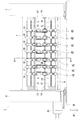
図1は、本実施形態のスリッタ1の全体的構成を示す左側面図である。スリッタ1は、搬送される段ボールを、その搬送方向に沿って裁断する装置で、その構成はよく知られている。本実施形態のスリッタ1では、7組のスリッタヘッド2A〜2Gが、前後方向に並んで配置される。各組のスリッタヘッドは、スリッタ刃受けユニットと、スリッタ刃ユニットとから構成される。たとえば、スリッタヘッド2Eは、上方にスリッタ刃受けユニット3Eを備え、下方にスリッタ刃ユニット4Eを備える。
<Overall configuration>
FIG. 1 is a left side view showing the overall configuration of the
図1において、スリッタ1は、前後に対向する一対のフレーム5、6を有する。上方梁7、および下方梁8が、両フレーム5、6の間にそれぞれ架設される。上方ガイド体9、および下方ガイド体10が、両フレーム5、6の間にそれぞれ架設される。上方ガイド体9は、スリッタ刃受けユニット3Eを含む7つのスリッタ刃受けユニットを前後方向である横方向に案内する。下方ガイド体10は、スリッタ刃ユニット4Eを含む7つのスリッタ刃ユニットを前後方向である横方向に案内する。上方ねじ軸11が、前後方向に延び、上方ガイド体9に固定される。下方ねじ軸12が、前後方向に延び、下方ガイド体10に固定される。上方回転駆動軸13、および下方回転駆動軸14が、両フレーム5、6の間にそれぞれ架設される。回転駆動モータ15が、フレーム6に固定される。両回転駆動軸13、14は、回転駆動モータ15に公知のタイミングベルトおよび歯車機構からなる動力伝達機構を介して連結される。
In FIG. 1, the
(スリッタヘッドの構成)
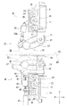
図1および図2を参照して7組のスリッタヘッド2A〜2Gの構成を説明する。図2は、図1に一点鎖線で示すA−A線に従う拡大断面図である。各組のスリッタヘッドのスリッタ刃受けユニットとスリッタ刃ユニットとは、両ガイド体9、10に沿って、独立して前後方向に移動可能に設けられる。各組のスリッタヘッドは同じ構成を有するので、以下、スリッタヘッド2Eを例にして説明する。
(Structure of slitter head)
The configuration of seven sets of slitter heads 2A to 2G will be described with reference to FIGS. FIG. 2 is an enlarged cross-sectional view taken along a line AA indicated by a one-dot chain line in FIG. The slitter blade receiving unit and the slitter blade unit of each pair of slitter heads are provided so as to be independently movable in the front-rear direction along both guide
(スリッタ刃受けユニット3Eの構成)
図2において、スリッタ刃受けユニット3Eは、支持ブロック20を備える。支持ブロック20は、上方ガイド体9に前後方向に移動可能に取り付けられる。延出部21が、支持ブロック20の下端部に固定される。上方回転駆動軸13が、延出部21に形成された貫通孔に挿通される。揺動レバー22が、上方回転駆動軸13を中心に揺動するように延出部21に支持される。回転軸23が、揺動レバー22の先端部に回転可能に支持される。回転軸23は、公知の歯車列を介して上方回転駆動軸13に連結される。
(Configuration of slitter
In FIG. 2, the slitter blade receiving unit 3 </ b> E includes a
横移動サーボモータ24が、支持ブロック20内に固定される。横移動サーボモータ24は、公知の同期型のACサーボモータから構成され、位置検出器を内蔵する。駆動プーリ25が、横移動サーボモータ24の出力軸に固定される。回転体26が、支持ブロック20に回転可能に支持される。回転体26は、上方ねじ軸11と螺合するナット部と、プーリ部とを備える。従動プーリ27が、支持ブロック20に回転可能に支持される。タイミングベルト28が、駆動プーリ25、回転体26のプーリ部、および従動プーリ27に張設される。回転体26は、横移動サーボモータ24の回転に伴って回転する。この回転体26の回転により、支持ブロック20は、そのサーボモータ24の回転方向に従って前方または後方に、サーボモータ24の回転量に相当する横移動量だけ移動する。
A
エアシリンダ29が、支持ブロック20の左側部に揺動自在に支持される。エアシリンダ29の作動棹29Aが、揺動レバー22の先端部に連結される。円形のスリッタ刃受け30が、回転軸23に取り付けられる。エアシリンダ29の作動棹29Aが突出したときに、スリッタ刃受け30の外周が、搬送方向FDに搬送される段ボールの上面に接触するロード位置に、スリッタ刃受け30が位置決めされる。エアシリンダ29の作動棹29Aが引っ込んだときに、スリッタ刃受け30の外周が、搬送方向FDに搬送される段ボールの上面から離間するアンロード位置に、スリッタ刃受け30が位置決めされる。
The
(スリッタ刃ユニット4Eの構成)
図2において、スリッタ刃ユニット4Eは、支持ブロック35を備える。支持ブロック35は、下方ガイド体10に前後方向に移動可能に取り付けられる。延出部36が、支持ブロック35の上端部に固定される。下方回転駆動軸14が、延出部36に形成された貫通孔に挿通される。揺動レバー37が、下方回転駆動軸14を中心に揺動するように延出部36に支持される。回転軸38が、揺動レバー37の中間部分に回転可能に支持される。回転軸38は、公知の歯車列を介して下方回転駆動軸14に連結される。
(Configuration of
In FIG. 2, the
横移動サーボモータ39が、支持ブロック35内に固定される。横移動サーボモータ39は、公知の同期型のACサーボモータから構成され、位置検出器を内蔵する。駆動プーリ40が、横移動サーボモータ39の出力軸に固定される。回転体41が、支持ブロック35に回転可能に支持される。回転体41は、下方ねじ軸12と螺合するナット部と、プーリ部とを備える。従動プーリ42が、支持ブロック35に回転可能に支持される。タイミングベルト43が、駆動プーリ40、回転体41のプーリ部、および従動プーリ42に張設される。回転体41は、横移動サーボモータ39の回転に伴って回転する。この回転体41の回転により、支持ブロック35は、そのサーボモータ39の回転方向に従って前方または後方に、サーボモータ39の回転量に相当する横移動量だけ移動する。
A lateral
一対の支持突部44、45が、支持ブロック35の左側部に形成される。垂直ねじ軸46が、上下方向に延び、両支持突部44、45に回動可能に支持される。昇降サーボモータ47が、支持ブロック35の下端部に固定される。昇降サーボモータ47は、公知の同期型のACサーボモータから構成され、位置検出器を内蔵する。昇降サーボモータ47の出力軸は、垂直ねじ軸46に連結される。上下移動体48は、垂直ねじ軸46と螺合するナット部を有する。連結棹49は、上下移動体48と、揺動レバー37の中間部分とを連結する。
A pair of
スリッタ刃50は、回転軸38に取り付けられる。上下移動体48は、昇降サーボモータ47の回転に伴って上下方向に移動する。この上下移動体48の移動により、揺動レバー37は、そのサーボモータ47の回転方向に従って上方または下方に、サーボモータ47の回転量に相当する角度だけ揺動する。これにより、スリッタ刃50の刃先とスリッタ刃受け30との噛合い量が、調整される。
The
図2において、支持板54が、搬送方向FDに搬送される段ボールを支持するために、延出部36の上端部に固定される。支持板54は、段ボールの下面に接触するように、左右方向に延びて形成される。本実施形態では、支持板54の上面の上下方向の位置が、搬送される段ボールの下面の上下方向の位置であるペーパライン位置HPLである。
In FIG. 2, the
(回転体41の詳細な構成)
回転体41の構成は回転体26の構成と同じであるので、図3を参照して回転体41の構成を例にして説明する。図3は、スリッタユニット4Eの支持ブロック35の内部を拡大して示す右側面図である。図3において、回転体41は、ナット部55と、環状固定部56と、プーリ部57とを備える。ナット部55は、下方ねじ軸12と螺合する。環状固定部56は、支持ブロック35に固定され、ベアリングを介してナット部55を回転可能に支持する。プーリ部57は、ナット部55に固定され、ナット部55と一体に回転する。横移動サーボモータ39の回転は、駆動プーリ40からタイミングベルト43を介してプーリ部57に伝達される。ナット部55は、プーリ部57と共に回転し、螺合する下方ねじ軸12に沿って前後方向に移動する。このナット部55の移動に伴い、環状固定部56が固定された支持ブロック35が前後方向に移動する。すなわち、スリッタ刃50が前後方向である横方向に移動する。
(Detailed configuration of the rotating body 41)
Since the configuration of the
《電気的構成》
図4を参照して本実施形態のスリッタ1の電気的構成を説明する。図4は、スリッタ1の電気的構成を示すブロック図である。図4において、管理装置100は、スリッタ1を含むコルゲートマシンの全体動作を管理する。スリッタ制御装置110は、管理装置100からの指令に従って制御動作を行うと共に、現在の制御状態を管理装置100に通知するために管理装置100に接続される。スリッタ制御装置110は、スリッタ1が段ボールを裁断する加工動作と、スリッタ刃受けユニットおよびスリッタ刃ユニットの横移動を点検する横移動点検動作と、スリッタ刃ユニットの昇降を点検する昇降点検動作とを制御する。
<Electrical configuration>
The electrical configuration of the
プログラムメモリ111は、スリッタ1の加工動作を制御する加工制御プログラムと、スリッタ刃受けユニットのための横移動点検制御プログラムと、スリッタ刃ユニットのための横移動点検制御プログラムと、変化率判断処理プログラムと、昇降点検制御プログラムとを固定記憶する。スリッタ刃ユニットのための横移動点検制御プログラムは、図6に示す横移動点検処理を実行するプログラムである。変化率判断処理プログラムは、図8に示す変化率判断処理を実行するプログラムである。スリッタ刃ユニットのための昇降点検制御プログラムは、図10に示す昇降点検処理を実行するプログラムである。作業メモリ112は、管理装置100から供給された制御指令および各種情報を一時記憶し、また制御プログラムの実行により処理された結果を一時記憶する。設定値メモリ113は、予め定められた各種の設定値を固定記憶する。
The
回転軸38に取り付けられた未使用の刃物51の最上位置に位置する刃先が図2に示すペーパライン位置HPLより所定距離だけ下方の位置に達するまで、上下移動体48を上昇させたときに、その上下移動体48の昇降位置が、スリッタ刃50のアンロード位置に対応する待機昇降位置HUである。待機昇降位置HUは、設定値として、設定値メモリ113に固定記憶される。上下移動体48の昇降位置HSは、待機昇降位置HUを基準にして計測される位置である。
When the vertical moving
また、設定値として、横移動点検処理および昇降点検処理において使用される設定値が、設定値メモリ113に固定記憶される。たとえば、スリッタ刃ユニットの横移動点検処理に使用される設定値として、横移動サーボモータ39などの横移動サーボモータの駆動電流に関する閾値SHP、および平均閾値SHAと、駆動電流の平均値CAの変化率に関する所定変化率DCAと、下方ねじ軸12に沿って定められた前端位置FPA〜FPGおよび後端位置BPA〜BPGとが固定記憶される。スリッタ刃受けユニットの横移動点検処理に使用される設定値も、スリッタ刃ユニットの横移動点検処理に使用される設定値と同様に固定記憶される。スリッタ刃の昇降点検処理に使用される設定値として、昇降サーボモータ47などの昇降サーボモータの駆動電流に関する閾値と、垂直ねじ軸46に沿って上下移動体48が移動できる全移動範囲の上端および下端を規定する上端位置および下端位置とが固定記憶される。
In addition, as setting values, setting values used in the lateral movement inspection process and the lifting inspection process are fixedly stored in the setting
下方ねじ軸12に沿って定められた前端位置FPA〜FPGおよび後端位置BPA〜BPGについて、図5を参照して説明する。図5は、横移動点検処理において、下方ねじ軸12に沿って7つのスリッタ刃ユニット4A〜4Gが前後方向である横方向に移動する動作を説明するための説明図である。図5において、下方ねじ軸12上に定められた全移動範囲TMSは、7つのスリッタ刃ユニット4A〜4Gのいずれかのユニットが下方ねじ軸12上を移動できる範囲である。7つの移動範囲MSA〜MSGは、7つのスリッタ刃ユニット4A〜4Gにそれぞれ対応して下方ねじ軸12上に定められた範囲である。7つの前端位置FPA〜FPG、および7つの後端位置BPA〜BPGは、7つの移動範囲MSA〜MSGの前端および後端をそれぞれ規定する。横移動点検処理において、各スリッタ刃ユニットが、対応する移動範囲を往復移動する。各移動範囲は、隣の移動範囲と重複して定められる。たとえば、移動範囲MSAは、後端領域で、移動範囲MSBと重複し、移動範囲MSCは、前端領域および後端領域で、移動範囲MSB、MSDとそれぞれ重複し、移動範囲MSGは、前端領域で、移動範囲MSFと重複する。
The front end positions FPA to FPG and the rear end positions BPA to BPG determined along the
スリッタ刃の昇降点検処理において、上下移動体が垂直ねじ軸に沿って上端位置および下端位置の間で往復移動するとき、昇降サーボモータは所定の昇降回転速度で回転される。この所定の昇降回転速度は、設定値として、設定値メモリ113に固定記憶される。所定の昇降回転速度は、スリッタ刃が段ボールを裁断するために、スリッタ刃受けと噛合い可能な位置とアンロード位置との間でスリッタ刃を移動させるときの昇降サーボモータの回転速度より低い回転速度である。このため、昇降点検処理において、裁断加工時の負荷より大きな負荷を昇降サーボモータに加えることはない。また、スリッタ刃受けユニットおよびスリッタ刃ユニットの横移動点検処理において、各ユニットの回転体がねじ軸に沿って前端位置および後端位置の間で往復移動するとき、横移動サーボモータは所定の横移動回転速度で回転される。この所定の横移動回転速度は、設定値として、設定値メモリ113に固定記憶される。所定の横移動回転速度は、スリッタ刃受けおよびスリッタ刃が段ボールを裁断するために、各ユニットを所定の加工位置まで横移動させるときの横移動サーボモータの回転速度より低い回転速度である。このため、横移動点検処理において、加工位置まで横移動する際に加わる負荷より大きな負荷を横移動サーボモータに加えることはない。
In the lifting / lowering inspection process of the slitter blade, when the vertical moving body reciprocates between the upper end position and the lower end position along the vertical screw shaft, the lifting servo motor is rotated at a predetermined lifting rotation speed. This predetermined ascending / descending rotational speed is fixedly stored in the
操作パネル114が、スリッタ制御装置110に各種の指令を入力するために設けられる。操作パネル114は、点検処理を開始させるための点検開始キー115を有する。
An
スリッタ刃受けのための横移動位置検出器群117A〜117Gが、スリッタ制御装置110に接続され、7組のスリッタヘッド2A〜2Gにおける7つのスリッタ刃受けユニットの前後方向の位置である横移動位置をそれぞれ検出するために設けられる。位置検出器群117A〜117Gは、横移動サーボモータ24を含む7つの横移動サーボモータにそれぞれ内蔵された7つの位置検出器から構成される。スリッタ刃のための横移動位置検出器群118A〜118Gが、スリッタ制御装置110に接続され、7組のスリッタヘッド2A〜2Gにおける7つのスリッタ刃ユニットの前後方向の位置である横移動位置を検出するために設けられる。位置検出器群118A〜118Gは、横移動サーボモータ39を含む7つの横移動サーボモータにそれぞれ内蔵された7つの位置検出器から構成される。たとえば、スリッタ刃ユニット4Eにおいて、位置検出器118Eが、図3に示すように横移動サーボモータ39に設けられる。昇降位置検出器群119A〜119Gが、スリッタ制御装置110に接続され、7つのスリッタ刃ユニットにおける7つの上下移動体の上下方向の位置である昇降位置をそれぞれ検出するために設けられる。位置検出器群119A〜119Gは、昇降サーボモータ47を含む7つの昇降サーボモータにそれぞれ内蔵された7つの位置検出器から構成される。
The lateral movement
平均値メモリ116は、横移動点検処理、および昇降点検処理が実行されたときに、各サーボモータの駆動電流の平均値を固定記憶する。平均値メモリ116は、電子的に書き換え可能な不揮発性メモリから構成される。横移動点検処理、および昇降点検処理が、定期的に実行されることから、平均値メモリ116は、各点検処理の実行時に算出された平均値を時系列に記憶する。本実施形態では、各点検処理は、毎月実行される。
The
位置切換回路120が、スリッタ制御装置110に接続され、スリッタ制御装置110からの指令に従って、7つのスリッタ刃受けユニットにおける7つのエアシリンダの作動をそれぞれ制御する。図4において、エアシリンダ29を含む7つのエアシリンダは、エアシリンダ群121として示され、スリッタ刃受け30を含む7つのスリッタ刃受けは、スリッタ刃受け群122として示される。スリッタ刃受けのための横移動駆動回路123は、スリッタ制御装置110に接続され、スリッタ制御装置110からの指令に従って、7つの横移動サーボモータの回転方向、回転量、および回転速度を制御する。図4において、横移動サーボモータ24を含む7つの横移動サーボモータは、横移動サーボモータ群124として示される。
A
昇降駆動回路125は、スリッタ制御装置110に接続され、スリッタ制御装置110からの指令に従って、7つの昇降サーボモータの回転方向、回転量、および回転速度を制御する。図4において、昇降サーボモータ47を含む7つの昇降サーボモータは、昇降サーボモータ群126として示され、スリッタ刃50を含む7つのスリッタ刃は、スリッタ刃群127として示される。スリッタ刃のための横移動駆動回路128は、スリッタ制御装置110に接続され、スリッタ制御装置110からの指令に従って、7つの横移動サーボモータの回転方向、回転量、および回転速度を制御する。図4において、横移動サーボモータ39を含む7つの横移動サーボモータは、横移動サーボモータ群129として示される。
The
表示部130が、スリッタ制御装置110に接続され、スリッタ制御装置110からの指令に従って、操作パネル114から入力された情報、およびエラーメッセージなどの各種の情報を表示するために設けられる。
A
電流検出回路群131A〜131Gが、スリッタ制御装置110に接続され、7つのスリッタ刃受けユニットにおける7つの横移動サーボモータの駆動電流をそれぞれ検出するために設けられる。電流検出回路群131A〜131Gの各電流検出回路は、スリッタ刃受けのための横移動駆動回路123が横移動サーボモータ群124の各横移動サーボモータに供給する駆動電流を検出する回路である。電流検出回路群132A〜132Gが、スリッタ制御装置110に接続され、7つのスリッタ刃ユニットにおける7つの昇降サーボモータの駆動電流をそれぞれ検出するために設けられる。電流検出回路群132A〜132Gの各電流検出回路は、スリッタ刃のための昇降駆動回路126が昇降サーボモータ群126の各昇降サーボモータに供給する駆動電流を検出する回路である。電流検出回路群133A〜133Gが、スリッタ制御装置110に接続され、7つのスリッタ刃ユニットにおける7つの横移動サーボモータの駆動電流をそれぞれ検出するために設けられる。電流検出回路群133A〜133Gの各電流検出回路は、スリッタ刃のための横移動駆動回路128が横移動サーボモータ群129の各横移動サーボモータに供給する駆動電流を検出する回路である。
Current detection circuit groups 131 </ b> A to 131 </ b> G are connected to the
たとえば、横移動サーボモータ24の電流検出回路131Eは、横移動サーボモータ24に駆動電流を供給するために横移動駆動回路123が備えるサーボアンプの出力側に接続された分圧抵抗などを含んで構成される。この分圧抵抗により分圧された電圧を検出することにより、横移動サーボモータ24の駆動電流が検出される。電流検出回路群132A〜132G、および電流検出回路群133A〜133Gの各電流検出回路は、電流検出回路131Eと同様な構成である。
For example, the current detection circuit 131E of the
《実施形態の動作および作用》
本実施形態のスリッタ1の動作および作用について、以下に説明する。なお、スリッタ1が段ボールを裁断する動作は、特許第3717167号公報および特開2011−88393号公報などにより公知であるので、スリッタ1がねじ軸に沿って移動する各部材を点検する動作および作用についてのみ、説明する。特に、スリッタ刃受けユニットの横移動点検処理と、スリッタ刃ユニットの横移動点検処理とは、略同じ処理であるので、スリッタ刃ユニットの横移動点検処理を例にして、図6を参照して説明する。
<< Operation and Action of Embodiment >>
The operation and action of the
(スリッタ刃ユニットの横移動点検処理)
7つのスリッタ刃ユニット4A〜4Gの横移動点検処理を実行するために、作業員が、スリッタ刃ユニットの横移動点検を選択するために操作パネル114を操作する。その後に、作業員は、点検開始キー115を操作する。スリッタ制御装置110は、この点検開始キー115の操作を検出し、点検モードを作業メモリ112に記憶して設定する。この点検モードの設定により、スリッタ制御装置110は、プログラムメモリ111に記憶されたスリッタ刃ユニットのための横移動点検制御プログラムの実行を開始する。スリッタ制御装置110は、横移動点検制御プログラムの実行が終了したときに、点検モードの設定を解除する。点検モードが設定されている間、スリッタ制御装置110は、スリッタ刃受けユニットおよびスリッタ刃ユニットを手動で移動させる動作を禁止する。この横移動点検制御プログラムの実行により、図6に示す各処理が実行される。図6に示す各処理は、スリッタ制御装置110が実行する処理である。
(Slitter blade unit lateral movement inspection process)
In order to execute the lateral movement inspection process of the seven
S1において、7つのスリッタ刃ユニット4A〜4Gがアンロード位置に位置決めされる。具体的には、昇降位置検出器群119A〜119Gの検出結果を基に、上下移動体48を含む7つの上下移動体が、昇降サーボモータ47を含む昇降サーボモータ群126により、所定の待機昇降位置HUに位置決めされる。これにより、スリッタ刃50を含む7つのスリッタ刃がアンロード位置に位置決めされる。
In S1, the seven
S2において、7つのスリッタ刃ユニット4A〜4Gが、7つの前端位置FPA〜FPGにそれぞれ位置決めされる。具体的には、スリッタ刃のための横移動位置検出器群118A〜118Gの検出結果を基に、回転体41を含む7つの回転体が、横移動サーボモータ39を含む横移動サーボモータ群129により、図5に示す前端位置FPA〜FPGにそれぞれ位置決めされる。
In S2, the seven
S3において、初期設定が実行される。具体的には、作業メモリ112の所定記憶領域にそれぞれ記憶された電流ピーク値CP、累積電流値CR、および検出回数カウント値AVCなどの各種の記憶情報が、クリアされる。電流ピーク値CP、および累積電流値CRは、横移動サーボモータ群129の各モータに対応して記憶される。
In S3, initial setting is executed. Specifically, various stored information such as the current peak value CP, the accumulated current value CR, and the detection count value AVC stored in the predetermined storage area of the working
S4において、スリッタ刃ユニット4A〜4Gが、横移動サーボモータ群129により、図5に示す前端位置FPA〜FPGから、後方側に向かって移動を開始する。このとき、横移動サーボモータ群129は、設定値メモリ113に記憶された所定の横移動回転速度で回転される。
In S4, the
S5において、スリッタ刃ユニット4A〜4Gが後方側に向かって移動している間に、横移動サーボモータ群129にそれぞれ供給される駆動電流の電流値CXが、スリッタ刃のための電流検出回路群132A〜132Gにより、それぞれ検出される。
In S5, while the
S6において、横移動サーボモータ群129の各モータについて、検出された駆動電流の電流値CXが、電流ピーク値CP以上であるか否かが判断される。S3において、電流ピーク値CPは、クリアされているので、S6では、電流値CXは電流ピーク値CP以上であると判断され(S6:YES)、S7の処理が実行される。
In S6, for each motor of the lateral movement
S7において、各横移動サーボモータについて、検出された駆動電流の電流値CXが、電流ピーク値CPとして、作業メモリ112に記憶される。
In S7, the detected drive current value CX for each lateral movement servomotor is stored in the
S8において、各横移動サーボモータについて、検出された駆動電流の電流値CXが、前端位置に対応して記憶される。たとえば、スリッタ刃ユニット4Eの横移動サーボモータ39について、電流値CXが、前端位置FPAに対応して作業メモリ112に記憶される。また、電流値CXが、累積電流値CRに加算されて作業メモリ112に記憶される。
In S8, the detected drive current value CX for each lateral movement servomotor is stored in correspondence with the front end position. For example, for the lateral
S9において、検出回数カウント値AVCが「1」だけインクリメントされる。S3において、検出回数カウント値AVCは、クリアされているので、S9では、検出回数カウント値は、「0」から「1」にインクリメントされる。 In S9, the detection count value AVC is incremented by “1”. In S3, since the detection count value AVC is cleared, in S9, the detection count value is incremented from “0” to “1”.
S10において、横移動位置検出器群118A〜118Gの検出結果を基に、7つのスリッタ刃ユニット4A〜4Gが、図5に示す後端位置BPA〜BPGに位置決めされたか否かが判断される。全てのスリッタ刃ユニット4A〜4Gが位置決めされたと判断されないとき(S10:NO)、S5の処理が再度実行される。全てのスリッタ刃ユニット4A〜4Gが位置決めされたと判断されたとき(S10:YES)、S11の処理が実行される。
In S10, based on the detection results of the lateral movement
S5の処理が再度実行される場合、各スリッタ刃ユニットが所定距離だけ移動した後に、各横移動サーボモータについて、電流値CXが検出される。本実施形態では、各スリッタ刃ユニットが所定距離として10mmだけ移動すると、電流値CXが検出される。S6において、電流値CXが電流ピーク値CP以上であるか否かが判断され、電流値CXが電流ピーク値CP以上であると判断されないとき(S6:NO)、S8の処理が実行される。電流値CXが電流ピーク値CP以上であると判断されたとき(S6:YES)、前述したS7の処理が実行される。 When the process of S5 is performed again, the current value CX is detected for each lateral movement servomotor after each slitter blade unit has moved a predetermined distance. In the present embodiment, when each slitter blade unit moves by 10 mm as a predetermined distance, the current value CX is detected. In S6, it is determined whether or not the current value CX is equal to or greater than the current peak value CP, and when it is not determined that the current value CX is equal to or greater than the current peak value CP (S6: NO), the process of S8 is executed. When it is determined that the current value CX is equal to or greater than the current peak value CP (S6: YES), the process of S7 described above is executed.
S8において、電流値CXが、前端位置より10mmだけ後方に移動した位置に対応して作業メモリ112に記憶される。また、電流値CXが、累積電流値CRに加算されて作業メモリ112に記憶される。S9において、検出回数カウント値AVCが「1」から「2」へインクリメントされる。S10において、全てのスリッタ刃ユニット4A〜4Gが位置決めされたか否かが判断される。全てのスリッタ刃ユニット4A〜4Gが位置決めされたと判断されるまで、S5〜S10の処理が繰り返され、S8では、電流値CXが、10mmごと後方に変化する位置に対応して作業メモリ112に記憶される。
In S8, the current value CX is stored in the
全てのスリッタ刃ユニット4A〜4Gが位置決めされたと判断されると(S10:YES)、S11の処理が実行され、全てのスリッタ刃ユニット4A〜4Gが、横移動サーボモータ群129により、図5に示す後端位置BPA〜BPGから、前方側に向かって移動を開始する。このとき、横移動サーボモータ群129は、設定値メモリ113に記憶された所定の横移動回転速度で回転される。
If it is determined that all the
S12において、スリッタ刃ユニット4A〜4Gが前方側に向かって移動している間に、横移動サーボモータ群129の駆動電流の電流値CXが、電流検出回路群132A〜132Gにより、それぞれ検出される。
In S12, while the
S13において、横移動サーボモータ群129の各モータについて、検出された駆動電流の電流値CXが、電流ピーク値CP以上であるか否かが判断される。電流値CXは電流ピーク値CP以上であると判断されないと(S6:NO)、S15の処理が実行される。電流値CXは電流ピーク値CP以上であると判断されると(S6:YES)、S14の処理が実行される。
In S13, for each motor in the lateral movement
S14において、各横移動サーボモータについて、検出された駆動電流の電流値CXが、電流ピーク値CPとして、作業メモリ112に記憶される。
In S14, the detected drive current value CX of each lateral movement servomotor is stored in the
S15において、各横移動サーボモータについて、検出された駆動電流の電流値CXが、後端位置に対応して記憶される。たとえば、スリッタ刃ユニット4Eの横移動サーボモータ39について、電流値CXが、後端位置BPAに対応して作業メモリ112に記憶される。また、電流値CXが、累積電流値CRに加算されて作業メモリ112に記憶される。
In S15, the detected drive current value CX for each lateral movement servomotor is stored in correspondence with the rear end position. For example, for the lateral
S16において、検出回数カウント値AVCが「1」だけインクリメントされる。具体的には、S16では、横移動点検処理において、電流値CXを検出した回数がカウントされ、作業メモリ112に記憶される。
In S16, the detection count value AVC is incremented by “1”. Specifically, in S <b> 16, the number of times the current value CX is detected in the lateral movement inspection process is counted and stored in the
S17において、横移動位置検出器群118A〜118Gの検出結果を基に、7つのスリッタ刃ユニット4A〜4Gが、図5に示す前端位置FPA〜FPGに位置決めされたか否かが判断される。全てのスリッタ刃ユニット4A〜4Gが位置決めされたと判断されないとき(S17:NO)、S12の処理が再度実行される。全てのスリッタ刃ユニット4A〜4Gが位置決めされたと判断されたとき(S17:YES)、S18の処理が実行される。
In S17, based on the detection results of the lateral movement
S18において、電流ピーク値CPが、閾値SHP以上であるか否かが判断される。電流ピーク値CPが、閾値SHP以上であると判断されないと(S18:NO)、S20の処理が実行される。電流ピーク値CPが、閾値SHP以上であると判断されると(S18:YES)、S19の処理が実行され、エラーメッセージが表示部130に表示される。エラーメッセージとして、電流ピーク値CPが閾値SHP以上である横移動サーボモータを備えるスリッタ刃ユニットを特定するユニット情報と、そのスリッタ刃ユニットの移動範囲を特定する範囲情報とが表示され、そのスリッタ刃ユニットの移動範囲に不具合が発生していることを示すメッセージを表示する。作業員は、エラーメッセージを見て、どのスリッタ刃ユニットの移動範囲に不具合が発生したのかを把握することができる。すなわち、作業員は、エラーメッセージの内容から、移動範囲MSA〜MSGのうち、下方ねじ軸12上のどの移動範囲に不具合が発生したのかを把握することができる。通常、電流ピーク値CPが閾値SHP以上である場合、その電流ピーク値CPが発生した位置において下方ねじ軸12に紙粉が固着している恐れがあり、この紙粉の固着により、下方ねじ軸12の特定箇所を通過するときに横移動サーボモータに大きな負荷が加わったと考えられる。
In S18, it is determined whether or not the current peak value CP is equal to or greater than a threshold value SHP. If it is not determined that the current peak value CP is equal to or greater than the threshold value SHP (S18: NO), the process of S20 is executed. If it is determined that the current peak value CP is equal to or greater than the threshold value SHP (S18: YES), the process of S19 is executed and an error message is displayed on the
また、本実施形態では、S8およびS15において、各横移動サーボモータについて、各スリッタ刃ユニットが10mmの距離だけ移動するごとに、電流値CXが、各スリッタ刃ユニットの移動位置に対応して作業メモリ112に記憶される。この電流値CXと移動位置との対応付けにより、電流値CXが急激に増大したスリッタ刃ユニットの移動位置が、エラーメッセージとして表示部130に表示される。たとえば、図7に示すように、電流値CXとスリッタ刃ユニットの移動位置との関係が、表示部130に表示される。具体的には、図5に示す全移動範囲TMS内の前方側から300〜800mmの範囲において、10mm単位の移動位置に対応して、電流値CXが表示される。図7では、500mmの移動位置近傍と、700mmの移動位置近傍とにおいて、電流値CXが急激に増大して閾値SHP以上になっていることから、作業員は、これらの移動位置近傍において下方ねじ軸12に紙粉が固着しているおそれがあることを容易に把握することができる。
In this embodiment, in S8 and S15, for each lateral movement servo motor, each time the slitter blade unit moves by a distance of 10 mm, the current value CX corresponds to the movement position of each slitter blade unit. Stored in the
S20において、累積電流値CRを検出回数カウント値AVCで割ることにより、電流値CXの平均値CAが算出され、作業メモリ112に記憶される。
In S <b> 20, the average value CA of the current value CX is calculated by dividing the accumulated current value CR by the detection count value AVC and stored in the
S21において、平均値CAが、平均閾値SHA以上であるか否かが判断される。平均値CAが、平均閾値SHA以上であると判断されないと(S21:NO)、横移動点検処理が終了する。平均値CAが、平均閾値SHA以上であると判断されると(S21:YES)、S22の処理が実行され、エラーメッセージが表示部130に表示される。エラーメッセージとして、平均値CAが平均閾値SHA以上である横移動サーボモータを備えるスリッタ刃ユニットを特定するユニット情報が表示される。作業員は、エラーメッセージを見て、どのスリッタ刃ユニットに不具合が発生したのかを把握することができる。すなわち、作業員は、どのスリッタ刃ユニットの横移動サーボモータまたは回転体に不具合が発生したのかを把握することができる。
In S21, it is determined whether or not the average value CA is equal to or greater than the average threshold SHA. If it is not determined that the average value CA is equal to or greater than the average threshold SHA (S21: NO), the lateral movement inspection process ends. If it is determined that the average value CA is equal to or greater than the average threshold SHA (S21: YES), the process of S22 is executed and an error message is displayed on the
スリッタ刃受けユニットの横移動点検処理も、スリッタ刃ユニットの横移動点検処理と同様に実行される。この結果、作業員は、表示部130に表示されるエラーメッセージの内容から、7つの移動範囲のうち、上方ねじ軸11上のどの移動範囲に不具合が発生したのかを把握することができる。具体的には、電流値が急激に増大して閾値SHP以上になった場合に、図7に示すような表示部130の表示により、作業員は、その電流値の急激な増大が発生したスリッタ刃受けユニットの移動位置近傍において、上方ねじ軸11に紙粉が固着しているおそれがあることを容易に把握することができる。また、エラーメッセージとして、平均値が平均閾値以上である横移動サーボモータを備えるスリッタ刃受けユニットを特定するユニット情報が表示部130に表示されることにより、作業員は、エラーメッセージを見て、どのスリッタ刃受けユニットの横移動サーボモータまたは回転体に不具合が発生したのかを把握することができる。
The lateral movement inspection process of the slitter blade receiving unit is also executed in the same manner as the lateral movement inspection process of the slitter blade unit. As a result, the worker can grasp in which movement range on the upper screw shaft 11 a defect has occurred among the seven movement ranges from the content of the error message displayed on the
(変化率判断処理)
スリッタ刃ユニットの横移動点検処理のS20において算出された平均値CAの変化率を判断する変化率判断処理について、図8を参照して説明する。変化率判断処理は、スリッタ刃ユニットの不具合が現実に発生して平均値CAが平均閾値SHAに達する前に、スリッタ刃ユニットの不具合の可能性を事前に点検するための処理である。作業員が点検開始キー115を操作することにより、スリッタ制御装置110は、点検モードを作業メモリ112に記憶して設定する。この点検モードの設定により、スリッタ制御装置110は、プログラムメモリ111に記憶された変化率判断処理プログラムの実行を開始する。この変化率判断処理プログラムの実行により、図8に示す各処理が実行される。図8に示す各処理は、スリッタ制御装置110が実行する処理である。
(Change rate judgment process)
The change rate determination process for determining the change rate of the average value CA calculated in S20 of the slitter blade unit lateral movement inspection process will be described with reference to FIG. The change rate determination process is a process for checking in advance the possibility of a failure of the slitter blade unit before the average value CA reaches the average threshold SHA when the failure of the slitter blade unit actually occurs. When the operator operates the inspection start key 115, the
S30において、図6に示す横移動点検処理が終了したか否かが判断される。終了したと判断されないとき(S30:NO)、S30の判断処理が繰り返される。終了したと判断されたとき(S30:YES)、S31の処理が実行される。 In S30, it is determined whether or not the lateral movement inspection process shown in FIG. When it is not determined that the process has been completed (S30: NO), the determination process of S30 is repeated. When it is determined that the process has been completed (S30: YES), the process of S31 is executed.
S31において、横移動点検処理の実行時期と、S20において算出された平均値CAとが関連付けられて平均値メモリ116に記憶される。具体的には、横移動点検処理が終了した時点での年月日を表す点検時期情報がスリッタ制御装置110のタイマ時計から取得される。また、S20において作業メモリ112に一時記憶された平均値CAが読み出される。取得された点検時期情報と、読み出された平均値CAとが、互いに関連付けされて平均値メモリ116に記憶される。
In S31, the execution time of the lateral movement inspection process and the average value CA calculated in S20 are associated with each other and stored in the
S32において、S20において算出された平均値CAが平均閾値SHA以上であるのか否かが判断される。平均値CAが平均閾値SHA以上であると判断されると(S32:YES)、変化率判断処理が終了する。平均値CAが平均閾値SHA以上である場合、スリッタ1に現実に不具合が発生していることから、不具合の発生前の事前点検である変化率判断処理の実行は、不要となる。
In S32, it is determined whether or not the average value CA calculated in S20 is equal to or greater than the average threshold SHA. When it is determined that the average value CA is equal to or greater than the average threshold SHA (S32: YES), the change rate determination process ends. When the average value CA is equal to or greater than the average threshold SHA, the
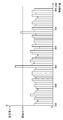
S33において、平均値CAの変化率が算出される。本実施形態では、横移動点検処理は毎月実行されることから、平均値メモリ116は、毎月の平均値CAを記憶する。変化率は、今月の平均値CAから先月の平均値CAを差し引いた差分である。通常、各横移動サーボモータにより駆動される回転体のナット部とねじ軸との間の摩擦抵抗は、ねじ軸上への紙粉の堆積、潤滑油の減少、または接触部分の摩耗などが進行することに伴い、徐々に増加する。この摩擦抵抗の増加に伴い、各横移動サーボモータの駆動電流は、徐々に大きくなり、平均値CAも、徐々に大きくなる。
In S33, the change rate of the average value CA is calculated. In this embodiment, since the lateral movement inspection process is executed every month, the
S34において、S33で算出された変化率が、所定変化率DCA以上であるのか否かが判断される。所定変化率DCA以上であると判断されないとき(S34:NO)、変化率判断処理が終了する。所定変化率DCA以上であると判断されるとき(S34:YES)、S35の処理が実行される。 In S34, it is determined whether or not the change rate calculated in S33 is equal to or greater than a predetermined change rate DCA. When it is not determined that the change rate is equal to or greater than the predetermined change rate DCA (S34: NO), the change rate determination process ends. When it is determined that the change rate is equal to or higher than the predetermined change rate DCA (S34: YES), the process of S35 is executed.
通常、回転体のナット部、ねじ軸、またはサーボモータの軸受けなどの接触部分において、紙粉の堆積、潤滑不足、または摩耗などが進むと、サーボモータに大きな負荷が継続的に加わる現象が発生し始める。この現象の初期段階では、サーボモータの駆動電流の平均値CAは平均閾値SHAに達することはないが、駆動電流の平均値CAが大幅に増加し続ける傾向にある。図9は、毎月実行される横移動点検処理において算出された平均値CAの変化と、経過月数との関係を示す。図9において、平均値CAは、経過した月数が大きくなるのに伴い、徐々に増加する。しかし、72カ月が経過した時点から、平均値CAの変化率が大きくなり、88カ月から3カ月連続して、平均値CAの変化率は所定変化率DCA以上になる。その後、平均値CAは、急激に増大し、94カ月が経過した時点で平均閾値SHAを超えることになる。94か月が経過した時点で実行された横移動点検処理において、S22でエラーメッセージが表示部130に表示されることから、作業員は不具合の保守作業を行う。そのため、95カ月以降は、平均値CAは正常な値に戻る。
Normally, when the accumulation of paper dust, lack of lubrication, or wear progresses at the contact portion such as the nut of the rotating body, screw shaft, or servo motor bearing, a phenomenon occurs in which a large load is continuously applied to the servo motor. Begin to. In the initial stage of this phenomenon, the average value CA of the drive current of the servo motor does not reach the average threshold SHA, but the average value CA of the drive current tends to continue to increase significantly. FIG. 9 shows the relationship between the change in average value CA calculated in the lateral movement inspection process executed every month and the number of elapsed months. In FIG. 9, the average value CA gradually increases as the number of elapsed months increases. However, the rate of change of the average value CA increases from the time when 72 months elapse, and the rate of change of the average value CA becomes equal to or greater than the predetermined rate of change DCA for 3 consecutive months from 88 months. Thereafter, the average value CA increases rapidly and exceeds the average threshold SHA when 94 months have passed. In the lateral movement inspection process executed when 94 months have passed, an error message is displayed on the
S35において、変化率が所定変化率DCA以上である状態が所定数の月連続しているのか否かが判断される。本実施形態では、所定数の月は、3カ月である。連続していると判断されないとき(S35:NO)、変化率判断処理が終了する。連続していると判断されるとき(S35:YES)、S36の処理が実行される。たとえば、図9において、88カ月から91カ月までの3カ月間で実行された横移動点検処理において算出された平均値CAの変化率は、3カ月連続して所定変化率DCA以上であることから、S35において、変化率が所定変化率DCA以上である状態が所定数の月連続していると判断される。 In S35, it is determined whether or not a state where the change rate is equal to or greater than the predetermined change rate DCA continues for a predetermined number of months. In the present embodiment, the predetermined number of months is three months. When it is not determined that it is continuous (S35: NO), the change rate determination process ends. When it is determined that they are continuous (S35: YES), the process of S36 is executed. For example, in FIG. 9, the change rate of the average value CA calculated in the lateral movement inspection process executed in the three months from 88 months to 91 months is equal to or greater than the predetermined change rate DCA for three consecutive months. In S35, it is determined that the state where the change rate is equal to or greater than the predetermined change rate DCA continues for a predetermined number of months.
S36において、警告メッセージが表示部130に表示される。S36の処理後、変化率判断処理が終了する。警告メッセージとして、平均値CAの変化率が所定数の月連続して所定変化率DCA以上である横移動サーボモータを備えるスリッタ刃ユニットを特定するユニット情報が表示され、そのスリッタ刃ユニットに不具合が発生するおそれがあることを示すメッセージを表示する。作業員は、警告メッセージを見て、どのスリッタ刃ユニットに不具合が発生するおそれがあるのかを事前に把握することができる。すなわち、作業員は、どのスリッタ刃ユニットの横移動サーボモータまたは回転体に不具合が発生するおそれがあるのかを事前に把握して、その不具合が現実に発生する前に保守作業を行うことができる。
In S36, a warning message is displayed on the
図8に示す変化率判断処理は、スリッタ刃ユニットの横移動点検処理において算出された平均値CAの変化率について判断する処理であるが、スリッタ刃受けユニットの横移動点検処理において算出された平均値CAの変化率についても、同様に実行される。また、図8に示す変化率判断処理は、後述のスリッタ刃ユニットの昇降点検処理において算出された平均値CAの変化率についても、同様に実行される。 The change rate determination process shown in FIG. 8 is a process for determining the change rate of the average value CA calculated in the lateral movement inspection process of the slitter blade unit, but the average calculated in the lateral movement inspection process of the slitter blade receiving unit. The change rate of the value CA is similarly executed. Further, the change rate determination process shown in FIG. 8 is similarly executed for the change rate of the average value CA calculated in the slitter blade unit lifting / lowering inspection process described later.
(スリッタ刃ユニットの昇降点検処理)
スリッタ刃ユニットの昇降点検処理について、図8を参照して説明する。昇降点検処理が、図6に示すスリッタ刃ユニットの横移動点検処理と同じ処理については、同じ記号を付して、その説明を省略する。
(Slitter blade unit lifting inspection process)
The raising / lowering inspection process of a slitter blade unit is demonstrated with reference to FIG. The same reference numerals are given to the same processing as the vertical movement inspection processing of the slitter blade unit shown in FIG. 6, and the description thereof is omitted.
7つのスリッタ刃ユニット4A〜4Gの昇降点検処理を実行するために、作業員が、スリッタ刃ユニットの昇降点検を選択するために操作パネル114を操作する。その後に、作業員は、点検開始キー115を操作する。スリッタ制御装置110は、この点検開始キー115の操作を検出し、点検モードを作業メモリ112に記憶して設定する。この点検モードの設定により、スリッタ制御装置110は、プログラムメモリ111に記憶されたスリッタ刃ユニットのための昇降点検制御プログラムの実行を開始する。スリッタ制御装置110は、昇降点検制御プログラムの実行が終了したときに、点検モードの設定を解除する。点検モードが設定されている間、スリッタ制御装置110は、スリッタ刃受けユニットおよびスリッタ刃ユニットを手動で移動させる動作を禁止する。この昇降点検制御プログラムの実行により、図8に示す各処理が実行される。図8に示す各処理は、スリッタ制御装置110が実行する処理である。
In order to execute the elevation inspection process of the seven
SA1において、7つのスリッタ刃受けユニット3A〜3Gが、エアシリンダ29を含むエアシリンダ群121の作動により、アンロード位置に位置決めされる。全てのスリッタ刃受けユニットがアンロード位置に位置決めされることにより、スリッタ刃が上昇したときに、スリッタ刃がスリッタ刃受けと干渉することを防止する。
In SA <b> 1, the seven slitter blade receiving units 3 </ b> A to 3 </ b> G are positioned at the unload position by the operation of the
SA2において、スリッタ刃ユニット4A〜4Gの7つの上下移動体が、昇降位置検出器群119A〜119Gの検出結果を基に、昇降サーボモータ47を含む昇降サーボモータ群126により、垂直ねじ軸46を含む7つの垂直ねじ軸において定められた所定の下端位置にそれぞれ位置決めされる。その後、S3の初期設定が、前述のように実行される。
In SA2, the seven vertical moving bodies of the
SA4において、スリッタ刃ユニット4A〜4Gが、昇降サーボモータ群126により、下端位置から、上方側に向かって移動を開始する。このとき、昇降サーボモータ群126は、設定値メモリ113に記憶された所定の昇降回転速度で回転される。この上方側に向かって移動している間に、S5〜S9の処理が前述のように実行され、電流値CXが記憶され、電流値CXが累積電流値CRに加算される。
In SA4, the
SA10において、昇降位置検出器群119A〜119Gの検出結果を基に、7つのスリッタ刃ユニット4A〜4Gが、垂直ねじ軸46を含む7つの垂直ねじ軸において定められた所定の上端位置にそれぞれ位置決めされたか否かが判断される。全てのスリッタ刃ユニット4A〜4Gが位置決めされたと判断されないとき(SA10:NO)、S5の処理が再度実行される。全てのスリッタ刃ユニット4A〜4Gが位置決めされたと判断されたとき(SA10:YES)、SA11の処理が実行される。
In SA10, based on the detection results of the lift
SA11において、全てのスリッタ刃ユニット4A〜4Gが、昇降サーボモータ群126により、上端位置から、下方側に向かって移動を開始する。このとき、昇降サーボモータ群126は、設定値メモリ113に記憶された所定の昇降回転速度で回転される。S12〜S16の処理が前述のように実行され、電流値CXが記憶され、電流値CXが累積電流値CRに加算される。
In SA11, all the
SA17において、昇降位置検出器群119A〜119Gの検出結果を基に、7つのスリッタ刃ユニット4A〜4Gが、下端位置に位置決めされたか否かが判断される。全てのスリッタ刃ユニット4A〜4Gが位置決めされたと判断されないとき(SA17:NO)、S12の処理が再度実行される。全てのスリッタ刃ユニット4A〜4Gが位置決めされたと判断されたとき(SA17:YES)、S18の処理が実行される。
In SA17, based on the detection results of the lift
電流ピーク値CPが閾値SHP以上であると判断されると(S18:YES)、SA19において、エラーメッセージが表示部130に表示される。エラーメッセージとして、電流ピーク値CPが閾値SHP以上である昇降サーボモータを備えるスリッタ刃ユニットを特定するユニット情報と、そのスリッタ刃ユニットの垂直ねじ軸において不具合のある位置を特定する位置情報とが表示される。
If it is determined that current peak value CP is equal to or greater than threshold value SHP (S18: YES), an error message is displayed on
本実施形態では、S8およびS15において、各昇降サーボモータについて、各上下移動体が10mmの距離だけ移動するごとに、電流値CXが、各上下移動体の昇降位置に対応して作業メモリ112に記憶される。この電流値CXと昇降位置との対応付けにより、電流値CXが急激に増大した上下移動体の昇降位置が、エラーメッセージとして表示部130に表示される。この表示部130のエラーメッセージにより、作業員は、電流値CXが急激に増大している昇降位置近傍において、垂直ねじ軸に紙粉が固着しているおそれがあることを容易に把握することができる。
In the present embodiment, in S8 and S15, for each lifting servomotor, each time each vertical moving body moves by a distance of 10 mm, the current value CX is stored in the
平均値CAが平均閾値SHA以上であると判断されると(S21:YES)、SA22において、エラーメッセージが表示部130に表示される。エラーメッセージとして、平均値CAが平均閾値SHA以上である昇降サーボモータを備えるスリッタ刃ユニットを特定するユニット情報が表示される。作業員は、エラーメッセージを見て、どのスリッタ刃ユニットに不具合が発生したのかを把握することができる。すなわち、作業員は、どのスリッタ刃ユニットの昇降サーボモータまたは上下移動体に不具合が発生したのかを把握することができる。
If it is determined that the average value CA is equal to or greater than the average threshold SHA (S21: YES), an error message is displayed on the
《実施形態の効果》
本実施形態では、電流検出回路群131A〜131G、133A〜133G、および電流検出回路群132A〜132Gは、横移動駆動回路123、128、および昇降駆動回路125に電気的に接続して設けられることから、スリッタ刃受け30およびスリッタ50との位置関係を考慮して設置する作業が不要となり、回転体および上下移動体の不具合、または、ねじ軸の不具合を簡易な構成にて点検することができる。
<< Effects of the Embodiment >>
In the present embodiment, the current detection circuit groups 131 </ b> A to 131 </ b> G, 133 </ b> A to 133 </ b> G, and the current detection circuit groups 132 </ b> A to 132 </ b> G are provided to be electrically connected to the lateral
本実施形態では、横移動点検処理において、表示部130が、不具合のあるスリッタ刃受けユニットまたはスリッタ刃ユニットを特定するユニット情報、およびその不具合のあるユニットの移動範囲を特定する範囲情報をエラーメッセージとして表示することから、作業員は、多数あるユニットのうちから不具合のあるユニットを容易に把握することができるとともに、ねじ軸11、12上において不具合のある移動範囲を確実に把握することができる。また、表示部130が、電流値CXが急激に増大した各ユニットの移動位置を特定する情報をエラーメッセージとして表示することから、作業員は、ねじ軸11、12上の特定された移動範囲において、表示された移動位置に不具合があることを詳細に把握することができ、保守点検作業を迅速かつ確実に行うことができる。同様に、昇降点検処理においても、表示部130が、不具合のあるスリッタ刃ユニットを特定するユニット情報をエラーメッセージとして表示し、電流値CXが急激に増大した各ユニットの移動位置を示す情報をエラーメッセージとして表示することから、作業員は、多数あるスリッタ刃ユニットのうちから不具合のあるユニットを容易に把握することができるとともに、その不具合のあるユニットの垂直ねじ軸上の表示された移動位置に不具合があることを詳細に把握することができ、保守点検作業を迅速かつ確実に行うことができる。
In the present embodiment, in the lateral movement inspection process, the
本実施形態では、横移動点検処理および昇降点検処理において、横移動サーボモータ24、39および昇降サーボモータ47は、段ボールを裁断するために回転体26、41および上下移動体48を移動させるときの加工回転速度より低い所定の回転速度で回転される。本実施形態では、所定の回転速度は、加工回転速度より30%程度低い回転速度に設定される。この結果、横移動点検処理および昇降点検処理において、裁断加工時の負荷より大きな負荷を各サーボモータに加えることはなく、多数のユニットを同時に移動させても、スリッタ1全体の騒音および振動を小さく抑えることができる。また、閾値SHPおよび平均閾値SHAは、各サーボモータが所定の回転速度で正常に回転する場合、各サーボモータの駆動電流が超えることがない値に設定されていることから、点検処理において、各サーボモータの回転速度を所定の回転速度に設定することにより、各サーボモータの不具合を正確に点検することができる。
In the present embodiment, in the lateral movement inspection process and the elevation inspection process, the lateral
本実施形態では、S34において、駆動電流の平均値CAの変化率が所定変化率DCA以上であると判断され、S35において、所定数の月連続して平均値CAの変化率が所定変化率DCA以上であると判断されると、回転体、上下移動体、ねじ軸、またはサーボモータに不具合が発生するおそれがあることを警告する。この結果、ユーザは、表示部130の警告メッセージを見て、事前に不具合の発生を防止するための保守作業を行うことができる。
In the present embodiment, it is determined in S34 that the change rate of the average value CA of the drive current is equal to or greater than the predetermined change rate DCA, and in S35, the change rate of the average value CA is determined to be the predetermined change rate DCA continuously for a predetermined number of months. If it is determined that the above is true, a warning is given that there is a possibility that the rotating body, the vertically moving body, the screw shaft, or the servomotor may malfunction. As a result, the user can perform maintenance work to prevent the occurrence of a malfunction in advance by viewing the warning message on the
[本発明と実施形態との構成の対応関係]
スリッタ1は、本発明の段ボール機械の一例であり、スリッタ刃受け30およびスリッタ刃は、本発明の加工具の一例である。回転体26、41、上下移動体48およびナット部55は、本発明の可動部材の一例であり、ナット部55は、本発明のナット部の一例である。ねじ軸11、12、46は、本発明の支持部材の一例である。横移動サーボモータ24、39および昇降サーボモータ47は、本発明の駆動モータの一例である。移動範囲MSA〜MSGおよび前端位置FPA〜FPGは、本発明の移動範囲および初期位置の一例である。S2の処理を実行するスリッタ制御部110は、本発明の位置設定部の一例である。S4の処理およびS11の処理を実行するスリッタ制御部110は、本発明の制御部の一例である。電流検出回路群131A〜131G、132A〜132G、133A〜133Gは、本発明の電流検出部の一例である。S18の処理を実行するスリッタ制御部110は、本発明の電流判断部の一例であり、閾値SHPは、本発明の所定閾値の一例である。S8の処理および作業メモリ112は、本発明の電流記憶部の一例である。S20の処理を実行するスリッタ制御部110は、本発明の平均値算出部の一例であり、S21の処理を実行するスリッタ制御部110は、本発明の平均判断部の一例である。表示部130は、本発明の不具合報知部および位置報知部の一例である。点検開始キー115、およびその点検開始キー115の操作を検出するスリッタ制御装置110は、本発明のモード設定部の一例である。平均値メモリ116は、本発明の平均値記憶部の一例である。S34の処理およびS35の処理を実行するスリッタ制御装置110は、本発明の変化率判断部の一例である。7つのスリッタ刃ユニット4A〜4Gにおいて上下移動体48と、垂直ねじ軸46と、昇降サーボモータ47との組み合わせ構成が、本発明の複数の工具移動機構の一例である。
[Correspondence between Configurations of Present Invention and Embodiment]
The
[変形例]
本発明の実施形態について以上説明したが、本発明の趣旨を逸脱しない範囲において当業者であれば種々の変形を加えることができる。
[Modification]
The embodiment of the present invention has been described above, but various modifications can be made by those skilled in the art without departing from the spirit of the present invention.
(1)本実施形態では、スリッタ1の1つの工具移動機構が、横移動サーボモータ群129により、スリッタ刃ユニット4A〜4Gの7つの回転体のナット部を1本のねじ軸12に螺合させて横移動させる構成であるが、この構成に限定されない。たとえば、段ボールシートに溝切り加工を施すスロッタの工具移動機構が、複数の横移動サーボモータにより、加工具を支持する複数のホルダを1本の案内軸上で摺動させて横移動させる構成でもよい。具体的には、THK株式会社のLMガイド(登録商標)のように、「転がり」を用いてホルダを案内する直線運動機構を使用することができる。また、ねじ軸とナット部とが螺合する構成に代えて、1本のラックと、各回転体に支持され横移動サーボモータにより回転されるピニオンとが螺合する構成でもよい。
(1) In this embodiment, one tool moving mechanism of the
(2)本実施形態では、スリッタ1の7つの工具移動機構が、昇降サーボモータ群126により、スリッタ刃ユニット4A〜4Gの7つの上下移動体のナット部を7本の垂直ねじ軸にそれぞれ螺合させて昇降させる構成であるが、この構成に限定されない。たとえば、コルゲートマシンにおいて、複数の工具移動機構は、スリッタに備えられる工具移動機構と、スコアラに備えられる工具移動機構とから構成されてもよい。この場合、コルゲートマシンの全体動作を管理する管理装置が点検処理を制御する。また、製函機において、複数の工具移動機構は、スロッタに備えられる工具移動機構と、クリーザに備えられる工具移動機構と、カウンタエジェクタに備えられる処理具移動機構とから構成されてもよい。この場合、製函機の全動作を管理する管理装置が点検動作を制御する。カウンタエジェクタの処理具移動機構は、加工済みの段ボールシートを区分けしたり、シート端を揃えたりするために、レッジまたは矯正板を移動させる。
(2) In the present embodiment, the seven tool moving mechanisms of the
(3)本実施形態では、スリッタ刃ユニットの横移動点検処理と、スリッタ刃受けユニットの横移動点検処理とが、別々に実行される構成であるが、両横移動点検処理が、同時に実行される構成でもよい。 (3) In this embodiment, the lateral movement inspection process of the slitter blade unit and the lateral movement inspection process of the slitter blade receiving unit are executed separately, but both lateral movement inspection processes are executed simultaneously. It may be configured.
(4)本実施形態では、S19またはS22において、電流ピーク値CPまたは平均値CAが閾値SHPまたは平均閾値SHA以上であると判断されたときに、表示部130にエラーメッセージを表示する構成であるが、この構成に限定されない。スリッタ刃ユニットの回転体、またはねじ軸の不具合が検出されたときに、その不具合を解消する対処動作が自動的に実行される構成でもよい。たとえば、不具合が検出された回転体、またはねじ軸の周辺部分に、潤滑油を自動で給油する構成でもよい。自動給油装置は、特開平8−247386号公報および特開2000−304193号公報などにより公知である。
(4) The present embodiment is configured to display an error message on the
(5)本実施形態では、プログラムメモリ111は、スリッタ1の加工動作を制御する加工制御プログラムとともに、スリッタ刃受けユニットのための横移動点検制御プログラム、スリッタ刃ユニットのための横移動点検制御プログラム、および昇降点検制御プログラムを予め固定記憶する構成であるが、必要な点検処理を実行する際に、外部のサーバからインターネットを介して各種の点検制御プログラムを作業メモリにダウンロードする構成でもよい。また、本実施形態では、表示部130は、スリッタ1に備えられる構成であるが、この構成に限定されない。たとえば、段ボール製造工場に設置されたスリッタ制御装置がインターネットを介して遠隔地の通信端末に接続されている場合、その通信端末は、スリッタ制御装置にアクセスして作業メモリに記憶されている点検結果に関する情報をダウンロードし、遠隔地にいる作業員が通信端末の表示部に点検結果を表示する構成でもよい。更に、本実施形態では、設定値メモリ113が各種の設定値を予め固定記憶する構成であるが、この構成に限定されない。たとえば、スリッタ制御装置が、そのスリッタ制御装置を備える段ボール機械の機種を特定する機種情報をインターネットを介して外部のサーバに送信することにより、外部のサーバから機種に特有の各種の設定値を作業メモリにダウンロードしてもよい。
(5) In the present embodiment, the
(6)本実施形態では、S20において算出された平均値CSが所定変化率DCA以上である状態が所定数の月連続したときに、表示部130は警告メッセージを表示する構成であるが、所定数の月連続することを条件にする構成に限定されない。たとえば、先回算出された平均値CAに比べて、今回算出された平均値CAの単位期間あたりの増加量が、所定変化率DCA以上であるときに、警告メッセージを表示する構成でもよい。
(6) In the present embodiment, the
1 スリッタ
3A〜3G スリッタ刃受けユニット
4A〜4G スリッタ刃ユニット
30 スリッタ刃受け
11、12、46 ねじ軸
24、39 横移動サーボモータ
26、41 回転体
47 昇降サーボモータ
48 上下移動体
50 スリッタ刃
55 ナット部
112 作業メモリ
115 点検開始キー
116 平均値メモリ
130 表示部
131A〜131G、132A〜132G、133A〜133G 電流検出回路群
110 スリッタ制御部
FD 搬送方向
MSA〜MSG 移動範囲
FPA〜FPG 前端位置
CX 電流値
CA 電流値CXの平均値
SHP 閾値
SHA 平均閾値
以上
1 Slitter 3A-3G Slitter
that's all
Claims (10)
前記複数の可動部材にそれぞれ対応して前記支持部材に沿って定められた複数の移動範囲内に、前記複数の可動部材の位置をそれぞれ設定する位置設定部と、
前記複数の可動部材が前記複数の移動範囲内で移動するように前記複数の駆動モータの各駆動モータを所定回転速度で駆動する制御部と、
前記制御部により各駆動モータが所定回転速度で駆動されるときに、各駆動モータに供給される駆動電流を検出する電流検出部と、
前記電流検出部により検出された各駆動モータの駆動電流が所定閾値を超えたか否かを判断する電流判断部と、を備え、
前記複数の移動範囲は、互いに隣接した状態で前記支持部材に沿って定められ、
位置設定部は、前記支持部材に沿う所定方向において前記複数の移動範囲の各移動範囲の端位置に近接して定められた初期位置に、前記複数の可動部材の各可動部材を位置決めし、
前記制御部は、前記複数の可動部材が前記初期位置から同じ方向にそれぞれ移動するように、前記複数の駆動モータの各駆動モータを駆動し、
前記複数の可動部材のうちで、前記電流判断部により駆動電流が所定閾値を超えたと判断された駆動モータが駆動する可動部材、または、その可動部材が移動する移動範囲の前記支持部材に不具合が発生したことを検出する段ボール機械の自動点検装置。 A plurality of movable members connected to a plurality of processing tools for processing the cardboard, a support member for movably supporting the plurality of movable members, and a plurality of movable members for respectively moving the plurality of movable members along the support member In a cardboard machine comprising a tool moving mechanism having a drive motor,
A position setting unit that sets the positions of the plurality of movable members within a plurality of movement ranges determined along the support member corresponding to the plurality of movable members, respectively.
A controller that drives each drive motor of the plurality of drive motors at a predetermined rotational speed such that the plurality of movable members move within the plurality of movement ranges;
A current detection unit for detecting a drive current supplied to each drive motor when each drive motor is driven at a predetermined rotation speed by the control unit;
A current determination unit that determines whether or not the drive current of each drive motor detected by the current detection unit exceeds a predetermined threshold;
The plurality of movement ranges are defined along the support member in a state of being adjacent to each other,
The position setting unit positions each movable member of the plurality of movable members at an initial position determined in proximity to an end position of each movement range of the plurality of movement ranges in a predetermined direction along the support member,
The control unit drives each drive motor of the plurality of drive motors such that the plurality of movable members move in the same direction from the initial position,
Among the plurality of movable members, there is a problem with the movable member that is driven by the drive motor that has been determined by the current determination unit that the drive current has exceeded a predetermined threshold, or the support member that is in the moving range in which the movable member moves. An automatic inspection device for cardboard machines that detects occurrence.
前記複数の可動部材にそれぞれ対応して前記支持部材に沿って定められた複数の移動範囲内に、前記複数の可動部材の位置をそれぞれ設定する位置設定部と、
前記複数の可動部材が前記複数の移動範囲内で移動するように前記複数の駆動モータの各駆動モータを所定回転速度で駆動する制御部と、
前記制御部により各駆動モータが所定回転速度で駆動されるときに、各駆動モータに供給される駆動電流を検出する電流検出部と、
前記電流検出部により検出された各駆動モータの駆動電流が所定閾値を超えたか否かを判断する電流判断部と、を備え、
前記制御部は、段ボールの加工の際に、加工具を位置決め移動させるために前記複数の駆動モータの少なくとも1つの駆動モータを駆動する回転速度より低い前記所定回転速度で、前記複数の駆動モータの各駆動モータを駆動し、
前記複数の可動部材のうちで、前記電流判断部により駆動電流が所定閾値を超えたと判断された駆動モータが駆動する可動部材、または、その可動部材が移動する移動範囲の前記支持部材に不具合が発生したことを検出する段ボール機械の自動点検装置。 A plurality of movable members connected to a plurality of processing tools for processing the cardboard, a support member for movably supporting the plurality of movable members, and a plurality of movable members for respectively moving the plurality of movable members along the support member In a cardboard machine comprising a tool moving mechanism having a drive motor,
A position setting unit that sets the positions of the plurality of movable members within a plurality of movement ranges determined along the support member corresponding to the plurality of movable members, respectively.
A controller that drives each drive motor of the plurality of drive motors at a predetermined rotational speed such that the plurality of movable members move within the plurality of movement ranges;
A current detection unit for detecting a drive current supplied to each drive motor when each drive motor is driven at a predetermined rotation speed by the control unit;
A current determination unit that determines whether or not the drive current of each drive motor detected by the current detection unit exceeds a predetermined threshold;
The controller controls the plurality of drive motors at the predetermined rotation speed lower than the rotation speed for driving at least one drive motor of the plurality of drive motors for positioning and moving the processing tool during the processing of the cardboard. Drive each drive motor,
Among the plurality of movable members, there is a problem with the movable member that is driven by the drive motor that has been determined by the current determination unit that the drive current has exceeded a predetermined threshold, or the support member that is in the moving range in which the movable member moves. An automatic inspection device for cardboard machines that detects occurrence.
前記複数の駆動モータの各駆動モータについて、前記平均値算出部により算出された平均値が所定平均閾値を超えたか否かを判断する平均値判断部と、を備え、
前記複数の可動部材のうちで、前記平均値判断部により平均値が所定平均閾値を超えたと判断された駆動モータが駆動する可動部材に不具合が発生したことを検出する請求項1〜5のいずれかに記載の段ボール機械の自動点検装置。 An average value calculation unit that calculates an average value of the drive current detected by the current detection unit while each movable member of the plurality of movable members moves through the entire range of the corresponding movement range;
An average value determination unit that determines whether or not the average value calculated by the average value calculation unit exceeds a predetermined average threshold for each of the plurality of drive motors,
6. Any one of the plurality of movable members, wherein a failure has occurred in the movable member that is driven by the drive motor that has been determined by the average value determination unit that the average value has exceeded a predetermined average threshold value. An automatic inspection device for corrugated cardboard machines.
前記平均値算出部は、複数の異なる点検時期の各時期において、前記電流検出部により検出された駆動電流の平均値を算出し、
前記複数の異なる点検時期において前記平均値算出部により算出された駆動電流の平均値を時系列に記憶する平均値記憶部と、
前記平均値記憶部に時系列に記憶された平均値の変化率が、所定変化率を超えたか否かを判断する変化率判断部と、を備え、
前記複数の可動部材のうちで、前記記憶された平均値の変化率が所定変化率を超えたと判断された駆動モータが駆動する可動部材に不具合が発生したことを検出する請求項6に記載の段ボール機械の自動点検装置。 The current detection unit performs an operation of detecting a drive current supplied to each drive motor at a plurality of different inspection times,
The average value calculation unit calculates an average value of the drive current detected by the current detection unit at each of a plurality of different inspection times,
An average value storage unit that stores, in time series, an average value of drive currents calculated by the average value calculation unit at the plurality of different inspection periods;
A change rate determination unit that determines whether or not the change rate of the average value stored in time series in the average value storage unit exceeds a predetermined change rate;
The detection unit according to claim 6, wherein among the plurality of movable members, it is detected that a failure has occurred in the movable member that is driven by a drive motor that is determined that the change rate of the stored average value exceeds a predetermined change rate. Automatic inspection equipment for cardboard machines.
前記支持部材は、段ボールの搬送方向を横切って延びるねじ軸を含み、
前記複数の可動部材の各可動部材は、ねじ軸と噛み合うナット部材を含む請求項1〜7のいずれかに記載の段ボール機械の自動点検装置。 The processing tool is a processing tool for cutting cardboard,
The support member includes a screw shaft extending across the cardboard conveyance direction;
The automatic inspection device for a corrugated board machine according to claim 1, wherein each of the plurality of movable members includes a nut member that meshes with a screw shaft.
点検モードを設定するモード設定部と、
前記点検モードが設定されたときに、前記複数の可動部材にそれぞれ対応して前記支持部材に沿って定められた複数の移動範囲内に、前記複数の可動部材の位置をそれぞれ設定する位置設定部と、
前記点検モードが設定されたときに、前記複数の可動部材が前記複数の移動範囲内で移動するように前記複数の駆動モータの各駆動モータを所定回転速度で駆動する制御部と、
前記制御部により各駆動モータが所定回転速度で駆動されるときに、各駆動モータに供給される駆動電流を検出する電流検出部と、
前記電流検出部により検出された各駆動モータの駆動電流が所定閾値を超えたか否かを判断する電流判断部と、を備え、
前記複数の可動部材のうちで、前記電流判断部により駆動電流が所定閾値を超えたと判断された駆動モータが駆動する可動部材、または、その可動部材が移動する移動範囲の前記支持部材に不具合が発生したことを検出する自動点検機能を有する段ボール機械。 A plurality of movable members connected to a plurality of processing tools for processing the cardboard, a support member for movably supporting the plurality of movable members, and a plurality of movable members for respectively moving the plurality of movable members along the support member A tool moving mechanism having a drive motor;
A mode setting section for setting the inspection mode;
When the inspection mode is set, a position setting unit that sets the positions of the plurality of movable members within a plurality of movement ranges determined along the support member corresponding to the plurality of movable members, respectively. When,
A controller that drives each drive motor of the plurality of drive motors at a predetermined rotational speed so that the plurality of movable members move within the plurality of movement ranges when the inspection mode is set;
A current detection unit for detecting a drive current supplied to each drive motor when each drive motor is driven at a predetermined rotation speed by the control unit;
A current determination unit that determines whether or not the drive current of each drive motor detected by the current detection unit exceeds a predetermined threshold;
Among the plurality of movable members, there is a problem with the movable member that is driven by the drive motor that has been determined by the current determination unit that the drive current has exceeded a predetermined threshold, or the support member that is in the moving range in which the movable member moves. A cardboard machine with an automatic inspection function that detects occurrence.
前記複数の工具移動機構の各工具移動機構が有する駆動モータを所定回転速度で駆動する制御部と、
前記制御部により駆動モータが所定回転速度で駆動されるときに、駆動モータに供給される駆動電流を検出する電流検出部と、
前記電流検出部により検出された駆動電流が所定閾値を超えたか否かを判断する電流判断部と、を備え、
前記制御部は、段ボールの加工または処理操作の際に、前記複数の工具移動機構が有する複数の駆動モータの少なくとも1つの駆動モータを駆動する回転速度より低い前記所定回転速度で、前記複数の駆動モータの各駆動モータを駆動し、
前記複数の工具移動機構のうちで、前記電流判断部により駆動電流が所定閾値を超えたと判断された駆動モータが駆動する可動部材または支持部材に不具合が発生したことを検出する段ボール機械の自動点検装置。 A movable member connected to an instrument for processing or processing the cardboard, a support member for movably supporting the movable member, and either the movable member or the support member for moving the movable member along the support member. In a corrugated cardboard machine comprising a plurality of tool moving mechanisms having a drive motor for driving,
A controller that drives a drive motor of each of the plurality of tool movement mechanisms at a predetermined rotational speed; and
A current detection unit for detecting a drive current supplied to the drive motor when the drive motor is driven at a predetermined rotation speed by the control unit;
A current determination unit that determines whether or not the drive current detected by the current detection unit exceeds a predetermined threshold;
The controller is configured to drive the plurality of drives at the predetermined rotational speed lower than a rotational speed for driving at least one of the plurality of drive motors of the plurality of tool moving mechanisms when processing or processing the cardboard. Drive each drive motor of the motor ,
An automatic inspection of a corrugated board machine that detects that a failure has occurred in a movable member or a support member that is driven by a drive motor that has been determined by the current determination unit that a drive current has exceeded a predetermined threshold among the plurality of tool movement mechanisms. apparatus.
Priority Applications (2)
| Application Number | Priority Date | Filing Date | Title |
|---|---|---|---|
| JP2012072618A JP5904663B2 (en) | 2012-03-27 | 2012-03-27 | Corrugated cardboard machine automatic inspection device and corrugated cardboard machine having automatic inspection function |
| US13/847,102 US9452585B2 (en) | 2012-03-27 | 2013-03-19 | Automatic inspection device for corrugated paperboard machine, and corrugated paperboard machine |
Applications Claiming Priority (1)
| Application Number | Priority Date | Filing Date | Title |
|---|---|---|---|
| JP2012072618A JP5904663B2 (en) | 2012-03-27 | 2012-03-27 | Corrugated cardboard machine automatic inspection device and corrugated cardboard machine having automatic inspection function |
Publications (2)
| Publication Number | Publication Date |
|---|---|
| JP2013202718A JP2013202718A (en) | 2013-10-07 |
| JP5904663B2 true JP5904663B2 (en) | 2016-04-13 |
Family
ID=49235811
Family Applications (1)
| Application Number | Title | Priority Date | Filing Date |
|---|---|---|---|
| JP2012072618A Active JP5904663B2 (en) | 2012-03-27 | 2012-03-27 | Corrugated cardboard machine automatic inspection device and corrugated cardboard machine having automatic inspection function |
Country Status (2)
| Country | Link |
|---|---|
| US (1) | US9452585B2 (en) |
| JP (1) | JP5904663B2 (en) |
Cited By (1)
| Publication number | Priority date | Publication date | Assignee | Title |
|---|---|---|---|---|
| WO2023105999A1 (en) | 2021-12-09 | 2023-06-15 | 三菱重工機械システム株式会社 | Production machine diagnosing system and method, box making machine, and remote monitoring system |
Families Citing this family (5)
| Publication number | Priority date | Publication date | Assignee | Title |
|---|---|---|---|---|
| JP5717905B1 (en) * | 2014-09-05 | 2015-05-13 | 株式会社大矢根利器製作所 | Label sheet cutting device |
| IT201700011824A1 (en) * | 2017-02-03 | 2018-08-03 | Futura Spa | Embossing system. |
| IT201700100484A1 (en) | 2017-09-07 | 2019-03-07 | Fosber Spa | PREDICTIVE METHOD OF DIAGNOSIS FOR A CORRUGATED CARDBOARD PRODUCTION PLANT |
| WO2019064398A1 (en) * | 2017-09-27 | 2019-04-04 | 三菱重工機械システム株式会社 | Device and method for analyzing setup time in paper processing machine |
| IT202100030422A1 (en) | 2021-12-01 | 2023-06-01 | Fosber Spa | A DEVICE FOR LONGITUDINAL PROCESSING OF A CORRUGATED CARDBOARD TAPE |
Family Cites Families (14)
| Publication number | Priority date | Publication date | Assignee | Title |
|---|---|---|---|---|
| US6098022A (en) * | 1997-10-17 | 2000-08-01 | Test Devices, Inc. | Detecting anomalies in rotating components |
| JP3517110B2 (en) * | 1998-04-03 | 2004-04-05 | 株式会社イソワ | Single-sided corrugated cardboard manufacturing method and apparatus |
| JP2003001727A (en) | 2001-06-21 | 2003-01-08 | Isowa Corp | Machine for making corrugated card board sheet |
| GB2389471B (en) * | 2002-06-06 | 2005-09-21 | Sun Microsystems Inc | Latent fault detection in redundant power supply systems |
| JP3717167B2 (en) * | 2003-02-13 | 2005-11-16 | 株式会社イソワ | Control method of slitter scorer |
| WO2006030786A1 (en) * | 2004-09-13 | 2006-03-23 | Nsk Ltd. | Abnormality diagnosis device and abnormality diagnosis method |
| US7457550B2 (en) * | 2005-01-18 | 2008-11-25 | Ricoh Company, Limited | Abnormality determining apparatus, image forming apparatus, copying machine, and information obtaining method |
| JP4642485B2 (en) * | 2005-01-18 | 2011-03-02 | 株式会社リコー | Abnormality judgment device |
| US7882394B2 (en) * | 2005-07-11 | 2011-02-01 | Brooks Automation, Inc. | Intelligent condition-monitoring and fault diagnostic system for predictive maintenance |
| JP4497554B2 (en) | 2007-12-29 | 2010-07-07 | 株式会社Isowa | Corrugating machine and cardboard production management device |
| JP5822429B2 (en) * | 2009-10-24 | 2015-11-24 | 株式会社Isowa | A slitter for slitting cardboard and a slitter scorer equipped with the slitter |
| JP2011103049A (en) | 2009-11-10 | 2011-05-26 | Mitsubishi Heavy Ind Ltd | Inspection system for paper making machine |
| JP5645332B2 (en) | 2010-04-29 | 2014-12-24 | 株式会社Isowa | Corrugated cardboard batch dividing apparatus, counter ejector with batch dividing function, and corrugated cardboard batch dividing method |
| US8348818B2 (en) * | 2010-05-27 | 2013-01-08 | Sealed Air Corporation (Us) | Machine for producing packaging cushioning |
-
2012
- 2012-03-27 JP JP2012072618A patent/JP5904663B2/en active Active
-
2013
- 2013-03-19 US US13/847,102 patent/US9452585B2/en active Active
Cited By (1)
| Publication number | Priority date | Publication date | Assignee | Title |
|---|---|---|---|---|
| WO2023105999A1 (en) | 2021-12-09 | 2023-06-15 | 三菱重工機械システム株式会社 | Production machine diagnosing system and method, box making machine, and remote monitoring system |
Also Published As
| Publication number | Publication date |
|---|---|
| US9452585B2 (en) | 2016-09-27 |
| US20130260975A1 (en) | 2013-10-03 |
| JP2013202718A (en) | 2013-10-07 |
Similar Documents
| Publication | Publication Date | Title |
|---|---|---|
| JP5904663B2 (en) | Corrugated cardboard machine automatic inspection device and corrugated cardboard machine having automatic inspection function | |
| DE102011114180A1 (en) | Device for slicing a food product and device with a robot | |
| JP6043994B2 (en) | Mounting device, component outage determination method, and program | |
| TW201405263A (en) | Intelligent adaptive fixed-load cutting control method of machine tool and system thereof | |
| CN205852926U (en) | A kind of automatic transverse cutting machine | |
| JP2020116666A (en) | Tool management system of machine tool | |
| JP2016132037A (en) | Cutting device | |
| EP3395486B1 (en) | Wire electrical discharge machine and wire electrical discharge machining system | |
| EP2990388A1 (en) | Cutting head for use in a cutting device | |
| CN109941802B (en) | Elastic cloth vibration feeding mechanism and method | |
| CN207616102U (en) | A kind of bipolar plate edge cutting machine | |
| CN204622791U (en) | A kind of printing machine | |
| CN216938176U (en) | Pin shaping and cutting device | |
| JP4833535B2 (en) | Drilling machine for printed circuit boards | |
| CN216940139U (en) | Grinding wheel dressing device and filament cutter | |
| JP2010134776A (en) | Machine tool | |
| JPWO2019186620A1 (en) | Abnormality sign detector and machine tool | |
| KR20130129086A (en) | Scribe processing system | |
| KR102004116B1 (en) | Numerical control device | |
| CN101767294A (en) | Cutting stress display device of full automatic inside diameter slicer with elastic feeding | |
| JP5224374B2 (en) | Component mounter | |
| US10350778B2 (en) | Slitter and slitter control program | |
| JP3326235B2 (en) | Toothed belt cutting device | |
| CN104608479A (en) | Printing machine | |
| CN216911718U (en) | Welded plate blanking tool |
Legal Events
| Date | Code | Title | Description |
|---|---|---|---|
| A621 | Written request for application examination |
Free format text: JAPANESE INTERMEDIATE CODE: A621 Effective date: 20150203 |
|
| A131 | Notification of reasons for refusal |
Free format text: JAPANESE INTERMEDIATE CODE: A131 Effective date: 20160104 |
|
| A521 | Request for written amendment filed |
Free format text: JAPANESE INTERMEDIATE CODE: A523 Effective date: 20160215 |
|
| TRDD | Decision of grant or rejection written | ||
| A01 | Written decision to grant a patent or to grant a registration (utility model) |
Free format text: JAPANESE INTERMEDIATE CODE: A01 Effective date: 20160314 |
|
| A61 | First payment of annual fees (during grant procedure) |
Free format text: JAPANESE INTERMEDIATE CODE: A61 Effective date: 20160314 |
|
| R150 | Certificate of patent or registration of utility model |
Ref document number: 5904663 Country of ref document: JP Free format text: JAPANESE INTERMEDIATE CODE: R150 |
|
| R250 | Receipt of annual fees |
Free format text: JAPANESE INTERMEDIATE CODE: R250 |
|
| R250 | Receipt of annual fees |
Free format text: JAPANESE INTERMEDIATE CODE: R250 |
|
| R250 | Receipt of annual fees |
Free format text: JAPANESE INTERMEDIATE CODE: R250 |
|
| R250 | Receipt of annual fees |
Free format text: JAPANESE INTERMEDIATE CODE: R250 |
|
| R250 | Receipt of annual fees |
Free format text: JAPANESE INTERMEDIATE CODE: R250 |
|
| R250 | Receipt of annual fees |
Free format text: JAPANESE INTERMEDIATE CODE: R250 |