JP5822429B2 - A slitter for slitting cardboard and a slitter scorer equipped with the slitter - Google Patents
A slitter for slitting cardboard and a slitter scorer equipped with the slitter Download PDFInfo
- Publication number
- JP5822429B2 JP5822429B2 JP2009244990A JP2009244990A JP5822429B2 JP 5822429 B2 JP5822429 B2 JP 5822429B2 JP 2009244990 A JP2009244990 A JP 2009244990A JP 2009244990 A JP2009244990 A JP 2009244990A JP 5822429 B2 JP5822429 B2 JP 5822429B2
- Authority
- JP
- Japan
- Prior art keywords
- knife
- slitter
- cardboard
- unit
- receiver
- Prior art date
- Legal status (The legal status is an assumption and is not a legal conclusion. Google has not performed a legal analysis and makes no representation as to the accuracy of the status listed.)
- Active
Links
Images


Description
本発明は、段成形された中芯とライナとを貼合して段ボールを生産する段ボール生産装置において段ボールを必要な幅に切断するスリット加工を行うスリッタに関し、詳細には、段ボールの搬送経路の下方に配置されたスリッタナイフと、その搬送経路の上方に配置されたナイフ受け部材とを備えるスリッタに関する。 The present invention relates to a slitter that performs slit processing for cutting corrugated cardboard into a necessary width in a corrugated cardboard production apparatus that bonds corrugated cores and liners to produce corrugated cardboard. The present invention relates to a slitter including a slitter knife disposed below and a knife receiving member disposed above a conveyance path.
一般に、段成形された中芯の表裏両面にライナを糊付けして両面段ボールを生産する装置において、段ボールの搬送方向と直交する幅方向に移動可能に支持され、段ボールを必要な幅に切断するスリッタとして、種々のタイプのスリッタが知られている。その一例として、特許文献1に記載されたスリッタが存在する。特許文献1に記載されたスリッタは、段ボールの搬送経路である供給ラインの下方に配置されたスリッタ刃と、その供給ラインの上方に配置された受けヘッドとを備える。スリッタ刃は、スリッティング位置と休止位置との間で変位可能であり、段ボールの搬送ラインと直交する幅方向に移動可能に構成される。また、受けヘッドも、スリッティング位置と休止位置との間で往復可能である。受けヘッドは、スリッティング位置に位置するときに、段ボールの上面に接触するとともに、スリッティング位置に位置するスリッタ刃の刃先を受け入れる多数の受け円盤を有している。
In general, in a machine that produces double-sided corrugated board by gluing liners on both the front and back sides of the corrugated core, a slitter that is supported so as to be movable in the width direction perpendicular to the cardboard transport direction and cuts the cardboard to the required width. Various types of slitters are known. As an example, there is a slitter described in
特許文献1に記載されたスリッタにおいて、スリッタ刃および受けヘッドが共に、スリッティング位置に位置するときに、受けヘッドは、段ボールの上面に接触することにより、スリッタ刃が段ボールにスリット加工を行う際に段ボールがスリッタ刃の刃先に押されて供給ラインから上方に浮き上がるのを防止している。
In the slitter described in
一般に、段ボール生産装置は、異なる厚さの原紙を使用して、異なる種類のフルートの段ボールを生産したり、または、複両面段ボールのように複数の層からなる大きな厚さの段ボールを生産することができる。たとえば、Aフルートの段の高さが約4.8mmであるのに対し、Bフルートの段の高さが約2.8mmである。さらに、Eフルートの段の高さは約1.4mmであり、Aフルートに比べて、かなり小さい。しかも、原紙の紙厚も、色々異なっていることから、段ボール生産装置により生産される段ボールの厚さは、フルートの種類および原紙の紙厚により、大きく異なる。特許文献1に記載されたスリッタが、種々異なる厚さの段ボールにスリット加工を行う場合、スリッティング位置に位置する受けヘッドの最下端部が、スリット加工を行うことが可能な多種類の段ボールの中で、最大厚さの段ボールの上面に接触することができるように、受けヘッドのスリッティング位置が予め定められる必要がある。
Generally, corrugated board production equipment uses different thickness of base paper to produce different types of flute corrugated board, or to produce large thickness corrugated board consisting of multiple layers like double sided cardboard. Can do. For example, the height of the A flute step is about 4.8 mm, while the height of the B flute step is about 2.8 mm. Furthermore, the height of the E flute step is about 1.4 mm, which is considerably smaller than the A flute. Moreover, since the paper thickness of the base paper is also different, the thickness of the corrugated board produced by the corrugated board production apparatus varies greatly depending on the type of flute and the paper thickness of the base paper. When the slitter described in
たとえば、特許文献1に記載されたスリッタにおいて、受けヘッドのスリッティング位置に位置する受けヘッドの最下端部が、Aフルートの段ボールの厚さに合わせて予め設定されている場合、Bフルートの段ボールにスリット加工を行う際には、受けヘッドの最下端部は、段ボールの上面から、段の高さの差に相当する約2mm離れて位置することになる。このため、受けヘッドは、スリッタ刃の刃先に押されて段ボールが浮き上がるのを確実に防止することができず、所謂、段ボールのばたつきが発生し、スリット加工を精度よく行うことができなくなる問題があった。この段ボールのばたつきは、段ボールの厚さが薄くなる程、大きくなり、不良品の段ボールシートを生じさせる原因となる。
For example, in the slitter described in
そこで、本発明は、スリット加工が行われる段ボールの厚さに応じて、搬送経路上の段ボールに対するスリッタナイフおよびナイフ受け部材の上下方向の位置を調整することにより、オーダ変更により段ボールの厚さが変更された場合でも、段ボールのばたつきを防止し、スリット加工を精度よく行うことができるスリッタを提供することを目的とする。 Therefore, the present invention adjusts the vertical position of the slitter knife and the knife receiving member with respect to the cardboard on the conveyance path according to the thickness of the cardboard on which the slit processing is performed, thereby reducing the thickness of the cardboard by changing the order. An object of the present invention is to provide a slitter capable of preventing flapping of corrugated cardboard and performing slit processing with high accuracy even when changed.
上記目的を達成するために、請求項1に記載の第1の発明態様は、搬送経路に沿って搬送される段ボールを搬送方向に切断するスリット加工を行うスリッタであって、前記搬送経路の下方に配置されたスリッタナイフと、前記搬送経路の上方に配置され、前記スリット加工を行うために前記スリッタナイフと係合可能なナイフ受け部材と、前記スリッタナイフを上下方向に変位可能に支持するナイフ支持機構と、前記ナイフ受け部材を上下方向に変位可能に支持するナイフ受け支持機構と、前記スリッタナイフを上下方向に変位させるナイフ駆動部と、前記ナイフ受け部材を上下方向に変位させるナイフ受け駆動部と、オーダ変更によりフルートの種類に応じて厚さの異なる段ボールにスリット加工を行うために、段ボールの厚さに応じて定められるナイフ受け作動位置を指示するナイフ受け作動位置情報と、段ボールの厚さに応じて定められるナイフ受け休止位置を指示するナイフ受け休止位置情報と、前記スリッタナイフと前記ナイフ受け作動位置に位置する前記ナイフ受け部材との所定の係合量に応じて定められるナイフ作動位置を指示するナイフ作動位置情報とを、それぞれ取得する情報取得部と、前記ナイフ受け部材が前記搬送経路上の段ボールの上面と接触可能な前記ナイフ受け作動位置に位置するように、前記ナイフ受け作動位置情報に従って前記ナイフ受け駆動部を制御し、前記スリッタナイフが前記ナイフ受け作動位置に位置する前記ナイフ受け部材と前記所定の係合量になるように、前記ナイフ作動位置情報に従って前記ナイフ駆動部を制御する制御部とを備え、前記制御部は、前記ナイフ受け部材が前記搬送経路上の段ボールから離間した前記ナイフ受け休止位置に位置するように、前記ナイフ受け休止位置情報に従って前記ナイフ受け駆動部を制御する構成である。
In order to achieve the above object, a first aspect of the present invention according to
第1の発明態様では、スリッタが、単一のスリッタユニットにより段ボールにスリット加工を行う構成であっても、または段ボールの搬送方向に配列された2つのスリッタユニットを交互に動作させて段ボールにスリット加工を行う構成であっても良い。また、スリッタは、段ボールの搬送方向に罫線を付与するスコアラと組み合わされたスリッタスコアラとして構成されても良い。 In the first aspect of the invention, even if the slitter is configured to slit the cardboard by a single slitter unit, or two slitter units arranged in the cardboard transport direction are operated alternately to slit the cardboard. The structure which processes may be sufficient. Further, the slitter may be configured as a slitter scorer combined with a scorer that provides ruled lines in the cardboard conveyance direction.
第1の発明態様では、ナイフ支持機構またはナイフ受け支持機構は、スリッタナイフまたはナイフ受け部材を上下方向に変位可能に支持する構成であれば、いかなる構成であっても良い。たとえば、スリッタナイフなどが、垂直方向に直線状に延びるガイド機構により変位可能に支持される構成、回動可能なレバーにより上下方向に変位可能に支持される構成、または、直線状のガイド機構と回動可能なレバーとの組み合わせ構成であっても良い。 In the first aspect of the present invention, the knife support mechanism or the knife receiving support mechanism may have any structure as long as it supports the slitter knife or the knife receiving member so as to be movable in the vertical direction. For example, a configuration in which a slitter knife or the like is supported so as to be displaceable by a guide mechanism extending linearly in a vertical direction, a configuration that is supported so as to be displaceable in a vertical direction by a pivotable lever, or a linear guide mechanism A combination structure with a pivotable lever may be used.
第1の発明態様では、ナイフ受け作動位置と段ボールの搬送経路との間の上下方向の距離が、段ボールの厚さが大きくなれば、大きくなるように、制御部はナイフ受け駆動部を制御する構成であれば、いかなる構成であっても良い。たとえば、ナイフ受け作動位置と段ボールの搬送経路の上面との間の上下方向の距離が、段ボールの厚さに所定の許容値を加えた値となるように、制御部はナイフ受け駆動部を制御する構成であっても良い。この場合、許容値は、ナイフ受け部材が段ボールの上面と接触するときに、その接触抵抗が段ボールの搬送に大きな影響を与えないように設定される。 In the first aspect of the invention, the control unit controls the knife receiver driving unit so that the vertical distance between the knife receiver operating position and the cardboard conveyance path increases as the thickness of the cardboard increases. Any configuration is possible as long as it is configured. For example, the control unit controls the knife receiving drive unit so that the vertical distance between the knife receiving operating position and the upper surface of the corrugated board conveyance path is a value obtained by adding a predetermined allowable value to the thickness of the cardboard. It may be configured to do so. In this case, when the knife receiving member comes into contact with the upper surface of the cardboard, the allowable value is set so that the contact resistance does not have a great influence on the conveyance of the cardboard.
第1の発明態様では、情報取得部は、スリッタの動作を管理するために外部に備えられた管理装置から作動位置情報を取得する構成、作動位置情報を記憶する記憶部をスリッタ内部に備える構成、または、各オーダに関する段ボールの厚さに基づいて作動位置情報を算出する算出部をスリッタ内部に備える構成であっても良い。また、情報取得部が作動位置情報を取得するタイミングは、オーダ変更の時点、または、その時点より前であれば、いかなる時点であっても良い。たとえば、取得タイミングは、オーダ変更の時点より前であって先のオーダの終了から所定時間前の時点であっても良い。 In the first aspect of the invention, the information acquisition unit is configured to acquire operating position information from a management device provided externally to manage the operation of the slitter, and configured to include a storage unit that stores the operating position information inside the slitter. Alternatively, the slitter may include a calculation unit that calculates the operation position information based on the thickness of the corrugated cardboard relating to each order. Further, the timing at which the information acquisition unit acquires the operation position information may be any time as long as it is before or after the order change. For example, the acquisition timing may be a time before the order change and a predetermined time before the end of the previous order.
請求項2に記載の具体的態様は、前記ナイフ支持機構は、前記スリッタナイフを、段ボールの搬送方向に直交する幅方向に移動可能に支持し、前記ナイフ受け支持機構は、前記ナイフ受け部材を、前記幅方向に移動可能に支持し、前記情報取得部は、前記スリッタナイフが前記搬送経路上の段ボールから離間したナイフ休止位置を指示する休止位置情報を取得し、前記制御部は、前記情報取得部が取得した休止位置情報と前記ナイフ受け休止位置情報とに従って、オーダ変更の際に前記ナイフ駆動部および前記ナイフ受け駆動部を制御する構成である。 According to a specific aspect of the present invention, the knife support mechanism supports the slitter knife so as to be movable in a width direction orthogonal to a cardboard transport direction, and the knife receiver support mechanism supports the knife receiver member. The information acquisition unit acquires pause position information indicating a knife pause position where the slitter knife is separated from the cardboard on the transport path, and the control unit receives the information According to the rest position information acquired by the acquisition unit and the knife receiver rest position information, the knife driving unit and the knife receiver driving unit are controlled when changing the order.
本具体的態様では、ナイフ休止位置は、スリッタナイフが搬送経路上の段ボールから離間した位置であれば、いかなる位置であっても良い。スリッタナイフおよびナイフ受け部材を幅方向に位置決め制御する時間を短縮するためには、ナイフ休止位置およびナイフ受け休止位置は、搬送経路上の段ボールに可能な限り近接した位置に定められるのが好ましい。 In this specific embodiment, the knife rest position may be any position as long as the slitter knife is located away from the cardboard on the transport path. In order to shorten the time for positioning and controlling the slitter knife and the knife receiving member in the width direction, it is preferable that the knife resting position and the knife resting position be set as close as possible to the cardboard on the transport path.
請求項3に記載の具体的態様は、前記情報取得部は、段ボールのフルートの種類に対応して前記ナイフ受け作動位置情報、前記ナイフ受け休止位置情報および前記ナイフ作動位置情報を記憶する記憶部を有し、前記制御部は、オーダ変更の際に、各オーダに関して定められた段ボールのフルートの種類に対応する前記ナイフ受け作動位置情報、前記ナイフ受け休止位置情報および前記ナイフ作動位置情報を前記記憶部から読み出し、その読み出された前記ナイフ受け作動位置情報、前記ナイフ受け休止位置情報および前記ナイフ作動位置情報に従って、前記ナイフ駆動部および前記ナイフ受け駆動部を制御する構成である。 According to a specific aspect of the present invention, the information acquisition unit stores the knife receiver operation position information , the knife receiver rest position information, and the knife operation position information corresponding to the type of corrugated cardboard flute. The control unit, when changing the order, provides the knife receiver operating position information , the knife receiver rest position information, and the knife operating position information corresponding to the type of corrugated board flute determined for each order. The configuration is such that the knife drive unit and the knife receiver drive unit are controlled in accordance with the knife receiver operation position information , the knife receiver rest position information, and the knife operation position information that are read from the storage unit.
本具体的態様では、記憶部が、少なくとも段ボールのフルートの種類に対応してナイフ受け作動位置情報、ナイフ受け休止位置情報およびナイフ作動位置情報を記憶する構成であれば、いかなる構成であっても良い。たとえば、ナイフ受け作動位置情報、ナイフ受け休止位置情報およびナイフ作動位置情報が、フルートの種類と共に、段ボールの原紙の紙厚にも対応付けられて記憶される構成であっても、フルートの種類と共に、段ボールを構成する層の数に対応付けられて記憶される構成であっても良い。 In this specific aspect, any configuration may be used as long as the storage unit stores the knife receiver operation position information , the knife receiver rest position information, and the knife operation position information corresponding to at least the type of corrugated board flute. good. For example, even if the knife receiver operating position information , the knife receiver resting position information, and the knife operating position information are stored in association with the flute type and the paper thickness of the corrugated paper, Further, a configuration may be adopted in which the number of layers constituting the cardboard is stored in association with each other.
請求項4に記載の具体的態様は、前記スリッタナイフに近接した位置で前記搬送経路上の段ボールの下面を支持するための支持部材を備え、前記支持部材が、前記スリット加工が行われる複数種類の異なる厚さの段ボールの中で、最大の厚さの段ボールが前記搬送経路に沿って搬送されるときにその最大の厚さの段ボールの下面を支持するように、前記スリッタナイフに対する前記支持部材の上下方向の位置が定められ、前記ナイフ支持機構が、前記スリッタナイフと共に上下方向に変位可能なように前記支持部材を支持する構成である。
The specific aspect of
本具体的態様では、支持部材は、スリッタナイフと共に上下方向に変位可能な構成であれば、いかなる構成であっても良い。たとえば、支持部材は、ナイフ支持機構の中でスリッタナイフを支持する部分に固定される構成であっても、スリッタナイフとは別個に上下方向に変位可能に支持される構成であっても良い。また、段ボールの下面を確実に支持するためには、支持部材は、スリッタナイフがナイフ受け部材と係合する領域に近接して配置されるのが好ましい。 In this specific aspect, the support member may have any configuration as long as it can be displaced in the vertical direction together with the slitter knife. For example, the support member may be configured to be fixed to a portion that supports the slitter knife in the knife support mechanism, or may be configured to be supported so as to be vertically movable separately from the slitter knife. In order to reliably support the lower surface of the cardboard, the support member is preferably disposed in the vicinity of a region where the slitter knife engages with the knife receiving member.
上記目的を達成するために、請求項5に記載の第2の発明態様は、搬送経路に沿って搬送される段ボールを搬送方向に切断するスリット加工を行うために搬送方向に配列された第1および第2のスリッタユニットを備え、オーダ変更により段ボールの厚さが異なる毎に両スリッタユニットが交互に動作してスリット加工を行うスリッタであって、前記各スリッタユニットは、前記搬送経路の下方に配置されたスリッタナイフと、前記搬送経路の上方に配置され、前記スリット加工を行うために前記スリッタナイフと係合可能なナイフ受け部材と、上下方向に変位可能に、且つ段ボールの搬送方向に直交する幅方向に移動可能に、前記スリッタナイフを支持するナイフ支持機構と、上下方向に変位可能に、且つ前記幅方向に移動可能に、前記ナイフ受け部材を支持するナイフ受け支持機構と、前記スリッタナイフを上下方向に変位させるナイフ駆動部と、前記ナイフ受け部材を上下方向に変位させるナイフ受け駆動部と、を有し、オーダ変更によりフルートの種類に応じて厚さの異なる段ボールにスリット加工を行うために、段ボールの厚さに応じて定められるナイフ受け作動位置を指示するナイフ受け作動位置情報と、前記スリッタナイフと前記ナイフ受け作動位置に位置する前記ナイフ受け部材との所定の係合量に応じて定められるナイフ作動位置を指示するナイフ作動位置情報とを、それぞれ取得する情報取得部と、前記各スリッタユニットのナイフ受け部材が前記搬送経路上の段ボールの上面と接触可能な前記ナイフ受け作動位置に位置するように、前記ナイフ受け作動位置情報に従って前記各スリッタユニットのナイフ受け駆動部を制御し、前記各スリッタユニットのスリッタナイフが前記ナイフ受け作動位置に位置する前記各スリッタユニットのナイフ受け部材と前記所定の係合量となるように、前記ナイフ作動位置情報に従って前記各スリッタユニットのナイフ駆動部を制御する制御部と、を備え、前記制御部は、連続する先後2つの異なるオーダの先のオーダに従ってスリット加工を行っていた前記スリッタユニットのスリッタナイフが前記搬送経路上の段ボールから離間したナイフ休止位置に位置するように前記ナイフ駆動部を制御し、連続する先後2つの異なるオーダに従ってスリット加工される異なる厚さの2つの段ボールの中で、より厚さの大きな段ボールの厚さに応じたナイフ受け休止位置を設定し、先のオーダに従ってスリット加工を行っていた前記スリッタユニットのナイフ受け部材が前記搬送経路上の段ボールから離間した前記設定したナイフ受け休止位置に位置するように前記ナイフ受け駆動部を制御する構成である。
In order to achieve the above object, the second aspect of the present invention according to
第2の発明態様では、制御部は、第1および第2のスリッタユニットを個別に制御する2つのユニット制御部からなる構成であっても、両スリッタユニットを統合して制御する1つの統合制御部からなる構成であっても良い。 In the second aspect of the invention, even if the control unit is composed of two unit control units that individually control the first and second slitter units, one integrated control that controls both slitter units in an integrated manner. The structure which consists of a part may be sufficient.
請求項6に記載の具体的態様は、前記制御部は、後のオーダに従ってスリット加工を行う前記スリッタナイフのナイフ受け部材が、連続する先後2つの異なるオーダに従ってスリット加工される異なる厚さの2つの段ボールの中で、より厚さの大きな段ボールの厚さに応じて定められる準備用のナイフ受け作動位置に位置するように前記ナイフ受け駆動部を制御し、後のオーダに従ってスリット加工を行う前記スリッタナイフのナイフ受け部材が、前記準備用のナイフ受け作動位置から、後のオーダに従ってスリット加工される段ボールの厚さに応じて定められる前記ナイフ受け作動位置に位置するように、前記ナイフ受け作動位置情報に従って前記ナイフ受け駆動部を制御する構成である。 According to a specific aspect of the present invention, in the control unit, the slitter knife receiving member that performs slit processing according to a subsequent order has a thickness of 2 with different thicknesses that are slit according to two different previous and subsequent orders. Among the two cardboards, the knife receiver driving unit is controlled so as to be positioned at a preparation knife receiver operating position for preparation determined according to the thickness of the thicker cardboard, and the slit processing is performed according to the subsequent order. The knife receiving operation is performed so that the knife receiving member of the slitter knife is located at the knife receiving operating position determined in accordance with the thickness of the corrugated cardboard to be slit according to the subsequent order from the preparation knife receiving operating position for the preparation. The knife receiving drive unit is controlled according to position information .
請求項7に記載の具体的態様は、前記ナイフ支持機構は、上下動駆動モータの回転駆動により上下動されるナイフ可動体と、前記スリッタナイフが前記ナイフ受け部材と係合する前記ナイフ作動位置と、前記スリッタナイフが前記ナイフ受け部材から離間する前記ナイフ休止位置との間で前記スリッタナイフを変位させるために、前記ナイフ可動体上でエアシリンダの作動により移動可能に構成され、前記スリッタナイフを支持するナイフ支持体とを有し、前記ナイフ駆動部は、前記上下動駆動モータを回転駆動し、前記エアシリンダを作動させ、前記情報取得部は、前記ナイフ作動位置情報として、前記上下動駆動モータの回転駆動を制御するモータ制御情報と、前記エアシリンダの作動および不作動を制御するシリンダ制御情報とを取得し、前記制御部は、前記ナイフ可動体が上下方向に位置決めされるように、前記モータ制御情報に従って前記ナイフ駆動部を制御し、その後に、前記スリッタナイフが前記ナイフ作動位置および前記ナイフ休止位置のいずれかに位置決めされるように、前記シリンダ制御情報に従って前記ナイフ駆動部を制御する構成である。
Specific embodiments according to
請求項8に記載の具体的態様は、前記ナイフ支持機構および前記ナイフ受け支持機構の少なくとも一方の支持機構が、上下動駆動モータの回転駆動により上下動される可動体と、前記可動体上でエアシリンダの作動により移動され、前記スリッタナイフまたは前記ナイフ受け部材を支持する支持体とを有する構成である。 According to a specific aspect of the present invention, at least one of the knife support mechanism and the knife receiver support mechanism includes a movable body that is moved up and down by a rotational drive of a vertical movement drive motor, and a movable body on the movable body. It is the structure which has the support body which is moved by the action | operation of an air cylinder and supports the said slitter knife or the said knife receiving member.
上記目的を達成するために、請求項9に記載の第3の発明態様は、第1および第2の発明態様ならびにその具体的態様のいずれかのスリッタと、搬送経路に沿って搬送される段ボールに搬送方向の罫線を施すために、搬送経路を挟んで上下に配置された上罫線ロールおよび下罫線ロールを有するスコアラとを備え、前記上罫線ロールは、罫線を施す加工突条部を円周面上に有し、前記下罫線ロールは、段ボールを下方から支持するために前記搬送経路に対して所定の位置に固定されて配置されたスリッタスコアラであって、前記上罫線ロールを上下方向に変位可能に支持するロール支持機構と、前記上罫線ロールを上下方向に変位させるロール駆動部と、前記上罫線ロールの加工突条部が前記搬送経路上の段ボールの上面と当接可能なロール作動位置に位置するように前記ロール駆動部を制御するロール制御部とを備え、前記情報取得部は、段ボールの厚さに応じて定められる前記ロール作動位置を指示するロール作動位置情報を取得し、前記ロール制御部は、前記ロール作動位置情報に従って前記ロール駆動部を制御する構成である。 In order to achieve the above object, the third aspect of the present invention according to claim 9 is a slitter according to any one of the first and second aspects of the invention and a specific aspect thereof, and a corrugated cardboard conveyed along the conveyance path. And a scorer having an upper ruled line roll and a lower ruled line roll arranged above and below the conveyance path, and the upper ruled line roll has a circumferential shape around the processing ridges for applying the ruled lines. The lower ruled line roll is a slitter scorer that is fixed and arranged at a predetermined position with respect to the transport path to support the cardboard from below, and the upper ruled line roll is arranged in a vertical direction. A roll support mechanism for supporting the displacement, a roll driving unit for displacing the upper ruled line roll in a vertical direction, and a roll in which a processing protrusion of the upper ruled line roll can come into contact with the upper surface of the cardboard on the conveyance path A roll control unit that controls the roll drive unit so as to be positioned at a moving position, and the information acquisition unit acquires roll operation position information that indicates the roll operation position determined according to the thickness of the cardboard. The roll control unit is configured to control the roll driving unit according to the roll operation position information.
第3の発明態様では、上罫線ロールおよび下罫線ロールを有するスコアラは、単一のスコアラであっても、複数のスコアラであっても良い。 In the third aspect, the scorer having the upper ruled line roll and the lower ruled line roll may be a single scorer or a plurality of scorers.
[第1の発明態様の効果]
第1の発明態様においては、スリット加工が行われる段ボールの厚さに応じて、搬送経路上の段ボールに対するスリッタナイフおよびナイフ受け部材の上下方向の位置を調整することにより、オーダ変更により段ボールの厚さが変更された場合でも、段ボールのばたつきを防止し、スリット加工を精度よく行うことができる。
[Effect of the first aspect of the invention]
In the first aspect of the invention, the thickness of the corrugated cardboard is changed by changing the order by adjusting the vertical position of the slitter knife and the knife receiving member with respect to the corrugated cardboard on the conveying path according to the thickness of the corrugated cardboard on which the slit processing is performed. Even when the height is changed, flapping of the cardboard can be prevented and slit processing can be performed with high accuracy.
また、第1の発明態様において、情報取得部が取得したナイフ受け作動位置情報、ナイフ受け休止位置情報およびナイフ作動位置情報に従って、ナイフ駆動部およびナイフ受け駆動部が制御される。この結果、スリッタナイフおよびナイフ受け部材が、ナイフ作動位置、ナイフ受け休止位置およびナイフ受け作動位置にそれぞれ正確に位置決めされ、オーダ変更により段ボールの厚さが変更された場合でも、段ボールのばたつきを防止し、スリット加工を精度よく行うことができる。 In the first aspect of the invention, the knife drive unit and the knife receiver drive unit are controlled in accordance with the knife receiver operation position information , the knife receiver pause position information, and the knife operation position information acquired by the information acquisition unit. As a result, the slitter knife and the knife receiving member are accurately positioned at the knife operating position , the knife receiving rest position, and the knife receiving operating position, respectively, and even when the cardboard thickness is changed by changing the order, the cardboard flutter is prevented. In addition, the slit processing can be performed with high accuracy.
[具体的態様の効果]
請求項2の具体的態様において、情報取得部が取得した休止位置情報とナイフ受け休止位置情報とに従って、オーダ変更の際にナイフ駆動部およびナイフ受け駆動部が制御される。この結果、スリッタナイフおよびナイフ受け部材が、搬送経路上の段ボールから離間したナイフ休止位置およびナイフ受け休止位置にそれぞれ正確に位置決めされ、スリッタナイフおよびナイフ受け部材の幅方向における位置決め動作を、段ボールと接触することなく円滑且つ迅速に行うことができる。
[Effects of specific embodiments]
In a specific aspect of the present invention, the knife driving unit and the knife receiver driving unit are controlled when changing the order according to the rest position information and the knife receiver rest position information acquired by the information acquisition unit. As a result, the slitter knife and the knife receiving member are accurately positioned at the knife resting position and the knife receiving resting position separated from the cardboard on the conveying path, respectively, and the slitting knife and the knife receiving member are positioned in the width direction with the corrugated board. It can be carried out smoothly and quickly without contact.
請求項3の具体的態様において、オーダ変更の際に、各オーダに関して定められた段ボールのフルートの種類に対応するナイフ受け作動位置情報、ナイフ受け休止位置情報およびナイフ作動位置情報が記憶部から読み出され、その読み出されたナイフ受け作動位置情報、ナイフ受け休止位置情報およびナイフ作動位置情報に従って、ナイフ駆動部およびナイフ受け駆動部が制御される。この結果、スリッタナイフおよびナイフ受け部材が、フルートの種類毎に異なる段ボールの厚さに応じたナイフ作動位置、ナイフ受け休止位置およびナイフ受け作動位置にそれぞれ正確に位置決めされ、オーダ変更によりフルートの種類が変更された場合でも、段ボールのばたつきを防止し、スリット加工を精度よく行うことができる。
In the specific aspect of
請求項4の具体的態様において、支持部材は、スリット加工が行われる複数種類の異なる厚さの段ボールの中で、最大の厚さの段ボールが搬送経路に沿って搬送されるときにその最大の厚さの段ボールの下面を支持するように、スリッタナイフに対する支持部材の上下方向の位置が定められ、ナイフ支持機構は、スリッタナイフと共に上下方向に変位可能なように支持部材を支持する。この結果、上下方向に変位可能なスリッタナイフの移動範囲を避けて支持部材がスリッタナイフから離れて配置される構成に比べ、本具体的態様の支持部材は、スリッタナイフに近接して配置されることから、段ボールの下面を確実に支持することができ、スリット加工を精度よく行うことを可能にする。
According to a specific aspect of
[第2の発明態様の効果]
第2の発明態様においては、第1および第2のスリッタユニットを交互に動作させることにより、段ボールにスリット加工が行われる。各スリッタユニットにおいて、スリット加工が行われる段ボールの厚さに応じて、搬送経路上の段ボールに対するスリッタナイフおよびナイフ受け部材の上下方向の位置を調整することにより、オーダ変更により段ボールの厚さが変更された場合でも、段ボールのばたつきを防止し、スリット加工を精度よく行うことができる。また、第2の発明態様においては、連続する先後2つの異なるオーダに従ってスリット加工される異なる厚さの2つの段ボールの中で、より厚い段ボールの厚さに応じたナイフ受け休止位置に、先のオーダに従ってスリット加工を行っていたスリッタユニットのナイフ受け部材が位置するようにナイフ受け駆動部が制御される。この結果、各スリッタユニットのナイフ受け部材は、後のオーダに関する厚さが大きくなった段ボールと接触することなく、可能な限り段ボールに近い位置で休止することができ、ナイフ受け部材の幅方向における位置決め動作を、段ボールと接触することなく円滑且つ迅速に行うことができる。
[Effect of the second aspect of the invention]
In the second aspect of the invention, slit processing is performed on the cardboard by operating the first and second slitter units alternately. In each slitter unit, the thickness of the cardboard is changed by changing the order by adjusting the vertical position of the slitter knife and knife receiving member with respect to the cardboard on the transport path according to the thickness of the cardboard on which slitting is performed. Even in such a case, flapping of the cardboard can be prevented and the slit processing can be performed with high accuracy. Further, in the second aspect of the invention, among the two cardboards having different thicknesses that are slit in accordance with two consecutive orders, the knife receiving rest position corresponding to the thickness of the thicker cardboard The knife receiving drive unit is controlled so that the knife receiving member of the slitter unit that has been slit in accordance with the order is positioned. As a result, the knife receiving member of each slitter unit can be stopped at a position as close to the cardboard as possible without contacting the cardboard whose thickness related to the subsequent order is increased, and in the width direction of the knife receiving member. The positioning operation can be performed smoothly and quickly without contacting the cardboard.
[具体的態様の効果]
請求項6の具体的態様においては、後のオーダを実行するスリッタナイフのナイフ受け部材が、後のオーダに従ってスリット加工される段ボールの厚さに応じたナイフ受け作動位置に位置決めされる前に、連続する先後2つの異なるオーダに従ってスリット加工される異なる厚さの2つの段ボールの中で、より厚さの大きな段ボールの厚さに応じた準備用のナイフ受け作動位置に位置する。この結果、後のオーダを実行するスリッタナイフのナイフ受け部材が、先のオーダに従ってスリット加工された厚さが大きい段ボールが通過するときに、その段ボールと衝突することを確実に防止することができる。
[Effects of specific embodiments]
In a specific aspect of
請求項7の具体的態様においては、ナイフ支持機構が、上下動駆動モータの回転駆動により上下動されるナイフ可動体と、スリッタナイフがナイフ受け部材と係合するナイフ作動位置と、スリッタナイフが前記ナイフ受け部材から離間するナイフ休止位置との間で前記スリッタナイフを変位させるために、エアシリンダの作動により移動可能に構成され、スリッタナイフを支持するナイフ支持体とを有し、情報取得部が、ナイフ作動位置情報として、上下動駆動モータの回転駆動を制御するモータ制御情報と、エアシリンダの作動および不作動を制御するシリンダ制御情報とを取得し、制御部は、ナイフ可動体が上下方向に位置決めされるように、モータ制御情報に従ってナイフ駆動部を制御し、その後に、スリッタナイフがナイフ作動位置およびナイフ休止位置のいずれかに位置決めされるように、シリンダ制御情報に従ってナイフ駆動部を制御する。また、請求項8の具体的態様においては、ナイフ支持機構およびナイフ受け支持機構の少なくとも一方の支持機構が、駆動モータの回転駆動により上下動される可動体と、可動体上でエアシリンダの作動により移動され、スリッタナイフまたはナイフ受け部材を支持する支持体とを有する。この結果、両請求項の具体的態様においては、駆動モータと高速で移動可能なエアシリンダとの組合せにより駆動することで、作動位置および休止位置にスリッタナイフまたはナイフ受け部材を高速で位置決めすることが可能となり、オーダ切替時の段ボールの不良長を短くすることができる。 According to a specific aspect of the present invention, the knife support mechanism includes a knife movable body that is moved up and down by the rotational drive of the vertical movement drive motor, a knife operating position where the slitter knife engages the knife receiving member, and the slitter knife. An information acquisition unit including a knife support configured to be movable by an operation of an air cylinder to displace the slitter knife between a knife rest position spaced apart from the knife receiving member, and supporting the slitter knife; However, as the knife operation position information, the motor control information for controlling the rotational drive of the vertical movement drive motor and the cylinder control information for controlling the operation and non-operation of the air cylinder are obtained. Control the knife drive according to the motor control information so that it is positioned in the direction, after which the slitter knife is in the knife operating position To be positioned on either the knife rest position and to control the knife drive unit according to the cylinder control information. According to a specific aspect of the present invention, at least one of the knife support mechanism and the knife receiver support mechanism includes a movable body that is moved up and down by rotation of a drive motor, and an air cylinder that operates on the movable body. And a support body that supports the slitter knife or the knife receiving member. As a result, in the specific embodiments of both claims, the slitter knife or knife receiving member is positioned at a high speed in the operating position and the rest position by being driven by a combination of a drive motor and an air cylinder movable at a high speed. Therefore, the defective length of the cardboard at the time of order switching can be shortened.
[第3の発明態様の効果]
第3の発明態様においては、スリット加工および罫線加工が行われる段ボールの厚さに応じて、搬送経路上の段ボールに対するスリッタナイフおよびナイフ受け部材の上下方向の位置を調整すると共に、上罫線ロールの上下方向の位置を調整することにより、オーダ変更により段ボールの厚さが変更された場合でも、段ボールのばたつきを防止し、スリット加工および罫線加工を精度よく行うことができる。
[Effect of the third aspect of the invention]
In the third aspect of the invention, the vertical position of the slitter knife and the knife receiving member with respect to the cardboard on the transport path is adjusted according to the thickness of the cardboard on which the slit processing and the ruled line processing are performed, and the upper ruled line roll By adjusting the position in the vertical direction, even when the thickness of the cardboard is changed by changing the order, flapping of the cardboard can be prevented, and slit processing and ruled line processing can be performed with high accuracy.
本発明のスリッタを、両面段ボールを生産するコルゲートマシンのスリッタスコアラに適用した一実施形態について、添付図面を参照して以下に説明する。一般に、コルゲートマシンは、連続する段ボールを生産する生産エンドと、段ボールを加工する加工エンドとを備える。生産エンドは、ミルロールスタンド、シングルフェーサおよびダブルフェーサなどの多数の生産装置のラインから構成され、加工エンドは、ロータリーシャ、スリッタスコアラ、カットオフ装置およびスタッカ装置などの多数の加工装置のラインから構成される。コルゲートマシンの基本的構成は、特開2009−160797号公報などにより公知であるので、その詳細な説明は省略する。本実施形態のコルゲートマシン1については、段ボールの搬送方向FDにおいて、ダブルフェーサ10より下流側に配置された加工エンドのみを図1に示して説明する。本明細書および図面において、上下方向、前後方向および左右方向は図面に矢印で示す方向を示し、搬送方向FDは、図1において、右側から左側に搬送される方向を表す。
An embodiment in which the slitter of the present invention is applied to a slitter scorer of a corrugated machine that produces double-sided cardboard will be described below with reference to the accompanying drawings. Generally, a corrugating machine includes a production end that produces continuous cardboard and a processing end that processes the cardboard. The production end consists of a number of production equipment lines such as mill roll stands, single facers and double facers, and the processing end consists of a number of processing equipment lines such as rotary shears, slitter scorers, cut-off devices and stacker equipment. Composed. Since the basic configuration of the corrugating machine is known from Japanese Unexamined Patent Application Publication No. 2009-160797 and the like, detailed description thereof is omitted. The corrugating
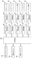
《全体的構成》
図1は、本実施形態のコルゲートマシン1における多数の加工装置の全体的構成を示す正面図である。図1において、コルゲートマシン1の加工エンドは、ダブルフェーサ10の出口から下流側に延びる搬送経路PLに沿って、ロータリーシャ20、スリッタスコアラ30、カットオフ装置40、およびスタッカ装置50を備える。ダブルフェーサ10は、シングルフェーサにより生産された片面段ボールに表ライナを貼り合わせて両面段ボールを形成する。ダブルフェーサ10は、上部ベルト11および下部ベルト12を備え、両ベルトにより両面段ボールを上下から挟持して搬送する。上部ベルト11および下部ベルト12は、駆動モータ13に連結された上部プーリ14および下部プーリ15によりそれぞれ駆動される。本実施形態のコルゲートマシン1において、オーダ変更によりフルートの種類が異なる両面段ボールが生産される場合には、シングルフェーサの公知の段ロールがフルートの種類に合わせて自動または手動操作で交換される。
<Overall configuration>
FIG. 1 is a front view showing an overall configuration of a number of processing apparatuses in the
〈加工エンドの構成〉
ロータリーシャ20は、ダブルフェーサ10の下流側に配置され、オーダ変更時に、両面段ボールを搬送方向FDと直交する幅方向に全幅切断する。ロータリーシャ20は、上下に対向配置されたナイフシリンダ21とアンビルシリンダ22と備える。ナイフシリンダ21の周面には、幅方向に延びるナイフが設けられる。アンビルシリンダ22は、ナイフシリンダ21のナイフと係合する受部を有する。両シリンダ21、22が回転すると、ナイフと受部とが係合して両面段ボールが幅方向に切断される。
<Processing end configuration>
The
スリッタスコアラ30は、本発明のスリッタが具体化されたものであり、所定の幅を持つように両面段ボールを搬送方向FDに切断すると共に、搬送方向FDに延びる罫線を施すものである。スリッタスコアラ30は、搬送方向FDに沿って配列された第1のユニット30Aと第2のユニット30Bとから構成されている。第1および第2のユニット30A、30Bは、一方が稼動中に、他方は、オーダ変更のために幅方向の加工位置の切り替えなどの準備作業を行なうように構成される。
The
第1のユニット30Aは、搬送方向FDに沿って配列された上流側スコアラ31Aおよび下流側スコアラ32Aを備える。各スコアラは、搬送経路PLの上方に配置された上罫線ロールと、搬送経路PLの下方に配置された下罫線ロールとの組を幅方向に多数組有する。上罫線ロールおよび下罫線ロールは、各オーダに従って指定される罫線加工位置に位置決めされるように、幅方向に移動可能にそれぞれ構成される。
The
下流側スコアラ32Aの下流側には、第1のスリッタ33Aが配置される。第1のスリッタ33Aは、搬送経路PLの上方に配置されたナイフ受け部材330Aと、搬送経路PLの下方に配置されたスリッタナイフ331Aとの組を幅方向に多数組有する。ナイフ受け部材330Aおよびスリッタナイフ331Aは、各オーダに従って指定されるスリット加工位置に位置決めされるように、幅方向に移動可能にそれぞれ構成される。
A
各オーダに従う所定幅に両面段ボールをスリット加工するために多数組のスリッタの中の複数組のスリッタが選択的に作動され、幅方向において位置決めされる。また、各オーダに従う幅方向の間隔で罫線加工するために多数のスコアラの中の複数のスコアラが選択的に作動され、幅方向において位置決めされる。スコアラ31A、32Aおよびスリッタ33Aが駆動されると、各オーダに従って位置決めされた幅方向の所定位置に、スリットおよび罫線の加工が両面段ボールに施される。
In order to slit a double-sided cardboard to a predetermined width according to each order, a plurality of slitters among a plurality of slitters are selectively operated and positioned in the width direction. In addition, a plurality of scorers among a large number of scorers are selectively operated and positioned in the width direction in order to perform ruled line processing at intervals in the width direction according to each order. When the
第2のユニット30Bも、第1のユニット30Aと同様に構成され、2組のスコアラ31B、32Bと、第2のスリッタ33Bとを備える。図1では、第2のユニット30Bが準備状態にあり、上下の罫線ロールが互いに離間すると共に、ナイフ受け部材330Bとスリッタナイフ331Bとが互いに離間している。本実施形態のナイフ受け部材330A、330Bおよびスリッタナイフ331A、331Bが、本発明のナイフ受け部材およびスリッタナイフの一例である。本実施形態の第1および第2のユニット30A、30Bが、本発明の第1および第2のスリッタユニットの一例である。
The
カットオフ装置40は、スリッタスコアラ30によって搬送方向FDに切断された両面段ボールを幅方向に切断し、板状の段ボールシートを形成する。カットオフ装置40は、上下に対向配置された上ナイフシリンダ41および下ナイフシリンダ42を有する。両ナイフシリンダ41、42が回転してナイフが噛合うことにより、両面段ボールが幅方向に切断される。カットオフ装置40は、供給側コンベア43および送出側コンベア44を有する。供給側コンベア43は、連続する両面段ボールを両ナイフシリンダ41、42に供給し、送出側コンベア44は両ナイフシリンダのナイフにより切断された段ボールシートを送出する。両コンベア43、44の搬送速度は、両ナイフシリンダ41、42の回転速度と同期している。
The cut-off
スタッカ装置50は、送出側コンベア44から搬送コンベア51により搬送された段ボールシートを積み上げ、製品として機外に排出する。スタッカ装置50は、各オーダに従うサイズの段ボールシートを積載するために最適なパレットを自動的に選択するように構成される。また、スタッカ装置50は、積載される段ボールシートの積載位置を規制するフロントストッパを、各オーダに従う段ボールシートのサイズに応じて自動的に位置決めするように構成される。
The
〈サクションコンベアの構成〉
ロータリーシャ20からカットオフ装置40までの間において、連続する両面段ボールを搬送するためにサクションコンベア群60が配置される。サクションコンベア群60は、第1ないし第3のサクションコンベア61、62、63からなる。第1のサクションコンベア61は、コンベアユニット61Aと、ブロアユニット61Bとを有する。コンベアユニット61Aは、連続する両面段ボールを搬送方向FDに搬送する構成であり、ブロアユニット61Bは、コンベアユニット61Aにより搬送される両面段ボールを下方に吸引して両面段ボールをコンベアユニット61Aの搬送表面に吸着させる作用を有する。第2および第3のサクションコンベア62、63も、第1のサクションコンベア61と同様に構成され、コンベアユニット62A、63Aと、ブロアユニット62B、63Bとを有する。コンベアユニット61A、62A、63Aは、駆動モータ64にそれぞれ連結され、駆動モータ64の回転により、同期した搬送速度で両面段ボールを搬送するように構成される。
<Configuration of suction conveyor>
Between the
〈スリッタスコアラ30の詳細な構成〉
本実施形態のスリッタスコアラ30は、第1および第2のユニット30A、30Bを備えるが、両ユニット30A、30Bは同じ構成であるので、第1のユニット30Aの構成について、主に図2および図3を参照して詳細に説明する。
<Detailed configuration of
The
(スコアラ31A、32Aの構成)
本実施形態では、隣り合う罫線の間隔を可能な限り小さくできるように、2組のスコアラ31A、32Aが搬送方向FDに配列される。上流側スコアラ31Aは、上罫線ロール310Aと、下罫線ロール311Aとを有する。上罫線ロール310Aの円周面の略中央には、円周方向に連続した凸部が形成される。下罫線ロール311Aの円周面の略中央には、円周方向に連続した凹部が形成される。下罫線ロール311Aは、その円周面が搬送経路PLの上面と一致するように固定されて配置される。一方、上罫線ロール310Aは、後述するように、搬送経路PLに対して上下方向に変位可能に支持される。下流側スコアラ32Aも、上流側スコアラ31Aと同様に構成され、上罫線ロール320Aと、下罫線ロール321Aとを有する。本実施形態のスコアラ31A、32A、上罫線ロール310A、320Aおよび下罫線ロール311A、321Aが、本発明のスコアラ、上罫線ロールおよび下罫線ロールの一例である。また、本実施形態の円周方向に連続した凸部が、本発明の加工突条部の一例である。
(Configuration of
In the present embodiment, two sets of
図3において、第1のユニット30Aは、前後に対向する一対のフレーム400、401を有する。図2において、一対の上方梁402、403、および一対の下方梁404、405が、両フレーム400、401の間にそれぞれ架設される。また、搬送方向FDと直交する幅方向、すなわち前後方向に下罫線ロール311A、321Aを案内するために、ガイド梁406が、両フレーム400、401の間に架設される。回転駆動モータ407が、図3に示すようにフレーム401に固定される。
In FIG. 3, the
一対の下方支持ブロック408、409は、下罫線ロール311A、321Aを回転可能にそれぞれ支持し、ガイド梁406に沿って前後方向に摺動可能に取り付けられる。両下方支持ブロック408、409は、各ブロック自体を前後方向に摺動させるための幅方向駆動モータ410、411をそれぞれ搭載する。幅方向駆動モータ410、411は、両フレーム400、401の間に架設された一対のネジ軸412、413と螺合する回転体にそれぞれ連結される。両下方支持ブロック408、409は、両駆動モータ410、411の回転駆動により、ガイド梁406に沿って前後方向に移動する。両下罫線ロール311A、321Aは、両フレーム400、401の間に架設された一対の回転駆動軸414、415に、軸方向に移動自在にそれぞれ取り付けられる。両回転駆動軸414、415は、図3に示す回転駆動モータ407に公知の動力伝達機構を介して連結される。両下罫線ロール311A、321Aは、回転駆動モータ407の駆動により、図2において、反時計回りに回転する。
The pair of lower support blocks 408 and 409 support the lower ruled line rolls 311 </ b> A and 321 </ b> A in a rotatable manner, and are attached to be slidable in the front-rear direction along the
(上罫線ロール310A、320Aの上下動機構の構成)
図2において、上罫線ロール310A、320Aを上下方向に変位させるために、ロール上下動インダクションモータ416およびスクリュージャッキ417が、上方梁402上に固定される。スクリュージャッキ417は、入力軸418と、出力軸419とを有し、入力軸418に伝達された回転運動を、出力軸419の軸方向の直線運動に変換する装置である。入力軸418は、インダクションモータ416にタイミングベルト420およびプーリを介して連結される。スクリュージャッキ417としては、株式会社ツバキエマソン製の「リニパワージャッキ」を使用することができる。本実施形態では、2つのスクリュージャッキ417が、上方梁402の前後両端部分に近接して固定され、入力軸418を共通の入力軸として構成される。
(Configuration of vertical movement mechanism of upper ruled line rolls 310A and 320A)
In FIG. 2, a roll vertical
出力軸419の下端部は、前後方向に延びる可動ガイド体421の上端部に連結される。可動ガイド体421の前後両端部は、両フレーム400、401の対向面に設けられたガイド部材により案内されて上下方向に移動可能である。一対の上方支持ブロック422、423は、可動ガイド体421に沿って前後方向に摺動可能に取り付けられる。両上方支持ブロック422、423は、各ブロック自体を前後方向に摺動させるための幅方向駆動モータ424、425をそれぞれ搭載する。幅方向駆動モータ424、425は、両フレーム400、401の間で可動ガイド体421と共に上下方向に移動可能に設けられた一対のネジ軸426、427と螺合する回転体にそれぞれ連結される。両上方支持ブロック422、423は、両駆動モータ424、425の回転駆動により、可動ガイド体421に沿って前後方向に移動する。
The lower end portion of the
一対の揺動レバー428、429が、両上方支持ブロック422、423の下方部分に揺動可能にそれぞれ設けられる。両上罫線ロール310A、320Aは、両揺動レバー428、429の自由端に回転可能にそれぞれ取り付けられる。両揺動レバー428、429は、側面から延出するアーム部430、431をそれぞれ有する。ロール作動エアシリンダ432が、上方支持ブロック422の上方部分とアーム部430との間に取り付けられ、ロール作動エアシリンダ433が、上方支持ブロック423の上方部分とアーム部431との間に取り付けられる。両揺動レバー428、429は、両フレーム400、401の間で可動ガイド体421と共に上下方向に移動可能に設けられた一対の回転駆動軸434、435に、軸方向および回転方向に移動自在にそれぞれ設けられる。両回転駆動軸434、435は、タイミングベルトおよびプーリを介して両上罫線ロール310A、320Aに連結される。両回転駆動軸434、435は、図3に示す回転駆動モータ407に公知のタイミングベルトおよび歯車機構からなる動力伝達機構を介して連結される。両上罫線ロール310A、320Aは、回転駆動モータ407の駆動により、図2において、時計回りに回転する。
A pair of
インダクションモータ416が回転駆動されると、その回転運動が、スクリュージャッキ417により直線運動に変換される。可動ガイド体421は、スクリュージャッキ417の出力軸419の上下動に従って、上下方向に変位して位置決めされる。可動ガイド体421が位置決めされた状態で、ロール作動エアシリンダ432、433が、作動または不作動とされることにより、両上罫線ロール310A、320Aは、両下罫線ロール311A、321Aに対して、接近または離間することができる。図2において、ロール作動エアシリンダ432が不作動状態にあり、ロール作動エアシリンダ433が作動状態にあることから、上罫線ロール310Aは、実線で示すように、下罫線ロール311Aから離間した位置、すなわち休止位置にあり、上罫線ロール320Aは、実線で示すように、下罫線ロール321Aに接近した位置、すなわち段ボールに罫線加工を行うことができる作動位置にある。反対に、ロール作動エアシリンダ432が作動状態に変化し、ロール作動エアシリンダ433が不作動状態に変化すると、上罫線ロール310Aは、2点鎖線で示すように、下罫線ロール311Aに接近した作動位置に移動し、上罫線ロール320Aは、2点鎖線で示すように、下罫線ロール321Aから離間した休止位置に移動する。
When the
本実施形態では、スコアラ31A、32Aを通過する段ボールを下方から支持するために、固定支持部材436が、両下罫線ロール311A、321Aの間で、搬送経路PLと同じ高さの位置に固定されて配置される。本実施形態のスクリュージャッキ417、可動ガイド体421、上方支持ブロック422、423、および揺動レバー428、429の組み合わせが、本発明のロール支持機構の一例である。
In the present embodiment, in order to support the corrugated cardboard passing through the
(スリッタ33Aの構成)
第1のスリッタ33Aは、ナイフ受け部材330Aと、スリッタナイフ331Aとを有する。ナイフ受け部材330Aの円周面の略中央には、円周方向に連続した溝が形成される。スリッタナイフ331Aは、薄い円盤状の回転式ナイフからなり、段ボールにスリット加工を行うときにナイフ受け部材330Aの溝に進入して噛み合うように構成される。ナイフ受け部材330Aおよびスリッタナイフ331Aは、後述するように、搬送経路PLに対して上下方向に変位可能に支持される。本実施形態では、図3に示すように、7つの第1のスリッタ33A−1〜33A−7が、前後方向に配列される。図2は、図3に1点鎖線で示すA−A線に従う断面図であり、図2には、図3に示す第1のスリッタ33A−5が、第1のスリッタ33Aとして例示される。
(Configuration of
The
(ナイフ受け部材330Aの上下動機構の構成)
ナイフ受け部材330Aの上下動機構は、インダクションモータおよびスクリュージャッキを備えた構成において、前述の上罫線ロール310A、320Aの上下動機構と共通しているが、エアシリンダを備えていない点で、上罫線ロール310A、320Aの上下動機構と相違する。
(Configuration of vertical movement mechanism of
The vertical movement mechanism of the
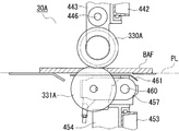
図2および図3において、ナイフ受け部材330Aを上下方向に変位させるために、ナイフ受け上下動インダクションモータ437および2つのスクリュージャッキ438A、438Bが、上方梁403上に固定される。両スクリュージャッキ438A、438Bは、スクリュージャッキ417と同じ構成であり、共通する入力軸439に伝達された回転運動を、出力軸440A、440Bの軸方向の直線運動にそれぞれ変換する装置である。入力軸439は、インダクションモータ437にタイミングベルト441およびプーリを介して連結される。
2 and 3, a knife receiver vertical
出力軸440A、440Bの下端部は、前後方向に延びる可動ガイド体442の上端部にそれぞれ連結される。可動ガイド体442の前後両端部は、両フレーム400、401の対向面に設けられたガイド部材により案内されて上下方向に移動可能である。上方支持ブロック443は、可動ガイド体442に沿って前後方向に摺動可能に取り付けられる。上方支持ブロック443は、ブロック自体を前後方向に摺動させるための幅方向駆動モータ444を搭載する。幅方向駆動モータ444は、両フレーム400、401の間で可動ガイド体442と共に上下方向に移動可能に設けられたネジ軸445と螺合する回転体に連結される。上方支持ブロック443は、駆動モータ444の回転駆動により、可動ガイド体442に沿って前後方向に移動する。
The lower end portions of the
ナイフ受け部材330Aは、上方支持ブロック443の下端部に回転可能に取り付けられる。上方支持ブロック443は、両フレーム400、401の間で可動ガイド体442と共に上下方向に移動可能に設けられた回転駆動軸446に、軸方向および回転方向に移動自在に設けられる。回転駆動軸446は、伝達ベルトおよびプーリを介してナイフ受け部材330Aに連結される。回転駆動軸446は、図3に示す回転駆動モータ407に公知のタイミングベルトおよび歯車機構からなる動力伝達機構を介して連結される。ナイフ受け部材330Aは、回転駆動モータ407の駆動により、図2において、時計回りに回転する。
The
インダクションモータ437が回転駆動されると、その回転運動が、スクリュージャッキ438A、438Bにより直線運動に変換される。可動ガイド体442は、スクリュージャッキ438A、438Bの出力軸440A、440Bの上下動に従って、上下方向に変位して位置決めされる。この可動ガイド体442の上下方向における位置決めにより、ナイフ受け部材330Aは、搬送経路PLに沿って搬送される段ボールの上面に対して、接触可能な作動位置、または離間した休止位置に変位する。本実施形態のスクリュージャッキ438A、438B、可動ガイド体442、および上方支持ブロック443の組み合わせが、本発明のナイフ受け支持機構の一例である。
When the
(スリッタナイフ331Aの上下動機構の構成)
スリッタナイフ331Aの上下動機構は、インダクションモータおよびスクリュージャッキと、エアシリンダとを備えた基本的構成において、前述の上罫線ロール310A、320Aの上下動機構と同じである。
(Configuration of the vertical movement mechanism of the
The vertical movement mechanism of the
図2において、スリッタナイフ331Aを上下方向に変位させるために、ナイフ上下動インダクションモータ447および2つのスクリュージャッキ448A、448Bが、下方梁405の下面に固定される。スクリュージャッキ448A、448Bは、共通する入力軸450と、出力軸451A、451Bとを有し、入力軸450に伝達された回転運動を、出力軸451A、451Bの軸方向の直線運動にそれぞれ変換する装置である。入力軸450は、インダクションモータ447にタイミングベルト452およびプーリを介して連結される。
In FIG. 2, a knife vertical
出力軸451A、451Bの上端部は、前後方向に延びる可動ガイド体453の下端部に連結される。可動ガイド体453の前後両端部は、両フレーム400、401の対向面に設けられたガイド部材により案内されて上下方向に移動可能である。下方支持ブロック454は、可動ガイド体453に沿って前後方向に摺動可能に取り付けられる。下方支持ブロック454は、ブロック自体を前後方向に摺動させるための幅方向駆動モータ455を搭載する。幅方向駆動モータ455は、両フレーム400、401の間で可動ガイド体453と共に上下方向に移動可能に設けられたネジ軸456と螺合する回転体に連結される。下方支持ブロック454は、駆動モータ455の回転駆動により、可動ガイド体453に沿って前後方向に移動する。
The upper ends of the
揺動レバー457が、下方支持ブロック454の上方部分に揺動可能に設けられる。両スリッタナイフ331Aは、揺動レバー457の自由端に回転可能に取り付けられる。揺動レバー457は、側面から延出するアーム部458を有する。ナイフ作動エアシリンダ459が、下方支持ブロック454の下方部分とアーム部458との間に取り付けられる。揺動レバー457は、両フレーム400、401の間で可動ガイド体453と共に上下方向に移動可能に設けられた回転駆動軸460に、軸方向および回転方向に移動自在に設けられる。回転駆動軸460は、伝達ベルトおよびプーリを介してスリッタナイフ331Aに連結される。回転駆動軸460は、図3に示す回転駆動モータ407に公知のタイミングベルトおよび歯車機構からなる動力伝達機構を介して連結される。スリッタナイフ331Aは、回転駆動モータ407の駆動により、図2において、反時計回りに回転する。
A
インダクションモータ447が回転駆動されると、その回転運動が、スクリュージャッキ448A、448Bにより直線運動に変換される。可動ガイド体453は、スクリュージャッキ448A、448Bの出力軸451A、451Bの上下動に従って、上下方向に変位して位置決めされる。可動ガイド体453が位置決めされた状態で、ナイフ作動エアシリンダ459が、作動または不作動とされることにより、スリッタナイフ331Aは、ナイフ受け部材330Aに対して、接近または離間することができる。図2において、ナイフ作動エアシリンダ459が不作動状態にあることから、スリッタナイフ331Aは、実線で示すように、ナイフ受け部材330Aから離間した位置、すなわち休止位置にある。反対に、ナイフ作動エアシリンダ459が作動状態に変化すると、スリッタナイフ331Aは、2点鎖線で示すように、ナイフ受け部材330Aに接近して噛み合う作動位置に移動する。
When the
本実施形態では、第1のスリッタ33Aを通過する段ボールを下方から支持するために、可動支持部材461が、揺動レバー457の揺動支点に近接した位置に固定される。下方支持ブロック453が、インダクションモータ447の回転駆動により上下方向に変位すると、可動支持部材461も、搬送経路PLに対して上下方向に移動する。さらに、ナイフ作動エアシリンダ459が作動状態にあると、可動支持部材461は、搬送経路PLにさらに接近した位置に移動する。この状態で、可動支持部材461は、段ボールを下方から支持することができる。本実施形態のスクリュージャッキ448A、448B、可動ガイド体453、下方支持ブロック454、および揺動レバー457の組み合わせが、本発明のナイフ支持機構の一例であり、下方支持ブロック454が、本発明の可動体の一例で、揺動レバーが、本発明の支持体の一例である。また、本実施形態の可動支持部材461が、本発明の支持部材の一例である。
In the present embodiment, the
(パルス発生器の構成および配置)
本実施形態では、上方支持ブロック422、423、上方支持ブロック443、および下方支持ブロック454の上下方向の位置を検出するために、3つのパルス発生器が、入力軸418、439、450に作動的に連結される。図4において、上方支持ブロック443の上下方向の位置を検出するためのパルス発生器462が、入力軸439と歯車列を介して連結され、入力軸439の回転量および回転方向に応じたパルス信号を発生するように構成される。下方支持ブロック454の上下方向の位置を検出するためのパルス発生器463も、図3に示すように、入力軸450と歯車列を介して連結される。上方支持ブロック422、423の上下方向の位置を検出するためのパルス発生器も、パルス発生器462と同様に、入力軸418に連結される。
(Configuration and arrangement of pulse generator)
In this embodiment, three pulse generators are actuated on the
第2のユニット30Bも、上述した第1のユニット30Aと同様に、インダクションモータおよびエアシリンダの駆動により上下方向に変位するように構成される。すなわち、図6に示すように、2つのスコアラ31B、32Bの上罫線ロール310B、320Bは、ロール上下動インダクションモータ464、およびロール作動エアシリンダ465、466の駆動により、上下方向にそれぞれ変位する。第2のスリッタ33Bのナイフ受け部材330Bは、ナイフ受け上下動インダクションモータ467の駆動により、上下方向に変位する。第2のスリッタ33Bのスリッタナイフ331Bは、ナイフ上下動インダクションモータ468、およびナイフ作動エアシリンダ469の駆動により、上下方向に変位する。
Similarly to the
《電気的構成》
本実施形態のコルゲートマシン1の電気的構成について、添付図面を参照して以下に説明する。図5は、コルゲートマシン1の電気的構成を示すブロック図である。図5において、管理装置100は、両面段ボールシートを生産するために、生産エンドおよび加工エンドの各装置の動作全般を監視して、連続する複数のオーダについて両面段ボールシートの生産数量を管理する装置である。生産エンドの各装置の制御動作は、すでに公知であり、本発明と関係しないことから、生産エンドの各装置を制御する制御装置の構成について、その説明を省略し、図5には示されていない。
<Electrical configuration>
The electrical configuration of the
〈メモリの構成〉
管理プログラムメモリ110は、管理装置100がコルゲートマシン1を制御するために主制御ルーチンプログラムおよび所定の設定値などを固定記憶するメモリである。たとえば、所定の設定値は、コルゲートマシン1の構成などから定まる固有の設定値である。管理作業メモリ120は、管理装置100が主制御ルーチンプログラムを実行する際に処理した演算処理結果を一時記憶するメモリである。管理データメモリ130は、連続する複数のオーダの生産管理計画を書き換え可能に固定記憶するメモリであり、ハードディスクから構成される。管理装置100は、管理プログラムメモリ110および管理作業メモリ120などの記憶手段と共にコンピュータを構成している。
<Memory configuration>
The
〈制御装置および駆動装置の構成〉
ダブルフェーサ10、ロータリーシャ20、スリッタスコアラ30、カットオフ装置40、およびスタッカ装置50を駆動または停止すると共に、その駆動速度を個別に制御するために、ダブルフェーサ制御装置140、ロータリーシャ制御装置141、スリッタスコアラ制御装置142、カットオフ制御装置143、およびスタッカ制御装置144が備えられる。これらの制御装置140〜144は、管理装置100からの指令に従って制御動作を行うと共に、現在の制御状態を管理装置100に通知するために管理装置100にそれぞれ接続される。ダブルフェーサ駆動装置150、ロータリーシャ駆動装置151、スリッタスコアラ駆動装置152、カットオフ駆動装置153、およびスタッカ駆動装置154は、制御装置140〜144からの制御命令に従って、ダブルフェーサ10、ロータリーシャ20、スリッタスコアラ30、カットオフ装置40、およびスタッカ装置50をそれぞれ駆動するもので、駆動モータおよび位置決めインダクションモータを備える。ダブルフェーサ駆動装置150は、上部プーリ14および下部プーリ15を駆動する駆動モータ13を有する。
<Configuration of control device and drive device>
In order to drive or stop the
ロータリーシャ制御装置141は、管理装置100からの追跡指令に従って両面段ボール上のオーダ変更位置を追跡するために、公知の測定器と接続される。カットオフ制御装置143は、管理装置100からの追跡指令に従って、各オーダに応じたシート長さの搬送を追跡すると共に、ロータリーシャ20により切断された両面段ボールの搬送を追跡するために、公知の測定器と接続される。
The rotary
〈スリッタスコアラ制御装置142の詳細な構成〉
スリッタスコアラ制御装置142は、第1および第2のユニット30A、30Bを構成するスコアラおよびスリッタの回転駆動と、幅方向移動とを制御すると共に、上下方向の移動をも制御する。スコアラおよびスリッタの回転駆動と、幅方向移動との制御は、よく知られており、本発明と関係しないことから、この回転駆動および幅方向移動の制御と駆動とについては、説明を省略し、スコアラおよびスリッタの上下方向の移動の制御と駆動とについて、図6を参照して詳細に説明する。
<Detailed Configuration of Slitter
The slitter
スリッタスコアラ制御装置142は、第1のユニット制御装置200と、第2のユニット制御装置201とから主に構成される。第1のユニット制御装置200は、第1のユニット30Aの動作を制御し、第2のユニット制御装置201は、第2のユニット30Bの動作を制御する。スリッタスコアラプログラムメモリ202は、両ユニット制御装置200、201が実行する制御プログラム、および予め定められた設定値を固定記憶する。スリッタスコアラ作業メモリ203は、管理装置100から供給された制御指令および各種情報を一時記憶し、また制御プログラムの実行により処理された結果を一時記憶する。
The slitter
第1のユニット制御装置200は、上罫線ロール310A、320A、ナイフ受け部材330A、およびスリッタナイフ331Aの上下方向の位置を検知するためにパルス発生器群204と接続される。第2のユニット制御装置201は、上罫線ロール310B、320B、ナイフ受け部材330B、およびスリッタナイフ331Bの上下方向の位置を検知するためにパルス発生器群205と接続される。パルス発生器群204は、第1のユニット30Aに設けられたパルス発生器462、463を含み、3つのパルス発生器からなる。パルス発生器群205も、同様に、第2のユニット30Bに設けられた3つのパルス発生器からなる。
The
本実施形態では、制御プログラムとして、プログラムメモリ202は、図8に示すスリッタ上下動制御ルーチン、図7に示す上罫線ロール上下動制御ルーチンなどを記憶する。また、設定値として、プログラムメモリ202は、図9に示す位置指令テーブルを記憶する。本実施形態の第1および第2のユニット制御部200、201を含むスリッタスコアラ制御装置142が、本発明の制御部およびロール制御部の一例である。
In the present embodiment, the
(位置指令テーブルの記憶内容)
位置指令テーブルは、本実施形態のコルゲートマシン1により生産することができる段ボールのフルート種類であるAフルート〜Eフルートに対応して、スリッタナイフの作動位置指令値KS1〜KS4と、ナイフ受け部材の作動位置指令値RS1〜RS4および休止位置指令値RW1〜RW4と、上罫線ロールの作動位置指令値CS1〜CS4とを記憶する。位置指令テーブルの記憶内容について、図9および図10を参照して説明する。図10は、ナイフ受け部材330Aおよびスリッタナイフ331Aが、段ボールにスリット加工を行うことができる実線で示す作動位置と、段ボールから離間した2点鎖線で示す休止位置とにそれぞれ位置する状態を示す。図9において、スリッタナイフの作動位置指令値は、エアシリンダ459が作動されてスリッタナイフ331Aが図10に示す作動位置に位置するときに、スリッタナイフ331Aの上端部分と搬送経路PLの上面との距離KSDを指令する値である。ナイフ受け部材の作動位置指令値は、ナイフ受け部材330Aが図10に示す作動位置に位置するときに、ナイフ受け部材330Aの下端部分と搬送経路PLの上面との距離RSDを指令する値である。ナイフ受け部材の休止位置指令値は、ナイフ受け部材330Aが図10に示す休止位置に位置するときに、ナイフ受け部材330Aの下端部分と搬送経路PLの上面との距離RWDを指令する値である。
(Storage contents of position command table)
The position command table corresponds to A flute to E flute, which are corrugated cardboard flute types that can be produced by the corrugating
上罫線ロールの作動位置指令値は、エアシリンダ432またはエアシリンダ433が作動されて上罫線ロール310Aまたは上罫線ロール320Aが罫線加工を行うことができる作動位置に位置するときに、上罫線ロール310Aまたは上罫線ロール320Aの下端部分と搬送経路PLの上面との距離を指令する値である。
The upper ruled line roll operating position command value is such that when the
本実施形態では、スリッタナイフおよび上罫線ロールに関して休止位置指令値は、位置指令テーブルに記憶されていない。たとえば、スリッタナイフ331Aに関して、下方支持ブロック454の上下方向の可動範囲は、生産可能な段ボールの厚さの範囲に応じた範囲であり、エアシリンダ459の作動および不作動によりスリッタナイフ331Aが上下方向に移動する範囲よりも充分に小さく設定されている。このことから、下方支持ブロック454が可動範囲の最も上方の位置に位置している場合でも、スリッタナイフ331Aの上端部分は、エアシリンダ459の不作動により、搬送経路PLから降下して段ボールの搬送に支障のない位置まで退避することができる。すなわち、スリッタナイフ331Aの上端部分は、エアシリンダ459の不作動により、搬送経路PLの上面から図10に示す距離KWDだけ降下して段ボールから充分に離間した位置まで退避する。また、上罫線ロール310A、320Aに関しても、上方支持ブロック421が可動範囲の最も下方の位置に位置している場合でも、上罫線ロール310A、320Aは、エアシリンダ432、433の不作動により、搬送経路PL上に位置する最大厚さの段ボール、本実施形態では、Aフルートの段ボールの上面から上昇して段ボールの搬送に支障のない位置まで退避することができる。この結果、スリッタナイフおよび上罫線ロールに関しては、各部材に対応するエアシリンダを不作動にするだけで、スリッタナイフおよび上罫線ロールが段ボールから離間した休止位置に移動することから、スリッタナイフおよび上罫線ロールの休止位置指令値が、その作動位置指令値とは別に記憶される必要はない。この休止位置指令値が記憶される必要がない場合であっても、スリッタナイフおよび上罫線ロールの休止位置は、その作動位置指令値と、対応するエアシリンダを不作動にするシリンダ不作動指令とにより、指令されることが理解される。
In the present embodiment, the pause position command value for the slitter knife and the upper ruled line roll is not stored in the position command table. For example, regarding the
ナイフ受け部材の作動位置指令値は、各フルートの段ボールの厚さと、所定の作動許容値との合計値である。ナイフ受け部材の休止位置指令値は、各フルートの段ボールの厚さと、所定の休止許容値との合計値である。スリッタナイフの作動位置指令値は、ナイフ受け部材の作動位置指令値と、所定の噛合い量との合計値である。所定の噛合い量は、図10に示す距離KSDと距離RSDとの差分となり、通常は、一定の値に設定される。本実施形態では、作動許容値は、1mmに設定され、休止許容値は、3mmに設定されている。作動許容値1mmは、1層の両面段ボールを構成する2枚のライナ原紙および1枚の中芯原紙の厚みのばらつきの合計値であり、この作動許容値は、複数層の両面段ボールの場合には、両面段ボールを構成する多数のライナ原紙および多数の中芯原紙の厚さのばらつきの合計値となる。休止許容値3mmは、1層の両面段ボールを構成する2枚のライナ原紙および1枚の中芯原紙のすべてが同時に紙継ぎされたと仮定した場合に、各原紙の厚さと、各原紙の紙継ぎ用の両面テープの厚さとを、原紙の枚数分だけ合計した合計値に、上記の作動許容値1mmを加えた値である。この休止許容値の設定により、休止位置で回転が停止されているナイフ受け部材に両面段ボールの紙継ぎ部分が衝突して両面段ボールに大きな抵抗がかかることを防止することができる。本実施形態の所定の噛合い量が、本発明のナイフ受け部材とスリッタナイフとの係合量の一例である。 The operation position command value of the knife receiving member is the total value of the thickness of the corrugated cardboard of each flute and a predetermined allowable operation value. The rest position command value of the knife receiving member is the total value of the corrugated cardboard thickness of each flute and a predetermined rest allowable value. The operating position command value of the slitter knife is a total value of the operating position command value of the knife receiving member and a predetermined meshing amount. The predetermined meshing amount is a difference between the distance KSD and the distance RSD shown in FIG. 10, and is usually set to a constant value. In this embodiment, the operation allowable value is set to 1 mm, and the pause allowable value is set to 3 mm. The allowable operating value of 1 mm is the total thickness variation of the two liner base papers and the single core base paper constituting one double-sided corrugated cardboard. Is a total value of thickness variations of a large number of liner base papers and a large number of core base papers constituting the double-sided cardboard. The pause allowance of 3 mm is the thickness of each base paper and the splicing of each base paper, assuming that all two liner base papers and one core base paper constituting a single-layer double-sided cardboard are spliced simultaneously. This is a value obtained by adding the above-described allowable operation value of 1 mm to the total value obtained by adding the thicknesses of the double-sided adhesive tapes for the number of base papers. By setting the rest allowable value, it is possible to prevent the paper joint portion of the double-sided cardboard from colliding with the knife receiving member whose rotation is stopped at the pause position and applying a large resistance to the double-sided cardboard. The predetermined meshing amount of the present embodiment is an example of the engagement amount between the knife receiving member and the slitter knife of the present invention.
本実施形態のスリッタスコアラプログラムメモリ202の位置指令テーブルが、本発明の情報取得部および記憶部の一例である。本実施形態の位置指令テーブルに記憶されたナイフ受け部材330Aおよびスリッタナイフ331Aの作動位置指令値RS1〜RS4、KS1〜KS4が、本発明のナイフ受け作動位置およびナイフ作動位置をそれぞれ指示するナイフ受け作動位置情報およびナイフ作動位置情報の一例であり、本実施形態のナイフ受け部材330Aの休止位置指令値RW1〜RW4が、本発明のナイフ受け休止位置を指示する休止位置情報の一例である。本実施形態のスリッタナイフ331Aの作動位置指令値KS1〜KS4とエアシリンダ459の不作動を指令するシリンダ不作動指令との組み合わせが、本発明のナイフ休止位置を指示する休止位置情報の一例である。
The position command table of the slitter
〈スリッタスコアラ駆動装置152の詳細な構成〉
スリッタスコアラ駆動装置152は、第1のユニット制御装置200により制御されるナイフ受け上下動駆動回路210、ナイフ上下動駆動回路211、およびロール上下動駆動回路212を含むと共に、第2のユニット制御装置201により制御されるナイフ受け上下動駆動回路213、ナイフ上下動駆動回路214、およびロール上下動駆動回路215を含む。
<Detailed Configuration of Slitter
The slitter
ナイフ受け上下動駆動回路210は、第1のユニット制御装置200からナイフ受け部材330Aの上下方向の位置に関する位置指令値および駆動制御指令を受けて、ナイフ受け上下動インダクションモータ437を駆動する。本実施形態では、第1のユニット制御装置200、ナイフ受け上下動駆動回路210、ナイフ受け上下動インダクションモータ437、およびパルス発生器群204は、ナイフ受け部材330Aの上下方向における位置決めをフィードバック制御する制御ループを構成する。他の駆動回路211〜215も、ナイフ受け上下動駆動回路210と同様に、フィードバック制御する制御ループの一部を構成する。ナイフ上下動駆動回路211は、第1のユニット制御装置200から、スリッタナイフ331Aの上下方向の位置に関する位置指令値および駆動制御指令と、スリッタナイフ331Aの作動および不作動を指令する作動制御指令とを受けて、ナイフ上下動インダクションモータ447を駆動すると共に、ナイフ作動エアシリンダ459を作動させる。ロール上下動駆動回路212は、第1のユニット制御装置200から、上罫線ロール310A、320Aの上下方向の位置に関する位置指令値および駆動制御指令と、上罫線ロール310A、320Aの作動および不作動を指令する作動制御指令とを受けて、ロール上下動インダクションモータ416を駆動すると共に、2つのロール作動エアシリンダ432、433をそれぞれ作動させる。
The knife receiver vertical
ナイフ受け上下動駆動回路213は、第2のユニット制御装置201らナイフ受け部材330Bの上下方向の位置に関する位置指令値および駆動制御指令を受けて、ナイフ受け上下動インダクションモータ467を駆動する。ナイフ上下動駆動回路214は、第2のユニット制御装置201から、スリッタナイフ331Bの上下方向の位置に関する位置指令値および駆動制御指令と、スリッタナイフ331Bの作動および不作動を指令する作動制御指令とを受けて、ナイフ上下動インダクションモータ468を駆動すると共に、ナイフ作動エアシリンダ469を作動させる。ロール上下動駆動回路215は、第2のユニット制御装置201から、上罫線ロール310B、320Bの上下方向の位置に関する位置指令値および駆動制御指令と、上罫線ロール310B、320Bの作動および不作動を指令する作動制御指令とを受けて、ロール上下動インダクションモータ464を駆動すると共に、2つのロール作動エアシリンダ465、466をそれぞれ作動させる。本実施形態のナイフ受け上下動インダクションモータ437、467とナイフ受け上下動駆動回路210、213とを含むスリッタスコアラ駆動装置152が、本発明のナイフ受け駆動部の一例であり、本実施形態のナイフ上下動インダクションモータ447、468、ナイフ作動エアシリンダ459、469、およびナイフ上下動駆動回路211、214を含むスリッタスコアラ駆動装置152が、本発明のナイフ駆動部の一例である。また、本実施形態のロール上下動インダクションモータ416、464、ロール作動エアシリンダ432、433、465、466、およびロール上下動駆動回路212、215を含むスリッタスコアラ駆動装置152が、本発明のロール駆動部の一例である。
The knife receiver vertical movement drive circuit 213 receives the position command value and the drive control command regarding the vertical position of the
《実施形態の動作および作用》
本実施形態のコルゲートマシン1の動作および作用について、図7および図8を参照して以下に説明する。一般に、連続する複数のオーダに従って、コルゲートマシンが異なる種類のフルートの段ボールを順次生産することは、よく知られていることから、異なる種類のフルートを生産する動作の説明は省略し、本発明のスリッタに関係するスリッタスコアラ30の動作を主に説明する。
<< Operation and Action of Embodiment >>
The operation and action of the
コルゲートマシン1が、Aフルート〜Eフルートの段ボールの中で、最も薄いEフルートの段ボールを(N−1)番目のオーダに従って生産し、最も厚いAフルートの段ボールをN番目のオーダに従って生産し、薄いCフルートの段ボールを(N+1)番目のオーダに従って生産し、Cフルートより厚くAフルートより薄いBフルートの段ボールを(N+2)番目のオーダに従って生産することを前提に、スリッタスコアラ30の動作を以下に説明する。
Corrugating
〈Aフルートの段ボールへの加工動作〉
管理データメモリ130に記憶された生産管理計画の中で、N番目のオーダの実行が開始される際に、スリッタスコアラ30は、N番目のオーダに従うスリット加工位置および罫線加工位置に、第1および第2のユニット30A、30Bのいずれかのスコアラおよびスリッタを幅方向に移動して位置決めすると共に、上下方向に移動して位置決めする。本実施形態では、図1に示すように、第1のユニット30Aが、N番目のオーダを実行するために稼働し、第2のユニット30Bは休止するものとして説明する。スコアラおよびスリッタを幅方向に位置決めする動作は、よく知られていることから、幅方向の位置決め動作の説明は省略し、上下方向の位置決め動作について詳細に以下に説明する。
<Processing of A flute into corrugated cardboard>
When the execution of the Nth order is started in the production management plan stored in the
(スコアラの上下方向の位置決め動作)
スコアラ31A、32Aを上下方向に位置決めするために、スリッタスコアラプログラムメモリ202に記憶された上罫線ロール上下動制御ルーチンが、管理装置100からのオーダ変更指令に従って、第1および第2のユニット制御装置200、201によって実行される。これにより、図7に示す上罫線ロール上下動制御ルーチンの実行が開始される。
(Scorer vertical positioning)
In order to position the
先のオーダから2つ後のオーダのフルート種類に対応した上罫線ロールの作動位置指令値が、位置指令テーブルから読み出され、スリッタスコアラ作業メモリ203に一時記憶される(SA1)。この場合、先のオーダから2つ後のオーダは、先のオーダである(N−1)番目のオーダから2つ後の(N+1)番目のオーダである。(N+1)番目のオーダはCフルートに関するオーダであるから、Cフルートに対応した作動位置指令値CS3が位置指令テーブルから読み出される。 The operation position command value of the upper ruled line roll corresponding to the flute type of the second order after the previous order is read from the position command table and temporarily stored in the slitter scorer work memory 203 (SA1). In this case, the second order after the previous order is the (N + 1) th order that is two orders after the (N-1) th order that is the previous order. Since the (N + 1) th order is an order related to the C flute, the operation position command value CS3 corresponding to the C flute is read from the position command table.
先のオーダを実行したユニットの上罫線ロールの作動位置指令値が、ステップSA1において記憶された作動位置指令値CS3に設定され、作業メモリ203に記憶される(SA2)。この場合、先のオーダを実行したユニットは、第2のユニット30Bであることから、そのユニット30Bの上罫線ロール310B、320Bの作動位置指令値が設定される。
The operation position command value of the upper ruled line roll of the unit that executed the previous order is set to the operation position command value CS3 stored in step SA1, and stored in the work memory 203 (SA2). In this case, since the unit that executed the previous order is the
切替指令が、管理装置100から第1および第2のユニット制御装置200、201に送出されたか否かが判断される(SA3)。切替指令が送出されない場合(SA3:NO)は、ステップSA3の判断が繰り返し実行される。切替指令が送出されると(SA3:YES)、処理がステップSA4に進む。切替指令は、先のオーダを実行したユニットの上罫線ロールが、段ボールから離間した休止位置に移動し、後のオーダを実行するユニットの上罫線ロールが、段ボールの加工を行うことができる作動位置に移動することを指令するものである。
It is determined whether or not a switching command has been sent from the
先のオーダを実行したユニットの上罫線ロールが、エアシリンダの不作動により休止位置に移動し、その後に、設定された作動位置指令値CS3に従って位置決めされる(SA4)。具体的には、第2のユニット制御装置201が、切替指令に基づいてシリンダ不作動指令を発生し、このシリンダ不作動指令に従ってロール上下動駆動回路215を動作させ、図6に示すロール作動エアシリンダ465、466を不作動にする。その後に、第2のユニット制御装置201が、ステップSA2において設定された(N+1)番目のオーダに従う作動位置指令値CS3に従ってロール上下動駆動回路215を動作させ、図6に示すロール上下動インダクションモータ464の駆動を制御する。これにより、上罫線ロール310B、320Bは、搬送経路PLから上方の位置に移動し、段ボールの搬送に支障のない休止位置まで退避することができる。
The upper ruled line roll of the unit that executed the previous order moves to the rest position due to the non-operation of the air cylinder, and is then positioned according to the set operation position command value CS3 (SA4). Specifically, the second
後のオーダを実行するユニットの上罫線ロールが、エアシリンダの作動により作動位置に移動する(SA5)。この場合、オーダの内容に応じて、上罫線ロール310A、320Aの両ロールが罫線加工に使用される場合と、図2に示すように一方のロールのみが罫線加工に使用される場合とがある。本実施形態では、一方のロールのみが使用されるものとして説明する。具体的には、後のオーダであるN番目のオーダを実行する第1のユニット30Aを制御する第1のユニット制御装置200が、切替指令に基づいてシリンダ作動指令を発生し、このシリンダ作動指令に従ってロール上下動駆動回路212を動作させ、ロール作動エアシリンダ433を作動させ、ロール作動エアシリンダ432を不作動にする。このとき、第1のユニット30Aの上罫線ロール320Aは、前回実行されたステップSA4において、作動位置指令値CS1に従って、すでに位置決めされている。このため、上罫線ロール320Aは、エアシリンダ433の作動のみにより、下罫線ロール321Aに接近した作動位置に移動し、上罫線ロール310Aは、エアシリンダ432の不作動のみにより、下罫線ロール311Aから離間した休止位置に位置する。この状態で、上罫線ロール320Aおよび下罫線ロール321Aは、Aフルートの段ボールに罫線加工を行うことができる。上罫線ロール320Aは、Aフルートの段ボールBAFの厚さに対応した作動位置に位置決めされることにより、上罫線ロール320Aは段ボールBAFの上面において適切な深さの罫線を施すことができ、段ボールを損傷させることを防止することができる。
The upper ruled line roll of the unit that executes the subsequent order is moved to the operating position by the operation of the air cylinder (SA5). In this case, depending on the contents of the order, both the upper ruled line rolls 310A and 320A may be used for ruled line processing, or only one roll may be used for ruled line processing as shown in FIG. . In the present embodiment, description will be made assuming that only one roll is used. Specifically, the first
(スリッタの上下方向の位置決め動作)
スリッタ33Aのナイフ受け部材330Aおよびスリッタナイフ331Aを上下方向に位置決めするために、スリッタスコアラプログラムメモリ202に記憶されたスリッタ上下動制御ルーチンが、管理装置100からのオーダ変更指令に従って、第1および第2のユニット制御装置200、201によって実行される。これにより、図8に示すスリッタ上下動制御ルーチンの実行が開始される。
(Slitter vertical positioning operation)
In order to position the
図8において、先のオーダのフルート種類に対応した位置指令値が、位置指令テーブルから読み出され、スリッタスコアラ作業メモリ203に一時記憶される(SB1)。この場合、先のオーダは、これから実行されるN番目のオーダより先の(N−1)番目のオーダである。(N−1)番目のオーダは、Eフルートに関するオーダであるから、Eフルートに対応したスリッタナイフの作動位置指令値KS4と、ナイフ受け部材の休止位置指令値RW4とが、位置指令テーブルから読み出される。 In FIG. 8, the position command value corresponding to the flute type of the previous order is read from the position command table and temporarily stored in the slitter scorer work memory 203 (SB1). In this case, the previous order is the (N−1) th order ahead of the Nth order to be executed. Since the (N-1) th order is an order related to the E flute, the operation position command value KS4 of the slitter knife corresponding to the E flute and the rest position command value RW4 of the knife receiving member are read from the position command table. It is.
後のオーダのフルート種類に対応した位置指令値が、位置指令テーブルから読み出され、スリッタスコアラ作業メモリ203に一時記憶される(SB2)。この場合、後のオーダは、これから実行されるN番目のオーダである。N番目のオーダは、Aフルートの段ボールを加工するオーダであることから、Aフルートに対応したスリッタナイフの作動位置指令値KS1と、ナイフ受け部材の休止位置指令値RW1とが、位置指令テーブルから読み出される。 The position command value corresponding to the flute type of the subsequent order is read from the position command table and temporarily stored in the slitter scorer work memory 203 (SB2). In this case, the subsequent order is the Nth order to be executed. Since the Nth order is an order for processing the corrugated cardboard of the A flute, the slitter knife operating position command value KS1 corresponding to the A flute and the rest position command value RW1 of the knife receiving member are obtained from the position command table. Read out.
先のオーダを実行したユニットのナイフ受け部材の休止位置指令値が、大きい休止位置指令値に設定され、作業メモリ203に一時記憶される(SB3)。この場合、先のオーダを実行したユニットは、第1のユニット30AがN番目のオーダを実行する予定であることから、第2のユニット30Bである。大きい休止位置指令値は、先のオーダである(N−1)番目のオーダと、後のオーダであるN番目のオーダとの間で、より大きい休止位置指令値であるが、この段階では、最も厚い段ボールであるAフルートに関する休止位置指令値RW1が最も大きな休止位置指令値であることから、大きい休止位置指令値は、休止位置指令値RW1である。
The rest position command value of the knife receiving member of the unit that executed the previous order is set to a large rest position command value, and is temporarily stored in the work memory 203 (SB3). In this case, the unit that executed the previous order is the
先のオーダを実行したユニットのスリッタナイフの作動位置指令値が、大きい作動位置指令値に設定され、作業メモリ203に一時記憶される(SB4)。大きい作動位置指令値は、先のオーダである(N−1)番目のオーダと、後のオーダであるN番目のオーダとの間で、より大きい作動位置指令値であるが、この段階では、最も厚い段ボールであるAフルートに関する作動位置指令値KS1が最も大きな作動位置指令値であることから、大きい作動位置指令値は、作動位置指令値KS1である。 The operating position command value of the slitter knife of the unit that executed the previous order is set to a large operating position command value, and is temporarily stored in the work memory 203 (SB4). The large operating position command value is a larger operating position command value between the (N-1) th order which is the previous order and the Nth order which is the subsequent order, but at this stage, Since the operation position command value KS1 for the A flute, which is the thickest cardboard, is the largest operation position command value, the large operation position command value is the operation position command value KS1.
待機指令が、管理装置100から第1および第2のユニット制御装置200、201に送出されたか否かが判断される(SB5)。待機指令が送出されない場合(SB5:NO)は、ステップSB5の判断が繰り返し実行される。待機指令が送出されると(SB5:YES)、処理がステップSB6に進む。待機指令は、後のオーダを実行するユニットのナイフ受け部材が、後のオーダに従った作動位置に移動する準備を指令するものである。
It is determined whether or not a standby command is sent from the
後のオーダを実行するユニットのナイフ受け部材が、大きい作動位置指令値に従って作動位置に移動する(SB6)。この場合、ナイフ受け部材に関して、大きい作動位置指令値は、先のオーダである(N−1)番目のオーダと、後のオーダであるN番目のオーダとの間で、より大きい作動位置指令値であるが、この段階では、最も厚い段ボールであるAフルートに関する作動位置指令値RS1が最も大きな作動位置指令値であることから、大きい作動位置指令値は、作動位置指令値RS1である。また、後のオーダを実行するユニットは、第1のユニット30Aであるので、そのユニット30Aのナイフ受け部材330Aが、大きい作動位置指令値RS1に従って作動位置に移動する。具体的には、第1のユニット制御装置200が、作動位置指令値RS1に従ってナイフ受け上下動駆動回路210を動作させ、ナイフ受け上下動インダクションモータ437の駆動を制御する。これにより、図2に示す上方支持ブロック443が上下方向に移動し、ナイフ受け部材330Aの下端部分は、搬送経路PLに沿って搬送されるAフルートの段ボールの上面に接触することができる作動位置に位置決めされる。本実施形態では、先のオーダに従って加工された段ボールが、後のオーダに従って加工される段ボールよりも厚い場合、後のオーダを実行するユニットのナイフ受け部材が、後のオーダの作動位置指令値に従って下降して上下方向に位置決めされると、先のオーダに従って加工された厚い段ボールに衝突するおそれがある。このため、後のオーダに従ってスリット加工される段ボールの厚さに応じた作動位置に位置決めされる前に、この厚い段ボールに対応した大きい作動位置指令値に従って、ナイフ受け部材が、より上方の作動位置に位置決めされることにより、厚い段ボールとの衝突を確実に防止することができる。
The knife receiving member of the unit that executes the subsequent order moves to the operating position according to the large operating position command value (SB6). In this case, with respect to the knife receiving member, the larger operation position command value is larger between the (N-1) th order which is the previous order and the Nth order which is the subsequent order. However, at this stage, since the operation position command value RS1 regarding the A flute which is the thickest cardboard is the largest operation position command value, the large operation position command value is the operation position command value RS1. Since the unit that executes the subsequent order is the
切替指令が、管理装置100から第1および第2のユニット制御装置200、201に送出されたか否かが判断される(SB7)。切替指令が送出されない場合(SB7:NO)は、ステップSB7の判断が繰り返し実行される。切替指令が送出されると(SB7:YES)、処理がステップSB8に進む。切替指令は、先のオーダを実行したユニットのスリッタが、段ボールから離間した休止位置に移動し、後のオーダを実行するユニットのスリッタが、段ボールの加工を行うことができる作動位置に移動することを指令するものである。
It is determined whether or not a switching command has been sent from the
設定された休止位置指令値に従って、先のオーダを実行したユニットのナイフ受け部材が、休止位置に移動する(SB8)。この場合、先のオーダを実行したユニットは、第2のユニット30Bであるので、そのユニット30Bのナイフ受け部材330Bが、ステップSB3で設定された休止位置指令値RW1に従って休止位置に移動する。具体的には、第2のユニット制御装置201が、休止位置指令値RW1に従ってナイフ受け上下動駆動回路213を動作させ、図6に示すナイフ受け上下動インダクションモータ467の駆動を制御する。これにより、ナイフ受け部材330Bは、Aフルートの厚い段ボールBAFが搬送されるときに、その段ボールの搬送に支障のない休止位置まで退避することができる。
According to the set rest position command value, the knife receiving member of the unit that executed the previous order moves to the rest position (SB8). In this case, since the unit that executed the previous order is the
先のオーダを実行したユニットのスリッタナイフが、エアシリンダの不作動により休止位置に移動し、その後に、設定された作動位置指令値に従って位置決めされる(SB9)。この場合、先のオーダを実行したユニットは、第2のユニット30Bであるので、そのユニット30Bのスリッタナイフ331Bが、エアシリンダの不作動により休止位置に移動し、その後に、ステップSB4で設定された作動位置指令値KS1に従って位置決めされる。具体的には、第2のユニット制御装置201が、切替指令に基づいてシリンダ不作動指令を発生し、このシリンダ不作動指令に従ってナイフ上下動駆動回路214を動作させ、図6に示すナイフ作動エアシリンダ469を不作動にする。その後に、第2のユニット制御装置201が、作動位置指令値KS1に従ってナイフ上下動駆動回路214を動作させ、図6に示すナイフ上下動インダクションモータ468の駆動を制御する。これにより、スリッタナイフ331Bは、搬送経路PLから下方の位置に移動し、段ボールの搬送に支障のない休止位置まで退避することができる。本実施形態では、ステップSB3において、ナイフ受け部材の休止位置指令値が、大きな休止位置指令値に設定されることに伴い、ステップSB4において、そのナイフ受け部材と噛み合うスリッタナイフの作動位置指令値が、大きな作動位置指令値に設定される。この結果、互いに噛み合うナイフ受け部材およびスリッタナイフは、所定の噛合い量を維持した状態で休止位置に退避することができる。
The slitter knife of the unit that executed the previous order is moved to the rest position due to the non-operation of the air cylinder, and then positioned according to the set operation position command value (SB9). In this case, since the unit that executed the previous order is the
後のオーダのフルート種類に対応した作動位置指令値に従って、後のオーダを実行するユニットのナイフ受け部材およびスリッタナイフが作動位置に移動する(SB10)。この場合、後のオーダは、Aフルートの段ボールを加工するN番目のオーダであることから、Aフルートに対応したナイフ受け部材の作動位置指令値RS1と、スリッタナイフの作動位置指令値KS1とが、位置指令テーブルから読み出される。この読み出された作動位置指令値に従って、第1のユニット30Aのナイフ受け部材330Aおよびスリッタナイフ331Aが、ステップSB6における位置決め動作終了後に、作動位置に移動する。具体的には、第1のユニット制御装置200が、作動位置指令値RS1に従ってナイフ受け上下動駆動回路210を動作させ、ナイフ受け上下動インダクションモータ437の駆動を制御する。ナイフ受け部材330Aは、ステップSB6において、すでに作動位置指令値RS1に従って位置決めされていることから、インダクションモータ437の駆動は短時間行われるのみで、その後に停止される。第1のユニット制御装置200が、作動位置指令値KS1に従ってナイフ上下動駆動回路211を動作させ、ナイフ上下動インダクションモータ447の駆動を制御する。また、第1のユニット制御装置200が、切替指令に基づいてシリンダ作動指令を発生し、このシリンダ作動指令に従ってナイフ上下動駆動回路211を動作させ、ナイフ作動エアシリンダ459を作動させる。これにより、下方支持ブロック454がインダクションモータ447の駆動により上下方向に位置決めされ、スリッタナイフ331Aは、作動位置に位置決めされたナイフ受け部材330Aと所定の噛合い量で噛み合う作動位置に、エアシリンダ459の作動により、移動する。この状態で、ナイフ受け部材330Aおよびスリッタナイフ331Aは、Aフルートの段ボールにスリット加工を行うことができる。図11は、Aフルートの厚い段ボールBAFの上面がナイフ受け部材330Aと接触してスリット加工が行われる状態を示す。厚い段ボールがスリット加工される場合には、薄い段ボールがスリット加工される場合と比べて、スリッタナイフ331Aが搬送経路PLの上面から、より高く上昇することから、下方支持ブロック454に固定された可動支持部材461は、段ボールの下面に充分に接近して、その下面を確実に支持することができる。
In accordance with the operation position command value corresponding to the flute type of the subsequent order, the knife receiving member and the slitter knife of the unit that executes the subsequent order move to the operation position (SB10). In this case, since the subsequent order is the Nth order for processing the cardboard of the A flute, the operation position command value RS1 of the knife receiving member corresponding to the A flute and the operation position command value KS1 of the slitter knife are obtained. , Read from the position command table. In accordance with the read operation position command value, the
〈Cフルートの段ボールへの加工動作〉
Cフルートの段ボールを加工する(N+1)番目のオーダが、第2のユニット30Bにより実行されるように、スリッタ上下動制御ルーチンが、管理装置100からのオーダ変更指令に従って、第1および第2のユニット制御装置200、201によって実行される。
<C flute processing to corrugated cardboard>
The slitter vertical movement control routine executes the first and second in accordance with the order change command from the
(スコアラの上下方向の位置決め動作)
スコアラ31B、32Bを上下方向に位置決めするために、上罫線ロール上下動制御ルーチンが、管理装置100からのオーダ変更指令に従って、第1および第2のユニット制御装置200、201によって実行される。先のオーダであるN番目のオーダから2つ後のオーダである(N+2)のオーダのフルート種類に対応した上罫線ロールの作動位置指令値が、位置指令テーブルから読み出され、作業メモリ203に一時記憶される(SA1)。この場合、(N+2)のオーダはBフルートに関するオーダであるから、上罫線ロールの作動位置指令値CS2が位置指令テーブルから読み出される。先のオーダであるN番目のオーダを実行した第1のユニット30Aの上罫線ロール310A、320Aの作動位置指令値が、ステップSA1において記憶された作動位置指令値CS2に設定され、作業メモリ203に記憶される(SA2)。
(Scorer vertical positioning)
In order to position the scorers 31 </ b> B and 32 </ b> B in the vertical direction, the upper ruled line roll vertical movement control routine is executed by the first and second
切替指令が、管理装置100から第1および第2のユニット制御装置200、201に送出されたか否かが判断される(SA3)。切替指令が送出されると(SA3:YES)、処理がステップSA4に進む。上罫線ロール310A、320Aが、エアシリンダ432、433の不作動により休止位置に移動し、その後に、設定された作動位置指令値CS2に従って位置決めされる(SA4)。具体的には、第1のユニット制御装置200が、切替指令に基づいてシリンダ不作動指令を発生し、このシリンダ不作動指令に従ってロール上下動駆動回路212を動作させ、ロール作動エアシリンダ432、433を不作動にする。その後に、第1のユニット制御装置200が、ステップSA2において設定された(N+2)番目のオーダに従う作動位置指令値CS2に従ってロール上下動駆動回路212を動作させ、ロール上下動インダクションモータ416の駆動を制御する。これにより、上罫線ロール310A、320Aは、搬送経路PLから上方の位置に移動し、段ボールの搬送に支障のない休止位置まで退避することができる。
It is determined whether or not a switching command has been sent from the
上罫線ロール310B、320Bは、前回実行されたステップSA4により、後のオーダである(N+1)番目のオーダのCフルートに対応した作動位置指令値CS3に従ってすでに位置決めされているので、上罫線ロール310B、320Bはエアシリンダの作動のみにより作動位置に移動する(SA5)。具体的には、第2のユニット制御装置201が、切替指令に基づいてシリンダ作動指令を発生し、このシリンダ作動指令に従ってロール上下動駆動回路215を動作させ、ロール作動エアシリンダ466を作動させ、ロール作動エアシリンダ465を不作動にする。これにより、両上罫線ロール310B、320Bが固定された上方支持ブロックがインダクションモータ464の駆動により上下方向にすでに位置決めされている状態において、上罫線ロール320Bは、エアシリンダ466の作動のみにより、下罫線ロール321Bに接近した作動位置に移動し、上罫線ロール310Bは、エアシリンダ465の不作動のみにより、下罫線ロール311Bから離間した休止位置に位置する。この状態で、上罫線ロール320Bおよび下罫線ロール321Bは、Cフルートの段ボールに罫線加工を行うことができる。上罫線ロール320Bは、Aフルートの段ボールBAFの厚さに対応した作動位置に位置決めされることにより、上罫線ロール320Bは段ボールBAFの上面において適切な深さの罫線を施すことができ、段ボールを損傷させることを防止することができる。
Since the upper ruled line rolls 310B and 320B have already been positioned in accordance with the operation position command value CS3 corresponding to the C flute of the (N + 1) th order, which is the subsequent order, by the step SA4 executed previously, the upper ruled
(スリッタの上下方向の位置決め動作)
先のオーダであるN番目のオーダのAフルートに対応した位置指令値RW1、KS1が、位置指令テーブルから読み出され、作業メモリ203に一時記憶される(SB1)。後のオーダである(N+1)のオーダのCフルートに対応した位置指令値RW3、KS3が、位置指令テーブルから読み出され、作業メモリ203に一時記憶される(SB2)。先のオーダであるN番目のオーダを実行した第1のユニット30Aのナイフ受け部材330Aの休止位置指令値が、休止位置指令値RW3よりも大きい休止位置指令値RW1に設定され、作業メモリ203に一時記憶される(SB3)。先のオーダであるN番目のオーダを実行した第1のユニット30Aのスリッタナイフ331Aの作動位置指令値が、作動位置指令値KS3よりも大きい作動位置指令値KS1に設定され、作業メモリ203に一時記憶される(SB4)。
(Slitter vertical positioning operation)
Position command values RW1 and KS1 corresponding to the A flute of the Nth order which is the previous order are read from the position command table and temporarily stored in the work memory 203 (SB1). The position command values RW3 and KS3 corresponding to the C flute of the order (N + 1) which is the later order are read from the position command table and temporarily stored in the work memory 203 (SB2). The rest position command value of the
待機指令が、管理装置100から第1および第2のユニット制御装置200、201に送出されたか否かが判断される(SB5)。待機指令が送出されると(SB5:YES)、処理がステップSB6に進む。後のオーダである(N+1)番目のオーダを実行する第2のユニット30Bのナイフ受け部材330Bが、作動位置指令値RS3よりも大きい作動位置指令値RS1に従って作動位置に移動する(SB6)。具体的には、第2のユニット制御装置201が、作動位置指令値RS1に従ってナイフ受け上下動駆動回路213を動作させ、図6に示すナイフ上下動インダクションモータ467の駆動を制御する。これにより、ナイフ受け部材330Bが固定された上方支持ブロックが上下方向に移動し、ナイフ受け部材330Bの下端部分は、最も厚いAフルートの段ボールの上面に接触することができる作動位置に位置決めされる。
It is determined whether or not a standby command is sent from the
切替指令が、管理装置100から第1および第2のユニット制御装置200、201に送出されたか否かが判断される(SB7)。切替指令が送出されると(SB7:YES)、処理がステップSB8に進む。設定された休止位置指令値RW1に従って、ナイフ受け部材330Aが、休止位置に移動する(SB8)。具体的には、第1のユニット制御装置200が、休止位置指令値RW1に従ってナイフ受け上下動駆動回路210を動作させ、ナイフ受け上下動インダクションモータ437の駆動を制御する。これにより、ナイフ受け部材330Aは、Aフルートの厚い段ボールが搬送されているときに、その段ボールの搬送に支障のない休止位置まで退避することができる。
It is determined whether or not a switching command has been sent from the
スリッタナイフ331Aが、エアシリンダ459の不作動により、休止位置に移動し、その後に、設定された作動位置指令値KS1に従って位置決めされる(SB9)。具体的には、第1のユニット制御装置200が、切替指令に基づいてシリンダ不作動指令を発生し、このシリンダ不作動指令に従ってナイフ上下動駆動回路211を動作させ、ナイフ作動エアシリンダ459を不作動にする。その後に、第1のユニット制御装置200が、作動位置指令値KS1に従ってナイフ上下動駆動回路211を動作させ、ナイフ上下動インダクションモータ447の駆動を制御する。これにより、スリッタナイフ331Aは、搬送経路PLから下方の位置に移動し、段ボールの搬送に支障のない休止位置まで退避することができる。
The
後のオーダである(N+1)番目のオーダのCフルートに対応した作動位置指令値RS3、KS3に従って、ナイフ受け部材330Bおよびスリッタナイフ331Bが、ステップSB6における位置決め動作後に、作動位置に移動する(SB10)。具体的には、第2のユニット制御装置201が、作動位置指令値RS3に従ってナイフ受け上下動駆動回路213を動作させ、ナイフ受け上下動インダクションモータ467の駆動を制御する。第2のユニット制御装置201が、作動位置指令値KS3に従ってナイフ上下動駆動回路214を動作させ、ナイフ上下動インダクションモータ468の駆動を制御する。また、第2のユニット制御装置201が、切替指令に基づいてシリンダ作動指令を発生し、このシリンダ作動指令に従ってナイフ上下動駆動回路214を動作させ、ナイフ作動エアシリンダ469を作動させる。これにより、スリッタナイフ331Bが固定された下方支持ブロックがインダクションモータ468の駆動により上下方向に位置決めされ、スリッタナイフ331Bは、作動位置に位置決めされたナイフ受け部材330Bと所定の噛合い量で噛み合う作動位置に、エアシリンダ469の作動により、移動する。この状態で、ナイフ受け部材330Bおよびスリッタナイフ331Bは、Cフルートの段ボールにスリット加工を行うことができる。
The
図12は、Cフルートの薄い段ボールBCFの上面がナイフ受け部材330Bと接触してスリット加工が行われる状態を示す。薄い段ボールがスリット加工される場合でも、ナイフ受け部材330Aの下端部分がCフルートの薄い段ボールの上面に接触することができることから、薄い段ボールでも、スリット加工時のばたつきを確実に防止することができる。図13は、本発明が適用されていない形態で、Cフルートの薄い段ボールBCFにスリット加工を行う場合におけるナイフ受け部材330B−1およびスリッタナイフ331B−1の作動位置と、搬送経路PLとの位置関係を示す説明図である。ナイフ受け部材330B−1の下端部分は、最も厚いAフルートの段ボールBAFの厚さに合わせて、一定の位置に固定されており、オーダ変更により段ボールの厚さが変化しても変化しない構成である。この構成においては、Aフルートよりも薄い段ボールがスリット加工されるときに、ナイフ受け部材330B−1の下端部分は、薄い段ボールBCFから離間して位置していることから、スリッタナイフ331B−1の回転に伴い、薄い段ボールBCFがばたつく現象が発生し、精度良いスリット加工を行うことができない問題があった。しかし、図12に示すように、ナイフ受け部材330Bが、薄い段ボールBCFの厚さに合わせて上下方向に変位することから、段ボールのばたつきが確実に防止される。
FIG. 12 shows a state in which slit processing is performed by contacting the upper surface of the corrugated cardboard BCF having a thin C flute with the
図12に示すように、第2のユニット30Bは、第1のユニット30Aと同様に、ナイフ受け部材330Bとスリッタナイフ331Bとが噛み合う位置に近接して、可動支持部材461Bを備える。Cフルートのように薄い段ボールにスリット加工を行うとき、可動支持部材461Bは、スリッタナイフ331Bと共に下方に移動することから、薄い段ボールBCFの下面と可動支持部材461Bとの間隔が、図11に示すAフルートの段ボールBAFの下面と可動支持部材461との間隔よりも大きくなる。しかし、薄い段ボールBCFは、スリッタナイフ331Bの回転力により、上方に湾曲して変形することが多いことから、薄い段ボールをスリット加工する場合には、厚い段ボールをスリット加工する場合に比べて、可動支持部材461Bが段ボールの下面を支持する必要がなくなる。この結果、可動支持部材461Bと薄い段ボールの下面との間隔が大きくなっても、スリット加工の精度に与える影響はほとんどない。
As shown in FIG. 12, the
[変形例]
本発明の実施形態について以上説明したが、本発明の趣旨を逸脱しない範囲において当業者であれば種々の変形を加えることができる。
[Modification]
The embodiment of the present invention has been described above, but various modifications can be made by those skilled in the art without departing from the spirit of the present invention.
(1)本実施形態のコルゲートマシン1は、両面段ボールを生産する構成であるが、この構成に代えて、複数層の両面段ボールを生産することができるコルゲートマシンにも、本発明のスリッタを適用することができる。この場合、ナイフ受け部材のナイフ受け作動位置は、複数層の段ボールの全体の厚さに関係する各層のフルートの種類および原紙の厚さに基づいて決定される。また、ナイフ作動位置は、複数層の段ボールの全体の厚さに応じて決定されたナイフ受け作動位置に位置するナイフ受け部材とスリッタナイフとが所定の量で噛み合うように決定される。複数の層の両面段ボールを生産することができるコルゲートマシンは、米国特許第4,576,663号明細書および図面などにより公知である。このことから、単一層の両面段ボールと複数層の両面段ボールとを切り替えて生産するコルゲートマシンにも、また、複数層の段ボールの各層のフルート種類を切り替えて段ボールを生産するコルゲートマシンにも、本発明のスリッタを適用することができる。
(1) The
(2)本実施形態のスリッタスコアラ30は、第1および第2のユニット30A、30Bを有し、一方のユニットの加工中に他方のユニットが後のオーダに従う加工のための位置決め準備を行う構成である。この構成に代えて、単一のユニットからなるスリッタスコアラが採用されても良い。この場合、単一のユニットのスリッタおよびスコアラは、オーダ変更の際に、先のオーダに従う加工が終了した後に、後のオーダに従う加工を行うために上下方向および幅方向に移動して位置決めされる必要がある。なお、単一のユニットを備えるスリッタスコアラは、特開2004−276231号公報などにより公知である。
(2) The
(3)本実施形態では、ナイフ受け部材330Aが、インダクションモータ437およびスクリュージャッキ438Aなどからなるモータ駆動部の駆動力を受けて上下方向に変位し、スリッタナイフ331Aおよび上罫線ロール310A、320Aが、インダクションモータ447、416およびスクリュージャッキ448A、417などからなるモータ駆動部と、エアシリンダ459、432、433からなるシリンダ駆動部との組み合わせの駆動力を受けて上下方向に変位する構成である。この構成に代えて、ナイフ受け部材が、モータ駆動部およびシリンダ駆動部の組み合わせの駆動力を受け、スリッタナイフおよび上罫線ロールが、モータ駆動部のみの駆動力を受けるように構成されても良い。ただ、スリッタナイフおよび上罫線ロールは、加工具部分を段ボールの内部に進入させてスリット加工および罫線加工を行うため、比較的高速で大きな駆動力を必要とすることから、上下方向の位置決めとは別に、加工動作を行う際にシリンダ駆動部により比較的大きな駆動力、たとえば押圧力を与えられる。これに対して、ナイフ受け部材は、段ボールの上面に接触して段ボールのばたつきを抑えることから、加工動作の際に大きな駆動力を必要としないことから、モータ駆動部のみで駆動される。なお、本実施形態では、ナイフ受け部材またはスリッタナイフを上下方向に位置決めするためにインダクションモータが使用されたが、高速で高精度の位置決めが必要な場合には、上下動駆動モータとして、サーボモータが使用されても良い。
(3) In the present embodiment, the
(4)本実施形態では、スリッタナイフ、ナイフ受け部材、および上罫線ロールの位置指令値が、スリッタスコアラプログラムメモリ202に備えられた位置指令テーブルに記憶される。位置指令テーブルに記憶された位置指令値は、段ボールの厚さに関係するフルート種類に対応して、予め決められる。この構成に代えて、段ボールの厚さに関する情報が、管理装置から供給されるフルート種類および原紙の紙厚に関する情報から算出され、この算出された情報に基づいて、スリッタナイフなどの上下方向の位置を指令する位置指令値が算出される構成でも良い。または、コルゲートマシンのダブルフェーサから送出される段ボールの厚さを検出する厚さ検出器が設けられ、厚さ検出器からの検出結果に基づいて、スリッタナイフなどの上下方向の位置を指令する位置指令値が算出される構成でも良い。
(4) In this embodiment, the position command values of the slitter knife, the knife receiving member, and the upper ruled line roll are stored in the position command table provided in the slitter
(5)本実施形態では、スリッタ33Aを通過する段ボールを下方から支持するために可動支持部材464が、下方支持ブロック454の上方部分に固定され、スリッタナイフ331Aと共に上下方向に変位するように構成される。この構成に代えて、スリッタを通過する段ボールを下方から支持する支持部材が、スリッタスコアラのフレームに固定されて配置される構成であっても良い。この場合、支持部材は、スリッタナイフの幅方向の移動範囲から退避して配置される必要があることから、スリッタナイフとナイフ受け部材とが噛み合う位置に近接した位置で段ボールを支持することができなくなる。
(5) In the present embodiment, the
(6)本実施形態では、スリッタスコアラ制御装置142が位置指令テーブルを記憶するプログラムメモリ202を備える構成である。この構成に代えて、上位の管理装置が位置指令テーブルを備え、スリッタスコアラ制御装置が、オーダ変更の際に、先後のオーダに関連する位置指令値のみを上位の管理装置に要求して取得する構成であっても良い。この場合、スリッタスコアラ制御装置が、オーダ変更の際に、必要な位置指令値のみを上位の管理装置から受け取って記憶する機能が、本発明の情報取得部の一例である。
(6) In this embodiment, the slitter
(7)本実施形態では、プログラムメモリ202に備えられる位置指令テーブルは、スリッタナイフおよび上罫線ロールに関して、休止位置指令値を記憶していない構成である。この構成に代えて、位置指令テーブルがスリッタナイフなどの休止位置指令値を記憶し、スリッタナイフが段ボールから離間するときに、この休止位置指令値に従って下方支持ブロックの上下方向の位置が決定される構成であっても良い。たとえば、スリッタナイフ331Aに関して、下方支持ブロック454の上下方向の可動範囲が、エアシリンダ459の作動および不作動によりスリッタナイフ331Aが上下方向に移動する範囲よりも大きく設定されている場合には、スリッタナイフが段ボールから充分に離間するように、休止位置指令値に従って下方支持ブロックの上下方向の位置が決定される必要がある。
(7) In the present embodiment, the position command table provided in the
(8)本実施形態では、スリッタナイフ331Aの薄い円盤状のナイフの先端が、ナイフ受け部材330Aの円周面に形成された溝に進入して噛み合う構成である。しかし、本発明は、ナイフの先端が溝に進入して噛み合う構成に限定されず、スリッタナイフの先端が段ボールの上面から所定の量だけ突出するように、ナイフ受け部材が、スリッタナイフと所定の位置関係で段ボールの上面を押さえることができる係合可能な構成であれば、いかなる構成であっても良い。たとえば、耐摩耗性材料からなる環状体がナイフ受け部材の円周面に固着され、ナイフの先端が、この環状体内に進入する構成であっても良い。また、ナイフ受け部材が、ブラシおよびウレタンゴムなどの弾性体から構成され、スリッタナイフの先端がブラシの内部に進入する構成や、ウレタンゴムを押圧して変形させる構成であっても良い。この場合、ナイフ受け部材とスリッタナイフとの係合量は、スリッタナイフの先端がナイフ受け部材の外周面から内部に進入する量である。
(8) In this embodiment, the tip of the thin disk-shaped knife of the
1 コルゲートマシン
30 スリッタスコアラ
30A 第1のユニット
30B 第2のユニット
31A、31B、32A、32B スコアラ
33A 第1のスリッタ
33B 第2のスリッタ
142 スリッタスコアラ制御装置
152 スリッタスコアラ駆動装置
310A、310B、320A、320B 上罫線ロール
330A、330B ナイフ受け部材
331A、331B スリッタナイフ
408、409、454 下方支持ブロック
422、423、443 上方支持ブロック
417、438A、438B、448A、448B スクリュージャッキ
416、437、447、464、467、468 インダクションモータ
432、433、459、465、466、469 エアシリンダ
406 ガイド梁
453 可動ガイド体
421、442 可動ガイド体
PL 搬送経路
以上
DESCRIPTION OF
that's all
Claims (9)
前記搬送経路の下方に配置されたスリッタナイフと、
前記搬送経路の上方に配置され、前記スリット加工を行うために前記スリッタナイフと係合可能なナイフ受け部材と、
前記スリッタナイフを上下方向に変位可能に支持するナイフ支持機構と、
前記ナイフ受け部材を上下方向に変位可能に支持するナイフ受け支持機構と、
前記スリッタナイフを上下方向に変位させるナイフ駆動部と、
前記ナイフ受け部材を上下方向に変位させるナイフ受け駆動部と、
オーダ変更によりフルートの種類に応じて厚さの異なる段ボールにスリット加工を行うために、段ボールの厚さに応じて定められるナイフ受け作動位置を指示するナイフ受け作動位置情報と、段ボールの厚さに応じて定められるナイフ受け休止位置を指示するナイフ受け休止位置情報と、前記スリッタナイフと前記ナイフ受け作動位置に位置する前記ナイフ受け部材との所定の係合量に応じて定められるナイフ作動位置を指示するナイフ作動位置情報とを、それぞれ取得する情報取得部と、
前記ナイフ受け部材が前記搬送経路上の段ボールの上面と接触可能な前記ナイフ受け作動位置に位置するように、前記ナイフ受け作動位置情報に従って前記ナイフ受け駆動部を制御し、前記スリッタナイフが前記ナイフ受け作動位置に位置する前記ナイフ受け部材と前記所定の係合量になるように、前記ナイフ作動位置情報に従って前記ナイフ駆動部を制御する制御部とを備え、
前記制御部は、
前記ナイフ受け部材が前記搬送経路上の段ボールから離間した前記ナイフ受け休止位置に位置するように、前記ナイフ受け休止位置情報に従って前記ナイフ受け駆動部を制御するスリッタ。 A slitter that performs slit processing to cut the cardboard conveyed along the conveyance path in the conveyance direction,
A slitter knife disposed below the transport path;
A knife receiving member disposed above the transport path and engageable with the slitter knife to perform the slit machining;
A knife support mechanism for supporting the slitter knife so that it can be displaced in the vertical direction;
A knife receiving support mechanism for supporting the knife receiving member in a vertically displaceable manner;
A knife driving unit for displacing the slitter knife in the vertical direction;
A knife receiver driving unit for displacing the knife receiver in the vertical direction;
In order to slit the corrugated cardboard with different thicknesses according to the type of flute by changing the order, the knife receiver operating position information indicating the knife receiving operating position determined according to the cardboard thickness and the cardboard thickness Knife receiving stop position information indicating a knife receiving stop position determined in accordance with the knife receiving position information, and a knife operating position determined in accordance with a predetermined engagement amount between the slitter knife and the knife receiving member positioned at the knife receiving operating position. Information acquisition unit for acquiring knife operation position information to be instructed, and
The knife receiver driving unit is controlled according to the knife receiver operating position information so that the knife receiving member is located at the knife receiver operating position that can come into contact with the upper surface of the cardboard on the transport path, and the slitter knife is the knife A control unit that controls the knife driving unit according to the knife operation position information so as to be the predetermined engagement amount with the knife receiving member located at the receiving operation position ;
The controller is
A slitter that controls the knife receiver driving unit in accordance with the knife receiver rest position information so that the knife receiver member is located at the knife receiver rest position separated from the cardboard on the transport path .
前記ナイフ受け支持機構は、前記ナイフ受け部材を、前記幅方向に移動可能に支持し、
前記情報取得部は、前記スリッタナイフが前記搬送経路上の段ボールから離間したナイフ休止位置を指示する休止位置情報を取得し、
前記制御部は、前記情報取得部が取得した休止位置情報と前記ナイフ受け休止位置情報とに従って、オーダ変更の際に前記ナイフ駆動部および前記ナイフ受け駆動部を制御することを特徴とする請求項1に記載のスリッタ。 The knife support mechanism supports the slitter knife so as to be movable in a width direction perpendicular to the cardboard conveyance direction;
The knife receiving support mechanism supports the knife receiving member so as to be movable in the width direction,
The information acquisition unit acquires pause position information indicating a knife pause position where the slitter knife is separated from the cardboard on the transport path,
The said control part controls the said knife drive part and the said knife receiver drive part in the case of an order change according to the rest position information and the said knife receiver rest position information which the said information acquisition part acquired. The slitter according to 1.
前記制御部は、オーダ変更の際に、各オーダに関して定められた段ボールのフルートの種類に対応する前記ナイフ受け作動位置情報、前記ナイフ受け休止位置情報および前記ナイフ作動位置情報を前記記憶部から読み出し、その読み出された前記ナイフ受け作動位置情報、前記ナイフ受け休止位置情報および前記ナイフ作動位置情報に従って、前記ナイフ駆動部および前記ナイフ受け駆動部を制御することを特徴とする請求項1または2に記載のスリッタ。 The information acquisition unit includes a storage unit that stores the knife receiver operation position information , the knife receiver rest position information, and the knife operation position information corresponding to the type of corrugated cardboard flute,
The control unit reads out the knife receiver operating position information , the knife receiver resting position information, and the knife operating position information corresponding to the type of corrugated cardboard flute determined for each order from the storage unit when changing the order. 3. The knife driving unit and the knife receiving driving unit are controlled in accordance with the read knife receiving operating position information , the knife receiving rest position information, and the knife operating position information. The slitter as described in.
前記支持部材は、前記スリット加工が行われる複数種類の異なる厚さの段ボールの中で、最大の厚さの段ボールが前記搬送経路に沿って搬送されるときにその最大の厚さの段ボールの下面を支持するように、前記スリッタナイフに対する前記支持部材の上下方向の位置が定められ、
前記ナイフ支持機構は、前記スリッタナイフと共に上下方向に変位可能なように前記支持部材を支持することを特徴とする請求項1〜3のいずれかに記載のスリッタ。 A support member for supporting the lower surface of the cardboard on the transport path at a position close to the slitter knife;
The support member is a bottom surface of the cardboard having the maximum thickness when the cardboard having the maximum thickness is transported along the transport path among a plurality of types of cardboard having different thicknesses on which the slit processing is performed. The vertical position of the support member relative to the slitter knife is determined so as to support
The slitter according to any one of claims 1 to 3, wherein the knife support mechanism supports the support member so that it can be displaced in a vertical direction together with the slitter knife.
前記各スリッタユニットは、
前記搬送経路の下方に配置されたスリッタナイフと、
前記搬送経路の上方に配置され、前記スリット加工を行うために前記スリッタナイフと係合可能なナイフ受け部材と、
上下方向に変位可能に、且つ段ボールの搬送方向に直交する幅方向に移動可能に、前記スリッタナイフを支持するナイフ支持機構と、
上下方向に変位可能に、且つ前記幅方向に移動可能に、前記ナイフ受け部材を支持するナイフ受け支持機構と、
前記スリッタナイフを上下方向に変位させるナイフ駆動部と、
前記ナイフ受け部材を上下方向に変位させるナイフ受け駆動部と、を有し、
オーダ変更によりフルートの種類に応じて厚さの異なる段ボールにスリット加工を行うために、段ボールの厚さに応じて定められるナイフ受け作動位置を指示するナイフ受け作動位置情報と、前記スリッタナイフと前記ナイフ受け作動位置に位置する前記ナイフ受け部材との所定の係合量に応じて定められるナイフ作動位置を指示するナイフ作動位置情報とを、それぞれ取得する情報取得部と、
前記各スリッタユニットのナイフ受け部材が前記搬送経路上の段ボールの上面と接触可能な前記ナイフ受け作動位置に位置するように、前記ナイフ受け作動位置情報に従って前記各スリッタユニットのナイフ受け駆動部を制御し、前記各スリッタユニットのスリッタナイフが前記ナイフ受け作動位置に位置する前記各スリッタユニットのナイフ受け部材と前記所定の係合量となるように、前記ナイフ作動位置情報に従って前記各スリッタユニットのナイフ駆動部を制御する制御部と、を備え、
前記制御部は、
連続する先後2つの異なるオーダの先のオーダに従ってスリット加工を行っていた前記スリッタユニットのスリッタナイフが前記搬送経路上の段ボールから離間したナイフ休止位置に位置するように前記ナイフ駆動部を制御し、
連続する先後2つの異なるオーダに従ってスリット加工される異なる厚さの2つの段ボールの中で、より厚さの大きな段ボールの厚さに応じて定められるナイフ受け休止位置を設定し、
先のオーダに従ってスリット加工を行っていた前記スリッタユニットのナイフ受け部材が前記搬送経路上の段ボールから離間した前記設定したナイフ受け休止位置に位置するように前記ナイフ受け駆動部を制御するスリッタ。 The first and second slitter units are arranged in the transport direction to perform slit processing for cutting the cardboard transported along the transport path in the transport direction. Both the cardboard thicknesses differ depending on the order change. A slitter that performs slit processing by alternately operating slitter units,
Each slitter unit is
A slitter knife disposed below the transport path;
A knife receiving member disposed above the transport path and engageable with the slitter knife to perform the slit machining;
A knife support mechanism that supports the slitter knife so that it can be displaced in the vertical direction and can be moved in the width direction perpendicular to the conveying direction of the cardboard;
A knife receiving support mechanism for supporting the knife receiving member so as to be displaceable in the vertical direction and movable in the width direction;
A knife driving unit for displacing the slitter knife in the vertical direction;
A knife receiver driving unit for displacing the knife receiver member in the vertical direction,
In order to slit a corrugated cardboard having a different thickness according to the type of flute by changing the order, knife receiving operating position information indicating a knife receiving operating position determined according to the thickness of the corrugated cardboard, the slitter knife, and the slitter knife An information acquisition unit for respectively acquiring knife operation position information indicating a knife operation position determined in accordance with a predetermined engagement amount with the knife receiver member located at the knife receiver operation position;
The knife receiver driving unit of each slitter unit is controlled in accordance with the knife receiver operating position information so that the knife receiving member of each slitter unit is positioned at the knife receiver operating position that can come into contact with the upper surface of the cardboard on the transport path. The slitter knife of each slitter unit is in accordance with the knife operation position information so that the slitter knife of each slitter unit is in the predetermined engagement amount with the knife receiving member of each slitter unit located at the knife receiver operation position. A control unit for controlling the drive unit,
The controller is
Controlling the knife driving unit so that the slitter knife of the slitter unit that has been slit in accordance with the order of two different orders in succession is positioned at a knife rest position separated from the cardboard on the transport path;
Among two corrugated boards having different thicknesses slitted according to two different orders in succession, a knife resting position determined according to the thickness of the thicker corrugated board is set.
A slitter that controls the knife receiver driving unit so that the knife receiver member of the slitter unit that has been slit in accordance with the previous order is positioned at the set knife receiver rest position that is spaced from the cardboard on the transport path .
後のオーダに従ってスリット加工を行う前記スリッタナイフのナイフ受け部材が、連続する先後2つの異なるオーダに従ってスリット加工される異なる厚さの2つの段ボールの中で、より厚さの大きな段ボールの厚さに応じて定められる準備用のナイフ受け作動位置に位置するように前記ナイフ受け駆動部を制御し、
後のオーダに従ってスリット加工を行う前記スリッタナイフのナイフ受け部材が、前記準備用のナイフ受け作動位置から、後のオーダに従ってスリット加工される段ボールの厚さに応じて定められる前記ナイフ受け作動位置に位置するように、前記ナイフ受け作動位置情報に従って前記ナイフ受け駆動部を制御する請求項5に記載のスリッタ。 The controller is
The slit receiving knife receiving member that performs slit processing according to a later order is a thicker corrugated cardboard of two cardboards having different thicknesses that are slit according to two different orders. Controlling the knife receiver drive unit so that it is located in a preparatory knife receiver operating position determined accordingly ;
The knife receiving member of the slitter knife that performs slit processing according to the subsequent order is moved from the preparation knife receiving operating position to the knife receiving operating position that is determined according to the thickness of the corrugated cardboard that is slit according to the subsequent order. The slitter according to claim 5, wherein the knife receiver driving unit is controlled according to the knife receiver operation position information so as to be positioned .
上下動駆動モータの回転駆動により上下動されるナイフ可動体と、
前記スリッタナイフが前記ナイフ受け部材と係合する前記ナイフ作動位置と、前記スリッタナイフが前記ナイフ受け部材から離間する前記ナイフ休止位置との間で前記スリッタナイフを変位させるために、前記ナイフ可動体上でエアシリンダの作動により移動可能に構成され、前記スリッタナイフを支持するナイフ支持体とを有し、
前記ナイフ駆動部は、前記上下動駆動モータを回転駆動し、前記エアシリンダを作動させ、
前記情報取得部は、前記ナイフ作動位置情報として、前記上下動駆動モータの回転駆動を制御するモータ制御情報と、前記エアシリンダの作動および不作動を制御するシリンダ制御情報とを取得し、
前記制御部は、前記ナイフ可動体が上下方向に位置決めされるように、前記モータ制御情報に従って前記ナイフ駆動部を制御し、その後に、前記スリッタナイフが前記ナイフ作動位置および前記ナイフ休止位置のいずれかに位置決めされるように、前記シリンダ制御情報に従って前記ナイフ駆動部を制御する請求項1〜6のいずれかに記載のスリッタ。 The knife support mechanism is
A knife movable body that is moved up and down by the rotational drive of the vertical movement drive motor;
It said knife actuating position where the slitter knife engages the knife receiving member, in order to displace the slitter knife between said knife rest position the slitter knife is away from the knife receiving member, said knife movable body It is movable by the actuation of the air cylinder above and a knife support for supporting the slitter knife,
The knife drive unit rotationally drives the vertical drive motor, operates the air cylinder,
The information acquisition unit acquires, as the knife operation position information, motor control information for controlling rotation driving of the vertical movement drive motor and cylinder control information for controlling operation and non-operation of the air cylinder,
The control unit controls the knife driving unit according to the motor control information so that the knife movable body is positioned in the vertical direction, and thereafter, the slitter knife is set to any one of the knife operating position and the knife rest position. The slitter in any one of Claims 1-6 which control the said knife drive part according to the said cylinder control information so that it may be positioned.
上下動駆動モータの回転駆動により上下動される可動体と、
前記可動体上でエアシリンダの作動により移動され、前記スリッタナイフまたは前記ナイフ受け部材を支持する支持体とを有する請求項1〜6のいずれかに記載のスリッタ。 At least one support mechanism of the knife support mechanism and the knife receiving support mechanism is:
A movable body that is moved up and down by a rotational drive of a vertical movement drive motor;
The slitter according to any one of claims 1 to 6, further comprising a support body that is moved by an air cylinder operation on the movable body and supports the slitter knife or the knife receiving member.
搬送経路に沿って搬送される段ボールに搬送方向の罫線を施すために、搬送経路を挟んで上下に配置された上罫線ロールおよび下罫線ロールを有するスコアラとを備え、
前記上罫線ロールは、罫線を施す加工突条部を円周面上に有し、
前記下罫線ロールは、段ボールを下方から支持するために前記搬送経路に対して所定の位置に固定されて配置されたスリッタスコアラであって、
前記上罫線ロールを上下方向に変位可能に支持するロール支持機構と、
前記上罫線ロールを上下方向に変位させるロール駆動部と、
前記上罫線ロールの加工突条部が前記搬送経路上の段ボールの上面と当接可能なロール作動位置に位置するように前記ロール駆動部を制御するロール制御部とを備え、
前記情報取得部は、段ボールの厚さに応じて定められる前記ロール作動位置を指示するロール作動位置情報を取得し、
前記ロール制御部は、前記ロール作動位置情報に従って前記ロール駆動部を制御するスリッタスコアラ。 A slitter according to any one of claims 1 to 8,
A scorer having an upper ruled line roll and a lower ruled line roll arranged vertically across the conveyance path in order to give a ruled line in the conveyance direction to the cardboard conveyed along the conveyance path,
The upper ruled line roll has a processing protrusion on the circumferential surface for applying a ruled line,
The lower ruled line roll is a slitter scorer arranged to be fixed at a predetermined position with respect to the transport path in order to support the cardboard from below,
A roll support mechanism for supporting the upper ruled line roll in a vertically displaceable manner;
A roll drive unit for displacing the upper ruled line roll in the vertical direction;
A roll control unit that controls the roll drive unit so that a processing protrusion of the upper ruled line roll is positioned at a roll operating position capable of contacting the upper surface of the cardboard on the transport path;
The information acquisition unit acquires roll operation position information indicating the roll operation position determined according to the thickness of the cardboard,
The roll control unit is a slitter scorer that controls the roll driving unit according to the roll operation position information.
Priority Applications (1)
| Application Number | Priority Date | Filing Date | Title |
|---|---|---|---|
| JP2009244990A JP5822429B2 (en) | 2009-10-24 | 2009-10-24 | A slitter for slitting cardboard and a slitter scorer equipped with the slitter |
Applications Claiming Priority (1)
| Application Number | Priority Date | Filing Date | Title |
|---|---|---|---|
| JP2009244990A JP5822429B2 (en) | 2009-10-24 | 2009-10-24 | A slitter for slitting cardboard and a slitter scorer equipped with the slitter |
Publications (3)
| Publication Number | Publication Date |
|---|---|
| JP2011088393A JP2011088393A (en) | 2011-05-06 |
| JP2011088393A5 JP2011088393A5 (en) | 2012-11-08 |
| JP5822429B2 true JP5822429B2 (en) | 2015-11-24 |
Family
ID=44107097
Family Applications (1)
| Application Number | Title | Priority Date | Filing Date |
|---|---|---|---|
| JP2009244990A Active JP5822429B2 (en) | 2009-10-24 | 2009-10-24 | A slitter for slitting cardboard and a slitter scorer equipped with the slitter |
Country Status (1)
| Country | Link |
|---|---|
| JP (1) | JP5822429B2 (en) |
Families Citing this family (7)
| Publication number | Priority date | Publication date | Assignee | Title |
|---|---|---|---|---|
| JP5904663B2 (en) * | 2012-03-27 | 2016-04-13 | 株式会社Isowa | Corrugated cardboard machine automatic inspection device and corrugated cardboard machine having automatic inspection function |
| CN105015029B (en) * | 2015-07-28 | 2017-07-18 | 湖州旺翔纸业包装有限公司 | A kind of simple creasing mechanism of cardboard for corrugated case automatic impaction |
| CN105015030B (en) * | 2015-07-28 | 2017-12-12 | 泰兴市城东绿化工程有限公司 | A kind of adjustable corrugated case creasing mechanism of pinch roller |
| CN105818185B (en) * | 2016-05-24 | 2017-09-15 | 合肥东彩印刷科技有限公司 | A kind of many executing agency's cardboard shearing equipment |
| CN110014688B (en) * | 2019-04-18 | 2021-03-05 | 浙江神奇包装有限公司 | Corrugated paper cutting device |
| CN110027247B (en) * | 2019-05-13 | 2024-01-23 | 玖龙智能包装(重庆)有限公司 | Corrugated board slitting and creasing machine |
| CN110303545B (en) * | 2019-07-10 | 2024-02-20 | 东莞市骏兴机械科技有限公司 | A4 paper double-rotary cutter paper cutting, ream paper production and case packaging integrated production line |
Family Cites Families (2)
| Publication number | Priority date | Publication date | Assignee | Title |
|---|---|---|---|---|
| JP3563111B2 (en) * | 1994-07-01 | 2004-09-08 | 株式会社イソワ | Cutting method of continuous corrugated sheet |
| JP4544985B2 (en) * | 2004-12-17 | 2010-09-15 | 三菱重工業株式会社 | Corrugated sheet processing apparatus and corrugated sheet processing method |
-
2009
- 2009-10-24 JP JP2009244990A patent/JP5822429B2/en active Active
Also Published As
| Publication number | Publication date |
|---|---|
| JP2011088393A (en) | 2011-05-06 |
Similar Documents
| Publication | Publication Date | Title |
|---|---|---|
| JP5822429B2 (en) | A slitter for slitting cardboard and a slitter scorer equipped with the slitter | |
| US7370562B2 (en) | Method for controlling slitter-scorer apparatus | |
| JP2011088393A5 (en) | ||
| JP4718981B2 (en) | Corrugating machine and production management device used therefor | |
| JPH0750194Y2 (en) | Rotary Sha | |
| US10843359B2 (en) | Connecting cut assembly | |
| US20090120263A1 (en) | Scorer apparatus for corrugated paperboard sheet | |
| US20040173068A1 (en) | Method for cutting continuous sheet | |
| JP4554227B2 (en) | Continuous sheet cutting method | |
| JP5835901B2 (en) | Trimming method, corrugating machine and edge cutting device in corrugating machine | |
| JPH01103434A (en) | Method and device for manufactureing double-side corrugated board | |
| JP6415993B2 (en) | Cardboard sheet feeding device | |
| JP6932359B2 (en) | Trim removal device and corrugated cardboard sheet manufacturing device | |
| JP2020131623A (en) | Composite material automatic lamination device | |
| JP2015006702A (en) | Rotary die cutter system | |
| JP3563111B2 (en) | Cutting method of continuous corrugated sheet | |
| CN217599997U (en) | Intelligent slitting and rewinding device | |
| JP3618165B2 (en) | Belt-like material processing device with meandering tracking function | |
| WO2020175213A1 (en) | Edge-cutting device | |
| JP6238291B2 (en) | Slitter control device | |
| US20230063869A1 (en) | Slitter-scorer apparatus | |
| JPH0847987A (en) | Slitter scorer | |
| JP4545346B2 (en) | Corrugating machine | |
| JPH0847891A (en) | Method of controlling operation of slitter | |
| JPH0634097Y2 (en) | Corrugated sheet cutting device |
Legal Events
| Date | Code | Title | Description |
|---|---|---|---|
| A521 | Request for written amendment filed |
Free format text: JAPANESE INTERMEDIATE CODE: A523 Effective date: 20120919 |
|
| A621 | Written request for application examination |
Free format text: JAPANESE INTERMEDIATE CODE: A621 Effective date: 20120919 |
|
| A977 | Report on retrieval |
Free format text: JAPANESE INTERMEDIATE CODE: A971007 Effective date: 20130808 |
|
| A131 | Notification of reasons for refusal |
Free format text: JAPANESE INTERMEDIATE CODE: A131 Effective date: 20130812 |
|
| A521 | Request for written amendment filed |
Free format text: JAPANESE INTERMEDIATE CODE: A523 Effective date: 20131004 |
|
| A02 | Decision of refusal |
Free format text: JAPANESE INTERMEDIATE CODE: A02 Effective date: 20140408 |
|
| A521 | Request for written amendment filed |
Free format text: JAPANESE INTERMEDIATE CODE: A523 Effective date: 20140618 |
|
| A521 | Request for written amendment filed |
Free format text: JAPANESE INTERMEDIATE CODE: A821 Effective date: 20140618 |
|
| A911 | Transfer to examiner for re-examination before appeal (zenchi) |
Free format text: JAPANESE INTERMEDIATE CODE: A911 Effective date: 20140709 |
|
| A912 | Re-examination (zenchi) completed and case transferred to appeal board |
Free format text: JAPANESE INTERMEDIATE CODE: A912 Effective date: 20140912 |
|
| A521 | Request for written amendment filed |
Free format text: JAPANESE INTERMEDIATE CODE: A523 Effective date: 20150617 |
|
| A61 | First payment of annual fees (during grant procedure) |
Free format text: JAPANESE INTERMEDIATE CODE: A61 Effective date: 20151006 |
|
| R150 | Certificate of patent or registration of utility model |
Ref document number: 5822429 Country of ref document: JP Free format text: JAPANESE INTERMEDIATE CODE: R150 |
|
| R250 | Receipt of annual fees |
Free format text: JAPANESE INTERMEDIATE CODE: R250 |
|
| R250 | Receipt of annual fees |
Free format text: JAPANESE INTERMEDIATE CODE: R250 |
|
| R250 | Receipt of annual fees |
Free format text: JAPANESE INTERMEDIATE CODE: R250 |
|
| R250 | Receipt of annual fees |
Free format text: JAPANESE INTERMEDIATE CODE: R250 |
|
| R250 | Receipt of annual fees |
Free format text: JAPANESE INTERMEDIATE CODE: R250 |
|
| R250 | Receipt of annual fees |
Free format text: JAPANESE INTERMEDIATE CODE: R250 |