JP5903444B2 - Heat exchanger manufacturing method and heat exchanger obtained thereby - Google Patents
Heat exchanger manufacturing method and heat exchanger obtained thereby Download PDFInfo
- Publication number
- JP5903444B2 JP5903444B2 JP2013550150A JP2013550150A JP5903444B2 JP 5903444 B2 JP5903444 B2 JP 5903444B2 JP 2013550150 A JP2013550150 A JP 2013550150A JP 2013550150 A JP2013550150 A JP 2013550150A JP 5903444 B2 JP5903444 B2 JP 5903444B2
- Authority
- JP
- Japan
- Prior art keywords
- pipe
- water pipe
- solder
- refrigerant
- heat exchanger
- Prior art date
- Legal status (The legal status is an assumption and is not a legal conclusion. Google has not performed a legal analysis and makes no representation as to the accuracy of the status listed.)
- Active
Links
- 238000004519 manufacturing process Methods 0.000 title claims description 29
- 229910000679 solder Inorganic materials 0.000 claims description 105
- XLYOFNOQVPJJNP-UHFFFAOYSA-N water Substances O XLYOFNOQVPJJNP-UHFFFAOYSA-N 0.000 claims description 102
- 239000003507 refrigerant Substances 0.000 claims description 98
- 239000000463 material Substances 0.000 claims description 58
- 230000002093 peripheral effect Effects 0.000 claims description 24
- 238000000034 method Methods 0.000 claims description 23
- 238000005304 joining Methods 0.000 claims description 18
- 238000004804 winding Methods 0.000 claims description 16
- 238000010438 heat treatment Methods 0.000 claims description 12
- 238000005452 bending Methods 0.000 claims description 11
- 238000005096 rolling process Methods 0.000 claims description 6
- RYGMFSIKBFXOCR-UHFFFAOYSA-N Copper Chemical compound [Cu] RYGMFSIKBFXOCR-UHFFFAOYSA-N 0.000 claims description 4
- 229910000881 Cu alloy Inorganic materials 0.000 claims description 4
- 239000000956 alloy Substances 0.000 claims description 4
- 238000001816 cooling Methods 0.000 claims description 4
- 229910052802 copper Inorganic materials 0.000 claims description 4
- 239000010949 copper Substances 0.000 claims description 4
- 229910045601 alloy Inorganic materials 0.000 claims description 3
- 239000002826 coolant Substances 0.000 claims description 3
- 229910052709 silver Inorganic materials 0.000 claims description 2
- 238000005219 brazing Methods 0.000 description 9
- 238000002844 melting Methods 0.000 description 6
- 230000008018 melting Effects 0.000 description 6
- 239000000155 melt Substances 0.000 description 5
- 239000013078 crystal Substances 0.000 description 3
- CURLTUGMZLYLDI-UHFFFAOYSA-N Carbon dioxide Chemical compound O=C=O CURLTUGMZLYLDI-UHFFFAOYSA-N 0.000 description 2
- 238000007664 blowing Methods 0.000 description 2
- 238000002347 injection Methods 0.000 description 2
- 239000007924 injection Substances 0.000 description 2
- 238000005476 soldering Methods 0.000 description 2
- 229910002092 carbon dioxide Inorganic materials 0.000 description 1
- 239000001569 carbon dioxide Substances 0.000 description 1
- 238000007796 conventional method Methods 0.000 description 1
- 230000007797 corrosion Effects 0.000 description 1
- 238000005260 corrosion Methods 0.000 description 1
- 230000007547 defect Effects 0.000 description 1
- 238000007598 dipping method Methods 0.000 description 1
- 238000005516 engineering process Methods 0.000 description 1
- 230000004927 fusion Effects 0.000 description 1
- 238000010309 melting process Methods 0.000 description 1
- 239000007769 metal material Substances 0.000 description 1
- 239000000203 mixture Substances 0.000 description 1
- 238000012986 modification Methods 0.000 description 1
- 230000004048 modification Effects 0.000 description 1
- 239000002245 particle Substances 0.000 description 1
- 239000002699 waste material Substances 0.000 description 1
Images


Classifications
-
- F—MECHANICAL ENGINEERING; LIGHTING; HEATING; WEAPONS; BLASTING
- F28—HEAT EXCHANGE IN GENERAL
- F28D—HEAT-EXCHANGE APPARATUS, NOT PROVIDED FOR IN ANOTHER SUBCLASS, IN WHICH THE HEAT-EXCHANGE MEDIA DO NOT COME INTO DIRECT CONTACT
- F28D7/00—Heat-exchange apparatus having stationary tubular conduit assemblies for both heat-exchange media, the media being in contact with different sides of a conduit wall
- F28D7/0008—Heat-exchange apparatus having stationary tubular conduit assemblies for both heat-exchange media, the media being in contact with different sides of a conduit wall the conduits for one medium being in heat conductive contact with the conduits for the other medium
-
- B—PERFORMING OPERATIONS; TRANSPORTING
- B23—MACHINE TOOLS; METAL-WORKING NOT OTHERWISE PROVIDED FOR
- B23K—SOLDERING OR UNSOLDERING; WELDING; CLADDING OR PLATING BY SOLDERING OR WELDING; CUTTING BY APPLYING HEAT LOCALLY, e.g. FLAME CUTTING; WORKING BY LASER BEAM
- B23K1/00—Soldering, e.g. brazing, or unsoldering
- B23K1/0008—Soldering, e.g. brazing, or unsoldering specially adapted for particular articles or work
- B23K1/0012—Brazing heat exchangers
-
- B—PERFORMING OPERATIONS; TRANSPORTING
- B23—MACHINE TOOLS; METAL-WORKING NOT OTHERWISE PROVIDED FOR
- B23K—SOLDERING OR UNSOLDERING; WELDING; CLADDING OR PLATING BY SOLDERING OR WELDING; CUTTING BY APPLYING HEAT LOCALLY, e.g. FLAME CUTTING; WORKING BY LASER BEAM
- B23K1/00—Soldering, e.g. brazing, or unsoldering
- B23K1/19—Soldering, e.g. brazing, or unsoldering taking account of the properties of the materials to be soldered
-
- B—PERFORMING OPERATIONS; TRANSPORTING
- B23—MACHINE TOOLS; METAL-WORKING NOT OTHERWISE PROVIDED FOR
- B23K—SOLDERING OR UNSOLDERING; WELDING; CLADDING OR PLATING BY SOLDERING OR WELDING; CUTTING BY APPLYING HEAT LOCALLY, e.g. FLAME CUTTING; WORKING BY LASER BEAM
- B23K3/00—Tools, devices, or special appurtenances for soldering, e.g. brazing, or unsoldering, not specially adapted for particular methods
- B23K3/04—Heating appliances
- B23K3/043—Flame-heated appliances
-
- B—PERFORMING OPERATIONS; TRANSPORTING
- B23—MACHINE TOOLS; METAL-WORKING NOT OTHERWISE PROVIDED FOR
- B23K—SOLDERING OR UNSOLDERING; WELDING; CLADDING OR PLATING BY SOLDERING OR WELDING; CUTTING BY APPLYING HEAT LOCALLY, e.g. FLAME CUTTING; WORKING BY LASER BEAM
- B23K3/00—Tools, devices, or special appurtenances for soldering, e.g. brazing, or unsoldering, not specially adapted for particular methods
- B23K3/06—Solder feeding devices; Solder melting pans
- B23K3/0607—Solder feeding devices
- B23K3/0623—Solder feeding devices for shaped solder piece feeding, e.g. preforms, bumps, balls, pellets, droplets
-
- B—PERFORMING OPERATIONS; TRANSPORTING
- B23—MACHINE TOOLS; METAL-WORKING NOT OTHERWISE PROVIDED FOR
- B23K—SOLDERING OR UNSOLDERING; WELDING; CLADDING OR PLATING BY SOLDERING OR WELDING; CUTTING BY APPLYING HEAT LOCALLY, e.g. FLAME CUTTING; WORKING BY LASER BEAM
- B23K35/00—Rods, electrodes, materials, or media, for use in soldering, welding, or cutting
- B23K35/02—Rods, electrodes, materials, or media, for use in soldering, welding, or cutting characterised by mechanical features, e.g. shape
- B23K35/0222—Rods, electrodes, materials, or media, for use in soldering, welding, or cutting characterised by mechanical features, e.g. shape for use in soldering, brazing
-
- C—CHEMISTRY; METALLURGY
- C21—METALLURGY OF IRON
- C21D—MODIFYING THE PHYSICAL STRUCTURE OF FERROUS METALS; GENERAL DEVICES FOR HEAT TREATMENT OF FERROUS OR NON-FERROUS METALS OR ALLOYS; MAKING METAL MALLEABLE, e.g. BY DECARBURISATION OR TEMPERING
- C21D9/00—Heat treatment, e.g. annealing, hardening, quenching or tempering, adapted for particular articles; Furnaces therefor
- C21D9/50—Heat treatment, e.g. annealing, hardening, quenching or tempering, adapted for particular articles; Furnaces therefor for welded joints
-
- C—CHEMISTRY; METALLURGY
- C22—METALLURGY; FERROUS OR NON-FERROUS ALLOYS; TREATMENT OF ALLOYS OR NON-FERROUS METALS
- C22C—ALLOYS
- C22C13/00—Alloys based on tin
-
- F—MECHANICAL ENGINEERING; LIGHTING; HEATING; WEAPONS; BLASTING
- F28—HEAT EXCHANGE IN GENERAL
- F28D—HEAT-EXCHANGE APPARATUS, NOT PROVIDED FOR IN ANOTHER SUBCLASS, IN WHICH THE HEAT-EXCHANGE MEDIA DO NOT COME INTO DIRECT CONTACT
- F28D7/00—Heat-exchange apparatus having stationary tubular conduit assemblies for both heat-exchange media, the media being in contact with different sides of a conduit wall
- F28D7/02—Heat-exchange apparatus having stationary tubular conduit assemblies for both heat-exchange media, the media being in contact with different sides of a conduit wall the conduits being helically coiled
- F28D7/024—Heat-exchange apparatus having stationary tubular conduit assemblies for both heat-exchange media, the media being in contact with different sides of a conduit wall the conduits being helically coiled the conduits of only one medium being helically coiled tubes, the coils having a cylindrical configuration
-
- B—PERFORMING OPERATIONS; TRANSPORTING
- B23—MACHINE TOOLS; METAL-WORKING NOT OTHERWISE PROVIDED FOR
- B23K—SOLDERING OR UNSOLDERING; WELDING; CLADDING OR PLATING BY SOLDERING OR WELDING; CUTTING BY APPLYING HEAT LOCALLY, e.g. FLAME CUTTING; WORKING BY LASER BEAM
- B23K2101/00—Articles made by soldering, welding or cutting
- B23K2101/04—Tubular or hollow articles
- B23K2101/14—Heat exchangers
-
- B—PERFORMING OPERATIONS; TRANSPORTING
- B23—MACHINE TOOLS; METAL-WORKING NOT OTHERWISE PROVIDED FOR
- B23K—SOLDERING OR UNSOLDERING; WELDING; CLADDING OR PLATING BY SOLDERING OR WELDING; CUTTING BY APPLYING HEAT LOCALLY, e.g. FLAME CUTTING; WORKING BY LASER BEAM
- B23K2103/00—Materials to be soldered, welded or cut
- B23K2103/08—Non-ferrous metals or alloys
- B23K2103/12—Copper or alloys thereof
-
- C—CHEMISTRY; METALLURGY
- C21—METALLURGY OF IRON
- C21D—MODIFYING THE PHYSICAL STRUCTURE OF FERROUS METALS; GENERAL DEVICES FOR HEAT TREATMENT OF FERROUS OR NON-FERROUS METALS OR ALLOYS; MAKING METAL MALLEABLE, e.g. BY DECARBURISATION OR TEMPERING
- C21D2251/00—Treating composite or clad material
- C21D2251/04—Welded or brazed overlays
-
- C—CHEMISTRY; METALLURGY
- C22—METALLURGY; FERROUS OR NON-FERROUS ALLOYS; TREATMENT OF ALLOYS OR NON-FERROUS METALS
- C22C—ALLOYS
- C22C9/00—Alloys based on copper
-
- F—MECHANICAL ENGINEERING; LIGHTING; HEATING; WEAPONS; BLASTING
- F28—HEAT EXCHANGE IN GENERAL
- F28F—DETAILS OF HEAT-EXCHANGE AND HEAT-TRANSFER APPARATUS, OF GENERAL APPLICATION
- F28F2275/00—Fastening; Joining
- F28F2275/04—Fastening; Joining by brazing
Description
本発明は、熱交換器の製造方法及びそれによって得られた熱交換器に係り、特に、水管の周りに冷媒管を巻き付けて接合してなる給湯用熱交換器を有利に製造し得る技術に関するものである。 The present invention relates to a method of manufacturing a heat exchanger and a heat exchanger obtained by the method, and more particularly to a technology that can advantageously manufacture a heat exchanger for hot water supply in which a refrigerant pipe is wound around and joined to a water pipe. Is.
従来から、管内が水通路とされる大径の水管と、この水管の外周面に接合されて、管内が冷媒通路とされる、かかる水管よりも細径の冷媒管とからなる熱交換器が、知られており、その一つである給湯用熱交換器は、大径の水管がトラック形状乃至は渦巻き形状に曲げ加工されてなる形態とされていると共に、かかる水管の周りに、細径の冷媒管の一本又は複数本が螺旋状に巻き付けられて、接合されてなる形態において、用いられている。 Conventionally, there has been a heat exchanger composed of a large-diameter water pipe whose inside is a water passage and a refrigerant pipe having a diameter smaller than that of the water pipe, which is joined to the outer peripheral surface of the water pipe and the inside of the pipe serves as a refrigerant passage. The heat exchanger for hot water supply, one of which is known, has a configuration in which a large-diameter water pipe is bent into a track shape or a spiral shape, and a small diameter around the water pipe. One or a plurality of the refrigerant pipes are wound in a spiral shape and joined together.
そして、そのような熱交換器を製造するために、例えば、特許文献1においては、水通路を構成する芯管の外周に、冷媒通路を構成する細管を、所定ピッチで螺旋状に巻き付けた後、それを渦巻き形状に曲げ加工し、次いで、ロウ材をセットして、ロウ付け、例えば炉中ロウ付けを行なう方法が、明らかにされている。しかしながら、そのような細管の巻付け−曲げ加工−炉中ロウ付けの工程による製造方法にあっては、ロウ付け温度が800℃にも達する高温となるために、母材である芯管や細管の温度が高くなる結果、結晶粒度が大きくなって、材料が軟化し、そのために強度が低くなって、漏れの原因となるという不具合を有する問題が内在している。また、曲げ工程の後にロウ付けを行なうこととなるために、芯管と細管が未接合であることに起因して、曲げ部において芯管が扁平し、水通路側の圧力損失が大きくなる問題もあり、更には、芯管から細管が離れ、それらの間に隙間が発生して、接合が困難となり、大きな熱抵抗が発生する問題も内在している。 And in order to manufacture such a heat exchanger, for example, in patent document 1, after winding the thin tube which comprises a refrigerant path around the outer periphery of the core tube which comprises a water path at predetermined pitch helically, It has been clarified a method of bending it into a spiral shape, then setting a brazing material and brazing, for example, brazing in a furnace. However, in such a manufacturing method by winding, bending, and brazing in a furnace, the brazing temperature reaches as high as 800 ° C., so that the core tube or the thin tube as the base material is used. As a result, the crystal grain size is increased, the material is softened, the strength is lowered, and there is a problem with the disadvantage of causing leakage. In addition, since brazing is performed after the bending step, the core tube is flattened at the bent portion due to the unbonded core tube and the thin tube, and the pressure loss on the water passage side increases. Furthermore, there is also a problem that the thin tubes are separated from the core tube, and a gap is generated between them, which makes it difficult to join and a large thermal resistance occurs.
また、特許文献2においては、直管に対して、小径の細管と細線状のロウ材とを同時に巻き付けた後、炉内で加熱して、細管を直管にロウ付けすることにより、熱交換器を製造する方法が明らかにされ、更に、特許文献3においては、芯管に対して細管を巻き付けるに際し、ハンダの線材を同時に巻き付けた後、母材温度が500℃以下となるように加熱して、それら芯管と細管との接合を行なうことからなる熱交換器の製造方法が、明らかにされている。しかし、それら細管と共に、同時に巻き付けられる線状のロウ材やハンダ線材は、細管と直管又は芯管との接触部に対して、必然的に所定の間隙が存在する形態において、直管や芯管上に巻き付けられて、細管の一方の側に位置せしめられることとなるところから、それら線状のロウ材やハンダ線材が加熱により溶融せしめられたときに、その溶融物が細管の一方の側に偏在するようになってしまい、細管と直管又は芯管との接触部に対して充分に供給され得ず、また溶融物が接合に先立って直管又は芯管から溶け落ちてしまうことがあり、そのために、細管と直管又は芯管との間の接合が有効に行なわれ難くなり、甚だしい場合には、それら細管と直管又は芯管との間に隙間が生じて、未接合部が発生する等の問題を内在している。
Moreover, in
ここにおいて、本発明は、かかる事情を背景にして為されたものであって、その解決課題とするところは、管内が水通路とされる大径の水管に対して、管内が冷媒通路とされる細径の冷媒管を接合して、熱交換器を製造するに際し、接合材としてハンダ材を用いて、接合温度を低く抑えることによって、母材の強度低下を効果的に抑制しつつ、ハンダ材の適用形態を工夫することによって、接合部へのハンダの供給を効果的に実現し、またハンダの溶け落ちを有利に阻止して、それら水管と冷媒管との有効な接合を実現することの出来る熱交換器の製造方法を提供することにあり、また、そのような製造方法によって得られた、健全な接合部を有する、品質に優れた熱交換器を提供することにある。 Here, the present invention has been made in the background of such circumstances, and the problem to be solved is that the inside of the pipe is a refrigerant passage with respect to a large-diameter water pipe whose inside is a water passage. When manufacturing a heat exchanger by joining small-diameter refrigerant pipes, the solder material is used as the joining material, and the joining temperature is kept low, thereby effectively suppressing the strength reduction of the base material. By effectively devising the application form of the material, it is possible to effectively supply the solder to the joint, and to effectively prevent the solder from being melted, and to realize an effective joint between the water pipe and the refrigerant pipe. It is in providing the manufacturing method of the heat exchanger which can be manufactured, and providing the heat exchanger excellent in quality which has the healthy junction part obtained by such a manufacturing method.
そして、本発明にあっては、かかる課題を解決するために、管内が水通路とされる、外径が9.0〜16.0mmの水管と、該水管の外周面に接合されて、管内が冷媒通路とされる、外径が2.0〜5.0mmの冷媒管の1本又は複数本とからなる熱交換器を製造するに際し、かかる水管と冷媒管との接合に、2.5〜8.0mmの板幅と0.1〜0.5mmの板厚を有する帯状のハンダ板材を用いて、該ハンダ板材が該水管の外周面上に配置され、更に該ハンダ板材の上に該冷媒管が配置されるように、それら水管とハンダ板材と冷媒管とを重ね合わせ形態において組み付けた後、350℃を越えない温度に加熱することにより、該ハンダ板材を溶融せしめて、それら水管と冷媒管との接合を行なうことを特徴とする熱交換器の製造方法を、その要旨とするものである。
And in this invention, in order to solve this subject, it joins to the outer periphery of the water pipe whose outer diameter is 9.0-16.0 mm by which the inside of a pipe is used as a water passage, There are a refrigerant passage, when the outside diameter to produce a heat exchanger consisting of one or a plurality of refrigerant tubes of 2.0 to 5.0 mm, the bonding between such water pipe and a refrigerant pipe, 2.5 Using a strip-shaped solder plate having a plate width of ˜8.0 mm and a plate thickness of 0.1 to 0.5 mm, the solder plate is disposed on the outer peripheral surface of the water pipe, and further on the solder plate After assembling the water pipe, the solder plate material, and the refrigerant tube in a superposed form so that the refrigerant pipe is arranged, the solder plate material is melted by heating to a temperature not exceeding 350 ° C. A method of manufacturing a heat exchanger characterized in that the heat exchanger is joined to a refrigerant pipe. It is an gist thereof.
また、かかる本発明に従う熱交換器の製造方法の好ましい態様の一つによれば、前記ハンダ板材が前記水管の外周面に巻き付けられる一方、該ハンダ板材の巻付けに先立ち又はそれと同時に或いはその後に、該ハンダ板材の上に、前記冷媒管が供給されることにより、前記水管に対する前記ハンダ板材と前記冷媒管との組み付けが行なわれている構成が、有利に採用されることとなる。 According to one of the preferred embodiments of the method for manufacturing a heat exchanger according to the present invention, the solder plate is wound around the outer peripheral surface of the water pipe, while prior to, simultaneously with, or after the winding of the solder plate. The structure in which the solder plate and the refrigerant pipe are assembled to the water pipe by supplying the refrigerant pipe on the solder board is advantageously employed.
さらに、本発明の望ましい態様の他の一つによれば、前記ハンダ板材が、円形断面形状のハンダ線材を圧延して扁平化することによって、形成された後、前記水管の外周面上に供給され、配置せしめられるようになっている。 Furthermore, according to another preferred embodiment of the present invention, the solder plate is formed by rolling and flattening a solder wire having a circular cross-sectional shape, and then supplying the solder plate onto the outer peripheral surface of the water pipe. And can be placed.
加えて、本発明に従う熱交換器の製造方法の更に他の望ましい態様の一つによれば、前記加熱操作が火炎を用いて実施され、かかる火炎により前記ハンダ板材を溶融せしめて、前記水管と前記冷媒管との接合を行なった後、空気の噴射による冷却が実施されるようになっている。 In addition, according to still another desirable aspect of the method of manufacturing a heat exchanger according to the present invention, the heating operation is performed using a flame, and the solder plate is melted by the flame, and the water pipe and After joining with the said refrigerant | coolant pipe | tube, cooling by the injection of air is implemented.
また、本発明の望ましい態様の別の一つによれば、前記水管が銅製である一方、前記冷媒管が銅合金製である。
According to another preferred embodiment of the present invention, the water pipe is made of copper, while the refrigerant pipe is made of a copper alloy.
さらに、本発明の望ましい態様の更に別の一つによれば、前記ハンダ板材が、Sn:96.5%とAg:3.5%との合金にて構成されており、又は3.0〜6.0mmの板幅と0.2〜0.3mmの板厚を有している。
Furthermore, according to still another preferred embodiment of the present invention, the solder plate is made of an alloy of Sn: 96.5% and Ag: 3.5%, or 3.0 to 6 . A plate width of 0 mm and 0. 2-0. It has a plate thickness of 3 mm.
加えて、本発明に従う熱交換器の製造方法の別の望ましい態様の一つによれば、前記水管と前記冷媒管とを接合して得られる接合体を、渦巻き形状乃至はトラック形状の形態に曲げ加工する工程を、更に含んでいる。 In addition, according to another desirable aspect of the method for manufacturing a heat exchanger according to the present invention, the joined body obtained by joining the water pipe and the refrigerant pipe is formed in a spiral shape or a track shape. The method further includes the step of bending.
そして、本発明にあっては、上述の如き製造方法によって得られた熱交換器をも、その要旨としているのである。 In the present invention, the gist is also the heat exchanger obtained by the manufacturing method as described above.
このような本発明に従う熱交換器の製造方法によれば、水管と冷媒管とを接合するハンダ板材を溶融するための加熱温度が制御されて、それら母材の温度が高温とならないようにされているところから、結晶粒度が大きくならず、特に、冷媒管の強度低下を効果的に抑制することが出来ることとなる。そして、これに加えて、ハンダ板材を挟んで、冷媒管が水管の外周面上に配置され、それら冷媒管と水管との間にハンダ板材が介在乃至は挟持されてなる形態において、ハンダ板材が加熱されて、溶融せしめられるものであるところから、それら水管と冷媒管との接合部に対して、ハンダ板材の溶融物が効果的に供給され得て、それら水管と冷媒管との接合が有利に実現され得ることとなるのであり、しかも、ハンダ板材の溶融物が溶け落ちるようなことも効果的に阻止せしめられ得て、ハンダの使用量も有利に低減され得ることとなるのである。 According to the method for manufacturing a heat exchanger according to the present invention, the heating temperature for melting the solder plate material joining the water pipe and the refrigerant pipe is controlled so that the temperature of the base material does not become high. Therefore, the crystal grain size is not increased, and in particular, a decrease in strength of the refrigerant pipe can be effectively suppressed. In addition to this, in a form in which the refrigerant plate is disposed on the outer peripheral surface of the water pipe with the solder plate material interposed therebetween, and the solder plate material is interposed or sandwiched between the refrigerant pipe and the water pipe, the solder plate material is Since it is heated and melted, the melt of the solder plate material can be effectively supplied to the joint between the water pipe and the refrigerant pipe, and the joint between the water pipe and the refrigerant pipe is advantageous. In addition, it is possible to effectively prevent the melt of the solder plate material from being melted, and the amount of solder used can be advantageously reduced.
また、それら水管と冷媒管との間に介在せしめられるハンダ板材の厚さを均一にすることが出来るところから、それによって、それら水管と冷媒管との接合部に対する一定量のハンダの安定的な供給が実現し、以て、ハンダを無駄使いすることがなく、必要最低限のハンダ量にて、均一な接合が可能となるところから、低コストで、冷媒管の接合を効果的に行なうことが出来るという特徴も有している。 In addition, since the thickness of the solder plate interposed between the water pipe and the refrigerant pipe can be made uniform, it is possible to stabilize a certain amount of solder with respect to the joint between the water pipe and the refrigerant pipe. Since supply is realized and solder can be used without waste, and uniform bonding can be performed with the minimum amount of solder, it is possible to effectively join refrigerant pipes at low cost. It also has the feature of being able to.
そして、本発明に従って得られた熱交換器にあっては、低コストで、均一なハンダ接合を実現すると共に、冷媒管の強度低下を効果的に抑制乃至は阻止し得た熱交換器として、提供され得るのである。 And, in the heat exchanger obtained according to the present invention, as a heat exchanger that can achieve uniform solder bonding at low cost, and can effectively suppress or prevent a decrease in strength of the refrigerant pipe, Can be provided.
ところで、本発明の対象とする熱交換器の一つである、炭酸ガスを冷媒として用いる給湯用熱交換器を製造するに際しては、よく知られているように、直管状の水管の外周面に対して、1本又は複数本の冷媒管を巻き付ける巻き工程と、かかる冷媒管を水管の外周面に接合する接合工程と、得られた接合体を渦巻き形状乃至はトラック形状に曲げ加工する曲げ工程とを含む製造手法が採用されるのであるが、そこにおいて、本発明によれば、接合材として帯状のハンダ板材を用いて、冷媒管の巻き工程が実施されることとなるのである。 By the way, when manufacturing a hot water supply heat exchanger that uses carbon dioxide gas as a refrigerant, which is one of the heat exchangers of the present invention, as well known, on the outer peripheral surface of a straight tubular water pipe, On the other hand, a winding step of winding one or a plurality of refrigerant tubes, a bonding step of bonding the refrigerant tubes to the outer peripheral surface of the water tube, and a bending step of bending the obtained joined body into a spiral shape or a track shape. However, according to the present invention, the step of winding the refrigerant tube is performed using a strip-shaped solder plate as the bonding material.
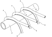
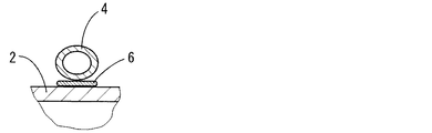
具体的には、図1に示されるように、管内が水通路とされる直管状の大径の水管2に対して、その外周面上に、管内が冷媒通路とされる、水管2よりも細径の冷媒管4の1本乃至複数本、ここでは3本が螺旋状に巻き付けられる際に、3条の帯状のハンダ板材6が、それら冷媒管4と共に供給され、水管2の外周面上においてハンダ板材6と冷媒管4とが積層されてなる形態において、巻き付けられることとなる。即ち、図2に拡大して示される如く、水管2の外周面上に帯状のハンダ板材6が配置され、更にハンダ板材6の上に、冷媒管4が配置されてなる重ね合わせ形態において、それら水管2とハンダ板材6と冷媒管4とが組み付けられるのである。
Specifically, as shown in FIG. 1, compared to a
なお、かかる水管2や冷媒管4の材質としては、従来から公知の金属材質が適宜に採用され得るものであるが、一般に、銅又は銅合金材質が有利に用いられ、中でも、水管2は銅製とされる一方、冷媒管4は銅合金製とされることが望ましい。そして、それら水管2や冷媒管4のサイズは、何れも公知の範囲内で選定され、例えば水管2は、9.0〜16.0mmφ程度の外径を有するものとされ、また冷媒管4は、2.0〜5.0mmφ程度の外径を有するものとされる。更に、水管2には、公知の如く、その内面に、各種の加工が施され得るものであって、例えば、多数の溝や凸起が形成されていても、また外周面に螺旋状に設けた溝に対応して螺旋状の凸条が内周面に形成されてなる、所謂スパイラル管とされていても、何等差し支えない。
In addition, as a material of the
一方、ハンダ板材6の材質としては、後述する350℃を越えない温度での加熱条件下において、溶融し得るものであれば、公知の如何なる材質のものをも採用可能であるが、特に、本発明にあっては、重量基準で、Sn:96.5%−Ag:3.5%なる合金組成のハンダ(融点:221℃)が、有利に用いられることとなる。そして、かかるハンダ板材6は、一般に、板幅:2.5〜8.0mm程度、好ましくは3.0〜6.0mm程度、板厚:0.1〜0.5mm程度、好ましくは0.2〜0.3mm程度のサイズにおいて用いられることとなる。けだし、板幅が小さくなり過ぎたり、板厚が薄くなり過ぎたりすると、水管2と冷媒管4の接合を有効に行ない難くなるからであり、また板幅が大きくなり過ぎると、ハンダ材の無駄が生じるようになるからである。更に、板厚が厚くなり過ぎると、水管2と冷媒管4との間に隙間が生じ易くなり、好ましくないのである。
On the other hand, as the material of the
また、そこにおいて、水管2に対する冷媒管4やハンダ板材6の供給には、それぞれが巻回されてなるロールやコイル等を供給源として、それらから、冷媒管4やハンダ板材6を取り出して供給する方式が採用される他、ハンダ板材6においては、図3に示される如く、円形断面形状のハンダ線材8を圧延ロール10、10にて圧延して、扁平化することにより、帯状のハンダ板材6を形成し、これを水管2の外周面上に連続的に供給する手法も、好適に採用されることとなる。こうすることによって、帯状のハンダ板材6が容易に形成され得て、一定量のハンダ供給が容易に実現され得ることとなる。なお、このロール圧延方式を採用すれば、例えば、1.6mmφのハンダ線材をロール圧延することによって、板幅が3〜6mm程度、厚みが0.2〜0.3mm程度となる帯板状のハンダ材が容易に得られるのである。
In addition, the
さらに、かかる水管2の外周面上へのハンダ板材6と冷媒管4との巻付けに際しては、それらハンダ板材6と冷媒管4とを同時に巻き付ける方式が採用される他、ハンダ板材6の巻付けに先立ち、ハンダ板材6上に冷媒管4を引き揃えて重ね合わせ、配置せしめてなる形態において、水管2の外周面上に巻き付けるようにすることも可能であり、また、水管2の外周面上にハンダ板材6を巻き付けた後、かかる巻き付けられたハンダ板材6上に冷媒管4を巻き付けて、それら水管2とハンダ板材6と冷媒管4との組付けを行なうようにすることも可能である。
Further, when the
そして、かくの如くして得られる水管2とハンダ板材6と冷媒管4とからなる組付け体には、ハンダ板材6の溶融のために加熱が実施されることとなるが、その際、結晶粒度が大きくならないようにして、特に冷媒管4の強度低下を効果的に抑制すべく、母材たる水管2や冷媒管4の温度が高くならないように、換言すれば母材温度が350℃を越えないように、加熱が施され、これによって、ハンダ板材6を溶融せしめて、水管2と冷媒管6との接合が行われることとなるのである。なお、そのような加熱操作は、有利には、トーチ等による火炎を用いて局所的に実施され、そしてその火炎によって、ハンダ板材6が溶融せしめられるようにして、水管2と冷媒管4との接合を実現し、更にその後、空気の噴射等による冷却が実施されることとなる。このように、水管2と冷媒管4との接合は、それらの間に介在せしめたハンダ板材6の溶融によって実現されるものであるところから、上記の加熱温度は、低い温度での加熱ではあるものの、ハンダ板材6が溶融する温度以上に加熱する必要があり、特に実用的には、母材温度が250℃以上となるように加熱されることが望ましい。
Then, the assembly composed of the
かくして、ハンダ溶融物の効果的な供給によって、水管2と冷媒管4とは、図4に示される如く、ハンダ6’にて確実に且つ安定的に接合せしめられることとなるのであるが、その際、母材の温度が高温とならないようにして接合が行なわれることによって、母材、特に冷媒管4の強度低下を効果的に抑制することが出来ることに加えて、結晶粒度の肥大化も抑制乃至は阻止することが出来るところから、その腐食防止も効果的に図ることが出来ることとなるのである。
Thus, due to the effective supply of the solder melt, the
しかも、水管2と冷媒管4とが、それらの間にハンダ板材6を挟んだ形態において、かかるハンダ板材6を溶融せしめて接合されることとなるところから、それら水管2と冷媒管4との接合部位には、常にハンダ溶融物が存在することとなり、これによって、水管2と冷媒管4との接合が有効に行なわれ得ることとなるのであり、またそれによって、ハンダの溶け落ちが生じたり、ハンダ溶融物が水管2と冷媒管4との接合界面に供給されなくなって、それら水管2と冷媒管4との間に接合不良を惹起せしめる等の問題の発生も、効果的に解消せしめられ得ることとなるのである。
In addition, in a form in which the
また、それら水管2と冷媒管4とのハンダ接合を採用する場合において、従来の一方法の如く、ハンダをディッピングにて付与して、それら水管2と冷媒管4との接合を行なうと、それらの管表面に必要以上にハンダが乗ってしまい、無駄が生ずるようになるのであるが、本発明の如く、水管2と冷媒管4との間にハンダ板材6を配置せしめて、接合が行なわれるようにすることによって、必要最小限度のハンダ量において冷媒管4の接合が可能となるのであって、これにより、熱交換器の製造コストを低減することも可能となる。
Further, when adopting solder joining between the
ところで、上述の如き冷媒管4の巻き工程とハンダ付け工程とを含む、熱交換器の製造方法の一例が、図5に示されている。
By the way, an example of the manufacturing method of a heat exchanger including the winding process and soldering process of the
そこにおいて、(a)は、図1に示される如くして、ハンダ板材6と冷媒管4とが水管2の外周面に巻き付けられてなる組付け体12を示している。そのような組付け体12は、例えば、水管2をその軸心回りに回転せしめ且つその軸心方向に移動させつつ、ハンダ板材6と冷媒管4とが重なり合うように、水管2の外周面に供給することによって、製造することが出来る。
1A shows an
そして、そのような組付け体12は、(b)に示される如く、その軸心回りに回転せしめられつつ軸心方向に移動させられてなる状態下において、トーチ14にて発生する火炎16に曝されることにより局所的に加熱され、これによって、水管2の外周面と冷媒管4との間に挟持されているハンダ板材6が溶融せしめられるようになっており、更にその溶融したハンダ溶融物にて、それら水管2と冷媒管4とが接合されるようになっているのである。このように、トーチ火炎16にて加熱するようにした場合においても、水管2と冷媒管4とが接合温度に達する前に、融点の低いハンダ板材6が先に溶融して溶け落ちてしまうということも、より効果的に阻止され得ることとなるのである。更にその後、火炎16にて生じるハンダ板材6の溶融物にて接合された水管2と冷媒管4の接合体20には、それらの周りに配置された空気吹出しノズル18から噴出せしめられる空気によって冷却されることにより、それら水管2や冷媒管4を迅速に冷却せしめて、ハンダ溶融物を凝固させる。
Then, as shown in (b), such an
次いで、かくの如くして得られる水管2と冷媒管4との接合体20には、従来と同様にして曲げ加工が施されて、(c)に示されるように、渦巻き形状乃至はトラック形状の形態において、熱交換器22として、用いられることとなるのであるが、そのような曲げ加工においても、上述の如き巻付けの工程やハンダ付けの工程を経た接合体20にあっては、水管2と冷媒管4との間に確実に溶融ハンダが供給されて、充分な面積において、また隙間等の欠陥も発生させることなく、確実に接合せしめられているところから、角部の如き大きな曲げ加工部位においても、水管2と冷媒管4との間に隙間が惹起される等の問題の発生が、有利に阻止され得ているのである。
Next, the joined
以上、本発明の代表的な実施形態ついて詳述してきたが、それは、あくまでも例示に過ぎないものであって、本発明は、そのような実施形態に係る具体的な記述によって、何等限定的に解釈されるものではないことが、理解されるべきである。 The exemplary embodiments of the present invention have been described in detail above, but this is merely an example, and the present invention is not limited in any way by the specific description according to such embodiments. It should be understood that it is not interpreted.
例えば、例示の実施形態においては、給湯用熱交換器を対象として説明してきたが、それに限定されるものではなく、公知の各種の熱交換器に適用することが可能であることは、言うまでもないところである。 For example, in the illustrated embodiment, the heat exchanger for hot water supply has been described as an object. However, the present invention is not limited thereto, and it is needless to say that the present invention can be applied to various known heat exchangers. By the way.
また、目的とする熱交換器のタイプに応じて、前記した曲げ工程を採用することなく、水管2を直管形態のままで用いる等、公知の各種の構造乃至は形態を採用することが可能である。
Also, according to the type of heat exchanger to be used, it is possible to adopt various known structures or forms such as using the
さらに、例示の実施形態においては、水管2の外周面に冷媒管4を巻き付けて接合するタイプの熱交換器が、その対象とされているのであるが、水管2の外周面に対して、冷媒管4を、水管2の軸心と平行に沿わせるように配置して、接合するタイプの熱交換器にも、本発明は、同様に適用可能である。
Furthermore, in the illustrated embodiment, the heat exchanger of the type in which the
その他、一々列挙はしないが、本発明は、当業者の知識に基づいて、種々なる変更、修正、改良等を加えた態様において実施され得るものであり、そして、そのような実施態様が、本発明の趣旨を逸脱しない限りにおいて、何れも、本発明の範疇に属するものであることは、言うまでもないところである。 In addition, although not listed one by one, the present invention can be implemented in a mode with various changes, modifications, improvements, and the like based on the knowledge of those skilled in the art. It goes without saying that any one of them falls within the scope of the present invention without departing from the spirit of the invention.
2 水管 4 冷媒管
6 ハンダ板材 6’ ハンダ
8 ハンダ線材 10 圧延ロール
12 組付け体 14 トーチ
16 火炎 18 空気吹出しノズル
20 接合体 22 熱交換器2
Claims (9)
かかる水管と冷媒管との接合に、2.5〜8.0mmの板幅と0.1〜0.5mmの板厚を有する帯状のハンダ板材を用いて、該ハンダ板材が該水管の外周面上に配置され、更に該ハンダ板材の上に該冷媒管が配置されるように、それら水管とハンダ板材と冷媒管とを重ね合わせ形態において組み付けた後、350℃を越えない温度に加熱することにより、該ハンダ板材を溶融せしめて、それら水管と冷媒管との接合を行なうことを特徴とする熱交換器の製造方法。 The inside of the pipe is a water passage, the outer diameter is 9.0 to 16.0 mm, and the outer diameter of the water pipe is joined to the outer peripheral surface of the water pipe to be a refrigerant passage. When manufacturing a heat exchanger composed of one or a plurality of refrigerant tubes,
For joining the water pipe and the refrigerant pipe, a strip-shaped solder plate material having a plate width of 2.5 to 8.0 mm and a plate thickness of 0.1 to 0.5 mm is used, and the solder plate material is an outer peripheral surface of the water tube. The water pipe, the solder plate material, and the refrigerant pipe are assembled in a superposed form so that the refrigerant pipe is arranged on the solder plate material, and then heated to a temperature not exceeding 350 ° C. Thus, the solder plate material is melted and the water pipe and the refrigerant pipe are joined together.
9. The method according to claim 1, further comprising a step of bending a joined body obtained by joining the water pipe and the refrigerant pipe into a spiral shape or a track shape. 10. Method of manufacturing a heat exchanger.
Priority Applications (1)
| Application Number | Priority Date | Filing Date | Title |
|---|---|---|---|
| JP2013550150A JP5903444B2 (en) | 2011-12-22 | 2012-08-20 | Heat exchanger manufacturing method and heat exchanger obtained thereby |
Applications Claiming Priority (4)
| Application Number | Priority Date | Filing Date | Title |
|---|---|---|---|
| JP2011281540 | 2011-12-22 | ||
| JP2011281540 | 2011-12-22 | ||
| JP2013550150A JP5903444B2 (en) | 2011-12-22 | 2012-08-20 | Heat exchanger manufacturing method and heat exchanger obtained thereby |
| PCT/JP2012/070990 WO2013094249A1 (en) | 2011-12-22 | 2012-08-20 | Method for manufacturing heat exchanger and heat exchanger obtained by same |
Publications (2)
| Publication Number | Publication Date |
|---|---|
| JPWO2013094249A1 JPWO2013094249A1 (en) | 2015-04-27 |
| JP5903444B2 true JP5903444B2 (en) | 2016-04-13 |
Family
ID=48668156
Family Applications (1)
| Application Number | Title | Priority Date | Filing Date |
|---|---|---|---|
| JP2013550150A Active JP5903444B2 (en) | 2011-12-22 | 2012-08-20 | Heat exchanger manufacturing method and heat exchanger obtained thereby |
Country Status (4)
| Country | Link |
|---|---|
| EP (1) | EP2796236A4 (en) |
| JP (1) | JP5903444B2 (en) |
| CN (1) | CN104010755A (en) |
| WO (1) | WO2013094249A1 (en) |
Families Citing this family (3)
| Publication number | Priority date | Publication date | Assignee | Title |
|---|---|---|---|---|
| CN103522470A (en) * | 2013-10-31 | 2014-01-22 | 苏州市高精勤精密模具有限公司 | Metal bent fluid flat pipeline for industrial cooling |
| CN106642983A (en) * | 2015-10-30 | 2017-05-10 | 杭州三花家电热管理系统有限公司 | Cooling device and control method thereof |
| DE102019101740B4 (en) | 2019-01-24 | 2021-08-05 | Dr. Ing. H.C. F. Porsche Aktiengesellschaft | Method for manufacturing a microchannel bundle heat exchanger |
Family Cites Families (14)
| Publication number | Priority date | Publication date | Assignee | Title |
|---|---|---|---|---|
| JPS6188996A (en) * | 1984-10-05 | 1986-05-07 | Furukawa Electric Co Ltd:The | Sn-sb alloy solder |
| JP2000332041A (en) * | 1999-05-17 | 2000-11-30 | Ricoh Microelectronics Co Ltd | Mounting substrate manufacturing method and manufacturing equipment |
| JP2002252294A (en) * | 2001-02-22 | 2002-09-06 | Sumitomo Metal Electronics Devices Inc | Solder and semiconductor package using it |
| JP2002364989A (en) * | 2001-06-07 | 2002-12-18 | Daikin Ind Ltd | Method for manufacturing heat exchanger |
| JP4121986B2 (en) * | 2004-07-21 | 2008-07-23 | アルプス電気株式会社 | Antenna device |
| JP4449856B2 (en) * | 2004-08-26 | 2010-04-14 | 三菱電機株式会社 | Twisted tube heat exchanger |
| JP3953074B2 (en) * | 2005-05-16 | 2007-08-01 | ダイキン工業株式会社 | Heat exchanger |
| JP2008180460A (en) * | 2007-01-25 | 2008-08-07 | Daikin Ind Ltd | Method for producing heat exchanger, and heat exchange produced by the method |
| JP4819765B2 (en) * | 2007-08-22 | 2011-11-24 | 三菱電機株式会社 | Method for manufacturing twisted tube heat exchanger |
| JP4713562B2 (en) * | 2007-11-21 | 2011-06-29 | 三菱電機株式会社 | Heat exchanger and heat pump water heater using the same |
| CN101245973B (en) * | 2008-03-21 | 2010-08-18 | 北京美联桥科技发展有限公司 | Double-U type loop heat exchanger |
| JP2011092983A (en) | 2009-10-30 | 2011-05-12 | Toshiba Carrier Corp | Method for producing heat exchanger, heat exchanger and heat pump type molten metal supplying device |
| WO2011125324A1 (en) * | 2010-04-02 | 2011-10-13 | ダイキン工業株式会社 | Apparatus and method for manufacturing heat exchanger |
| JP2011212742A (en) * | 2010-04-02 | 2011-10-27 | Daikin Industries Ltd | Joining apparatus, and method for manufacturing heat exchanger |
-
2012
- 2012-08-20 EP EP12860916.1A patent/EP2796236A4/en not_active Withdrawn
- 2012-08-20 WO PCT/JP2012/070990 patent/WO2013094249A1/en unknown
- 2012-08-20 CN CN201280063753.6A patent/CN104010755A/en active Pending
- 2012-08-20 JP JP2013550150A patent/JP5903444B2/en active Active
Also Published As
| Publication number | Publication date |
|---|---|
| WO2013094249A1 (en) | 2013-06-27 |
| EP2796236A4 (en) | 2015-10-14 |
| JPWO2013094249A1 (en) | 2015-04-27 |
| EP2796236A1 (en) | 2014-10-29 |
| CN104010755A (en) | 2014-08-27 |
Similar Documents
| Publication | Publication Date | Title |
|---|---|---|
| KR101446695B1 (en) | Heat exchanger for refrigeration cycle and manufacturing method for same | |
| JP2015090266A (en) | Heat exchanger and method of producing the same | |
| BR102013021664A2 (en) | PROCESS FOR PRODUCTION OF CLIFFED CLIPPING TUBE AND CLADED TUBE | |
| JP5903444B2 (en) | Heat exchanger manufacturing method and heat exchanger obtained thereby | |
| WO2017018438A1 (en) | Heat exchanger and method for producing same | |
| US20160209127A1 (en) | Heat Transfer Tube, Heat Transfer Tube Manufacturing Method, and Heat Exchanger | |
| US20180214963A1 (en) | Heat exchanger and method for producing same | |
| CN105171259A (en) | Composite pipe and manufacturing method and application thereof | |
| KR100867143B1 (en) | Pipe with stainless steel for heat exchange process of the same | |
| JP2010065916A (en) | Heat exchanger and method of manufacturing the same | |
| GB2486788A (en) | A heat exchanger, a tube for a heat exchanger, a method of making a tube for a heat exchanger and a method of making a heat exchanger | |
| JPH05115934A (en) | Manufacture of flattened tube for heat exchanger | |
| JP5896995B2 (en) | Method for manufacturing a clad tube and clad tube | |
| JP2012000645A (en) | Joining method of aluminum pipe and copper pipe, joining structure and heat exchanger having the joining structure | |
| JPS60145268A (en) | Production of heat exchanging element | |
| JP2013533117A5 (en) | ||
| KR100574337B1 (en) | Manufacturing Method of Cooling Fin for Heat-Exchanger | |
| CN110564946B (en) | Non-cooling induction heater for postweld heat treatment of small-diameter pipe welding joint and manufacturing method thereof | |
| CN106563931A (en) | Production method of collecting pipe | |
| JP2008180460A (en) | Method for producing heat exchanger, and heat exchange produced by the method | |
| JP5633206B2 (en) | Joining method and joining structure of aluminum tube and copper tube, and heat exchanger having this joining structure | |
| US20120211208A1 (en) | Brazing joints | |
| WO2017168747A1 (en) | Pipe and heat exchanger provided with said pipe | |
| JP2005262277A (en) | Heat exchange pipe and method for manufacturing the same | |
| JP2011202672A (en) | Joint body and heat exchanger with the same |
Legal Events
| Date | Code | Title | Description |
|---|---|---|---|
| A131 | Notification of reasons for refusal |
Free format text: JAPANESE INTERMEDIATE CODE: A131 Effective date: 20150602 |
|
| A521 | Request for written amendment filed |
Free format text: JAPANESE INTERMEDIATE CODE: A523 Effective date: 20150803 |
|
| A131 | Notification of reasons for refusal |
Free format text: JAPANESE INTERMEDIATE CODE: A131 Effective date: 20151215 |
|
| A521 | Request for written amendment filed |
Free format text: JAPANESE INTERMEDIATE CODE: A523 Effective date: 20160212 |
|
| TRDD | Decision of grant or rejection written | ||
| A01 | Written decision to grant a patent or to grant a registration (utility model) |
Free format text: JAPANESE INTERMEDIATE CODE: A01 Effective date: 20160308 |
|
| A61 | First payment of annual fees (during grant procedure) |
Free format text: JAPANESE INTERMEDIATE CODE: A61 Effective date: 20160314 |
|
| R150 | Certificate of patent or registration of utility model |
Ref document number: 5903444 Country of ref document: JP Free format text: JAPANESE INTERMEDIATE CODE: R150 |
|
| R250 | Receipt of annual fees |
Free format text: JAPANESE INTERMEDIATE CODE: R250 |
|
| R250 | Receipt of annual fees |
Free format text: JAPANESE INTERMEDIATE CODE: R250 |
|
| R250 | Receipt of annual fees |
Free format text: JAPANESE INTERMEDIATE CODE: R250 |
|
| R250 | Receipt of annual fees |
Free format text: JAPANESE INTERMEDIATE CODE: R250 |
|
| R250 | Receipt of annual fees |
Free format text: JAPANESE INTERMEDIATE CODE: R250 |