JP5901330B2 - Vacuum cleaner and vacuum cleaner attachment set - Google Patents
Vacuum cleaner and vacuum cleaner attachment set Download PDFInfo
- Publication number
- JP5901330B2 JP5901330B2 JP2012027197A JP2012027197A JP5901330B2 JP 5901330 B2 JP5901330 B2 JP 5901330B2 JP 2012027197 A JP2012027197 A JP 2012027197A JP 2012027197 A JP2012027197 A JP 2012027197A JP 5901330 B2 JP5901330 B2 JP 5901330B2
- Authority
- JP
- Japan
- Prior art keywords
- pipe
- proximal
- joint pipe
- joint
- opening
- Prior art date
- Legal status (The legal status is an assumption and is not a legal conclusion. Google has not performed a legal analysis and makes no representation as to the accuracy of the status listed.)
- Active
Links
- 238000009429 electrical wiring Methods 0.000 claims description 21
- 230000007246 mechanism Effects 0.000 claims description 11
- 230000002093 peripheral effect Effects 0.000 claims description 10
- 238000005520 cutting process Methods 0.000 claims description 5
- 238000003780 insertion Methods 0.000 description 22
- 230000037431 insertion Effects 0.000 description 22
- 238000012856 packing Methods 0.000 description 14
- 238000013461 design Methods 0.000 description 9
- 210000000078 claw Anatomy 0.000 description 6
- 238000010586 diagram Methods 0.000 description 6
- 239000000428 dust Substances 0.000 description 5
- 230000000694 effects Effects 0.000 description 3
- 238000000034 method Methods 0.000 description 3
- 238000003825 pressing Methods 0.000 description 3
- 230000015572 biosynthetic process Effects 0.000 description 2
- 230000001771 impaired effect Effects 0.000 description 2
- 239000000463 material Substances 0.000 description 2
- 238000011179 visual inspection Methods 0.000 description 2
- 238000004140 cleaning Methods 0.000 description 1
- 230000008878 coupling Effects 0.000 description 1
- 238000010168 coupling process Methods 0.000 description 1
- 238000005859 coupling reaction Methods 0.000 description 1
- 230000005611 electricity Effects 0.000 description 1
- 210000002478 hand joint Anatomy 0.000 description 1
- 238000012986 modification Methods 0.000 description 1
- 230000004048 modification Effects 0.000 description 1
- 238000003860 storage Methods 0.000 description 1
Images


Description
この発明は、隙間ノズルを備えた掃除機および掃除機のアタッチメント一式に関するものである。 The present invention relates to a vacuum cleaner provided with a gap nozzle and a set of attachments of the vacuum cleaner.
従来、一般的な掃除機の隙間ノズルは未使用時にパイプ部分や本体部分に保持あるいは格納されており、当該隙間ノズルを使用する際には、隙間ノズルの取り出し、手元側にあるパイプと床ブラシ側にあるパイプとを取り外し、取り出した隙間ノズルを手元側にあるパイプに取り付けるといった手順を踏む必要があり、使用時の煩わしさがあった。 Conventionally, a gap nozzle of a general vacuum cleaner is held or stored in a pipe part or a main body part when not in use, and when using the gap nozzle, the gap nozzle is taken out and the pipe and floor brush on the hand side are removed. It is necessary to take the procedure of removing the pipe on the side and attaching the taken-out gap nozzle to the pipe on the hand side, which is troublesome during use.
この使用時の煩わしさを解消する技術が種々提案されている。例えば特許文献1には、掃除機の手元操作部を有するグリップの先端、あるいはグリップに接続される延長用パイプの先端に、一体型の隙間ノズルを設ける構成が開示されている。また、特許文献2には、吸込みホースに連通する本体部の先端部に、弾性部材を設けた隙間用吸込口を一体的に設ける構成が開示されている。特許文献1および特許文献2の構成により、隙間ノズルの保管場所を不要とし、隙間ノズルの取り付け操作を不要とすることができる。
Various techniques for eliminating the troublesomeness in use have been proposed. For example, Patent Document 1 discloses a configuration in which an integrated gap nozzle is provided at the tip of a grip having a hand operating portion of a vacuum cleaner or the tip of an extension pipe connected to the grip. Further,
しかしながら、上述した特許文献1および特許文献2に開示された技術では、隙間ノズルの先端部分がパイプ内に収納されるため、隙間ノズルの先端部分に吸引物が溜まってしまう、また隙間ノズルに凹凸部が形成され、床や壁を傷つけてしまうという課題があった。さらに、パイプ同士の位置決めや固定のために、固定用のヘコ形状や回転防止のための凹凸を設ける必要があり、パイプ外観の意匠的美観を損ねるという課題があった。
However, in the techniques disclosed in Patent Document 1 and
この発明は、上記のような課題を解決するためになされたもので、隙間ノズルの先端部分をパイプ内に収納することなく、且つパイプ同士の位置決め部材や固定部材を不要とする掃除機および掃除機のアタッチメント一式を提供することを目的とする。 The present invention has been made to solve the above-described problems. A vacuum cleaner and a cleaning device that do not need to store the tip portion of the gap nozzle in the pipe and do not require a positioning member or a fixing member between the pipes. The purpose is to provide a complete set of machine attachments.
この発明に係る掃除機は、手元側パイプの継手パイプ側接続端部に、手元側パイプを斜めに切断して得られる略楕円形状の開口部を備えた手元側ノズルを設け、継手パイプの手元側パイプ側接続端部は、手元側ノズルの開口部に当接する略楕円形状の当接部と、手元側ノズルの内周面に嵌合する接続部とを備え、手元側ノズルを継手パイプに接続した場合に、手元側ノズルの開口部が継手パイプに対して外側に位置し、手元側ノズルの開口部の外周形状と継手パイプの手元側パイプ側接続部の当接部の外周形状とが一致するものである。 The vacuum cleaner according to the present invention, the joint pipe side connection end portion of the proximal side pipe, the proximal nozzle provided with an opening substantially elliptical shape obtained by cutting the proximal pipe diagonally, hand joint pipe The side pipe side connection end includes a substantially elliptical contact portion that contacts the opening of the proximal nozzle and a connection portion that fits to the inner peripheral surface of the proximal nozzle, and the proximal nozzle serves as a joint pipe. When connected, the opening of the proximal nozzle is located outside the joint pipe, and the outer peripheral shape of the opening of the proximal nozzle and the outer peripheral shape of the contact portion of the proximal pipe side connecting part of the joint pipe are It matches .
この発明によれば、ノズルの先端部分に吸引物が溜まるのを防止することができる。また、位置決め部材や固定部材を設けることなくパイプ同士を接続することができ、パイプ外観の意匠的美観を保つことができる。 According to this invention, it is possible to prevent the suctioned matter from being collected at the tip portion of the nozzle. Moreover, pipes can be connected without providing a positioning member or a fixing member, and the design appearance of the pipe appearance can be maintained.
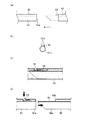
本発明の掃除機および掃除機のアタッチメント一式の説明を行う前に、上述した従来の掃除機の構成および課題について図11および図12を参照しながら説明する。
まず図11(a)は上記特許文献に記載された掃除機の接続部分を示す斜視図であり、図11(b),(c)はこの従来の掃除機の不具合を示す説明図である。
図11(a)に示すように、従来の掃除機では、隙間ノズル90aが手元側パイプ90側に形成され、当該隙間ノズル90aが継手パイプ91の開口部91a内に挿入され、開口部91aが隙間ノズル90aの当接部90bに当接することにより、手元側パイプ90と継手パイプ91が接続される。
Prior to the description of the vacuum cleaner and the attachment of the vacuum cleaner according to the present invention, the configuration and problems of the conventional vacuum cleaner described above will be described with reference to FIGS. 11 and 12.
First, FIG. 11A is a perspective view showing a connecting portion of the vacuum cleaner described in the above-mentioned patent document, and FIGS. 11B and 11C are explanatory views showing the problems of this conventional vacuum cleaner.
As shown in FIG. 11 (a), in the conventional cleaner, the
隙間ノズル90aを継手パイプ91内に挿入することから、隙間ノズル90aに突部である当接部90bの形成が必要となり、隙間ノズル90aの外観の美観を損ねる、さらに隙間ノズル90aを狭い空間に挿入した際に突部である段差部分が家具や壁を傷付けるという不具合が生じていた。また、継手パイプ91の開口部91aおよび隙間ノズル90aの当接部90bは、隙間ノズル90aを継手パイプ91内に挿入する際の挿入方向に対して垂直方向の面上に形成されることから、隙間ノズル90aがどの方向に回転している場合でも、継手パイプ91内に挿入できてしまう。さらに挿入後には、隙間ノズル90aおよび継手パイプ91が共に回転してしまう。そのため、隙間ノズル90aと継手パイプ91とを正しい位置で接続させるために、位置決め部材、固定用のヘコ形状、および回転防止部材を設ける必要があり、隙間ノズル90aの外観の意匠的美観を損ねるという不具合があった。
Since the
また、図11(a)に示すように、各パイプの接続時の密着性を向上させるために、隙間ノズル90aにパッキン90cを配置する場合があり、パッキン90cが露出し、隙間ノズル90a使用時に当該パッキン90cの紛失や破損につながる危険性があった。
In addition, as shown in FIG. 11A, in order to improve the adhesion at the time of connecting each pipe, a
さらに、図11(b)に示すように、隙間ノズル90aが継手パイプ91内に位置した状態で吸引を行うと図11(c)に示すように、隙間ノズル90aの先端に塵などの吸引物が付着するという不具合が生じていた。
Further, as shown in FIG. 11B, when suction is performed in a state where the
また、図12(a)および図12(b)に示すように、手元側パイプ90および継手パイプ91に電気配線部92が配置される場合があり、手元側パイプ90と継手パイプ91では通電ピン93と通電穴92aにより接続される。しかし、上述したように手元側パイプ90と継手パイプ91はどのような位置関係でも接続可能であることから、接続には位置決めが必要となり、ユーザは目視しながら通電ピン93を通電穴92aに挿入する必要があった。そのため、掃除機の手元操作部(不図示)が上部に位置する場合に、通電ピン93および通電穴92aが、手元側パイプ90および継手パイプ91の上部に位置するように配置される必要があり、手元側パイプ90および隙間ノズル90aの上部の形状に制約が生じていた。さらに、通電ピン93は、先当たりしない側のパイプに配置するため、隙間ノズル90aの上方に配置する必要があり、隙間ノズル90aを狭い空間に挿入した場合などに通電ピン93が家具などにぶつかって破損するという不具合があった。
In addition, as shown in FIGS. 12A and 12B, an
また、図12(c)および図12(d)に示すように、手元側パイプ90と継手パイプ91間に取り外しスイッチを設ける場合があり、この取り外しスイッチの操作にもユーザの目視が必要であり、且つ隙間ノズル90aを継手パイプ91内に挿入するため、継手パイプ91の上部にボタン94を配置し、隙間ノズル90aの上部に係合穴95を形成する必要があった。取り外し操作を行う場合、継手パイプ91のボタン94を押しながら、手元側パイプ90を引き抜くあるいは差し込む必要があり、操作が煩わしいという不具合があった。
Also, as shown in FIGS. 12 (c) and 12 (d), a removal switch may be provided between the
次に、上述した不具合を解消するための本発明の構成について説明を行う。
実施の形態1.
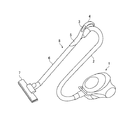
図1は、実施の形態1による掃除機全体の構成を示す斜視図である。
実施の形態1による掃除機は、電動送風機や集塵室などを搭載した掃除機本体1と、当該掃除機本体1に接続されるホース2と、ホース2の他端部に手元操作部3が設けられた手元ハンドル4および手元側パイプ5が接続され、手元側パイプ5には、継手パイプ6および床ブラシ7が順に着脱可能に接続されている。なお、以下で説明する本願発明の特徴的構成を有する手元操作部3から床ブラシ(吸口体)7までが掃除機アタッチメント一式8を構成する。
Next, the configuration of the present invention for solving the above-described problems will be described.
Embodiment 1 FIG.
FIG. 1 is a perspective view showing a configuration of the entire cleaner according to the first embodiment.
The vacuum cleaner according to Embodiment 1 includes a vacuum cleaner main body 1 equipped with an electric blower, a dust collection chamber, and the like, a
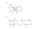
図2は、実施の形態1による掃除機の接続部を拡大して示した斜視図であり、図2(a)は手元側パイプと継手パイプを分解した状態を示し、図2(b)は手元側パイプと継手パイプを接続した状態を示す。
手元側パイプ5と継手パイプ6は、同一の外形形状を有し、接続機構を介して互いに着脱可能に構成されている。接続機構は、手元側パイプ5の先端部分に設けた手元側パイプ開口部5aと、継手パイプ6の先端部分に設けた継手パイプ当接部6aおよび手元側接続部6bとで構成される。手元側パイプ開口部5aと、継手パイプ当接部6aは、手元側パイプ5と継手パイプ6の挿脱方向(以下、挿脱方向Aと称する)に対して所定角度αの傾きを有した面上に形成される。なお、手元ハンドル4が上方に位置する場合に、所定角度αを有した面は、図2(a)の紙面に対して奥行き方向に直交する。
FIG. 2 is an enlarged perspective view showing a connection portion of the vacuum cleaner according to Embodiment 1, FIG. 2 (a) shows a state in which the hand side pipe and the joint pipe are disassembled, and FIG. The state where the hand side pipe and the joint pipe are connected is shown.
The
手元側パイプ5と継手パイプ6を接続する場合には、図2(b)に示すように手元側接続部6bを手元側パイプ5内に挿入し、手元側パイプ開口部5aが継手パイプ当接部6aに当接するまで入れ込む。手元側接続部6bに、例えばパッキン6cを配置することにより、パッキン6cが手元側パイプ5の内側壁面に密着し、吸気能力を向上させることができる。
When connecting the
次に、狭い空間に挿入可能な隙間ノズルとして機能する手元側パイプ5の詳細について説明する。
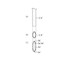
図3は、実施の形態1による掃除機の手元側パイプの形状を示す図である。図3(a)は手元側パイプを図2(b)で示した矢印B方向から見た図、図3(b)は手元側パイプの垂直断面図、図3(c)は手元側パイプ開口部の正面視を示す図である。なお、図3(b)の垂直断面図は、図3(a)に示した手元側パイプを紙面に対して奥行き方向に直交する面で切断した場合の断面図である。
図3(b)に示すように、手元側パイプの垂直断面図は正円あるいは正円に近い形状をしている。一方、手元側パイプ開口部5aは挿脱方向Aに対して所定角度αの傾きを有した面上に形成されていることから、図3(c)に示すように手元側パイプ開口部5aを正面から見た形状、すなわち所定角度αの直角方向から見た形状は楕円形状となる。これにより、手元側パイプ開口部5a近傍を隙間ノズル(以下、手元側隙間ノズル9と称する)として用いた際の吸気面積を確保することができる。
Next, details of the
FIG. 3 is a diagram showing the shape of the hand side pipe of the vacuum cleaner according to the first embodiment. 3A is a view of the hand side pipe seen from the direction of arrow B shown in FIG. 2B, FIG. 3B is a vertical sectional view of the hand side pipe, and FIG. 3C is a hand side pipe opening. It is a figure which shows the front view of a part. Note that the vertical cross-sectional view of FIG. 3B is a cross-sectional view of the proximal side pipe shown in FIG. 3A cut along a plane perpendicular to the depth direction with respect to the paper surface.
As shown in FIG. 3B, the vertical cross-sectional view of the proximal side pipe has a perfect circle or a shape close to a perfect circle. On the other hand, since the proximal
また、手元側パイプ開口部5aの楕円形状は、手元ハンドル4が上方に位置する場合(図2(a)参照)に、手元側パイプ開口部5aの上端部5bと下端部5cを結んだ線上に楕円の長径5dが位置する。これにより、手元側パイプ開口部5aの上端部5bが下端部5cに対して突出し、上端部5b近傍に細い先端部分が形成される。手元側パイプ開口部5a近傍を手元側隙間ノズル9として用いた場合に、当該上端部5b近傍の細い先端部分が狭い空間に入り込む。
なお、図3では手元側パイプ5を例に説明を行ったが、継手パイプ6の垂直断面図も同様に正円あるいは正円に近い形状を有し、継手パイプ当接部6aを正面から見た形状は楕円形状であり、上端部と下端部を結んだ線上に楕円の長径が位置する。
The elliptical shape of the hand
In FIG. 3, the
このように、手元側パイプ5の先端部分に、挿脱方向Aに対して所定角度αの傾きを有する面上に楕円形状の手元側パイプ開口部5aを設けることにより、別部材のアタッチメントなどを装着することなく、手元側パイプ開口部5a近傍を狭い空間にも挿入可能な手元側隙間ノズル9として機能させることができる。
In this manner, by providing the elliptical proximal-
また、手元側パイプ開口部5aおよび継手パイプ当接部6aの形成面が、挿脱方向Aに対して所定角度α傾斜しているため、手元側パイプ開口部5aと継手パイプ当接部6aとの当接位置が限定される。すなわち、手元側パイプ5と継手パイプ6の接続位置が限定される。これにより、位置決め部材を設けることなく、ユーザは容易に正しい接続位置を認識することができる。
Further, since the formation surface of the proximal
さらに、手元側パイプ開口部5aおよび継手パイプ当接部6aが挿脱方向Aに対してそれぞれ傾きを有していることから、手元側パイプ5と継手パイプ6が接続状態である場合に、手元側パイプ5が継手パイプ6に対して、または継手パイプ6が手元側パイプ5に対して回転するのを防止することができる。これにより、手元側パイプ5または手元側接続部6bに、接続を固定するためのヘコ形状や、回転を防止するための凹凸部を設ける必要がなく、手元側隙間ノズル9の外観の意匠的美観を損なうことがない。
Furthermore, since the proximal
次に、手元側パイプ5と継手パイプ6を接続した際に、手元側隙間ノズル9が継手パイプ6の外側に位置する点について説明する。
継手パイプ6にパッキン6cを配置した手元側接続部6bを形成し、当該手元側接続部6bを手元側パイプ内5に挿入することから、手元側隙間ノズル9および手元側パイプ開口部5aが、手元側接続部6bの外側に位置する。これにより、以下のような効果が発生する。
Next, the point that the hand
Since the proximal
図4は、実施の形態1による掃除機の手元側隙間ノズルを適用した場合の吸引物の付着を示す説明図である。図4(a)は手元側パイプと継手パイプを接続した状態を示し、図4(b)は手元側パイプを継手パイプから引き抜いた状態を示している。
図4(a)および図4(b)に示すように、手元側隙間ノズル9が手元側接続部6bの外側に位置し、且つ継手パイプ6に設けた手元側接続部6bが塵などの吸引物の吸引方向Cに向けて開口しているため、手元側パイプ開口部5aおよび手元側接続部6bの開口部に塵などが付着するのを防止することができる。
FIG. 4 is an explanatory diagram showing the attachment of aspirated material when the hand side clearance nozzle of the vacuum cleaner according to Embodiment 1 is applied. FIG. 4A shows a state where the proximal side pipe and the joint pipe are connected, and FIG. 4B shows a state where the proximal side pipe is pulled out from the joint pipe.
As shown in FIGS. 4A and 4B, the
また、図2および図4に示すように、手元側隙間ノズル9が手元側接続部6bの外側に位置することから、手元側隙間ノズル9の外周面に凹凸が生じない。そのため、手元側隙間ノズル9を狭い空間に挿入した場合にも家具や壁などを傷付けることがない。また、手元側隙間ノズル9の外観の意匠的美観を向上させることができる。さらに、パッキン6cが手元側接続部6b上に配置されることから、手元側隙間ノズル9にパッキンを装着する必要がなく、パッキンの紛失および損傷を防止することができる。
Further, as shown in FIGS. 2 and 4, since the
以上のように、この実施の形態1によれば、手元側パイプ5および継手パイプ6の挿脱方向Aに対して所定角度αの傾きを有する面上に開口部である手元側パイプ開口部5aを形成するように構成したので、手元操作部が上方に位置する場合(図2(a)参照)に、当該手元側パイプ開口部の上端部近傍に細い先端部分を有し、且つ吸気面積を確保した手元側隙間ノズルを設けることができる。これにより、手元側パイプに別部材のアタッチメントなどを装着することなく、手元側パイプを引き抜くのみで手元側パイプ開口部近傍を隙間ノズルとして利用することができる。
As described above, according to the first embodiment, the proximal
また、この実施の形態1によれば、手元側パイプ開口部5aおよび継手パイプ当接部6aの形成面が、挿脱方向Aに対して所定角度α傾斜するように構成したので、継手パイプに対する手元側パイプの挿入位置を容易に認識することができる。手元側パイプに対して継手パイプが、および継手パイプが手元側パイプに対して回転するのを防止することができる。これにより、手元側パイプおよび継手パイプに位置決め部材や接続を固定する部材を設ける必要がなくなり、手元側隙間ノズル、手元側パイプおよび継手パイプの外観の意匠的美観を維持することができる。
Moreover, according to this Embodiment 1, since it formed so that the formation surface of the near side
また、この実施の形態1によれば、継手パイプ6に手元側接続部6bを形成し、当該手元側接続部6bを手元側パイプ5内に収納するように構成したので、手元側隙間ノズル9および手元側パイプ開口部5aを手元側接続部6bの外側に配置させることができる。これにより、手元側パイプ開口部5aおよび手元側接続部6bの開口部に塵などが付着するのを防止することができる。また、凹凸のない手元側隙間ノズル9を形成することができ、家具や壁の損傷を防止することができる。さらに、手元側隙間ノズル9にパッキンを配置する必要がなく、パッキンの紛失および損傷を防止することができる。
Further, according to the first embodiment, since the proximal
なお、上述した実施の形態1で示した、挿脱方向Aに対する所定角度αは、手元側パイプ5の手元側パイプ開口部5a近傍が手元側隙間ノズル9として機能する角度であれば適宜変更可能である。
The predetermined angle α with respect to the insertion / removal direction A shown in the first embodiment can be changed as appropriate as long as the vicinity of the proximal side pipe opening 5a of the
実施の形態2.
上述した実施の形態1では、手元側パイプおよび継手パイプを正円あるいは正円に近い形状で構成する例を示したが、この実施の形態2では、手元側パイプおよび継手パイプの垂直断面形状を楕円とする構成について示す。
図5は、実施の形態2による掃除機の手元側パイプおよび継手パイプの形状を示す図である。図5(a)は手元側パイプおよび継手パイプを図2(b)で示した矢印B方向から見た図、図5(b)は手元側パイプおよび継手パイプの垂直断面図、図5(c)は手元側パイプ開口部および継手パイプ当接部の正面視を示す図である。なお、図5(b)の垂直断面図は、図5(a)に示した手元側パイプを紙面に対して奥行き方向に直交する面で切断した場合の断面図である。
In Embodiment 1 described above, an example in which the proximal side pipe and the joint pipe are configured in a perfect circle or a shape close to a perfect circle has been shown. However, in
FIG. 5 is a diagram illustrating the shapes of the proximal side pipe and the joint pipe of the vacuum cleaner according to the second embodiment. 5A is a view of the proximal side pipe and the joint pipe as viewed from the direction of the arrow B shown in FIG. 2B, FIG. 5B is a vertical sectional view of the proximal side pipe and the joint pipe, and FIG. ) Is a diagram showing a front view of the proximal side pipe opening and the joint pipe contact portion. The vertical cross-sectional view of FIG. 5B is a cross-sectional view of the proximal side pipe shown in FIG. 5A cut along a plane perpendicular to the depth direction with respect to the paper surface.
なお、この実施の形態2の手元側パイプ5´および継手パイプ6´において、手元側パイプ開口部5a´および継手パイプ当接部6a´が、挿脱方向Aに対して所定角度αの傾きを有した面上に形成される点、および継手パイプ6´には、手元側パイプ5´に挿入可能な手元側接続部6b´が形成されている点は、実施の形態1と同一であるため、説明を省略する。
In the
図5では、実施の形態1で示した手元側パイプ開口5aと同一の吸気面積を有する手元側パイプ5を示している。同一の吸気面積を有し、且つ手元側パイプ5´の形状を楕円としていることから、図5(a)の正面視では、実施の形態1の図3(a)で示した正面視よりもパイプ幅が細くなっている。図5(b)の垂直断面図では楕円形状を有している。 手元側パイプ5´および継手パイプ6´の楕円の上端部と下端部の位置が一致しない場合には、手元側パイプ5´を継手パイプ6´内に挿入することができない。このように、手元側パイプ5´と継手パイプ6´の垂直断面形状を楕円形状とすることにより、接続位置が限定され、位置決め部材が不要となる。また、当該楕円形状により、手元側パイプ5´と継手パイプ6´とが互いに回転するのを防止することができる。
FIG. 5 shows the
また、手元側パイプ開口部5a´は挿脱方向Aに対して所定角度αの傾きを有して形成されていることから、図5(c)に示すように手元側パイプ開口部5a´を正面から見た形状は実施の形態1の図5(b)と比較して楕円の長径がより長い楕円形状となる。これにより、手元側パイプ開口部5a´近傍を手元側隙間ノズル9として用いた際の吸気面積を確保することができる。さらに、手元ハンドル4が上方に位置する場合(図2(a)参照)、手元側隙間ノズル9の上端部近傍の先端部分が実施の形態1よりも細い形状となり、より細い隙間にも挿入可能となる。
Further, since the proximal
手元側パイプ開口部5a´の形状を、図5(c)を参照しながらより具体的に説明すると、手元ハンドル4が上方に位置する場合(図2(a)参照)に、手元側パイプ開口部5a´の上端部5b´と下端部5c´を結んだ線上に楕円の長径5d´が位置する。実施の形態1と比較して楕円の長径5d´がより長く、短径が短いことから、手元側パイプ開口部5a´の上端部5b´により細い先端部分を形成される。手元側パイプ開口部5a´近傍を手元側隙間ノズル9として用いた場合に、先端部分をより狭い空間に挿入させることができる。
なお、図5(c)の説明では、手元側パイプ開口部5a´を例に説明を行ったが、継手パイプ当接部6a´を正面から見た形状は楕円形状であり、上端部と下端部を結んだ線上に長径が位置する。
The shape of the hand
In the description of FIG. 5C, the proximal
このように、手元側パイプ5´および継手パイプ6´の垂直断面形状を楕円とすることにより、手元側パイプ5´と継手パイプ6´との接続位置が限定されると共に、手元側パイプ5´と継手パイプ6´とが互いに回転するのを防止することができる。さらに手元側パイプ開口部5aの上端部5b´により細い先端部分が形成され、より狭い空間に挿入可能な手元側隙間ノズル9を形成することができる。
また、実施の形態1と同様に、手元側パイプ開口部5a´および継手パイプ当接部6a´が、挿脱方向Aに対して所定角度αの傾きを有した面上に形成され、継手パイプ6´には、手元側パイプ5´に挿入可能な手元側接続部6b´が形成されることから、実施の形態1と同様の効果を有する。
Thus, by making the vertical cross-sectional shapes of the
Similarly to the first embodiment, the proximal
なお、図5では、手元側パイプ5´および継手パイプ6´の垂直断面形状を楕円状とするように構成したが、楕円状に限定されるものではなく、種々構成可能である。図6は、実施の形態2の掃除機の手元側パイプおよび継手パイプのその他の垂直断面形状を示す図である。なお、以下の説明では、手元側パイプ5´および継手パイプ6´に共通する説明であるため、手元側パイプ5´および継手パイプ6´を各パイプと称して説明する。また、図6(a)から図6(f)は、手元ハンドル4が上方に位置する場合(図2(a)参照)の垂直断面形状を示している。
In FIG. 5, the vertical cross-sectional shapes of the
図6(a)は、各パイプの上方を細く、下方を太くしたしずく形状の垂直断面形状を示している。
図6(b)は、各パイプの4隅の角に丸みを設けた矩形形状の垂直断面形状を示している。なお、手元側隙間ノズル9を狭い隙間に挿入した場合に、家具や壁などを傷付けてしまうのを防止する目的で、各パイプの4隅の角に丸みを設ける構成を示しているが、図6(c)のように丸みを設けない矩形形状としてもよい。
FIG. 6A shows a vertical cross-sectional shape of a drop shape in which the upper part of each pipe is thin and the lower part is thick.
FIG. 6B shows a rectangular vertical cross-sectional shape in which the four corners of each pipe are rounded. In addition, in order to prevent damage to furniture or walls when the
図6(d)は、矩形形状の各パイプの長手方向の2辺を短手方向に膨らませた樽形状の垂直断面形状を示している。
図6(e)は、各パイプの上端部に頂点が位置する三角形状の垂直断面形状を示している。
図6(f)は、各パイプの半円形状と矩形形状とを組み合わせた垂直断面形状を示している。この場合、各パイプの上部に半円形状を位置させることにより、家具や壁を傷付けるのを防止する。
FIG. 6D shows a barrel-shaped vertical cross-sectional shape in which two long sides of each rectangular pipe are expanded in the short direction.
FIG. 6E shows a triangular vertical cross-sectional shape with the apex located at the upper end of each pipe.
FIG. 6 (f) shows a vertical cross-sectional shape combining the semicircular shape and the rectangular shape of each pipe. In this case, the furniture and the wall are prevented from being damaged by placing a semicircular shape on the upper part of each pipe.
図6(a)から図6(f)に示した形状とすることにより、手元側隙間ノズルの先端部分の細さを維持し、且つ十分な空気面積を確保することができる。また、正円以外の形状とすることにより、手元側パイプ5´と継手パイプ6´の接続位置を限定することができる。
上述した図6(a)から図6(f)以外にも、手元側隙間ノズル9の先端部分が狭い隙間に挿入可能であり、且つ十分な吸気面積を確保可能であり、手元側パイプ5´と継手パイプ6´の接続位置を限定可能な形状であれば、手元側パイプ5´と継手パイプ6´の垂直断面形状は種々構成可能である。
By adopting the shape shown in FIGS. 6A to 6F, it is possible to maintain the thinness of the tip portion of the proximal gap nozzle and to secure a sufficient air area. Moreover, the connection position of the
6A to 6F described above, the distal end portion of the
以上のように、この実施の形態2によれば、手元側パイプ5´および継手パイプ6´の、垂直断面形状を楕円形状に構成したので、手元側パイプ5´と継手パイプ6´の接続位置を容易に認識することができる。さらに、手元側パイプ5´と継手パイプ6´とが互いに回転するのを防止することができる。
As described above, according to the second embodiment, the vertical cross-sectional shapes of the
また、この実施の形態2によれば、手元側パイプ5´および継手パイプ6´の、垂直断面形状を楕円形状とし、さらに手元側パイプ5´および継手パイプ6´の挿脱方向Aに対して所定角度αの傾きを有する面上に手元側パイプ開口部5a´を設けるように構成したので、手元側パイプ開口部の楕円の長径をより長く設定することができ、手元側隙間ノズルの先端部分をより細く構成することができる。
Further, according to the second embodiment, the vertical cross-sectional shapes of the
実施の形態3.
この実施の形態3では、上述した実施の形態1および実施の形態2の構成に加えて、掃除機本体1の床ブラシ7に搭載された電動機に電気を供給するための電気配線が手元側パイプ5,5´と継手パイプ6,6´の外側に配置されている場合について説明する。
まず、電気配線について図1を参照しながら説明する。通常掃除機は、掃除機本体1のモータ(不図示)と手元操作部3が電気的に接続され、手元操作部3の操作によりモータの駆動が電気的に制御される。これに加えて床ブラシ7の動作も電気的に制御する場合には、さらに手元操作部3と床ブラシ7とを電気的に接続する必要がある。その際、手元操作部3および床ブラシ7間の電気配線が、手元側パイプ5,5´と継手パイプ6,6´の外側あるいは内側に配置される。
Embodiment 3 FIG.
In the third embodiment, in addition to the configurations of the first and second embodiments described above, the electrical wiring for supplying electricity to the electric motor mounted on the
First, electrical wiring will be described with reference to FIG. In the normal vacuum cleaner, a motor (not shown) of the vacuum cleaner main body 1 is electrically connected to the hand operation unit 3, and the drive of the motor is electrically controlled by the operation of the hand operation unit 3. In addition to this, when the operation of the
図7は、実施の形態3による掃除機において外側に電気配線を配置した手元側パイプおよび継手パイプの構成を示す図である。
図7(a)は電気配線を配置した手元側パイプおよび継手パイプの側面図、図7(b)は電気配線を配置した実施の形態1の手元側パイプの手元側開口部側正面図、および図7(c)は電気配線を配置した実施の形態2の手元側パイプの手元側開口部側正面図である。
なお図7は、手元ハンドル4が上方に位置する場合(図2(a)参照)における、手元側パイプ5,5´および継手パイプ6,6´の構成を示している。
FIG. 7 is a diagram showing a configuration of a proximal side pipe and a joint pipe in which electric wiring is arranged outside in the vacuum cleaner according to the third embodiment.
FIG. 7A is a side view of the proximal side pipe and the joint pipe in which the electrical wiring is arranged, FIG. 7B is a front view of the proximal side opening side of the proximal side pipe in Embodiment 1 in which the electrical wiring is disposed, and FIG. 7C is a front view of the proximal side opening of the proximal side pipe of the second embodiment in which the electrical wiring is arranged.
FIG. 7 shows the configuration of the
図7(a)に示すように、内部に電気配線を行った電気配線部11,11´が、手元側パイプ5,5´と継手パイプ6,6´の下方外側に、各パイプの長手方向に沿って配置される。さらに図7(a)から図7(c)に示すように、継手パイプ当接部6a,6a´下方の電気配線部11,11´に、継手パイプ6,6´の長手方向に突出した通電ピン12が形成され、当該通電ピン12が差し込まれる通電穴11a,11a´が手元側パイプ開口部5a,5a´下方の電気配線部11,11´に形成される。
As shown in FIG. 7 (a), the
実施の形態1および実施の形態2で述べたように、手元側パイプ開口部5a,5a´および継手パイプ当接部6a,6a´が、楕円形状を有することにより、手元側パイプ5,5´と継手パイプ6,6´の接続位置が限定される。手元側パイプ5,5´と継手パイプ6,6´の接続に位置決めが不要であることから、この実施の形態3においても通電ピン12を通電穴11a,11a´に差し込む際に、ユーザの目視を必要としない。これにより、手元ハンドル4が上方に位置する状態で、電気配線部11,11´を手元側パイプ5,5´および継手パイプ6,6´の下方に配置することができる。
As described in the first and second embodiments, the proximal
さらに、電気配線部11,11´を手元側パイプ5,5´および継手パイプ6,6´の下方に配置することにより、先当たりしない位置に配置する通電ピン12を継手パイプ当接部6a,6a´側に形成することができる。通電ピン12が手元側隙間ノズル9として狭い空間に挿入する手元側パイプ開口部5a,5a´側に形成されないことから、通電ピン12が家具や壁にぶつかり、破損するのを防止することができる。
Further, by arranging the
なお、図7では、電気配線部11,11´を手元側パイプ5,5´および継手パイプ6,6´外部の下方に配置する構成を示したが、電気配線部11,11´を手元側パイプ5,5´および継手パイプ6,6´内部の下方に配置してもよい。電気配線部11,11´を手元側パイプ5,5´および継手パイプ6,6´内部に配置すると、各パイプに内側形状に制約が生じるが、手元側隙間ノズル9として機能する手元側パイプ開口部5a,5a´の上部の形状に制約が生じないため、実施の形態1および実施の形態2と同様の効果が得られる。
FIG. 7 shows a configuration in which the
以上のように、この実施の形態3によれば、挿脱方向Aに対して所定角度αの傾きを有した面上に楕円形状に形成された手元側パイプ開口部5a,5a´および継手パイプ当接部6a,6a´を備えた手元側パイプ5,5´および継手パイプ6,6´に電気配線部11,11´を設けるように構成したので、通電ピンと通電穴の接続に位置決めが不要となり、当該通電ピンと通電穴を備えた電気配線部を手元側パイプおよび継手パイプの下方に配置することができる。これにより、手元側パイプおよび継手パイプの外観の意匠的美観を損なうことなく電気配線を行うことができる。また、手元側隙間ノズルとして機能する手元側パイプ開口部5aの上部の形状が制約されるのを防ぐことができる。
As described above, according to the third embodiment, the proximal
また、この実施の形態3によれば、電気配線部を手元側パイプおよび継手パイプの下方に配置するように構成したので、通電ピンを隙間ノズルとして使用しない継手パイプ当接部6a,6a´下方に配置することができ、通電ピン12の破損を防止し、手元側隙間ノズルの外観の意匠的美観を損なうことがない。
Further, according to the third embodiment, since the electrical wiring portion is arranged below the proximal side pipe and the joint pipe, the joint
実施の形態4.
この実施の形態4では、手元側パイプと継手パイプとを係合あるいは係合を解除するスイッチを備える構成を示す。なお以下では、実施の形態1で示した手元側パイプ5および継手パイプ6を例に説明を行うが、実施の形態2で示した手元側パイプ5´および継手パイプ6´の係合あるいは係合解除にも適用可能である。
図8は、実施の形態4による掃除機の手元側パイプと継手パイプの係合機構を示す断面図である。図8(a)は手元側パイプ5と継手パイプ6の接続状態を示し、図8(b)は手元側パイプ5と継手パイプ6の接続解除状態を示している。なお図8では、手元ハンドル4が上方に位置する場合(図2(a)参照)を示している。
In this
FIG. 8 is a cross-sectional view showing an engagement mechanism between the proximal side pipe and the joint pipe of the cleaner according to the fourth embodiment. FIG. 8A shows a connection state between the
手元側パイプ5と継手パイプ6の係合機構は種々適用可能であるが、図8に示す係合機構は、手元側パイプ5の下方に設けたボタン13、ボタン13の他端部に設けた係合爪13aおよび継手パイプ6の下方に設けた係合爪13aaが係合する凹部14で構成されている。
Although various engagement mechanisms for the
実施の形態1で述べたように、手元側パイプ開口部5aおよび継手パイプ当接部6aが楕円形状を有することにより、手元側パイプ5と継手パイプ6の接続位置が限定される。手元側パイプ5と継手パイプ6の接続に位置決めが不要であることから、この実施の形態4においてもボタンの押圧や各パイプの取り外しあるいは差し込みにユーザの目視を必要としない。これにより、手元ハンドル4が上方に位置する状態で、ボタン13、係合爪13aおよび凹部14aを手元側パイプ5および継手パイプ6の下方に配置することができる。
As described in the first embodiment, when the proximal
ボタン13、係合爪13aおよび凹部14aを手元側パイプ5および継手パイプ6の下方に配置することにより、手元側隙間ノズル9として機能する手元側パイプ開口部5a,5a´の上部の形状に制約が生じない。そのため、継手パイプ6を引き抜くよりもより容易に動作が行える手元側パイプ5の引き抜きにおいて、引き抜く手元側パイプ5側にボタン13を配置することができる。これにより、少なくともボタン13を押圧し(図8(b)の矢印D)、手元側パイプ5を引き抜く(図8(b)の矢印E)動作のみで、手元側パイプ5と継手パイプ6との係合を解除し、取り外すことができる。
By arranging the
以上のように、この実施の形態4によれば、挿脱方向Aに対して所定角度αの傾きを有した面上に楕円形状に形成された手元側パイプ開口部5aおよび継手パイプ当接部6aを備えた手元側パイプ5および継手パイプ6にボタン13、係合爪13aおよび凹部14で構成される係合機構を配置するように構成したので、ボタン操作、パイプの取り外しあるいは差し込みに位決めが不要となり、係合機構を手元側パイプおよび継手パイプの下方に配置することができる。これにより、手元側パイプおよび継手パイプの外観の意匠的美観を損なうことなくパイプの係合機構を設けることができる。また、手元側隙間ノズルとして機能する手元側パイプ開口部5aの上部の形状が制約されるのを防ぐことができる。
As described above, according to the fourth embodiment, the proximal
また、この実施の形態4によれば、係合機構を手元側パイプおよび継手パイプの下方に配置するように構成したので、手元側パイプに押圧するボタンを配置することができ、パイプの取り外し動作を容易にすることができる。 Further, according to the fourth embodiment, since the engagement mechanism is configured to be disposed below the proximal side pipe and the joint pipe, a button for pressing the proximal side pipe can be disposed, and the pipe removing operation is performed. Can be made easier.
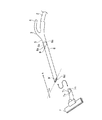
上述した実施の形態1から実施の形態4では、手元側パイプ5に手元側隙間ノズル9を構成する手元側パイプ開口部5aを設ける構成を示したが、図9に示すように、手元側パイプ5に接続された継手パイプ6にさらに第2の継手パイプ10を接続し、継手パイプ開口部6dを各パイプの挿脱方向Aに対して所定角度αの傾きを有して形成し、当該継手パイプ開口部6d近傍を継手側隙間ノズル9´として構成してもよい。この場合、第2の継手パイプ10には、第2の継手パイプ当接部10aおよび継手パイプ側接続部10bを設け、さらに継手パイプ側接続部10bにパッキン10cを配置してもよい。
In Embodiments 1 to 4 described above, the configuration in which the
また、図10に示すように、第2の継手パイプ10を設けない場合にも、継手パイプ6と床ブラシ7との接続部分における継手パイプ開口部6dを継手パイプの挿脱方向Aに対して所定角度αの傾きを有して形成してもよい。これにより、継手パイプ開口部6d近傍を継手側隙間ノズル9´として構成することができる。この場合、床ブラシ7には、当接部7aおよび継手パイプ側接続部7bを設け、さらに継手パイプ側接続部7bにパッキン7cを配置してもよい。
In addition, as shown in FIG. 10, even when the second
なお、本願発明はその発明の範囲内において、各実施の形態の自由な組み合わせ、あるいは各実施の形態の任意の構成要素の変形、もしくは各実施の形態において任意の構成要素の省略が可能である。 In the present invention, within the scope of the invention, any combination of the embodiments, or any modification of any component in each embodiment, or omission of any component in each embodiment is possible. .
1 掃除機本体、2 ホース、3 手元操作部、4 手元ハンドル、5,5´ 手元側パイプ、5a,5a´ 手元側パイプ開口部、5b,5b´ 上端部、5c,5c´ 下端部、5d,5d´ 楕円の長径、6,6´ 継手パイプ、6a,6a´ 継手パイプ当接部、6b,6b´ 手元側接続部、6c,7c,10c パッキン、6d 継手パイプ開口部、7 床ブラシ、7a 当接部、7b 継手パイプ側接続部、8 アタッチメント一式、9 手元側隙間ノズル、9´ 継手側隙間ノズル、10 第2の継手パイプ、10a 第2の継手パイプ当接部、10b 継手パイプ側接続部、11、11´ 電気配線部、11a,11a´ 通電穴、12 通電ピン、13 ボタン、13a 係合爪、14 凹部。 1 Vacuum cleaner body, 2 hose, 3 hand operation section, 4 hand handle, 5, 5 'hand side pipe, 5a, 5a' hand side pipe opening, 5b, 5b 'upper end, 5c, 5c' lower end, 5d , 5d 'ellipse long diameter, 6, 6' joint pipe, 6a, 6a 'joint pipe contact portion, 6b, 6b' proximal side connection portion, 6c, 7c, 10c packing, 6d joint pipe opening, 7 floor brush, 7a contact part, 7b joint pipe side connection part, 8 attachment set, 9 hand side clearance nozzle, 9 'joint side clearance nozzle, 10 second joint pipe, 10a second joint pipe contact part, 10b joint pipe side Connection part, 11, 11 'Electrical wiring part, 11a, 11a' Current supply hole, 12 Current supply pin, 13 button, 13a Engagement claw, 14 Recessed part.
Claims (14)
前記手元側パイプの前記継手パイプ側接続端部に、前記手元側パイプを斜めに切断して得られる略楕円形状の開口部を備えた手元側ノズルを設け、
前記継手パイプの前記手元側パイプ側接続端部は、前記手元側ノズルの開口部に当接する略楕円形状の当接部と、前記手元側ノズルの内周面に嵌合する接続部とを備え、
前記手元側ノズルを前記継手パイプに接続した場合に、前記手元側ノズルの前記開口部が前記継手パイプに対して外側に位置し、前記手元側ノズルの開口部の外周形状と前記継手パイプの前記手元側パイプ側接続部の当接部の外周形状とが一致することを特徴とする掃除機。 In a vacuum cleaner comprising a main body of the vacuum cleaner, a hand side pipe, a joint pipe detachably attached to the hand side pipe, and a suction body connected to the joint pipe,
Provided on the joint pipe side connection end of the proximal side pipe is a proximal side nozzle provided with a substantially elliptical opening obtained by obliquely cutting the proximal side pipe,
The proximal-side pipe-side connection end of the joint pipe includes a substantially elliptical contact portion that contacts the opening of the proximal-side nozzle, and a connection portion that fits to the inner peripheral surface of the proximal-side nozzle. ,
When the proximal nozzle is connected to the joint pipe, the opening of the proximal nozzle is positioned outside the joint pipe, the outer peripheral shape of the opening of the proximal nozzle and the joint pipe The vacuum cleaner characterized by the outer peripheral shape of the contact part of a hand side pipe side connection part agree | coinciding .
前記手元側ノズルの開口部の上端部が下端部に対して前記継手パイプ側に位置し、且つ前記開口部の上端部と下端部とを結ぶ線上に前記略楕円形状の長径が位置することを特徴とする請求項1記載の掃除機。 When a hand handle provided in the vicinity of a hand operation unit for driving the electric vacuum cleaner body is located above,
The upper end of the opening of the proximal nozzle is positioned on the joint pipe side with respect to the lower end, and the substantially elliptical long diameter is positioned on a line connecting the upper end and the lower end of the opening. The vacuum cleaner according to claim 1.
前記継手側ノズルを前記吸口体の接続部に接続した場合に、前記継手側ノズルの前記開口部が前記吸口体の接続部に対して外側に位置することを特徴とする請求項1から請求項4のうちのいずれか1項記載の掃除機。 A joint side nozzle provided with a substantially elliptical opening obtained by obliquely cutting the joint pipe is provided at the mouth end side connection end of the joint pipe,
The said opening part of the said joint side nozzle is located outside with respect to the connection part of the said suction body, when the said joint side nozzle is connected to the connection part of the said suction body. The vacuum cleaner of any one of 4 .
前記手元操作部と前記吸口体とを電気的に接続する電気配線部を、前記手元側パイプおよび前記継手パイプの下方に配置したことを特徴とする請求項2記載の掃除機。 When the opening of the mouthpiece is opposed to the surface to be cleaned and the hand handle provided in the vicinity of the hand operating part is located above,
The vacuum cleaner according to claim 2, wherein an electrical wiring portion that electrically connects the hand operating portion and the suction body is disposed below the hand side pipe and the joint pipe.
前記手元側パイプと前記継手パイプとの接続を固定する係止機構を、前記手元側パイプおよび前記継手パイプの下方に配置したことを特徴とする請求項2記載の掃除機。 When the opening of the mouthpiece is opposed to the surface to be cleaned and the hand handle provided in the vicinity of the hand operating part is located above,
The vacuum cleaner according to claim 2, wherein a locking mechanism for fixing a connection between the proximal side pipe and the joint pipe is disposed below the proximal side pipe and the joint pipe.
前記手元側パイプの前記継手パイプ側接続端部に、前記手元側パイプを斜めに切断して得られる略楕円形状の開口部を備えた手元側ノズルを設け、
前記継手パイプの前記手元側パイプ側接続端部は、前記手元側ノズルの開口部に当接する略楕円形状の当接部と、前記手元側ノズルの内周面に嵌合する接続部とを備え、
前記手元側ノズルを前記継手パイプに接続した場合に、前記手元側ノズルの前記開口部が前記継手パイプに対して外側に位置し、前記手元側ノズルの開口部の外周形状と前記継手パイプの前記手元側パイプ側接続部の当接部の外周形状とが一致することを特徴とする掃除機のアタッチメント一式。 A hand operating part that receives an operation input, a hand side pipe integrally formed with the hand operating part, a joint pipe detachably attached to the hand side pipe, and a suction body connected to the joint pipe In the complete vacuum cleaner attachment set,
Provided on the joint pipe side connection end of the proximal side pipe is a proximal side nozzle provided with a substantially elliptical opening obtained by obliquely cutting the proximal side pipe,
The proximal-side pipe-side connection end of the joint pipe includes a substantially elliptical contact portion that contacts the opening of the proximal-side nozzle, and a connection portion that fits to the inner peripheral surface of the proximal-side nozzle. ,
When the proximal nozzle is connected to the joint pipe, the opening of the proximal nozzle is positioned outside the joint pipe, the outer peripheral shape of the opening of the proximal nozzle and the joint pipe Attachment set of the vacuum cleaner characterized by the outer peripheral shape of the contact part of the hand side pipe side connection part being in agreement .
前記手元側ノズルの開口部の上端部が下端部に対して前記継手パイプ側に位置し、且つ前記開口部の上端部と下端部とを結ぶ線上に前記略楕円形状の長径が位置することを特徴とする請求項10記載の掃除機のアタッチメント一式。 When a hand handle provided in the vicinity of the hand operation unit is positioned above,
The upper end of the opening of the proximal nozzle is positioned on the joint pipe side with respect to the lower end, and the substantially elliptical long diameter is positioned on a line connecting the upper end and the lower end of the opening. The attachment set of the vacuum cleaner of Claim 10 characterized by the above-mentioned.
前記継手側ノズルを前記吸口体の接続部に接続した場合に、前記継手側ノズルの前記開口部が前記吸口体の接続部に対して外側に位置することを特徴とする請求項10から請求項13のうちのいずれか1項記載の掃除機のアタッチメント一式。 A joint side nozzle provided with a substantially elliptical opening obtained by obliquely cutting the joint pipe is provided at the mouth end side connection end of the joint pipe,
The said opening part of the said joint side nozzle is located outside with respect to the connection part of the said suction body when the said joint side nozzle is connected to the connection part of the said suction body, The Claim 10 characterized by the above-mentioned. Attachment set of the vacuum cleaner of any one of 13 .
Priority Applications (1)
| Application Number | Priority Date | Filing Date | Title |
|---|---|---|---|
| JP2012027197A JP5901330B2 (en) | 2012-02-10 | 2012-02-10 | Vacuum cleaner and vacuum cleaner attachment set |
Applications Claiming Priority (1)
| Application Number | Priority Date | Filing Date | Title |
|---|---|---|---|
| JP2012027197A JP5901330B2 (en) | 2012-02-10 | 2012-02-10 | Vacuum cleaner and vacuum cleaner attachment set |
Publications (3)
| Publication Number | Publication Date |
|---|---|
| JP2013162882A JP2013162882A (en) | 2013-08-22 |
| JP2013162882A5 JP2013162882A5 (en) | 2014-12-18 |
| JP5901330B2 true JP5901330B2 (en) | 2016-04-06 |
Family
ID=49174669
Family Applications (1)
| Application Number | Title | Priority Date | Filing Date |
|---|---|---|---|
| JP2012027197A Active JP5901330B2 (en) | 2012-02-10 | 2012-02-10 | Vacuum cleaner and vacuum cleaner attachment set |
Country Status (1)
| Country | Link |
|---|---|
| JP (1) | JP5901330B2 (en) |
Cited By (1)
| Publication number | Priority date | Publication date | Assignee | Title |
|---|---|---|---|---|
| US11937761B2 (en) | 2019-09-11 | 2024-03-26 | Dyson Technology Limited | Attachment for a vacuum cleaning appliance |
Families Citing this family (6)
| Publication number | Priority date | Publication date | Assignee | Title |
|---|---|---|---|---|
| JP2018015299A (en) * | 2016-07-28 | 2018-02-01 | シャープ株式会社 | Extension pipe for vacuum cleaner |
| WO2019157168A1 (en) | 2018-02-09 | 2019-08-15 | Sharkninja Operating Llc | Accessories for a surface treatment apparatus |
| GB2589774B (en) | 2018-07-02 | 2022-11-30 | Sharkninja Operating Llc | Vacuum pod configured to couple to one or more accessories |
| US11399675B2 (en) | 2018-07-31 | 2022-08-02 | Sharkninja Operating Llc | Upright surface treatment apparatus having removable pod |
| WO2020051433A1 (en) | 2018-09-07 | 2020-03-12 | Sharkninja Operating Llc | Battery and suction motor assembly for a surface treatment apparatus and a surface treatment apparatus having the same |
| KR200494259Y1 (en) | 2020-04-03 | 2021-09-07 | 이병대 | Pipe for easy to assemble and separation and suction pipe for vacuum cleaner having the same |
Family Cites Families (8)
| Publication number | Priority date | Publication date | Assignee | Title |
|---|---|---|---|---|
| JPS4822669B1 (en) * | 1969-11-05 | 1973-07-07 | ||
| JPS4822669U (en) * | 1971-07-24 | 1973-03-15 | ||
| JPS51111770U (en) * | 1975-03-06 | 1976-09-09 | ||
| JPS5632647U (en) * | 1979-08-21 | 1981-03-31 | ||
| JPS6355958U (en) * | 1986-09-30 | 1988-04-14 | ||
| JPH06311948A (en) * | 1993-04-30 | 1994-11-08 | Mitsubishi Electric Corp | Pipe joint for vacuum cleaner |
| WO2000000075A1 (en) * | 1998-06-30 | 2000-01-06 | Daewoo Electronics Co., Ltd. | Telescopable wand assembly of a vacuum cleaner |
| JP5278855B2 (en) * | 2008-09-01 | 2013-09-04 | 株式会社やまびこ | Pipe connection structure |
-
2012
- 2012-02-10 JP JP2012027197A patent/JP5901330B2/en active Active
Cited By (1)
| Publication number | Priority date | Publication date | Assignee | Title |
|---|---|---|---|---|
| US11937761B2 (en) | 2019-09-11 | 2024-03-26 | Dyson Technology Limited | Attachment for a vacuum cleaning appliance |
Also Published As
| Publication number | Publication date |
|---|---|
| JP2013162882A (en) | 2013-08-22 |
Similar Documents
| Publication | Publication Date | Title |
|---|---|---|
| JP5901330B2 (en) | Vacuum cleaner and vacuum cleaner attachment set | |
| JP4749157B2 (en) | Vacuum cleaner | |
| TWI574660B (en) | Vacuum cleaner nozzle device | |
| JP2007190110A (en) | Dust collecting device | |
| EP2311357A1 (en) | Suction head for a vacuum cleaner | |
| JP2009066333A (en) | Suction device of vacuum cleaner and vacuum cleaner with suction device | |
| JP2011104224A (en) | Suction tool for vacuum cleaner | |
| JP4895287B2 (en) | Air passage body for vacuum cleaner | |
| JP4751944B2 (en) | Vacuum cleaner and its suction tool | |
| JP6334323B2 (en) | Vacuum cleaner and its suction port | |
| JP2018011676A (en) | Vacuum cleaner | |
| JP3128401U (en) | Hose for vacuum cleaner | |
| JP3870795B2 (en) | Electric vacuum cleaner | |
| TWI810343B (en) | Suction appliances and electric vacuum cleaners | |
| JP2005081149A (en) | Vacuum cleaner | |
| JP4241595B2 (en) | Electric vacuum cleaner | |
| JP2017012689A (en) | Suction port body and vacuum cleaner | |
| JP3868990B1 (en) | Cleaning tool and cleaning member | |
| JP2005287659A (en) | Vacuum cleaner | |
| JP5117965B2 (en) | Electric vacuum cleaner | |
| JPH0530688Y2 (en) | ||
| JP2008136582A (en) | Suction tool for gap for vacuum cleaner | |
| JP4713650B2 (en) | Electric vacuum cleaner | |
| JP4399323B2 (en) | Vacuum cleaner and its suction tool | |
| JP2006081721A (en) | Vacuum cleaner |
Legal Events
| Date | Code | Title | Description |
|---|---|---|---|
| A521 | Request for written amendment filed |
Free format text: JAPANESE INTERMEDIATE CODE: A523 Effective date: 20141104 |
|
| A621 | Written request for application examination |
Free format text: JAPANESE INTERMEDIATE CODE: A621 Effective date: 20141104 |
|
| A977 | Report on retrieval |
Free format text: JAPANESE INTERMEDIATE CODE: A971007 Effective date: 20150525 |
|
| A131 | Notification of reasons for refusal |
Free format text: JAPANESE INTERMEDIATE CODE: A131 Effective date: 20150707 |
|
| A521 | Request for written amendment filed |
Free format text: JAPANESE INTERMEDIATE CODE: A523 Effective date: 20150904 |
|
| TRDD | Decision of grant or rejection written | ||
| A01 | Written decision to grant a patent or to grant a registration (utility model) |
Free format text: JAPANESE INTERMEDIATE CODE: A01 Effective date: 20160209 |
|
| A61 | First payment of annual fees (during grant procedure) |
Free format text: JAPANESE INTERMEDIATE CODE: A61 Effective date: 20160308 |
|
| R150 | Certificate of patent or registration of utility model |
Ref document number: 5901330 Country of ref document: JP Free format text: JAPANESE INTERMEDIATE CODE: R150 |
|
| R250 | Receipt of annual fees |
Free format text: JAPANESE INTERMEDIATE CODE: R250 |
|
| R250 | Receipt of annual fees |
Free format text: JAPANESE INTERMEDIATE CODE: R250 |
|
| R250 | Receipt of annual fees |
Free format text: JAPANESE INTERMEDIATE CODE: R250 |
|
| R250 | Receipt of annual fees |
Free format text: JAPANESE INTERMEDIATE CODE: R250 |
|
| R250 | Receipt of annual fees |
Free format text: JAPANESE INTERMEDIATE CODE: R250 |
|
| R250 | Receipt of annual fees |
Free format text: JAPANESE INTERMEDIATE CODE: R250 |