以下、本発明の最良の形態を、図面に基づいて詳細に説明する。ここでは、遊技機としてパチンコ遊技機(以下、単に「パチンコ機」という)を挙げる。
Hereinafter, the best mode of the present invention will be described in detail with reference to the drawings. Here, pachinko gaming machines (hereinafter simply referred to as “pachinko machines”) are listed as gaming machines.
(パチンコ機正面側の構成)
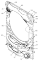
図1はパチンコ機10の正面図、図2はパチンコ機10の斜視図、図3はパチンコ機10の前面枠の斜視図である。図1および図2に示すように、パチンコ機10は、当該パチンコ機10の外殻を形成する外枠11と、この外枠11の一側部に開閉可能に支持された内枠12とを備えている。以下に、外枠11と内枠12との構成を個別に説明する。
(Configuration of front side of pachinko machine)
1 is a front view of the pachinko machine 10, FIG. 2 is a perspective view of the pachinko machine 10, and FIG. 3 is a perspective view of a front frame of the pachinko machine 10. As shown in FIGS. 1 and 2, the pachinko machine 10 includes an outer frame 11 that forms an outer shell of the pachinko machine 10, and an inner frame 12 that is supported on one side of the outer frame 11 so as to be opened and closed. I have. Below, the structure of the outer frame 11 and the inner frame 12 is demonstrated separately.
上記外枠11は、木製の板材により全体として矩形状に構成され、小ネジ等の離脱可能な締結具により各板材が組み付けられている。なお、外枠11は樹脂やアルミニウム等の軽金属により構成されていてもよい。このように構成することにより、パチンコ機の軽量化を図ることができるからである。
The outer frame 11 is formed in a rectangular shape as a whole by a wooden plate material, and each plate material is assembled by a detachable fastener such as a small screw. The outer frame 11 may be made of a light metal such as resin or aluminum. This is because such a configuration can reduce the weight of the pachinko machine.
一方、上記内枠12の開閉軸線はパチンコ機10の正面からみてハンドル(後述する遊技球発射ハンドル18)設置箇所の反対側(図1のパチンコ機10の左側)で上下に延びるように設定されており、この開閉軸線を軸心にして内枠12が前方側に十分に開放できるようになっている。このような構成とするのは、内枠12の開閉軸線がハンドル設置箇所側(図1のパチンコ機10の右側)で上下方向にあるとすると、内枠12を開放する際に遊技球発射ハンドル18の頭部等が隣なりのパチンコ機やカードユニット(球貸しユニット)に干渉することになり、内枠12を十分に開放できないからである。また、内枠12は合成樹脂、具体的にはABS(アクリロニトリル−ブタジエン−スチレン)樹脂から成る。こうすることで、粘性が高く衝撃に強くでき、低コストで製造できるという利点が発揮される。
On the other hand, the opening / closing axis of the inner frame 12 is set so as to extend vertically on the opposite side (left side of the pachinko machine 10 in FIG. 1) from the position where the handle (game ball launching handle 18 described later) is installed as viewed from the front of the pachinko machine 10. The inner frame 12 can be sufficiently opened to the front side with the opening / closing axis as the axis. If the opening / closing axis of the inner frame 12 is in the vertical direction on the handle installation location side (the right side of the pachinko machine 10 in FIG. 1), the game ball launching handle is opened when the inner frame 12 is opened. This is because the 18 heads and the like interfere with adjacent pachinko machines and card units (ball lending units), and the inner frame 12 cannot be fully opened. The inner frame 12 is made of a synthetic resin, specifically, ABS (acrylonitrile-butadiene-styrene) resin. By doing so, the advantages of high viscosity and high impact resistance and low cost production are exhibited.
また、内枠12は、その最下部に下皿ユニット13を有し、内枠12の左側の上下方向の開閉軸線を軸心にして開閉自在に取り付けられた前面枠セット14と、樹脂ベース25(図6参照)と、この樹脂ベース25の後側に取り付けられる後述の遊技盤30とを備えている。これらの各構成を以下に詳細に説明する。
Further, the inner frame 12 has a lower pan unit 13 at the lowermost part thereof, and a front frame set 14 attached to the left and right sides of the inner frame 12 so as to be openable and closable about a vertical opening / closing axis, and a resin base 25. (See FIG. 6) and a game board 30 (to be described later) attached to the rear side of the resin base 25. Each of these configurations will be described in detail below.
上記下皿ユニット13は、前面枠セット14の一部として前面枠ベース部材に固定されている。この下皿ユニット13の前面側には、下皿15と球抜きレバー17と遊技球発射ハンドル18と演出ボタン79が設けられている。球受皿としての下皿15は、下皿ユニット13のほぼ中央部に設けられており、後述の上皿が満タンになった場合等に排出口16より排出される遊技球を停留する役割がある。上記球抜きレバー17は、下皿15内の遊技球を抜くためのものであり、この球抜きレバー17を図1で左側に移動させることにより、下皿15の底面の所定箇所が開口され、下皿15内に停留された遊技球を下皿15の底面の開口部分を通して遊技者の持球貯留箱(ドル箱)に排出することができる。上記遊技球発射ハンドル18は、下皿15よりも右方で手前側に突出するように配設されている。遊技者による遊技球発射ハンドル18の操作に応じて、発射ソレノイドを備えた遊技球発射装置によって遊技球が後述する遊技盤30の方へ打ち込まれるようになっている。前面枠セット14の上部には、スピーカからの音を出力するための音出力口24が設けられている。
The lower plate unit 13 is fixed to the front frame base member as a part of the front frame set 14. On the front side of the lower plate unit 13, a lower plate 15, a ball removal lever 17, a game ball launching handle 18, and an effect button 79 are provided. The lower tray 15 serving as a ball receiving tray is provided at substantially the center of the lower tray unit 13 and plays a role of stopping a game ball discharged from the discharge port 16 when the upper tray described later becomes full. is there. The ball removal lever 17 is for removing a game ball in the lower tray 15, and by moving the ball removal lever 17 to the left in FIG. 1, a predetermined location on the bottom surface of the lower tray 15 is opened. The game ball stopped in the lower plate 15 can be discharged to the player's ball storage box (dollar box) through the opening on the bottom surface of the lower plate 15. The game ball launching handle 18 is disposed so as to protrude to the front side on the right side of the lower plate 15. In accordance with the operation of the game ball launching handle 18 by the player, the game ball is driven toward a game board 30 described later by a game ball launching device having a launch solenoid. A sound output port 24 for outputting sound from a speaker is provided at the upper part of the front frame set 14.
一方、前面枠セット14の下部(上述の下皿15の上方位置)には、遊技球の受皿としての上皿19が前面枠セット14と一体的に設けられている。この上皿19は、遊技球を一旦貯留し、一列に整列させながら遊技球発射装置38の方へ導出するための球受皿である。また、上皿19の左下方には、装飾図柄表示装置42の背景を変える等の操作を遊技者が行なうための演出ボタン79が設けられている。
On the other hand, an upper plate 19 as a receiving tray for game balls is provided integrally with the front frame set 14 at a lower portion of the front frame set 14 (above the lower plate 15 described above). The upper tray 19 is a ball receiving tray for temporarily storing the game balls and guiding them to the game ball launching device 38 while aligning them in a line. In addition, an effect button 79 for the player to perform an operation such as changing the background of the decorative symbol display device 42 is provided at the lower left of the upper plate 19.
加えて、前面枠セット14にはその周囲(例えばコーナー部分)に各種ランプ等の発光手段が設けられている。これら発光手段は、大当たり遊技状態時等における遊技状態の変化に応じて点灯、点滅のように発光態様が変更制御され遊技中の演出効果を高める役割を果たすものである。例えば、窓部101の周縁には、LED等の発光手段を内蔵した環状電飾部102が左右対称に設けられ、大当たり遊技状態時に点灯や点滅を行うことにより、大当たり遊技状態中であることを報知する構成である。
In addition, the front frame set 14 is provided with light emitting means such as various lamps around it (for example, a corner portion). These light emitting means play a role of enhancing the effect of the game during the game by changing and controlling the light emission mode such as lighting and blinking according to the change of the game state in the big hit game state or the like. For example, at the periphery of the window portion 101, an annular illumination portion 102 containing a light emitting means such as an LED is provided symmetrically, and lighting or blinking in the big hit gaming state, it is in a big hit gaming state It is the structure which alert | reports.
また、窓部101の下方には貸球操作部120が配設されており、貸球操作部120には球貸しボタンと、返却ボタンと、度数表示部とが設けられている。パチンコ機10の側方に配置された図示しないカードユニット(球貸しユニット)に紙幣やカード等を投入した状態で貸球操作部120が操作されると、その操作に応じて遊技球の貸出が行われる。球貸しボタンは、カード等(記録媒体)に記録された情報に基づいて貸出球を得るために操作されるものであり、カード等に残額が存在する限りにおいて貸出球が上皿19に供給される。返却ボタンは、カードユニットに挿入されたカード等の返却を求める際に操作される。度数表示部はカード等の残額情報を表示するものである。なお、カードユニットを介さずに球貸し装置部から上皿に遊技球が直接貸し出されるパチンコ機、いわゆる現金機では貸球操作部120が不要となる。故に、貸球操作部120の設置部分に、飾りシール等が付されるようになっている。これにより、カードユニットを用いたパチンコ機と現金機との貸球操作部の共通化が図れる。
In addition, a ball lending operation unit 120 is disposed below the window unit 101, and the ball lending operation unit 120 is provided with a ball lending button, a return button, and a frequency display unit. When the ball lending operation unit 120 is operated with a bill or a card inserted in a card unit (ball lending unit) (not shown) arranged on the side of the pachinko machine 10, a game ball is lent according to the operation. Done. The ball lending button is operated to obtain a lending ball based on information recorded on a card or the like (recording medium), and the lending ball is supplied to the upper plate 19 as long as there is a remaining amount on the card or the like. The The return button is operated when requesting the return of a card or the like inserted into the card unit. The frequency display section displays remaining amount information such as a card. Note that the ball lending operation unit 120 is not required for a pachinko machine in which a game ball is directly rented from the ball lending device unit to the upper plate without using a card unit, that is, a so-called cash machine. Therefore, a decorative seal or the like is attached to the installation portion of the ball rental operation unit 120. Thereby, the common use of the lending operation unit of the pachinko machine using the card unit and the cash machine can be achieved.
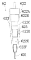
次に、図4を用いて遊技盤30の構成を説明する。図4は遊技盤30の構成を示す正面図である。遊技盤30は、一般入賞口を備える一般入賞装置31、可変入賞装置32、上始動口33aと下始動口33b(作動チャッカ33bで構成)と一対の開閉羽根60とを備える始動入賞装置33、通過口を備える作動入賞装置34(スルーゲートで構成)、主表示ユニット371、装飾図柄表示装置42を備える可変表示装置ユニット35等が設けられている。これらの一般入賞装置31、可変入賞装置32、始動入賞装置33、作動入賞装置34、可変表示装置ユニット35等は、遊技盤30における、ルータ加工によって形成された各貫通穴にそれぞれに配設され、遊技盤30前面側から木ネジ等により取り付けられている。また、下始動口33bの入口には、一対の開閉羽根60が設けられており、遊技球を案内する開放位置と、下始動口33b内に遊技球が入りにくくなる(入らない)閉塞位置を採りうる。開閉羽根60は、遊技盤30の裏面側に配設されたソレノイドSL1によって駆動される。また、上始動口33aの下方には、大入賞口(収容部の入口)61が配置されている。大入賞口61については、後に言及する。大入賞口61内には、入球検出スイッチSW1が設けられている。
Next, the configuration of the game board 30 will be described with reference to FIG. FIG. 4 is a front view showing the configuration of the game board 30. The game board 30 includes a general winning device 31 having a general winning port, a variable winning device 32, a starting winning device 33 including an upper starting port 33a and a lower starting port 33b (configured by an operation chucker 33b), and a pair of opening / closing blades 60, An operation winning device 34 (comprising a through gate) having a passage opening, a main display unit 371, a variable display device unit 35 having a decorative symbol display device 42, and the like are provided. The general winning device 31, the variable winning device 32, the starting winning device 33, the operating winning device 34, the variable display device unit 35 and the like are respectively disposed in the through holes formed by router processing in the game board 30. The game board 30 is attached from the front side with wood screws or the like. In addition, a pair of opening and closing blades 60 are provided at the entrance of the lower start port 33b, and an open position for guiding the game ball and a closed position where the game ball is difficult to enter (does not enter) into the lower start port 33b. Can be taken. The opening / closing blade 60 is driven by a solenoid SL1 disposed on the back side of the game board 30. In addition, a large winning opening (inlet of the accommodating portion) 61 is disposed below the upper start opening 33a. The special winning opening 61 will be described later. In the special winning opening 61, a ball detection switch SW1 is provided.
前述の一般入賞装置31、可変入賞装置32および始動入賞装置33に遊技球が入球し、当該入球が後述する検出スイッチ(入賞口スイッチ、カウントスイッチ、作動口スイッチ等)で検出され、この検出スイッチの出力に基づいて、上皿19(または下皿15)へ所定数の賞品球が払い出される。その他に、遊技盤30にはアウト口36が設けられており、各種入賞装置等に入球しなかった遊技球はこのアウト口36を通って図示しない球排出路の方へと案内されるようになっている。遊技盤30には、遊技球の落下方向を適宜分散、調整等するために多数の釘が植設されているとともに、各種部材(役物)が配設されている。
A game ball enters the above-described general winning device 31, variable winning device 32, and starting winning device 33, and the received ball is detected by a detection switch (a winning port switch, a count switch, an operating port switch, etc.) described later, Based on the output of the detection switch, a predetermined number of prize balls are paid out to the upper plate 19 (or the lower plate 15). In addition, the game board 30 is provided with an out port 36, and game balls that have not entered the various winning devices etc. are guided through the out port 36 to a ball discharge path (not shown). It has become. A number of nails are implanted in the game board 30 in order to appropriately disperse and adjust the falling direction of the game balls, and various members (instruments) are arranged.
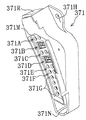
主表示ユニット371は、後述する主制御装置261が直接的に制御する表示装置ユニットであり、図5に示すように、右上の隅部が直角でその対辺が左上から右下へ延びる斜辺となっている、やや上下に長い概略直角三角形の各隅部(角部)が丸く角落ちするとともに、斜辺が遊技領域の右上部に沿って弧状に内側へ湾曲する正面形状を有し、前後に遊技球の直径よりやや大きい程度の厚みを有する立体状の外形を有する部品となっている。主表示ユニット371における右上には、ネジ挿通孔を有するフランジ371Hが背面に沿って形成され、右下の隅部には、前面側から後面壁まで凹入し該後面壁にネジ挿通孔(図示せず)を有する正面視概略U字状のネジ挿通部371Nが形成され、図4に示すように、フランジ371Hおよびネジ挿通部371Nにネジが螺入されて主表示ユニット371が遊技盤30の前面における右上部に固定されている。主表示ユニット371における左上の上面部は左下方へやや下傾するように形成され、その中央部は、図4に示すように、遊技球の最大飛翔部分に対応する外レール52の先端部に近接し、この部位の上に、図5に示すようにゴム板よりなる返しゴム371Rが取り付けられている。この返しゴム371Rにより、所定以上の勢いで発射された遊技球が当たって跳ね返されるようになっている。主表示ユニット371の前面部には、左上端近傍からネジ挿通部371Nに隣接するまで斜辺に沿って弧状に延びる正面形状を有して内奥側へ段状に凹入する表示部371Mが形成されている。
The main display unit 371 is a display device unit that is directly controlled by a main control device 261 described later. As shown in FIG. 5, the upper right corner is a right angle and the opposite side is a hypotenuse extending from the upper left to the lower right. Each corner (corner) of a roughly right triangle that is slightly up and down has rounded corners, and the hypotenuse has a front shape that curves inward along the upper right part of the game area, and plays back and forth. The component has a three-dimensional outer shape having a thickness that is slightly larger than the diameter of the sphere. A flange 371H having a screw insertion hole is formed on the upper right side of the main display unit 371 along the back surface, and a lower right corner is recessed from the front side to the rear wall, and a screw insertion hole (see FIG. A screw insertion portion 371N having a substantially U-shape when viewed from the front is formed, and a screw is screwed into the flange 371H and the screw insertion portion 371N so that the main display unit 371 is connected to the game board 30 as shown in FIG. It is fixed to the upper right part on the front. The upper left upper surface portion of the main display unit 371 is formed so as to be inclined slightly downward to the lower left, and the center portion thereof is located at the tip of the outer rail 52 corresponding to the maximum flying portion of the game ball as shown in FIG. A return rubber 371R made of a rubber plate is attached on this part as shown in FIG. The return rubber 371R hits and rebounds the game ball launched at a predetermined momentum or more. A display portion 371M is formed on the front surface of the main display unit 371. The display portion 371M has a front shape extending in an arc along the oblique side from the vicinity of the upper left end and adjacent to the screw insertion portion 371N, and is stepped into the inner depth. Has been.
上記表示部371Mには、7個の表示装置371A〜371Gが上から弧状に並ぶようにして順に配置されている。表示装置371B(第1特別図柄表示装置)は、上始動口33aへの遊技球の入賞を契機に変動表示される第1特別図柄を表示するものであり、表示装置371D(第2特別図柄表示装置)は、下始動口33bへの遊技球の入賞を契機に変動表示される第2特別図柄を表示するものである。これらの表示装置371B,371Dはそれぞれ、「8」の字状に配列された7個と、隅部にドット状に配列された1個とによる合計8個のLEDのセグメントから構成されている。なお、各特別図柄は、上記表示装置371B,371Dにおいて同時に変動表示されることがなく入賞順に従って順次行われるため、装飾図柄表示装置42においては共通の装飾図柄によって特別図柄に対応する表示が行われるようになっている。表示装置371A(第1特別図柄保留表示装置)は、第1特別図柄の保留数を表示するものであり、表示装置371C(第1特別図柄保留表示装置)は、第2特別図柄の保留数を表示するものである。これらの表示装置371A,371Cはそれぞれ、左右2個のLEDで構成され、左側のLEDのみあるいは両方を点灯又は点滅させることにより最大で4個までの保留数を表示するようになっている。なお、センターフレーム43の下部には、2色の発光が可能な合計4個のランプよりなる保留ランプ800aが装飾図柄表示装置42の下辺に沿って配列されており(図4参照)、この保留ランプ800aによって表示される装飾図柄の保留数は、遊技状態(後述するサポート状態か否か)に応じて、上記表示装置371A,371Cのうち何れかが表示する保留数と対応するようになっている。表示装置371E(普通図柄表示装置)は、作動入賞装置34における通過口への遊技球の入賞を契機に変動表示される普通図柄を表示するものであり、左右2個のLEDで構成され、片側のLEDのみを点灯させることで外れを表示し、両方を点灯させることで当りを表示するようになっている。表示装置371F(普通図柄保留表示装置)は、普通図柄の保留数を表示するものであり、左右2個のLEDで構成され、左側のLEDのみあるいは両方を点灯又は点滅させることにより最大で4個までの保留数を表示するようになっている。表示装置371Gは、遊技状態の種別を表示するものであり、合計8個のLEDで構成されている。これらのLEDがそれぞれ消灯、点灯、点滅の何れかに変化し、全消灯を除く6560通りの組み合わせによって、1.通常遊技状態(大当たり乱数カウンタC1の抽選が低確率であり、サポート状態ではない)、2.時短状態(大当たり乱数カウンタC1の抽選が低確率であり、サポート状態)、3.潜伏高確率状態(大当たり乱数カウンタC1の抽選が高確率であり、サポート状態ではない)、4.高確率状態(大当たり乱数カウンタC1の抽選が高確率であり、サポート状態)、及び5.大当たり状態の何れかを表示するようになっており、大当たり状態を表示するのに際してはその大当たりの最大ラウンド数によって異なる表示が行われる。
In the display unit 371M, seven display devices 371A to 371G are sequentially arranged so as to be arranged in an arc from the top. The display device 371B (first special symbol display device) displays a first special symbol that is variably displayed when a game ball is won in the upper start port 33a. The display device 371D (second special symbol display device) The apparatus) displays a second special symbol that is variably displayed when a game ball is won in the lower start port 33b. Each of these display devices 371B and 371D is composed of a total of eight LED segments, including seven arranged in an “8” shape and one arranged in a dot shape at the corner. Since each special symbol is not sequentially displayed on the display devices 371B and 371D and is sequentially displayed according to a winning order, the decorative symbol display device 42 displays a display corresponding to the special symbol by a common decorative symbol. It has come to be. The display device 371A (first special symbol hold display device) displays the number of holds of the first special symbol, and the display device 371C (first special symbol hold display device) displays the number of holds of the second special symbol. To display. Each of these display devices 371A and 371C is composed of two LEDs on the left and right, and displays the number of holdings of up to four by lighting or blinking only the left LED or both. In the lower part of the center frame 43, a holding lamp 800a composed of a total of four lamps capable of emitting two colors is arranged along the lower side of the decorative symbol display device 42 (see FIG. 4). The number of decoration symbols held displayed by the lamp 800a corresponds to the number of holds displayed by any one of the display devices 371A and 371C depending on the gaming state (whether or not the support state will be described later). Yes. The display device 371E (ordinary symbol display device) displays a normal symbol that is variably displayed in response to the winning of a game ball at the passing port in the operation winning device 34, and is composed of two LEDs on the left and right sides. By turning on only the LED, it is possible to indicate that it is out of place, and by lighting both, it is possible to display a hit. The display device 371F (ordinary symbol hold display device) displays the number of hold of the normal symbol, is composed of two left and right LEDs, and up to four by lighting or blinking only the left LED or both. The number of hold until is displayed. The display device 371G displays the type of gaming state, and is configured by a total of eight LEDs. These LEDs change to any one of the off state, the on state, and the blinking state. 1. Normal gaming state (the lottery of the jackpot random number counter C1 has a low probability and is not in a support state). 2. Short-time state (Lottery of jackpot random number counter C1 is low probability and support state); 3. Hidden high probability state (the lottery of the jackpot random number counter C1 has a high probability and is not in the support state). 4. High probability state (lottery of jackpot random number counter C1 is high probability, support state), and One of the jackpot states is displayed. When the jackpot state is displayed, different display is performed depending on the maximum number of rounds of the jackpot.
上記装飾図柄表示装置42は液晶表示装置として構成されており、後述する表示制御装置により表示内容が制御される。装飾図柄表示装置42には、例えば上、中、及び下の3箇所に識別情報としての図柄(装飾図柄)が表示される。これら図柄がスクロールされて装飾図柄表示装置42に可変表示されるようになっている。なお本形態では、装飾図柄表示装置42(液晶表示装置)は例えば10インチ或いは12インチサイズの大型の液晶ディスプレイを備えている。遊技球が始動入賞装置33を通過した回数は最大4回まで保留され、その保留回数が保留ランプ800aにて点灯表示されるようになっているが、この保留ランプ800aが表示する保留回数は、装飾図柄表示装置42の一部(具体的には右下部)にも表示される。この保留表示は、保留数に対応する数のキャラクタ画像が並列的に表示されるものである。
The decorative design display device 42 is configured as a liquid crystal display device, and display contents are controlled by a display control device to be described later. On the decorative symbol display device 42, for example, symbols (decorative symbols) as identification information are displayed at three locations, upper, middle, and lower. These symbols are scrolled and variably displayed on the decorative symbol display device 42. In this embodiment, the decorative symbol display device 42 (liquid crystal display device) is provided with a large liquid crystal display having a size of 10 inches or 12 inches, for example. The number of times that the game ball has passed through the start winning device 33 is held up to a maximum of 4 times, and the number of times the game ball is lit is displayed on the hold lamp 800a. The hold number displayed by the hold lamp 800a is as follows: It is also displayed on a part of the decorative symbol display device 42 (specifically, the lower right portion). In this hold display, the number of character images corresponding to the number of holds is displayed in parallel.
上記可変入賞装置32は、通常は遊技球が入賞できない又は入賞し難い閉状態になっており、大当たりの際に遊技球が入賞しやすい開状態と通常の閉状態とに繰り返し作動されるようになっているが、その具体的な構成については後述する。簡略に触れれば、特別図柄表示装置が特定の表示態様となった場合(装飾図柄表示装置42の停止後の確定図柄が予め設定した特定の図柄の組み合せとなった場合)に特別遊技状態が発生する。そして、可変入賞装置32が受球状態となり、遊技球の入賞を許す。具体的には、所定時間(例えば30秒)の経過又は所定個数(例えば10個)の入賞を1ラウンドとして、可変入賞装置32の受球状態が所定回数繰り返し開放される。
The variable winning device 32 is normally in a closed state in which a game ball cannot be won or difficult to win, and is repeatedly operated in an open state and a normal closed state in which a game ball is easy to win in a big win. However, the specific configuration will be described later. In short, when the special symbol display device is in a specific display mode (when the confirmed symbol after the decoration symbol display device 42 is stopped is a combination of specific symbols set in advance), the special gaming state is Occur. Then, the variable winning device 32 is in a ball receiving state and allows a game ball to be won. Specifically, the ball receiving state of the variable winning device 32 is repeatedly released a predetermined number of times, with a predetermined time (for example, 30 seconds) or a predetermined number (for example, 10) of winnings taken as one round.
また、図4に示すように、遊技盤30には、遊技球発射装置から発射された遊技球を遊技盤30上部へ案内するためのレールユニット50が取り付けられており、遊技球発射ハンドル18の回動操作に伴い発射された遊技球はレールユニット50を通じて所定の遊技領域に案内されるようになっている。レールユニット50はリング状をなす金属板にて構成されており、内外二重に一体形成された内レール51と外レール52とを有する。内レール51および外レール52の後側端縁(遊技盤30に対向する端縁)には、所定間隔をおいて複数個所に鋲56が設けられており、内レール51および外レール52は該鋲56を打ちつけるようにして遊技盤30に取り付けられている。内レール51は上方の約1/4ほどを除いて略円環状に形成され、一部(主に左側部)が内レール51に向かい合うようにして外レール52が形成されている。かかる場合、内レール51と外レール52とにより誘導レールが構成され、これら各レール51、52が所定間隔を隔てて並行する部分(向かって左側の部分)により球案内通路が形成されている。なお、球案内通路は、遊技盤30との当接面を有した溝状、すなわち手前側を開放した溝状に形成されている。
As shown in FIG. 4, a rail unit 50 for guiding the game ball launched from the game ball launching device to the upper part of the game board 30 is attached to the game board 30. A game ball launched in accordance with the turning operation is guided to a predetermined game area through the rail unit 50. The rail unit 50 is composed of a ring-shaped metal plate, and includes an inner rail 51 and an outer rail 52 that are integrally formed in an inner and outer double. On the rear edge of the inner rail 51 and the outer rail 52 (edge facing the game board 30), a plurality of hooks 56 are provided at predetermined intervals, and the inner rail 51 and the outer rail 52 are The game board 30 is attached to the game board 30 so as to hit the basket 56. The inner rail 51 is formed in a substantially annular shape except for about 1/4 of the upper part, and the outer rail 52 is formed so that a part (mainly the left side) faces the inner rail 51. In such a case, a guide rail is constituted by the inner rail 51 and the outer rail 52, and a spherical guide passage is formed by a portion (the left portion facing) where the rails 51 and 52 are parallel to each other at a predetermined interval. The ball guide passage is formed in a groove shape having a contact surface with the game board 30, that is, a groove shape in which the front side is opened.
内レール51の先端部分(図4の左上部)には戻り球防止部材53が取着されている。これにより、一旦、内レール51および外レール52間の球案内通路から遊技盤30の上部へと案内された遊技球が再度球案内通路内に戻ってしまうといった事態が防止されるようになっている。
A return ball preventing member 53 is attached to the tip of the inner rail 51 (upper left portion in FIG. 4). This prevents a situation in which the game ball once guided from the ball guide path between the inner rail 51 and the outer rail 52 to the upper part of the game board 30 returns to the ball guide path again. Yes.
尚、遊技領域は、レールユニット50の内周部(内外レール)と主表示ユニット371の斜辺とにより略円形状に区画形成されており、特に本形態では、遊技盤30の盤面上に区画される遊技領城が従来よりもはるかに大きく構成されている。
The game area is partitioned into a substantially circular shape by the inner peripheral portion (inner / outer rail) of the rail unit 50 and the oblique side of the main display unit 371. In particular, in this embodiment, the game area is partitioned on the board surface of the game board 30. The game castle is much larger than before.
さらに、遊技盤30の右側縁部には、側端レール50Sが配設されている。側端レール50Sは、内レール51および外レール52とは別体として構成され、また内レール51および外レール52からは間隔を置いて独立に配置されているが、外レール52とおおよそ同一の円周上に位置して遊技領域の右端部を区画しており、即ちレールユニット50の一部(右端部)を構成している。この側端レール50Sの構成および取付構造については後述する。
Further, a side end rail 50 </ b> S is disposed on the right edge of the game board 30. The side end rail 50 </ b> S is configured as a separate body from the inner rail 51 and the outer rail 52, and is disposed independently from the inner rail 51 and the outer rail 52, but is substantially the same as the outer rail 52. It is located on the circumference and demarcates the right end portion of the game area, that is, constitutes a part (right end portion) of the rail unit 50. The configuration and mounting structure of the side end rail 50S will be described later.
(パチンコ機の背面構成)
次に、パチンコ機10の背面の構成を説明する。図6はパチンコ機10の背面の構成を示す分解斜視図である。
(Back view of pachinko machine)
Next, the configuration of the back surface of the pachinko machine 10 will be described. FIG. 6 is an exploded perspective view showing the configuration of the back surface of the pachinko machine 10.
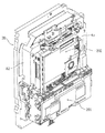
先ず、パチンコ機10の背面構成について全体の概要を説明する。パチンコ機10にはその背面(実際には内枠12および遊技盤30の背面)において、各種制御基板が上下左右に並べられるようにしてまたは前後に重ねられるようにして配置されており、さらに、遊技球を供給するための遊技球供給装置(払出機構)や樹脂製の裏カバー(保護カバー)等が取り付けられている。本形態では、各種制御基板を3つの取付台に分けて搭載して3つの制御基板ユニットを構成し、それら制御基板ユニットを個別に内枠12または遊技盤30の裏面に装着するようにしている。この場合、主制御基板、電源監視基板、これら基板を収容する基板ボックスおよび該基板ボックスを封印する封印ユニットから構成される主制御装置261を一つにユニット化し、表示制御基板、該表示制御基板を収容する基板ボックスおよび装飾図柄表示装置42から構成される表示制御装置45とサブ制御基板および該サブ制御基板を収容する基板ボックスから構成されるサブ制御装置262とを後述する外包部材82に搭載してユニット化し、さらに払出制御基板、該払出制御基板を収容する基板ボックス(払出制御基板ケース)および該基板ボックスを封印する封印ユニットから構成される払出制御装置311と電源基板、発射制御基板およびこれら基板を収容する基板ボックス(電源・発射制御基板ケース203A)から構成される電源・発射制御装置とを1つの取付台に搭載してユニット化している。ここでは便宜上、各ユニットを上記の順に「第1制御基板ユニット201」、「第2制御基板ユニット202」および「第3制御基板ユニット203」と称することとする。
First, an overall outline of the rear configuration of the pachinko machine 10 will be described. On the back surface of the pachinko machine 10 (actually, the back surface of the inner frame 12 and the game board 30), various control boards are arranged so as to be lined up and down, left and right, or stacked in front and back, A game ball supply device (payout mechanism) for supplying game balls, a resin back cover (protective cover), and the like are attached. In this embodiment, various control boards are divided into three mounting bases to form three control board units, and these control board units are individually attached to the inner frame 12 or the back of the game board 30. . In this case, the main control device 261 composed of a main control board, a power supply monitoring board, a board box that accommodates these boards, and a sealing unit that seals the board box is unitized into one unit, and the display control board and the display control board A display control device 45 composed of a substrate box for housing the decorative design display device 42 and a sub control device 262 composed of a sub control substrate and a substrate box for housing the sub control substrate are mounted on an outer packaging member 82 to be described later. A payout control board 311 comprising a payout control board, a board box (payout control board case) for housing the payout control board, and a sealing unit for sealing the board box; a power supply board; a launch control board; It consists of a board box (power supply / launch control board case 203A) that houses these boards. It is unitized by mounting a power-firing controller in a single mount. Here, for convenience, each unit will be referred to as a “first control board unit 201”, a “second control board unit 202”, and a “third control board unit 203” in the order described above.
また、払出機構および裏カバー(保護カバー)も上記第3制御基板ユニット203に一体化されており、一般に樹脂部分を裏パックと称することもあるため、ここでは第3制御基板ユニット203を「裏パックユニット203」とも称する。各ユニット201〜203の詳細な構成については後述する。
Further, the payout mechanism and the back cover (protective cover) are also integrated with the third control board unit 203, and the resin part is generally referred to as a back pack. Also referred to as “pack unit 203”. The detailed configuration of each unit 201 to 203 will be described later.
第1制御基板ユニット201は、後述するように、取り外す場合には工具で封止状態を解除する必要があるが取付はネジ等の締結具も工具も何ら要することなく行い得るよう構成されており、第2制御基板ユニット202および裏パックユニット203は、ユニット単位で何ら工具等を用いずに着脱できるよう構成されている。更に、これに加え、各ユニット201〜203は、一部に支軸部を設けて内枠12または遊技盤30の裏面に対して開閉できる構成となっている。これは、各ユニット201〜203やその他構成が前後に重ねて配置されても、隠れた構成等を容易に確認することを可能とするための工夫でもある。
As will be described later, the first control board unit 201 is configured to be able to be attached without using a fastener such as a screw or a tool, although it is necessary to release the sealed state with a tool when removing the first control board unit 201. The second control board unit 202 and the back pack unit 203 are configured to be detachable without using any tools or the like in units. Further, in addition to this, each of the units 201 to 203 has a structure in which a support shaft portion is provided in part and can be opened and closed with respect to the inner frame 12 or the back surface of the game board 30. This is also a device for making it possible to easily check a hidden configuration or the like even if the units 201 to 203 and other configurations are arranged one behind the other.
上述した第1制御基板ユニット201は、その遊技の進行を統括する主制御基板及び電源の監視を司る電源監視基板を有する。上記主制御基板と電源監視基板とは透明樹脂材料等よりなる基板ボックスに収容されて構成されている。この基板ボックスは、略直方体形状のボックスベースと該ボックスベースの開口部を覆うボックスカバーとを備えており、これらボックスベースとボックスカバーとは封印ユニットによって開封不能に連結されることにより、基板ボックスが封印される。
The first control board unit 201 described above has a main control board that controls the progress of the game and a power supply monitoring board that manages power supply monitoring. The main control board and the power monitoring board are housed in a board box made of a transparent resin material or the like. The board box includes a box base having a substantially rectangular parallelepiped shape and a box cover that covers an opening of the box base. The box base and the box cover are connected to each other by a sealing unit so that the board box cannot be opened. Is sealed.
尚、封印ユニットはボックスベースとボックスカバーとを開封不能に連結する構成であれば任意の構成が適用でき、また、封印ユニットによる封印処理は、その封印後の不正な開封を防止し、また万一不正開封が行われてもそのような事態を早期にかつ容易に発見可能とするものである。
Any configuration can be applied to the sealing unit as long as the box base and the box cover are connected so as not to be opened, and the sealing process by the sealing unit prevents unauthorized opening after the sealing. Even if an unauthorized opening is performed, such a situation can be detected early and easily.
第2制御基板ユニット202は、主制御基板からの指示に従い前記装飾図柄表示装置42の表示制御を司る表示制御装置45と主制御基板からの指示に従い音声ランプ制御を司るサブ制御基板とを有する。上記表示制御装置45は、装飾図柄表示装置42および表示制御基板がユニットとして構成され、透明樹脂材料等よりなる基板ボックスに収容されて後述する外包部材82の背面側に取り付けられている。上記サブ制御基板は透明樹脂材料等よりなる基板ボックスに収容され、上記表示制御装置45の背面側に取り付けられている。
The second control board unit 202 includes a display control device 45 that controls display of the decorative symbol display device 42 according to an instruction from the main control board, and a sub control board that controls sound lamp control according to an instruction from the main control board. The display control device 45 includes a decorative symbol display device 42 and a display control board as a unit, is accommodated in a board box made of a transparent resin material or the like, and is attached to the back side of an outer packaging member 82 described later. The sub control board is accommodated in a board box made of a transparent resin material or the like, and is attached to the back side of the display control device 45.
次に、前記第3制御基板ユニット(裏パックユニット)203は、払出制御基板、電源基板、発射制御基板及びカードユニット接続基板を有している。上記払出制御基板により賞品球や貸出球の払出が制御され、上記電源基板および発射制御基板により各種制御装置等で要する所定の電源電圧が生成され出力されるとともに遊技者による遊技球発射ハンドル18の操作に従い発射ソレノイドの制御が行われる。また、上記カードユニット接続基板は、パチンコ機前面の貸球操作部120(図1参照)および図示しないカードユニットに電気的に接続され、遊技者による球貸し操作の指令を取り込んでそれを払出制御基板に出力するものである。なお、カードユニットを介さずに球貸し装置等から上皿に遊技球が直接貸し出される現金機では、カードユニット接続基板は不要である。
Next, the third control board unit (back pack unit) 203 has a payout control board, a power supply board, a firing control board, and a card unit connection board. The payout control board controls the payout of prize balls and rental balls, and the power supply board and the launch control board generate and output predetermined power supply voltages required by various control devices and the like, and the game ball launch handle 18 by the player The firing solenoid is controlled according to the operation. Also, the card unit connection board is electrically connected to the ball rental operation unit 120 (see FIG. 1) on the front surface of the pachinko machine and a card unit (not shown), and receives a command for a ball rental operation by a player and pays it out. Output to the substrate. Note that a card unit connection board is not required in a cash machine in which game balls are lent directly to the upper plate from a ball lending device or the like without using a card unit.
上記払出制御基板は、透明樹脂材料等よりなる払出制御基板ケース(図示せず)内に収納されており、上記電源基板および発射制御基板は、透明樹脂材料等よりなる電源・発射制御基板ケース203A内に収納されている。また、上記カードユニット接続基板は透明樹脂材料等よりなるカードユニット接続基板ケース(図示せず)内に収納されている。特に、払出制御基板では、前述した主制御基板と同様、基板ケース(被包手段)を構成するボックスベースとボックスカバーとが封印ユニット(封印手段)によって開封不能に連結されることにより、基板ボックスが封印される。
The payout control board is housed in a payout control board case (not shown) made of a transparent resin material or the like, and the power supply board and the fire control board are a power supply / fire control board case 203A made of a transparent resin material or the like. It is stored inside. The card unit connection board is housed in a card unit connection board case (not shown) made of a transparent resin material or the like. In particular, in the payout control board, the box base and the box cover constituting the board case (encapsulating means) are connected to each other by the sealing unit (sealing means) so as not to be opened, like the main control board described above. Is sealed.
上記払出制御基板は状態復帰スイッチと電気的に接続されており、例えば、払出モータ部の球詰まり等、払出エラーの発生時において状態復帰スイッチが押下されると、払出モータがゆっくりと正回転され、球詰まりの解消(正常状態への復帰)が図られるようになっている。
The payout control board is electrically connected to a state return switch.For example, when the state return switch is pressed when a payout error occurs, such as a ball clogging in the payout motor unit, the payout motor is slowly rotated forward. The ball clogging can be eliminated (return to normal state).
裏パックユニット203は、樹脂成形された裏パック351と遊技球の払出機構部352とを一体化したものである。
The back pack unit 203 is a unit in which a resin-formed back pack 351 and a game ball payout mechanism 352 are integrated.
裏パック351は例えばABS樹脂により成型されており、略平坦状のベース部353と、パチンコ機後方に突出し横長の略直方体形状をなす裏カバー部(保護カバー部)354とを有する。裏カバー部354は左右側面および上面が閉鎖されかつ下面のみが開放された形状をなし、少なくとも電動役物表示制御装置45を囲むのに十分な大きさを有する(但し本形態では、前述のサブ制御装置262も合わせて囲む構成となっている)。裏カバー部354の背面には多数の通気孔が設けられている。この通気孔は各々が長孔状をなし、それぞれの通気孔が比較的近い位置で隣り合うよう設けられている。従って、隣り合う通気孔間にある樹脂部分を切断することにより、裏パック351の背面を容易に開口させることができる。つまり、通気孔間の樹脂部分を切断してその内部の表示制御装置等を露出させることで、所定の検定等を容易に実施することができる。
The back pack 351 is formed of, for example, ABS resin, and includes a substantially flat base portion 353 and a back cover portion (protective cover portion) 354 that protrudes rearward from the pachinko machine and has a horizontally long substantially rectangular parallelepiped shape. The back cover portion 354 has a shape in which the left and right side surfaces and the upper surface are closed and only the lower surface is opened, and has a size sufficient to surround at least the electric accessory display control device 45 (however, in the present embodiment, the above-mentioned sub The control device 262 is also enclosed. A large number of ventilation holes are provided on the back surface of the back cover portion 354. Each of the vent holes has a long hole shape, and the vent holes are provided adjacent to each other at a relatively close position. Therefore, the back surface of the back pack 351 can be easily opened by cutting the resin portion between the adjacent vent holes. That is, a predetermined test or the like can be easily performed by cutting the resin portion between the air holes and exposing the display control device and the like inside the resin portion.
また、ベース部353には、裏カバー部354を迂回するようにして払出機構部352が配設されている。すなわち、裏パック351の最上部には上方に開口したタンク355が設けられており、このタンク355には遊技ホールの島設備から供給される遊技球が逐次補給される。タンク355の下方には、例えば横方向2列(2条)の球通路を有し下流側に向けて緩やかに傾斜するタンクレール356が連結され、さらにタンクレール356の下流側には縦向きにケースレール357が連結されている。払出装置358はケースレール357の最下流部に設けられ、払出モータ等の所定の電気的構成により必要個数の遊技球の払出が適宜行われる。そして、払出装置358より払い出された遊技球は図示しない払出通路等を通じて前記上皿19に供給される。
In addition, the base portion 353 is provided with a payout mechanism portion 352 so as to bypass the back cover portion 354. That is, a tank 355 opened upward is provided at the uppermost portion of the back pack 351, and game balls supplied from the island facilities of the game hall are sequentially supplied to the tank 355. Below the tank 355, for example, a tank rail 356 that has two rows (two rows) of ball passages in the horizontal direction and that is gently inclined toward the downstream side is connected. Further, the tank rail 356 is arranged vertically on the downstream side of the tank rail 356. A case rail 357 is connected. The payout device 358 is provided at the most downstream portion of the case rail 357, and a required number of game balls are paid out appropriately according to a predetermined electrical configuration such as a payout motor. The game balls paid out from the payout device 358 are supplied to the upper plate 19 through a payout passage or the like (not shown).
タンクレール356と、当該タンクレール356に振動を付加するためのバイブレータ359とが一体化するようにユニット化されており、仮にタンクレール356付近で球詰まりが生じた際、バイブレータ359が駆動されることで球詰まりが解消されるようになっている。
The tank rail 356 and a vibrator 359 for applying vibration to the tank rail 356 are unitized so as to be integrated. If a ball is clogged near the tank rail 356, the vibrator 359 is driven. In this way, the clogging of the balls is resolved.
上記払出機構部352には、前記払出制御基板から払出装置358への払出指令の信号を中継する払出中継基板381が設置されると共に、外部より主電源を取り込むための電源スイッチ基板382が設置されている。電源スイッチ基板382には、電圧変換器を介して例えば交流24Vの主電源が供給され、電源スイッチの切替操作により電源ONまたは電源OFFとされるようになっている。
The payout mechanism 352 is provided with a payout relay board 381 for relaying a payout command signal from the payout control board to the payout device 358, and a power switch board 382 for taking in the main power from the outside. ing. The power switch board 382 is supplied with, for example, AC 24V main power via a voltage converter, and is turned on or off by switching the power switch.
なお、内枠12の右上側には、内枠12が外枠11に対して開かれたことを検出する内枠開検出スイッチ(図示せず)が設けられており、内枠12が開かれると、内枠開検出スイッチからホール内(パチンコ店内)用コンピュータヘ出力されるようになっている。また、上記内枠開検出スイッチの左方には、前面枠開検出スイッチ(図示せず)が設けられており、前面枠セット14が開かれると、前面枠開検出スイッチからホール内(パチンコ店内)用コンピュータヘ出力されるようになっている。
An inner frame opening detection switch (not shown) for detecting that the inner frame 12 is opened with respect to the outer frame 11 is provided on the upper right side of the inner frame 12 so that the inner frame 12 is opened. And output from the inner frame open detection switch to the computer for the hall (in the pachinko parlor). In addition, a front frame opening detection switch (not shown) is provided on the left side of the inner frame opening detection switch. When the front frame set 14 is opened, the front frame opening detection switch is opened in the hall (in the pachinko store). ) Is output to the computer.
(パチンコ機の電気的構成及び各種制御処理)
次に、図9を参照して、本パチンコ機10の電気的構成について説明する。パチンコ機10は、電源装置313と、電源監視装置540と、主制御装置261と、サブ制御装置262と、払出制御装置311と、表示制御装置45等を備えている。以下に、これらの装置を個別に詳細に説明する。尚、電源監視装置540と主制御装置261とは、上記したように封印ユニットで封印されている。
(Electric configuration of pachinko machine and various control processes)
Next, the electrical configuration of the pachinko machine 10 will be described with reference to FIG. The pachinko machine 10 includes a power supply device 313, a power supply monitoring device 540, a main control device 261, a sub control device 262, a payout control device 311, a display control device 45, and the like. In the following, these devices will be described in detail individually. The power supply monitoring device 540 and the main control device 261 are sealed by the sealing unit as described above.
次いで、主制御装置261の構成について説明する。主制御装置261には、演算装置である1チップマイコンとしてのMPU501が搭載されている。MPU501には、該MPU501により実行される各種の制御プログラムや固定値データを記憶したROM502と、そのROM502内に記憶される制御プログラムの実行に際して各種のデータ等を一時的に記憶するためのメモリであるRAM503と、そのほか、割込回路やタイマ回路、データ送受信回路などの各種回路が内蔵されている。
Next, the configuration of the main controller 261 will be described. The main controller 261 is equipped with an MPU 501 as a one-chip microcomputer that is an arithmetic unit. The MPU 501 includes a ROM 502 that stores various control programs executed by the MPU 501 and fixed value data, and a memory that temporarily stores various data when the control program stored in the ROM 502 is executed. A certain RAM 503 and various other circuits such as an interrupt circuit, a timer circuit, and a data transmission / reception circuit are incorporated.
RAM503は、パチンコ機10の電源の遮断後においても電源装置313からバックアップ電圧が供給されてデータを保持(バックアップ)できる構成となっており、RAM503には、各種のデータ等を一時的に記憶するためのエリアが備えられている。
The RAM 503 is configured to retain (backup) data by being supplied with a backup voltage from the power supply device 313 even after the pachinko machine 10 is powered off. The RAM 503 temporarily stores various data and the like. There is an area for.
なお、MPU501のNMI端子(ノンマスカブル割込端子)には、停電等の発生による電源遮断時に、停電監視回路542からの停電信号SG1が入力されるように構成されており、その停電信号SG1がMPU501へ入力されると、停電時処理としてのNMI割込処理が即座に実行される。
Note that the power failure signal SG1 from the power failure monitoring circuit 542 is input to the NMI terminal (non-maskable interrupt terminal) of the MPU 501 when the power is interrupted due to the occurrence of a power failure or the like. Is input immediately, the NMI interrupt process as a power failure process is immediately executed.
主制御装置261のMPU501には、アドレスバス及びデータバスで構成されるバスライン504を介して入出力ポート505が接続されている。入出力ポート505には、電源監視装置540内のRAM消去スイッチ回路543、払出制御装置311、発射制御装置312、サブ制御装置262、主表示ユニット371(第1特別図柄保留表示装置371A、第1特別図柄表示装置371B、第2特別図柄保留表示装置371C、第2特別図柄表示装置371D、普通図柄表示装置371E、普通図柄保留表示装置371F、状態報知用表示装置371G)や、その他図示しない入賞検知スイッチ群や不正検知スイッチ群などが接続されている。なお、装飾図柄保留表示装置800(保留ランプ800a)は、サブ制御装置262に従属する表示制御装置45に接続されている。
An input / output port 505 is connected to the MPU 501 of the main control device 261 via a bus line 504 including an address bus and a data bus. The input / output port 505 includes a RAM erasing switch circuit 543, a payout control device 311, a launch control device 312, a sub-control device 262, a main display unit 371 (first special symbol hold display device 371A, first Special symbol display device 371B, second special symbol hold display device 371C, second special symbol display device 371D, normal symbol display device 371E, normal symbol hold display device 371F, status notification display device 371G), and other winning detection not shown Switches, fraud detection switches, etc. are connected. The decorative symbol hold display device 800 (hold lamp 800a) is connected to a display control device 45 subordinate to the sub control device 262.
払出制御装置311は、払出モータ358aにより賞球や貸し球の払出制御を行うものである。演算装置であるMPU511は、そのMPU511により実行される制御プログラムや固定値データ等を記憶したROM512と、ワークメモリ等として使用されるRAM513とを備えている。
The payout control device 311 controls payout of prize balls and rental balls by a payout motor 358a. The MPU 511 that is an arithmetic unit includes a ROM 512 that stores a control program executed by the MPU 511, fixed value data, and the like, and a RAM 513 that is used as a work memory or the like.
払出制御装置311のRAM513は、主制御装置261のRAM503と同様に、パチンコ機10の電源の遮断後においても電源装置313からバックアップ電圧が供給されてデータを保持(バックアップ)できる構成となっており、RAM513には、各種のデータ等を一時的に記憶するためのエリアが備えられている。
The RAM 513 of the payout control device 311 is configured to hold (backup) data by supplying a backup voltage from the power supply device 313 even after the power of the pachinko machine 10 is shut off, like the RAM 503 of the main control device 261. The RAM 513 is provided with an area for temporarily storing various data.
なお、主制御装置261のMPU501と同様、MPU511のNMI端子にも、停電時の発生による電源遮断時に停電監視回路542から停電信号SG1が入力されるように構成されており、その停電信号SG1がMPU511へ入力されると、停電時処理としてのNMI割込処理が即座に実行される。
As with the MPU 501 of the main controller 261, the power failure signal SG1 is also input to the NMI terminal of the MPU 511 from the power failure monitoring circuit 542 when the power is interrupted due to the occurrence of a power failure. When input to the MPU 511, an NMI interrupt process as a power failure process is immediately executed.
払出制御装置311のMPU511には、アドレスバス及びデータバスで構成されるバスライン514を介して入出力ポート515が接続されている。入出力ポート515には、主制御装置261、払出モータ358aがそれぞれ接続されている。
An input / output port 515 is connected to the MPU 511 of the payout control device 311 via a bus line 514 including an address bus and a data bus. A main controller 261 and a payout motor 358a are connected to the input / output port 515, respectively.
発射制御装置312は、発射ソレノイドによる遊技球の発射を許可又は禁止するものであり、発射ソレノイドは、所定条件が整っている場合に駆動が許可される。具体的には、払出制御装置311からカードユニットとの接続状態であることを示す接続信号が出力されていること、遊技者が遊技球発射ハンドル18に触れていることをセンサ信号により検出していること、発射を停止させるための発射停止スイッチが操作されていないことを条件に、発射制御装置312は発射許可信号を主制御装置261に出力する。発射許可信号を入力した主制御装置261は、発射ソレノイド制御信号を発射制御装置312に出力する。これにより発射制御装置312は発射ソレノイド制御信号に応じて発射ソレノイドを駆動し、その結果、遊技球発射ハンドルの操作量に応じた強さで遊技球が発射される。
The launch control device 312 permits or prohibits the launch of the game ball by the launch solenoid, and the launch solenoid is permitted to drive when a predetermined condition is met. Specifically, the sensor signal detects that a connection signal indicating that the payout control device 311 is connected to the card unit is output, and that the player is touching the game ball launching handle 18. The firing control device 312 outputs a firing permission signal to the main control device 261 on the condition that the firing stop switch for stopping the firing is not operated. The main controller 261 that has input the firing permission signal outputs a firing solenoid control signal to the firing controller 312. As a result, the launch control device 312 drives the launch solenoid in response to the launch solenoid control signal, and as a result, the game ball is launched with a strength corresponding to the amount of operation of the game ball launch handle.
サブ制御装置262は、主制御装置261からのコマンドに基づいて装飾図柄の変動表示に応じた演出用スピーカ810等の鳴動制御及び演出用ランプ811の点灯(点滅)制御、並びに、主制御装置261からのコマンドに基づいて表示制御装置45へのコマンドを編集して表示制御装置45に送信する機能を果たすものである。サブ制御装置262のMPU550には、そのMPU550により実行される制御プログラムや固定値データ等を記憶したROM551と、ワークメモリ等として使用されるRAM552とを備えている。MPU550には、アドレスバス及びデータバスで構成されるバスライン553を介して入出力ポート554が接続されている。入出力ポート554には、スピーカ、ランプ、装飾図柄表示装置42における変動表示中において所定の表示演出を実行させるための演出用ボタン79、及び主制御装置261がそれぞれ接続されている。演出用ボタン79としては、例えば所定のキャラクタが順次出現する態様によって大当たり状態の可能性が大きいことを予告するステップアップ予告等の表示演出用ボタン等が挙げられる。なお、演出用ボタン79が押されると、所定の演出実行のための演出指定コマンドが生成されて、装飾図柄表示装置42に送信されようになっている。
The sub control device 262 controls the ringing control of the effect speaker 810 and the like in accordance with the change display of the decoration symbol based on the command from the main control device 261, the lighting (flashing) control of the effect lamp 811, and the main control device 261. The function to edit the command to the display control device 45 based on the command from and send it to the display control device 45 is achieved. The MPU 550 of the sub-control device 262 includes a ROM 551 that stores a control program executed by the MPU 550, fixed value data, and the like, and a RAM 552 that is used as a work memory or the like. An input / output port 554 is connected to the MPU 550 via a bus line 553 composed of an address bus and a data bus. The input / output port 554 is connected to a speaker, a lamp, an effect button 79 for executing a predetermined display effect during variable display on the decorative symbol display device 42, and a main control device 261. Examples of the effect button 79 include a display effect button such as a step-up notice for notifying that the possibility of a big hit state is high depending on the manner in which predetermined characters appear sequentially. When an effect button 79 is pressed, an effect designation command for executing a predetermined effect is generated and transmitted to the decorative symbol display device 42.
表示制御装置45は、装飾図柄表示装置42における装飾図柄の変動表示を制御するものである。表示制御装置45は、ワークRAM等として使用されるRAM523を有するMPU521と、ROM(プログラムROM)522と、ビデオRAM524と、キャラクタROM525と、画像コントローラ526と、入力ポート527と、出力ポート529とを備えている。
The display control device 45 controls the variation display of the decorative symbols on the decorative symbol display device 42. The display control device 45 includes an MPU 521 having a RAM 523 used as a work RAM, a ROM (program ROM) 522, a video RAM 524, a character ROM 525, an image controller 526, an input port 527, and an output port 529. I have.
MPU521は、サブ制御装置262から送信されてくる図柄表示コマンド(停止図柄コマンド、変動パターンコマンド、確定コマンド等)を入力ポート527を介して受信するとともに、受信コマンドを解析し、又は受信コマンドに基づき所定の演算処理を行って画像コントローラ526の制御(具体的には画像コントローラ526に対する内部コマンドの生成)を実施する。プログラムROM522は、MPU521により実行される各種の制御プログラムや固定値を記憶するためのメモリであり、背景画像用のJPEG形式画像データも併せて記憶保持されている。RAM523は、MPU521による各種プログラムの実行時に使用されるワークデータやフラグ等を一時的に記憶するためのメモリである。
The MPU 521 receives a symbol display command (stop symbol command, variation pattern command, confirmation command, etc.) transmitted from the sub-control device 262 via the input port 527, analyzes the received command, or based on the received command. A predetermined calculation process is performed to control the image controller 526 (specifically, generation of an internal command for the image controller 526). The program ROM 522 is a memory for storing various control programs executed by the MPU 521 and fixed values, and also stores and holds JPEG format image data for background images. The RAM 523 is a memory for temporarily storing work data, flags, and the like that are used when the MPU 521 executes various programs.
画像コントローラ526は、VDP(ビデオディスプレイプロセッサ)で構成されている。VDPは、装飾図柄表示装置42に組み込まれたLCDドライバ(液晶駆動回路)を直接操作する一種の描画回路であり、ICチップ化されているため、「描画チップ」とも呼ばれ、その実体は描画処理専用のソフトウェアを内蔵したマイコンチップとでも言うべきものである。画像コントローラ526は、MPU521、ビデオRAM524等のそれぞれのタイミングを調整してデータの読み書きに介在するとともに、ビデオRAM524に記憶される表示データを、キャラクタROM525から所定のタイミングで読み出して、出力ポート529を介して装飾図柄表示装置42に出力して表示させる。
The image controller 526 is configured by a VDP (Video Display Processor). The VDP is a kind of drawing circuit that directly operates an LCD driver (liquid crystal driving circuit) incorporated in the decorative symbol display device 42. Since it is an IC chip, it is also called a “drawing chip” and its entity is a drawing. It can be said to be a microcomputer chip with built-in processing software. The image controller 526 adjusts the timing of each of the MPU 521, the video RAM 524, etc. to intervene in reading and writing data, and reads the display data stored in the video RAM 524 from the character ROM 525 at a predetermined timing, and sets the output port 529. And output to the decorative symbol display device 42.
ビデオRAM524は、装飾図柄表示装置42に表示される表示データを記憶するためのメモリであり、ビデオRAM524の内容を書き換えることにより装飾図柄表示装置42の表示内容が変更される。キャラクタROM525は装飾図柄表示装置42に表示される図柄などのキャラクタデータを記憶するための画像データライブラリとしての役割を担うものである。このキャラクタROM525には、各種の表示図柄のビットマップ形式画像データ、ビットマップ画像の各ドットでの表現色を決定する際に参照する色パレットテーブル等が保持されている。特に、ビットマップ形式の図柄画像データにはそれぞれ図柄コード(図柄番号)が付与されており、コマンドレベルでは各図柄画像を図柄コードだけで管理可能としている。なお、キャラクタROM525を複数設け、各キャラクタROM525に分担して画像データ等を記憶させておくことも可能である。また、プログラムROM522に記憶した背景画像用のJPEG形式画像データをキャラクタROM525に記憶する構成とすることも可能である。
The video RAM 524 is a memory for storing display data displayed on the decorative symbol display device 42, and the display content of the decorative symbol display device 42 is changed by rewriting the content of the video RAM 524. The character ROM 525 serves as an image data library for storing character data such as symbols displayed on the decorative symbol display device 42. The character ROM 525 holds bitmap image data of various display patterns, a color palette table to be referred to when determining the expression color of each dot of the bitmap image, and the like. In particular, a symbol code (symbol number) is assigned to each symbol image data in the bitmap format, and at the command level, each symbol image can be managed only by the symbol code. Note that a plurality of character ROMs 525 may be provided, and image data and the like may be stored in each character ROM 525 in a shared manner. Further, it is also possible to adopt a configuration in which the JPEG format image data for the background image stored in the program ROM 522 is stored in the character ROM 525.
電源装置313は、パチンコ機10の各部に電源を供給するための電源部541を備えている。この電源部541は、電源経路を通じて、主制御装置261や払出制御装置311等に対して各々に必要な動作電圧を供給する。その概要としては、電源部541は、外部より供給される交流24ボルトの電圧を取り込み、各種スイッチやモータ等を駆動するための12ボルトの電圧、ロジック用の5ボルトの電圧、RAMバックアップ用のバックアップ電圧などを生成し、これら12ボルトの電圧、5ボルトの電圧及びバックアップ電圧を、電源監視装置540、サブ制御装置262、払出制御装置311、表示制御装置45等に対して供給する。なお、主制御装置261に対しては、電源監視装置540を介して動作電圧(12ボルト及び5ボルトの電圧)が供給される。また、発射制御装置312に対しては、主制御装置261を介して動作電圧(12ボルト及び5ボルトの電圧)が供給される。
The power supply device 313 includes a power supply unit 541 for supplying power to each unit of the pachinko machine 10. The power supply unit 541 supplies necessary operating voltages to the main control device 261, the payout control device 311 and the like through the power supply path. As its outline, the power supply unit 541 takes in a voltage of 24 volts AC supplied from the outside, drives a switch, a motor, etc., has a voltage of 12 volts, a voltage of 5 volts for logic, and a RAM backup. A backup voltage or the like is generated, and the 12 volt voltage, the 5 volt voltage, and the backup voltage are supplied to the power supply monitoring device 540, the sub control device 262, the payout control device 311, the display control device 45, and the like. The main control device 261 is supplied with operating voltages (voltages of 12 volts and 5 volts) via the power supply monitoring device 540. In addition, an operating voltage (12 volts and 5 volts) is supplied to the launch controller 312 via the main controller 261.
電源監視装置540は、停電等による電源遮断を監視する停電監視回路542と、リセット信号を出力するリセット回路544と、を備えている。
停電監視回路542は、停電等の発生による電源遮断時に、主制御装置261のMPU501及び払出制御装置311のMPU511の各NMI端子へ停電信号SG1を出力するための回路である。停電監視回路542は、電源部541から出力される最大電圧である直流安定24ボルトの電圧を監視し、この電圧が22ボルト未満になった場合に停電(電源遮断)の発生と判断して、停電信号SG1を主制御装置261及び払出制御装置311へ出力する。停電信号SG1の出力によって、主制御装置261及び払出制御装置311は、停電の発生を認識し、NMI割込処理を実行する。なお、電源部541は、直流安定24ボルトの電圧が22ボルト未満になった後においても、NMI割込処理の実行に充分な時間の間、制御系の駆動電圧である5ボルトの電圧の出力を正常値に維持するように構成されている。よって、主制御装置261及び払出制御装置311は、NMI割込処理を正常に実行し完了することができる。
The power monitoring device 540 includes a power failure monitoring circuit 542 that monitors power interruption due to a power failure or the like, and a reset circuit 544 that outputs a reset signal.
The power failure monitoring circuit 542 is a circuit for outputting a power failure signal SG1 to each NMI terminal of the MPU 501 of the main control device 261 and the MPU 511 of the payout control device 311 when the power is cut off due to the occurrence of a power failure or the like. The power failure monitoring circuit 542 monitors the DC stable voltage of 24 volts, which is the maximum voltage output from the power supply unit 541, and determines that a power failure (power shutdown) occurs when this voltage is less than 22 volts. The power failure signal SG1 is output to the main controller 261 and the payout controller 311. By the output of the power failure signal SG1, the main controller 261 and the payout controller 311 recognize the occurrence of the power failure and execute the NMI interrupt process. Note that the power supply unit 541 outputs a voltage of 5 volts, which is a drive voltage of the control system, for a time sufficient to execute the NMI interrupt processing even after the DC stable voltage of 24 volts becomes less than 22 volts. Is maintained at a normal value. Therefore, the main controller 261 and the payout controller 311 can normally execute and complete the NMI interrupt process.
RAM消去スイッチ回路543は、RAM消去スイッチが押下された場合に、主制御装置261及び払出制御装置311へ、バックアップデータをクリアするためのRAM消去信号SG2を出力する回路である。なお、払出制御装置311への信号の送信は、主制御装置261を介して行われる。
主制御装置261及び払出制御装置311は、パチンコ機10の電源投入時に、RAM消去信号SG2を入力した場合に、それぞれのバックアップデータをクリアする。
The RAM erase switch circuit 543 is a circuit that outputs a RAM erase signal SG2 for clearing backup data to the main controller 261 and the payout controller 311 when the RAM erase switch is pressed. Note that transmission of a signal to the payout control device 311 is performed via the main control device 261.
When the RAM erase signal SG2 is input when the pachinko machine 10 is turned on, the main control device 261 and the payout control device 311 clear the respective backup data.
リセット回路544は、主制御装置261、払出制御装置311、サブ制御装置262、及び表示制御装置45を初期化するため、リセット信号を出力する回路である。なお、リセット回路544からのリセット信号は、主制御装置261に対しては直接与えられるが、払出制御装置311、サブ制御装置262、及び表示制御装置45に対しては、電源装置313を介して与えられるようになっている。
The reset circuit 544 is a circuit that outputs a reset signal in order to initialize the main control device 261, the payout control device 311, the sub control device 262, and the display control device 45. The reset signal from the reset circuit 544 is directly given to the main control device 261, but the payout control device 311, the sub control device 262, and the display control device 45 are connected via the power supply device 313. It has come to be given.
ここで、特別図柄表示装置、普通図柄表示装置、及び装飾図柄表示装置42の表示内容について説明する。なお、本実施形態のパチンコ機10においては、大当たりの発生を遊技者に示すための図柄として2個の特別図柄表示装置で表示される特別図柄と、単一の装飾図柄表示装置42で表示される装飾図柄との2種類が設けられている。装飾図柄は、特別図柄と同期して変動が行われる図柄であり、特別図柄の変動開始と同時に(又はほぼ同時期に)変動を開始し、また特別図柄の変動停止と同時に(またはほぼ同時期に)変動を停止するものである。この装飾図柄は、遊技者に多種多様な表示演出を行って飽きにくい遊技性を備えるために設けられている。
Here, the display contents of the special symbol display device, the normal symbol display device, and the decorative symbol display device 42 will be described. In the pachinko machine 10 of the present embodiment, a special symbol displayed on the two special symbol display devices and a single decorative symbol display device 42 are displayed as symbols for indicating to the player that the jackpot has occurred. There are two types of decorative designs. The decorative symbol is a symbol that changes in synchronization with the special symbol. The decorative symbol starts changing at the same time (or almost at the same time) as the special symbol starts to change, and at the same time (or almost at the same time) as the special symbol changes. To stop the fluctuation. This decorative design is provided in order to provide a player with a variety of display effects so that the player is not bored.
先ず、第1特別図柄表示装置371B及び第2特別図柄表示装置371Dで行われる特別図柄の表示内容について説明する。特別図柄の変動表示は、8個のLEDセグメントの点灯パターンの変化によりそれぞれ表現される。この特別図柄の変動表示は遊技球の始動入賞装置33への入賞を契機としてその入賞順に基づいて第1特別図柄表示装置371B及び第2特別図柄表示装置371Dの何れかで開始され、所定時間後に停止する。具体的には、対応する側の特別図柄表示装置の点灯状態を中止する全消灯処理を行った後、所定の順番で各LEDセグメントを順次点灯させる切替処理を実行することで変動を開始させ、後述する停止パターン選択カウンタC3の値によって決定された変動表示時間が経過すると上述の切替処理を中断して全消灯処理を行い、後述する大当たり乱数カウンタC1及び大当たり図柄カウンタC2の値に基づいて決定された態様によって各LEDセグメントを点灯させるようになっており、大当たり抽選における外れ結果を表示する場合にはドット状の1個のLEDセグメントのみを点灯表示させる一方、大当たり結果を表示する場合には、大当たり後に高確率遊技状態を発生させる当選であるか否かによって異なる数字を「8」の字状に並ぶ7個のLEDセグメントを用いて点灯表示する。なお、一方の特別図柄表示装置が変動表示状態である期間において他方の特別図柄表示装置は変動表示を行わず、最後に変動表示された際に停止表示した図柄の点灯表示を継続した状態とされる。遊技球が始動入賞装置33の上始動口33a及び下始動口33bに入賞した回数はそれぞれ最大4回まで保留され、それらの保留回数は、上始動口33aへの入賞に対応する保留数については第1特別図柄保留表示装置371A及び装飾図柄表示装置42の所定領域にてそれぞれ表示され、下始動口33bへの入賞に対応する保留数については第2特別図柄保留表示装置371C及び装飾図柄表示装置42の所定領域にて表示されるようになっており、加えて、装飾図柄保留表示装置800の保留ランプ800aにて、遊技状態に応じて、上始動口33aへの入賞に対応する保留回数又は下始動口33bへの入賞に対応する保留回数が点灯表示されるようになっている。
First, the display content of the special symbol performed by the first special symbol display device 371B and the second special symbol display device 371D will be described. The variation display of the special symbol is expressed by the change of the lighting pattern of the eight LED segments. The variation display of the special symbol is started in one of the first special symbol display device 371B and the second special symbol display device 371D based on the winning order in response to the winning of the game ball at the start winning device 33, and after a predetermined time. Stop. Specifically, after performing the all-extinguishing process to stop the lighting state of the corresponding special symbol display device on the corresponding side, the change is started by executing the switching process of sequentially lighting each LED segment in a predetermined order, When the variable display time determined by the value of the stop pattern selection counter C3 described later elapses, the switching process described above is interrupted and the all-off process is performed, and determined based on the values of the jackpot random number counter C1 and the jackpot symbol counter C2 described later. Each LED segment is turned on according to the mode, and when displaying the result of losing in the jackpot lottery, only one dot-shaped LED segment is lit up, while when displaying the jackpot result Depending on whether or not the winning is to generate a high-probability gaming state after the jackpot, different numbers are arranged in the shape of “8” 7 Lit display using LED segments. Note that during the period when one special symbol display device is in the variable display state, the other special symbol display device does not perform the variable display, and the lighting display of the symbol that has been stopped and displayed when the last variable display is performed is continued. The The number of times that a game ball has won the upper start port 33a and the lower start port 33b of the start winning device 33 is held up to a maximum of four times, and the number of hold times corresponds to the number of holds corresponding to winning in the upper start port 33a. The second special symbol hold display device 371C and the decorative symbol display device are displayed in the predetermined areas of the first special symbol hold display device 371A and the decorative symbol display device 42, respectively, and the number of holds corresponding to winning in the lower start port 33b. 42 in addition to the number of times of holding corresponding to winning in the upper start opening 33a, depending on the gaming state, with the holding lamp 800a of the decorative symbol holding display device 800. The number of holdings corresponding to winning in the lower start opening 33b is lit up.
次いで、装飾図柄表示装置42の表示内容について説明する。装飾図柄表示装置42の表示画面には、例えば、上段・中段・下段に区分けされた3つの表示領域に3つの装飾図柄列Z1〜Z3が表示される。これら装飾図柄列Z1〜Z3は、右から左にスクロール表示される。装飾図柄は、例えば「1」〜「9」の数字からなる主図柄と、主図柄より小さい副図柄とにより構成され、これら各主図柄および副図柄によって装飾図柄の図柄列が形成される。装飾図柄で形成される各図柄列では、数字の昇順又は降順に主図柄が配列されると共に各主図柄の間にそれぞれ副図柄が配列されている。始動入賞装置33への入賞すなわち始動入賞が発生すると、装飾図柄の変動表示が行われ、変動パターンに応じた一定時間の経過後に変動表示が停止し、装飾図柄表示装置42には縦3×横3の9個の装飾図柄が表示結果として表示される。大当たり抽選に当選した変動表示においては、9個の装飾図柄のうち垂直あるいは斜めの一直線上に同一の主図柄が3つ揃って停止するように表示制御装置45により制御が行われ、遊技者に大当たりの発生が示される。一方、大当たり抽選に外れた変動表示においては、9個の装飾図柄のうち垂直あるいは斜めのいずれにも同一の主図柄が3つ揃って停止しないように表示制御装置45により制御が行われ、遊技者に外れの発生が示される。なお、遊技状態がサポート状態(一対の開閉羽根60が通常より開放し易く且つ開放時間が通常よりも長い状態)を含まない状態である場合においては装飾図柄保留表示装置800の保留ランプ800aにて上始動口33aへの入賞に対応する保留回数が赤色の発光で点灯表示される一方、遊技状態がサポート状態を含む状態である場合においては装飾図柄表示装置800の保留ランプ800aにて下始動口33bへの入賞に対応する保留回数が点灯表示されるようになっている。
Next, display contents of the decorative symbol display device 42 will be described. On the display screen of the decorative symbol display device 42, for example, three decorative symbol columns Z1 to Z3 are displayed in three display areas divided into an upper stage, a middle stage, and a lower stage. These decorative symbol rows Z1 to Z3 are scroll-displayed from right to left. The decorative symbol is composed of, for example, a main symbol composed of numbers “1” to “9” and a sub symbol smaller than the main symbol, and a symbol row of the decorative symbol is formed by each of the main symbol and the sub symbol. In each symbol row formed with decorative symbols, the main symbols are arranged in ascending or descending order of numbers, and sub-designs are arranged between the main symbols. When a winning to the start winning device 33, that is, a start winning occurs, the decorative symbol is displayed in a variable manner, and the variable display is stopped after a lapse of a certain time according to the changing pattern. 3 nine decorative symbols are displayed as a display result. In the variable display won in the big win lottery, the display control device 45 controls the three main symbols so that they stop on a vertical or diagonal straight line among the nine decorative symbols. The jackpot is indicated. On the other hand, in the variable display out of the big hit lottery, the display control device 45 controls the game so that three identical main symbols do not stop vertically or diagonally among the nine decorative symbols. The occurrence of detachment is shown to the person. When the gaming state does not include a support state (a state in which the pair of opening and closing blades 60 is easier to open than usual and the opening time is longer than normal), the holding lamp 800a of the decorative symbol holding display device 800 is used. While the number of holdings corresponding to the winning at the upper starting port 33a is lit and displayed with red light emission, the lower starting port is set by the holding lamp 800a of the decorative symbol display device 800 when the gaming state includes the support state. The number of times of holding corresponding to the winning to 33b is lit and displayed.
次いで、普通図柄表示装置371Eにおいて行われる普通図柄の表示内容について説明する。普通図柄の変動表示は、上述した2個のLEDを交互に点灯させることにより表現される。この普通図柄の変動表示は遊技球が作動入賞装置34の通過口を通過することを条件として開始され、所定時間後に普通図柄の変動表示が停止する。そして、両方のLEDを点灯状態で停止させた場合に始動入賞装置33が所定時間だけ作動状態となる(一対の開閉羽根60が開放される)よう構成されている。遊技球が作動入賞装置34の通過口を通過した回数は最大4回まで保留され、その保留回数が普通図柄保留表示装置371Fにて点灯表示されるようになっている。
Next, the display contents of the normal symbol performed in the normal symbol display device 371E will be described. The normal symbol variation display is expressed by alternately lighting the two LEDs described above. The variation display of the normal symbol is started on the condition that the game ball passes through the passing port of the operation winning device 34, and the variation display of the normal symbol is stopped after a predetermined time. When both LEDs are stopped in the lighting state, the start winning device 33 is configured to be in an operating state for a predetermined time (the pair of opening / closing blades 60 are opened). The number of times that the game ball has passed through the passage of the operation winning device 34 is held up to a maximum of 4 times, and the number of times of the hold is displayed on the normal symbol hold display device 371F.
(電源投入時)
パチンコ機10の電源立ち上げ時には、動作確認および電源投入報知として、スピーカ、装飾図柄表示装置42の液晶画面、枠に配置された各種LED、遊技盤30に配置された各種LED等の各部が所定時間(本実施形態では30秒間)に亘って予め定められた動作をするように設定されている。このため、これら各部が正常に機能するか否かを目視確認できる。このとき、パチンコ機10に不正な改変が加えられたりしていないか否かも併せて確認できる。
(When power is turned on)
When the power of the pachinko machine 10 is turned on, each part such as a speaker, a liquid crystal screen of the decorative symbol display device 42, various LEDs arranged on the frame, various LEDs arranged on the game board 30 is predetermined as operation confirmation and power-on notification. It is set to perform a predetermined operation over a period of time (in this embodiment, 30 seconds). For this reason, it can be visually confirmed whether or not each of these parts functions normally. At this time, it can also be confirmed whether or not the pachinko machine 10 has been illegally modified.
次に、上記の如く構成されたパチンコ機10の動作について説明する。本形態では、主制御装置261内のMPU501は、遊技に際し各種カウンタ情報を用いて、大当たり抽選や特別図柄表示装置の図柄表示の設定などを行うこととしている。具体的には、特別図柄に関連するカウンタ群と、普通図柄に関連するカウンタ群とを備えている。先ず、特別図柄に関連するカウンタ群について説明する。特別図柄に関連するカウンタ群としては、大当たりの抽選に使用する大当たり乱数カウンタC1と、特別図柄表示装置の大当たり図柄の選択に使用する大当たり図柄カウンタC2と、特別図柄表示装置が外れ変動する際の停止パターンの選択(装飾図柄の変動においてはリーチとするか完全外れとするかのリーチ抽選に相当する)に使用する停止パターン選択カウンタC3と、大当たり乱数カウンタC1の初期値設定に使用する初期値乱数カウンタCINI1と、変動パターン選択に使用する種別を決定する変動種別カウンタCS1〜CS3とを備えている。
Next, the operation of the pachinko machine 10 configured as described above will be described. In the present embodiment, the MPU 501 in the main control device 261 uses various counter information during the game to set up a jackpot lottery or a symbol display setting of a special symbol display device. Specifically, a counter group related to the special symbol and a counter group related to the normal symbol are provided. First, a counter group related to special symbols will be described. As a group of counters related to the special symbol, the jackpot random number counter C1 used for the jackpot lottery, the jackpot symbol counter C2 used for the selection of the jackpot symbol of the special symbol display device, and the special symbol display device at the time of fluctuation Stop pattern selection counter C3 used for selection of stop patterns (corresponding to reach lottery for reaching or completely disabling in the variation of decorative symbols), and initial values used for setting initial values of the jackpot random number counter C1 A random number counter CINI1 and variation type counters CS1 to CS3 for determining a type used for variation pattern selection are provided.
ここで、変動パターンとは、変動表示の特徴が共通するものを区分した場合における各パターン(形態)を意味している。
Here, the variation pattern means each pattern (form) in a case where features having common features of variation display are divided.
上記カウンタC1〜C3,CINI1,CS1〜CS3、は、その更新の都度前回値に1が加算され、最大値に達した後0に戻るループカウンタとなっている。各カウンタは短時間間隔で更新され、その更新値がRAM503の所定領域に設定されたカウンタ用バッファに適宜格納される。RAM503には、1つの実行エリアと4つの保留エリア(保留第1〜第4エリア)とからなる保留球格納エリア700が設けられており、これらの各エリアには、始動入賞装置33への遊技球の入賞タイミングに合わせて、大当たり乱数カウンタC1、大当たり図柄カウンタC2及び停止パターン選択カウンタC3の各値がそれぞれ格納される。
Each of the counters C1 to C3, CINI1, CS1 to CS3 is a loop counter that adds 1 to the previous value every time it is updated, and returns to 0 after reaching the maximum value. Each counter is updated at short time intervals, and the updated value is appropriately stored in a counter buffer set in a predetermined area of the RAM 503. The RAM 503 is provided with a holding ball storage area 700 including one execution area and four holding areas (holding first to fourth areas). In each of these areas, a game to the start winning device 33 is performed. The values of the jackpot random number counter C1, the jackpot symbol counter C2, and the stop pattern selection counter C3 are stored in accordance with the winning timing of the ball.
次いで、各カウンタの具体的な内容について詳述する。
大当たり乱数カウンタC1は、例えば0〜738の範囲内で順に1ずつ加算され、最大値(つまり738)に達した後0に戻る構成となっている。特に大当たり乱数カウンタC1が1周した場合、その時点の乱数初期値カウンタCINI1の値が当該大当たり乱数カウンタC1の初期値として読み込まれる。なお、乱数初期値カウンタCINI1は、大当たり乱数カウンタC1と同一範囲で更新されるループカウンタとして構成され(値=0〜738)、タイマ割込毎に1回更新されると共に通常処理の残余時間内で繰り返し更新される。大当たり乱数カウンタC1は定期的に(本形態ではタイマ割込毎に1回)更新され、遊技球が始動入賞装置33に入賞したタイミングでRAM503の保留球格納エリア700に格納される。大当たりとなる乱数の値の数は、低確率時と高確率時とで2種類設定されており、低確率時に大当たりとなる乱数の値の数は2で、その値は「373,727」であり、高確率時に大当たりとなる乱数の値の数は14で、その値は「59,109,163,211,263,317,367,421,479,523,577,631,683,733」である。なお、高確率時とは、特別図柄の組み合せが予め定められた確率変動図柄である特定図柄の組み合せによって大当たりになり付加価値としてその後の大当たり確率がアップした状態、いわゆる確変の時をいい、通常時(低確率時)とはそのような確変状態でない場合をいう。
Next, the specific contents of each counter will be described in detail.
The jackpot random number counter C1 is configured such that, for example, 1 is sequentially added within a range of 0 to 738, and after reaching the maximum value (that is, 738), it returns to 0. In particular, when the jackpot random number counter C1 makes one round, the value of the random number initial value counter CINI1 at that time is read as the initial value of the jackpot random number counter C1. Note that the random number initial value counter CINI1 is configured as a loop counter that is updated in the same range as the big hit random number counter C1 (value = 0 to 738), and is updated once every timer interruption and within the remaining time of normal processing. Will be updated repeatedly. The jackpot random number counter C1 is updated periodically (once every timer interruption in this embodiment), and stored in the reserved ball storage area 700 of the RAM 503 at the timing when the game ball wins the start winning device 33. The number of random number values that are jackpots is set at low probability and high probability, and the number of random numbers that are jackpots at low probability is 2, and the value is “373, 727” There are 14 random numbers that are big hits at high probability, and the values are “59, 109, 163, 211, 263, 317, 367, 421, 479, 523, 577, 631, 683, 733”. is there. The high probability is when the special symbol combination is a jackpot due to the combination of a specific symbol that is a predetermined probability variation symbol, and the subsequent jackpot probability is increased as added value, so-called probability change. Time (when the probability is low) refers to a case where the probability variation state is not such.
大当たり図柄カウンタC2は、大当たりの際、特別図柄表示装置における特別図柄の変動停止時の図柄を決定するものであり、例えば0〜4の範囲内で順に1ずつ加算され、最大値(つまり4)に達した後0に戻る構成となっている。例えば、大当たり図柄カウンタC2の値が「0」、「1」の場合の停止図柄は、9個のLEDセグメントが特定の点灯パターンで停止し、この場合の停止図柄の組み合せは非特定図柄(通常の大当たり図柄)を意味する。
The jackpot symbol counter C2 determines a symbol at the time of a jackpot when the special symbol display device stops changing the special symbol. After reaching this value, it returns to 0. For example, when the value of the jackpot symbol counter C2 is “0” or “1”, nine LED segments are stopped at a specific lighting pattern, and the combination of stop symbols in this case is a non-specific symbol (normally Of jackpot symbol).
大当たり図柄カウンタC2の値が「2」、「3」、「4」の場合の停止図柄は、9個のLEDセグメントが上記とは別の特定の点灯パターンで停止し、この場合の停止図柄の組み合せは特定図柄(確率変動図柄)を意味する。
When the value of the jackpot symbol counter C2 is “2”, “3”, “4”, the nine LED segments stop in a specific lighting pattern different from the above, and the stop symbol of this case The combination means a specific symbol (probability variation symbol).
大当たり図柄カウンタC2は定期的に(本形態ではタイマ割込毎に1回)更新され、遊技球が始動入賞装置33に入賞したタイミングでRAM503の保留球格納エリア700に格納される。
The jackpot symbol counter C2 is updated periodically (once every timer interruption in this embodiment), and stored in the reserved ball storage area 700 of the RAM 503 at the timing when the game ball wins the start winning device 33.
停止パターン選択カウンタC3は、例えば0〜238の範囲内で順に1ずつ加算され、最大値(つまり238)に達した後0に戻る構成となっている。本形態では、特別図柄の変動表示は、9つのLEDセグメントで表現するように構成されているので、特別図柄の場合にはリーチという概念はなく、リーチに相当する停止パターンを停止パターン選択カウンタC3によって、決定することとしている。一方、装飾図柄の場合は、3つの装飾図柄が停止するので、リーチが存在する。従って、装飾図柄の場合は、リーチ抽選を、停止パターン選択カウンタC3によって決定している。即ち、装飾図柄の場合では、リーチ発生した後に最終停止図柄がリーチ図柄の前後に1つだけずれて停止する「前後外れリーチ」と、同じくリーチ発生した後最終停止図柄がリーチ図柄の前後以外で停止する「前後外れ以外リーチ」と、リーチ発生しない「完全外れ」とを抽選することとしている。例えば、停止パターン選択カウンタC3=0〜201が完全外れに該当し、停止パターン選択カウンタC3=202〜208が前後外れリーチに該当し、停止パターン選択カウンタC3=209〜238が前後外れ以外リーチに該当する。
The stop pattern selection counter C3 is, for example, incremented by 1 in the range of 0 to 238, and returns to 0 after reaching the maximum value (that is, 238). In the present embodiment, the special symbol variation display is configured to be expressed by nine LED segments. Therefore, in the case of the special symbol, there is no concept of reach, and a stop pattern corresponding to reach is designated as a stop pattern selection counter C3. It is decided to decide. On the other hand, in the case of a decorative symbol, since three decorative symbols are stopped, there is a reach. Therefore, in the case of a decorative design, the reach lottery is determined by the stop pattern selection counter C3. That is, in the case of a decorative design, after the reach has occurred, the final stop symbol is shifted by one shift before and after the reach symbol, and the stop symbol is stopped before and after the reach symbol. It is decided to draw “reach other than front / rear off” to stop and “complete out” that does not cause reach. For example, the stop pattern selection counter C3 = 0 to 201 corresponds to complete detachment, the stop pattern selection counter C3 = 202 to 208 corresponds to anteroposterior detachment reach, and the stop pattern selection counter C3 = 209 to 238 lies other than detachment anteroposterior. Applicable.
ここで、リーチとは、装飾図柄表示装置42の表示画面に表示される装飾図柄が変動表示を開始した後、先に停留する図柄の組み合せが同一図柄(複数の有効ラインがある装飾図柄においてはいずれかの有効ライン上で同一図柄)であって大当たりの条件を満たしており、変動表示が続いている図柄の表示結果如何によっては大当たりとなることを遊技者に示唆して大当たりの図柄の組み合せを遊技者に期待させる表示であり、興趣演出の1種である。興趣演出とは、変動表示の途中で装飾図柄表示装置42の表示画面にリーチに代表される所定の図柄を現出させたり、スピーカから特定の音声を出力したり、或いは、振動用のモータによって遊技球発射ハンドル18を振動させる等、通常とは異なる態様を変動表示に伴わせて変動表示後の表示結果が大当たりとなることを遊技者に期待させる演出である。
Here, “reach” refers to a combination of symbols that stop before the decorative symbol displayed on the display screen of the decorative symbol display device 42 starts changing display, and the combination of symbols that stop first is the same symbol (in a decorative symbol having a plurality of effective lines). A combination of jackpot symbols, suggesting to the player that the jackpot will be a big win depending on the display result of the symbols that are the same symbol on any active line) and satisfy the jackpot condition Is a display that makes a player expect the game, and is a type of entertainment production. An interesting effect is that a predetermined symbol represented by reach is displayed on the display screen of the decorative symbol display device 42 in the middle of variable display, a specific sound is output from a speaker, or a vibration motor is used. This is an effect that causes the player to expect that the display result after the change display will be a big hit with the change display, such as vibrating the game ball launch handle 18.
なお、停止パターン選択カウンタC3は定期的に(本形態ではタイマ割込毎に1回)更新され、遊技球が始動入賞装置33に入賞したタイミングでRAM503の保留球格納エリア700に格納される。
The stop pattern selection counter C3 is periodically updated (once every timer interruption in this embodiment) and stored in the reserved ball storage area 700 of the RAM 503 at the timing when the game ball is won by the start winning device 33.
変動種別カウンタCS1は、例えば0〜198の範囲内で順に1ずつ加算され、最大値(つまり198)に達した後0に戻る構成となっている。変動種別カウンタCS2は、例えば0〜240の範囲内で順に1ずつ加算され、最大値(つまり240)に達した後0に戻る構成となっている。変動種別カウンタCS3は、例えば0〜162の範囲内で順に1ずつ加算され、最大値(つまり162)に達した後0に戻る構成となっている。
変動種別カウンタCS1によって、ノーマルリーチ、スーパーリーチ、スペシャルリーチ、プレミアムリーチ等のリーチの種別のような大まかな図柄変動態様が決定され、変動種別カウンタCS2によって、例えばノーマルリーチA、ノーマルリーチB等のようにさらに細かな図柄変動態様が決定され、変動種別カウンタCS2によって、例えばすべり停止変動の場合の変動時間の加減算が決定される。従って、これらの変動種別カウンタCS1〜CS3を組み合わせることで、変動パターンの多種多様性を容易に実現できる。
The variation type counter CS1 is, for example, incremented by 1 within a range of 0 to 198, and returns to 0 after reaching the maximum value (that is, 198). The variation type counter CS2 is, for example, incremented by 1 within a range of 0 to 240, and returns to 0 after reaching the maximum value (that is, 240). For example, the variation type counter CS3 is incremented by 1 within a range of 0 to 162, for example, and reaches a maximum value (that is, 162) and then returns to 0.
The variation type counter CS1 determines a rough symbol variation mode such as the type of reach such as normal reach, super reach, special reach, premium reach, etc. The detailed symbol variation mode is determined, and the variation type counter CS2 determines, for example, the addition / subtraction of the variation time in the case of the slip stop variation. Therefore, a variety of variation patterns can be easily realized by combining these variation type counters CS1 to CS3.
カウンタCS1〜CS3は、後述する通常処理が1回実行される毎に1回更新され、当該通常処理内の残余時間内でも繰り返し更新される。そして、特別図柄表示装置による特別図柄及び装飾図柄表示装置42による装飾図柄の変動開始時における変動パターン決定に際してカウンタCS1〜CS3のバッファ値が取得される。
The counters CS <b> 1 to CS <b> 3 are updated once every time a normal process to be described later is executed once, and are repeatedly updated even within the remaining time in the normal process. Then, the buffer values of the counters CS1 to CS3 are acquired when determining the variation pattern at the start of variation of the special symbol by the special symbol display device and the decorative symbol display device 42.
次いで、普通図柄に関連するカウンタ群について説明する。普通図柄に関連するカウンタ群としては、当たりの抽選に使用する当たり乱数カウンタC4と、当たり乱数カウンタC4の初期値設定に使用する初期値乱数カウンタCINI2とを備えている。
Next, a counter group related to normal symbols will be described. The counter group related to the normal symbol includes a winning random number counter C4 used for winning lottery and an initial value random number counter CINI2 used for setting an initial value of the winning random number counter C4.
上記当たり乱数カウンタC4は、その更新の都度前回値に1が加算され、最大値に達した後0に戻るループカウンタとなっている。カウンタは短時間間隔で更新され、その更新値がRAM503の所定領域に設定されたカウンタ用バッファに適宜格納される。RAM503には、1つの実行エリアと4つの保留エリア(保留第1〜第4エリア)とからなる保留球格納エリア701が設けられており、これらの各エリアには、作動入賞装置34への遊技球の通過に合わせて、当たり乱数カウンタC4の値が格納される。
The hit random number counter C4 is a loop counter that adds 1 to the previous value every time it is updated, and returns to 0 after reaching the maximum value. The counter is updated at short time intervals, and the updated value is appropriately stored in a counter buffer set in a predetermined area of the RAM 503. The RAM 503 is provided with a holding ball storage area 701 including one execution area and four holding areas (holding first to fourth areas). In each of these areas, a game to the operation winning device 34 is performed. The value of the hit random number counter C4 is stored in accordance with the passage of the sphere.
次いで、上記当たり乱数カウンタC4,初期値乱数CINI2の具体的な内容について詳述する。当たり乱数カウンタC4は、例えば0〜250の範囲内で順に1ずつ加算され、最大値(つまり250)に達した後0に戻る構成となっている。そして、当たり乱数カウンタC4が1周した場合、その時点の当たり初期値乱数カウンタCINI2の値が当たり乱数カウンタC4の初期値として読み込まれる。なお、初期値乱数カウンタCINI2は、当たり乱数カンタC4と同一範囲で更新されるループカウンタとして構成され(値=0〜250)、タイマ割込毎に1回更新されると共に通常処理の残余時間内で繰り返し更新される。当たり乱数カウンタC4は定期的に(本形態ではタイマ割込毎に1回)更新され、遊技球が作動入賞装置34を通過したタイミングでRAM503の保留球格納エリア701に格納される。当たり乱数カウンタC4の当たりとなる乱数の値の数は149で、その値は「5〜153」である。
Next, the specific contents of the winning random number counter C4 and the initial value random number CINI2 will be described in detail. The winning random number counter C4 is, for example, incremented by 1 within a range of 0 to 250, and returns to 0 after reaching the maximum value (that is, 250). When the winning random number counter C4 makes one round, the value of the winning initial value random number counter CINI2 at that time is read as the initial value of the winning random number counter C4. The initial value random number counter CINI2 is configured as a loop counter that is updated in the same range as the winning random number counter C4 (value = 0 to 250), and is updated once per timer interrupt and within the remaining time of normal processing. Will be updated repeatedly. The winning random number counter C4 is updated periodically (once every timer interruption in this embodiment), and stored in the reserved ball storage area 701 of the RAM 503 at the timing when the game ball passes through the operation winning device 34. The number of random number values hit by the hit random number counter C4 is 149, and the value is “5 to 153”.
なお、各カウンタの大きさや範囲は一例にすぎず任意に変更できる。但し、不規則性を重視すれば、大当たり乱数カウンタC1、停止パターン選択カウンタC3、当たり乱数カウンタC4、変動種別カウンタCS1〜CS3の大きさは何れも異なる素数とし、いかなる場合にも同期しない数値としておくのが望ましい。
In addition, the magnitude | size and range of each counter are only examples, and can be changed arbitrarily. However, if importance is attached to irregularity, the big hit random number counter C1, the stop pattern selection counter C3, the hit random number counter C4, and the variation type counters CS1 to CS3 are all different prime numbers and are not synchronized in any case. It is desirable to leave.
尚、主制御装置261内のMPU501により実行される各制御処理の詳細については、ここでは詳細説明を省く。
しかし、要約すれば、上述のように、始動入賞装置33への入賞により、主制御装置261において所定の確率の当否抽選がなされ、当たりに際しては、特別遊技状態に移行するのであり、これに伴って可変入賞装置32が入賞球の受球状態となるものである。
The details of each control process executed by the MPU 501 in the main controller 261 will not be described here.
However, in summary, as described above, a winning lottery with a predetermined probability is made in the main control device 261 by winning the start winning device 33, and in the event of a win, the state shifts to a special gaming state. Thus, the variable winning device 32 enters a winning ball receiving state.
(可変入賞装置と捕集部)
この実施例においては、上記の可変入賞装置32は、次のように構成されている。
この可変入賞装置32の基本構成は、遊技盤30の横方向に複数の遊技球を通過させることのできる幅を持つ大入賞口61からの入球を収容部(図示せず)に収容し、該収容部に設けた排出部から検出センサ(図示せず)に至って検出するように構成されている。
(Variable winning device and collection unit)
In this embodiment, the variable winning device 32 is configured as follows.
The basic configuration of the variable winning device 32 is to house a winning ball from a large winning opening 61 having a width that allows a plurality of gaming balls to pass in the lateral direction of the game board 30 in a housing portion (not shown). A detection sensor (not shown) is detected from a discharge portion provided in the storage portion.
そして、前記遊技盤30の遊技領域に、窓部101と遊技盤30との間の流下空間を流下する遊技球を入球させる始動入賞装置33(33a及び33b:図4参照)が設けられ、前記始動入賞装置33への入球により、主制御装置261によって、所定の確率の当否抽選が行われ、該当たり抽選によって遊技状態が特別遊技状態に移行し、該特別遊技状態において、少なくとも1回、前記可変入賞装置32が、非受球状態から受球状態に切り替わり、前記受球状態において、前記大入賞口61から収容部に収容された規定数の入賞球を、前記検出センサにより検出することによって規定数の賞球を払い出すように構成してある。
Then, a start winning device 33 (33a and 33b: see FIG. 4) is provided in the game area of the game board 30 for entering a game ball flowing down the flowing space between the window portion 101 and the game board 30. By entering the starting prize winning device 33, the main control device 261 performs a lottery determination with a predetermined probability, and the game state is shifted to the special game state by the corresponding lottery, and at least once in the special game state. The variable winning device 32 is switched from the non-ball receiving state to the ball receiving state, and in the ball receiving state, a predetermined number of winning balls received in the receiving portion from the large winning opening 61 are detected by the detection sensor. In this way, a predetermined number of prize balls are paid out.
(特徴構成)
上記パチンコ機10においては、前述の通り、図4に示すように遊技盤30に可変表示装置ユニット35が配設されている。この可変表示装置ユニット35には、装飾部として回転役物62が配設されている。
(Feature configuration)
In the pachinko machine 10, as described above, the variable display unit 35 is disposed on the game board 30 as shown in FIG. The variable display device unit 35 is provided with a rotating accessory 62 as a decoration portion.
可変表示装置ユニット35は、遊技領域の中央部に配置され、遊技領域内の大きな面積を占める大型の役物となっており、電動役物ユニットあるいはセンター役物とも称される。この可変表示装置ユニット35は、表示部として装飾図柄表示装置42を中央に備え、該装飾図柄表示装置42の上辺部、下辺部、左辺部および右辺部をセンターフレーム43で包囲するようにして構成されている。センターフレーム43は、概略横長の長方形状の開口を内側に包含する枠状の部材となっていて、外周にはネジ孔を有するフランジ43Fが設けられており、木ネジ等により遊技盤30上に前方側から固定されるようになっている。
The variable display device unit 35 is disposed at the center of the game area, is a large accessory that occupies a large area in the game area, and is also referred to as an electric accessory unit or a center accessory. The variable display device unit 35 includes a decorative symbol display device 42 as a display unit in the center, and is configured to surround the upper side portion, the lower side portion, the left side portion, and the right side portion of the decorative symbol display device 42 with a center frame 43. Has been. The center frame 43 is a frame-like member that includes a substantially horizontally long rectangular opening inside, and a flange 43F having a screw hole is provided on the outer periphery. The center frame 43 is mounted on the game board 30 by a wood screw or the like. It is fixed from the front side.
センターフレーム43は、より具体的には、概略横長の矩形状の開口を中央に形成するようにして、正面視で数cm程度の幅をもって、全体として概略横長の長方形状であって角部が丸いループ(環)をなすように延びる枠形状に形成され、前後にやや厚みを有して遊技盤30の盤面よりも前方に所定寸法(遊技球1球の直径よりやや大きい程度)突出する構成となっている。センターフレーム43の開口の周縁部は、遊技盤30の中央部に穿設された貫通孔の内側縁に沿って後方へ、遊技盤30の裏面よりやや突出するまで延びている。このセンターフレーム43の後方端部よりもさらにやや間隔をおいて後方に、装飾図柄表示装置42が配置され、その表示画面がセンターフレーム43の開口を通して前方から視認されるようになっている。
More specifically, the center frame 43 is formed in an approximately horizontally long rectangular shape as a whole with a width of about several centimeters in a front view so as to form an approximately horizontally long rectangular opening at the center. A structure that is formed in a frame shape extending so as to form a round loop (ring), has a slight thickness in the front and rear, and projects forward by a predetermined dimension (a little larger than the diameter of one game ball) than the board surface of the game board 30 It has become. The peripheral edge of the opening of the center frame 43 extends rearwardly along the inner edge of a through hole formed in the center of the game board 30 until it slightly protrudes from the back surface of the game board 30. A decorative symbol display device 42 is arranged behind the center frame 43 at a slight distance from the rear end thereof, and the display screen is viewed from the front through the opening of the center frame 43.
センターフレーム43の左辺部43Lには、左側にむけて開口する入球部(図示せず)が形成され、該入球部に連通して、センターフレーム43の左辺部43Lの内部に下方へ延びるワープ通路(図示せず)が形成されている。センターフレーム43の下辺部には、正面視下方に湾曲する概略円弧状のステージ432が配設されている。上述のワープ通路の下端部には、ステージ432へ向けて開口する袖開口(図示せず)が設けられている。
The left side 43L of the center frame 43 is formed with a ball entrance (not shown) that opens toward the left side, communicates with the ball entrance, and extends downward into the left side 43L of the center frame 43. A warp passage (not shown) is formed. A substantially arc-shaped stage 432 that curves downward in front view is disposed at the lower side of the center frame 43. A sleeve opening (not shown) that opens toward the stage 432 is provided at the lower end of the warp passage.
上記ステージ432の内奥側端縁から上方に延びる壁面には、下方へ延びる坑道435および前記保留ランプ800aが配設されている。坑道435の下端部はステージ432の下方を通って前方へ延び、前面における中央下端部の排出口436に連通している。
On the wall surface extending upward from the inner edge of the stage 432, a mine shaft 435 extending downward and the retaining lamp 800a are disposed. The lower end portion of the mineway 435 extends forward through the lower side of the stage 432 and communicates with the discharge port 436 at the center lower end portion on the front surface.
上述の入球部に入球した遊技球は、ワープ通路を流下して袖開口からステージ432へ案内され、該ステージ432上を左右に転動し、その途上で前方へ転落したり、あるいは稀に中央部でうまく坑道435に入り、排出口436から前方へ排出され、直下に位置する上始動口33aに高確率で入球する。
The game ball that has entered the above-mentioned entrance part flows down the warp passage, is guided to the stage 432 from the sleeve opening, rolls left and right on the stage 432, and falls forward in the middle or rarely. At the center part, it enters the tunnel 435 well, is discharged forward from the discharge port 436, and enters the upper start port 33a located immediately below with a high probability.
センターフレーム43の右辺部43Rには、回転役物62が格納されている。回転役物62は、図10に示すように、上下に延びる回転軸621の中央部に、伸縮部材622が配設され、さらに該伸縮部材622に、大可撓膜623、大可撓片624、小可撓膜625および小可撓片626が配設された構成となっている。
A rotating accessory 62 is stored in the right side 43 </ b> R of the center frame 43. As shown in FIG. 10, the rotating member 62 is provided with an expansion / contraction member 622 at the center of a vertically extending rotation shaft 621, and further, the expansion / contraction member 622 includes a large flexible film 623 and a large flexible piece 624. The small flexible film 625 and the small flexible piece 626 are arranged.
伸縮部材622は、図11に示すように、6個の円筒状部材である第1ドラム622A、第2ドラム622B、第3ドラム622C、第4ドラム622D、第5ドラム622Eおよび第6ドラム622Fが上からこの順に連結されて構成されている。これら第1ドラム622A〜第6ドラム622Fは、必要な強度を有しかつ軽量性に優れる樹脂成形体となっている。
As shown in FIG. 11, the telescopic member 622 includes six cylindrical members such as a first drum 622A, a second drum 622B, a third drum 622C, a fourth drum 622D, a fifth drum 622E, and a sixth drum 622F. They are connected in this order from the top. The first drum 622A to the sixth drum 622F are resin molded bodies having a required strength and excellent in lightness.
第1ドラム622Aは、最も大きい径を有し、回転軸621の中央より上方の位置に同心となるように固定されている。第2ドラム622Bは、第1ドラム622Aよりもやや小さい径および第1ドラム622Aの2倍近い長さ(高さ)を有し、第1ドラム622Aの内側に嵌装されている。第3ドラム622Cは、第2ドラム622Bよりもやや小さい径および第2ドラム622Bに等しい長さ(高さ)を有し、第2ドラム622Bの内側に嵌装されている。同様に、第4ドラム622D、第5ドラム622Eおよび第6ドラム622Fはいずれも、第2ドラム622Bに等しい長さ(高さ)すなわち第1ドラム622Aの2倍近い長さ(高さ)を有し、上からこの順に径が段階的に小さくなるように成形されて順次内側に嵌装されるようにして連結されている。これにより、第1ドラム622A〜第6ドラム622Fが入れ子状に連結されている。
The first drum 622A has the largest diameter, and is fixed to be concentric at a position above the center of the rotation shaft 621. The second drum 622B has a slightly smaller diameter than the first drum 622A and a length (height) nearly twice that of the first drum 622A, and is fitted inside the first drum 622A. The third drum 622C has a slightly smaller diameter than the second drum 622B and a length (height) equal to the second drum 622B, and is fitted inside the second drum 622B. Similarly, the fourth drum 622D, the fifth drum 622E, and the sixth drum 622F all have a length (height) equal to the second drum 622B, that is, a length (height) nearly twice that of the first drum 622A. Then, they are formed so that the diameter gradually decreases in this order from the top and are connected so as to be sequentially fitted inside. Accordingly, the first drum 622A to the sixth drum 622F are connected in a nested manner.
図12に示すように、第6ドラム622Fの下端縁は内側へ折れ曲がり、回転軸621の周面との間に若干間隔をおいた位置まで、中心へ向かって窄まるようにやや延び、これにより円環状の内向突壁622Gが形成されている。この構造により、第6ドラム622Fは回転軸621に上下動自在に外嵌された状態となっている。第6ドラム622Fの上端縁は外側へ折れ曲がってやや延出し、これによりフランジ(鍔)状の外向突壁622Hが形成されている。一方、第5ドラム622Eの下端縁には、上記第6ドラム622Fの場合と同様にして内向突壁622Jが形成されている。
As shown in FIG. 12, the lower end edge of the sixth drum 622F bends inward and slightly extends toward the center until it is slightly spaced from the peripheral surface of the rotating shaft 621. An annular inward protruding wall 622G is formed. With this structure, the sixth drum 622F is externally fitted to the rotary shaft 621 so as to be movable up and down. The upper edge of the sixth drum 622F is bent outward and slightly extends, thereby forming a flange-shaped outward projecting wall 622H. On the other hand, an inward protruding wall 622J is formed at the lower end edge of the fifth drum 622E in the same manner as in the case of the sixth drum 622F.
図12では、第6ドラム622Fの上端が第5ドラム622Eの長さ(高さ)方向ほぼ中央部あたりまで進入している状態が示されているが、第6ドラム622Fを下方へ引き下げていくと、その途上でやがて外向突壁622Hが第5ドラム622Eの内向突壁622Jに係合し、これにより第5ドラム622Eに対して第6ドラム622Fがこれ以上は抜け出せなくなる。即ち、第5ドラム622Eに対して第6ドラム622Fが最大限に引き出した状態に規制される。他方、第5ドラム622Eに対して第6ドラム622Fが進入していく(即ち押し上げて入れられる)方向への移動は、後述する操作軸627のフック片627Hにより規制される構造となっている。
FIG. 12 shows a state in which the upper end of the sixth drum 622F has entered almost the center in the length (height) direction of the fifth drum 622E, but the sixth drum 622F is lowered downward. In the course of this, the outward projecting wall 622H is engaged with the inward projecting wall 622J of the fifth drum 622E, so that the sixth drum 622F can no longer come out of the fifth drum 622E. That is, the sixth drum 622F is regulated to the maximum extent with respect to the fifth drum 622E. On the other hand, the movement of the sixth drum 622F in the direction in which the sixth drum 622F enters (that is, pushed up) with respect to the fifth drum 622E is restricted by a hook piece 627H of the operation shaft 627 described later.
上記第6ドラム622Fと第5ドラム622Eとの連結構造は、これより上方の第5ドラム622E〜第1ドラム622Aにおける各連結部においても同様に適用されている。これにより、伸縮部材622が全体として、回転軸621に沿って、後述のフック片627Hにより規制される範囲内で自在に収縮し得るとともに、一定長さまで自在に伸長し得るようになっている。
The connection structure between the sixth drum 622F and the fifth drum 622E is similarly applied to each connection portion in the fifth drum 622E to the first drum 622A above the sixth drum 622F and the fifth drum 622E. As a result, the expansion / contraction member 622 as a whole can freely contract within a range regulated by a hook piece 627H, which will be described later, along the rotation shaft 621, and can freely expand to a certain length.
図12に示すように、回転軸621の内部には、該回転軸621より小径の操作軸627が挿通されている。回転軸621の周壁には、対向する位置に、回転軸621の長さ方向に沿って延びるスリットがそれぞれ形成されている(図示せず)。操作軸627の上端近傍には、径方向に沿って両側へフック片627Hがそれぞれ延出し、上記回転軸621のスリットを通して、第6ドラム622Fの内周面との間に若干間隔をおいた位置まで延びている。操作軸627の上端は、図12に示すように第6ドラム622Fの上端が第5ドラム622Eの長さ(高さ)方向ほぼ中央部あたりまで進入している状態において、第6ドラム622Fの長さ(高さ)方向ほぼ中央部より上方の所定位置まで上昇し得るようになっている。即ち、上記回転軸621のスリットが、この所定位置近傍まで延びるように形成され、該スリットの上端により、操作軸627のフック片627Hの上方への移動が規制されるようになっている。操作軸627の下端部には、モータにより駆動される上下動機構が配設されており(図示省略)、操作軸627が引き下げられるように構成されている。図12に矢印A11で示すように、上下動機構により操作軸627を引き下げていくと、その途上でやがてフック片627Hが第6ドラム622Fの内向突壁622Gに係合し、これ以降は第6ドラム622Fが操作軸627とともに引き下げられていくこととなる。即ち、上下動機構で駆動された操作軸627により、第6ドラム622Fが引き下げられ、これにより、上端の固定された第1ドラム622Aを起点として、これより下方の第2ドラム622B〜第6ドラム622Fが全体として回転軸621に沿って伸長するように操作される。
As shown in FIG. 12, an operation shaft 627 having a smaller diameter than the rotation shaft 621 is inserted into the rotation shaft 621. Slits extending along the length direction of the rotating shaft 621 are formed in the peripheral wall of the rotating shaft 621 at opposite positions (not shown). In the vicinity of the upper end of the operation shaft 627, hook pieces 627H extend to both sides along the radial direction, and through the slit of the rotation shaft 621, a position with a slight gap from the inner peripheral surface of the sixth drum 622F. It extends to. As shown in FIG. 12, the upper end of the operation shaft 627 is the length of the sixth drum 622F in a state where the upper end of the sixth drum 622F has entered approximately the center in the length (height) direction of the fifth drum 622E. The height (height) direction can rise to a predetermined position substantially above the center. That is, the slit of the rotating shaft 621 is formed to extend to the vicinity of the predetermined position, and the upper end of the slit restricts the movement of the operation shaft 627 above the hook piece 627H. A vertical movement mechanism driven by a motor is disposed at the lower end of the operation shaft 627 (not shown), and the operation shaft 627 is configured to be pulled down. As indicated by an arrow A11 in FIG. 12, when the operation shaft 627 is pulled down by the vertical movement mechanism, the hook piece 627H eventually engages with the inward projecting wall 622G of the sixth drum 622F. The drum 622F is pulled down together with the operation shaft 627. That is, the sixth drum 622F is pulled down by the operation shaft 627 driven by the up-and-down moving mechanism, and thereby the second drum 622B to the sixth drum below the first drum 622A fixed at the upper end. 622F is operated so as to extend along the rotation axis 621 as a whole.
大可撓膜623は、図10に示すように、概略球体状の全体形状を有し、上端部は伸縮部材622における第1ドラム622Aの下端縁に固定され、下端部は第6ドラム622Fの周面における下端近傍に固定されて、伸縮部材622における第2ドラム622B〜第6ドラム622Fをほぼ包囲するように配設されている。大可撓膜623は、必要な強度を有するとともに、停止した状態では、図10に示すような概略球体形状は維持されず、全体が自重によりひしゃげるように垂下する程度の可撓性を有する、軟質の透明樹脂よりなる膜となっている。
As shown in FIG. 10, the large flexible membrane 623 has a substantially spherical overall shape, and the upper end portion is fixed to the lower end edge of the first drum 622A in the elastic member 622, and the lower end portion is the sixth drum 622F. It is fixed in the vicinity of the lower end of the peripheral surface, and is disposed so as to substantially surround the second drum 622B to the sixth drum 622F of the elastic member 622. The large flexible membrane 623 has the necessary strength, and in a stopped state, the general spherical shape as shown in FIG. 10 is not maintained, and the flexibility is such that the entire body hangs down due to its own weight. It is a film made of a soft transparent resin.
大可撓片624は、細長に延びるテープ(リボン)状で光沢を有する軟質樹脂よりなる薄片となっており、大可撓膜623の内面に沿って上下に延びるように配置され、上端は伸縮部材622における第1ドラム622Aの下端縁に固定され、下端は第6ドラム622Fの周面における下端近傍に固定されている。大可撓片624の幅は、図10に示すように概略球体形状としたときにおける大可撓膜623の最大外周にほぼ相当する、上端と下端との距離(上下長さ)の約1.6%程度となっている。大可撓片624は、回転軸621を中心とする周方向に、同様の構成のものが多数(十数本程度)間隔をおいて配置されており、これら大可撓片624は互いに異なる多数の色にそれぞれ着色されている。隣り合う大可撓片624の間の最大間隔すなわち概略球体形状としたときの大可撓膜623の中心を通る水平面上における大可撓片624間の距離は、概略球体形状としたときにおける大可撓膜623の上下長さの約4.4%程度となっている。このように多数並置するように配設された大可撓片624は、上記大可撓膜623とともに、伸縮部材622における第2ドラム622B〜第6ドラム622Fをほぼ包囲している。
The large flexible piece 624 is a thin piece made of a soft resin having gloss in the form of an elongated tape (ribbon), and is arranged so as to extend vertically along the inner surface of the large flexible film 623, and the upper end is stretchable. The member 622 is fixed to the lower end edge of the first drum 622A, and the lower end is fixed near the lower end of the peripheral surface of the sixth drum 622F. The width of the large flexible piece 624 is about 1. As the distance (vertical length) between the upper end and the lower end, which is substantially equivalent to the maximum outer periphery of the large flexible film 623 when it has a substantially spherical shape as shown in FIG. It is about 6%. The large flexible pieces 624 are arranged in the circumferential direction around the rotation shaft 621 with a large number (several dozen) of the same configuration, and the large flexible pieces 624 are different from each other. Each color is colored. The maximum distance between adjacent large flexible pieces 624, that is, the distance between the large flexible pieces 624 on the horizontal plane passing through the center of the large flexible film 623 in the case of a substantially spherical shape is a large distance in the case of a substantially spherical shape. It is about 4.4% of the vertical length of the flexible film 623. The large flexible pieces 624 arranged so as to be juxtaposed in this manner substantially surround the second drum 622B to the sixth drum 622F in the elastic member 622 together with the large flexible film 623.
なお、図10においては、明確化のため4本の大可撓片624のみが図示されているが、実際には、より多数の大可撓片624がより密に配設され、言うまでもなく図10における背面側にも同様に(即ち伸縮部材622の周囲を一周するように全周的に)配設されている。大可撓片624は、必要な強度とともに十分な可撓性を有し、上記大可撓膜623とほぼ同様に(大可撓膜623にともなうようにして)変形し得るものとなっている。
In FIG. 10, only four large flexible pieces 624 are shown for the sake of clarity, but actually, a larger number of large flexible pieces 624 are more densely arranged. 10 is also arranged on the back side in the same manner (that is, around the entire circumference of the elastic member 622). The large flexible piece 624 has sufficient strength as well as necessary strength, and can be deformed in substantially the same manner as the large flexible film 623 (as with the large flexible film 623). .
小可撓膜625は、上記大可撓膜623のおよそ半分程度の径を有し、上端部および下端部が第3ドラム622Cの周面および第5ドラム622Eの周面にそれぞれ固定されている点以外は、上記大可撓膜623と同様の構成となっている。また、小可撓片626は、上記大可撓片624のおよそ半分程度のサイズを有し、上端および下端が第3ドラム622Cの周面および第5ドラム622Eの周面にそれぞれ固定されている点以外は、上記大可撓片624と同様の構成となっている。これにより、図10に示すように、内面に大可撓片624が配置された大可撓膜623と、内面に小可撓片626が配置された小可撓膜625とが、伸縮部材622の長さ(高さ)方向ほぼ中央部を中心として、外側と内側とにそれぞれ同心となるように二重に配置されている。
The small flexible film 625 has a diameter approximately half that of the large flexible film 623, and the upper end portion and the lower end portion thereof are fixed to the peripheral surface of the third drum 622C and the peripheral surface of the fifth drum 622E, respectively. Except for this point, the configuration is the same as that of the large flexible film 623. The small flexible piece 626 has about half the size of the large flexible piece 624, and the upper end and the lower end are fixed to the peripheral surface of the third drum 622C and the peripheral surface of the fifth drum 622E, respectively. Except for this point, the configuration is the same as that of the large flexible piece 624. Accordingly, as shown in FIG. 10, the large flexible film 623 in which the large flexible piece 624 is disposed on the inner surface and the small flexible film 625 in which the small flexible piece 626 is disposed on the inner surface are the elastic members 622. Centered about the substantially central part in the length (height) direction, the outer side and the inner side are arranged concentrically.
上述のように上下動機構で駆動して第6ドラム622Fを引き下げることにより、第1ドラム622Aを起点として第2ドラム622B〜第6ドラム622Fを伸長させていくと、これにともなって大可撓膜623、大可撓片624、小可撓膜625および小可撓片626も引き伸ばされていく。図13に示すように、大可撓膜623、小可撓膜625等がほぼ最大限に引き伸ばされた体勢となったところで、伸縮部材622の伸長を停止させる。即ち、この体勢が回転役物62の収納体勢となる。なお、図13においては、明確化のため大可撓片624および小可撓片626は図示省略されている。
As described above, when the second drum 622B to the sixth drum 622F are extended from the first drum 622A by being driven by the vertical movement mechanism and pulling down the sixth drum 622F, it is very flexible. The film 623, the large flexible piece 624, the small flexible film 625, and the small flexible piece 626 are also stretched. As shown in FIG. 13, when the large flexible film 623, the small flexible film 625 and the like are stretched to the maximum extent, the expansion of the expansion / contraction member 622 is stopped. In other words, this posture becomes the storing posture of the rotating accessory 62. In FIG. 13, the large flexible piece 624 and the small flexible piece 626 are not shown for the sake of clarity.
回転役物62は、図14に示すように、上述の収納体勢でセンターフレーム43の右辺部43Rに格納される。回転軸621の上端および下端には、上側駆動部628Tおよび下側駆動部628Bがそれぞれ配設されている。上側駆動部628Tは、不透明性の樹脂よりなる成形体となっており、マリモを模した正面形状で後方にやや長く延びる立体状に成形されている。下側駆動部628Bは、不透明性の樹脂よりなる成形体となっており、サンゴを模した正面形状で後方にやや長く延びる立体状に成形されている。
As shown in FIG. 14, the rotating accessory 62 is stored in the right side 43 </ b> R of the center frame 43 with the above-described storage posture. An upper drive unit 628T and a lower drive unit 628B are disposed at the upper and lower ends of the rotation shaft 621, respectively. The upper drive unit 628T is a molded body made of an opaque resin, and is formed in a three-dimensional shape that extends slightly rearward in a front shape that simulates marimo. The lower drive unit 628B is a molded body made of an opaque resin, and is formed in a three-dimensional shape that extends slightly rearward in a front shape that simulates coral.
上側駆動部628Tの内部にはモータが配置され、回転軸621の上端が連結されており(図示せず)、これにより回転軸621が回転駆動されるようになっている。上側駆動部628Tの裏側には、上側駆動アーム629Tの下端が回動可能に枢着されている(図示せず)。上側駆動アーム629Tの上端には、後方へ延びる上側駆動軸630Tが配設され、該上側駆動軸630Tは後方の駆動機構(図示せず)により回転駆動されるようになっている。上側駆動アーム629Tの内部には配線(ハーネス)が挿通されており、該配線の一端側は上側駆動部628Tのモータに接続され、他端側は遊技盤30の裏側へ導かれるようになっている。
A motor is disposed inside the upper drive unit 628T, and the upper end of the rotating shaft 621 is connected (not shown), whereby the rotating shaft 621 is driven to rotate. The lower end of the upper drive arm 629T is pivotally attached to the back side of the upper drive unit 628T (not shown). An upper drive shaft 630T extending rearward is disposed at the upper end of the upper drive arm 629T, and the upper drive shaft 630T is rotationally driven by a rear drive mechanism (not shown). A wiring (harness) is inserted into the upper drive arm 629T, one end side of the wiring is connected to the motor of the upper drive unit 628T, and the other end side is led to the back side of the game board 30. Yes.
下側駆動部628Bの内部には前述の上下動機構が配置されており(図示せず)、これにより操作軸627が回転軸621内で上下動するようになっている。下側駆動部628Bの裏側面には、下側従動アーム629Bの下端が回動可能に枢着されている(図示せず)。下側従動アーム629Bの上端は、後方へ延びる回動軸630Bにより回動可能に枢支されている。下側従動アーム629Bの内部には配線(ハーネス)が挿通されており、該配線の一端側は下側駆動部628Bの上下動機構に接続され、他端側は遊技盤30の裏側へ導かれるようになっている。
The above-described vertical movement mechanism is arranged inside the lower drive unit 628B (not shown), so that the operation shaft 627 moves up and down within the rotation shaft 621. A lower end of the lower driven arm 629B is pivotally attached to the back side surface of the lower drive unit 628B (not shown). The upper end of the lower driven arm 629B is pivotally supported by a pivot shaft 630B extending rearward. A wiring (harness) is inserted into the lower driven arm 629B, one end side of the wiring is connected to the vertical movement mechanism of the lower drive unit 628B, and the other end side is led to the back side of the game board 30. It is like that.
上側駆動アーム629Tおよび下側従動アーム629Bのそれぞれの中間部の間にはリンクアーム629Lが架設されて平行リンク機構が構成されており、上側駆動アーム629Tを駆動して回動させると下側従動アーム629Bも連動して回動するようになっている。
A link arm 629L is provided between the middle portions of the upper drive arm 629T and the lower driven arm 629B to constitute a parallel link mechanism. When the upper drive arm 629T is driven and rotated, the lower driven arm is driven. The arm 629B also rotates in conjunction with it.
上記上側駆動アーム629T、下側従動アーム629Bおよびリンクアーム629Lを有して構成されるリンク機構は、図14に示すように、上側駆動アーム629Tおよび下側従動アーム629Bの先端が反時計回り方向に回動する途上で最下端にくるよりも少し以前の位置で停止した状態、即ち上側駆動アーム629Tおよび下側従動アーム629Bがそれぞれ直下方向よりもやや左方に向くように(およそ11.5°程度)傾斜した状態で保持され、これによりリンク機構が全体としておおむね下方に向けて折り畳むようにしてコンパクトな体勢でセンターフレーム43の右辺部43R内に待機するようになっている。このとき、収納スペースの状況によっては、上側駆動アーム629Tおよび下側従動アーム629Bがまったく直下方向に向くように垂下した状態、即ちリンク機構が全体としてほぼ一直線状に折り畳まれた状態で保持されるようにしてもよく、これによれば幅方向の収納スペースをさらに節減することができる。
As shown in FIG. 14, the link mechanism configured to include the upper drive arm 629T, the lower driven arm 629B, and the link arm 629L has counterclockwise ends of the upper drive arm 629T and the lower driven arm 629B. In a state of stopping at a position slightly before the bottom end, that is, the upper drive arm 629T and the lower driven arm 629B are each directed slightly to the left from the direct downward direction (approximately 11.5). This is held in an inclined state, so that the link mechanism folds generally downward and waits in the right side 43R of the center frame 43 with a compact posture. At this time, depending on the situation of the storage space, the upper drive arm 629T and the lower driven arm 629B are held in a state where they are suspended so as to be completely directed downward, that is, the link mechanism is held in a state of being folded in a substantially straight line as a whole. However, according to this, the storage space in the width direction can be further reduced.
以下、回転役物62の動作について順次説明する。
(1)まず、図14に示す収納体勢にある回転役物62において、上下動機構により操作軸627を回転軸621の長さ(高さ)方向に沿って上方へ移動させ、これにより、伸縮部材622における第6ドラム622Fの上方への移動が規制されず伸縮部材622が全体として自在に収縮し得る状態とする。
Hereinafter, operation | movement of the rotation accessory 62 is demonstrated sequentially.
(1) First, in the rotating accessory 62 in the storage posture shown in FIG. 14, the operating shaft 627 is moved upward along the length (height) direction of the rotating shaft 621 by the vertical movement mechanism, thereby expanding and contracting. The upward movement of the sixth drum 622F in the member 622 is not restricted, and the expansion / contraction member 622 is in a state where it can freely contract as a whole.
(2)ついで、上側駆動部628Tのモータにより回転軸621を高速で回転させる。回転軸621が高速で回転すると、これにともない、図15に示すように、大可撓膜623、小可撓膜625等も高速で回転し、この回転による遠心力で、全体として回転軸621を中心として径方向に拡がるように膨出し、これにより概略球体状となって高速回転する。なお、図15においても、明確化のため大可撓片624および小可撓片626は図示省略されている。
(2) Next, the rotating shaft 621 is rotated at a high speed by the motor of the upper drive unit 628T. When the rotation shaft 621 rotates at a high speed, the large flexible film 623, the small flexible film 625, etc. rotate at a high speed as shown in FIG. Bulges so as to expand in the radial direction around the center, thereby forming a substantially spherical shape and rotating at high speed. Also in FIG. 15, the large flexible piece 624 and the small flexible piece 626 are not shown for the sake of clarity.
このとき、大可撓膜623、小可撓膜625等がこのように概略球体状をなして水平方向に膨張するのにともない、これらの下端部も上方へやや持ち上げられることになる。ここで、これらの下端部が固定されている伸縮部材622の第5ドラム622Eおよび第6ドラム622Fは上下動が規制されておらず、自重のみがかかって垂下された状態にあり、それ自体は十分に軽量である。このため、第5ドラム622Eおよび第6ドラム622Fにかかる重力よりも上述のような回転にともなう遠心力のほうが勝り、したがってこの遠心力がかかることにのみによっても大可撓膜623、小可撓膜625等の下端部が上方へ持ち上げられることとなる。
At this time, as the large flexible film 623, the small flexible film 625, etc. form a substantially spherical shape and expand in the horizontal direction, their lower ends are also lifted slightly upward. Here, the fifth drum 622E and the sixth drum 622F of the expansion / contraction member 622 to which these lower end portions are fixed are not restricted in the vertical movement, and are in a state of being hung only by their own weights. Light enough. For this reason, the centrifugal force due to the rotation as described above is superior to the gravity applied to the fifth drum 622E and the sixth drum 622F, and therefore the large flexible film 623 and the small flexible The lower end portion of the film 625 and the like is lifted upward.
(3)ついで、図16に示すように、上側駆動アーム629Tを駆動機構により上側駆動軸630Tで時計回り方向におよそ78.5°程度回動させて上側駆動アーム629Tおよび下側従動アーム629Bがともに水平に左方に延出した体勢とし、これにより回転役物62をセンターフレーム43の右辺部43R内から左方へ現出させて装飾図柄表示装置42における前方から視認可能な露出位置に露出させる。
(3) Next, as shown in FIG. 16, the upper drive arm 629T and the lower driven arm 629B are rotated by rotating the upper drive arm 629T by the drive mechanism by about 78.5 ° clockwise about the upper drive shaft 630T. Both of them are in a posture extending horizontally to the left, thereby causing the rotating accessory 62 to appear to the left from the right side 43R of the center frame 43 and exposed at an exposed position visible from the front in the decorative symbol display device 42. Let
この状態では、図17に模式的に示すように、回転役物62の大可撓膜623、大可撓片624等が、装飾図柄表示装置42の表示画面の前で、即ち装飾図柄表示装置42の表示画面を背景として高速回転する。なお、図17においては、明確化のため小可撓膜625および小可撓片626は図示省略されている。
In this state, as schematically shown in FIG. 17, the large flexible film 623, the large flexible piece 624, etc. of the rotating accessory 62 are placed in front of the display screen of the decorative symbol display device 42, that is, the decorative symbol display device. Rotate at high speed with the display screen of 42 as a background. In FIG. 17, the small flexible film 625 and the small flexible piece 626 are not shown for the sake of clarity.
このとき、大可撓片624は、回転軸621を中心とし大可撓膜623の内面に沿って全周的に間隔をおいて多数配置されている。このため、隣り合う大可撓片624の間はそれぞれ、透明な大可撓膜623のみ介在しているので、光が自在に透過し得る部位となっている。即ち、隣り合う大可撓片624の間がそれぞれ、透過部623Pとなっている。また、これら大可撓片624はいずれも、大可撓膜623とともに、回転軸621を中心として回転しているため、回転軸621を中心とする周回軌道上のいずれの位置も通過し、したがって、図17に示す大可撓片624Fのように大可撓膜623における実質的に前側半分の範囲内すなわち回転軸621よりも実質的に前方の位置と、図17に示す大可撓片624Rのように大可撓膜623における実質的に後側半分の範囲内すなわち回転軸621よりも実質的に後方の位置とを交互に通過する。
At this time, a large number of large flexible pieces 624 are arranged at intervals along the entire inner surface of the large flexible film 623 with the rotation shaft 621 as the center. For this reason, since only the transparent large flexible film 623 is interposed between the adjacent large flexible pieces 624, the light can freely pass therethrough. That is, the space between adjacent large flexible pieces 624 is a transmission portion 623P. In addition, since these large flexible pieces 624 rotate together with the large flexible film 623 about the rotation shaft 621, any position on the circular orbit centering on the rotation shaft 621 passes through. 17, a large flexible piece 624F shown in FIG. 17, a position substantially within the front half of the large flexible film 623, that is, a position substantially in front of the rotation shaft 621, and a large flexible piece 624R shown in FIG. In this way, the large flexible film 623 alternately passes through the rear half of the large flexible film 623, that is, the position substantially behind the rotating shaft 621.
一方、パチンコ機10が稼動している間、回転役物62のすぐ後方では、装飾図柄表示装置42の表示画面から前方へ光が照射されている。即ち、装飾図柄表示装置42の表示画面が発光部となっている。装飾図柄表示装置42の表示画面から照射された光が回転役物62を通過すると、多様な発光態様となって前方の遊技者から視認されるようになっている。
On the other hand, while the pachinko machine 10 is in operation, light is emitted forward from the display screen of the decorative symbol display device 42 immediately behind the rotating accessory 62. That is, the display screen of the decorative symbol display device 42 is a light emitting unit. When the light emitted from the display screen of the decorative symbol display device 42 passes through the rotating combination 62, it becomes various light emission modes and is visually recognized by the player in front.
まず、装飾図柄表示装置42の表示画面から照射された光のうち、図17に示す照射光L1のように、まっすぐ前方に大可撓片624が位置していない照射光の場合には、大可撓片624によって遮蔽されることなくそのまま透過部623Pを通って前方へ通過する。しかしながら、大可撓片624が高速で回転しているため、この照射光L1の進路を大可撓片624が絶えず高速で横切っており、したがってこの照射光L1は、大可撓片624により高速で断続的に遮蔽されながら前方の遊技者に視認されることとなる。
First, among the light irradiated from the display screen of the decorative design display device 42, the irradiation light L1 shown in FIG. The light passes through the transmitting portion 623P as it is without being shielded by the flexible piece 624. However, since the large flexible piece 624 is rotating at a high speed, the path of the irradiation light L1 is constantly traversed by the large flexible piece 624 at a high speed. Therefore, the irradiation light L1 is transmitted to the large flexible piece 624 at a high speed. It is visually recognized by the player in front while being shielded intermittently.
他方、図17に示す照射光L2のように、装飾図柄表示装置42の表示画面からまっすぐ前方に、大可撓膜623における実質的に後側半分の範囲内には大可撓片624が位置していないために透過部623Pを通って大可撓膜623に入射したが、さらにこれよりまっすぐ前方に、大可撓膜623における実質的に前側半分の範囲内に大可撓片624Fが位置しているような照射光の場合には、この前側にある大可撓片624Fの内面に当たる。大可撓片624はいずれも光沢を有する樹脂よりなるので、この前側の大可撓片624Fの内面に当たった照射光は反射する。この前側の大可撓片624Fの内面で反射する光は、表面の微細な凹凸に当たることにより、実際にはある程度の幅に拡がっていくように反射するが、このうち、当該反射光が反射した前側の大可撓片624Fに対向する位置にある後側の大可撓片624Rに向かって進んだ反射光は、この後側の大可撓片624Rの内面に当たって再度反射することとなる。この後側の大可撓片624Rの内面で反射する光も、実際にはある程度の幅に拡がって反射するが、このうち、これ以上大可撓片624に当たることなく前方へ進んだ反射光は、透過部623Pを通過して、前方の遊技者に視認されることとなる。即ち、装飾図柄表示装置42の表示画面から照射された照射光のうちには、このように、透過部623Pを通って大可撓膜623内に入射し、前側の大可撓片624Fの内面および後側の大可撓片624Rの内面に順次当たって反射して、全体として概略N字形状をなすように前後に反転しつつ大可撓膜623内から前方へ通過していく、図17に示す照射光L2のようなものもある。
On the other hand, a large flexible piece 624 is positioned in a range substantially in the rear half of the large flexible film 623, straight forward from the display screen of the decorative design display device 42, as in the irradiation light L2 shown in FIG. However, the large flexible piece 624F is positioned in the front half of the large flexible film 623 substantially within the front half of the large flexible film 623 through the transmitting portion 623P. In the case of irradiation light like that, it hits the inner surface of the large flexible piece 624F on the front side. Since all the large flexible pieces 624 are made of a glossy resin, the irradiation light hitting the inner surface of the large flexible piece 624F on the front side is reflected. The light reflected by the inner surface of the large flexible piece 624F on the front side is reflected so as to actually spread to a certain extent by hitting the fine irregularities on the surface, but the reflected light is reflected among them. The reflected light traveling toward the rear large flexible piece 624R at the position facing the front large flexible piece 624F strikes the inner surface of the rear large flexible piece 624R and is reflected again. The light reflected on the inner surface of the large flexible piece 624R on the rear side is also reflected by spreading to a certain extent, but the reflected light that has traveled forward without hitting the large flexible piece 624 any more is reflected. Then, it passes through the transmission part 623P and is visually recognized by the player in front. That is, of the irradiation light irradiated from the display screen of the decorative design display device 42, the light enters the large flexible film 623 through the transmission part 623P, and the inner surface of the large flexible piece 624F on the front side. Then, the light sequentially hits and reflects the inner surface of the large flexible piece 624R on the rear side and passes forward from the large flexible film 623 while being reversed back and forth so as to form a substantially N-shape as a whole. There is also the irradiation light L2 shown in FIG.
なお、ここでは、上述のように装飾図柄表示装置42の表示画面からまっすぐ前方に進む照射光L1、L2について記述したが、実際には照射光は多方向に(広範囲に)進み、また特に装飾図柄表示装置42の表示画面は、回転役物62の外形を該表示画面に投影した領域を包含してこの領域よりも大きく拡がるものとなっているため、前側の大可撓片624Fの内面で反射する光は、対向する位置にある後側の大可撓片624Rだけでなく、大可撓膜623における実質的に後側半分の範囲内に位置する大可撓片624のいずれにも反射して前方へ通過していくものと考えられる。換言すれば、上述の図17に示す照射光L1、L2は、装飾図柄表示装置42の表示画面から遊技者の方に向かってほぼ直進する照射光L1ないしこれに近い反射光L2であるため、遊技者に最も強く視認されるものと考えられるが、実際にはこれ以外にも、多方向の光が広範囲に照射されていて、回転役物62の内部でも多方向かつ広範囲に反射が起こっており、したがって、装飾図柄表示装置42の表示画面から照射されて回転役物62を通過した光は、上述の図17に示す照射光L1、L2を含む様々な光の総体として遊技者に視認されるものと考えられる。
Here, as described above, the irradiation lights L1 and L2 that proceed straight forward from the display screen of the decorative design display device 42 have been described. However, actually, the irradiation light travels in multiple directions (widely), and in particular, decoration. Since the display screen of the symbol display device 42 includes a region obtained by projecting the outer shape of the rotating accessory 62 on the display screen and is larger than this region, the inner surface of the large flexible piece 624F on the front side. The reflected light is reflected not only on the large rear flexible piece 624R at the opposite position, but also on any of the large flexible pieces 624 positioned substantially within the range of the rear half of the large flexible film 623. It is thought that it will pass forward. In other words, the irradiation lights L1 and L2 shown in FIG. 17 described above are the irradiation light L1 that travels substantially straight from the display screen of the decorative design display device 42 toward the player or the reflected light L2 that is close thereto. Although it is considered that the player can see the strongest, actually, in addition to this, multi-directional light is radiated in a wide range, and reflection is also generated in the multi-directional and wide range inside the rotating accessory 62. Therefore, the light irradiated from the display screen of the decorative symbol display device 42 and passed through the rotating accessory 62 is visually recognized by the player as a total of various lights including the irradiation lights L1 and L2 shown in FIG. It is thought that.
以上のようにして、装飾図柄表示装置42の表示画面から照射された光が、回転役物62を通過する途上で、高速回転する大可撓片624Fで遮蔽されたり反射したりすることにより、回転役物62を通過せずに直接的に視認される場合よりも、大きく異なる様態で前方の遊技者に視認されることとなる。また、前述の通り複数の大可撓片624が互いに異なる多数色にそれぞれ着色されているので、これらが高速回転することによって混色となり、また反射光も多様な色の反射光として視認されることとなる。また、装飾図柄表示装置42の表示内容を制御することにより、回転役物62を通過する照射光をさらに多様化することも容易である。したがって、以上のようにして発光態様が多様化されることにより、優れた視覚的演出効果が得られる。
As described above, the light emitted from the display screen of the decorative design display device 42 is shielded or reflected by the large flexible piece 624F that rotates at high speed in the course of passing through the rotating member 62. It will be visually recognized by the player in front in a manner that is significantly different from the case where it is visually recognized directly without passing through the rotating combination 62. Further, as described above, since the plurality of large flexible pieces 624 are colored in a plurality of different colors, they are mixed by rotating at high speed, and the reflected light is visually recognized as reflected light of various colors. It becomes. Further, by controlling the display content of the decorative symbol display device 42, it is easy to further diversify the irradiation light that passes through the rotating accessory 62. Therefore, an excellent visual effect can be obtained by diversifying the light emission modes as described above.
また、回転役物62を通過させる光を照射する発光部として装飾図柄表示装置42が利用されているので、別に発光部を配設する場合に比して構成が簡略なものとなっている。
In addition, since the decorative symbol display device 42 is used as a light emitting unit that emits light that passes through the rotating accessory 62, the configuration is simpler than when a separate light emitting unit is provided.
また、上述の通り、大可撓膜623および大可撓片624においては、上端部が、伸縮部材622における第1ドラム622Aとともに、回転軸621上の一定の高さ位置に固定されているが、他方、下端部は、第6ドラム622Fとともに、回転軸621には固定されることなく、回転軸621に沿って自在に上下動し得るように、自重のみがかかって垂下された状態に保持されている。したがって、大可撓膜623および大可撓片624が、高速回転にともなう遠心力によって、概略球体形状をなすように横方向(水平方向)に膨張し、この膨張にともなって該大可撓膜623および大可撓片624の下端部が上方へ持ち上げられることとなる。このとき、大可撓膜623および大可撓片624は、遠心力により横方向(水平方向)に膨張する力と、下端部を下方に引き下げるように働く重力とが均衡した状態で回転することとなる。このように、大可撓膜623および大可撓片624の下端部が、遠心力によりこれを持ち上げようとする力と、これを引き下げようとする重力との相反する2方向の力が拮抗しつつ働くことで、上下に揺動することとなる。このとき、大可撓膜623および大可撓片624を一定速度で回転させてもこのような挙動はみられるが、例えば適宜緩急をつけて回転させたり断続的に回転させたりするといったように変則的に回転させるように制御することにより、大可撓膜623および大可撓片624の揺動をより強調することもできる。これにより、あたかも泡ないしシャボン玉が空中にフワフワと浮いた状態で滞留しているかのような状況が擬似的に表現され、しかも映像ではなく実物により表現されるので、よりリアルな外観ないし実感が得られる。さらにこのとき、上述のように装飾図柄表示装置42の表示画面からの照射光が多様化された態様で回転役物62を通過してくることにより、あたかも泡ないしシャボン玉がきれいに輝いているかのような状況が擬似的に表現されることとなる。また、パチンコ機10は、外枠11を除いて全体が概して樹脂製ないし金属製の硬質の部品ないし部材で構成されているので、大可撓膜623および大可撓片624のように軟質であってしかもフワフワと揺動する部材によって、柔らかい質感が付与される。したがって、大可撓膜623および大可撓片624から、前述のような発光態様の多様化に加えて、このような動作的および質的な特性も相俟って、優れた視覚的演出効果が得られる。
Further, as described above, in the large flexible film 623 and the large flexible piece 624, the upper end portion is fixed at a certain height position on the rotating shaft 621 together with the first drum 622 </ b> A in the elastic member 622. On the other hand, the lower end portion is held together with the sixth drum 622F in a state where it is suspended only by its own weight so that it can freely move up and down along the rotation shaft 621 without being fixed to the rotation shaft 621. Has been. Therefore, the large flexible membrane 623 and the large flexible piece 624 are expanded in a lateral direction (horizontal direction) so as to form a substantially spherical shape by a centrifugal force accompanying high-speed rotation, and the large flexible membrane is accompanied by the expansion. The lower end portions of 623 and the large flexible piece 624 are lifted upward. At this time, the large flexible film 623 and the large flexible piece 624 rotate in a state in which the force that expands in the lateral direction (horizontal direction) due to centrifugal force and the gravity that works to pull down the lower end are balanced. It becomes. In this way, the lower end portions of the large flexible membrane 623 and the large flexible piece 624 antagonize the forces in two directions, which are opposite to each other, the force that lifts this by centrifugal force and the gravity that tries to pull it down. By working while, it will swing up and down. At this time, even if the large flexible film 623 and the large flexible piece 624 are rotated at a constant speed, such a behavior is observed, but for example, it is appropriately rotated or rotated intermittently. By controlling to rotate irregularly, the swing of the large flexible film 623 and the large flexible piece 624 can be further emphasized. As a result, the situation as if bubbles or soap bubbles stayed in a floating state in the air is simulated, and it is expressed by the real thing instead of the image, so a more realistic appearance or real feeling is achieved. can get. Further, at this time, as described above, the irradiation light from the display screen of the decorative design display device 42 passes through the rotating member 62 in a diversified manner, so that it is as if bubbles or soap bubbles are shining beautifully. Such a situation is expressed in a pseudo manner. The pachinko machine 10 is generally composed of hard parts or members made of resin or metal, except for the outer frame 11, so that the pachinko machine 10 is soft like the large flexible film 623 and the large flexible piece 624. Moreover, a soft texture is imparted by the fluffing member. Therefore, in addition to the diversification of the light emission modes as described above, the large flexible film 623 and the large flexible piece 624 are combined with such operational and qualitative characteristics to provide an excellent visual effect. Is obtained.
一方、小可撓膜625および小可撓片626は、大可撓膜623および大可撓片624と同様に構成されているので、上述の大可撓膜623および大可撓片624の場合と同様に、発光態様の多様化ならびに動作的および質的な特性によって優れた視覚的演出効果が得られる。ただし、小可撓膜625および小可撓片626の場合は、下端部だけでなく上端部も固定されておらず回転軸621に沿って自在に上下動し得る状態に保持されているので、上述のような揺動動作がより強調される。
On the other hand, since the small flexible film 625 and the small flexible piece 626 are configured in the same manner as the large flexible film 623 and the large flexible piece 624, in the case of the large flexible film 623 and the large flexible piece 624 described above. In the same manner as above, an excellent visual effect can be obtained by diversifying the light emission modes and the operational and qualitative characteristics. However, in the case of the small flexible film 625 and the small flexible piece 626, not only the lower end portion but also the upper end portion is not fixed and is held in a state that can freely move up and down along the rotation shaft 621. The swinging operation as described above is more emphasized.
このように大可撓膜623および大可撓片624の内側に小可撓膜625および小可撓片626が同様に配置されて同様に動作することにより、さらに優れた視覚的演出効果が得られる。特に、大可撓膜623に入射した照射光が、さらに内側で小可撓膜625に入射し、そのまま小可撓膜625を通過したり小可撓片626で反射したりしてから、大可撓膜623内より前方へ通過したり大可撓片624F、624Rで反射したりして前方へ射出されるといったように、発光態様がいっそう多様化されることとなる。
As described above, the small flexible film 625 and the small flexible piece 626 are similarly arranged on the inside of the large flexible film 623 and the large flexible piece 624 and operate in the same manner, thereby obtaining a further excellent visual effect. It is done. In particular, the irradiation light incident on the large flexible film 623 is further incident on the small flexible film 625 on the inner side, passes through the small flexible film 625 as it is, or is reflected by the small flexible piece 626, and then increases. The light emission mode is further diversified, such as passing forward from the inside of the flexible film 623 or being reflected by the large flexible pieces 624F and 624R and emitted forward.
(4)回転役物62による演出を終了する際には、上述のように大可撓膜623、大可撓片624、小可撓膜625および小可撓片626を高速回転させた状態で、上側駆動アーム629Tを駆動機構により上側駆動軸630Tで反時計回り方向におよそ78.5°程度回動させ、図15に示すように、上側駆動アーム629Tおよび下側従動アーム629Bがともにおおむね下方を向くようにリンク機構を折り畳み、これにより回転役物62を装飾図柄表示装置42の前方の位置から再びセンターフレーム43の右辺部43R内に格納する。
(4) When the effect by the rotating accessory 62 is finished, the large flexible film 623, the large flexible piece 624, the small flexible film 625, and the small flexible piece 626 are rotated at a high speed as described above. Then, the upper drive arm 629T is rotated about 78.5 ° counterclockwise by the upper drive shaft 630T by the drive mechanism, and as shown in FIG. 15, the upper drive arm 629T and the lower driven arm 629B are both generally lower. The link mechanism is folded so as to face the direction, whereby the rotating accessory 62 is stored in the right side 43R of the center frame 43 again from the position in front of the decorative symbol display device 42.
(5)ついで、回転軸621の回転を停止し、上下動機構により操作軸627を回転軸621の長さ(高さ)方向に沿って下方へ移動させて伸縮部材622の第6ドラム622Fを引き下げ、これにより伸縮部材622を下方へ引き伸ばして、回転役物62を再び図14に示す収納体勢とする。
(5) Next, the rotation of the rotating shaft 621 is stopped, and the operating shaft 627 is moved downward along the length (height) direction of the rotating shaft 621 by the vertical movement mechanism, so that the sixth drum 622F of the telescopic member 622 is moved. By pulling down, the elastic member 622 is extended downward, and the rotating member 62 is again brought into the storage posture shown in FIG.
以上のように、装飾図柄表示装置42の前方の位置で回転役物62に効果的に演出を行わせることができるとともに、この演出の前後に、センターフレーム43の右辺部43R内と装飾図柄表示装置42の前方の位置との間で回転役物62を簡潔な機構により容易に移動させて露出および格納すなわち出し入れすることができる。特に、伸縮部材622を下方へ引き伸ばした収納体勢で回転役物62をセンターフレーム43の右辺部43R内に格納することができるので、収納時の横方向における占有スペースが少なくてすむようになっている。本パチンコ機10においては、図4に示すように、センターフレーム43における右辺部43Rが左辺部43Lと同じく幅方向にあまり大きくならないように形成されているが、この右辺部43R内に回転役物62がコンパクトに収納されるようになっている。即ち、回転役物62の収納のためにセンターフレーム43等に大きな収納スペースを確保する必要がなく、したがってそのぶん、遊技領域において主として遊技球の流下する領域である、可変表示装置ユニット35の外側に位置する領域を狭小化させることもない構成となっている。
As described above, the rotating combination 62 can be effectively rendered at a position in front of the decorative symbol display device 42, and before and after this rendering, the inside of the right side 43R of the center frame 43 and the decorative symbol display are displayed. The rotating tool 62 can be easily moved to and from the position in front of the device 42 by a simple mechanism for exposure and storage. In particular, since the rotating member 62 can be stored in the right side 43R of the center frame 43 with the storage posture in which the expansion and contraction member 622 is extended downward, the space occupied in the horizontal direction during storage can be reduced. . In the pachinko machine 10, as shown in FIG. 4, the right side portion 43R of the center frame 43 is formed so as not to be so large in the width direction as the left side portion 43L. 62 is stored compactly. In other words, it is not necessary to secure a large storage space in the center frame 43 or the like for storing the rotating accessory 62, and accordingly, the outside of the variable display device unit 35, which is a region where game balls mainly flow down in the game region. The region located in the region is not narrowed.
また、大可撓膜623、大可撓片624、小可撓膜625および小可撓片626を回転させた状態で回転役物62をセンターフレーム43の右辺部43R内から出し入れすることにより、収納体勢にある回転役物62はセンターフレーム43の右辺部43Rにより隠蔽して前方から見え難い状態としておくことができる。換言すれば、大可撓膜623、大可撓片624、小可撓膜625および小可撓片626が概略球体形状をなした演出動作中の体勢にある状態でのみ前方から視認されるようにすることができる。
In addition, by rotating the rotary member 62 from the right side 43R of the center frame 43 with the large flexible film 623, the large flexible piece 624, the small flexible film 625, and the small flexible piece 626 being rotated, The rotating accessory 62 in the storage posture can be concealed by the right side portion 43R of the center frame 43 so as not to be seen from the front. In other words, the large flexible film 623, the large flexible piece 624, the small flexible film 625, and the small flexible piece 626 may be visually recognized from the front only in a state where the posture is in the form of a substantially spherical shape. Can be.
上記回転役物62の演出動作は、遊技中の任意のタイミングで行うように制御される。本パチンコ機10における遊技状態は、遊技が一定時間されていない場合の「デモンストレーション状態」から、遊技領域における入賞口への遊技球の入球に基づいて、数種に異なる状態に変移する。即ち、図柄の変動表示がされている「図柄変動状態」、この図柄変動状態として、図柄の変動表示開始後であってリーチが発生していない「非リーチ変動状態」およびリーチが発生している「リーチ状態」、図柄の変動表示が停止され遊技者に有利な「大当たり状態」、始動口に遊技球が入賞し易い「サポート状態」等に変移するが、このように遊技状態が変化する幾度かのタイミングのうちのいずれかのタイミングを任意に選択し、この選択したタイミングに応じて回転役物62を動作させるよう制御することができる。例えば、リーチ状態や大当たり状態の開始および終了にともなって回転役物62の動作を開始および終了するように制御し、これによりリーチ状態や大当たり状態における演出の興趣を特に高めるといった態様が可能である。
The production operation of the rotating accessory 62 is controlled to be performed at an arbitrary timing during the game. The gaming state in the pachinko machine 10 changes from a “demonstration state” when the game has not been played for a certain period of time to several different states based on the entry of the gaming ball into the winning opening in the gaming area. That is, “symbol fluctuation state” in which symbols are displayed in a variable manner, and “non-reach fluctuation state” in which reach has not occurred after the start of symbol variation display and reach has occurred as this symbol fluctuation state. “Reach state”, “Big hit state”, which is advantageous for the player because the display of symbols changes is stopped, “Support state” where the game ball is easy to win at the starting point, etc., but how often the game state changes like this Any one of these timings can be arbitrarily selected, and the rotating combination 62 can be controlled to operate according to the selected timing. For example, it is possible to control so that the operation of the rotating combination 62 starts and ends with the start and end of the reach state and the jackpot state, and thereby it is possible to particularly enhance the interest of the production in the reach state and the jackpot state. .
このとき、例えば、リーチ状態や大当たり状態における演出の内容に応じて、装飾図柄表示装置42の表示画面において回転役物62にむけて光が照射される領域(即ち回転役物62の外形を表示画面に投影した図形に概ね相当する領域)内に限って表示内容を周囲とは異なるものとなるように制御したり、前述のように回転役物62の回転動作に緩急をつける等して変則化するように制御したりし、これにより演出の興趣をさらに高めるといった態様も可能である。
At this time, for example, in accordance with the contents of the effect in the reach state or the jackpot state, the display screen of the decorative symbol display device 42 displays the area irradiated with light toward the rotating member 62 (that is, the outer shape of the rotating member 62 is displayed). The display content is controlled to be different from the surrounding area only within the area roughly corresponding to the figure projected on the screen), or the rotating action of the rotating accessory 62 is slowed as described above. It is also possible to perform control so as to make it more effective, thereby further enhancing the interest of the production.
(作用)
本パチンコ機10は、前方から視認し得る位置である遊技盤30の中央部に、発光部として装飾図柄表示装置42と、上記装飾図柄表示装置42の前側に配設可能な回転体として大可撓膜623、大可撓片624、小可撓膜625および小可撓片626(以下、「大可撓膜等」と総称する)とを備え、上記大可撓膜等が、光を内部に透過させ得る透過部623Pと、上記装飾図柄表示装置42から照射された光を反射させる第1反射部として前側の大可撓片624Fと、上記大可撓膜等の回転軸621に対して上記前側の大可撓片624Fとは反対側に配設された第2反射部として後側の大可撓片624Rとを有する構成となっている。
(Function)
The pachinko machine 10 can be used as a decorative symbol display device 42 as a light emitting portion and a rotating body that can be disposed on the front side of the decorative symbol display device 42 at the center of the game board 30 that can be viewed from the front. A flexible film 623, a large flexible piece 624, a small flexible film 625, and a small flexible piece 626 (hereinafter collectively referred to as “large flexible film etc.”). A transmissive portion 623P that can transmit light, a large flexible piece 624F on the front side as a first reflective portion that reflects light emitted from the decorative design display device 42, and a rotary shaft 621 such as the large flexible film It has a configuration having a rear large flexible piece 624R as a second reflecting portion disposed on the opposite side of the front large flexible piece 624F.
上記構成によれば、第1反射部である前側の大可撓片624Fと、第2反射部である後側の大可撓片624Rとが、発光部である装飾図柄表示装置42からの光を反射しつつ大可撓膜等とともに回転することにより、変化に富んだ効果的な発光態様を得ることができるようになっている。
According to the above configuration, the front large flexible piece 624F that is the first reflecting portion and the rear large flexible piece 624R that is the second reflecting portion are light from the decorative symbol display device 42 that is the light emitting portion. By rotating with a large flexible film or the like while reflecting the light, it is possible to obtain a variety of effective light emission modes.
また、回転体である大可撓膜等が、図17に示すように、横断面視(回転軸621に垂直な断面視)において回転軸621を中心とする円形すなわち回転軸621を中心とする同一円周上に位置する形状となっているので、回転状態において前方から視た形状が整然ときれいにないし明確になるようになっている。これにより、所望の外形、即ち本パチンコ機10においては泡ないしシャボン玉を模した概略球体形状が効果的に表現されるようになっている。
Further, as shown in FIG. 17, the large flexible film or the like that is a rotating body has a circular shape centered on the rotating shaft 621 in the cross sectional view (sectional view perpendicular to the rotating shaft 621), that is, the rotating shaft 621. Since the shapes are located on the same circumference, the shape viewed from the front in a rotating state is neatly and clearly defined. As a result, a desired outer shape, that is, a substantially spherical shape imitating a bubble or a soap bubble is effectively expressed in the pachinko machine 10.
また、回転体である大可撓膜等が、互いに異なる複数色を有する複数の領域として、複数の大可撓片624および小可撓片626が周方向に配置されて構成されているので、回転させるとこれらの複数色が混じり合い混色となり、これによりきれいな外観が得られるようになっている。
In addition, the large flexible film or the like that is a rotating body is configured by arranging a plurality of large flexible pieces 624 and small flexible pieces 626 in the circumferential direction as a plurality of regions having different colors. When rotated, these multiple colors are mixed to form a mixed color, thereby obtaining a beautiful appearance.
また、回転体である大可撓膜等が、帯状部材である大可撓片624および小可撓片626を複数間隔をおいて配置し、該間隔を透過部623Pとして構成されているので、大可撓片624および小可撓片626を回転させることにより、軟質の立体形状物、即ち本パチンコ機10においては泡ないしシャボン玉を模した概略球体形状物が効果的に表現されるようになっている。
Further, the large flexible film or the like that is a rotating body has a large flexible piece 624 and a small flexible piece 626 that are band-like members arranged at a plurality of intervals, and the intervals are configured as a transmission portion 623P. By rotating the large flexible piece 624 and the small flexible piece 626, a soft three-dimensional shaped object, that is, a roughly spherical shaped object imitating a bubble or a soap bubble is effectively expressed in the pachinko machine 10. It has become.
また、回転体である大可撓膜等が可撓性を有し、上記大可撓膜等の一端すなわち上端と他端すなわち下端とが、それぞれ別の部材である第1ドラム622Aおよび第3ドラム622Cと、第5ドラム622Eおよび第6ドラム622Fとに接合され、これら第1ドラム622Aおよび第3ドラム622Cと第5ドラム622Eおよび第6ドラム622Fとの距離が可変となるように構成されているので、第1ドラム622Aおよび第3ドラム622Cと第5ドラム622Eおよび第6ドラム622Fとの距離を変更すなわち縮小または拡大させることで大可撓膜等を畳むことができ、これにより回転体をコンパクトな体勢として収納することができるようになっている。
In addition, the large flexible membrane or the like that is a rotating body has flexibility, and the first drum 622A and the third drum are different members at one end, that is, the upper end and the other end, that is, the lower end of the large flexible membrane. The drum 622C is joined to the fifth drum 622E and the sixth drum 622F, and the distance between the first drum 622A and the third drum 622C and the fifth drum 622E and the sixth drum 622F is variable. Therefore, the large flexible film or the like can be folded by changing the distance between the first drum 622A and the third drum 622C and the fifth drum 622E and the sixth drum 622F, that is, reducing or expanding the distance. It can be stored in a compact position.
また、回転体である大可撓膜等が、前方から視認され難い位置であるセンターフレーム43の右辺部43R内から、前方から視認され易い位置である装飾図柄表示装置42の前方の位置へ現出するように移動可能に構成され、上記現出動作が上記大可撓膜等が回転している状態でなされるようになっているので、大可撓膜等をセンターフレーム43の右辺部43R内に収納している間は回転を停止させて収納体勢としておいても、この停止中の状態は前方から視認され難くしておくことができる。換言すれば、大可撓膜等を回転状態すなわち演出動作中の所望の外形に保持された状態と同一の状態でのみ前方から視認されるようにすることができる。
In addition, the large flexible membrane, which is a rotating body, is moved from the inside of the right side 43R of the center frame 43, which is difficult to be visually recognized from the front, to the front position of the decorative symbol display device 42, which is a position that is easily visible from the front. Since it is configured to be movable so that the large flexible membrane is rotated, the large flexible membrane is attached to the right side portion 43R of the center frame 43. Even when the rotation is stopped and the storage posture is set to the storage posture, the stopped state can be hardly seen from the front. In other words, the large flexible membrane or the like can be viewed from the front only in the rotating state, that is, in the same state as the state held in the desired outer shape during the rendering operation.
(変更態様)
上記実施形態に係るパチンコ機10には、例えば以下に列挙するように様々な変更を加えることが可能である。これら様々な変更は、個々に実施するようにしても、あるいは2以上を組み合わせて実施するようにしてもよい。
(Modification)
Various modifications can be made to the pachinko machine 10 according to the above-described embodiment, for example, as listed below. These various changes may be implemented individually or in combination of two or more.
(1)上記実施形態においては、回転役物62が伸縮部材622を下方へ引き伸ばすようにして収納体勢とされる構成となっていたが、例えば図18に示すように、伸縮部材631を収縮させて収納体勢とされる構成としてもよい。同図に示す回転役物62Cは、上記実施形態の回転役物62と基本的に同様の構成となっているが、第6ドラム631Fを上下動機構(図示せず)により引き上げ、これにより第2ドラム631B〜第6ドラム631Fを第1ドラム631Aの方へ寄せてまとめるように収縮させることにより収納体勢とされる。この場合、同図に示すように、大可撓膜632等の下端部は第6ドラム631Fとともに上端部に寄せるようにし、上端部と下端部との間の大部分は回転軸633の周囲に垂下させることにより折り畳んだ体勢とされる。なお、同図において大可撓片、小可撓膜および小可撓片は図示省略されている。
(1) In the above-described embodiment, the rotary member 62 is configured to be housed so as to extend the elastic member 622 downward. For example, as shown in FIG. 18, the elastic member 631 is contracted. It is good also as a structure used as a storage posture. The rotating combination 62C shown in the figure has basically the same configuration as the rotating combination 62 of the above embodiment, but the sixth drum 631F is pulled up by a vertical movement mechanism (not shown), thereby By retracting the second drum 631B to the sixth drum 631F toward the first drum 631A, the storage posture is obtained. In this case, as shown in the figure, the lower end portion of the large flexible film 632 and the like is brought closer to the upper end portion together with the sixth drum 631F, and most of the portion between the upper end portion and the lower end portion is around the rotation shaft 633. The body is folded by hanging down. In the figure, the large flexible piece, the small flexible film, and the small flexible piece are not shown.
本変更態様に係る回転役物62Cの構成によれば、大可撓膜632等が引き伸ばすのではなく収縮させて折り畳まれるので、上記実施形態に係る回転役物62の場合よりも、大可撓膜632等がやや径方向に張り出すものの、上下方向(高さ方向)にはよりコンパクトに折り畳んだ体勢とすることができる。
According to the configuration of the rotating combination 62C according to this modification, the large flexible film 632 and the like are not stretched but are contracted and folded, so that the flexible combination is larger than the case of the rotating combination 62 according to the above embodiment. Although the membrane 632 and the like protrude slightly in the radial direction, the body can be folded more compactly in the vertical direction (height direction).
(2)上記実施形態においては、伸縮部材622が、第1ドラム622A〜第6ドラム622Fの6個の円筒状部材を入れ子状に連結して構成されていたが、例えば図19に示すように、より長い2個の円筒状部材を入れ子状に連結した構成としてもよい。同図に示す回転役物62Dにおいては、伸縮部材634が、2個の円筒状部材である第1パイプ634Aおよび第2パイプ634Bを有して構成されている。
(2) In the above embodiment, the expansion / contraction member 622 is configured by nesting the six cylindrical members of the first drum 622A to the sixth drum 622F. For example, as shown in FIG. Further, a configuration may be adopted in which two longer cylindrical members are connected in a nested manner. In the rotating combination 62D shown in the figure, the expansion / contraction member 634 includes a first pipe 634A and a second pipe 634B which are two cylindrical members.
第1パイプ634Aは、第2パイプ634Bよりも大きい径を有して上下にやや長く延びる円管体(チューブ)となっており、下端が回転軸635の中央より上方の位置にくるように、同心となるように固定されている。第2パイプ634Bは、第1パイプ634Aよりもやや小さい径および第1パイプ634Aの2倍近い長さ(高さ)を有し、第1パイプ634Aの内側に嵌装されている。これにより、第1パイプ634Aおよび第2パイプ634Bが入れ子状に連結されている。
The first pipe 634A is a circular tube (tube) having a larger diameter than the second pipe 634B and extending slightly longer in the vertical direction, so that the lower end is positioned above the center of the rotation shaft 635. It is fixed to be concentric. The second pipe 634B has a slightly smaller diameter than the first pipe 634A and a length (height) nearly twice that of the first pipe 634A, and is fitted inside the first pipe 634A. Accordingly, the first pipe 634A and the second pipe 634B are connected in a nested manner.
上記伸縮部材634には、上記実施形態に係る伸縮部材622の場合と同様の大可撓膜636および大可撓片637が同様にして配設されている。大可撓膜636および大可撓片637の上端部は伸縮部材634における第1パイプ634Aの下端縁に固定され、下端部は第2パイプ634Bの周面における下端近傍に固定されて、伸縮部材634における第2パイプ634Bの露出部をほぼ包囲するように配設されている。ただし、本変更態様においては小可撓膜および小可撓片は配設されていない。
A large flexible film 636 and a large flexible piece 637 that are the same as those of the elastic member 622 according to the above-described embodiment are disposed on the elastic member 634 in the same manner. The upper end portions of the large flexible film 636 and the large flexible piece 637 are fixed to the lower end edge of the first pipe 634A in the elastic member 634, and the lower end portion is fixed near the lower end of the peripheral surface of the second pipe 634B. 634 is disposed so as to substantially surround the exposed portion of the second pipe 634B. However, in this modified mode, the small flexible film and the small flexible piece are not provided.
上記本変更態様に係る伸縮部材634は、上記実施形態に係る伸縮部材622の場合と同様に、第2パイプ634Bを上下動機構(図示せず)により上下動させて第1パイプ634Aに出し入れすることにより伸縮させ得るように構成されており、回転役物62Dの動作も上記実施形態に係る回転役物62の場合と同様となっている。また、上記変更態様(1)の場合と同様に、伸縮部材634を収縮させて収納体勢とされる構成に変更することもできる。
The expansion / contraction member 634 according to the present modification mode moves the second pipe 634B up and down by a vertical movement mechanism (not shown) as in the case of the expansion / contraction member 622 according to the above-described embodiment, and moves it in and out of the first pipe 634A. Therefore, the operation of the rotating combination 62D is the same as that of the rotating combination 62 according to the above embodiment. Further, as in the case of the above-described change mode (1), the elastic member 634 can be contracted to change to a storage posture.
本変更態様に係る回転役物62Dの構成によれば、伸縮部材634が二重構造となっているので、上記実施形態に係る伸縮部材622のような多重構造(六重構造)の場合に比して、全体としてより小径(スリム)に形成され、構成もより簡略化されている。ただし、伸縮部材634の長さ(全長)が大きくならざるを得ず、また、大可撓膜636および大可撓片637の内部には第2パイプ634Bのみがあってこれ自体は伸縮しないものとなっているため、該第2パイプ634Bには、大可撓膜636等と同様に収納体勢とし得るように小可撓膜等を配設することができない。したがってこれらの観点からは、上記実施形態に係る伸縮部材622のように多重構造とするほうが有利である。
According to the configuration of the rotating accessory 62D according to this modification, since the expansion / contraction member 634 has a double structure, compared to the case of a multiple structure (six-fold structure) such as the expansion / contraction member 622 according to the above embodiment. And as a whole, it is formed with a smaller diameter (slim), and the configuration is further simplified. However, the length (full length) of the expansion / contraction member 634 is inevitably large, and only the second pipe 634B is provided inside the large flexible film 636 and the large flexible piece 637, and this does not expand and contract itself. Therefore, the second pipe 634B cannot be provided with a small flexible film or the like so as to have a storage posture like the large flexible film 636 or the like. Therefore, from these viewpoints, it is more advantageous to have a multiple structure like the elastic member 622 according to the above embodiment.
(3)上記実施形態においては、伸縮部材622が用いられていたが、例えば図20に示すように、伸縮部材を用いない構成とすることもできる。同図に示す回転役物62Eにおいては、上記実施形態に係る伸縮部材622の場合と同様の大可撓膜638および大可撓片639が配設されているが、該大可撓膜638および大可撓片639の上端部は、回転軸640よりやや大径の円板状の固定部材641で回転軸640に固定され、下端部は、回転軸640の外径よりやや大きい内径を有して該回転軸640に上下動自在に外嵌された円環(リング)状のスライダ642に固定されている。
(3) In the said embodiment, although the elastic member 622 was used, as shown, for example in FIG. 20, it can also be set as the structure which does not use an elastic member. In the rotating accessory 62E shown in the figure, the large flexible film 638 and the large flexible piece 639 similar to the case of the elastic member 622 according to the above-described embodiment are disposed. The upper end of the large flexible piece 639 is fixed to the rotating shaft 640 by a disk-shaped fixing member 641 having a slightly larger diameter than the rotating shaft 640, and the lower end has an inner diameter slightly larger than the outer diameter of the rotating shaft 640. The rotary shaft 640 is fixed to an annular slider 642 that is externally fitted so as to be movable up and down.
上記本変更態様に係る大可撓膜638および大可撓片639の下端部は、上記実施形態の場合と同様の上下動機構(図示せず)により、スライダ642とともに引き下げるようにして収納体勢とされる構成となっており、回転役物62Eの動作としても上記実施形態に係る回転役物62の場合と同様となっている。また、上記変更態様(1)の場合と同様に、大可撓膜638および大可撓片639の下端部をスライダ642とともに引き上げて上端部に寄せることにより収納体勢とされる構成に変更することもできる。
The lower end portions of the large flexible membrane 638 and the large flexible piece 639 according to the above-described modification are retracted together with the slider 642 by the same vertical movement mechanism (not shown) as in the above embodiment. The operation of the rotating combination 62E is the same as that of the rotating combination 62 according to the above embodiment. Further, as in the case of the above-described change mode (1), the configuration is changed to a configuration in which the large flexible film 638 and the large flexible piece 639 are lifted together with the slider 642 and moved to the upper end portion so as to be stored. You can also.
本変更態様に係る回転役物62Eの構成によれば、伸縮部材が省略されて構成がさらに簡略化されている。ただし、大可撓膜638および大可撓片639の内部には回転軸640しかないため、大可撓膜638等と同様に収納体勢とし得るように小可撓膜等を配設することができない。したがってこの観点からは、上記実施形態の場合のように多重構造の伸縮部材622を用いる構造とするほうが有利である。
According to the configuration of the rotating accessory 62E according to this modification, the configuration is further simplified by omitting the elastic member. However, since the large flexible film 638 and the large flexible piece 639 have only the rotating shaft 640, a small flexible film or the like may be disposed so as to be in a storage posture like the large flexible film 638 or the like. Can not. Therefore, from this point of view, it is more advantageous to use a structure using the multiple-stretchable members 622 as in the above embodiment.
(4)上記実施形態においては、センターフレーム43の右辺部43R内と、装飾図柄表示装置42における前方から視認可能な露出位置との間で、回転役物62を平行リンク機構により左右に移動させて露出および格納すなわち出し入れする構成となっていたが、回転役物を移動させる機構としては、センターフレームの寸法、形状等のような回転役物の設置箇所の状況に応じて適宜変更することができる。例えば図21に示すように、矩形状ないしこれに近い形状を有するセンターフレーム643の場合、右辺部643R内と装飾図柄表示装置644の前方から視認可能な露出位置との間で回転役物62Fを左右に平行移動させる構成とすることもできる。
(4) In the above-described embodiment, the rotating combination 62 is moved left and right by the parallel link mechanism between the right side 43R of the center frame 43 and the exposed position visible from the front of the decorative symbol display device 42. However, the mechanism for moving the rotating tool can be changed as appropriate according to the situation of the location where the rotating tool is installed, such as the size and shape of the center frame. it can. For example, as shown in FIG. 21, in the case of a center frame 643 having a rectangular shape or a shape close to this, the rotating accessory 62F is placed between the right side portion 643R and the exposed position visible from the front of the decorative symbol display device 644. It can also be set as the structure translated to right and left.
同図に示すセンターフレーム643においては、上辺部643Tおよび下辺部643Bの内部に、右端部から左方に延びる上部レール644Tおよび下部レール644Bが配設されている。回転役物62Fの回転軸645はセンターフレーム643の上辺部643Tおよび下辺部643Bの内部まで届く長さとされ、上端および下端には、上側駆動部646Tおよび下側駆動部646Bがそれぞれ配設され、上部レール644Tおよび下部レール644Bにそれぞれスライド自在に保持されている。上側駆動部646Tおよび下側駆動部646Bは、上記実施形態の上側駆動部628Tおよび下側駆動部628Bと基本的に同様の構成および機能を有するものとなっているが、常時センターフレーム643(上辺部643Tおよび下辺部643B)の内部にあって前方から視認されやすい位置に出てくることはなく、特に外観も問題にならないため、直方体(箱)形状となっている。
In the center frame 643 shown in the figure, an upper rail 644T and a lower rail 644B extending leftward from the right end portion are disposed inside the upper side portion 643T and the lower side portion 643B. The rotating shaft 645 of the rotating accessory 62F has a length that reaches the inside of the upper side portion 643T and the lower side portion 643B of the center frame 643, and an upper drive portion 646T and a lower drive portion 646B are disposed at the upper end and the lower end, respectively. The upper rail 644T and the lower rail 644B are respectively slidably held. The upper drive unit 646T and the lower drive unit 646B have basically the same configuration and function as the upper drive unit 628T and the lower drive unit 628B of the above embodiment, but the center frame 643 (upper side) Part 643T and lower side part 643B), and it does not come out at a position where it can be easily seen from the front, and its appearance is not a problem, so it has a rectangular parallelepiped (box) shape.
本変更態様に係る回転役物62Fにおいて、回転軸645、上側駆動部646Tおよび下側駆動部646B以外の回転体の構成は、上記実施形態に係る回転役物62の場合と同様となっている。
In the rotating combination 62F according to this modification, the configuration of the rotating body other than the rotating shaft 645, the upper drive unit 646T, and the lower drive unit 646B is the same as that of the rotating combination 62 according to the above embodiment. .
本変更態様に係る回転役物62Fは、図21に矢印A12で示すように、駆動機構(図示せず)により駆動されて上部レール644Tおよび下部レール644Bに沿って左右に摺動(スライド)することによって、センターフレーム643の右辺部643R内と、装飾図柄表示装置644における前方から視認可能な露出位置との間を移動して露出および格納されるようになっている。
As shown by an arrow A12 in FIG. 21, the rotating accessory 62F according to this modification is driven by a drive mechanism (not shown) and slides (slides) left and right along the upper rail 644T and the lower rail 644B. Thus, the center frame 643 is exposed and stored by moving between the right side portion 643R of the center frame 643 and the exposed position visible from the front in the decorative symbol display device 644.
あるいは、回転役物を移動させる機構として、例えば、平行リンク機構ではなく、1本の回動アームを回動させることにより回転役物を円周軌道に沿って移動させる機構や、回転体を回転させる回転軸やモータ等をフレーム等の支持構造体に支持させ、この支持構造体ごと、上述のリンク機構、スライド機構、回動機構等の任意の機構により移動させる構成としてもよい。
Alternatively, as a mechanism for moving the rotating combination, for example, instead of a parallel link mechanism, a mechanism for moving the rotating combination along the circumferential trajectory by rotating one rotating arm, or a rotating body is rotated. The rotating shaft and motor to be supported may be supported by a support structure such as a frame, and the support structure may be moved by an arbitrary mechanism such as the above-described link mechanism, slide mechanism, or rotation mechanism.
(5)上記実施形態においては、回転役物62が、センターフレーム43の右辺部43R内に格納されるようになっていたが、センターフレームの左辺部、上辺部ないし下辺部に格納されるようにしてもよい。あるいは、センターフレームの右辺部、左辺部、上辺部ないし下辺部の後方においては、遊技盤と装飾図柄表示装置42との間に隙間がある構成となっている場合もあり、このような場合、この隙間に回転役物が格納される構成としてもよい。さらには、前方から視認し得る位置であれば、センターフレーム以外の任意の箇所に配置することもできる。この場合、例えば回転役物を常時露出されるようにして配置しても、あるいは、既存の部材ないし部品に出入りし得るように配置したり、回転役物を出入りさせるための専用の収納部を設けたりしてもよい。
(5) In the above embodiment, the rotating accessory 62 is stored in the right side 43R of the center frame 43, but is stored in the left side, upper side, or lower side of the center frame. It may be. Alternatively, in the rear of the right side, the left side, the upper side or the lower side of the center frame, there may be a configuration where there is a gap between the game board and the decorative symbol display device 42, in such a case, It is good also as a structure by which a rotation combination is stored in this clearance gap. Furthermore, as long as it is a position that can be visually recognized from the front, it can be arranged at any location other than the center frame. In this case, for example, even if the rotating object is arranged so as to be exposed at all times, or arranged so as to be able to enter and exit an existing member or part, or a dedicated storage part for allowing the rotating object to enter and exit is provided. It may be provided.
ただし、特にセンターフレームは、上記実施形態に係るセンターフレーム43の左辺部43Lのように内部にワープ通路が配設されるなど、概してある程度の幅や奥行を有する部材となっているので、センターフレーム内に回転役物を出入りさせる構成とすると、既存の部材を利用して収納スペースを効果的に確保することができる。また、センターフレームは、装飾図柄表示装置の表示画面にすぐ隣接しているため、この表示画面を発光部として利用しやすく、これによりさらに既存の部品を効果的に利用できることともなる。加えて、センターフレームは、特に遊技者の注意が集中しやすい装飾図柄表示装置の表示画面を包囲してすぐ隣接する部材であるため、回転役物を配置することによる視覚的効果もそのぶん高い。
However, in particular, the center frame is a member having a certain degree of width and depth, such as a warp passage disposed inside like the left side portion 43L of the center frame 43 according to the above embodiment. If it is set as the structure which makes a rotation combination enter / exit inside, a storage space can be effectively ensured using an existing member. Further, since the center frame is immediately adjacent to the display screen of the decorative symbol display device, this display screen can be easily used as a light emitting unit, and thus existing components can be used more effectively. In addition, since the center frame is a member that immediately surrounds the display screen of the decorative symbol display device that is particularly likely to attract the attention of the player, the visual effect due to the arrangement of the rotating combination is also high. .
(6)上記実施形態においては、装飾図柄表示装置42が発光部として機能する構成となっていたが、発光部としてはこれ以外にも、回転役物の設置箇所に応じて任意の構成とすることができる。例えば、センターフレームの内部に発光部としてLEDランプを配設して前方へ光が照射されるようにし、このLEDランプの前方の位置に回転役物を常時露出するように配設したり、このLEDランプに近接する位置でセンターフレームの内部に回転役物を格納しておいてLEDランプの前方の位置との間を移動するように出入りさせる構成としたりしてもよい(図示省略)。さらには、これと同様にして、前方から視認し得る位置であれば、センターフレーム以外の任意の箇所に、回転役物とともに発光部を配置することもできる。
(6) In the above-described embodiment, the decorative symbol display device 42 is configured to function as a light emitting unit, but the light emitting unit may have any configuration other than this depending on the installation location of the rotating accessory. be able to. For example, an LED lamp is arranged as a light emitting part inside the center frame so that light is emitted forward, and a rotating accessory is always exposed at a position in front of the LED lamp. It is also possible to store the rotating tool in the center frame at a position close to the LED lamp and make it move in and out so as to move between positions in front of the LED lamp (not shown). Further, similarly to this, the light emitting part can be disposed together with the rotating accessory at any position other than the center frame as long as the position can be visually recognized from the front.
ただし、装飾図柄表示装置を発光部とすると、上述したように既存の部品を効果的に利用できることとなり、また発光態様の制御も容易である。さらにまた、センターフレーム内に回転役物を出入りさせる構成とする場合、装飾図柄表示装置はセンターフレームに包囲されてすぐ隣接している部品であるため、発光部とするのに特に好適な位置にあり、また特に遊技者の注意が集中しやすいことから視覚的効果もそのぶん高い。
However, if the decorative design display device is a light emitting unit, existing parts can be used effectively as described above, and the light emission mode can be easily controlled. Furthermore, in the case of a configuration in which a rotating accessory is moved in and out of the center frame, the decorative symbol display device is a component that is immediately adjacent to the center frame so that it is particularly suitable for the light emitting portion. In addition, the visual effect is also high because the player's attention is particularly concentrated.
(7)上記実施形態においては、回転体である大可撓膜623、大可撓片624、小可撓膜625および小可撓片626が、いずれも軟質樹脂よりなり、それ自体は形状を保持せず回転して遠心力がかかることにより概略球体形状に保持されるように構成されていたが、回転体としてはこのようなもの以外にも、例えば図22に示すように、可撓性を有しない構成や概略球体形状をなさない構成としたものも可能である。
(7) In the above-described embodiment, the large flexible film 623, the large flexible piece 624, the small flexible film 625, and the small flexible piece 626, which are rotating bodies, are all made of soft resin and have a shape themselves. Although it is configured to be held in a substantially spherical shape by rotating without being held and being subjected to centrifugal force, the rotating body is not limited to this, but for example, as shown in FIG. It is also possible to have a configuration that does not have a configuration or a configuration that does not have a substantially spherical shape.
同図に示す回転体647は、上端面および下端面が円板で閉塞されたやや縦長の円筒状すなわち中空の円柱状で、全体として硬質の透明樹脂よりなる回胴647Bを備え、該回胴647Bの周面に、上端から下端まで帯状に延びる不透明部647Sが周方向に間隔をおいて隣接し合うように複数形成されている。不透明部647Sは、回胴647Bにおける周壁の内側面にメッキ層を設けて鏡面状とし、一方、該周壁の外側面においてメッキ層に対応する部分に塗膜層を設けることにより形成されている。
The rotating body 647 shown in the figure has a slightly longitudinally cylindrical shape, ie, a hollow columnar shape whose upper end surface and lower end surface are closed by a disk, and includes a rotating cylinder 647B made of a hard transparent resin as a whole. A plurality of opaque portions 647S extending in a band shape from the upper end to the lower end are formed on the peripheral surface of 647B so as to be adjacent to each other at intervals in the circumferential direction. The opaque portion 647S is formed by providing a plating layer on the inner side surface of the peripheral wall of the rotating drum 647B so as to have a mirror shape, and on the outer side surface of the peripheral wall, a coating layer is provided on a portion corresponding to the plating layer.
上記回胴647Bは、軸方向に沿って配置固定された回転軸(図示省略)をモータ(図示省略)で駆動することにより回転する。回転体647は、上記実施形態の場合と同様にして、センターフレーム内と、装飾図柄表示装置における前方から視認可能な露出位置との間を移動させて露出および格納されるようになっている。回転状態にある回転体647に装飾図柄表示装置の表示画面から光が照射されると、上記実施形態の回転役物62の場合と同様に、不透明部647Sの間が透過部として照射光を回転体647内に入射させ、そのまま前方に透過させるか、あるいは前側および後側に位置する不透明部647Sをそれぞれ第1および第2反射部として反射させてから前方に透過させる。これにより、上記実施形態の回転役物62の場合と同様に発光態様が多様化される。
The rotating drum 647B rotates by driving a rotating shaft (not shown) arranged and fixed along the axial direction by a motor (not shown). As in the case of the above embodiment, the rotating body 647 is exposed and stored by moving between the center frame and the exposed position visible from the front in the decorative symbol display device. When the rotating body 647 in the rotating state is irradiated with light from the display screen of the decorative symbol display device, the irradiation light is rotated between the opaque portions 647S as a transmitting portion, as in the case of the rotating accessory 62 of the above embodiment. The light is incident into the body 647 and transmitted forward as it is, or the opaque portions 647S positioned on the front side and the rear side are reflected as the first and second reflecting portions, respectively, and then transmitted forward. Thereby, the light emission modes are diversified as in the case of the rotating combination 62 of the above embodiment.
本変更態様に係る回転体647においては、さらに、例えば透過部である不透明部647Sの間の部分を開口部とする、各不透明部647Sを互いに異なる2以上の色に着色する等の各種の変更が可能である。
In the rotating body 647 according to the present modification, various changes such as, for example, a portion between the opaque portions 647S that are transmission portions are openings, and each opaque portion 647S is colored in two or more different colors. Is possible.
(8)上記実施形態においては、回転体である大可撓膜623および小可撓膜625が透明樹脂よりなり、これにより大可撓片624の間に透明性を有する透過部623Pが形成されていたが、例えば、透過部を半透明性を有するものとしてもよい。
(8) In the above-described embodiment, the large flexible film 623 and the small flexible film 625 that are rotating bodies are made of a transparent resin, thereby forming a transparent portion 623P having transparency between the large flexible pieces 624. However, for example, the transmission part may be translucent.
(9)上記実施形態においては、回転体である大可撓膜623および小可撓膜625が横断面視において回転軸621を中心とする円形に形成され、該大可撓膜623および小可撓膜625の内周面に沿ってそれぞれ複数の大可撓片624および小可撓片626が配置されていたが、回転体としては、このように横断面視円形の形状に限定されるものではなく、任意の形状であっても、回転させることで横断面視円形に相当する形状に視認されるようにすることができる。ただし、停止状態において少なくとも構成部分が同一の周回軌道上に位置する形状、より好ましくは全体として横断面視円形とするほうが、回転させたときにおいてもより整然ときれいにないし明確に横断面視円形の形状とすることができる。
(9) In the above-described embodiment, the large flexible film 623 and the small flexible film 625 that are rotating bodies are formed in a circular shape centering on the rotation shaft 621 in the cross-sectional view, and the large flexible film 623 and the small flexible film 625 are formed. A plurality of large flexible pieces 624 and small flexible pieces 626 are arranged along the inner peripheral surface of the flexure film 625, but the rotating body is limited to a circular shape in a cross-sectional view in this way. Instead, even if it is an arbitrary shape, it can be visually recognized in a shape corresponding to a circular shape in a cross-sectional view by rotating. However, the shape in which at least the constituent parts are located on the same orbit in the stopped state, more preferably the circular shape in the cross-sectional view as a whole, the shape of the circular shape in the cross-sectional view clearly and clearly even when rotated. It can be.
(10)上記実施形態においては、回転体が大可撓膜623および小可撓膜625を有するものとなっていたが、例えば、適度な弾性を有する可撓膜としてもよい。これによれば、例えば回転役物が伸縮部材を伸長させたり収縮させたりして収納体勢とされる場合に、この伸縮部材の伸長・収縮にともなって可撓膜が弾性により収縮し、これにより、シワが寄ったりすることなく、よりすっきりとコンパクトな体勢で収納される構成とすることができる。
(10) In the above embodiment, the rotating body has the large flexible film 623 and the small flexible film 625. However, for example, a flexible film having moderate elasticity may be used. According to this, for example, when the rotating member is extended or contracted by the expansion member to be stored, the flexible film is elastically contracted along with the expansion / contraction of the expansion member. The structure can be stored in a more compact and compact posture without wrinkles.
あるいは、例えば、可撓膜を用いず、上記実施形態における大可撓片624および小可撓片626のような可撓片のみで回転体を構成するようにしてもよい。例えば、上記実施形態において大可撓膜623および小可撓膜625を省略し、大可撓片624および小可撓片626のみで回転体を構成した場合でも、大可撓片624および小可撓片626を回転させることにより概略球体状とすることができる。また、回転体が可撓片のみで構成されていると、例えば回転役物が伸縮部材を伸長させて収納体勢とされる場合に、この伸縮部材の伸長にともなって可撓片がまっすぐ伸びた体勢で収納体勢とされるといったように、すっきりとコンパクトな体勢で収納されるようにすることができる。
Alternatively, for example, the rotating body may be configured by only flexible pieces such as the large flexible piece 624 and the small flexible piece 626 in the above embodiment without using the flexible film. For example, even when the large flexible film 623 and the small flexible film 625 are omitted in the above embodiment and the rotating body is configured by only the large flexible piece 624 and the small flexible piece 626, the large flexible piece 624 and the small flexible film 624 By rotating the flexure 626, a substantially spherical shape can be obtained. In addition, when the rotating body is composed of only the flexible piece, for example, when the rotating member extends the expansion / contraction member to be in the storage posture, the flexible piece extends straight along with the expansion of the expansion / contraction member. It can be stored in a neat and compact posture, such as being stored in a posture.
(11)上記実施形態においては、大可撓片624および小可撓片626がテープ状の軟質樹脂よりなる薄片となっていたが、可撓片の材質としてはこれ以外にも、例えばアルミニウム箔等の金属箔、紙、布等も好適に使用することができる。また、可撓片の形状としても、帯状に長く延びるもの以外にも、光を反射し得るものであれば任意のものとすることができ、例えば丸形状、多角形状、星形状、不定形状等の各種の幾何学的形状や所定の模様の形状を有する小片としてもよい。さらにこのような小片状とする場合、例えば、可撓膜の内面等に複数の小片をなるべく対向し合うように配置固定することが望ましい。
(11) In the above embodiment, the large flexible piece 624 and the small flexible piece 626 are thin pieces made of a tape-like soft resin. Metal foil such as paper, paper, cloth and the like can also be used suitably. Also, the shape of the flexible piece can be any shape as long as it can reflect light in addition to the shape that extends long in a belt shape, such as a round shape, a polygonal shape, a star shape, an indefinite shape, etc. It is good also as a small piece which has the various geometric shapes of this, and the shape of a predetermined pattern. Further, in the case of such a small piece shape, for example, it is desirable to arrange and fix a plurality of small pieces so as to face each other as much as possible on the inner surface of the flexible membrane.
(12)上記実施形態においては、概略球体形状としたときにおける大可撓膜623の上下長さの約1.6%程度に相当する幅の大可撓片624が、概略球体形状としたときにおける大可撓膜623の上下長さの約4.4%程度に相当する間隔をおいて、回転軸621を中心とする周方向に沿って一周するように多数(十数本程度)配置されていたが、大可撓片624の幅としては、過小となると反射面積が不十分となり、一方、過大となると相対的に透過部の面積が不十分となる点を考慮すれば、概略球体形状としたときにおける大可撓膜623の上下長さの約1〜5%程度、より好適には約1〜3%程度に相当する幅とすることが望ましい。また、大可撓片624の本数が過多となると、大可撓片624の間隔が過小となって光透過性が不十分となる。一方、大可撓片624の本数が過少となると、大可撓片624の間隔が過大となって大可撓片624に光が反射し難くなる。このような点を考慮すれば、大可撓片624の本数はおおよそ10本程度以上、より好適には12〜16本程度とすることが望ましい。
(12) In the above-described embodiment, when the large flexible piece 624 having a width corresponding to about 1.6% of the vertical length of the large flexible film 623 when having a substantially spherical shape has a substantially spherical shape. A large number (about a dozen or so) are arranged so as to make one round along the circumferential direction around the rotation shaft 621 at an interval corresponding to about 4.4% of the vertical length of the large flexible film 623 in FIG. However, if the width of the large flexible piece 624 is too small, the reflection area is insufficient. On the other hand, if the width is too large, the area of the transmission portion is relatively insufficient. The width of the large flexible film 623 is preferably about 1 to 5%, more preferably about 1 to 3%. Moreover, when the number of the large flexible pieces 624 is excessive, the interval between the large flexible pieces 624 becomes too small, and the light transmittance becomes insufficient. On the other hand, when the number of large flexible pieces 624 is too small, the interval between the large flexible pieces 624 becomes excessive, and it becomes difficult for light to be reflected on the large flexible pieces 624. Considering such a point, it is desirable that the number of large flexible pieces 624 is about 10 or more, more preferably about 12 to 16 pieces.
(13)上記実施形態においては、回転体が、外側の大可撓膜623および大可撓片624と、内側の小可撓膜625および小可撓片626とよりなる二重(二層)構造を有する構成となっていたが、一重(単層)構造の回転体としても、あるいは三重(三層)以上の構造を有する回転体としてもよい。
(13) In the above-described embodiment, the rotating body is a double (two layers) composed of the outer large flexible film 623 and the large flexible piece 624, and the inner small flexible film 625 and the small flexible piece 626. Although the structure has a structure, it may be a rotating body having a single (single layer) structure or a rotating body having a triple (three layers) structure or more.
(14)上記実施形態においては、回転役物62の回転体が、上下に延びる回転軸621を中心として回転駆動される構成となっていたが、回転軸の方向としては上下方向以外にも任意の方向が可能であり、例えば、横方向、特に水平方向としてもよい。
(14) In the above embodiment, the rotating body of the rotating accessory 62 is driven to rotate about the rotating shaft 621 extending vertically, but the direction of the rotating shaft is arbitrary in addition to the vertical direction. For example, the horizontal direction, particularly the horizontal direction.
(15)前記実施形態においては、パチンコ機10が例示されていたが、遊技機としては、パチンコ機以外にも、スロット機、パチンコ機とスロット機を融合させた遊技機も例示される。
スロット機の基本構成としては、「複数の識別情報からなる識別情報列を動的表示した後に識別情報を確定表示する可変表示手段を備え、始動用操作手段(例えば操作レバー)の操作に起因して識別情報の動的表示が開始され、停止用操作手段(例えばストップボタン)の操作に起因して、あるいは、所定時間経過することにより、識別情報の動的表示が停止され、その停止時の確定識別情報が特定識別情報であることを必要条件として、遊技者に有利な特別遊技状態を発生させる特別遊技状態発生手段とを備えた遊技機」となる。
この場合、有価物体はコイン、メダル等が代表例として挙げられる。
パチンコ機とスロット機を融合させた遊技機の基本構成としては、「複数の識別情報からなる識別情報列を動的表示した後に識別情報を確定表示する可変表示手段を備え、始動用操作手段(例えば操作レバー)の操作に起因して識別情報の動的表示が開始され、停止用操作手段(例えばストップボタン)の操作に起因して、あるいは、所定時間経過することにより、識別情報の動的表示が停止され、その停止時の確定識別情報が特定識別情報であることを必要条件として、遊技者に有利な特別遊技状態を発生させる特別遊技状態発生手段とを備え、有価物体として球を使用するとともに、前記識別情報の動的表示の開始に際しては所定数の球を必要とし、特別遊技状態の発生に際しては多くの球が払い出されるように構成されている遊技機」となる。
(15) In the above embodiment, the pachinko machine 10 is exemplified, but as the gaming machine, a slot machine and a gaming machine in which the pachinko machine and the slot machine are fused are exemplified in addition to the pachinko machine.
The basic configuration of the slot machine is “variable display means for confirming and displaying the identification information after dynamically displaying an identification information string made up of a plurality of identification information, resulting from the operation of the starting operation means (for example, an operation lever). The dynamic display of the identification information is started, and the dynamic display of the identification information is stopped due to the operation of the operation means for stop (for example, the stop button) or when a predetermined time elapses. The game machine is provided with special game state generating means for generating a special game state advantageous to the player on condition that the confirmed identification information is the specific identification information.
In this case, examples of valuable objects include coins and medals.
As a basic configuration of a gaming machine in which a pachinko machine and a slot machine are integrated, “a variable display means for confirming and displaying identification information after dynamically displaying an identification information string composed of a plurality of identification information, and a starting operation means ( For example, the dynamic display of the identification information is started due to the operation of the operation lever), the dynamic display of the identification information is caused by the operation of the operation means for stop (for example, the stop button), or when a predetermined time elapses. Special game state generating means for generating a special game state that is advantageous to the player on the condition that the display is stopped and the confirmed identification information at the time of the stop is specific identification information, and a ball is used as a valuable object In addition, a gaming machine is configured so that a predetermined number of balls are required at the start of dynamic display of the identification information, and many balls are paid out when a special gaming state occurs. It made.
なお本明細書は、以下に掲げる内容についていずれも開示している。
In addition, this specification discloses all of the following contents.
本発明にかかる遊技機は、手段A1として、
前方から視認し得る位置に、
発光部と、
前記発光部の前側に配設可能な回転体とを備え、
前記回転体が、光を内部に透過させ得る透過部と、前記発光部から照射された光を反射させる第1反射部と、前記回転体の回転軸に対して前記第1反射部とは反対側に配設された第2反射部とを有することを特徴とする。
The gaming machine according to the present invention is as means A1.
In a position that can be seen from the front,
A light emitting unit;
A rotating body that can be disposed on the front side of the light emitting unit,
The rotator is opposite to the first reflector with respect to the rotation axis of the rotator, a transmissive portion through which light can be transmitted, a first reflector that reflects light emitted from the light emitter It has the 2nd reflection part arrange | positioned by the side, It is characterized by the above-mentioned.
本発明において、「発光部の前側に配設可能な回転体」とは、少なくとも回転体が動作するときに発光部の前側に位置し得る回転体を意味し、動作するとき以外には発光部の前側に位置するようになっているものもなっていないものも両方を含意する。
また、「回転体の回転軸に対して第1反射部とは反対側に配設された第2反射部」とは、第1反射部から回転体の回転軸へ延びる直線の延長上に位置する反射部すなわち回転体の回転軸に対して第1反射部とは正反対に位置する反射部だけでなく、これより多少ずれた位置にあっても、第1反射部で反射した光が当たり得るものであれば任意の反射部を含意する。
In the present invention, the “rotating body that can be disposed on the front side of the light emitting unit” means a rotating body that can be positioned at least on the front side of the light emitting unit when the rotating body operates. Both the ones that are not in front of and the ones that are not are implied.
Further, “the second reflecting portion disposed on the opposite side of the first reflecting portion with respect to the rotation axis of the rotating body” is positioned on an extension of a straight line extending from the first reflecting portion to the rotating shaft of the rotating body. The light reflected by the first reflecting portion can hit not only the reflecting portion positioned opposite to the first reflecting portion with respect to the rotation axis of the rotating body but also the position slightly deviated from this. If it is a thing, an arbitrary reflection part is implied.
上記手段A1の構成によれば、第1反射部と第2反射部とが発光部からの光を反射しつつ回転体とともに回転することにより、変化に富んだ効果的な発光態様を得ることができる。
According to the configuration of the means A1, the first reflecting portion and the second reflecting portion rotate together with the rotating body while reflecting the light from the light emitting portion, thereby obtaining an effective light emission mode rich in change. it can.
また、本発明にかかる遊技機は、手段A2として、手段A1の遊技機において、
前記回転体が、前記回転軸に垂直な断面視において前記回転軸を中心とする同一円周上に位置する形状となっていることを特徴とする。
In addition, the gaming machine according to the present invention is a gaming machine of means A1 as means A2.
The rotating body has a shape that is located on the same circumference around the rotation axis in a cross-sectional view perpendicular to the rotation axis.
上記手段A2の構成によれば、回転体によって所望の外形を効果的に表現することができる。
According to the configuration of the means A2, the desired outer shape can be effectively expressed by the rotating body.
また、本発明にかかる遊技機は、手段A3として、手段A1または手段A2
の遊技機において、
前記回転体が、互いに異なる複数色を有する複数の領域が周方向に配置されて構0成されていることを特徴とする。
In addition, the gaming machine according to the present invention has means A1 or means A2 as means A3.
In this game machine,
The rotating body includes a plurality of regions having a plurality of different colors arranged in a circumferential direction.
上記手段A3の構成によれば、回転体を回転させると複数の領域の複数色が混じり合い混色となり、これによりきれいな外観を得ることができる。
According to the configuration of the means A3, when the rotating body is rotated, a plurality of colors in a plurality of regions are mixed and mixed, thereby obtaining a beautiful appearance.
また、本発明にかかる遊技機は、手段A4として、手段A1から手段A3のいずれかの遊技機において、
前記回転体が、帯状部材を複数間隔をおいて配置し、該間隔を透過部として構成されていることを特徴とする。
A gaming machine according to the present invention is a gaming machine according to any one of the means A1 to A3 as the means A4.
The rotating body includes a plurality of band-like members arranged at intervals, and the interval is configured as a transmission part.
上記手段A4の構成によれば、帯状部材を回転させることにより、軟質の立体形状物を効果的に表現することができる。
According to the configuration of the means A4, a soft three-dimensional object can be effectively expressed by rotating the belt-shaped member.
また、本発明にかかる遊技機は、手段A5として、手段A1から手段A4のいずれかの遊技機において、
前記回転体が可撓性を有し、前記の一端と他端とがそれぞれ別の部材に接合され、これら部材の間の距離が可変となるように構成されていることを特徴とする。
A gaming machine according to the present invention is a gaming machine according to any one of the means A1 to A4 as the means A5.
The rotating body has flexibility, and the one end and the other end are joined to different members, respectively, and the distance between these members is variable.
上記手段A5の構成によれば、部材間の距離を変更することで回転体を畳むことができ、これにより回転体をコンパクトな体勢として収納することができる。
According to the structure of said means A5, a rotary body can be folded by changing the distance between members, and, thereby, a rotary body can be accommodated as a compact body posture.
また、本発明にかかる遊技機は、手段A6として、手段A1から手段A5のいずれかの遊技機において、
前記回転体が、前方から視認され難い位置から、前方から視認され易い位置へ現出するように移動可能に構成され、前記現出動作が前記回転体が回転している状態でなされるようになっていることを特徴とする。
In addition, a gaming machine according to the present invention is a gaming machine of any one of means A1 to means A5 as means A6.
The rotating body is configured to be movable so as to appear from a position that is difficult to be visually recognized from the front to a position that is easily visible from the front, and the appearing operation is performed while the rotating body is rotating. It is characterized by becoming.
上記手段A6の構成によれば、回転体を前方から視認され難い位置に収納している間は回転を停止させて収納体勢としておいても、この停止中の状態は前方から視認され難くしておくことができる。換言すれば、回転体を回転状態でのみ前方から視認されるようにすることができる。
According to the configuration of the means A6, even when the rotating body is stored at a position where it is difficult to be visually recognized from the front, the rotation is stopped and the storage body is placed, so that the stopped state is hardly viewed from the front. I can leave. In other words, the rotating body can be viewed from the front only in the rotating state.
また、本発明にかかる遊技機は、手段B1として、手段A1から手段A6のいずれかの遊技機において、
遊技機がパチンコ機であることを特徴とする。
In addition, the gaming machine according to the present invention is a gaming machine according to any one of the means A1 to A6 as the means B1.
The gaming machine is a pachinko machine.
パチンコ機の基本構成としては、操作ハンドルを備え、その操作ハンドルの操作に応じて有価物体の一例である球を所定の遊技領域に発射し、球が遊技領域内の所定の位置に配設された作動口に入賞(または作動ゲートを通過)することを必要条件として、表示装置において動的表示されている識別情報(図柄等)が所定時間後に確定停止されるものが挙げられる。また、特別遊技状態の発生時には、遊技領域内の所定の位置に配設された可変入賞装置(特定入賞口)が所定の態様で開放されて球を入賞可能とし、その入賞個数に応じた有価価値(景品球のみならず、磁気カード書き込まれるデータ等も含む)が付与されるものが挙げられる。
As a basic configuration of a pachinko machine, an operation handle is provided, and a ball, which is an example of a valuable object, is launched into a predetermined game area in accordance with the operation of the operation handle, and the ball is disposed at a predetermined position in the game area. In other words, the identification information (such as symbols) that is dynamically displayed on the display device is determined and stopped after a predetermined time on the condition that a winning (or passing through the operation gate) is required for the operation port. In addition, when a special gaming state occurs, a variable winning device (specific winning opening) disposed at a predetermined position in the gaming area is opened in a predetermined manner so that a ball can be won, and a value corresponding to the number of winnings is obtained. Examples include values to which values (including not only premium spheres but also data written on a magnetic card, etc.) are given.
パチンコ機にあっては、第1反射部と第2反射部とが発光部からの光を反射しつつ回転体とともに回転することにより、変化に富んだ効果的な発光態様を得ることができ、したがって前面における視覚効果を好適に向上させることが可能なパチンコ機が得られる。
In the pachinko machine, the first reflecting portion and the second reflecting portion rotate together with the rotating body while reflecting the light from the light emitting portion, so that an effective light emission mode rich in change can be obtained, Therefore, a pachinko machine capable of suitably improving the visual effect on the front surface is obtained.
また、本発明にかかる遊技機は、手段B2として、手段A1から手段A6のいずれかの遊技機において、
遊技機がスロット機であることを特徴とする。
Further, the gaming machine according to the present invention is a gaming machine of any one of the means A1 to A6 as the means B2.
The gaming machine is a slot machine.
スロット機の基本構成としては、「複数の識別情報からなる識別情報列を動的表示した後に識別情報を確定表示する可変表示手段を備え、始動用操作手段(例えば操作レバー)の操作に起因して識別情報の動的表示が開始され、停止用操作手段(例えばストップボタン)の操作に起因して、あるいは、所定時間経過することにより、識別情報の動的表示が停止され、その停止時の確定識別情報が特定識別情報であることを必要条件として、遊技者に有利な特別遊技状態を発生させる特別遊技状態発生手段とを備えた遊技機」となる。
この場合、有価物体はコイン、メダル等が代表例として挙げられる。
The basic configuration of the slot machine is “variable display means for confirming and displaying the identification information after dynamically displaying an identification information string made up of a plurality of identification information, resulting from the operation of the starting operation means (for example, an operation lever). The dynamic display of the identification information is started, and the dynamic display of the identification information is stopped due to the operation of the operation means for stop (for example, the stop button) or when a predetermined time elapses. The game machine is provided with special game state generating means for generating a special game state advantageous to the player on condition that the confirmed identification information is the specific identification information.
In this case, examples of valuable objects include coins and medals.
スロット機にあっては、第1反射部と第2反射部とが発光部からの光を反射しつつ回転体とともに回転することにより、変化に富んだ効果的な発光態様を得ることができ、したがって前面における視覚効果を好適に向上させることが可能なスロット機が得られる。
In the slot machine, the first reflecting portion and the second reflecting portion rotate together with the rotating body while reflecting the light from the light emitting portion, so that a variety of effective light emitting modes can be obtained. Therefore, a slot machine capable of suitably improving the visual effect on the front surface can be obtained.
また、本発明にかかる遊技機は、手段B3として、手段A1から手段A6のいずれかの遊技機において、
遊技機がパチンコ機とスロット機を融合させた遊技機であることを特徴とする。
Further, the gaming machine according to the present invention is a gaming machine of any one of the means A1 to A6 as the means B3.
The gaming machine is a gaming machine in which a pachinko machine and a slot machine are combined.
パチンコ機とスロット機を融合させた遊技機の基本構成としては、「複数の識別情報からなる識別情報列を動的表示した後に識別情報を確定表示する可変表示手段を備え、始動用操作手段(例えば操作レバー)の操作に起因して識別情報の動的表示が開始され、停止用操作手段(例えばストップボタン)の操作に起因して、あるいは、所定時間経過することにより、識別情報の動的表示が停止され、その停止時の確定識別情報が特定識別情報であることを必要条件として、遊技者に有利な特別遊技状態を発生させる特別遊技状態発生手段とを備え、有価物体として球を使用するとともに、前記識別情報の動的表示の開始に際しては所定数の球を必要とし、特別遊技状態の発生に際しては多くの球が払い出されるように構成されている遊技機」となる。
As a basic configuration of a gaming machine in which a pachinko machine and a slot machine are integrated, “a variable display means for confirming and displaying identification information after dynamically displaying an identification information string composed of a plurality of identification information, and a starting operation means ( For example, the dynamic display of the identification information is started due to the operation of the operation lever), the dynamic display of the identification information is caused by the operation of the operation means for stop (for example, the stop button), or when a predetermined time elapses. Special game state generating means for generating a special game state that is advantageous to the player on the condition that the display is stopped and the confirmed identification information at the time of the stop is specific identification information, and a ball is used as a valuable object In addition, a gaming machine is configured so that a predetermined number of balls are required at the start of dynamic display of the identification information, and many balls are paid out when a special gaming state occurs. It made.
パチンコ機とスロット機を融合させた遊技機にあっては、第1反射部と第2反射部とが発光部からの光を反射しつつ回転体とともに回転することにより、変化に富んだ効果的な発光態様を得ることができ、したがって前面における視覚効果を好適に向上させることが可能な、パチンコ機とスロット機を融合させた遊技機が得られる。
In a gaming machine in which a pachinko machine and a slot machine are combined, the first reflecting portion and the second reflecting portion rotate together with the rotating body while reflecting the light from the light emitting portion, thereby being effective in various ways. Thus, a gaming machine in which a pachinko machine and a slot machine are fused can be obtained.