JP5891610B2 - RECORDING DEVICE, RECORDING DEVICE CONTROL METHOD, AND IMAGE CORRECTION PROGRAM - Google Patents
RECORDING DEVICE, RECORDING DEVICE CONTROL METHOD, AND IMAGE CORRECTION PROGRAM Download PDFInfo
- Publication number
- JP5891610B2 JP5891610B2 JP2011126614A JP2011126614A JP5891610B2 JP 5891610 B2 JP5891610 B2 JP 5891610B2 JP 2011126614 A JP2011126614 A JP 2011126614A JP 2011126614 A JP2011126614 A JP 2011126614A JP 5891610 B2 JP5891610 B2 JP 5891610B2
- Authority
- JP
- Japan
- Prior art keywords
- font
- recording
- character string
- recorded
- font data
- Prior art date
- Legal status (The legal status is an assumption and is not a legal conclusion. Google has not performed a legal analysis and makes no representation as to the accuracy of the status listed.)
- Active
Links
Images


Description
本発明は、記録装置、当該記録装置の制御方法、及び、当該記録装置を制御するための画像補正プログラムに関する。
The present invention records unit, the control method of the recording apparatus, and an image correction program for controlling the recording device.
従来、フォントデータに基づいて文字を記録する記録装置が知られている(例えば、特許文献1参照)。この特許文献1の記録装置は、制御装置に接続されており、制御装置による制御の下、フォントデータに基づいて文字を記録する。 Conventionally, a recording apparatus that records characters based on font data is known (see, for example, Patent Document 1). The recording device of Patent Document 1 is connected to a control device, and records characters based on font data under the control of the control device.
ここで、制御装置に接続されている記録装置を、記録解像度や、記憶するフォントデータのフォントサイズが異なる記録装置に交換する場合を想定する。
このような場合において、交換前の記録装置で記録したときの記録結果と、交換後の記録装置で記録したときの記録結果が近似するようにすることが求められる場合がある。例えば、レシートは、所定の画像が記録された後に顧客に引き渡されるものであり、記録装置が交換された場合であっても、近似した記録結果が維持されることが求められる。そして、1行に記録可能な文字の桁数(記録可能桁数)が異なると、記録結果が大きく異なったものとなるため、交換の前後で近似した記録結果を得るためには、少なくとも、記録可能桁数を一致させる必要がある。
また、制御装置を制御するプログラムを改変して、交換の前後で制御装置が送信するコマンドの内容を変更したり、また、記録に係る各種設定を調整したりすることにより、交換の前後で記録可能桁数を一致させることも可能であるが、この場合、専門的な知識を要すると共に、作業が煩雑であった。
本発明は、上述した事情に鑑みてなされたものであり、制御装置に接続された記録装置を交換した場合に、容易に、交換の前後で記録可能桁数を一致させ、近似した記録結果を得るようにすることを目的とする。
Here, it is assumed that the recording device connected to the control device is replaced with a recording device having a different recording resolution or font size of font data to be stored.
In such a case, it may be required that the recording result when the recording apparatus before the replacement is recorded and the recording result when the recording apparatus after the replacement is recorded are approximated. For example, a receipt is delivered to a customer after a predetermined image is recorded, and an approximate recording result is required to be maintained even when the recording apparatus is replaced. If the number of digits of characters that can be recorded in one line (recordable number of digits) is different, the recording result is greatly different. Therefore, in order to obtain an approximate recording result before and after replacement, at least the recording It is necessary to match the number of possible digits.
Also, by modifying the program that controls the control device to change the contents of commands sent by the control device before and after the replacement, or by adjusting various settings related to recording, the recording can be performed before and after the replacement. Although it is possible to match the number of possible digits, in this case, specialized knowledge is required and the work is complicated.
The present invention has been made in view of the above-described circumstances, and when the recording device connected to the control device is replaced, the number of recordable digits is easily matched before and after the replacement, and an approximate recording result is obtained. The purpose is to get.
上記目的を達せするため、本発明の記録装置は、フォントデータを記憶する記憶部と、コマンドを受信する受信部と、前記受信部で1又は複数の文字を有する文字列の記録を指示するコマンドを受信した場合、前記文字列が記録される行の印字領域幅を調整し、前記行の前記フォントデータに応じた文字の記録可能桁数を調整して、前記フォントデータに基づいて記録する記録実行部と、を備えることを特徴とする。
また、本発明の記録装置は、前記コマンドが、記録解像度が異なるヘッドを備える他の記録装置に記録させる1又は複数の文字を有する文字列の記録を指示するコマンドである場合、前記記録実行部は、前記他の記録装置との記録解像度の相違に基づいて、前記印字領域幅を調整する。
また、本発明の記録装置は、前記コマンドが、前記フォントデータのフォントサイズと異なる第2のフォントデータを記憶する他の記録装置に記録させる1又は複数の文字を有する文字列の記録を指示するコマンドである場合、前記記録実行部は、前記記憶部に記憶された前記フォントデータのフォントサイズと前記他の記録装置が記憶する前記第2のフォントデータのフォントサイズとの相違に基づいて、前記印字領域幅を調整する。
また、本発明の記録装置は、前記記録実行部は、前記行の中央部に、調整した前記印字領域幅に係る印字領域を配置する。
また、本発明の記録装置は、前記記録実行部は、前記フォントデータに応じ、前記行の左マージンと右マージンのいずれかを調整して、前記印字領域幅に係る印字領域を配置する。
また、本発明の記録装置の制御方法は、フォントデータを記憶し、1又は複数の文字を有する文字列の記録を指示するコマンドを受信し、前記文字列が記録される行の印字領域幅を調整し、前記行の前記フォントデータに応じた文字の記録可能桁数を調整して前記文字列に対応する前記フォントデータに基づいて記録することを特徴とする。
また、本発明は、フォントデータを記憶する記憶部と、コマンドを受信する受信部とを備える記録装置を制御する制御部により実行されるプログラムであって、前記制御部を、前記受信部で1又は複数の文字を有する文字列の記録を指示するコマンドを受信した場合、前記文字列が記録される行の印字領域幅を調整し、前記行の前記フォントデータに応じた文字の記録可能桁数を調整して前記文字列に対応する前記フォントデータに基づいて記録する記録実行部として機能させることを特徴とする。
また、上記目的を達成するために、本発明は、制御装置に接続可能な記録装置であって、フォントデータを記憶する記憶部と、前記制御装置からコマンドを受信する受信部と、前記受信部により前記制御装置から1又は複数の文字を有する文字列の記録を指示するコマンドを受信した場合、当該文字列が記録される行における印字領域幅を調整することにより、当該行における前記フォントデータに応じた文字の記録可能桁数を調整した上で、当該文字列に対応する前記フォントデータに基づいて記録する記録実行部と、を備えることを特徴とする。
ここで、文字とは、言語で使用される意味を持った文字のみならず、記憶部に記憶されたフォントデータに基づいて記録可能な図形(スペースを含む)の全てを指す概念である。
そして、上記構成によれば、制御装置から1又は複数の文字を有する文字列の記録を指示するコマンドを受信した場合、当該文字列が記録される行の印字領域幅を調整することにより、当該行におけるフォントデータに基づく文字の記録可能桁数を調整した上で、当該文字列に対応するフォントデータに基づいて記録を行うため、交換の前後で記録可能桁数を一致させることが可能となる。特に、プリンター側で、自動で、記録可能桁数の調整行う構成のため、記録可能桁数を一致させるために制御装置に何らかの改変を加えたり、記録に係る各種設定を調整したりする必要がない。
To achieve the above object, a recording apparatus of the present invention includes a storage unit that stores font data, a receiving unit that receives commands, and a command that instructs the receiving unit to record a character string having one or more characters. When the character string is received, the print area width of the line in which the character string is recorded is adjusted, the recordable digit number of the character according to the font data in the line is adjusted, and the recording is performed based on the font data. And an execution unit.
In the recording apparatus of the present invention, when the command is a command for instructing recording of a character string having one or a plurality of characters to be recorded by another recording apparatus having a head having a different recording resolution, the recording execution unit Adjusts the print area width based on the difference in recording resolution with the other recording apparatus.
In the recording apparatus of the present invention, the command instructs recording of a character string having one or more characters to be recorded in another recording apparatus that stores second font data different from the font size of the font data. In the case of a command, the recording execution unit, based on the difference between the font size of the font data stored in the storage unit and the font size of the second font data stored in the other recording device, Adjust the print area width.
In the recording apparatus of the present invention, the recording execution unit arranges a print area related to the adjusted print area width at the center of the line.
In the recording apparatus of the present invention, the recording execution unit adjusts either the left margin or the right margin of the line according to the font data, and arranges the print area related to the print area width.
Further, the control method of the recording apparatus of the present invention stores font data, receives a command instructing recording of a character string having one or more characters, and sets a print area width of a line in which the character string is recorded. It adjusts, adjusts the recordable digit number of the character according to the font data of the line, and records based on the font data corresponding to the character string.
The present invention is also a program executed by a control unit that controls a recording apparatus including a storage unit that stores font data and a reception unit that receives a command. Or, when a command instructing recording of a character string having a plurality of characters is received, the print area width of the line on which the character string is recorded is adjusted, and the recordable number of characters according to the font data on the line , And functioning as a recording execution unit for recording based on the font data corresponding to the character string.
In order to achieve the above object, the present invention provides a recording device that can be connected to a control device, a storage unit that stores font data, a reception unit that receives a command from the control device, and the reception unit When a command instructing recording of a character string having one or more characters is received from the control device by adjusting the print area width in the line in which the character string is recorded, the font data in the line is A recording execution unit that adjusts the number of recordable digits of the corresponding character and records based on the font data corresponding to the character string.
Here, the character is a concept indicating not only a character having a meaning used in a language but also all graphics (including spaces) that can be recorded based on font data stored in the storage unit.
And according to the said structure, when the command which instruct | indicates the recording of the character string which has a 1 or several character from the control apparatus is received, by adjusting the printing area width | variety of the line where the said character string is recorded, After adjusting the recordable number of characters based on the font data in the line and recording based on the font data corresponding to the character string, the number of recordable digits can be matched before and after the exchange. . In particular, because the printer automatically adjusts the number of recordable digits, it is necessary to make some changes to the control device to adjust the number of recordable digits and to adjust various settings related to recording. Absent.
また、上記発明の記録装置であって、本発明は、前記制御装置から、記録解像度が異なるヘッドを備える他の記録装置に記録させることを前提として、1又は複数の文字を有する文字列の記録を指示するコマンドを前記受信部で受信した場合、前記記録実行部は、前記他の記録装置との記録解像度の相違を反映して、前記他の記録装置によって当該文字列を記録したときの当該文字列が記録される行における記録可能桁数と、自身によって当該文字列を記録したときの当該文字列が記録される行における記録可能桁数とが一致するように、当該文字列が記録される行における印字領域幅を調整することを特徴とする。
ここで、交換前後の記録装置の記録解像度の相違は、交換前後で記録可能桁数が相違する要因となる。
これを踏まえ、上記構成によれば、記録実行部は、文字列の記録を指示するコマンドを受信した場合、自身と、交換前の記録装置に該当する他の記録装置との記録解像度の相違を反映して、他の記録装置によって当該文字列を記録したときの当該文字列が記録される行の記録可能桁数と、自身によって当該文字列を記録したときの当該文字列が記録される行の記録可能桁数とが一致するように、当該文字列が記録される行の印字領域を調整するため、交換前後の記録装置の記録解像度の相違にかかわらず、記録可能桁数が一致することとなる。特に、プリンター側で、自動で、記録可能桁数の調整行う構成のため、記録可能桁数を一致させるために制御装置に何らかの改変を加えたり、記録に係る各種設定を調整したりする必要がない。
The recording apparatus according to the invention is a recording apparatus for recording a character string having one or a plurality of characters on the premise that recording is performed by the control apparatus on another recording apparatus including a head having a different recording resolution. Is received by the receiving unit, the recording execution unit reflects the difference in recording resolution with the other recording device, and the character string when the character string is recorded by the other recording device. The character string is recorded so that the number of recordable digits in the line in which the character string is recorded matches the number of recordable digits in the line in which the character string is recorded when the character string is recorded by itself. The width of the print area in each line is adjusted.
Here, the difference in the recording resolution of the recording apparatus before and after the exchange causes the number of printable digits to differ between before and after the exchange.
Based on this, according to the above configuration, when the recording execution unit receives a command for recording a character string, the recording execution unit determines a difference in recording resolution between itself and another recording device corresponding to the recording device before replacement. Reflect the number of recordable digits in the line where the character string is recorded when the character string is recorded by another recording device, and the line where the character string is recorded when the character string is recorded by itself. Because the print area of the line where the character string is recorded is adjusted so that the number of recordable digits matches, the number of recordable digits must match regardless of the recording resolution of the recording device before and after replacement. It becomes. In particular, because the printer automatically adjusts the number of recordable digits, it is necessary to make some changes to the control device to adjust the number of recordable digits and to adjust various settings related to recording. Absent.
また、上記発明の記録装置であって、本発明は、前記制御装置から、フォントサイズが異なる前記フォントデータを記憶する他の記録装置に記録させることを前提として、1又は複数の文字を有する文字列の記録を指示するコマンドを前記受信部で受信した場合、前記記録実行部は、前記他の記録装置が記憶する前記フォントデータのフォントサイズとの相違を反映して、前記他の記録装置によって当該文字列を記録したときの当該文字列が記録される行における記録可能桁数と、自身によって当該文字列を記録したときの当該文字列が記録される行における記録可能桁数とが一致するように、当該文字列が記録される行における印字領域幅を調整することを特徴とする。
ここで、交換前後の記録装置のフォントデータのフォントサイズの相違は、交換前後で記録可能桁数が相違する要因となる。
これを踏まえ、上記構成によれば、記録実行部は、文字列の記録を指示するコマンドを受信した場合、自身と、交換前の記録装置に該当する他の記録装置とのフォントデータのフォントサイズの相違を反映して、他の記録装置によって当該文字列を記録したときの当該文字列が記録される行の記録可能桁数と、自身によって当該文字列を記録したときの当該文字列が記録される行の記録可能桁数とが一致するように、当該文字列が記録される行の印字領域を調整するため、交換前後の記録装置のフォントデータのフォントサイズの相違にかかわらず、記録可能桁数が一致することとなる。特に、プリンター側で、自動で、記録可能桁数の調整行う構成のため、記録可能桁数を一致させるために制御装置に何らかの改変を加えたり、記録に係る各種設定を調整したりする必要がない。
The recording apparatus according to the invention is a character having one or more characters on the premise that the control device records the font data having a different font size on another recording device. When the receiving unit receives a command for recording a column, the recording execution unit reflects the difference from the font size of the font data stored in the other recording device, The number of recordable digits in the line where the character string is recorded when the character string is recorded matches the number of recordable digits in the line where the character string is recorded when the character string is recorded by itself. As described above, the print area width in the line in which the character string is recorded is adjusted.
Here, the difference in the font size of the font data of the recording device before and after the exchange causes the number of recordable digits before and after the exchange.
Based on this, according to the above configuration, when the recording execution unit receives a command for recording a character string, the font size of the font data of itself and another recording device corresponding to the recording device before the exchange Reflecting this difference, the number of recordable digits in the line where the character string is recorded when the character string is recorded by another recording device, and the character string when the character string is recorded by itself are recorded. Regardless of the font size difference of the font data of the recording device before and after replacement, the print area of the line where the character string is recorded is adjusted so that the number of recordable digits of the line to be recorded matches. The number of digits will match. In particular, because the printer automatically adjusts the number of recordable digits, it is necessary to make some changes to the control device to adjust the number of recordable digits and to adjust various settings related to recording. Absent.
また、上記発明の記録装置であって、本発明は、前記記録実行部は、行の中央部に、調整した印字領域幅に係る印字領域を配置することを特徴とする。
この構成によれば、記録媒体に文字列が偏って記録されることを防止でき、記録結果の見た目が悪くなるという事態を抑制可能である。
In the recording apparatus of the above invention, the present invention is characterized in that the recording execution unit arranges a print area related to the adjusted print area width at the center of the line.
According to this configuration, it is possible to prevent the character string from being recorded unevenly on the recording medium, and it is possible to suppress a situation in which the appearance of the recording result is deteriorated.
また、上記発明の記録装置であって、本発明は、前記記録実行部は、前記フォントデータに応じ、少なくとも行の左マージンと右マージンのいずれかを調整して、印字領域幅に係る印字領域を配置することを特徴とする。
この構成によれば、左右のマージンを調整することにより、印字領域の位置を適切に調整可能である。
Further, in the recording apparatus according to the invention, the recording execution unit adjusts at least one of a left margin and a right margin of a line according to the font data, and a print area according to a print area width. It is characterized by arranging.
According to this configuration, the position of the print area can be appropriately adjusted by adjusting the left and right margins.
また、上記目的を達成するために、本発明は、制御装置に接続可能な記録装置の制御方法であって、フォントデータを記憶し、前記制御装置から1又は複数の文字を有する文字列の記録を指示するコマンドを受信し、当該文字列が記録される行における印字領域幅を調整することにより、当該行における前記フォントデータに応じた文字の記録可能桁数を調整した上で、当該文字列に対応する前記フォントデータに基づいて記録することを特徴とする。
この制御方法によれば、制御装置から1又は複数の文字を有する文字列の記録を指示するコマンドを受信した場合、当該文字列が記録される行の印字領域幅を調整することにより、当該行におけるフォントデータに基づく文字の記録可能桁数を調整した上で、当該文字列に対応するフォントデータに基づいて記録を行うため、交換の前後で記録可能桁数を一致させることが可能となる。特に、プリンター側で、自動で、記録可能桁数の調整行う構成のため、記録可能桁数を一致させるために制御装置に何らかの改変を加えたり、記録に係る各種設定を調整したりする必要がない。
In order to achieve the above object, the present invention provides a control method for a recording device connectable to a control device, which stores font data and records a character string having one or more characters from the control device. After adjusting the number of printable digits of the character according to the font data in the line by adjusting the print area width in the line in which the character string is recorded, the character string It records based on the said font data corresponding to.
According to this control method, when a command instructing recording of a character string having one or more characters is received from the control device, the line is recorded by adjusting the print area width of the line in which the character string is recorded. Since the recording is performed based on the font data corresponding to the character string after adjusting the number of recordable digits of the character based on the font data, the number of recordable digits can be matched before and after the exchange. In particular, because the printer automatically adjusts the number of recordable digits, it is necessary to make some changes to the control device to adjust the number of recordable digits and to adjust various settings related to recording. Absent.
また、上記目的を達成するために、本発明は、制御装置に接続可能であり、フォントデータを記憶する記憶部と、前記制御装置からコマンドを受信する受信部とを備える記録装置の各部を制御する制御部により実行されるプログラムであって、前記制御部を、前記受信部により前記制御装置から1又は複数の文字を有する文字列の記録を指示するコマンドを受信した場合、当該文字列が記録される行における印字領域幅を調整することにより、当該行における前記フォントデータに応じた文字の記録可能桁数を調整した上で、当該文字列に対応する前記フォントデータに基づいて記録する記録実行部として機能させることを特徴とする。
このプログラムを実行すれば、制御装置から1又は複数の文字を有する文字列の記録を指示するコマンドを受信した場合、当該文字列が記録される行の印字領域幅を調整することにより、当該行におけるフォントデータに基づく文字の記録可能桁数を調整した上で、当該文字列に対応するフォントデータに基づいて記録を行うため、交換の前後で記録可能桁数を一致させることが可能となる。特に、プリンター側で、自動で、記録可能桁数の調整行う構成のため、記録可能桁数を一致させるために制御装置に何らかの改変を加えたり、記録に係る各種設定を調整したりする必要がない。
In order to achieve the above object, the present invention controls each unit of a recording apparatus that can be connected to a control device and includes a storage unit that stores font data and a reception unit that receives commands from the control device. When the control unit receives a command for instructing the recording of a character string having one or more characters from the control device by the receiving unit, the character string is recorded. Execution of recording based on the font data corresponding to the character string after adjusting the number of printable digits of the character corresponding to the font data in the line by adjusting the print area width in the line It functions as a part.
When this program is executed, when a command for recording a character string having one or more characters is received from the control device, the line is recorded by adjusting the print area width of the line in which the character string is recorded. Since the recording is performed based on the font data corresponding to the character string after adjusting the number of recordable digits of the character based on the font data, the number of recordable digits can be matched before and after the exchange. In particular, because the printer automatically adjusts the number of recordable digits, it is necessary to make some changes to the control device to adjust the number of recordable digits and to adjust various settings related to recording. Absent.
本発明によれば、制御装置に接続された記録装置を交換した場合に、できるだけ設定を行うことなく、交換の前後で記録可能桁数を一致させ、近似した記録結果を得るようにできる。 According to the present invention, when the recording device connected to the control device is replaced, the number of recordable digits is made to match before and after the replacement without setting as much as possible, and an approximate recording result can be obtained.
以下、図面を参照して本発明の実施形態について説明する。
図1は、本実施形態に係る記録システム1の機能的構成を示すブロック図である。
記録システム1は、ホストコンピューター10(制御装置)と、交換後プリンター11(記録装置)とを備え、ホストコンピューター10の制御の下、交換後プリンター11により記録媒体に記録するシステムである。特に、本実施形態に係る記録システム1では、ホストコンピューター10と、交換後プリンター11とが協働して、レシートを発行可能である。レシートを発行する際のホストコンピューター10、及び、交換後プリンター11の動作については、後述する。
ここで、本願発明は、ホストコンピューター10に接続されているプリンターが、1のプリンターから、本願発明が適用されている他のプリンターに交換されたときにおける他のプリンターの動作に、その特徴がある。これを踏まえ、以下の説明では、交換前のプリンターを「交換前プリンター11a」と表現し、交換後のプリンターを「交換後プリンター11」と表現し、これらプリンターを明確に区別するものとする。
Hereinafter, embodiments of the present invention will be described with reference to the drawings.
FIG. 1 is a block diagram showing a functional configuration of a recording system 1 according to the present embodiment.
The recording system 1 includes a host computer 10 (control device) and a post-replacement printer 11 (recording device), and records on a recording medium by the post-replacement printer 11 under the control of the
Here, the present invention is characterized in the operation of another printer when the printer connected to the
図1に示すように、ホストコンピューター10は、ホスト側制御部15と、ホスト側表示部16と、ホスト側入力部17と、ホスト側インターフェイス部18(I/F)と、ホスト側記憶部19と、を備えている。
ホスト側制御部15は、ホストコンピューター10の各部を中枢的に制御するものであり、演算実行部としてのCPUや、このCPUに実行される基本制御プログラムや、この基本制御プログラムに係るデータ等を不揮発的に記憶するROM、CPUに実行されるプログラムやこのプログラムに係るデータ等を一時的に記憶するRAM、その他の周辺回路等を備えている。ホスト側制御部15は、アプリケーション実行部20と、プリンタードライバー実行部21と、を備えているが、これらについては後述する。
ホスト側表示部16は、液晶ディスプレーパネルや、有機ELパネル等の表示パネルを備え、ホスト側制御部15の制御の下、表示パネルに各種情報を表示する。
ホスト側入力部17は、各種入力デバイスに接続され、これら入力デバイスに対する操作を検出し、ホスト側制御部15に出力する。
ホスト側インターフェイス部18(I/F)は、ホスト側制御部15の制御の下、交換後プリンター11との間で通信規格に準拠した通信を行う。
ホスト側記憶部19は、各種データを書き換え可能に記憶する部位であり、ハードディスクや、EEPROM等の記憶装置を備えている。ホスト側記憶部19には、少なくとも、交換後プリンター11制御用のプリンタードライバーが記憶されている。
As shown in FIG. 1, the
The host-
The host
The host
The host side interface unit 18 (I / F) performs communication based on the communication standard with the printer 11 after replacement under the control of the host
The host-
一方、交換後プリンター11は、発熱素子が並べて設けられた記録ヘッド23を備え、この記録ヘッド23によって、感熱ロール紙24の記録面に熱を与えて画素を形成することにより、画像を記録するサーマルプリンターである。特に、交換後プリンター11は、感熱ロール紙24に所定の画像を記録した後、所定の位置で感熱ロール紙24を切断することにより、レシートを発行可能である。
図1に示すように、交換後プリンター11は、制御部30と、表示部31と、入力部32と、プリントエンジン33と、記憶部35と、インターフェイス部36(I/F)と、を備えている。
制御部30は、上述したホスト側制御部15と同様、CPUや、ROM、RAM、その他の周辺回路を備え、交換後プリンター11の各部を中枢的に制御する。制御部30は、記録実行部37を備えているが、これについては後述する。
表示部31は、交換後プリンター11の動作状態等の各種情報を表示する液晶パネルや有機ELパネル等の表示パネルや、LED等を備え、制御部30の制御の下、当該表示パネルに各種情報を表示し、また、LEDを所定の態様で点灯/消灯する。
入力部32は、交換後プリンター11に設けられた各種操作スイッチに接続され、操作スイッチに対する操作を検出し操作信号として制御部30に出力する。
プリントエンジン33は、上述した記録ヘッド23のほか、記録ヘッド23を走査方向に走査するためのキャリッジを駆動するためのキャリッジ駆動モーターや、感熱ロール紙24を搬送する搬送ローラーを駆動する搬送モーター、感熱ロール紙24を切断するカッターを駆動するためのカッター駆動モーター等を備えている。制御部30の記録実行部37は、ホストコンピューター10から受信した制御コマンドに基づいて、各種センサーの検出値を監視しながら、記録ヘッド23や、各種モーターを制御して、感熱ロール紙24に所定の画像を記録し、所定の位置で感熱ロール紙24を切断することにより、所定の画像が記録された紙片であるレシートを発行する。この記録実行部37の機能は、CPUがファームウェアを読み出して実行する等、ハードウェアとソフトウェアとの協働により実現される。
インターフェイス部36(I/F)は、制御部30の制御の下、ホストコンピューター10との間で通信規格に準拠した通信を行う。インターフェイス部36と、制御部30とが協働して、受信部として機能する。
記憶部35は、EEPROMや、ハードディスク等の不揮発性メモリーを備え、各種データを書き換え可能に不揮発的に記憶する。記憶部35には、交換後プリンター11の動作を制御するためのファームウェアが記憶されている。
On the other hand, the post-replacement printer 11 includes a recording head 23 in which heating elements are arranged, and the recording head 23 heats the recording surface of the
As shown in FIG. 1, the printer 11 after replacement includes a
The
The
The
In addition to the recording head 23 described above, the
The interface unit 36 (I / F) performs communication based on the communication standard with the
The
次いで、アプリケーション実行部20及びプリンタードライバー実行部21の説明を通して、記録システム1がレシートを発行する際の基本的な動作について説明する。
アプリケーション実行部20は、ホストコンピューター10に予めインストールされたアプリケーションを実行することにより、レシートに記録すべき画像の情報を含む印刷データを生成し、プリンタードライバー実行部21に出力する。
プリンタードライバー実行部21は、ホストコンピューター10に予めインストールされたプリンタードライバーを実行することにより、アプリケーション実行部20から入力された印刷データに基づいて、交換後プリンター11のコマンド仕様に対応した制御コマンドを生成し、交換後プリンター11に出力する。なお、交換後プリンター11と、交換前プリンター11aとは、コマンド仕様は共通している。
制御コマンドとは、交換後プリンター11にレシートの発行に係る各種動作を行わせるためのコマンド群のことであり、画像の記録を指示するコマンドや、所定の搬送量、感熱ロール紙24を搬送することを指示する搬送指示コマンド、感熱ロール紙24の切断を指示する切断指示コマンド等のコマンドが含まれている。
ホストコンピューター10から交換後プリンター11に出力された制御コマンドは、順次、受信バッファー(不図示)に格納される。交換後プリンター11の制御部30の記録実行部37は、受信バッファーに格納された制御コマンドを、順次、読み出して実行することにより、プリントエンジン33を制御して、レシートの発行に係る各種動作を実行する。
Next, basic operations when the recording system 1 issues a receipt will be described through the description of the
The
The printer
The control command is a group of commands for causing the printer 11 to perform various operations related to issuance of a receipt after replacement, and conveys a command for instructing image recording, a predetermined conveyance amount, and the
The control commands output from the
一方、交換前プリンター11aは、詳細は後述するが、交換後プリンター11と、記録解像度、及び、記憶するフォントデータのフォントサイズが異なっているプリンターである。
図1に示すように、交換前プリンター11aは、制御部30aと、表示部31aと、入力部32aと、プリントエンジン33aと、記憶部35aと、インターフェイス部36a(I/F)と、を備えている。これら構成要素のそれぞれは、交換後プリンター11の対応する構成要素のそれぞれと略同一の機能を有している。
On the other hand, the pre-replacement printer 11a is a printer whose recording resolution and font size of stored font data are different from those of the post-replacement printer 11, which will be described in detail later.
As shown in FIG. 1, the pre-replacement printer 11a includes a
ところで、レシートは、発行された後に顧客に引き渡されるものである。従って、ホストコンピューター10に接続されていたプリンターが交換前プリンター11aから交換後プリンター11に交換された場合であっても、記録結果が近似した状態となることが求められる。
そして、記録結果が近似した状態となるためには、少なくとも、交換前プリンター11aが発行するレシートと、交換後プリンター11が発行するレシートとのそれぞれにおける1行あたりの文字の記録可能桁数を一致させる必要がある。これは、記録可能桁数が異なると、文字列の改行位置や、レシートにおいて文字列が記録される位置のバランスが異なる要因となり、交換の前後で記録結果が著しく相違する要因となり得るからである。
ここで、交換した後、例えば、ホストコンピューター10のプリンタードライバーを修正することにより、ホストコンピューター10が送信する制御コマンドの内容を変更したり、また、左右のマージンや、文字間のスペース等の記録に係る各種設定を厳密に調整したりすることにより、交換の前後で記録可能桁数を一致させることは可能である。しかしながら、この場合、専門的な知識が必要となり、さらに、作業が煩雑である。
以上を踏まえ、本実施形態では、交換後プリンター11は、ホストコンピューター10に何らかの改変を加えたり、記録に係る各種設定を調整したりすることなく、自身の記録桁数を交換前プリンター11aが発行するレシートの記録可能桁数と一致させる構成となっている。
By the way, the receipt is delivered to the customer after being issued. Therefore, even when the printer connected to the
In order for the recording results to be in an approximate state, at least the number of characters that can be recorded per line in the receipt issued by the pre-replacement printer 11a and the receipt issued by the post-replacement printer 11 are the same. It is necessary to let This is because if the number of recordable digits is different, the line feed position of the character string and the balance of the position where the character string is recorded in the receipt may be different, and the recording result may be significantly different before and after the exchange. .
Here, after the replacement, for example, by modifying the printer driver of the
Based on the above, in this embodiment, the post-replacement printer 11 issues the number of recorded digits by the pre-replacement printer 11a without modifying the
まず、交換前プリンター11aのスペックを説明すると共に、交換前プリンター11aが文字列を記録する際の動作について簡単に説明する。 First, the specifications of the pre-replacement printer 11a will be described, and the operation when the pre-replacement printer 11a records a character string will be briefly described.
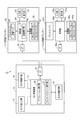
図2は、交換前プリンター11a、及び、交換後プリンター11の各種スペックを示す図であり、(A)は交換前プリンター11aを、(B)は交換後プリンター11をそれぞれ示している。また、図3は、フォントA、フォントB、フォントA’、及び、フォントB’のフォントサイズを示す図である。
以下の説明では、交換前プリンター11a、及び、交換後プリンター11は共に、80mm幅の感熱ロール紙24を収容していることを前提としているものとする。
図2(A)に示すように、交換前プリンター11aの記録解像度は、180dpiである。
また、感熱ロール紙24の幅が80mmの場合の交換前プリンター11aの最大印字領域幅は512ドットである。最大印字領域幅とは、幅方向に形成可能な画素の最大数のことであり、感熱ロール紙24の幅が80mmの場合、記録解像度が180dpiであることとの関係上、最大印字領域幅は512ドットとなる。
また、交換前プリンター11aは、フォントA、及び、フォントBの2種類のフォントに対応しており、フォントAに係るフォントテーブルであるフォントAテーブル40a、及び、フォントBに係るフォントテーブルであるフォントBテーブル41aがそれぞれ記憶部35aに記憶されている。
フォントテーブルとは、フォントデータを集合して記憶するテーブルであり、また、フォントデータとは、文字を感熱ロール紙24に記録可能な態様で表現する実データのことである。本実施形態では、フォントデータの態様は、ビットマップフォントデータである。フォントデータの態様としては、ビットマップデータのほか、スケイラブルフォントデータや、ベクトルフォントデータ、アウトラインフォントデータ等がある。なお、図3に示すように、フォントAのフォントサイズは、横12ドット×縦24ドットであり、フォントBのフォントサイズは、横9ドット×縦17ドットである。
また、交換前プリンター11aのフォントAに係る文字の記録可能桁数は42桁であり、フォントBに係る文字の記録可能桁数は56桁である。記録可能桁数とは、1のフォントに係る文字を1行に連続して記録可能な桁数のことである。図2(A)に示すように、80mm幅の感熱ロール紙24では最大印字領域幅が512ドットであるため、フォントAに係る文字の記録可能桁数は、42桁(512/12=42.6・・・)となり、フォントBに係る文字の記録可能桁数は、56桁(512/56.8・・・)となる。
2A and 2B are diagrams showing various specifications of the pre-replacement printer 11a and the post-replacement printer 11. FIG. 2A shows the pre-replacement printer 11a, and FIG. 2B shows the post-replacement printer 11. FIG. 3 is a diagram showing font sizes of font A, font B, font A ′, and font B ′.
In the following description, it is assumed that both the pre-replacement printer 11a and the post-replacement printer 11 contain an 80 mm wide
As shown in FIG. 2A, the recording resolution of the pre-replacement printer 11a is 180 dpi.
Further, when the width of the
The pre-replacement printer 11a supports two types of fonts, font A and font B, and a font A table 40a that is a font table related to font A and a font that is a font table related to font B. Each B table 41a is stored in the
The font table is a table that stores font data in a collective manner, and the font data is actual data that expresses characters in a manner that can be recorded on the
In addition, the recordable number of characters related to the font A of the pre-replacement printer 11a is 42 digits, and the recordable number of characters related to the font B is 56 digits. The recordable digit number is the number of digits that can be continuously recorded in one line for a character related to one font. As shown in FIG. 2A, since the maximum print area width is 512 dots in the 80 mm wide
次いで、上述したスペックの交換前プリンター11aが、ある一連の文字列を記録する際の動作について簡単に説明する。 Next, a brief description will be given of the operation when the above-described printer 11a before specification recording records a certain series of character strings.
図4(A)は、所定の文字列の記録を指示する制御コマンドの一例を模式的に示す図であり、図4(B)は、図4(A)に示す制御コマンドを実行することにより文字列が記録された感熱ロール紙24の様子を示す図である。
図4(A)において、コマンド群H1は、フォントAによって文字列「AAA・・・A」(文字「A」が42個(=記録可能桁数)連続した文字列。以下、同じ。)の記録を指示する制御コマンドの一例を示している。
コマンド群H1は、フォント指定コマンドFC1と、文字列記録指示コマンドMC1とを含んでいる。
フォント指定コマンドFCとは、文字列を記録するときのフォントを指定するコマンドであり、コマンド群H1のフォント指定コマンドFC1は、文字列を記録するときのフォントとしてフォントAを指定している。
また文字列記録指示コマンドMCとは、文字列を記録することを指示するコマンドである。文字列記録指示コマンドMCは、命令コードと、所定の文字コード(例えば、アスキーコード。)で表現された文字の組み合わせからなる文字列と、が組み合わされて構成されている。コマンド群H1の文字列記録指示コマンドMC1は、「XXX“AAA・・・A”」(ただし、XXXは、文字列を記録することを指示する命令コード。また、ダブルクォーテーション内の文字列は、アスキーコードで表現された文字の組み合わせによって構成された文字列。)という構成となっている。
また、図4(A)において、コマンド群H2は、フォントBによって文字列「BBB・・・B」(文字「B」が57個(=記録可能桁数+1)連続した文字列。以下、同じ。)の記録を指示する制御コマンドの一例を示している。
コマンド群H2は、フォント指定コマンドFC2と、文字列記録指示コマンドMC2とを含んでいる。フォント指定コマンドFC2は、文字列を記録するときのフォントとしてフォントBを指定している。文字列記録指示コマンドMC2は、文字列「BBB・・・B」を記録することを指示している。
FIG. 4A is a diagram schematically showing an example of a control command for instructing recording of a predetermined character string, and FIG. 4B is executed by executing the control command shown in FIG. It is a figure which shows the mode of the
In FIG. 4A, a command group H1 is a character string “AAA... A” (a character string in which 42 characters (A) are continuous (= number of recordable digits) by font A. The same applies hereinafter). An example of a control command for instructing recording is shown.
The command group H1 includes a font designation command FC1 and a character string recording instruction command MC1.
The font designation command FC is a command for designating a font for recording a character string, and the font designation command FC1 of the command group H1 designates the font A as a font for recording a character string.
The character string recording instruction command MC is a command for instructing to record a character string. The character string recording instruction command MC is configured by combining an instruction code and a character string formed by a combination of characters expressed by a predetermined character code (for example, ASCII code). The character string recording instruction command MC1 of the command group H1 is “XXX“ AAA... A ”” (where XXX is an instruction code for instructing recording of a character string. Also, a character string in double quotations is: A character string composed of a combination of characters expressed in ASCII code.).
4A, the command group H2 is a character string in which the character string “BBB... B” (character “B” is 57 characters (= number of recordable digits + 1) continuously by the font B. The same applies hereinafter. .) Shows an example of a control command for instructing recording.
The command group H2 includes a font designation command FC2 and a character string recording instruction command MC2. The font designation command FC2 designates the font B as a font for recording a character string. The character string recording instruction command MC2 instructs to record the character string “BBB... B”.
まず、コマンド群H1に基づいて、フォントAで文字列「AAA・・・A」を記録する場合の交換前プリンター11aの動作について簡単に説明する。上述したように、ホストコンピューター10からコマンド群H1のフォント指定コマンドFC1、及び、文字列記録指示コマンドMC1を受信すると、各コマンドは受信バッファーに一時的に格納される。
まず、交換前プリンター11aの制御部30aは、受信バッファーに格納されたフォント指定コマンドFC1、及び、文字列記録指示コマンドMC1を読み出す。
次いで、制御部30aは、文字列記録指示コマンドMC1が指定する文字列(文字列「AAA・・・A」)を構成する文字を順番に取得し、フォント指定コマンドFC1が指定するフォント(フォントA)のフォントテーブル(フォントAテーブル40a)を参照して、取得した文字をフォントデータに変換する。ここで、アスキーコードで表現された文字のそれぞれは、フォントテーブルに記憶されたいずれかのフォントデータと対応関係にあり、この対応関係を示す情報が記憶部35aに予め記憶されている。
次いで、制御部30aは、変換したフォントデータを、順次、行バッファー45aに展開する。
First, the operation of the pre-replacement printer 11a when the character string “AAA... A” is recorded in the font A based on the command group H1 will be briefly described. As described above, when the font designation command FC1 of the command group H1 and the character string recording instruction command MC1 are received from the
First, the
Next, the
Next, the
図5(A)は、行バッファー45aにフォントデータが展開される様子を示す図である。
行バッファー45aとは、制御部30aのRAMの所定の記憶領域に形成された、1行分のプリントバッファーのことである。文字列の記録は、行ごとに行われる構成となっており、感熱ロール紙24上のある1行に文字列を記録する場合、制御部30aは、当該文字列を構成する全ての文字のフォントデータを、行バッファー45aに展開した後、行バッファー45aに展開されているデータに基づいて、画像を記録する。
交換前プリンター11aでは、行バッファー45aの横方向(感熱ロール紙24の幅方向に対応する方向)のサイズは、512ドットである。これは、交換前プリンター11aの最大印字領域幅が512ドットだからである。
行バッファー45aにフォントAに係るフォントデータが展開される動作をより具体的に説明すると、制御部30aは、まず、RAMに横512ドット、縦24ドットの行バッファー45aを形成する。行バッファー45aの縦のサイズは、展開するフォントデータのフォントサイズによって規定される。
次いで、制御部30aは、図5(A)に示すように、文字列「AAA・・・A」を構成する42個の文字のうち、処理対象となっている1つの文字を取得し、取得した文字をフォントデータに変換し、変換したフォントデータを行バッファー45aに展開する、という動作を順番に行うことにより、文字列「AAA・・・A」を構成する42個の文字のフォントデータを、矢印Y1方向に向かって、順次、行バッファー45aに展開する。フォントAのフォントサイズは、横12×縦24であるため、横512ドットの行バッファー45aに、42個全てのフォントデータを展開可能である。そして、文字列「AAA・・・A」を構成する42個全ての文字のフォントデータを行バッファー45aに展開した後、制御部30aは、行バッファー45aに展開されているデータに基づいて、プリントエンジン33を制御して画像を記録する。
なお、記録可能桁数とは、すなわち、行バッファー45aに展開可能なフォントデータの数の最大数のことである。つまり、行バッファー45aの横方向のサイズが512ドットであり、フォントAの横のサイズが12ドットであるため、フォントAのフォントデータは行バッファー45aに最大42個、展開可能(=1行に最大42桁、フォントAに係る文字を記録可能)であり、従って、フォントAに係る文字の記録可能桁数は、42桁ということとなる。同様に、フォントBのフォントデータは行バッファー45aに最大56個、展開可能(=1行に最大42桁、フォントBに係る文字を記録可能)であり、従って、フォントBに係る文字の記録可能桁数は、56桁ということとなる。
FIG. 5A is a diagram showing how font data is expanded in the
The
In the pre-replacement printer 11a, the size of the
The operation of expanding the font data related to the font A in the
Next, as illustrated in FIG. 5A, the
Note that the recordable digit number is the maximum number of font data that can be expanded in the
次いで、コマンド群H2に基づいて、フォントBで文字列「BBB・・・B」を記録する場合の交換前プリンター11aの動作、特に、行バッファー45aに文字列「BBB・・・B」に係るフォントデータを展開する際の動作について簡単に説明する。文字列「BBB・・・B」は、文字「B」が57個連続した文字列であり、その桁数が、記録可能桁数(=56個)を上回っている。
図5(B1)に示すように、文字列「BBB・・・B」のそれぞれの文字のフォントデータ(フォントB)を順次展開していった場合、行バッファー45aの横のサイズが512ドットであり、フォントBの横のサイズが9ドットであるため、56個目の文字「B」のフォントデータを展開した後は、57個目の文字「B」のフォントデータを行バッファー45aに展開できない状態となる。この状態が現出した場合、制御部30aは、行バッファー45aがフルになったと判別し、行バッファー45aに展開されたデータに基づいて、56個分の文字「B」の記録を行う。その後、制御部30aは、行バッファー45aをバッファークリアし、残りの文字のフォントデータを行バッファー45aの先頭から順次展開する。具体的には、57個目の文字「B」のフォントデータを行バッファー45aに展開する(図5(B2))。次いで、制御部30aは、行バッファー45aに展開されたデータに基づいて、57個目の文字「B」を記録する。
Next, based on the command group H2, the operation of the pre-replacement printer 11a when the character string “BBB... B” is recorded in the font B, particularly the character string “BBB... B” in the
As shown in FIG. 5B1, when the font data (font B) of each character of the character string “BBB... B” is sequentially developed, the horizontal size of the
次いで、交換後プリンター11のスペックについて説明する。
図2(B)に示すように、交換後プリンター11の記録解像度は、203dpiである。
また、感熱ロール紙24の幅が80mmの場合の交換前プリンター11aの最大印字領域幅は、記録解像度が203dpiであることとの関係上、576ドットである。
また、交換後プリンター11は、フォントA’、及び、フォントB’の2種類のフォントに対応しており、フォントA’に係るフォントテーブルであるフォントA’テーブル40、及び、フォントBに係るフォントテーブルであるフォントB’テーブル41がそれぞれ記憶部35に記憶されている。なお、図3に示すように、フォントA’のフォントサイズは、横13ドット×縦26ドットであり、フォントB’のフォントサイズは、横10ドット×縦19ドットである。
実際印字領域幅、左マージン、及び、実際記録可能桁数については後述する。
Next, the specifications of the printer 11 after replacement will be described.
As shown in FIG. 2B, the recording resolution of the printer 11 after replacement is 203 dpi.
Further, when the width of the
Further, the printer 11 after replacement corresponds to two types of fonts, font A ′ and font B ′, and the font A ′ table 40 which is a font table related to the font A ′ and the font related to the font B. A font B ′ table 41 which is a table is stored in the
The actual print area width, left margin, and actual recordable number of digits will be described later.
さて、図2における交換前プリンター11aのスペックと、交換後プリンター11のスペックとの比較によって明らかなように、交換後プリンター11と、交換前プリンター11aとでは、記録解像度、及び、記憶するフォントデータのフォントサイズが異なっている。
フォントサイズの相違について詳述すると、交換前プリンター11aは、横12×縦24のフォントAのフォントデータを記憶している。一方、交換後プリンター11は、フォントAのフォントサイズと同一のフォントサイズのフォントに係るフォントデータを記憶しておらず、比較的フォントサイズが近いフォントA’(横13×縦26)のフォントデータを記憶している。
同様に、交換前プリンター11aは、横9×縦17のフォントBのフォントデータを記憶している。一方、交換後プリンター11は、フォントBのフォントサイズと同一のフォントサイズのフォントに係るフォントデータを記憶しておらず、比較的フォントサイズが近いフォントB’(横10×縦19)のフォントデータを記憶している。
そして、交換前プリンター11aから交換後プリンター11にホストコンピューター10に接続されるプリンターが交換された場合であっても、ホストコンピューター10が送信するコマンドの内容の変更を伴うことなく、交換後プリンター11は、以下の動作を実行することにより、フォントA’に係る文字の記録可能桁数を42桁に調整すると共に、フォントB’に係る文字の記録可能桁数を56桁に調整し、これにより、交換の前後で記録結果が近似するようにしている。
As is apparent from a comparison between the specifications of the pre-replacement printer 11a and the post-replacement printer 11 in FIG. 2, the post-replacement printer 11 and the pre-replacement printer 11a have the recording resolution and the font data to be stored. The font size is different.
The difference in font size will be described in detail. The pre-replacement printer 11a stores font data of a font A of horizontal 12 × vertical 24. On the other hand, the post-replacement printer 11 does not store font data related to a font having the same font size as the font size of the font A, and font data of the font A ′ (13 horizontal × 26 vertical) having a relatively close font size. Is remembered.
Similarly, the pre-replacement printer 11a stores font data of font B of 9 × 17 font B. On the other hand, the post-replacement printer 11 does not store font data relating to a font having the same font size as the font size of font B, and font data of font B ′ (horizontal 10 × vertical 19) having a relatively close font size. Is remembered.
Even when the printer connected to the
図6は、交換後プリンター11の動作を示すフローチャートである。
図6のフローチャートでは、特に、フォント指定コマンドFC、及び、文字列記録指示コマンドMCを含むコマンド群Hを読み出して実行する際の交換後プリンター11の動作を示している。
図6のフローチャートの前提として、交換後プリンター11は、ホストコンピューター10からフォント指定コマンドFC、及び、文字列記録指示コマンドMCを含むコマンド群Hを受信しており、このコマンド群Hが受信バッファーに格納されている状態であるものとする。
まず、交換後プリンター11の制御部30の記録実行部37は、受信バッファーに格納されたコマンド群Hを読み出す(ステップSA1)。
ここで、プリンターの交換前後において、ホストコンピューター10が送信する制御コマンドの内容に変化はなく、ホストコンピューター10は、あくまで、交換前プリンター11aが接続されていることを前提として、交換前プリンター11aに準じた制御コマンドを生成し、送信する。従って、ホストコンピューター10が送信するフォント指定コマンドFCは、交換前プリンター11aが対応しているフォントA、又は、フォントBのいずれかを指定している。上述したように、交換後プリンター11において、フォントAに対応しているフォントは、フォントA’であり、また、フォントBに対応しているフォントは、フォントB’である。
FIG. 6 is a flowchart showing the operation of the printer 11 after replacement.
The flowchart of FIG. 6 particularly shows the operation of the printer 11 after replacement when the command group H including the font designation command FC and the character string recording instruction command MC is read and executed.
As a premise of the flowchart of FIG. 6, the post-replacement printer 11 receives a command group H including a font designation command FC and a character string recording instruction command MC from the
First, the
Here, there is no change in the content of the control command transmitted by the
次いで、記録実行部37は、文字列記録指示コマンドMCが指定する文字列を構成する文字のうち、処理対象となる文字(以下、単に「処理対象文字」という。)を取得する(ステップSA2)。ステップSA2は、巡回的に実行されるステップであり、ステップSA2では、文字列記録指示コマンドMCが指定する文字列を構成する文字のそれぞれが、順番に、処理対象文字となる。例えば、文字列記録指示コマンドMCが指定する文字列が文字列「ABC」である場合は、1回目にステップSA2が実行されるときの処理対象文字は文字「A」となり、2回目にステップSA2が実行されるときの処理対象文字は文字「B」となり、そして、3回目にステップSA2が実行されるときの処理対象文字は文字「C」となる。
Next, the
次いで、記録実行部37は、実際印字領域幅(後述)が設定されているか否かを判別する(ステップSA3)。なお、実際印字領域幅は、後述するステップSA6、又は、ステップSA8において設定されることとなるが、具体的には、文字列記録指示コマンドMCが指定する文字列のうち、先頭の文字が処理対象文字対象となっている場合、又は、一旦、行バッファー45がフルとなって(ステップSA14:YES)、記録が実行され(ステップSA15)、行バッファー45が消去されると共に(ステップSA16)、実際印字領域幅の設定が解除された場合(ステップSA17)に、実際印字領域幅が設定されていない状態となる。
実際印字領域幅が設定されていない場合(ステップSA3:YES)、記録実行部37は、ステップSA1で読み出したフォント指定コマンドFCが指定するフォントがフォントAであるか、フォントBであるかを判別する(ステップSA4)。
フォント指定コマンドFCが指定するフォントがフォントAである場合(ステップSA4:「フォントA」)、記録実行部37は、RAM上に、フォントAに対応するフォントA’に準じた行バッファー45を形成する(ステップSA5)。具体的には、記録実行部37は、横576ドット、縦26ドットの行バッファー45を形成する。行バッファー45の横方向のサイズは、最大印字領域幅に応じて規定され、縦方向のサイズは、フォントA’の縦方向のサイズに応じて規定される。
次いで、記録実行部37は、実際印字領域幅を「546ドット」に設定すると共に、左マージンを「15ドット」に設定する(ステップSA6)。
Next, the
If the actual print area width is not set (step SA3: YES), the
When the font designated by the font designation command FC is font A (step SA4: “font A”), the
Next, the
図7(A)は、実際印字領域幅を説明すべく、ステップSA5で形成された行バッファー45を模式的に示す図である。
上述したように、行バッファー45の横方向のサイズは、最大印字領域幅が576ドットであるため、これに対応して576ドットとなっている。この行バッファー45の横方向のサイズは固定値である。
ここで、仮に、ステップSA5で形成した行バッファー45に、そのまま、フォントA’のフォントデータを展開したとする。この場合、行バッファー45にフォントA’のフォントデータを44個(576/13=44.3・・・)展開できることとなり、これに伴って、記録可能桁数が44桁となる。この場合、交換前プリンター11aによってフォントAの文字を記録したときの記録可能桁数(42桁)と、交換後プリンター11によってフォントA’の文字を記録したときの記録可能桁数(44桁)との間に乖離が生じる結果となる。上述したように、記録可能桁数の乖離は、文字列の改行位置の相違を生じたり、また、行における文字列の位置のバランスの相違を生じたりするため、記録結果の近似性を阻害する要因となる。
これを踏まえ、本実施形態では、フォントA’のフォントデータを行バッファー45に展開する場合、記録実行部37は、行バッファー45において、フォントA’のフォントデータが42個展開可能なサイズの領域を、実際にフォントデータが展開可能な領域(以下、「展開可能領域」という。)として設定する。そして、この展開可能領域のサイズ(横方向のドット数)が、実際印字領域幅である。ここで、フォントA’の横方向のサイズは13ドットであるため、フォントA’に係る実際印字領域幅は、546ドット(13×42)である。これを踏まえ、ステップSA6において、記録実行部37は、実際印字領域幅を546ドットに設定する。実際印字領域幅を546ドットと設定することにより、図7(A)に示すように、展開可能領域に展開可能なフォントA’のフォントデータの数が42個となり、これに伴って、実際のフォントA’に係る文字の記録可能桁数(以下、「実際記録可能桁数」という。)は、42桁となる。
FIG. 7A is a diagram schematically showing the
As described above, the horizontal size of the
Here, it is assumed that the font data of the font A ′ is expanded as it is in the
Based on this, in the present embodiment, when the font data of the font A ′ is expanded in the
左マージンとは、図7(A)に示すように、行バッファー45において、展開可能領域の先頭側(図7(A)中左側)に形成されるマージンのことである。左マージンの値によって、行バッファー45における展開可能領域の相対的な位置が決定する。
左マージンは、行バッファー45の中央部に展開可能領域が配置されるような値とされる。行バッファー45の中央部に展開可能領域が配置されるようにすることにより、行バッファー45に展開されたデータに基づいて文字列の記録を行った場合に、感熱ロール紙24における偏った位置に文字列が記録されることを防止できるからである。
以上を踏まえ、ステップSA6において、記録実行部37は、左マージンを15ドットに設定する。これにより、図7(A)に示すように、行バッファー45の中央部に展開可能領域が配置されることとなる。
As shown in FIG. 7A, the left margin is a margin formed on the top side of the developable area (left side in FIG. 7A) in the
The left margin is set to a value such that a developable area is arranged at the center of the
Based on the above, in step SA6, the
一方、ステップSA4において、フォント指定コマンドFCが指定するフォントがフォントBである場合(ステップSA4:「フォントB」)、記録実行部37は、RAM上に、フォントBに対応するフォントB’に準じた行バッファー45を形成する(ステップSA7)。具体的には、記録実行部37は、横576ドット、縦19ドットの行バッファー45を形成する。行バッファー45の横方向のサイズは、最大印字領域幅に応じて規定され、縦方向のサイズは、フォントB’の縦方向のサイズに応じて規定される。
次いで、記録実行部37は、実際印字領域幅を「560ドット」に設定すると共に、左マージンを「8ドット」に設定する(ステップSA8)。
ステップSA8において、実際印字領域幅が「560ドット」に設定されるのは、以下の理由による。
すなわち、交換前プリンター11aにおけるフォントBの記録可能桁数が56桁であることを踏まえ、記録実行部37は、交換後プリンター11におけるフォントB’(横10×縦19)の実際記録可能桁数を56桁とすべく、実際印字領域幅を560ドット(10×56)とする。また、記録実行部37は、行バッファー45の中央部に展開可能領域配置すべく左マージンが「8ドット」に設定する。
このように、実際印字領域幅、及び、左マージンが設定されることにより、図7(B)に示すように、行バッファー45に形成された展開可能領域に展開可能なフォントB’のフォントデータの数が56個となり、これに伴って、実際のフォントB’に係る文字の実際記録可能桁数は、56桁となる。また、行バッファー45の中央部に展開可能領域が配置されることとなる。
On the other hand, when the font designated by the font designation command FC is font B in step SA4 (step SA4: “font B”), the
Next, the
In step SA8, the actual print area width is set to “560 dots” for the following reason.
That is, based on the fact that the number of recordable digits of font B in the printer 11a before replacement is 56, the
In this way, by setting the actual print area width and the left margin, as shown in FIG. 7B, the font data of the font B ′ that can be developed in the developable area formed in the
ステップSA6、又は、ステップSA8を実行後、記録実行部37は、処理手順をステップSA9へ移行する。
ステップSA9において、記録実行部37は、フォント指定コマンドFCが指定するフォントに対応するフォントテーブルを参照する。具体的には、フォント指定コマンドFCが指定するフォントがフォントAである場合は、このフォントAに対応するフォントA’に係るフォントA’テーブル40を参照し、また、フォント指定コマンドFCが指定するフォントがフォントBである場合は、このフォントBに対応するフォントB’に係るフォントB’テーブル41を参照する。
次いで、記録実行部37は、処理対象文字をフォントデータに変換する(ステップSA10)。上述したように、フォントテーブルに記憶された各フォントデータと、各文字のアスキーコードとの対応関係を示す情報が記憶部35に記憶されているため、記録実行部37は、当該情報に基づいて、処理対象文字をフォントデータに変換する。
次いで、記録実行部37は、変換したフォントデータを行バッファー45に展開する(ステップSA11)。
次いで、記録実行部37は、文字列記録指示コマンドMCが指定する文字列を構成する文字の全てが処理対象文字となったか否かを判別する(ステップSA12)。
文字列を構成する文字に1つでも処理対象文字となっていない文字が存在する場合(ステップSA12:NO)、記録実行部37は、処理手順をステップSA2へ戻す。
一方、文字列を構成する全ての文字が処理対象文字となった場合(ステップSA12:YES)、記録実行部37は、行バッファー45に展開されているデータに基づいて、プリントエンジン33を制御して、感熱ロール紙24への画像の記録を実行し(ステップSA13)、処理を終了する。
After executing Step SA6 or Step SA8, the
In step SA9, the
Next, the
Next, the
Next, the
If at least one character constituting the character string is not a character to be processed (step SA12: NO), the
On the other hand, when all the characters constituting the character string have been processed (step SA12: YES), the
一方、ステップSA3において、実際印字領域幅が設定されている場合(ステップSA3:NO)、記録実行部37は、行バッファー45がフルか否かを判別する(ステップSA14)。
ここで、行バッファー45がフルとは、行バッファー45に形成された展開可能領域にこれ以上フォントデータを展開できない状態のことを言う。上述したように、フォント指定コマンドFCが指定するフォントがフォントAの場合は、展開可能領域のサイズ(実際印字領域幅)は546ドットに設定されるため、フォントA’のフォントデータが42個展開された段階でフルとなり、また、フォント指定コマンドFCが指定するフォントがフォントBの場合は、展開可能領域のサイズ(実際印字領域幅)は560ドットに設定されるため、フォントB’のフォントデータが56個展開された段階でフルとなる。
行バッファー45がフルではない場合(ステップSA14:NO)、記録実行部37は、処理手順をステップSA9へ移行し、行バッファー45への処理対象文字に係るフォントデータの展開に係る処理を実行する。
一方、行バッファー45がフルの場合(ステップSA14:YES)、記録実行部37は、行バッファー45に展開されているデータに基づいて、プリントエンジン33を制御して、感熱ロール紙24への画像の記録を実行する(ステップSA15)。
ステップSA15では、フォント指定コマンドFCが指定するフォントがフォントAの場合は、42桁分のフォントA’に係る文字が記録されることとなり、また、フォント指定コマンドFCが指定するフォントがフォントBの場合は、56桁分のフォントB’に係る文字が記録されることとなる。
次いで、記録実行部37は、行バッファー45消去する(ステップSA16)。
次いで、記録実行部37は、実際印字領域幅の設定を解除すると共に、左マージンの設定を解除し(ステップSA17)、処理手順をステップSA3へ移行する。以後、再び、行バッファー45の形成、及び、行バッファー45へのフォントデータの展開が、順次、実行されることとなる。
On the other hand, if the actual print area width is set in step SA3 (step SA3: NO), the
Here, the
If the
On the other hand, when the
In step SA15, when the font designated by the font designation command FC is font A, the characters relating to the 42-digit font A 'are recorded, and the font designated by the font designation command FC is font B. In this case, 56-digit characters related to the font B ′ are recorded.
Next, the
Next, the
以上説明したように、本実施形態では、記録実行部37は、ホストコンピューター10から文字列の記録を指示する文字列記録指示コマンドMCを受信した場合、実際印字領域幅を調整することにより、フォントデータに基づく文字の記録可能桁数を調整した上で、当該文字列に対応するフォントデータに基づいて記録を行う。
これによれば、ホストコンピューター10から文字列記録指示コマンドMCを受信した場合、実際印字領域幅を調整することにより、記録可能桁数を調整した上で、当該文字列に対応するフォントデータに基づいて記録を行うため、交換の前後で記録可能桁数を一致させることが可能となる。特に、ホストコンピューター10が送信する制御コマンドの内容を変更することなく、交換後プリンター11側で、自動で、記録可能桁数の調整行う構成のため、記録可能桁数を一致させるためにホストコンピューター10に何らかの改変を加えたり、記録に係る各種設定を調整したりする必要がない。
As described above, in the present embodiment, when the
According to this, when the character string recording instruction command MC is received from the
また、本実施形態では、記録実行部37は、交換前プリンター11aと交換後プリンター11との記録解像度の相違、及び、交換前プリンター11aが記憶するフォントデータのフォントサイズと、交換後プリンター11が記憶するフォントデータのフォントサイズとの相違を反映して、交換前プリンター11aにおけるフォントAの記録可能桁数と、交換後プリンター11におけるフォントA’の記録可能桁数が共に42桁となるように実際印字領域幅を調整し、また、交換前プリンター11aにおけるフォントBの記録可能桁数と、交換後プリンター11におけるフォントB’の記録可能桁数が共に56桁となるように実際印字領域幅を調整する。
これによれば、プリンターの交換の前後でホストコンピューター10からプリンターに送信する制御コマンドの内容を変更することなく、交換の前後で、記録可能桁数を一致させることができる。特に、記録可能桁数を一致させるためにホストコンピューター10に対して何らかの改変を加えたり、記録に係る各種設定を調整したりする必要がない。
Further, in the present embodiment, the
According to this, the number of recordable digits can be matched before and after the replacement without changing the content of the control command transmitted from the
また、本実施形態では、行バッファー45の中央部に展開可能領域が配置される。
これにより、行バッファー45に展開されたデータに基づいて文字列の記録を行った場合に、感熱ロール紙24における偏った位置に文字列が記録されることを防止できる。
In the present embodiment, a developable area is arranged at the center of the
Thereby, when the character string is recorded based on the data developed in the
なお、上述した実施の形態は、あくまでも本願発明の一態様を示すものであり、本願発明の範囲内で任意に変形および応用が可能である。
例えば、上述した実施形態では、交換前プリンター11a、及び、交換後プリンター11について、記録解像度、及び、フォンデータのフォントサイズの双方が異なる場合を例にして発明を説明した。しかしながら、記録解像度、及び、フォンデータのフォントサイズのいずれか一方が異なる場合であっても、本願発明を適用可能である。すなわち、記録解像度の相違、又は、フォントデータのフォントサイズの相違を反映して、実際印字領域幅を調整し、実際記録可能桁数を調整することにより、交換の前後で、記録可能桁数を一致させることができ、記録結果を近似させることが可能となる。
The above-described embodiment is merely an aspect of the present invention, and can be arbitrarily modified and applied within the scope of the present invention.
For example, in the above-described embodiment, the invention has been described with respect to the case where both the recording resolution and the font size of the phone data are different for the pre-replacement printer 11a and the post-replacement printer 11. However, the present invention can be applied even when either the recording resolution or the font size of the phone data is different. That is, the actual print area width is adjusted to reflect the difference in recording resolution or the font size of the font data, and the actual recordable number of digits is adjusted, so that the number of recordable digits is changed before and after the replacement. It is possible to match, and it is possible to approximate the recording result.
また、例えば、図1に示す各機能部はハードウェアとソフトウェアの協働により任意に実現可能であり、特定のハードウェア構成を示唆するものではない。
また、上述した実施形態では、交換後プリンター11自体が制御部30を備えていたが、例えば、制御部30の機能を、交換後プリンター11に外部接続される別の装置に持たせるようにしても良い。
また、本願発明は、サーマル式のプリンターに限らず、インクジェット式プリンター、ドットインパクト式プリンター、レーザープリンター、熱昇華型プリンター等の任意の形式のプリンターに適用可能である。また、ATMにおけるプリンター等、他の装置に組み込まれるプリンターであってもよい。また、CDのレーベル面や、DVDのレーベル面等の紙以外の媒体に記録するものでもよい。
また、本願発明を適用可能なプログラムは、ホストコンピューター10に搭載されるプリンタードライバーに含むものであってもよい。
また、上記のフローチャートの各ステップを実行するプログラムを、交換後プリンター11の外部の記憶媒体に記憶させたものを読み出して、制御部30により実行させることもできる。
Further, for example, each functional unit shown in FIG. 1 can be arbitrarily realized by cooperation of hardware and software, and does not suggest a specific hardware configuration.
In the above-described embodiment, the printer 11 after replacement has the
The present invention is not limited to a thermal printer, but can be applied to an arbitrary type of printer such as an ink jet printer, a dot impact printer, a laser printer, or a thermal sublimation printer. Moreover, the printer incorporated in other apparatuses, such as a printer in ATM, may be used. Further, it may be recorded on a medium other than paper, such as a CD label surface or a DVD label surface.
A program to which the present invention can be applied may be included in a printer driver mounted on the
In addition, a program that executes each step of the above-described flowchart may be read out and stored in a storage medium outside the printer 11 after replacement, and executed by the
1…記録システム、10…ホストコンピューター(制御装置)、11…交換後プリンター(記録装置)、11a…交換前プリンター(他の記録装置)、30…制御部、37…記録実行部。 DESCRIPTION OF SYMBOLS 1 ... Recording system, 10 ... Host computer (control apparatus), 11 ... Printer after replacement | exchange (recording apparatus), 11a ... Printer before replacement | exchange (other recording apparatus), 30 ... Control part, 37 ... Recording execution part.
Claims (4)
前記記録紙の幅方向に前記第1のフォントサイズと異なる第2のフォントサイズの第2のフォントデータを指定するコマンド及び1又は複数の文字を有する文字列の記録を指示するコマンドを含む制御コマンドを受信する受信部と、
前記受信部で前記制御コマンドを受信した場合、設定された印字領域幅に前記第1のフォントデータに基づいて記録する記録実行部と、を備え、
前記記録実行部は、前記受信部で前記制御コマンドを受信した場合、前記第1のフォントデータで文字を記録したときの1行における最大記録可能桁数と、前記第2のフォントデータで文字を記録したときの1行における最大記録可能桁数とが同一となるように、前記文字列が記録される行の前記印字領域幅を設定し、設定された前記印字領域幅に前記第1のフォントデータに基づいて記録することを特徴とする記録装置。 A storage unit for storing first font data of a first font size in the width direction of the recording paper;
A control command including a command designating second font data having a second font size different from the first font size in the width direction of the recording paper and a command designating recording of a character string having one or more characters A receiving unit for receiving
A recording execution unit for recording in the set print area width based on the first font data when the receiving unit receives the control command ;
The recording execution unit, when receiving the control command at the receiving unit, records the maximum recordable number of digits in one line when the character is recorded with the first font data and the character with the second font data. The print area width of the line in which the character string is recorded is set so that the maximum recordable number of digits in one line at the time of recording is the same, and the first font is set to the set print area width. recording apparatus characterized that you recorded based on the data.
前記記録紙の幅方向に前記第1のフォントサイズと異なる第2のフォントサイズの第2のフォントデータを指定するコマンド及び1又は複数の文字を有する文字列の記録を指示するコマンドを含む制御コマンドを受信し、
前記第1のフォントデータで文字を記録したときの1行における最大記録可能桁数と、前記第2のフォントデータで文字を記録したときの1行における最大記録可能桁数とが同一となるように、前記文字列が記録される行の印字領域幅を設定し、
設定された前記印字領域幅に前記第1のフォントデータに基づいて記録することを特徴とする記録装置の制御方法。 Storing first font data of a first font size in the width direction of the recording paper;
A control command including a command designating second font data having a second font size different from the first font size in the width direction of the recording paper and a command designating recording of a character string having one or more characters Receive
The maximum recordable digit number in one line when a character is recorded with the first font data is the same as the maximum recordable digit number in one line when a character is recorded with the second font data. Set the print area width of the line in which the character string is recorded,
Control method for a recording apparatus which is characterized in that recording based on the set the print area width in the first font data.
前記制御コマンドが受信された場合、前記第1のフォントデータで文字を記録したときの1行における最大記録可能桁数と、前記第2のフォントデータで文字を記録したときの1行における最大記録可能桁数とが同一となるように、前記文字列が記録される行の前記印字領域幅を設定させ、設定された前記印字領域幅に前記第1のフォントデータに基づいて記録させることを特徴とする画像補正プログラム。 First font data storage makes storage means of the first font size computers in the width direction of the recording sheet, a second font of a second font size being different from the width direction of the recording paper first font size A receiving unit for receiving a control command including a command for specifying data and a command for instructing recording of a character string having one or more characters , and a print area width set when the receiving unit receives the control command An image correction program for functioning as a recording execution means for recording on the basis of the first font data ,
When the control command has been received, the maximum recording in one row when the recording and the maximum recordable number of digits, a character in the second font data in one row when the record characters in said first font data as can the digits are the same, the character string is set to the print area width line to be recorded, that is recorded on the basis of the first font data to the set the print area width A featured image correction program.
Priority Applications (1)
| Application Number | Priority Date | Filing Date | Title |
|---|---|---|---|
| JP2011126614A JP5891610B2 (en) | 2011-06-06 | 2011-06-06 | RECORDING DEVICE, RECORDING DEVICE CONTROL METHOD, AND IMAGE CORRECTION PROGRAM |
Applications Claiming Priority (1)
| Application Number | Priority Date | Filing Date | Title |
|---|---|---|---|
| JP2011126614A JP5891610B2 (en) | 2011-06-06 | 2011-06-06 | RECORDING DEVICE, RECORDING DEVICE CONTROL METHOD, AND IMAGE CORRECTION PROGRAM |
Publications (3)
| Publication Number | Publication Date |
|---|---|
| JP2012250507A JP2012250507A (en) | 2012-12-20 |
| JP2012250507A5 JP2012250507A5 (en) | 2014-07-03 |
| JP5891610B2 true JP5891610B2 (en) | 2016-03-23 |
Family
ID=47523771
Family Applications (1)
| Application Number | Title | Priority Date | Filing Date |
|---|---|---|---|
| JP2011126614A Active JP5891610B2 (en) | 2011-06-06 | 2011-06-06 | RECORDING DEVICE, RECORDING DEVICE CONTROL METHOD, AND IMAGE CORRECTION PROGRAM |
Country Status (1)
| Country | Link |
|---|---|
| JP (1) | JP5891610B2 (en) |
Families Citing this family (1)
| Publication number | Priority date | Publication date | Assignee | Title |
|---|---|---|---|---|
| JP6281400B2 (en) * | 2014-04-23 | 2018-02-21 | セイコーエプソン株式会社 | Printing apparatus and printing method of printing apparatus |
Family Cites Families (4)
| Publication number | Priority date | Publication date | Assignee | Title |
|---|---|---|---|---|
| JPH0511947U (en) * | 1991-07-31 | 1993-02-19 | 邦希 早坂 | Chemical container with horizontal nozzle |
| JP2001250077A (en) * | 2000-03-03 | 2001-09-14 | Casio Comput Co Ltd | Document processor and storage medium |
| JP5391956B2 (en) * | 2009-09-15 | 2014-01-15 | セイコーエプソン株式会社 | RECORDING DEVICE, RECORDING DEVICE CONTROL METHOD, AND PROGRAM |
| JP5532848B2 (en) * | 2009-11-20 | 2014-06-25 | セイコーエプソン株式会社 | Recording control apparatus, control method, and program |
-
2011
- 2011-06-06 JP JP2011126614A patent/JP5891610B2/en active Active
Also Published As
| Publication number | Publication date |
|---|---|
| JP2012250507A (en) | 2012-12-20 |
Similar Documents
| Publication | Publication Date | Title |
|---|---|---|
| KR101220629B1 (en) | Recording control apparatus and recording control method | |
| JP5909871B2 (en) | Recording device | |
| US9098779B2 (en) | Recording control device, control method, and program | |
| JP5891610B2 (en) | RECORDING DEVICE, RECORDING DEVICE CONTROL METHOD, AND IMAGE CORRECTION PROGRAM | |
| JP2012113608A (en) | Control device, recording system, control method of control device, and program | |
| JP5987389B2 (en) | RECORDING DEVICE, RECORDING DEVICE CONTROL METHOD, AND PROGRAM | |
| JP5754307B2 (en) | CONTROL DEVICE, CONTROL DEVICE CONTROL METHOD, AND PROGRAM | |
| US20190210377A1 (en) | Printer and printer system | |
| JP4890984B2 (en) | Printing apparatus and printing apparatus control method | |
| JP6682865B2 (en) | Printing apparatus and printing apparatus control method | |
| JP5760705B2 (en) | RECORDING DEVICE, RECORDING DEVICE CONTROL METHOD, AND PROGRAM | |
| JP6387594B2 (en) | Printing apparatus, printing apparatus control method, and program | |
| JP5810616B2 (en) | RECORDING DEVICE, RECORDING DEVICE CONTROL METHOD, AND PROGRAM | |
| JP5760375B2 (en) | RECORDING DEVICE, RECORDING DEVICE CONTROL METHOD, AND PROGRAM | |
| JP2011251456A (en) | Printing system, input device | |
| JP6032334B2 (en) | Control device and recording system | |
| JP2014054846A (en) | Control device, control method for control device, and program | |
| JP5906829B2 (en) | CONTROL DEVICE, CONTROL DEVICE CONTROL METHOD, AND PROGRAM | |
| JP5222034B2 (en) | Printing apparatus and printing apparatus control method | |
| JP2012096420A (en) | Recorder, control method for recorder, and program | |
| JPH11167476A (en) | Printing method, its device and recording medium | |
| JP2000355143A (en) | Ink-jet recording apparatus and image forming device | |
| JP2014050998A (en) | Recorder, method for controlling recorder, and program | |
| JP2013146865A (en) | Recording device, method for controlling recording device, and program | |
| JP2011173297A (en) | Controller, control method and program thereof |
Legal Events
| Date | Code | Title | Description |
|---|---|---|---|
| A521 | Written amendment |
Free format text: JAPANESE INTERMEDIATE CODE: A523 Effective date: 20140519 |
|
| A621 | Written request for application examination |
Free format text: JAPANESE INTERMEDIATE CODE: A621 Effective date: 20140519 |
|
| A131 | Notification of reasons for refusal |
Free format text: JAPANESE INTERMEDIATE CODE: A131 Effective date: 20150331 |
|
| A521 | Written amendment |
Free format text: JAPANESE INTERMEDIATE CODE: A523 Effective date: 20150521 |
|
| A131 | Notification of reasons for refusal |
Free format text: JAPANESE INTERMEDIATE CODE: A131 Effective date: 20151020 |
|
| A521 | Written amendment |
Free format text: JAPANESE INTERMEDIATE CODE: A523 Effective date: 20151120 |
|
| TRDD | Decision of grant or rejection written | ||
| A01 | Written decision to grant a patent or to grant a registration (utility model) |
Free format text: JAPANESE INTERMEDIATE CODE: A01 Effective date: 20160126 |
|
| A61 | First payment of annual fees (during grant procedure) |
Free format text: JAPANESE INTERMEDIATE CODE: A61 Effective date: 20160208 |
|
| R150 | Certificate of patent or registration of utility model |
Ref document number: 5891610 Country of ref document: JP Free format text: JAPANESE INTERMEDIATE CODE: R150 |
|
| S531 | Written request for registration of change of domicile |
Free format text: JAPANESE INTERMEDIATE CODE: R313531 |
|
| R350 | Written notification of registration of transfer |
Free format text: JAPANESE INTERMEDIATE CODE: R350 |