JP5754307B2 - CONTROL DEVICE, CONTROL DEVICE CONTROL METHOD, AND PROGRAM - Google Patents
CONTROL DEVICE, CONTROL DEVICE CONTROL METHOD, AND PROGRAM Download PDFInfo
- Publication number
- JP5754307B2 JP5754307B2 JP2011191462A JP2011191462A JP5754307B2 JP 5754307 B2 JP5754307 B2 JP 5754307B2 JP 2011191462 A JP2011191462 A JP 2011191462A JP 2011191462 A JP2011191462 A JP 2011191462A JP 5754307 B2 JP5754307 B2 JP 5754307B2
- Authority
- JP
- Japan
- Prior art keywords
- recording
- barcode
- image
- control command
- recorded
- Prior art date
- Legal status (The legal status is an assumption and is not a legal conclusion. Google has not performed a legal analysis and makes no representation as to the accuracy of the status listed.)
- Expired - Fee Related
Links
Images


Description
本発明は、記録媒体に記録する記録装置に接続可能な制御装置、当該制御装置の制御方法、及び、当該制御装置を制御するためのプログラムに関する。 The present invention relates to a control device connectable to a recording device for recording on a recording medium, a control method for the control device, and a program for controlling the control device.
従来、シート等の記録媒体にバーコードを記録するバーコード印刷システムが知られている(例えば、特許文献1参照)。 Conventionally, a barcode printing system that records a barcode on a recording medium such as a sheet is known (see, for example, Patent Document 1).
ここで、記録媒体に記録されるバーコードは、後に光学的に読み取られることが想定されている画像であり、高い精度で記録媒体に記録されることが求められている。しかしながら、従来、記録媒体に記録する記録装置がバーコードに係る画像データ(例えば、ビットマップデータ)に基づいて記録媒体にバーコードを記録する場合等に、当該画像データの解像度と、記録装置の記録解像度とがマッチしておらず、精度の高さを担保できないようなケースがあった。
本発明は、上述した事情に鑑みてなされたものであり、記録媒体にバーコードの画像を記録する際に、高い精度で記録できるようにすることを目的とする。
Here, the barcode recorded on the recording medium is an image that is supposed to be optically read later, and is required to be recorded on the recording medium with high accuracy. However, conventionally, when a recording apparatus that records on a recording medium records a barcode on a recording medium based on image data (for example, bitmap data) related to the barcode, the resolution of the image data, There were cases where the recording resolution did not match and high accuracy could not be guaranteed.
The present invention has been made in view of the above-described circumstances, and an object thereof is to enable recording with high accuracy when a barcode image is recorded on a recording medium.
上記目的を達成するために、本発明は、前記記録装置によって前記記録媒体に記録させる画像の画像データに、バーコードの画像に係るバーコードデータが含まれているか否かを判別するバーコード判別部と、前記バーコード判別部により前記バーコードデータが含まれていると判別された場合、前記バーコードの識別情報を指定し、前記識別情報を記録用のバーコードの画像に変換させて前記記録装置によって前記記録用のバーコードの画像を記録させるバーコード制御コマンドを生成すると共に、生成した前記バーコード制御コマンドを含み、前記記録装置によって前記記録媒体に画像を記録させる記録制御コマンドを生成する制御コマンド生成部と、前記制御コマンド生成部により生成された前記記録制御コマンドを前記記録装置に出力することにより、前記記録装置によって記録させる画像のうち少なくとも前記バーコードの画像については、前記バーコード制御コマンドに基づいて記録させる記録制御部と、を備えることを特徴とする。
この構成によれば、記録媒体への記録に際し、バーコードに係る画像に関しては、制御装置から記録装置に対して、当該画像の画像データが出力されるのではなく、当該バーコードを示す識別情報を指定して、当該識別情報を当該バーコードに係る画像に変換させて記録させるためのバーコード制御コマンドが出力される。この場合、記録装置は、バーコードに係る画像の記録に際し、自身に実装された機能により、自身の記録解像度を反映して、バーコード制御コマンドに含まれる識別情報を変換して、当該画像を記録することとなるため、制御装置から記録装置に対してバーコードの画像データを出力したときの解像度のミスマッチに起因した精度の低下が起こり得ず、高い精度でのバーコードの画像の記録が可能となる。
また、バーコードの画像データは、ビットマップデータ等、画素ごとの描画情報を保持するデータであるため、識別情報を指定する情報を含んで構成されるバーコード制御コマンドと比較して、データ量が多い。そして、上記構成によれば、画像の記録に際し、バーコードの画像については、制御装置から記録装置に対して、画像データではなく、バーコード制御コマンドが出力されることとなるため、これら装置間の通信トラフィックの低減、及び、処理に要する時間の短縮化を実現可能である。
In order to achieve the above object, the present invention provides a barcode determination for determining whether or not barcode data relating to a barcode image is included in image data of an image to be recorded on the recording medium by the recording device. And the barcode determination unit specify the barcode identification information, convert the identification information into a recording barcode image, and with the recording device generates a bar code control commands for recording the image of the bar code for the record, including the generated the barcode control command, generates a recording control command for recording an image on said recording medium by said recording device A control command generation unit that outputs the recording control command generated by the control command generation unit to the recording device. By, the image of at least the bar code of the image to be recorded by said recording apparatus, characterized by comprising a recording control unit for recording on the basis of the bar code control commands.
According to this configuration, when recording on a recording medium, for the image related to the barcode, the image data of the image is not output from the control device to the recording device, but the identification information indicating the barcode. And a barcode control command for converting the identification information into an image related to the barcode and recording it. In this case, the recording apparatus converts the identification information included in the barcode control command to reflect the recording resolution of the image by the function implemented in the image recording apparatus according to the function implemented in the image, and displays the image. As a result, it is possible to record the barcode image with high accuracy without causing a decrease in accuracy due to the resolution mismatch when the barcode image data is output from the control device to the recording device. It becomes possible.
Further, since the barcode image data is data that holds drawing information for each pixel, such as bitmap data, the amount of data compared to a barcode control command configured to include information specifying identification information There are many. According to the above configuration, when recording an image, a barcode control command, not image data, is output from the control device to the recording device for the barcode image. It is possible to achieve a reduction in communication traffic and a reduction in processing time.
また、上記発明の制御装置であって、本発明は、前記制御コマンド生成部は、前記バーコード制御コマンドに基づいて前記記録用のバーコードの画像を記録する際に、印刷品質が向上する方法で記録を実行することを指示する記録方法指示コマンドを、前記バーコード制御コマンドに付加することを特徴とする。
この構成によれば、バーコードの画像について、印刷品質が向上する方法で記録が実行されることとなるため、当該画像についてさらなる精度の向上を実現することが可能である。このことは、記録装置によって記録媒体に記録する際に、制御装置から記録装置に対して記録すべき画像全体の画像データが出力され、記録装置が、画像データに基づいて、バーコードの画像を含む画像全体を連続一体的に記録するのではなく、上記構成のように、記録媒体に記録すべき画像のうち、バーコードに係る画像については、バーコード制御コマンドに基づいて記録させる構成だからこそ実現可能である。
In the control device according to the invention, the control command generation unit may improve the print quality when the barcode image for recording is recorded based on the barcode control command. A recording method instruction command for instructing execution of recording is added to the bar code control command.
According to this configuration, since the recording of the barcode image is executed by a method that improves the print quality, it is possible to realize further improvement in accuracy of the image. This is because when the recording device records on a recording medium, the control device outputs image data of the entire image to be recorded to the recording device, and the recording device converts the barcode image based on the image data. Rather than continuously recording the entire image, it is realized because the image related to the barcode among the images to be recorded on the recording medium is recorded based on the barcode control command as in the above configuration. Is possible.
また、上記発明の制御装置であって、本発明は、前記記録方法指示コマンドには、記録速度を低下させて記録を実行することを指示するコマンドが含まれていることを特徴とする。
ここで、記録装置では、記録に伴って発生する振動の影響、その他の記録に係る構造上の特徴に起因して、遅い記録速度で画像を記録した場合の方が、速い記録速度で画像を記録する場合と比較して、高い精度で画像を記録することができる。これを踏まえ、上記構成によれば、バーコードの画像は、記録速度を低下させて記録されることとなるため、バーコードをより高い精度で記録することが可能となる。特に、上記構成によれば、バーコードの画像だけが、記録速度を低下させて記録されることとなるため、記録に要する時間の長期化を抑制しつつ、バーコードに係る画像の高い精度での記録を実現可能である。
In the control device according to the invention, the recording method instruction command includes a command for instructing to execute recording at a reduced recording speed.
Here, in the recording apparatus, the image is recorded at a higher recording speed when the image is recorded at a lower recording speed due to the influence of vibration generated by the recording and other structural features relating to the recording. Compared to the case of recording, an image can be recorded with higher accuracy. Based on this, according to the above configuration, the barcode image is recorded at a reduced recording speed, so that the barcode can be recorded with higher accuracy. In particular, according to the above configuration, only the barcode image is recorded at a reduced recording speed, so that the time required for recording is suppressed and the barcode image is highly accurate. Recording is possible.
また、上記発明の制御装置であって、本発明は、前記制御コマンド生成部は、前記記録装置によって前記記録媒体に記録させる画像のレイアウトが、記録に際し、前記バーコードの画像の記録と、その他の画像の記録との少なくとも一部が並行して行われるようなレイアウトとなっている場合は、前記記録装置によって前記記録媒体に記録させる画像のレイアウトを、前記バーコードの画像の記録が独立して行われるレイアウトへと変更し、変更後のレイアウトに準じて、前記バーコード制御コマンドを含んで構成された前記記録制御コマンドを生成することを特徴とする。
この構成によれば、記録媒体に記録すべき画像のうち、バーコードの画像について、的確に、記録の精度を向上させることができる。特に、バーコードの画像以外の画像については、均質な印刷品質で記録されることとなるため、記録媒体に記録される画像の全体的な印刷品質の向上を図ることが可能となる。
Further, in the control device according to the invention, the control command generation unit may record the barcode image on the recording medium when the recording device records the image on the recording medium, and the like. If the layout is such that at least a part of the recording of the image is performed in parallel, the recording of the image of the barcode is independent of the layout of the image recorded on the recording medium by the recording device. And the recording control command including the bar code control command is generated according to the layout after the change.
According to this configuration, it is possible to accurately improve the recording accuracy of the barcode image among the images to be recorded on the recording medium. In particular, since images other than the barcode image are recorded with uniform print quality, it is possible to improve the overall print quality of the image recorded on the recording medium.
また、上記目的を達成するために、本発明は、記録装置によって記録媒体に記録させる画像の画像データに、バーコードの画像に係るバーコードデータが含まれているか否かを判別し、前記バーコード判別部により前記バーコードデータが含まれていると判別した場合、前記バーコードの識別情報を指定し、前記識別情報を記録用のバーコードの画像に変換させて前記記録装置によって前記記録用のバーコードの画像を記録させるバーコード制御コマンドを生成すると共に、生成した前記バーコード制御コマンドを含み、前記記録装置によって前記記録媒体に画像を記録させる記録制御コマンドを生成し、生成した前記記録制御コマンドを前記記録装置に出力することにより、前記記録装置に記録させる画像のうち少なくとも前記バーコードの画像については、前記バーコード制御コマンドに基づいて記録させることを特徴とする。
この制御方法によれば、記録媒体への記録に際し、バーコードに係る画像に関しては、制御装置から記録装置に対して、当該画像の画像データが出力されるのではなく、当該バーコードを示す識別情報を指定して、当該識別情報を当該バーコードに係る画像に変換させて記録させるためのバーコード制御コマンドが出力される。この場合、記録装置は、バーコードに係る画像の記録に際し、自身に実装された機能により、自身の記録解像度を反映して、バーコード制御コマンドに含まれる識別情報を変換して、当該画像を記録することとなるため、制御装置から記録装置に対してバーコードの画像データを出力したときの解像度のミスマッチに起因した精度の低下が起こり得ず、高い精度でのバーコードの画像の記録が可能となる。
また、バーコードの画像データは、ビットマップデータ等、画素ごとの描画情報を保持するデータであるため、識別情報を指定する情報を含んで構成されるバーコード制御コマンドと比較して、データ量が多い。そして、上記構成によれば、画像の記録に際し、バーコードの画像については、制御装置から記録装置に対して、画像データではなく、バーコード制御コマンドが出力されることとなるため、これら装置間の通信トラフィックの低減、及び、処理に要する時間の短縮化を実現可能である。
In order to achieve the above object, the present invention determines whether or not barcode data related to a barcode image is included in image data of an image to be recorded on a recording medium by a recording device. When it is determined by the code determination unit that the barcode data is included, the barcode identification information is designated, the identification information is converted into a barcode image for recording, and the recording device uses the recording information. Generating a barcode control command for recording an image of the barcode, and generating the recording control command including the generated barcode control command and recording an image on the recording medium by the recording device, and generating the recording By outputting a control command to the recording device, at least the barcode among images to be recorded on the recording device The image is characterized in that to record on the basis of the bar code control commands.
According to this control method, when recording on a recording medium, regarding the image related to the barcode, the image data of the image is not output from the control device to the recording device, but the identification indicating the barcode is performed. A bar code control command for designating information and converting the identification information into an image related to the bar code and recording it is output. In this case, the recording apparatus converts the identification information included in the barcode control command to reflect the recording resolution of the image by the function implemented in the image recording apparatus according to the function implemented in the image, and displays the image. As a result, it is possible to record the barcode image with high accuracy without causing a decrease in accuracy due to the resolution mismatch when the barcode image data is output from the control device to the recording device. It becomes possible.
Further, since the barcode image data is data that holds drawing information for each pixel, such as bitmap data, the amount of data compared to a barcode control command configured to include information specifying identification information There are many. According to the above configuration, when recording an image, a barcode control command, not image data, is output from the control device to the recording device for the barcode image. It is possible to achieve a reduction in communication traffic and a reduction in processing time.
また、上記目的を達成するために、本発明は、制御部を、記録装置によって記録媒体に記録させる画像の画像データに、バーコードの画像に係るバーコードデータが含まれているか否かを判別するバーコード判別部と、前記バーコード判別部により前記バーコードデータが含まれていると判別された場合、前記バーコードの識別情報を指定し、前記識別情報を記録用のバーコードの画像に変換させて前記記録装置によって前記記録用のバーコードの画像を記録させるバーコード制御コマンドを生成すると共に、生成した前記バーコード制御コマンドを含み、前記記録装置によって前記記録媒体に画像を記録させる記録制御コマンドを生成する制御コマンド生成部と、前記制御コマンド生成部により生成された前記記録制御コマンドを前記記録装置に出力することにより、前記記録装置に記録させる画像のうち少なくとも前記バーコードの画像については、前記バーコード制御コマンドに基づいて記録させる記録制御部と、として機能させることを特徴とする。
このプログラムを実行すれば、記録媒体への記録に際し、バーコードに係る画像に関しては、制御装置から記録装置に対して、当該画像の画像データが出力されるのではなく、当該バーコードを示す識別情報を指定して、当該識別情報を当該バーコードに係る画像に変換させて記録させるためのバーコード制御コマンドが出力される。この場合、記録装置は、バーコードに係る画像の記録に際し、自身に実装された機能により、自身の記録解像度を反映して、バーコード制御コマンドに含まれる識別情報を変換して、当該画像を記録することとなるため、制御装置から記録装置に対してバーコードの画像データを出力したときの解像度のミスマッチに起因した精度の低下が起こり得ず、高い精度でのバーコードの画像の記録が可能となる。
また、バーコードの画像データは、ビットマップデータ等、画素ごとの描画情報を保持するデータであるため、識別情報を指定する情報を含んで構成されるバーコード制御コマンドと比較して、データ量が多い。そして、上記構成によれば、画像の記録に際し、バーコードの画像については、制御装置から記録装置に対して、画像データではなく、バーコード制御コマンドが出力されることとなるため、これら装置間の通信トラフィックの低減、及び、処理に要する時間の短縮化を実現可能である。
In order to achieve the above object, according to the present invention, the control unit determines whether the image data of the image to be recorded on the recording medium by the recording device includes the barcode data related to the barcode image. When the barcode determination unit determines that the barcode data is included, the barcode identification information is designated, and the identification information is converted into a barcode image for recording. with so transformed to produce a bar code control commands for recording the image of the bar code for the recording by the recording apparatus, includes the generated the bar code control commands, recording for recording an image on said recording medium by said recording device A control command generation unit that generates a control command; and the recording control command generated by the control command generation unit By outputting the location, an image of at least the bar code of the image to be recorded on the recording device is characterized in that to function as a recording control section for recording on the basis of the bar code control commands.
If this program is executed, when recording on a recording medium, the image related to the barcode is not output from the control device to the recording device, but the image indicating the barcode is identified. A bar code control command for designating information and converting the identification information into an image related to the bar code and recording it is output. In this case, the recording apparatus converts the identification information included in the barcode control command to reflect the recording resolution of the image by the function implemented in the image recording apparatus according to the function implemented in the image, and displays the image. As a result, it is possible to record the barcode image with high accuracy without causing a decrease in accuracy due to the resolution mismatch when the barcode image data is output from the control device to the recording device. It becomes possible.
Further, since the barcode image data is data that holds drawing information for each pixel, such as bitmap data, the amount of data compared to a barcode control command configured to include information specifying identification information There are many. According to the above configuration, when recording an image, a barcode control command, not image data, is output from the control device to the recording device for the barcode image. It is possible to achieve a reduction in communication traffic and a reduction in processing time.
本発明によれば、記録媒体にバーコードの画像を記録する際に、高い精度で記録することが可能となる。 According to the present invention, when a barcode image is recorded on a recording medium, it can be recorded with high accuracy.
以下、図面を参照して本発明の実施形態について説明する。
図1は、本実施形態に係る記録システム1の機能的構成を示すブロック図である。
記録システム1は、スーパーマーケットやコンビニエンスストア等の店舗に適用され、所定のレシートを発行するシステムである。
この記録システム1により発行されたレシートは、例えば、当該システムが適用された店舗のレジにおいて、購入した商品の代金の支払いが終了した顧客に引き渡される。
図1に示すように、記録システム1は、ホストコンピューター10(制御装置)と、プリンター12(記録装置)とを備えている。
Hereinafter, embodiments of the present invention will be described with reference to the drawings.
FIG. 1 is a block diagram showing a functional configuration of a
The
The receipt issued by the
As shown in FIG. 1, the
ホストコンピューター10は、制御部15と、表示部16と、入力部17と、インターフェイス部18と、記憶部19と、を備えている。
制御部15は、ホストコンピューター10の各部を中枢的に制御するものであり、演算実行部としてのCPUや、このCPUに実行される基本制御プログラムや、この基本制御プログラムに係るデータ等を不揮発的に記憶するROM、CPUに実行されるプログラムやこのプログラムに係るデータ等を一時的に記憶するRAM、その他の周辺回路等を備えている。
図1に示すように、制御部15は、POSアプリケーション実行部20と、プリンタードライバー実行部21とを備え、さらに、プリンタードライバー実行部21は、バーコード判別部21aと、制御コマンド生成部21bと、記録制御部21cと、を備えているが、これらについては後述する。
The
The
As shown in FIG. 1, the
表示部16は、液晶ディスプレーパネルや、有機ELパネル等の表示パネルを備え、制御部15の制御の下、表示パネルに各種情報を表示する。
入力部17は、キーボードや、マウス、バーコードリーダー、カードリーダー等の入力デバイスに接続され、これら入力デバイスの出力信号を制御部15に出力する。バーコードリーダーは商品や、商品の包装等に記録されたバーコードの読み取りに利用され、カードリーダーはクレジットカードや、会員カード等に記録された情報の読み取りに利用される。
インターフェイス部18は、制御部15の制御の下、プリンター12との間で通信規格に準拠した通信を行う。
記憶部19は、各種データを書き換え可能に記憶するものであり、ハードディスクや、EEPROM等の不揮発性メモリーを備えている。
The
The
The
The
一方、プリンター12は、ロール状に巻かれた感熱ロール紙(記録媒体)を、ローラー状のプラテンにより搬送し、この感熱ロール紙の記録面に、発熱素子を備えたラインサーマルヘッド25によって熱を与えることにより画像を記録した上で、所定の位置で感熱ロール紙を切断することにより、レシートを発行するサーマルプリンターである。
図1に示すように、プリンター12は、プリンター側制御部30と、プリンター側表示部31と、プリンター側入力部32と、プリントエンジン33と、プリンター側記憶部34と、インターフェイス部35と、を備えている。
プリンター側制御部30は、プリンター12を中枢的に制御するものであり、上述した制御部15と同様、CPUやROM、RAMその他の周辺回路等を備えている。プリンター側制御部30は、バーコード制御コマンド実行部30aを備えているが、これについては後述する。
プリンター側表示部31は、プリンター12の動作状態等の各種情報を表示するためのLEDや、液晶パネル、有機ELパネル等の表示パネル(不図示)を備え、プリンター側制御部30の制御の下、表示パネルに各種情報を表示し、また、LEDを所定の態様で点灯/消灯させて所定の情報を報知する。
プリンター側入力部32は、プリンター12に設けられた各種操作スイッチに接続され、操作スイッチに対する操作を検出し操作信号としてプリンター側制御部30に出力する。
プリントエンジン33は、プリンター側制御部30の制御の下、用紙端センサーや用紙残量センサー等の各種センサーの検出値を監視しながら、上述したラインサーマルヘッド25のほか、感熱ロール紙を搬送する搬送ローラーを駆動するための搬送モーターや、所定の位置で感熱ロール紙を切断するためのカッター機構が備えるカッターを駆動するためのカッター駆動モーター等を動作させて、感熱ロール紙に画像を記録し、画像を記録した感熱ロール紙を切断することによりレシートを発行する。
プリンター側記憶部34は、EEPROM等の不揮発性メモリーを備え、各種データを書き換え可能に記憶する。
インターフェイス部35は、プリンター側制御部30の制御の下、ホストコンピューター10との間で通信規格に準拠した通信を行う。
On the other hand, the printer 12 conveys a roll of heat-sensitive roll paper (recording medium) by a roller-shaped platen, and heat is applied to the recording surface of the heat-sensitive roll paper by a line
As shown in FIG. 1, the printer 12 includes a printer-
The printer-
The printer-
The printer
The
The printer-
The
次いで、POSアプリケーション実行部20、及び、プリンタードライバー実行部21の動作を通して、記録システム1が、レシートを発行する際の基本的な動作について説明する。
POSアプリケーション実行部20は、ホストコンピューター10に予めインストールされたPOSアプリケーションを実行することにより、レシートに記録すべき画像に係る情報を含む記録情報データを生成し、プリンタードライバー実行部21に出力する。本実施形態では、POSアプリケーション実行部20は、POSアプリケーションの機能により、レシートに記録すべき画像全体の画像データ(画像を構成する画素ごとの描画情報を保持するデータ。例えばビットマップデータ。)を生成し、生成した画像データを記録情報データに含ませて、プリンタードライバー実行部21に出力する。
以下の説明では、POSアプリケーション実行部20が生成する、レシートに記録すべき画像全体の画像データのことを「レシート画像データ50」(図3(A))という。
プリンタードライバー実行部21の制御コマンド生成部21bは、ホストコンピューター10に予めインストールされたプリンタードライバーを実行することにより、POSアプリケーション実行部20から入力された記録情報データに基づいて、プリンター12のコマンド仕様に対応した記録制御コマンドを生成する。記録制御コマンドとは、プリンター12にレシートの発行に係る一連の処理を実行させるためのコマンド群であり、搬送機構に感熱ロール紙を搬送させるコマンドや、ラインサーマルヘッド25を駆動させるコマンド、切断機構に感熱ロール紙を切断させるコマンド等が含まれている。
次いで、プリンタードライバー実行部21の記録制御部21cは、制御コマンド生成部21bにより生成された記録制御コマンドを、プリンター12のプリンター側制御部30に出力する。これら制御コマンド生成部21b、及び、記録制御部21cの機能は、CPUがプリンタードライバーを読み出して実行する等、ハードウェアとソフトウェアとの協働により実現される。
プリンター12のプリンター側制御部30は、ファームウェアの機能により、入力された記録制御コマンドに含まれるコマンドを、順次、読み出して実行することにより、レシートの発行に係る処理を順次実行して、レシートを発行する。
Next, a basic operation when the
The POS
In the following description, the image data of the entire image to be recorded on the receipt generated by the POS
The control
Next, the
The printer-
ここで、本実施形態に係る記録システム1において発行されるレシートの画像には、バーコードの画像が含まれる場合がある。そして、バーコードの画像は、後に光学的に読み取られることが想定されている画像であり、高い精度で感熱ロール紙に記録されることが求められている。
これを踏まえ、本実施形態に係るホストコンピューター10は、以下の動作を実行する。
Here, the receipt image issued in the
Based on this, the
図2は、記録システム1においてレシートを発行する際のホストコンピューター10の動作を示すフローチャートである。
以下の説明において、バーコード判別部21aの機能は、CPUがプリンタードライバーを読み出して実行する等、ハードウェアとソフトウェアとの協働により実現される。
記録システム1においてレシートを発行する場合、まず、ホストコンピューター10のPOSアプリケーション実行部20は、当該レシートに記録すべき画像の画像情報データを生成し、プリンタードライバー実行部21に出力する(ステップSA1)。上述したように、画像情報データには、レシート画像データ50(レシートに記録すべき画像全体の画像データ)が含まれている。
次いで、プリンタードライバー実行部21のバーコード判別部21aは、POSアプリケーション実行部20から入力された記録情報データに含まれるレシート画像データ50を分析し(ステップSA2)、レシート画像データ50にバーコードに係る画像データであるバーコードデータが含まれているか否かを判別する(ステップSA3)。レシート画像データ50にバーコードデータが含まれている場合、レシートに記録すべき画像にバーコードの画像が含まれていることとなる。
以下、ステップSA2、SA3の処理について詳述する。
FIG. 2 is a flowchart showing the operation of the
In the following description, the function of the
When issuing a receipt in the
Next, the
Hereinafter, the processing of steps SA2 and SA3 will be described in detail.
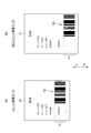
図3(A)は、レシート画像データ50を所定の座標系に展開した様子を模式的に示す図である。
図3(A)に示すレシート画像データ50において、長手方向は、感熱ロール紙の長手方向に対応しており、当該レシート画像データ50に基づいて感熱ロール紙に画像が記録される際は、図中矢印Y1に示す方向と対応する方向(搬送方向)に感熱ロール紙が搬送されつつ、画像が記録されるものとする。
また、本実施形態において、バーコードは、一方向に延びる複数のバーによって、黒と空白の2色の領域を形成し、識別情報を示すタイプのものであるものとする。この種のバーコードとしては、例えば、JAN、EAN、CODE39、CODE93、CODE128、ITF、NW−7等が存在する。特に、本実施形態では、バーコードの各バーが、レシートの長手方向(搬送方向)に延在するような態様で、バーコードの画像がレシートに記録されるものとする。
また、以下の説明において、レシート画像データ50は、白黒2値のビットマップデータであるものとする。
FIG. 3A is a diagram schematically showing a state in which the
In the
Further, in the present embodiment, the barcode is of a type in which a black and blank two-color region is formed by a plurality of bars extending in one direction and indicates identification information. Examples of this type of barcode include JAN, EAN, CODE39, CODE93, CODE128, ITF, and NW-7. In particular, in the present embodiment, the barcode image is recorded on the receipt in such a manner that each bar of the barcode extends in the longitudinal direction (conveying direction) of the receipt.
In the following description, the
ステップSA2において、バーコード判別部21aは、レシート画像データ50を、所定の座標系に展開する。これにより、レシート画像データ50の各画素の座標は、座標系において原点として規定された位置からの相対的な位置によって一意に定義される。
次いで、バーコード判別部21aは、レシート画像データ50を分析することによって、長手方向に延び、かつ、長さが一定の範囲にある直線の画像が、平行して所定の数以上並んだ画像に係る画像データ(バーコードデータ)が存在するか否かを判別する。所定の数とは、バーコードとして成立するために必要なバーの数の最小値のことであり、バーコードの規格に応じて適宜定められる。
ステップSA3において、バーコード判別部21aは、レシート画像データ50内に上記態様の画像データが存在する場合、レシート画像データ50にバーコードデータが含まれていると判別し(ステップSA3:YES)、一方、上記態様の画像データが存在しない場合、レシート画像データ50にバーコードデータが含まれていないと判別する(ステップSA3:NO)。
なお、レシート画像データ50にバーコードデータが含まれているかを判別する際の方法は、上述した方法に限らず、パターンマッチングを利用した方法等、既存の方法を広く適用することが可能である。
In step SA2, the
Next, the bar
In step SA3, the
Note that the method for determining whether the
ステップSA3において、レシート画像データ50にバーコードデータが含まれていないと判別した場合(ステップSA3:NO)、制御コマンド生成部21bは、POSアプリケーション実行部20から入力された画像情報データに基づいて、記録制御コマンドを生成する(ステップSA4)。当該記録制御コマンドには、レシート画像データ50、及び、レシート画像データ50に基づいて画像の記録を実行させるコマンドが含まれている。次いで、記録制御部21cは、ステップSA4で生成された記録制御コマンドをプリンター12に出力する。プリンター12のプリンター側制御部30は、入力された記録制御コマンドに基づいて、プリントエンジン33を制御して、感熱ロール紙への画像の記録や、画像の記録に伴う搬送、感熱ロール紙の切断等、レシートの発行に係る各種処理を実行して、レシートを発行する。
When it is determined in step SA3 that the
一方、ステップSA3において、レシート画像データ50にバーコードデータが含まれていると判別した場合(ステップSA3:YES)、制御コマンド生成部21bは、レシート画像データ50においてバーコードデータが長手方向に延在する範囲に、他の画像に係る画像データの少なくとも一部が含まれているか否かを判別する(ステップSA6)。ここで、他の画像は、1又は複数の黒値のドットの組み合わせによって構成された画像であり、例えば、図3(A)の例では、レシート画像データ50において、バーコードデータBDが長手方向に延在する範囲である範囲H1に、「THANKS」を示す画像(他の画像)の少なくとも一部が含まれている状態であるため、ステップSA6において、制御コマンド生成部21bは、バーコードデータが長手方向に延在する範囲に、他の画像の少なくとも一部が含まれていると判別する。
上述したように、プリンター12は、ラインサーマルヘッド25によって感熱ロール紙に画像を記録する。従って、バーコードデータが長手方向に延在する範囲に他の画像の少なくとも一部が含まれている場合、バーコードの画像と、当該他の画像とについて、長手方向に延在する範囲で重なっている部分における短手方向に延びる同一直線上の各画素については、ラインサーマルヘッド25の一列の発熱素子によって同時に記録されることとなる。
On the other hand, if it is determined in step SA3 that the
As described above, the printer 12 records an image on the thermal roll paper using the line
ステップSA6において、レシート画像データ50において、バーコードデータが長手方向に延在する範囲に、他の画像に係る画像データの少なくとも一部が含まれていない場合(ステップSA6:NO)、制御コマンド生成部21bは、処理手順をステップSA7へ移行する。
一方、レシート画像データ50において、バーコードデータが長手方向に延在する範囲に、他の画像に係る画像データの少なくとも一部が含まれている場合(ステップSA6:YES)、制御コマンド生成部21bは、以下の手順で、レシートに記録すべき画像のレイアウトを変更し、変更後のレイアウトに準じて、レシートに記録すべき画像の画像データ(以下、「加工レシート画像データ51」という。)を生成する(ステップSA8)
In step SA6, if the
On the other hand, in the
図3(B)は、図3(A)のレシート画像データ50に基づいて生成された加工レシート画像データ51を示す図である。
すなわち、制御コマンド生成部21bは、レシートに記録すべき画像について、バーコードと他の画像とが長手方向に延在する範囲で重なる部分がないようにそのレイアウトを変更し、図3(B)に示すように、変更後のレイアウトに準じて、バーコードデータと、他の画像に係る画像データとが、長手方向において重なる部分がないように、予め定められた所定の規則に準じて、レシート画像データ50におけるバーコードデータの領域を変移することにより、加工レシート画像データ51を生成する。本実施形態では、所定の規則として、バーコードデータの領域を、他の画像の画像データと重なった部分が無いように、搬送方向と逆方向に対応する方向(図3中矢印Y2に示す方向)に変移する旨が定められており、当該規則に準じた画像処理がなされるよう、当該規則が適切な態様でプログラム上に定義されている。
FIG. 3B is a diagram showing processed
That is, the control
ステップSA7において、制御コマンド生成部21bは、レシート画像データ50(ステップSA8において加工レシート画像データ51を生成した場合は、加工レシート画像データ51)に基づいて、バーコード制御コマンドを生成する。
以下、ステップSA7の処理について詳述する。なお、以下のステップSA7の説明では、説明の便宜のため、レシート画像データ50と、加工レシート画像データ51を区別せずに、レシート画像データ50と表現する。
バーコードデータは、所定の規格に準拠したバーコードを示す画像データである。そして、バーコードは、数値を含む文字列からなる識別情報を示す識別コードである。
ステップSA7において、制御コマンド生成部21bは、所定の座標系に展開したバーコードデータにおけるバーの画像の態様を分析し、既存のアルゴリズムを用いて、当該バーコードデータに係るバーコードが示す識別情報を取得する。
次いで、制御コマンド生成部21bは、プリンター12のコマンド仕様に準じて、バーコードが示す識別情報を指定し、指定した識別情報に基づいてバーコードの画像を記録させるコマンド群であるバーコード制御コマンドを生成する。このバーコード制御コマンドには、バーコードが示す識別情報を指定するコマンドのほか、バーコードを記録する際のサイズを指定するコマンド、バーコードを記録する際の位置を指定するコマンド等、プリンター12が識別情報に基づいてバーコードの画像を記録するにあたって必要なコマンドが過不足なく含まれて構成されたコマンド群である。
プリンター12のファームウェアには、バーコード制御コマンドに基づいて、識別情報を、プリンター12の記録解像度を反映したバーコードの画像データに変換し、変換した画像データに基づいてバーコードの画像を記録する機能を有するプログラムが実装されている。従って、ホストコンピューター10からプリンター12に対して、バーコードデータの代わりに、当該バーコードデータに係るバーコード制御コマンドを出力することにより、プリンター12に正常にバーコードの画像を記録させることが可能である。
In step SA7, the
Hereinafter, the process of step SA7 will be described in detail. In the following description of Step SA7, for convenience of explanation, the
The barcode data is image data indicating a barcode that conforms to a predetermined standard. The bar code is an identification code indicating identification information composed of a character string including a numerical value.
In step SA7, the control
Next, the control
Based on the barcode control command, the identification information is converted into barcode image data reflecting the recording resolution of the printer 12 and the barcode image is recorded on the firmware of the printer 12 based on the converted image data. A program having a function is implemented. Therefore, by outputting a barcode control command related to the barcode data instead of barcode data from the
さて、ステップSA7に続くステップSA9において、制御コマンド生成部21bは、ステップSA7において生成したバーコード制御コマンドを含む記録制御コマンドを生成する。
In step SA9 following step SA7, the control
図4は、ステップSA9の処理を説明するための図であり、(A)は、加工レシート画像データ51の一例を示し、(B)は、(A)の加工レシート画像データ51に基づいて生成される記録制御コマンドの内容を模式的に示す図である。図4(B)では、記録制御コマンドに含まれるコマンドを単純化して表現している。
図4(A)に示すように、加工レシート画像データ51は、大別して、バーコードデータ以外の領域A1と、バーコードデータに対応する領域A2とに分かれている。
ステップSA9において、まず、制御コマンド生成部21bは、加工レシート画像データ51から領域A1を切り出して、当該領域A1に対応する画像データ(以下、「抽出画像データ」という。)を生成する。次いで、制御コマンド生成部21bは、当該抽出画像データを含み、当該抽出画像データに基づいて画像を記録させるコマンド(以下、「抽出画像記録指示コマンド」という)を生成する。プリンター12は、当該抽出画像記録指示コマンドに基づいて画像を記録することにより、加工レシート画像データ51の領域A1に対応する画像を感熱ロール紙に記録することが可能である。
さらに、制御コマンド生成部21bは、図4(B)に示すように、抽出画像記録指示コマンドの後に、ステップSA7で生成したバーコード制御コマンドを付加する。上述したように、プリンター12は、バーコード制御コマンドに基づいて、自身の記録解像度を反映したバーコードの画像を記録することが可能である。なお、図4(B)では、省略しているが、記録制御コマンドには、抽出画像記録指示コマンド、及び、バーコード制御コマンドのほかに、レシートにおいて、抽出画像記録指示コマンドに基づいて記録される画像と、バーコード制御コマンドに基づいて記録されるバーコードの画像との位置の調整を行うための所定のコマンドが含まれている。
4A and 4B are diagrams for explaining the process of step SA9. FIG. 4A shows an example of the processed
As shown in FIG. 4A, the processed
In step SA9, first, the
Further, as shown in FIG. 4B, the control
さらに、制御コマンド生成部21bは、当該バーコード制御コマンドに基づいてバーコードの画像を記録する際に、記録速度を所定の速度に低下させて記録を実行することを指示するコマンドである記録方法指示コマンドを、バーコード制御コマンドに付加する。
ここで、プリンター12では、記録に伴って発生する振動の影響、その他の記録に係る構造上の特徴に起因して、遅い記録速度で画像を記録した場合の方が、速い記録速度で画像を記録する場合と比較して、高い精度で画像を記録することができる。
そして、バーコード制御コマンドに記録方法指示コマンドに付加することにより、バーコードの画像については、記録速度を落として記録さえることとなり、バーコードの画像を高い精度で記録することが可能となる。特に、本実施形態では、領域A1に対応する部分は、通常の記録速度で記録され、バーコードデータに係るバーコードの画像のみが遅い記録速度で記録されることとなるため、バーコードの画像の精度を維持しつつ、記録に要する時間の長時間化を抑制することが可能である。
さらに、上述したように、本実施形態は、レシートに記録すべき画像において、バーコードと、他の画像とが長手方向において重なっている場合は、重ならないようにレイアウトが変更され、変更後のレイアウトに準じて記録がなされるように記録制御コマンドが生成される。従って、プリンター12がバーコードの画像を記録する場合、当該バーコードの画像は、独立して記録されることとなり、他の画像と同時並行的に記録されることがない。このため、バーコードの画像のみを遅い速度で記録する、ということが可能となり、バーコードの画像以外の画像が、同一の印刷品質で(同一の記録速度で)記録されることとなり、レシートにおける印刷品質のムラを抑制でき、全体的な印刷品質の向上を図ることが可能となる。
Furthermore, the control
Here, in the printer 12, the image is recorded at a higher recording speed when the image is recorded at a slower recording speed due to the influence of vibrations generated by the recording and other structural features related to the recording. Compared to the case of recording, an image can be recorded with higher accuracy.
By adding the recording method instruction command to the barcode control command, the barcode image can be recorded at a low recording speed, and the barcode image can be recorded with high accuracy. In particular, in the present embodiment, the portion corresponding to the area A1 is recorded at the normal recording speed, and only the barcode image related to the barcode data is recorded at the slow recording speed. It is possible to suppress an increase in the time required for recording while maintaining the accuracy of recording.
Furthermore, as described above, in the present embodiment, in the image to be recorded on the receipt, when the barcode and the other image overlap in the longitudinal direction, the layout is changed so as not to overlap, and the post-change A recording control command is generated so that recording is performed according to the layout. Therefore, when the printer 12 records a barcode image, the barcode image is recorded independently, and is not recorded simultaneously with other images. Therefore, it is possible to record only the barcode image at a low speed, and images other than the barcode image are recorded with the same print quality (at the same recording speed). Unevenness in print quality can be suppressed, and overall print quality can be improved.
さて、前掲図2に戻り、ステップSA10において、プリンタードライバー実行部21の記録制御部21cは、ステップSA9において制御コマンド生成部21bにより生成された記録制御コマンドを、プリンター12に出力する(ステップSA10)。
記録制御コマンドが入力されたプリンター12のプリンター側制御部30は、記録制御コマンドに含まれる抽出画像記録指示コマンドに基づいて、レシート画像データ50のうち、バーコードデータ以外の部分に係る画像について、画像を記録する。さらに、プリンター側制御部30のバーコード制御コマンド実行部30aは、記録制御コマンドに含まれるバーコード制御コマンド、及び、バーコード制御コマンドに付加された記録方法指示コマンドに基づいて、記録速度を落とした上で、バーコードの画像を記録する。詳述すると、バーコード制御コマンド実行部30aは、ファームウェアの機能により、バーコード制御コマンドを解析し、バーコード制御コマンドに含まれる識別情報をバーコードデータに変換する。当該変換に際し、バーコード制御コマンド実行部30aは、変換後のバーコードデータが、ラインサーマルヘッド25の記録解像度に応じた解像度となり、かつ、画像バッファーに展開可能な形式の画像データとなるようにする。次いで、バーコード制御コマンド実行部30aは、変換したバーコードデータを画像バッファーに展開し、展開したバーコードデータに基づいて、プリントエンジン33を制御して、バーコードの画像を記録する。このように、バーコード制御コマンド実行部30aは、ファームウェアの機能により、バーコードの記録に際し、識別情報を、プリンター12の記録解像度に対応した画像データに変換して、当該画像データに基づいて記録する。
ここで、従来の記録システム1では、バーコードの記録に際し、POSアプリケーション実行部20からプリンタードライバー実行部21に対して、画像データ(例えば、ビットマップデータ)たるバーコードデータが出力された場合、ホストコンピューター10は、プリンター12に対して、当該バーコードデータをそのまま出力していた。この場合、POSアプリケーションの仕様、その他の要因により、ホストコンピューター10からプリンター12に出力されるバーコードデータの解像度が、プリンター12の記録解像度と相違することがあった。この場合、プリンター12側で、解像度の相違に応じて、バーコードデータに対して解像度を調整する加工を行い、加工後のバーコードデータに基づいて、バーコードの画像を記録していた。この場合、データの加工の過程において、バーコードデータの精度が低下し、これに起因してバーコードの画像の精度が低下する可能性があった。しかしながら、本実施形態では、ホストコンピューター10からプリンター12に対して、バーコードデータそのものが出力されるのではなく、バーコードの識別情報が出力され、プリンター12側で、プリンター12の記録解像度に応じて、当該識別情報をバーコードデータに変換して、変換後のバーコードデータに基づいて画像を記録する構成のため、従来のような解像度のミスマッチに起因したバーコードの画像の精度の低下という事態が起こり得ない。さらに、バーコードデータそのものを出力する場合と比較して、バーコード制御コマンドは、データ量が小さいため、プリンター12とホストコンピューター10との間における通信トラフィックの低減を図ることができ、これに基づいた処理効率の向上を実現可能である。
Now, referring back to FIG. 2, in step SA10, the
Based on the extracted image recording instruction command included in the recording control command, the printer-
Here, in the
以上説明したように、本実施形態に係るホストコンピューター10は、プリンター12によってレシートに記録させる画像の画像データに、バーコードの画像に係るバーコードデータが含まれているか否かを判別するバーコード判別部21aと、このバーコード判別部21aによりバーコードデータが含まれていると判別された場合、バーコードの識別情報を指定し、プリンター12に識別情報をバーコードの画像に変換させて記録させるバーコード制御コマンドを生成すると共に、生成した前記バーコード制御コマンドを含み、プリンター12によって感熱ロール紙に画像を記録させる記録制御コマンドを生成する制御コマンド生成部21bと、制御コマンド生成部21bにより生成された記録制御コマンドをプリンター12に出力することにより、プリンター12に記録させる画像のうち少なくともバーコードの画像については、バーコード制御コマンドに基づいて記録させる記録制御部21cと、を備えている。
これによれば、レシートを構成する感熱ロール紙への記録に際し、バーコードに係る画像に関しては、ホストコンピューター10からプリンター12に対して、当該画像の画像データが出力されるのではなく、当該バーコードを示す識別情報を指定して、当該識別情報を当該バーコードに係る画像に変換させて記録させるためのバーコード制御コマンドが出力される。この場合、プリンター12は、バーコードに係る画像の記録に際し、自身に実装された機能により、自身の記録解像度を反映して、バーコード制御コマンドに含まれる識別情報を変換して、当該画像を記録することとなるため、ホストコンピューター10からプリンター12に対してバーコードの画像データを出力したときの解像度のミスマッチに起因した精度の低下が起こり得ず、高い精度でのバーコードの画像の記録が可能となる。
また、バーコードの画像データは、ビットマップデータ等、画素ごとの描画情報を保持するデータであるため、識別情報を指定する情報を含んで構成されるバーコード制御コマンドと比較して、データ量が多い。そして、上記構成によれば、画像の記録に際し、バーコードの画像については、制御装置から記録装置に対して、画像データではなく、バーコード制御コマンドが出力されることとなるため、これら装置間の通信トラフィックの低減、及び、処理に要する時間の短縮化を実現可能である。
As described above, the
According to this, when recording on the heat-sensitive roll paper constituting the receipt, the image data of the bar code is not output from the
Further, since the barcode image data is data that holds drawing information for each pixel, such as bitmap data, the amount of data compared to a barcode control command configured to include information specifying identification information There are many. According to the above configuration, when recording an image, a barcode control command, not image data, is output from the control device to the recording device for the barcode image. It is possible to achieve a reduction in communication traffic and a reduction in processing time.
また、本実施形態では、制御コマンド生成部21bは、バーコード制御コマンドに基づいてバーコードの画像を記録する際に、印刷品質が向上する方法で記録を実行することを指示する記録方法指示コマンドを、バーコード制御コマンドに付加する。
より具体的には、制御コマンド生成部21bは、バーコードの画像を記録する際に、記録速度を落として画像を記録させることを指示する記録方法指示コマンドを、バーコード制御コマンドに付加する。
これによれば、バーコードの画像は、記録速度を低下させて記録されることとなるため、バーコードの画像をより高い精度で記録することが可能となる。特に、上記構成によれば、バーコードの画像だけが、記録速度を低下させて記録されることとなるため、記録に要する時間の長期化を抑制しつつ、バーコードの画像の高い精度での記録を実現可能である。
なお、上記のことは、プリンター12によって感熱ロール紙に記録する際に、ホストコンピューター10からプリンター12に対して記録すべき画像全体の画像データが出力され、プリンター12が、画像データに基づいて、バーコードの画像を含む画像全体を連続一体的に記録するのではなく、上記構成のように、レシートに記録すべき画像のうち、バーコードに係る画像については、バーコード制御コマンドに基づいて記録させる構成だからこそ実現可能である。
Further, in the present embodiment, the control
More specifically, when recording a barcode image, the control
According to this, since the barcode image is recorded at a reduced recording speed, the barcode image can be recorded with higher accuracy. In particular, according to the above configuration, only the barcode image is recorded at a reduced recording speed, so that the time required for recording is suppressed and the barcode image is highly accurate. Recording is feasible.
Note that, when recording on the thermal roll paper by the printer 12, the image data of the entire image to be recorded is output from the
また、本実施形態では、制御コマンド生成部21bは、プリンター12によってレシートに記録させる画像のレイアウトが、記録に際し、バーコードの画像の記録と、その他の画像の記録との少なくとも一部が並行して行われるようなレイアウトとなっている場合は、プリンター12によってレシートに記録させる画像のレイアウトを、バーコードの画像の記録が独立して行われるようなレイアウトへと変更し、変更後のレイアウトに準じて、バーコード制御コマンドを含んで構成された記録制御コマンドを生成する。
これによれば、レシートに記録すべき画像のうち、バーコードの画像について、的確に、記録の精度を向上させることができる。特に、バーコードの画像以外の画像については、均質な印刷品質で記録されることとなるため、レシートに記録される画像の全体的な印刷品質の向上を図ることが可能となる。
In the present embodiment, the control
According to this, among the images to be recorded on the receipt, it is possible to accurately improve the recording accuracy for the barcode image. In particular, since images other than the barcode image are recorded with a uniform print quality, it is possible to improve the overall print quality of the image recorded on the receipt.
なお、上述した実施の形態は、あくまでも本発明の一態様を示すものであり、本発明の範囲内で任意に変形および応用が可能である。
例えば、上述した実施形態では、プリンター12は、サーマル式であったが、記録形式はこれに限らず、インクジェットプリンター、ドットインパクトプリンター、レーザープリンター、熱昇華型プリンター等であってもよい。すなわち、本発明は、記録媒体にバーコードを記録する可能性のある記録装置、当該記録装置を制御する制御装置、当該記録装置と当該制御装置とを備えるシステムに広く適用可能である。
また例えば、図1に示す各機能ブロックはハードウェアとソフトウェアの協働により任意に実現可能であり、特定のハードウェア構成を示唆するものではない。
また例えば、装置の外部の記憶媒体に記憶させたプログラムを実行することにより、制御部15や、プリンター側制御部30の各機能を実現するようにしてもよく、また、図で示した各フローチャートの各ステップを実行するようにしてもよい。
The above-described embodiment is merely an aspect of the present invention, and can be arbitrarily modified and applied within the scope of the present invention.
For example, in the above-described embodiment, the printer 12 is a thermal type, but the recording format is not limited to this, and may be an inkjet printer, a dot impact printer, a laser printer, a thermal sublimation printer, or the like. That is, the present invention can be widely applied to a recording apparatus that may record a barcode on a recording medium, a control apparatus that controls the recording apparatus, and a system that includes the recording apparatus and the control apparatus.
Further, for example, each functional block shown in FIG. 1 can be arbitrarily realized by cooperation of hardware and software, and does not suggest a specific hardware configuration.
Further, for example, each function of the
1…記録システム、10…ホストコンピューター(制御装置)、12…プリンター(記録装置)、15…制御部、21…プリンタードライバー実行部、21a…バーコード判別部、21b…制御コマンド生成部、21c…記録制御部、30…プリンター側制御部、30a…バーコード制御コマンド実行部。
DESCRIPTION OF
Claims (9)
前記バーコード判別部により前記バーコードデータが含まれていると判別された場合、前記バーコードの識別情報を指定し、前記識別情報を記録用のバーコードの画像に変換させて前記記録装置によって前記記録用のバーコードの画像を記録させるバーコード制御コマンドを生成すると共に、生成した前記バーコード制御コマンドを含み、前記記録装置によって前記記録媒体に画像を記録させる記録制御コマンドを生成する制御コマンド生成部と、
前記制御コマンド生成部により生成された前記記録制御コマンドを前記記録装置に出力することにより、前記記録装置によって記録させる画像のうち少なくとも前記バーコード
の画像については、前記バーコード制御コマンドに基づいて記録させる記録制御部と、
を備え、
前記制御コマンド生成部は、前記記録装置によって前記記録媒体に記録させる画像のレイアウトが、記録に際し、前記バーコードの画像の記録と、その他の画像の記録との少なくとも一部が並行して行われるようなレイアウトとなっている場合は、前記記録装置によって前記記録媒体に記録させる画像のレイアウトを、前記バーコードの画像の記録が独立して行われるレイアウトへと変更し、変更後のレイアウトに準じて、前記バーコード制御コマンドを含んで構成された前記記録制御コマンドを生成することを特徴とする制御装置。 A barcode discriminating unit for discriminating whether or not the image data of the image to be recorded on the recording medium by the recording device includes barcode data related to the barcode image;
When the barcode determination unit determines that the barcode data is included, the barcode identification information is designated, the identification information is converted into a barcode image for recording, and the recording device A control command for generating a barcode control command for recording an image of the barcode for recording, and for generating a recording control command including the generated barcode control command and for recording an image on the recording medium by the recording device A generator,
By outputting the recording control command generated by the control command generating unit to the recording device, at least the barcode image among the images to be recorded by the recording device is recorded based on the barcode control command. A recording control unit
Equipped with a,
In the control command generation unit, at the time of recording the image layout to be recorded on the recording medium by the recording device, at least a part of the recording of the barcode image and the recording of the other image is performed in parallel. If the layout is such that the layout of the image to be recorded on the recording medium by the recording device is changed to a layout in which the recording of the barcode image is performed independently, according to the layout after the change Te, the control apparatus characterized that you generate the recording control command configured to include the bar code control commands.
前記バーコード制御コマンドに基づいて前記記録用のバーコードの画像を記録する際に、印刷品質が向上する方法で記録を実行することを指示する記録方法指示コマンドを、前記バーコード制御コマンドに付加することを特徴とする請求項1に記載の制御装置。 The control command generator is
When recording an image of the recording barcode based on the barcode control command, a recording method instruction command is added to the barcode control command to instruct execution of recording in a manner that improves print quality. The control device according to claim 1, wherein:
前記バーコードデータが含まれていると判別した場合、前記バーコードの識別情報を指定し、前記識別情報を記録用のバーコードの画像に変換させて前記記録装置によって前記記録用のバーコードの画像を記録させるバーコード制御コマンドを生成すると共に、生成した前記バーコード制御コマンドを含み、前記記録装置によって前記記録媒体に画像を記録させる記録制御コマンドを生成し、
生成した前記記録制御コマンドを前記記録装置に出力することにより、前記記録装置に記録させる画像のうち少なくとも前記バーコードの画像については、前記バーコード制御コマンドに基づいて記録させ、
前記記録制御コマンドの生成は、前記記録装置によって前記記録媒体に記録させる画像のレイアウトが、記録に際し、前記バーコードの画像の記録と、その他の画像の記録との少なくとも一部が並行して行われるようなレイアウトとなっている場合は、前記記録装置によって前記記録媒体に記録させる画像のレイアウトを、前記バーコードの画像の記録が独立して行われるレイアウトへと変更し、変更後のレイアウトに準じて、前記バーコード制御コマンドを含んで構成された前記記録制御コマンドを生成することを特徴とする制御装置の制御方法。 Determining whether the image data of the image to be recorded on the recording medium by the recording device includes the barcode data relating to the image of the barcode;
When it is determined that the barcode data is included, the barcode identification information is designated, the identification information is converted into a recording barcode image, and the recording barcode is recorded by the recording device. Generating a barcode control command for recording an image, including the generated barcode control command, generating a recording control command for recording an image on the recording medium by the recording device;
By outputting the generated recording control command to the recording device, at least the barcode image among the images to be recorded on the recording device is recorded based on the barcode control command,
The recording control command is generated when the image layout to be recorded on the recording medium by the recording device is recorded, and at least a part of the recording of the barcode image and the recording of the other image is performed in parallel. The layout of the image to be recorded on the recording medium by the recording device is changed to a layout in which the recording of the barcode image is performed independently, and the changed layout is obtained. analogously, the control method of the control device, characterized that you generate the recording control command configured to include the bar code control commands.
前記バーコード制御コマンドに基づいて前記記録用のバーコードの画像を記録する際に、印刷品質が向上する方法で記録を実行することを指示する記録方法指示コマンドを、前記バーコード制御コマンドに付加することを特徴とする請求項4に記載の制御装置の制御方法。 The recording control command is generated by
When recording an image of the recording barcode based on the barcode control command, a recording method instruction command is added to the barcode control command to instruct execution of recording in a manner that improves print quality. The control method of the control apparatus according to claim 4 , wherein:
記録装置によって記録媒体に記録させる画像の画像データに、バーコードの画像に係るバーコードデータが含まれているか否かを判別するバーコード判別部と、
前記バーコード判別部により前記バーコードデータが含まれていると判別された場合、
前記バーコードの識別情報を指定し、前記識別情報を記録用のバーコードの画像に変換させて前記記録装置によって前記記録用のバーコードの画像を記録させるバーコード制御コマンドを生成すると共に、生成した前記バーコード制御コマンドを含み、前記記録装置によって前記記録媒体に画像を記録させる記録制御コマンドを生成する制御コマンド生成部と、
前記制御コマンド生成部により生成された前記記録制御コマンドを前記記録装置に出力することにより、前記記録装置に記録させる画像のうち少なくとも前記バーコードの画像については、前記バーコード制御コマンドに基づいて記録させる記録制御部と、
として機能させ、
前記制御コマンド生成部は、前記記録装置によって前記記録媒体に記録させる画像のレイアウトが、記録に際し、前記バーコードの画像の記録と、その他の画像の記録との少なくとも一部が並行して行われるようなレイアウトとなっている場合は、前記記録装置によって前記記録媒体に記録させる画像のレイアウトを、前記バーコードの画像の記録が独立して行われるレイアウトへと変更し、変更後のレイアウトに準じて、前記バーコード制御コマンドを含んで構成された前記記録制御コマンドを生成する
ことを特徴とするプログラム。 The control unit
A barcode discriminating unit for discriminating whether or not the image data of the image to be recorded on the recording medium by the recording device includes barcode data related to the barcode image;
When it is determined that the barcode data is included by the barcode determination unit,
Designates and generates a barcode control command for specifying the barcode identification information, converting the identification information into a recording barcode image, and recording the recording barcode image by the recording device A control command generation unit that generates a recording control command that includes the barcode control command and causes the recording apparatus to record an image on the recording medium;
By outputting the recording control command generated by the control command generation unit to the recording device, at least the barcode image among the images to be recorded by the recording device is recorded based on the barcode control command. A recording control unit
Function as
In the control command generation unit, at the time of recording the image layout to be recorded on the recording medium by the recording device, at least a part of the recording of the barcode image and the recording of the other image is performed in parallel. If the layout is such that the layout of the image to be recorded on the recording medium by the recording device is changed to a layout in which the recording of the barcode image is performed independently, according to the layout after the change To generate the recording control command including the barcode control command.
Program, characterized in that.
前記バーコード制御コマンドに基づいて前記記録用のバーコードの画像を記録する際に、印刷品質が向上する方法で記録を実行することを指示する記録方法指示コマンドを、前記バーコード制御コマンドに付加することを特徴とする請求項7に記載のプログラム。 The control command generator is
When recording an image of the recording barcode based on the barcode control command, a recording method instruction command is added to the barcode control command to instruct execution of recording in a manner that improves print quality. The program according to claim 7 .
Priority Applications (1)
| Application Number | Priority Date | Filing Date | Title |
|---|---|---|---|
| JP2011191462A JP5754307B2 (en) | 2011-09-02 | 2011-09-02 | CONTROL DEVICE, CONTROL DEVICE CONTROL METHOD, AND PROGRAM |
Applications Claiming Priority (1)
| Application Number | Priority Date | Filing Date | Title |
|---|---|---|---|
| JP2011191462A JP5754307B2 (en) | 2011-09-02 | 2011-09-02 | CONTROL DEVICE, CONTROL DEVICE CONTROL METHOD, AND PROGRAM |
Publications (3)
| Publication Number | Publication Date |
|---|---|
| JP2013054492A JP2013054492A (en) | 2013-03-21 |
| JP2013054492A5 JP2013054492A5 (en) | 2014-08-21 |
| JP5754307B2 true JP5754307B2 (en) | 2015-07-29 |
Family
ID=48131433
Family Applications (1)
| Application Number | Title | Priority Date | Filing Date |
|---|---|---|---|
| JP2011191462A Expired - Fee Related JP5754307B2 (en) | 2011-09-02 | 2011-09-02 | CONTROL DEVICE, CONTROL DEVICE CONTROL METHOD, AND PROGRAM |
Country Status (1)
| Country | Link |
|---|---|
| JP (1) | JP5754307B2 (en) |
Families Citing this family (2)
| Publication number | Priority date | Publication date | Assignee | Title |
|---|---|---|---|---|
| JP6507809B2 (en) * | 2015-04-10 | 2019-05-08 | 富士ゼロックス株式会社 | Printing instruction device, printing system and program |
| JP6615278B2 (en) * | 2018-07-04 | 2019-12-04 | 株式会社Screenホールディングス | Printing device |
Family Cites Families (5)
| Publication number | Priority date | Publication date | Assignee | Title |
|---|---|---|---|---|
| JPH06284282A (en) * | 1993-03-25 | 1994-10-07 | Toshiba Corp | Image forming device |
| JPH11221946A (en) * | 1998-02-06 | 1999-08-17 | Casio Electronics Co Ltd | Print system and method |
| JP2006262078A (en) * | 2005-03-17 | 2006-09-28 | Ricoh Co Ltd | Image processor |
| JP4661580B2 (en) * | 2005-12-22 | 2011-03-30 | 富士ゼロックス株式会社 | Image processing apparatus and program |
| JP2011056874A (en) * | 2009-09-11 | 2011-03-24 | Seiko Epson Corp | Line printer and control method therefor |
-
2011
- 2011-09-02 JP JP2011191462A patent/JP5754307B2/en not_active Expired - Fee Related
Also Published As
| Publication number | Publication date |
|---|---|
| JP2013054492A (en) | 2013-03-21 |
Similar Documents
| Publication | Publication Date | Title |
|---|---|---|
| US8867087B2 (en) | Printing apparatus, printing system, and printing control method for printing a watermark on a receipt along with print data sent from a host apparatus | |
| JP5909871B2 (en) | Recording device | |
| JP5810609B2 (en) | RECORDING DEVICE, RECORDING DEVICE CONTROL METHOD, AND PROGRAM | |
| US9141892B2 (en) | Adjusting one side print data to avoid overlap with the other side print data in two-sided printing | |
| US9001171B2 (en) | Double-sided receipt printing method and double-sided receipt printer | |
| KR101429850B1 (en) | Recording device and control method of a recording device | |
| JP5754307B2 (en) | CONTROL DEVICE, CONTROL DEVICE CONTROL METHOD, AND PROGRAM | |
| JP5532848B2 (en) | Recording control apparatus, control method, and program | |
| US10046577B2 (en) | Printing device, printing system, and control method of a printing device | |
| JP2012113608A (en) | Control device, recording system, control method of control device, and program | |
| JP5862045B2 (en) | RECORDING DEVICE, RECORDING DEVICE CONTROL METHOD, AND PROGRAM | |
| US8724148B2 (en) | Recording device that can connect to a control device, control method for a recording device that can connect to a control device, and storage medium that stores a program for controlling parts of a recording device that can connect to a control device | |
| JP2011173278A (en) | Bar code printer | |
| JP2012123704A (en) | Control apparatus, control method of control apparatus, and program | |
| US20190210377A1 (en) | Printer and printer system | |
| JP5760705B2 (en) | RECORDING DEVICE, RECORDING DEVICE CONTROL METHOD, AND PROGRAM | |
| JP5891610B2 (en) | RECORDING DEVICE, RECORDING DEVICE CONTROL METHOD, AND IMAGE CORRECTION PROGRAM | |
| JP2013257805A (en) | Control device, control method of control device, and program | |
| JP6032334B2 (en) | Control device and recording system | |
| JP2014054846A (en) | Control device, control method for control device, and program | |
| JP5906606B2 (en) | Control device, recording device, control method of control device, and program | |
| JP2011084027A (en) | Recording device, control method of recording device, and program | |
| JP2012174094A (en) | Electronic apparatus, control method for electronic apparatus, and program | |
| JP2012101391A (en) | Recording apparatus, method for controlling the same, and program | |
| JP2013055389A (en) | Controller, recorder, method of controlling controller, and program |
Legal Events
| Date | Code | Title | Description |
|---|---|---|---|
| A521 | Request for written amendment filed |
Free format text: JAPANESE INTERMEDIATE CODE: A523 Effective date: 20140704 |
|
| A621 | Written request for application examination |
Free format text: JAPANESE INTERMEDIATE CODE: A621 Effective date: 20140704 |
|
| RD04 | Notification of resignation of power of attorney |
Free format text: JAPANESE INTERMEDIATE CODE: A7424 Effective date: 20150107 |
|
| A977 | Report on retrieval |
Free format text: JAPANESE INTERMEDIATE CODE: A971007 Effective date: 20150123 |
|
| A131 | Notification of reasons for refusal |
Free format text: JAPANESE INTERMEDIATE CODE: A131 Effective date: 20150217 |
|
| A521 | Request for written amendment filed |
Free format text: JAPANESE INTERMEDIATE CODE: A523 Effective date: 20150227 |
|
| TRDD | Decision of grant or rejection written | ||
| A01 | Written decision to grant a patent or to grant a registration (utility model) |
Free format text: JAPANESE INTERMEDIATE CODE: A01 Effective date: 20150428 |
|
| A61 | First payment of annual fees (during grant procedure) |
Free format text: JAPANESE INTERMEDIATE CODE: A61 Effective date: 20150511 |
|
| R150 | Certificate of patent or registration of utility model |
Ref document number: 5754307 Country of ref document: JP Free format text: JAPANESE INTERMEDIATE CODE: R150 |
|
| S531 | Written request for registration of change of domicile |
Free format text: JAPANESE INTERMEDIATE CODE: R313531 |
|
| R350 | Written notification of registration of transfer |
Free format text: JAPANESE INTERMEDIATE CODE: R350 |
|
| LAPS | Cancellation because of no payment of annual fees |