JP5891010B2 - Thin plate workpiece grinding method and double-head surface grinding machine - Google Patents
Thin plate workpiece grinding method and double-head surface grinding machine Download PDFInfo
- Publication number
- JP5891010B2 JP5891010B2 JP2011243137A JP2011243137A JP5891010B2 JP 5891010 B2 JP5891010 B2 JP 5891010B2 JP 2011243137 A JP2011243137 A JP 2011243137A JP 2011243137 A JP2011243137 A JP 2011243137A JP 5891010 B2 JP5891010 B2 JP 5891010B2
- Authority
- JP
- Japan
- Prior art keywords
- grinding
- workpiece
- difference
- accuracy
- reference position
- Prior art date
- Legal status (The legal status is an assumption and is not a legal conclusion. Google has not performed a legal analysis and makes no representation as to the accuracy of the status listed.)
- Active
Links
- 238000000227 grinding Methods 0.000 title claims description 496
- 238000000034 method Methods 0.000 title claims description 20
- 230000003068 static effect Effects 0.000 claims description 72
- 238000012937 correction Methods 0.000 claims description 27
- 238000004513 sizing Methods 0.000 claims description 21
- 230000002706 hydrostatic effect Effects 0.000 claims description 20
- 238000005259 measurement Methods 0.000 claims description 18
- XLYOFNOQVPJJNP-UHFFFAOYSA-N water Substances O XLYOFNOQVPJJNP-UHFFFAOYSA-N 0.000 description 21
- 238000005520 cutting process Methods 0.000 description 14
- 238000006073 displacement reaction Methods 0.000 description 10
- 239000006061 abrasive grain Substances 0.000 description 8
- 230000008859 change Effects 0.000 description 7
- 238000003754 machining Methods 0.000 description 7
- XUIMIQQOPSSXEZ-UHFFFAOYSA-N Silicon Chemical compound [Si] XUIMIQQOPSSXEZ-UHFFFAOYSA-N 0.000 description 5
- 238000012544 monitoring process Methods 0.000 description 5
- 229910052710 silicon Inorganic materials 0.000 description 5
- 239000010703 silicon Substances 0.000 description 5
- 235000012431 wafers Nutrition 0.000 description 5
- 230000003247 decreasing effect Effects 0.000 description 4
- 238000010586 diagram Methods 0.000 description 3
- 239000004575 stone Substances 0.000 description 3
- 230000009471 action Effects 0.000 description 2
- 230000002950 deficient Effects 0.000 description 2
- 239000012530 fluid Substances 0.000 description 2
- 230000007246 mechanism Effects 0.000 description 2
- 230000002093 peripheral effect Effects 0.000 description 2
- 238000002360 preparation method Methods 0.000 description 2
- 230000008901 benefit Effects 0.000 description 1
- 238000012790 confirmation Methods 0.000 description 1
- 230000003111 delayed effect Effects 0.000 description 1
- 230000000694 effects Effects 0.000 description 1
- 230000005283 ground state Effects 0.000 description 1
- 238000003780 insertion Methods 0.000 description 1
- 230000037431 insertion Effects 0.000 description 1
- 238000009434 installation Methods 0.000 description 1
- 230000007774 longterm Effects 0.000 description 1
- 239000000463 material Substances 0.000 description 1
- 238000000691 measurement method Methods 0.000 description 1
- 238000005498 polishing Methods 0.000 description 1
- 238000003825 pressing Methods 0.000 description 1
- 230000008569 process Effects 0.000 description 1
- 238000012545 processing Methods 0.000 description 1
- 230000004044 response Effects 0.000 description 1
- 238000003860 storage Methods 0.000 description 1
- 230000002459 sustained effect Effects 0.000 description 1
- 238000012360 testing method Methods 0.000 description 1
Images


Classifications
-
- B—PERFORMING OPERATIONS; TRANSPORTING
- B24—GRINDING; POLISHING
- B24B—MACHINES, DEVICES, OR PROCESSES FOR GRINDING OR POLISHING; DRESSING OR CONDITIONING OF ABRADING SURFACES; FEEDING OF GRINDING, POLISHING, OR LAPPING AGENTS
- B24B49/00—Measuring or gauging equipment for controlling the feed movement of the grinding tool or work; Arrangements of indicating or measuring equipment, e.g. for indicating the start of the grinding operation
- B24B49/02—Measuring or gauging equipment for controlling the feed movement of the grinding tool or work; Arrangements of indicating or measuring equipment, e.g. for indicating the start of the grinding operation according to the instantaneous size and required size of the workpiece acted upon, the measuring or gauging being continuous or intermittent
- B24B49/06—Measuring or gauging equipment for controlling the feed movement of the grinding tool or work; Arrangements of indicating or measuring equipment, e.g. for indicating the start of the grinding operation according to the instantaneous size and required size of the workpiece acted upon, the measuring or gauging being continuous or intermittent requiring comparison of the workpiece with standard gauging plugs, rings or the like
-
- B—PERFORMING OPERATIONS; TRANSPORTING
- B24—GRINDING; POLISHING
- B24B—MACHINES, DEVICES, OR PROCESSES FOR GRINDING OR POLISHING; DRESSING OR CONDITIONING OF ABRADING SURFACES; FEEDING OF GRINDING, POLISHING, OR LAPPING AGENTS
- B24B1/00—Processes of grinding or polishing; Use of auxiliary equipment in connection with such processes
-
- B—PERFORMING OPERATIONS; TRANSPORTING
- B24—GRINDING; POLISHING
- B24B—MACHINES, DEVICES, OR PROCESSES FOR GRINDING OR POLISHING; DRESSING OR CONDITIONING OF ABRADING SURFACES; FEEDING OF GRINDING, POLISHING, OR LAPPING AGENTS
- B24B27/00—Other grinding machines or devices
- B24B27/0076—Other grinding machines or devices grinding machines comprising two or more grinding tools
-
- B—PERFORMING OPERATIONS; TRANSPORTING
- B24—GRINDING; POLISHING
- B24B—MACHINES, DEVICES, OR PROCESSES FOR GRINDING OR POLISHING; DRESSING OR CONDITIONING OF ABRADING SURFACES; FEEDING OF GRINDING, POLISHING, OR LAPPING AGENTS
- B24B41/00—Component parts such as frames, beds, carriages, headstocks
- B24B41/06—Work supports, e.g. adjustable steadies
-
- B—PERFORMING OPERATIONS; TRANSPORTING
- B24—GRINDING; POLISHING
- B24B—MACHINES, DEVICES, OR PROCESSES FOR GRINDING OR POLISHING; DRESSING OR CONDITIONING OF ABRADING SURFACES; FEEDING OF GRINDING, POLISHING, OR LAPPING AGENTS
- B24B49/00—Measuring or gauging equipment for controlling the feed movement of the grinding tool or work; Arrangements of indicating or measuring equipment, e.g. for indicating the start of the grinding operation
-
- B—PERFORMING OPERATIONS; TRANSPORTING
- B24—GRINDING; POLISHING
- B24B—MACHINES, DEVICES, OR PROCESSES FOR GRINDING OR POLISHING; DRESSING OR CONDITIONING OF ABRADING SURFACES; FEEDING OF GRINDING, POLISHING, OR LAPPING AGENTS
- B24B7/00—Machines or devices designed for grinding plane surfaces on work, including polishing plane glass surfaces; Accessories therefor
- B24B7/10—Single-purpose machines or devices
- B24B7/16—Single-purpose machines or devices for grinding end-faces, e.g. of gauges, rollers, nuts, piston rings
- B24B7/17—Single-purpose machines or devices for grinding end-faces, e.g. of gauges, rollers, nuts, piston rings for simultaneously grinding opposite and parallel end faces, e.g. double disc grinders
-
- B—PERFORMING OPERATIONS; TRANSPORTING
- B24—GRINDING; POLISHING
- B24B—MACHINES, DEVICES, OR PROCESSES FOR GRINDING OR POLISHING; DRESSING OR CONDITIONING OF ABRADING SURFACES; FEEDING OF GRINDING, POLISHING, OR LAPPING AGENTS
- B24B7/00—Machines or devices designed for grinding plane surfaces on work, including polishing plane glass surfaces; Accessories therefor
- B24B7/20—Machines or devices designed for grinding plane surfaces on work, including polishing plane glass surfaces; Accessories therefor characterised by a special design with respect to properties of the material of non-metallic articles to be ground
- B24B7/22—Machines or devices designed for grinding plane surfaces on work, including polishing plane glass surfaces; Accessories therefor characterised by a special design with respect to properties of the material of non-metallic articles to be ground for grinding inorganic material, e.g. stone, ceramics, porcelain
- B24B7/228—Machines or devices designed for grinding plane surfaces on work, including polishing plane glass surfaces; Accessories therefor characterised by a special design with respect to properties of the material of non-metallic articles to be ground for grinding inorganic material, e.g. stone, ceramics, porcelain for grinding thin, brittle parts, e.g. semiconductors, wafers
-
- H—ELECTRICITY
- H01—ELECTRIC ELEMENTS
- H01L—SEMICONDUCTOR DEVICES NOT COVERED BY CLASS H10
- H01L21/00—Processes or apparatus adapted for the manufacture or treatment of semiconductor or solid state devices or of parts thereof
- H01L21/02—Manufacture or treatment of semiconductor devices or of parts thereof
- H01L21/04—Manufacture or treatment of semiconductor devices or of parts thereof the devices having at least one potential-jump barrier or surface barrier, e.g. PN junction, depletion layer or carrier concentration layer
- H01L21/18—Manufacture or treatment of semiconductor devices or of parts thereof the devices having at least one potential-jump barrier or surface barrier, e.g. PN junction, depletion layer or carrier concentration layer the devices having semiconductor bodies comprising elements of Group IV of the Periodic System or AIIIBV compounds with or without impurities, e.g. doping materials
- H01L21/30—Treatment of semiconductor bodies using processes or apparatus not provided for in groups H01L21/20 - H01L21/26
- H01L21/302—Treatment of semiconductor bodies using processes or apparatus not provided for in groups H01L21/20 - H01L21/26 to change their surface-physical characteristics or shape, e.g. etching, polishing, cutting
- H01L21/304—Mechanical treatment, e.g. grinding, polishing, cutting
Description
本発明は、シリコンウェーハ等の薄板状ワークを研削する際に使用する薄板状ワークの研削方法及び両頭平面研削盤に関するものである。 The present invention relates to a method for grinding a thin plate workpiece used when grinding a thin plate workpiece such as a silicon wafer, and a double-head surface grinder.
両頭平面研削盤を使用してシリコンウェーハ等の薄板状ワークの両側面を一対の研削砥石により研削する際には、一対の測定ヘッドを有する測定手段により研削中のワークの厚さを測定し、その測定値が研削基準値と一致するように制御して、所定の寸法精度に仕上げるインプロセス定寸研削が採用されている(特許文献1)。 When grinding both sides of a thin plate workpiece such as a silicon wafer with a pair of grinding wheels using a double-head surface grinder, measure the thickness of the workpiece being ground by a measuring means having a pair of measuring heads, In-process sizing grinding is employed in which the measured value is controlled to coincide with the grinding reference value and finished to a predetermined dimensional accuracy (Patent Document 1).
例えばマスタワークと同一厚さに研削する場合であれば、先ず測定手段によりマスタワークの厚さを測定して、このマスタワークの厚さをその研削環境下における研削基準値と決定してゼロイングする。そして、実際のワークの研削に当たっては研削中に同一の測定手段によりワークの厚さを測定し、その測定値がゼロイングされた研削基準値と一致したときのゼロ信号によりスパークアウトに移行し、そのスパークアウトを一定時間継続した後に、研削砥石を後退させて研削を終了する。 For example, in the case of grinding the master work the same thickness, by measuring the thickness of the master work by previously not a measurement unit to determine the thickness of the master workpiece and the grinding reference value under the grinding environment Zeroing. When grinding an actual workpiece, the thickness of the workpiece is measured by the same measuring means during grinding, and when the measured value coincides with the zeroed grinding reference value, it shifts to spark out, After continuing the spark-out for a certain time, the grinding wheel is moved backward to finish grinding.
このようなインプロセス定寸研削を採用すれば、マスタワークと同じ研削環境下でワークを研削できるため、ワークをマスタワークと同一厚さに仕上げることができる。しかし、両研削砥石の切れ味に差があれば、ワークの両側面の仕上がり状態に大きな違いが生じ、所定の研削精度を長期にわたって安定的に維持できない欠点がある。 By adopting such in-process sizing grinding, the workpiece can be ground in the same grinding environment as the master workpiece, so that the workpiece can be finished to the same thickness as the master workpiece. However, if there is a difference in the sharpness of both grinding wheels, there will be a large difference in the finished state of both sides of the workpiece, and there is a drawback that the predetermined grinding accuracy cannot be stably maintained over a long period of time.
即ち、両頭平面研削盤において、一対の静圧パッドにより静圧的に保持されたワークを、一対の研削砥石により両側から研削するに際しては、図14に示すように粗研削、中研削及び仕上げ研削を経てワークを所定の研削精度に研削する。この場合、研削精度のより高精度化が求められる現在、ワークの研削中は一対の研削砥石の切れ味が常に同じであることが非常に重要である。 That is, in a double-sided surface grinder, when a workpiece held statically by a pair of hydrostatic pads is ground from both sides by a pair of grinding wheels, rough grinding, intermediate grinding and finish grinding are performed as shown in FIG. After that, the workpiece is ground to a predetermined grinding accuracy. In this case, it is very important that the sharpness of the pair of grinding wheels is always the same during the grinding of the workpiece at the time when higher accuracy of grinding is required.
一対の研削砥石の切れ味が等しいときには、各研削砥石によるワークの取り代は図14に実線で示すように同じである。しかし、実際の研削砥石には個々の砥石摩耗量にバラツキがあるため、研削砥石を長期間使用すれば、研削砥石の砥石摩耗量の違いによって研削砥石の切れ味に大きな差が発生する。 When the sharpness of the pair of grinding wheels is equal, the machining allowance of each workpiece by the grinding wheels is the same as shown by the solid line in FIG. However, since there is variation in the amount of wear of each grinding wheel in an actual grinding wheel, if the grinding wheel is used for a long period of time, a great difference occurs in the sharpness of the grinding wheel due to the difference in the amount of grinding wheel wear.
砥石摩耗量の大きい研削砥石では、砥粒の自生作用が持続して切れ味が良いため、図14に一点鎖線で示すように取り代が多くなる。これに対して砥石摩耗量の小さい研削砥石では、砥粒間の目詰まり等により切れ味が悪いため、図14に二点鎖線で示すように取り代が少なくなる。その結果、ワークの仕上げ寸法が同じであっても、研削砥石の切れ味の差によってワークの両側面の仕上がり状態に大きな違いが生じる。 In a grinding wheel having a large grinding wheel wear amount, the self-generated action of the abrasive grains is sustained and the sharpness is good, so that the machining allowance increases as shown by a one-dot chain line in FIG. On the other hand, in a grinding wheel with a small grinding wheel wear amount, the sharpness is poor due to clogging between the abrasive grains, etc., so that the machining allowance is reduced as shown by a two-dot chain line in FIG. As a result, even if the workpiece finish dimensions are the same, there is a great difference in the finished state of both sides of the workpiece due to the difference in the sharpness of the grinding wheel.
切れ味の良い研削砥石で研削されたワークの表面は粗面状となり、切れ味の悪い研削砥石で研削されたワークの表面は研磨に近い鏡面状となる等、ワークの両側面の仕上がり状態に大きな違いが生じる。そして、このような研削状態のワークをそのまま放置すれば、ワークの粗面側と鏡面側との表面積の違いにより、表面積の大きい粗面側が外側となり表面積の小さい鏡面側が内側となるようにワークに反りが発生する惧れがある。 The surface of the workpiece ground with a sharp grinding wheel becomes rough, and the surface of the workpiece ground with a grinding wheel with poor sharpness has a mirror-like surface close to polishing. Occurs. If the workpiece in such a ground state is left as it is, due to the difference in surface area between the rough surface side and the mirror surface side of the workpiece, the rough surface side with a large surface area becomes the outside and the mirror surface side with a small surface area becomes the inside. There is a risk of warping.
また切れ味の違う研削砥石によってワークを研削した場合、ワーク自体が所定の仕上げ厚みであっても、そのワークの両側面に取り代の差に応じた応力が作用し、ワークの両側面が取り代の差に応じたダメージを受けるため、その応力やダメージが大きければ研削精度が基準値から外れて不良品となる等の問題もある。 In addition, when a workpiece is ground with a grinding wheel with different sharpness, even if the workpiece itself has a predetermined finish thickness, stress corresponding to the difference in machining allowance is applied to both sides of the workpiece, and both sides of the workpiece are removed. Therefore, there is a problem that if the stress or damage is large, the grinding accuracy deviates from the reference value and becomes a defective product.
更に一対の静圧パッド間のワークは、通常、各静圧パッドの保持面側から供給される保持水によって左右均等に保持されるため、ワークの理想的な研削位置は静圧パッド間の中央であり、その位置を研削基準位置として研削したい。しかし、実際のシリコンウェーハ等のワークの素材形状をみた場合、側面に反りがある等必ずしも完全な平面ではなく、厚みも不揃いであるため、平坦度等の研削精度が基準値内に収まるときのワークの位置が、静圧パッド間の中央とならず、それが左右の研削砥石の切れ味に影響することもある。 Furthermore, since the workpiece between a pair of static pressure pads is normally held horizontally by holding water supplied from the holding surface side of each static pressure pad, the ideal grinding position of the workpiece is the center between the static pressure pads. I want to grind that position as the grinding reference position. However, when looking at the material shape of a workpiece such as an actual silicon wafer, it is not necessarily a perfect flat surface such as a warped side, and the thickness is uneven, so that the grinding accuracy such as flatness is within the standard value The position of the workpiece does not become the center between the hydrostatic pads, which may affect the sharpness of the left and right grinding wheels.
このように各研削砥石の砥石摩耗量の違いに起因する切れ味の良し悪しによってワークの研削精度に大きな影響が生じるにも拘わらず、実際には研削砥石の砥石摩耗の要因は多くあり、その多くの砥石摩耗の要因に則して両研削砥石の切れ味が常に同じになるように両研削砥石の研削条件を調整することは非常に困難である。そのため従来のシリコンウェーハ等の研削では、各研削砥石の砥石摩耗量の違いに起因する切れ味のバラツキによって多くの不良品が発生し、その結果、製品コストの増加、歩留りの悪化を招くという問題がある。 In spite of the great sharpness caused by the difference in the amount of grinding wheel wear between the grinding wheels, the grinding accuracy of the workpiece is greatly affected. It is very difficult to adjust the grinding conditions of both grinding wheels so that the sharpness of both grinding wheels is always the same in accordance with the factors of the grinding wheel wear. Therefore, in conventional grinding of silicon wafers and the like, there is a problem that many defective products are generated due to variation in sharpness caused by the difference in grinding wheel wear amount of each grinding wheel, resulting in an increase in product cost and a decrease in yield. is there.
本発明は、このような従来の問題点に鑑み、各研削砥石の砥石摩耗量の違いによる切れ味の違いを極力解消でき、所定の研削精度を長期間にわたって安定的に維持できる薄板状ワークの研削方法及び両頭平面研削盤を提供することを目的とする。 In view of such conventional problems, the present invention can eliminate differences in sharpness due to differences in the amount of grinding wheel wear of each grinding wheel as much as possible, and can grind thin plate workpieces that can stably maintain a predetermined grinding accuracy over a long period of time. It is an object to provide a method and a double-head surface grinder.
本発明に係る薄板状ワークの研削方法は、一対の静圧パッド間に保持された薄板状ワークの両側面を、研削後退端から研削前進端へと略同一速度で略同時に移動する一対の研削砥石により研削するに際し、研削中のワークの静圧パッド間の相対位置を求め、研削中のワークの相対位置と、静圧パッド間のワークが適正に保持されるべき研削基準位置とを比較し、両者に差分があるときに、次回の研削時に両研削砥石の研削前進端が研削基準位置と一致するように、当該ワークの研削後に両者の差分に応じて研削砥石の研削後退端を補正するものである。 The thin plate workpiece grinding method according to the present invention comprises a pair of grindings that move both side surfaces of a thin plate workpiece held between a pair of hydrostatic pads from a grinding back end to a grinding advance end at substantially the same speed at substantially the same speed. When grinding with a grindstone, determine the relative position between the hydrostatic pads of the workpiece being ground and compare the relative position of the workpiece being ground with the grinding reference position where the workpiece between the hydrostatic pads should be properly held. When there is a difference between them, the grinding back end of the grinding wheel is corrected according to the difference between the two after grinding the workpiece so that the grinding advance end of both grinding wheels coincides with the grinding reference position at the next grinding. Is.
研削中のワークの研削精度が基準精度内に収まったときのワークの位置を相対位置としても良い。事前の研削においてワークの研削精度が基準精度内に収まったときのワークの位置を研削基準位置とし、この研削基準位置を固定的に設定しても良い。事前の研削において定寸装置からワークの定寸を示すゼロ信号を受信したときのワークの位置を研削基準位置とし、本研削において定寸装置からゼロ信号を受信したときのワークの位置を相対位置としても良い。 The position of the workpiece when the grinding accuracy of the workpiece being ground is within the reference accuracy may be set as the relative position. The position of the workpiece when the grinding accuracy of the workpiece is within the reference accuracy in the prior grinding may be set as the grinding reference position, and this grinding reference position may be fixedly set. The position of the workpiece when the zero signal indicating the workpiece sizing from the sizing device in prior grinding is received as the grinding reference position, and the workpiece position when the zero signal is received from the sizing device in the main grinding is the relative position. It is also good.
相対位置と研削基準位置とを比較して研削基準位置に対する相対位置のズレ量及びズレ方向を算出し、このズレ量及びズレ方向に基づいて研削砥石の研削後退端を補正しても良い。事前の研削においてワークの研削精度が基準精度内に収まったときのワークの両静圧パッド間の絶対位置を算出し、この絶対位置が研削精度により決まる閾値未満のときに研削基準位置を設定しても良い。 The relative position and the grinding reference position may be compared to calculate a deviation amount and a deviation direction of the relative position with respect to the grinding reference position, and the grinding backward end of the grinding wheel may be corrected based on the deviation amount and the deviation direction. Calculate the absolute position between the static pressure pads of the workpiece when the grinding accuracy of the workpiece is within the reference accuracy in advance grinding, and set the grinding reference position when this absolute position is less than the threshold determined by the grinding accuracy. May be.
本発明に係る両頭平面研削盤は、一対の静圧パッド間に保持された薄板状ワークの両側面を、研削後退端から研削前進端へと略同一速度で略同時に移動する一対の研削砥石により研削する両頭平面研削盤において、研削中のワークの両側面の位置を測定する一対の測定ヘッドと、研削中のワークの研削精度が基準精度内に収まったときの測定ヘッドの測定値から、研削中のワークの静圧パッド間の相対位置を求める演算手段と、研削中のワークの相対位置と、静圧パッド間のワークが適正に保持されるべき研削基準位置とを比較して差分を求める位置比較手段と、両者に差分があるときに、次回の研削時に両研削砥石の研削前進端が研削基準位置と一致するように、当該ワークの研削後に両者の差分に応じて研削砥石の研削後退端を補正する後退端補正手段とを備えたものである。 The double-sided surface grinding machine according to the present invention includes a pair of grinding wheels that move both side surfaces of a thin plate-like workpiece held between a pair of hydrostatic pads substantially simultaneously at substantially the same speed from a grinding back end to a grinding forward end. In the double-sided surface grinder to be ground, grinding is performed based on the measurement values of the pair of measuring heads that measure the positions of both sides of the workpiece being ground and the measurement head when the grinding accuracy of the workpiece being grounded is within the reference accuracy. The calculation means for obtaining the relative position between the static pressure pads of the workpiece in the middle, the relative position of the workpiece during grinding, and the grinding reference position where the workpiece between the static pressure pads should be properly held are obtained to obtain the difference. When there is a difference between the position comparison means and the both, the grinding wheel retreats according to the difference between the two after grinding the workpiece so that the grinding advance end of both grinding wheels coincides with the grinding reference position at the next grinding. Correct edges It is obtained by a Shisatan correction means.
本発明によれば、研削中のワークの相対位置を算出し、この相対位置とワークが適正に保持されるべき研削基準位置とを比較し、両者に差分があるときに次回の研削時に両研削砥石の研削前進端が研削基準位置と一致するように当該ワークの研削後に両者の差分に応じて研削砥石の研削後退端を補正するため、ワークの両側面を研削する一対の研削砥石の砥石摩耗量の違いを極力解消でき、所定の研削精度を長期間にわたって安定的に維持できる。従って、ワークの研削精度が向上すると共に、製品コストの削減、歩留りの向上を図ることができる利点がある。 According to the present invention, the relative position of the workpiece being ground is calculated, the relative position is compared with a grinding reference position where the workpiece should be properly held, and if there is a difference between the two, The grinding wheel wear of a pair of grinding wheels that grind both sides of the workpiece to correct the grinding back end of the grinding wheel according to the difference between the workpiece after grinding so that the grinding advance end of the grinding wheel matches the grinding reference position The difference in amount can be eliminated as much as possible, and a predetermined grinding accuracy can be stably maintained over a long period of time. Therefore, there is an advantage that the workpiece grinding accuracy can be improved, the product cost can be reduced, and the yield can be improved.
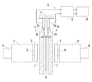
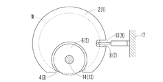
以下、本発明の各実施形態を図面に基づいて詳述する。図1〜図11は本発明を採用した横型両頭平面研削盤を例示する。この横型両頭平面研削盤は、図1、図2に示すように、左右に相対向して配置され且つ薄板状ワークWを保持する左右一対の静圧パッド1,2と、各静圧パッド1,2の凹部3,4に対応して左右方向の軸心廻りに回転自在に配置され且つ静圧パッド1,2により保持されたワークWの左右の両側面を研削する左右一対の研削砥石5,6と、静圧パッド1,2により保持されたワークWを中心廻りに回転させるキャリア(図示省略)と、静圧パッド1,2の切り欠き部7,8に対応してワークWの左右両側に配置された左右一対の測定ヘッド9,10とを備えている。
Hereinafter, embodiments of the present invention will be described in detail with reference to the drawings. 1 to 11 illustrate a horizontal double-sided surface grinder adopting the present invention. As shown in FIGS. 1 and 2, the horizontal double-head surface grinding machine includes a pair of left and right
静圧パッド1,2はワークWを保持する前進位置とワークWから退避する退避位置との間で左右方向に移動自在であり、前進位置ではワークWと対向する保持面側に供給される保持水等の保持流体を介してワークWを静圧的に保持するようになっている。
The
研削砥石5,6はカップ型等であって、軸受箱11,12により回転自在に支持された砥石軸13,14の先端に設けられ、砥石駆動モータ15,16により回転駆動される。軸受箱11,12は摺動案内機構(図示省略)を介して左右方向に移動自在に支持され、切り込み軸駆動モータ(図示省略)の駆動により、切り込み軸(図示省略)、摺動案内機構等を介して左右方向に移動し、研削砥石5,6を研削前進端と研削後退端との間で左右方向に移動させる。
The grinding
測定ヘッド9,10はワークWの両側面の位置を測定するものであって、枢支部9a,10aを介して固定側の支持部材17により揺動自在に支持され、先端の測定子9b,10bがワークWの側面に接触したときの測定ヘッド9,10の枢支部9a,10a廻りの角度変位に応じた電気信号を出力するようになっている。なお、測定ヘッド9,10は静圧パッド1,2に接触するワークWを介して静圧パッド1,2の位置を測定することも可能である。
The measuring heads 9 and 10 measure the positions of both side surfaces of the workpiece W, and are supported by the
各測定ヘッド9,10はインプロセス定寸研削用の定寸装置18の一部を構成するものであって、その出力端側はアンプ19に接続されている。定寸装置18は研削制御装置20に接続されている。定寸装置18は研削中にワークWの研削精度が基準精度内に収まったとき(例えばワークWが所定の厚さになったとき)にゼロ信号を出力して、研削制御装置20の研削動作制御手段21の制御により、スパークアウトその他の所定の動作に移行させるようになっている。
Each measuring
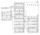
研削制御装置20は図3に示すように、ワークWの挿入から取り出しまでの一連の研削動作を制御する従来公知の研削動作制御手段21の他に、測定ヘッド9,10からの測定値M1,M2に基づいてリアルタイムでワークWの位置を演算する位置演算手段22と、ワークWの試研削等の事前の研削においてワークWの研削精度が基準精度内に収まったときのワークWの相対位置Xを本研削時の研削目標である研削基準位置X0と決定してゼロイング(記憶手段に記憶)する研削基準位置設定手段23と、各ワークWの本研削時に位置演算手段22により演算されたワークWの相対位置Xと既に記憶された研削基準位置X0とを比較して両者の差分(両者の位置ズレ)を求める位置比較手段24と、ワークWの相対位置Xと研削基準位置X0とに差分がある場合に、次の研削時に研削砥石5,6の研削前進端が一致(研削砥石5,6の研削前進端まで前進したときの各測定ヘッド9,10からの測定値M1,M2が研削基準位置X0を決定したときのワークWの両側面の基準値M1r,M2rと一致)するように、ワークWの研削の終了後にその差分に応じて研削砥石5,6の研削後退端を補正する後退端補正手段25と、測定ヘッド9,10からのワークWの両側面の測定値M1,M2と研削基準位置X0を決定したときのワークWの両側面の基準値M1r,M2rとを減算してワークWの両側面の位置R1,R2を算出し、その両側面の位置R1,R2をリアルタイムで比較して差分することにより両研削砥石5,6の砥石摩耗量の違いを算出して、その砥石摩耗量の違いに基づいて両研削砥石5,6の切れ味差を求める切れ味比較手段26と、両研削砥石5,6に切れ味差がある場合に、両研削砥石5,6の切れ味が同じになるように、研削砥石5,6の切れ味に関係する研削条件を両研削砥石5,6の切れ味差に応じて補正する研削条件補正手段27と、ワークWの研削基準位置X0に対する相対位置Xの変化、ワークWの両側面の位置R1,R2等を表示する表示手段28とを備え、ROM、RAM、CPU等を含むマイコン等により構成されている。
As shown in FIG. 3, the grinding
なお、ワークWの両側面の位置R1,R2をリアルタイムで比較することによって、その両側面の位置R1,R2の差により両研削砥石5,6の砥石摩耗量の他に、両研削砥石5,6によるワークWの合計取り代を算出することもできる。
In addition, by comparing the positions R1 and R2 on both sides of the workpiece W in real time, in addition to the amount of grinding wheel wear on both grinding
表示手段28は図4に示すようにワークWの相対位置Xをバーグラフ表示する相対位置表示部29と、ワークWの左右両側面の位置R1,R2をバーグラフ表示するワーク位置表示部30,31とを有する。相対位置表示部29は左右方向に長い横長状であって、この相対位置表示部29にはゼロイングされた研削基準位置X0を中心に左右方向に所定の目盛が付され、その研削基準位置X0に対するワークWの相対位置Xの変化を指針等の指示部29aにより表示するようになっている。
As shown in FIG. 4, the display means 28 includes a relative
ワーク位置表示部30,31は上下方向に長い縦長状であって、ワークWの左右両側面に対応して左右に並べて配置されている。各ワーク位置表示部30,31には上下方向に所定の目盛が付され、ワークWの両側面の位置R1,R2を下から上(又は上から下)に伸びる指示部30a,31aにより表示するようになっている。なお、相対位置表示部29、ワーク位置表示部30,31の方向は任意であり、また相対位置表示部29、ワーク位置表示部30,31は相対位置X、ワークWの両側面の位置R1,R2を数値で表示するようにしても良い。また表示手段28は必要に応じて後述の各情報を表示する表示部(図示省略)を有する。
The work
両頭平面研削盤によりシリコンウェーハ等のワークWの研削中は、研削砥石5,6の砥石摩耗による僅かな砥粒の脱落、ワークWの僅かな形状の違い、ワークWと一対の静圧パッド1,2との間の水膜の微妙な変化等の影響、取り分け研削砥石5,6の砥石摩耗量のバラツキの影響を受けて両研削砥石5,6の切れ味、ワークWの相対位置X、ワークWの両側面の位置R1,R2が時々刻々と変化する。
During grinding of a workpiece W such as a silicon wafer by a double-sided surface grinder, slight abrasive grains are dropped due to wear of the grinding
しかし、表示手段28に相対位置表示部29、ワーク位置表示部30,31を設けて、その相対位置表示部29によりワークWの相対位置Xを表示し、ワーク位置表示部30,31によりワークWの両側面の位置R1,R2を表示することにより、両研削砥石5,6の切れ味、ワークWの相対位置X、ワークWの両側面の位置R1,R2の変化を可視化することができる。
However, a relative
位置演算手段22は砥石駆動モータ15,16の負荷電流の上昇、回転数の低下等から研削砥石5,6によるワークWの挟み込みを判定する挟み込み判定部34と、ワークWの挟み込みの確認後に各測定ヘッド9,10からの測定値M1,M2を取り込んで静圧パッド1,2間のワークWの相対位置X等を演算する位置演算部35とを有する。
The position calculating means 22 includes a pinch determination unit 34 that determines whether the
挟み込み判定部34はワークWの厚みTが既知であることを利用して、ワークWの位置監視のタイミングを研削条件に適宜設定して、研削サイクルの開始後にそのタイミングが到来することにより、研削砥石5,6によるワークWの挟み込みを判断するようにしても良い。位置演算部35は測定ヘッド9,10からの測定値M1,M2に基づいて、静圧パッド1,2間の中心位置に対するワークWの絶対的位置である絶対位置Xabs、静圧パッド1,2間にワークWが適正に保持されるべき研削基準位置X0、静圧パッド1,2間に保持されるワークWの相対位置Xを随時演算して記憶するようになっている。
Using the fact that the thickness T of the workpiece W is known, the pinching determination unit 34 appropriately sets the timing for monitoring the position of the workpiece W as a grinding condition, and the timing comes after the start of the grinding cycle. It may be determined whether the workpiece W is caught by the
研削基準位置設定手段23は研削基準位置X0をゼロイングするゼロイング部36と、その研削基準位置X0が適正か否かを絶対位置Xabsの絶対値|Xabs|に基づいて判定する基準位置判定部37とを有する。
The grinding reference position setting means 23 includes a zeroing unit 36 for zeroing the grinding reference position X0, a reference
ゼロイング部36は試研削等の事前の研削においてワークWの研削精度が基準精度内に収まったとき、例えば定寸装置18が出力するゼロ信号を受信したときに、その時点の各測定ヘッド9,10の測定値M1,M2に基づいて演算された相対位置Xを位置演算部35から読み出して、その相対位置Xを研削目標である研削基準位置X0としてゼロイングするようになっている。従って、相対位置表示部29は研削基準位置X0をゼロとして、この研削基準位置X0に対するワークWの研削中に相対位置Xの変化を指示部29aの左右方向の位置により表示する。
When the grinding accuracy of the workpiece W falls within the reference accuracy in the preliminary grinding such as trial grinding, for example, when the zero signal output from the sizing
基準位置判定部37は位置演算部35で演算された研削基準位置X0のゼロイング時のワークWの静圧パッド1,2間の絶対位置Xabsを読み出して、その絶対位置Xabsの絶対値|Xabs|が研削精度に応じて予め設定された閾値未満であるか否かを判定するようになっており、例えば絶対値|Xabs|が閾値未満であれば、表示手段28に研削基準位置設定範囲内であることを表示して研削基準位置X0のゼロイングを完了し、また絶対値|Xabs|が閾値以上であれば、表示手段28に研削基準位置設定範囲外であることを適宜表示して作業者に精度の確認と精度調整を促す。
The reference
位置比較手段24は本研削の各研削毎にワークWの研削精度が基準精度内に収まったとき、例えば定寸装置18が出力するゼロ信号を受信したときに、その時点の各測定ヘッド9,10の測定値M1,M2に基づいて位置演算部35で演算された相対位置Xを読み出して、この相対位置Xと研削基準位置X0とを比較して、相対位置Xの研削基準位置X0に対する差分(位置ズレ)の有無を判断するようになっている。なお、位置比較手段24は研削基準位置X0に対するワークWの相対位置Xのズレ方向及びズレ量を算出するようになっている。
When the grinding accuracy of the workpiece W falls within the reference accuracy for each grinding of the main grinding, for example, when the zero signal output from the sizing
後退端補正手段25は位置比較手段24の演算によりワークWの相対位置Xと研削基準位置X0との間に差分がある場合に、ゼロ信号の受信から一定時間行われるスパークアウトの終了後に、次回の研削時に研削砥石5,6の研削前進端が研削基準位置X0におけるワークWの両側面の基準値M1r,M2rと一致するように、ワークWの相対位置Xのズレ方向及びズレ量に応じて切り込み軸の研削後退端、即ち研削砥石5,6の研削後退端を補正するようになっている。
When there is a difference between the relative position X of the workpiece W and the grinding reference position X0 by the calculation of the position comparison means 24, the backward
なお、スパークアウトの開始から終了までの一定時間は研削条件に応じて決められている。また研削基準位置X0におけるワークWの両側面の位置(基準値M1r,M2r)は研削砥石5,6の研削前進端を意味する。切り込み軸の研削後退端、即ち研削砥石5,6の研削後退端の補正は、研削砥石5,6の切れ味制御の一つとして機能するので、一対の研削砥石5,6の一方を基準に他方を補正しても良いし、両方を逆方向に補正しても良い。
The fixed time from the start to the end of the spark out is determined according to the grinding conditions. Further, the positions (reference values M1r, M2r) on both sides of the workpiece W at the grinding reference position X0 mean the grinding advance ends of the grinding
切れ味比較手段26は各測定ヘッド9,10からの測定値M1,M2と研削基準位置X0におけるワークWの両側面の基準値M1r,M2rとの減算によりワークWの両側面の位置R1,R2を算出するワーク位置演算部41と、ワークWの両側面の位置R1,R2を比較し差分することにより両研削砥石5,6の砥石摩耗量の違いを算出して、その砥石摩耗量の違いに基づいて切れ味差を判定する切れ味判定部42とを備えている。切れ味判定部42は両研削砥石5,6の切れ味の違いと補正方向を演算するようになっている。なお、ワーク位置演算部41で演算されたワークWの両側面の位置R1,R2は、ワーク位置表示部30,31の指示部30a,31aの変化として表示される。
The sharpness comparison means 26 subtracts the measured values M1 and M2 from the measuring heads 9 and 10 and the reference values M1r and M2r on both sides of the workpiece W at the grinding reference position X0 to obtain the positions R1 and R2 on both sides of the workpiece W. The difference between the grinding wheel wear amounts of the grinding
研削条件補正手段27は研削中に両研削砥石5,6の切れ味差がなくなるようにリアルタイムで研削条件を随時補正する随時補正部39と、当該ワークWの研削終了後に次回の研削に備えて両研削砥石5,6の切れ味の差がなくなるように研削条件を事後補正する事後補正部40と有する。
The grinding condition correction means 27 includes an occasional correction unit 39 that corrects the grinding conditions as needed in real time so that the sharpness difference between the grinding
随時補正部39は切れ味比較手段26によりリアルタイムで演算された両研削砥石5,6の切れ味差に応じて、両研削砥石5,6の切れ味差がなくなるように研削精度に影響のない研削条件、例えば研削砥石5,6の中央側から研削砥石5,6と静圧パッド1,2との間に供給される研削水(研削流体)の流量を制御すべく構成されている。
As needed, the correction unit 39 has grinding conditions that do not affect the grinding accuracy so as to eliminate the sharpness difference between the grinding
事後補正部40は研削条件で決められたゼロ信号の受信から一定時間後に終了するスパークアウトの後に、ゼロ信号の受信時における両研削砥石5,6の切れ味差に応じて、両研削砥石5,6の切れ味の差がなくなるように研削条件を制御する。この場合の事後補正部40による研削条件の補正は、随時補正部39によるリアルタイムでの補正が研削精度に影響を与えない研削水の流量制御等であるのに対して、研削中に補正をすれば研削精度に影響を与えるような研削条件、例えば研削砥石5,6の回転数及び/又は研削砥石5,6の切り込み速度の制御である。なお、研削条件の補正は、各研削砥石5,6の切れ味の違い、補正方向に基づいて行う。
The
次に図5(a)〜(c)を参照しながら、静圧パッド1,2間の隙間Dの算出、静圧パッド1,2間のワークWの位置認識について説明する。図5(a)に示すように左右の静圧パッド1,2間の隙間Dに挿入されたワークWがその隙間Dのどこに位置するかを判断する場合には、事前に測定ヘッド9,10により静圧パッド1,2の位置を測定して、その測定値A1,B2を記憶させておく。
Next, calculation of the gap D between the
この場合、測定ヘッド9,10はその構造上、各静圧パッド1,2の位置を直接測定できないため、次のような方法で測定する。例えば既知の厚みTのワークWを図5(a)に示すように静圧パッド1,2間に配置して測定ヘッド9,10の測定値M1,M2を読み取る。次に図5(b)に示すようにワークWを左の静圧パッド1に接触させたときの測定ヘッド9,10の測定値A1,A2を読み取り、更に図5(c)に示すようにワークWを右の静圧パッド2に接触させたときの測定ヘッド9,10の測定値B1,B2を読み取って記憶させておく。
In this case, since the measuring heads 9 and 10 cannot directly measure the positions of the
左右の静圧パッド1,2の位置は、左右の一方の測定ヘッド9,10の測定値を把握できれば算出できる。例えば右の測定ヘッド10の測定値M2を基準とする場合には(以下、基準を右とする。)、図5(c)に示すようにワークWを右の静圧パッド2に接触させたときの測定ヘッド10の測定値をB2とし、次に図5(b)に示すようにワークWを左の静圧パッド1に接触させたときの右の測定ヘッド10の測定値をA2とすると、ワークWの厚みTが既知であるので、左の静圧パッド1の位置はA2−Tとなり、左右の静圧パッド1,2間の隙間Dは、演算式D=B2−(A2−T)により求めることができる。なお、この測定は機械の設置後や静圧パッド1,2の交換後に行えば良く、通常の研削毎に行う必要はない。
The positions of the left and right
ワークWを搬入・搬出する際に、静圧パッド1,2が真空引き手段によりワークWを吸着して受け渡すような場合には、その真空引手段を利用してワークWを静圧パッド1,2に吸着すれば良い。しかし、一対の静圧パッド1,2の内、例えば右の静圧パッド2には真空引き手段があるが、左の静圧パッド1に真空引き手段がないような場合には、図6、図7に示すような構成の治具43を用いて、厚みTが既知のプレート44を左の静圧パッド1に装着し、そのプレート44に測定ヘッド9,10の測定子9b,10bを接触させて測定すれば良い。
When the
この治具43は、静圧パッド1の切り欠き部7に径方向の外側から着脱自在に嵌合する板状の本体部45と、本体部45の内端側から左の静圧パッド1の背面側へと起立する起立部46と、本体部45の外端側から切り欠き部7の両側に突出する支持部47とを有する。
The
本体部45には左の静圧パッド1の保持面1aに当接するプレート44が一対の取り付けネジ等の固定具48を介して着脱自在に固定されている。起立部46には当接部49が設けられ、その当接部49はバネ等により付勢されて左の静圧パッド1の背面側に弾性的に当接している。各支持部47は取り付けネジ等の固定具50を介して本体部45に着脱自在に固定されている。この支持部47の両端には、バネ等により付勢されて右の静圧パッド2に弾性的に当接する当接部51が設けられている。本体部45には測定子9b,10bがプレート44に接触するように開口52が設けられている。
A
この治具43を介してプレート44を左の静圧パッド1に装着する場合には、プレート44の外周縁を左の静圧パッド1の保持面1aに当接又は近接するように、本体部45を左の静圧パッド1の切り欠き部7に挿入する。そして、起立部46の当接部49を静圧パッド1の背面に当接させて、その押圧力により治具43、プレート44を左の静圧パッド1に装着する。その後、両静圧パッド1,2を接近させると、支持部47の当接部51が右の静圧パッド2に押圧し、また両静圧パッド1,2がプレート44を挟むので、図6及び図7に示すようにプレート44の外周縁を左の静圧パッド1の保持面1aに沿って固定できる。
When the
このようにして左の静圧パッド1にプレート44を装着した後、図6に二点鎖線で示すようにプレート44の両側に測定子9b,10bを接触させて測定ヘッド9,10の測定値M1,M2を読み取れば、真空引き手段のない左の静圧パッド1についてもその位置を容易に測定できる。
After the
静圧パッド1,2間のワークWの位置認識は、次のようにして行う。静圧パッド1,2間に未研削のワークWを挿入した場合、そのワークWは例えば図8(a)に示すように静圧パッド1,2間に保持される。このときのワークWと右の静圧パッド2との間の右側隙間D2は、図8(a)のときのワークWの右側面の測定値M2と、図8(b)に示すようにワークWが右の静圧パッド2に当接したときの測定ヘッド10の測定値B2とから、演算式D2=B2−M2で求めることができる。
The position of the workpiece W between the
ワークWと左の静圧パッド1との間の左側隙間D1も、同様にして図8(a)のときのワークWの左側面の測定値M1と、図8(c)に示すようにワークWが左の静圧パッド1に当接したときの測定ヘッド9の測定値A1とから、演算式D1=A1−M1で求めることができる。
Similarly, the left gap D1 between the workpiece W and the left
従って、ワークWから各静圧パッド1,2までの距離D1,D2が分かるので、各静圧パッド1,2間におけるワークWの位置、例えば絶対位置Xabs、相対位置Xを監視することができ、D1=D2であれば、ワークWは静圧パッド1,2間の中央に位置している。
Accordingly, since the distances D1 and D2 from the workpiece W to the respective
次に図9の流れ図を参照して研削目標である研削基準位置X0を決定し、その研削基準位置X0をゼロイングする方法を説明する。先ず試研削においてワークWを挿入し(ステップS1)、研削サイクルを開始する(ステップS2)。研削サイクルの開始により、各静圧パッド1,2が所定位置まで前進してワークWを静圧により保持した後に、各研削砥石5,6が前進してワークWの両側面を研削する。しかし、両研削砥石5,6がワークWを挟み込むまではワークWの位置が不安定であるため、位置演算手段22の挟み込み判定部34が研削砥石5,6によるワークWの挟み込みを確認した後に(ステップS3)、位置演算部35が各測定ヘッド9,10の測定値M1,M2を取り込んでワークWの位置監視を開始する(ステップS4)。
Next, a method for determining the grinding reference position X0 as a grinding target and zeroing the grinding reference position X0 will be described with reference to the flowchart of FIG. First, a workpiece W is inserted in trial grinding (step S1), and a grinding cycle is started (step S2). By starting the grinding cycle, the respective
ワークWの位置監視が始まると、先ず位置演算部35は静圧パッド1,2間の中心位置に対するワークWの絶対位置Xabsを演算し(ステップS5)、その絶対位置Xabsを表示手段28に表示する(ステップS6)。なお、ワークWの絶対位置Xabsは(D2−D1)/2により演算できる。また位置演算部35はワークWの相対位置Xを演算し(ステップS7)、以前にゼロイングされた基準値M1r,M2rがあれば(ステップS8)、その基準値M1r,M2rに対しての相対位置Xを演算して表示する(ステップS9)。この相対位置Xは演算式{(M1−M1r)−(M2−M2r)}/2により演算する。ゼロイングされた位置がない場合には、各測定ヘッド9,10の測定値M1,M2をそのまま表示する(ステップS8,S10)。
When the position monitoring of the workpiece W starts, first, the
試研削のワークWが所定厚さになれば、定寸装置18からゼロ信号があるので(ステップS11)、そのゼロ信号によりスパークアウトを開始する(ステップS12)。そして、スパークアウトを開始すれば、切り込み軸が停止し、各測定ヘッド9,10がワークWの両側面から退避する。一方、スパークアウトの開始と同時に、位置演算部35で演算されたゼロ信号の受信時点のワークWの相対位置Xを読み込んで(ステップS13)、ゼロイング部36がその相対位置Xを研削目標である研削基準位置X0としてゼロイングし(ステップS14)、また表示手段28に研削基準位置X0をゼロとして表示する。
If the workpiece W for trial grinding has a predetermined thickness, there is a zero signal from the sizing device 18 (step S11), and spark-out is started by the zero signal (step S12). When the spark-out is started, the cutting shaft is stopped, and the measuring heads 9 and 10 are retracted from both side surfaces of the workpiece W. On the other hand, simultaneously with the start of spark-out, the relative position X of the workpiece W at the time of reception of the zero signal calculated by the
またスパークアウトの開始と同時に、基準位置判定部37が位置演算部35で演算されたゼロ信号の受信時(研削基準位置X0をゼロイングしたとき)の静圧パッド1,2間のワークWの絶対位置Xabsの絶対値|Xabs|を読み込んで、その絶対値|Xabs|と要求される研削精度に基づいて予め設定された閾値と比較して、研削基準位置X0がゼロイング位置として誤りがないか否かを判定する(ステップS15)。そして、ワークWの絶対位置Xabsが閾値未満であれば、研削基準位置設定範囲内として表示手段28に表示しゼロイングを完了する(ステップS16)。また絶対値|Xabs|が閾値以上であれば、研削基準位置設定範囲外として表示手段28に表示し(ステップS17)、作業者に精度の確認と精度調整とを促す。
Simultaneously with the start of spark out, the absolute position of the workpiece W between the
この研削基準位置X0のゼロイングはスパークアウト開始と同時に行われる。スパークアウトは研削条件に基づいて予め一定時間に設定されており、その一定時間が経過してスパークアウトが完了すると(ステップS18,S19)、切り込み軸が研削後退端へと移動し(ステップS20)、研削サイクルが終了するので(ステップS21)、試研削後のワークWを取り出し(ステップS22)、その研削後のワークWを人為的に測定し(ステップS23)、研削精度の判定を行う(ステップS24)。 The zeroing of the grinding reference position X0 is performed simultaneously with the start of spark out. The spark-out is set in advance to a certain time based on the grinding conditions. When the spark-out is completed after the lapse of the certain time (steps S18 and S19), the cutting shaft moves to the grinding backward end (step S20). Since the grinding cycle is completed (step S21), the workpiece W after the trial grinding is taken out (step S22), the workpiece W after the grinding is artificially measured (step S23), and the grinding accuracy is determined (step). S24).
なお、研削精度の判定の結果、所定の研削精度が得られない場合、ゼロイングされた研削基準位置X0が研削基準位置範囲外であった場合には、所定の研削精度が得られるように精度調整を行った後、再度ワークWの挿入の作業からやり直し、適正な研削基準位置X0を決定しゼロイングする。 If the predetermined grinding accuracy is not obtained as a result of the judgment of the grinding accuracy, or the zeroed grinding reference position X0 is out of the grinding reference position range, the accuracy adjustment is performed so that the predetermined grinding accuracy is obtained. Then, the work W is inserted again, and an appropriate grinding reference position X0 is determined and zeroed.
次に図10の流れ図を参照しながら、本研削におけるワークWの位置監視と研削砥石5,6の切れ味制御について説明する。先ずワークWを挿入して(ステップS30)、研削サイクルを開始する(ステップS31)。そして、研削サイクルを開始すると、挟み込み判定部34が研削砥石5,6によるワークWの挟み込みを確認した後(ステップS32)、位置演算部35がリアルタイムで測定ヘッド9,10の測定値M1,M2を取り込みながらワークWの位置を監視する(ステップS33)。
Next, the position monitoring of the workpiece W and the sharpness control of the grinding
測定ヘッド9,10の測定値M1,M2を取り込むと、位置演算部35が測定値M1,M2に基づいて現在のワークWの相対位置Xを演算し(ステップS34)、ゼロイングされた研削基準位置X0に対する現在位置を指針等の指示部29aによりリアルタイムで表示する(ステップS35)。
When the measurement values M1 and M2 of the measuring heads 9 and 10 are taken in, the
同時に切れ味比較手段26が両研削砥石5,6の切れ味の違いを判定する。即ち、記憶データの中から研削基準位置X0を決定したときのワークWの両側面の基準値M1r,M2rを読み込んで(ステップS36)、ワーク位置演算部41がその基準値M1r,M2rとその時点の測定値M1,M2とを減算することにより、基準値M1r,M2rに対するワークWの両側面の位置R1,R2を演算した後(ステップS37)、切れ味判定部42がその両側面の位置R1,R2を比較して両研削砥石5,6の砥石摩耗量の違いを算出し、その砥石摩耗量の違いに基づいて両研削砥石5,6の切れ味差の有無を判定する(ステップS38)。
At the same time, the sharpness comparison means 26 determines the difference in sharpness between the grinding
例えば、左の研削砥石5の砥石摩耗量が右の研削砥石6の砥石摩耗量に比較して少なく、左の研削砥石5の切れ味が右の研削砥石6の切れ味よりも悪い場合には、研削中のワークW2は、図11に示すように切れ味の悪い研削砥石5により右方向に押されて切れ味の良い研削砥石6側に移動した状態となっている。
For example, when the grinding wheel wear amount of the
そこで、研削中のワークW2が研削基準位置X0の決定時のワークW1に対して図11に示すような位置関係になれば、そのワークW1の基準値M1r,M2rと、現時点のワークW2の測定値M1,M2とから、ワークW2の左の位置R1を演算式R1=M1−M1rにより、右の位置R2を演算式R2=M2−M2rにより夫々演算できる。 Therefore, if the workpiece W2 being ground has a positional relationship as shown in FIG. 11 with respect to the workpiece W1 when the grinding reference position X0 is determined, the reference values M1r and M2r of the workpiece W1 and the measurement of the current workpiece W2 are performed. From the values M1 and M2, the left position R1 of the workpiece W2 can be calculated by the arithmetic expression R1 = M1-M1r, and the right position R2 can be calculated by the arithmetic expression R2 = M2-M2r.
そして、ワークWの両側面の位置R1,R2の左右差ΔR(=R1−R2)を求めることにより、両研削砥石5,6の切れ味の違いの大きさが判ると同時に、切れ味の悪い方の研削砥石5,6がどれであるかが判る。図11のような場合はΔR<0であり、左の研削砥石5が切れ味不良であることを示す。ΔR=0は両研削砥石5,6の切れ味が同等であることを示す。またΔR>0は図11と逆の場合であり、右の研削砥石6が切れ味不良であることを示す。
And by calculating | requiring the right-and-left difference (DELTA) R (= R1-R2) of position R1, R2 of the both sides | surfaces of the workpiece | work W, the magnitude | size of the sharpness difference of both the grinding
切れ味の判定結果がΔR<0かΔR>0であれば(ステップS38)、研削中に両研削砥石5,6の切れ味の差がなくなるように、随時補正部39が研削精度に影響しない研削水の流量をリアルタイムで補正する(ステップS39)。この場合、左右差ΔR、補正方向(±)に応じて研削水の流量が変化する制御マップを予め作成しておき、その制御マップに基づいて左右差ΔRの大小、正負に対応して研削水の流量を変化させることが望ましい。なお、この研削水の流量の調整は、両研削砥石5,6の切れ味が一致するまで継続しても良いし、制御マップに基づいて制御するだけでも良い。
If the sharpness determination result is ΔR <0 or ΔR> 0 (step S38), the grinding water that the correction unit 39 does not affect the grinding accuracy at any time so as to eliminate the sharpness difference between the grinding
表示手段28のワーク位置表示部30,31は、ワークWの研削中、研削基準位置X0でのワークWの両側面を基準に、そのときの両側面の位置R1,R2を表示する。左右の研削砥石5,6の切れ味が略同じであれば、表示手段28のワーク位置表示部30,31の表示は略同レベルを示し、両研削砥石5,6の切れ味が異なる場合には、図4に示すようにその切れ味差に応じたレベルを表示する。
The workpiece
例えば図11に示すような場合には、両研削砥石5,6の切れ味の違いに応じて図4に示すようにワーク位置表示部30の指示部30aのレベルが低く、ワーク位置表示部31の指示部31aのレベルが高くなる。このためワーク位置表示部30,31の表示を見れば、研削中のワークWの両側面の位置R1,R2の変化として両研削砥石5,6の切れ味の違いを容易に把握することができる。
For example, in the case shown in FIG. 11, the level of the
図11に示すように左の研削砥石5の切れ味が悪い場合には、その切れ味の程度に応じて左の研削砥石5とワークWとの間に供給する研削水の流量を少なくする。これによって研削砥石5から脱落した砥粒の排出が遅くなり、研削砥石5とワークWとの間での砥粒の滞留時間が長くなるため、その砥粒が目立て砥石の役割をして砥石摩耗が促進するため切れ味が良くなる。これによって左右の両研削砥石5,6の切れ味の差を極力少なくすることができる。
As shown in FIG. 11, when the sharpness of the
なお、切れ味の良い研削砥石5,6側の研削水の流量を一定にして、切れ味の悪い研削砥石5,6側の研削水の流量を少なくしても良いし、逆に切れ味の悪い研削砥石5,6側の研削水の流量を一定にして、切れ味の良い研削砥石5,6側の研削水の流量を多くしても良い。また切れ味の良い研削砥石5,6側の研削水の流量を多くしつつ、切れ味の悪い研削砥石5,6側の研削水の流量を少なくする等、両方の研削砥石5,6の研削水の流量を増減しても良い。
The flow rate of the grinding water on the
ワークWが目標厚さになれば定寸装置18からのゼロ信号を受信し(ステップS40)、切り込み軸が停止し各測定ヘッド9,10が退避して、スパークアウトを開始する(ステップS41)。同時に位置比較手段24が位置演算手段22で演算されたゼロ信号の受信時点のワークWの相対位置Xを演算し(ステップS42)、これを研削目標である研削基準位置X0と比較して、研削基準位置X0に対するワークWのズレ量とズレ方向を求める(ステップS43)。また同時にゼロ信号の受信時の測定値M1,M2から、その時点でのワークWの両側面の位置R1,R2の左右差ΔRを演算し(ステップS44)、ワークWの研削終了後に切り込み軸の研削後退端の補正に備える。 When the workpiece W reaches the target thickness, a zero signal is received from the sizing device 18 (step S40), the cutting axis is stopped, the measuring heads 9 and 10 are retracted, and spark out is started (step S41). . At the same time, the position comparison means 24 calculates the relative position X of the workpiece W at the time of reception of the zero signal calculated by the position calculation means 22 (step S42), and compares this with the grinding reference position X0 that is the grinding target to perform grinding. A displacement amount and a displacement direction of the workpiece W with respect to the reference position X0 are obtained (step S43). At the same time, from the measured values M1 and M2 when the zero signal is received, the left / right difference ΔR between the positions R1 and R2 on both sides of the workpiece W at that time is calculated (step S44). Prepare for correction of grinding back end.
スパークアウトは研削条件に基づいて予め一定時間に設定されており、その一定時間が経過してスパークアウトが完了し(ステップS45,S46)、研削サイクルが終了してワークWの研削が終わると(ステップS47)、切り込み軸が研削後退端へと移動する(ステップS48)。 The spark-out is set in advance to a certain time based on the grinding conditions. When the certain time elapses, the spark-out is completed (steps S45 and S46), and when the grinding cycle ends and the grinding of the workpiece W ends ( In step S47), the cutting shaft moves to the grinding backward end (step S48).
ゼロ信号の受信時において、研削基準位置X0に対してワークWの相対位置Xがズレる位置ズレがあれば、研削砥石5,6の切れ味制御の一環として、次回研削時に研削前進端が研削基準位置X0に一致するように、後退端補正手段25が研削砥石5,6の研削後退端、即ち切り込み軸の研削後退端の位置を補正する。従って、次回のワークWの研削時には、ワークWの相対位置Xの位置ズレを吸収した状態で両研削砥石5,6がワークWを切り込むことになり、ワークWの両側面の位置R1,R2を研削基準位置X0に戻すことができる。
When the zero signal is received, if there is a misalignment in which the relative position X of the workpiece W deviates from the grinding reference position X0, as a part of the sharpness control of the grinding
同時にワークWの両側面に左右差ΔRがある場合には、事後補正部40が次回の研削に備えて研削砥石5,6の切れ味に影響を与える研削条件を補正し更新する(ステップS49)。ここでは研削中に変えることのできなかった研削条件、例えば研削砥石5,6の回転数及び/又は研削砥石5,6の切り込み速度を変えることができる。その補正は左右差ΔRの大きさと補正方向に基づいて行う。
At the same time, if there is a left-right difference ΔR on both sides of the workpiece W, the
研削砥石5,6の回転数及び/又は研削砥石5,6の切り込み速度を補正すれば、研削砥石5,6の切れ味を調整できる。例えば研削砥石5,6の回転数を遅くするか、又は切り込み速度を速くすると、研削砥石5,6がワークWを研削する際の研削負荷が大きくなり、砥粒の脱落が進んで新しい砥粒が次々と現れるため、切れ味の悪い研削砥石5,6でもその砥石摩耗の進行によって切れ味を良くすることができる。
If the rotational speed of the grinding
またワークWの相対位置Xの位置ズレに基づいて研削砥石5,6の研削後退端を補正し、ワークWの両側面の位置差ΔRとに基づいて両研削砥石5,6の研削条件を補正することにより、研削砥石5,6の一方のみの研削条件を補正する場合に比較して、研削後のワークWのダメージ、反り等が少なくなり、ワークWの研削精度を更に向上させることができる。
Further, the grinding back ends of the grinding
その後、ワークWを取り出して終了する(ステップS50)。 Thereafter, the work W is taken out and the process ends (step S50).
このようにすれば、両研削砥石5,6の砥石摩耗量のバラツキに起因する切れ味のアンバランスを数値化して、それに基づいて両研削砥石5,6の切れ味が同じになるように自動的に制御することができる。なお、多数のワークWを続けて研削する場合には、同様の手順での操作、制御等を繰り返し行う。
In this way, the unbalance of the sharpness caused by the variation in the grinding wheel wear amount of both grinding
図12は本発明の第2の実施形態を例示する。この第2の実施形態は、研削中のワークWの相対位置Xと静圧パッド1,2にワークWが適正に保持されるべき研削基準位置X0とを比較して両者の差分により両研削砥石5,6の切れ味差をリアルタイムで演算する切れ味比較手段26と、両研削砥石5,6の切れ味差に基づいて両研削砥石5,6の切れ味が略一致するように、両研削砥石5,6とワークWとの間に供給される研削水の流量を制御する等、研削砥石5,6の研削条件を補正する研削条件補正手段27とを備えたものである。
FIG. 12 illustrates a second embodiment of the present invention. In the second embodiment, the relative position X of the workpiece W being ground and the grinding reference position X0 where the workpiece W should be properly held by the
長期間の使用等によって研削砥石5,6に砥石摩耗量に違いが発生すれば、両研削砥石5,6の切り込み量が同じであっても、両研削砥石5,6の研削前進端が相違する。一方、砥石摩耗量の大きい側の研削砥石5,6では自生作用により切れ味が向上して取り代が大であるため、ワークWは砥石摩耗量の小さい側の研削砥石5,6により砥石摩耗量の大きい側の研削砥石5,6へと押されて、ワークWの相対位置Xは砥石摩耗量が大きく切れ味の良い研削砥石5,6側へとズレることになる。
If there is a difference in the wear amount of the grinding
そこで、ワークWの研削中はリアルタイムでワークWの相対位置Xを求め、切れ味比較手段26において、相対位置Xと研削基準位置X0とを比較して両者の差分により両研削砥石5,6の切れ味差に伴うワークWの位置ズレの有無、位置ズレの大小、ズレ方向を演算する。
Thus, during grinding of the workpiece W, the relative position X of the workpiece W is obtained in real time, and the
そして、ワークWの相対位置Xの研削基準位置X0に対する位置ズレがあれば、研削条件補正手段27により、両研削砥石5,6の切れ味差に応じて、即ち位置ズレの大小、ズレ方向に応じて両研削砥石5,6とワークWとの間に供給される研削水の流量を制御する。これによって両研削砥石5,6の切れ味の違いを解消することができる。
If there is a positional deviation of the relative position X of the workpiece W with respect to the grinding reference position X0, the grinding condition correction means 27 responds to the sharpness difference between the grinding
因みに相対位置Xの位置ズレの大小、ズレ方向に応じて両研削砥石5,6の研削水の流量を制御する場合、例えば研削条件等の諸要因を考慮しながら図13に示すような関係で制御すれば良い。
Incidentally, when the flow rate of the grinding water of both grinding
以上、本発明の各実施形態について詳述したが、本発明はこれらの実施形態に限定されるものではなく、本発明の趣旨を逸脱しない範囲で種々の変更が可能である。例えば各実施形態は横型両頭平面研削盤について例示しているが、縦型の両頭平面研削盤でも同様に実施することができる。 As mentioned above, although each embodiment of this invention was explained in full detail, this invention is not limited to these embodiment, A various change is possible in the range which does not deviate from the meaning of this invention. For example, although each embodiment illustrated about the horizontal type | mold double-sided surface grinder, it can implement similarly with a vertical-type double-headed surface grinder.
研削砥石5,6の切れ味差は研削中のワークWの両側面の位置R1,R2を算出し、この両側面の位置R1,R2を比較して両研削砥石5,6の砥石摩耗量の違いを算出して、その両研削砥石5,6の砥石摩耗量の違いに基づいて両研削砥石5,6の切れ味差を判断する方法と、研削中のワークWの相対位置Xを算出し、この相対位置Xと静圧パッド1,2間にワークWが適正に保持されるべき研削基準位置X0とを比較し、その両者の差分により両研削砥石5,6の切れ味差を判断する方法とがあるが、研削中のワークWの両側面の位置R1,R2を測定して、それに基づいて両研削砥石5,6の切れ味を判断する方法であれば、他の方法を採用しても良い。
The difference in sharpness between the grinding
またワークWの両側面の位置R1,R2の左右差ΔRを算出して研削条件を制御する場合にも、左右差ΔRに基づいて研削砥石5,6の切れ味の違いを判定して、その切れ味が略同じとなるように制御しても良いし、左右差ΔRに基づいて研削砥石5,6の砥石摩耗量の違いを判定して、その砥石摩耗量が略同じとなるように制御しても良い。
Further, when the grinding condition is controlled by calculating the left / right difference ΔR between the positions R1, R2 on both side surfaces of the workpiece W, the sharpness difference between the grinding
静圧パッド1,2間の隙間Dの測定において、例えば右の静圧パッド2にしか真空引き手段がなく、しかも治具43もない場合には、市販の隙間ゲージを用いて直接測定しても良い。またワークWの左位置D1は、右の静圧パッド2のパッド位置D2と、隙間ゲージで把握したバッド隙間Dと、既知のワークWの厚みTとにより、次の演算式D1=D−D2−Tで求めることもできる。そして、ワークWの左位置D1が分かれば、その値を元に左パッド位置A1を求め、この左パッド位置A1と左の測定ヘッド9の測定値M1,M2とから、左のパッド位置A1は次の演算式A1=D1+M1で求めることもできる。
When measuring the gap D between the
ゼロイングはワークWが仕上げ寸法になったときに研削基準位置X0に基づいて行うのが最良である。しかし、ワークWへの傷を避けるために、定寸装置18からゼロ信号を受け取って両測定ヘッド9,10がワークWから退避した後も、研削条件で設定されたスパークアウト時間だけワークWが研削されるので、仕上げ寸法でのゼロイングは困難である。従って、定寸装置18からゼロ信号を受け取ったタイミングで行うのが望ましい。
Zeroing is best performed on the basis of the grinding reference position X0 when the workpiece W reaches the finishing dimension. However, in order to avoid scratches on the workpiece W, the workpiece W remains for the spark-out time set in the grinding conditions even after the zero signal is received from the sizing
研削中は静圧パッド1,2により保持された状態で回転するワークWを、回転する研削砥石5,6により両側から研削しながら、測定ヘッド9,10によりワークWの両側面をリアルタイムで測定するため、その両側面の測定値M1,M2には常に微少なバラツキがある。従って、ワークWの相対位置Xは、各測定ヘッド9,10の測定値M1,M2を移動平均処理により求めることが望ましい。
During grinding, the workpiece W rotating while being held by the
また実施形態では定寸装置18の測定ヘッド9,10を利用すると共に、その定寸装置18からのゼロ信号を利用するようにしているが、測定ヘッド9,10を備えた専用の測定手段を用いてワークWの両側面を測定し、定寸装置18からのゼロ信号に代えて、ワークWが所定の研削精度になったときの信号を契機にゼロイング等を行うようにしても良い。
In the embodiment, the measuring heads 9 and 10 of the sizing
測定ヘッド9,10はワークWの両側面に接触する接触式の他、レーザ変位式、静電容量式等の非接触式を使用することも可能であり、ワークWの両側面の位置を測定できるものであればその測定方式は問題ではない。 The measuring heads 9 and 10 can use a non-contact type such as a laser displacement type or a capacitance type in addition to a contact type that contacts both side surfaces of the workpiece W, and measure the positions of both sides of the workpiece W. If possible, the measurement method is not a problem.
測定ヘッド9,10、位置演算手段22によるワークWの位置監視を利用して、研削砥石5,6の交換後の研削位置合わせ作業の自動化を測るようにしても良い。これによって段取り等の時間を削減できると共に、人的要因による研削位置合わせミスの発生を防止できる。つまり、一対の静圧パッド1,2のアライメント調整をしない限り、研削砥石5,6の交換前と研削位置が殆ど変わらないので、静圧パッド1,2の位置合わせは研削砥石5,6の交換前の所定精度の基準値内のワークWの位置に合わせればよく、その位置は機械が記憶しているので、自動化を容易に図ることができる。
By using the position monitoring of the workpiece W by the measuring heads 9 and 10 and the position calculating means 22, it is possible to measure the automation of the grinding positioning operation after the replacement of the grinding
W ワーク
M1,M2 測定値
X 相対位置
X0 研削基準位置
M1r,M2r 基準値
R1,R2 側面の位置
Xabs 絶対位置
1,2 静圧パッド
5,6 研削砥石
9,10 測定ヘッド
20 研削制御装置
22 位置演算手段
23 研削基準位置設定手段
24 位置比較手段
25 後退端補正手段
26 切れ味比較手段
27 研削条件補正手段
W Workpieces M1, M2 Measured value X Relative position X0 Grinding reference position M1r, M2r Reference value R1, R2 Side position
Claims (7)
研削中のワークの静圧パッド間の相対位置を求め、
研削中のワークの相対位置と、静圧パッド間のワークが適正に保持されるべき研削基準位置とを比較し、
両者に差分があるときに、次回の研削時に両研削砥石の研削前進端が研削基準位置と一致するように、当該ワークの研削後に両者の差分に応じて研削砥石の研削後退端を補正する
ことを特徴とする薄板状ワークの研削方法。 When grinding both side surfaces of a thin plate-like workpiece held between a pair of static pressure pads with a pair of grinding wheels moving at substantially the same speed from a grinding back end to a grinding advance end at substantially the same speed,
Find the relative position between the static pressure pads of the workpiece being ground,
Compare the relative position of the workpiece during grinding with the grinding reference position where the workpiece between the hydrostatic pads should be properly held,
When there is a difference between the two, correct the grinding back end of the grinding wheel according to the difference between the two after grinding the workpiece so that the grinding advance end of both grinding wheels matches the grinding reference position at the next grinding. A thin plate-like workpiece grinding method characterized by the above.
ことを特徴とする請求項1に記載の薄板状ワークの研削方法。 The method for grinding a thin plate workpiece according to claim 1, wherein the workpiece position when the grinding accuracy of the workpiece being ground is within the reference accuracy is a relative position.
この研削基準位置を固定的に設定する
ことを特徴とする請求項1又は2に記載の薄板状ワークの研削方法。 The position of the workpiece when the workpiece grinding accuracy is within the reference accuracy in the previous grinding is set as the grinding reference position.
The grinding reference position according to claim 1 or 2, wherein the grinding reference position is fixedly set.
本研削において定寸装置からゼロ信号を受信したときのワークの位置を相対位置とする
ことを特徴とする請求項1〜3の何れかに記載の薄板状ワークの研削方法。 The workpiece position when the zero signal indicating the workpiece sizing is received from the sizing device in the prior grinding is set as the grinding reference position.
The method for grinding a thin plate workpiece according to any one of claims 1 to 3, wherein the position of the workpiece when a zero signal is received from the sizing device in the main grinding is a relative position.
このズレ量及びズレ方向に基づいて研削砥石の研削後退端を補正する
ことを特徴とする請求項1〜4の何れかに記載の薄板状ワークの研削方法。 Comparing the relative position with the grinding reference position to calculate the deviation amount and the deviation direction of the relative position with respect to the grinding reference position,
The method for grinding a thin plate workpiece according to any one of claims 1 to 4, wherein the grinding backward end of the grinding wheel is corrected based on the deviation amount and the deviation direction.
この絶対位置が研削精度により決まる閾値未満のときに研削基準位置を設定する
ことを特徴とする請求項3に記載の薄板状ワークの研削方法。 Measure the absolute position between the static pressure pads of the workpiece when the grinding accuracy of the workpiece is within the reference accuracy in the previous grinding,
The method for grinding a thin workpiece according to claim 3, wherein the grinding reference position is set when the absolute position is less than a threshold value determined by grinding accuracy.
研削中のワークの両側面の位置を測定する一対の測定ヘッドと、
研削中のワークの研削精度が基準精度内に収まったときの測定ヘッドの測定値から、研削中のワークの静圧パッド間の相対位置を求める演算手段と、
研削中のワークの相対位置と、静圧パッド間のワークが適正に保持されるべき研削基準位置とを比較して差分を求める位置比較手段と、
両者に差分があるときに、次回の研削時に両研削砥石の研削前進端が研削基準位置と一致するように、当該ワークの研削後に両者の差分に応じて研削砥石の研削後退端を補正する後退端補正手段とを備えた
ことを特徴とする両頭平面研削盤。 In a double-headed surface grinder that grinds both side surfaces of a thin plate-like workpiece held between a pair of hydrostatic pads by a pair of grinding wheels moving at substantially the same speed from a grinding backward end to a grinding forward end at substantially the same speed,
A pair of measuring heads that measure the positions of both sides of the workpiece being ground;
An arithmetic means for obtaining a relative position between the hydrostatic pads of the workpiece being ground from the measurement value of the measuring head when the grinding accuracy of the workpiece being grounded is within the reference accuracy;
Position comparison means for comparing the relative position of the workpiece being ground and the grinding reference position where the workpiece between the hydrostatic pads should be properly held to obtain a difference;
When there is a difference between the two, the grinding back end of the grinding wheel is corrected according to the difference between the two after grinding the workpiece so that the grinding forward end of both grinding wheels coincides with the grinding reference position at the next grinding. A double-head surface grinder characterized by comprising end correction means.
Priority Applications (4)
| Application Number | Priority Date | Filing Date | Title |
|---|---|---|---|
| JP2011243137A JP5891010B2 (en) | 2011-03-18 | 2011-11-07 | Thin plate workpiece grinding method and double-head surface grinding machine |
| KR1020120024977A KR101891344B1 (en) | 2011-03-18 | 2012-03-12 | Method for grinding thin sheet-like workpiece and double-end surface grinder |
| DE102012204089A DE102012204089A1 (en) | 2011-03-18 | 2012-03-15 | Method for grinding silicon wafer with grinding wheel of e.g. horizontal double-end surface grinder, involves correcting grinding-extending ends of wheels, so that grinding-driving ends of wheels are adapted to each other during grinding |
| TW101108994A TWI558503B (en) | 2011-03-18 | 2012-03-16 | Method for grinding thin sheet-like workpiece and double-end surface grinder |
Applications Claiming Priority (3)
| Application Number | Priority Date | Filing Date | Title |
|---|---|---|---|
| JP2011060520 | 2011-03-18 | ||
| JP2011060520 | 2011-03-18 | ||
| JP2011243137A JP5891010B2 (en) | 2011-03-18 | 2011-11-07 | Thin plate workpiece grinding method and double-head surface grinding machine |
Publications (3)
| Publication Number | Publication Date |
|---|---|
| JP2012210697A JP2012210697A (en) | 2012-11-01 |
| JP2012210697A5 JP2012210697A5 (en) | 2014-11-27 |
| JP5891010B2 true JP5891010B2 (en) | 2016-03-22 |
Family
ID=46757087
Family Applications (1)
| Application Number | Title | Priority Date | Filing Date |
|---|---|---|---|
| JP2011243137A Active JP5891010B2 (en) | 2011-03-18 | 2011-11-07 | Thin plate workpiece grinding method and double-head surface grinding machine |
Country Status (4)
| Country | Link |
|---|---|
| JP (1) | JP5891010B2 (en) |
| KR (1) | KR101891344B1 (en) |
| DE (1) | DE102012204089A1 (en) |
| TW (1) | TWI558503B (en) |
Families Citing this family (10)
| Publication number | Priority date | Publication date | Assignee | Title |
|---|---|---|---|---|
| CN104511814A (en) * | 2014-12-20 | 2015-04-15 | 重庆尹氏天润套装门有限公司 | Wood board processing table with two-side grinding function |
| JP6285375B2 (en) * | 2015-02-17 | 2018-02-28 | 光洋機械工業株式会社 | Double-head surface grinding machine |
| CN107984360A (en) * | 2017-11-20 | 2018-05-04 | 长沙市凤英机械科技有限公司 | A kind of H profile steel multiaspect polishing derusting device |
| CN108687644A (en) * | 2018-03-29 | 2018-10-23 | 芜湖凌梦电子商务有限公司 | A kind of polishing pin of tablet computer production equipment easy to use |
| CN108747667B (en) * | 2018-05-07 | 2019-10-25 | 徐州恒林木业有限公司 | A kind of BMC injection mold plate surface burr remover |
| CN110181383A (en) * | 2019-06-06 | 2019-08-30 | 扬州好管家科技信息咨询有限公司 | A kind of high efficiency burnishing device of lift self-control self-suction type water pump mold processing |
| CN110539237B (en) * | 2019-09-30 | 2021-06-04 | 南通海润机床有限公司 | Liftable double-grinding-wheel structure for grinding machine |
| CN110883661A (en) * | 2019-12-04 | 2020-03-17 | 浙江中慧厨房设备有限公司 | Double-sided polishing machine for steel plate |
| CN111390678A (en) * | 2020-04-24 | 2020-07-10 | 山西潞安太阳能科技有限责任公司 | Silicon wafer grinding machine and using method thereof |
| JP2022074517A (en) * | 2020-11-04 | 2022-05-18 | 株式会社ディスコ | Grinding method for workpiece |
Family Cites Families (6)
| Publication number | Priority date | Publication date | Assignee | Title |
|---|---|---|---|---|
| US4524547A (en) * | 1983-09-06 | 1985-06-25 | Litton Industrial Products, Inc. | Automatic double disc grinder control cycle |
| JP2005238444A (en) * | 1999-05-07 | 2005-09-08 | Shin Etsu Handotai Co Ltd | Double-sided simultaneous grinding method, double-sided simultaneous grinding machine, double-sided simultaneous lapping method and double-sided simultaneous lapping machine |
| JP2003071713A (en) | 2001-08-29 | 2003-03-12 | Nippei Toyama Corp | Grinding apparatus and thickness managing method for wafer |
| JP2003236748A (en) * | 2002-02-14 | 2003-08-26 | Sumitomo Heavy Ind Ltd | Grinder |
| JP2004058175A (en) * | 2002-07-25 | 2004-02-26 | Sumitomo Heavy Ind Ltd | Duplex-head grinding device |
| JP4319092B2 (en) * | 2004-06-03 | 2009-08-26 | 住友重機械工業株式会社 | Double-sided processing equipment |
-
2011
- 2011-11-07 JP JP2011243137A patent/JP5891010B2/en active Active
-
2012
- 2012-03-12 KR KR1020120024977A patent/KR101891344B1/en active IP Right Grant
- 2012-03-15 DE DE102012204089A patent/DE102012204089A1/en active Pending
- 2012-03-16 TW TW101108994A patent/TWI558503B/en active
Also Published As
| Publication number | Publication date |
|---|---|
| TW201249597A (en) | 2012-12-16 |
| DE102012204089A1 (en) | 2012-09-20 |
| KR101891344B1 (en) | 2018-08-24 |
| JP2012210697A (en) | 2012-11-01 |
| TWI558503B (en) | 2016-11-21 |
| KR20120106576A (en) | 2012-09-26 |
Similar Documents
| Publication | Publication Date | Title |
|---|---|---|
| JP5891010B2 (en) | Thin plate workpiece grinding method and double-head surface grinding machine | |
| KR101983395B1 (en) | Double-end surface grinding method and double-end surface grinder | |
| TWI434748B (en) | Method for shape modification of polishing pad | |
| KR101397309B1 (en) | Apparatus and method for machining spectacle lens | |
| US20200033842A1 (en) | Grinding quality estimation model generating device, grinding quality estimating device, poor quality factor estimating device, grinding machine operation command data adjustment model generating device, and grinding machine operation command data updating device | |
| JPH11309657A (en) | Lens processing device for eye-glasses | |
| JP5851803B2 (en) | Thin plate workpiece grinding method and double-head surface grinding machine | |
| JP6023598B2 (en) | Grinding method | |
| KR20050083738A (en) | Both side grinding method and both side grinder of thin disc-like work | |
| JP7305945B2 (en) | Machine Tools | |
| TW201105461A (en) | Device for chamfering glass substrate | |
| US8931899B2 (en) | Method for trimming an opthalmic lens | |
| JP4911810B2 (en) | Workpiece grinding apparatus and grinding method | |
| JP7068096B2 (en) | Grinding method for workpieces | |
| KR20160120237A (en) | Thin plate-shaped workpiece manufacturing method and double-end surface grinding apparatus | |
| JP2708351B2 (en) | Rolling mill, roll grinding device, and rolling method with online roll grinding device | |
| JP2002307303A (en) | Both face grinding method for thin plate disclike workpiece and device thereof | |
| JPH09201768A (en) | Automatic sizing device and method for double-end grinder | |
| JP6163916B2 (en) | Wheel wear measurement method | |
| JP2020114615A (en) | Maintenance support device for machine tool and machine tool system | |
| JP2020114614A (en) | Surface roughness estimation device and machine tool system | |
| JP5578549B2 (en) | Eyeglass lens processing equipment | |
| JPH03149181A (en) | Grinding device | |
| JP2019063939A (en) | Eyeglass lens processing apparatus and eyeglass lens processing program |
Legal Events
| Date | Code | Title | Description |
|---|---|---|---|
| RD01 | Notification of change of attorney |
Free format text: JAPANESE INTERMEDIATE CODE: A7421 Effective date: 20130110 |
|
| RD02 | Notification of acceptance of power of attorney |
Free format text: JAPANESE INTERMEDIATE CODE: A7422 Effective date: 20130206 |
|
| RD04 | Notification of resignation of power of attorney |
Free format text: JAPANESE INTERMEDIATE CODE: A7424 Effective date: 20130213 |
|
| A521 | Request for written amendment filed |
Free format text: JAPANESE INTERMEDIATE CODE: A523 Effective date: 20141009 |
|
| A621 | Written request for application examination |
Free format text: JAPANESE INTERMEDIATE CODE: A621 Effective date: 20141009 |
|
| A977 | Report on retrieval |
Free format text: JAPANESE INTERMEDIATE CODE: A971007 Effective date: 20150710 |
|
| A131 | Notification of reasons for refusal |
Free format text: JAPANESE INTERMEDIATE CODE: A131 Effective date: 20150721 |
|
| A521 | Request for written amendment filed |
Free format text: JAPANESE INTERMEDIATE CODE: A523 Effective date: 20150907 |
|
| A131 | Notification of reasons for refusal |
Free format text: JAPANESE INTERMEDIATE CODE: A131 Effective date: 20151117 |
|
| A521 | Request for written amendment filed |
Free format text: JAPANESE INTERMEDIATE CODE: A523 Effective date: 20151209 |
|
| TRDD | Decision of grant or rejection written | ||
| A01 | Written decision to grant a patent or to grant a registration (utility model) |
Free format text: JAPANESE INTERMEDIATE CODE: A01 Effective date: 20160216 |
|
| A61 | First payment of annual fees (during grant procedure) |
Free format text: JAPANESE INTERMEDIATE CODE: A61 Effective date: 20160222 |
|
| R150 | Certificate of patent or registration of utility model |
Ref document number: 5891010 Country of ref document: JP Free format text: JAPANESE INTERMEDIATE CODE: R150 |
|
| R250 | Receipt of annual fees |
Free format text: JAPANESE INTERMEDIATE CODE: R250 |
|
| R250 | Receipt of annual fees |
Free format text: JAPANESE INTERMEDIATE CODE: R250 |
|
| R250 | Receipt of annual fees |
Free format text: JAPANESE INTERMEDIATE CODE: R250 |
|
| R250 | Receipt of annual fees |
Free format text: JAPANESE INTERMEDIATE CODE: R250 |
|
| R250 | Receipt of annual fees |
Free format text: JAPANESE INTERMEDIATE CODE: R250 |
|
| S533 | Written request for registration of change of name |
Free format text: JAPANESE INTERMEDIATE CODE: R313533 |
|
| R350 | Written notification of registration of transfer |
Free format text: JAPANESE INTERMEDIATE CODE: R350 |
|
| R250 | Receipt of annual fees |
Free format text: JAPANESE INTERMEDIATE CODE: R250 |