JP5578549B2 - Eyeglass lens processing equipment - Google Patents
Eyeglass lens processing equipment Download PDFInfo
- Publication number
- JP5578549B2 JP5578549B2 JP2010084687A JP2010084687A JP5578549B2 JP 5578549 B2 JP5578549 B2 JP 5578549B2 JP 2010084687 A JP2010084687 A JP 2010084687A JP 2010084687 A JP2010084687 A JP 2010084687A JP 5578549 B2 JP5578549 B2 JP 5578549B2
- Authority
- JP
- Japan
- Prior art keywords
- lens
- calibration
- processing
- outer diameter
- input
- Prior art date
- Legal status (The legal status is an assumption and is not a legal conclusion. Google has not performed a legal analysis and makes no representation as to the accuracy of the status listed.)
- Active
Links
Images


Description
本件発明は、眼鏡レンズの周縁を加工具により加工する眼鏡レンズ加工装置に関する。 The present invention relates to a spectacle lens processing apparatus that processes the peripheral edge of a spectacle lens with a processing tool.
眼鏡レンズ加工装置は、眼鏡レンズを保持するレンズチャック軸と、レンズチャック軸を回転するレンズ回転ユニットと、眼鏡レンズの周縁を仕上げ加工するヤゲン仕上げ砥石等の仕上げ加工具と、レンズチャック軸と仕上げ加工具の回転軸とを相対的に移動する移動ユニットと、玉型データ等の加工条件データを入力するデータ入力ユニットと、を備え、入力された玉型データに基づいてレンズ周縁を仕上げ加工具により加工する。加工装置の製造時及び設置時には、レンズの仕上がり外径サイズやレンズの回転角の較正が作業者によって所定の手順で行われ、その較正データがメモリに記憶される(例えば、引用文献1参照)。レンズの周縁加工時には、入力された玉型及び較正データに基づいてレンズの周縁が加工される。 The spectacle lens processing apparatus includes a lens chuck shaft that holds the spectacle lens, a lens rotating unit that rotates the lens chuck shaft, a finishing tool such as a bevel finishing grindstone that finishes the peripheral edge of the spectacle lens, and the lens chuck shaft and finish. A moving unit that moves relative to the rotation axis of the processing tool, and a data input unit that inputs processing condition data such as target lens data, and finishes the lens periphery based on the input target lens data. To process. At the time of manufacture and installation of the processing apparatus, calibration of the finished outer diameter size of the lens and the rotation angle of the lens is performed by a worker according to a predetermined procedure, and the calibration data is stored in the memory (for example, refer to cited document 1). . When processing the periphery of the lens, the periphery of the lens is processed based on the input target lens shape and calibration data.
加工装置が長期間使用されると、加工具の磨耗によって最終的に仕上げ加工されたレンズの外径サイズが変化したり、レンズチャック軸と加工具との位置関係のずれの発生によってレンズの回転角又はヤゲン位置が変化したりすることがある。この場合、外径サイズ等の調整データを得る較正を再度行う必要があるが、従来においては、作業者が実際に加工されたレンズを眼鏡フレームのレンズ枠に入れたときに、較正の必要性を始めて気付くものであった。また、眼鏡店舗に設置された加工装置の較正時には、作業者が実際の加工レンズとは別に専用の較正用レンズを用意し、メモリに記憶されている一定形状の基準玉型によって較正用レンズを加工し、ノギス等の測定器を用いて調整データを得た後、手入力で調整パラメータを変更していた。この場合、調整作業に手間が掛かると共に、較正用のレンズを別に用意する必要があり、余分なコストが掛かる。 If the processing device is used for a long period of time, the outer diameter size of the lens finally finished will change due to wear of the processing tool, or the lens will rotate due to the displacement of the positional relationship between the lens chuck shaft and the processing tool. The corner or bevel position may change. In this case, it is necessary to perform calibration again to obtain adjustment data such as the outer diameter size. Conventionally, however, the necessity of calibration is required when the operator puts the actually processed lens into the lens frame of the spectacle frame. I noticed for the first time. In addition, when calibrating a processing apparatus installed in an eyeglass store, an operator prepares a dedicated calibration lens in addition to the actual processing lens, and uses the reference lens shape of a fixed shape stored in the memory to mount the calibration lens. After processing and obtaining adjustment data using a measuring instrument such as a caliper, the adjustment parameters were changed manually. In this case, it takes time for adjustment work, and it is necessary to prepare a lens for calibration separately, resulting in extra costs.
本件発明は、作業者の較正作業の手間や余分なコストを掛けることなく、レンズの加工精度を確保できる眼鏡レンズ加工装置を提供することを技術課題とする。 This invention makes it a technical subject to provide the spectacle lens processing apparatus which can ensure the processing precision of a lens, without taking the labor of a calibration work of an operator, and extra cost.
上記課題を解決するために、本発明は以下のような構成を備えることを特徴とする。
(1)眼鏡レンズを保持するレンズチャック軸を回転するレンズ回転手段と、眼鏡レンズの周縁を仕上げ加工する仕上げ加工具と、前記仕上げ加工具が取り付けられた加工具回転軸と前記レンズチャック軸との相対的に位置関係を変える移動手段と、玉型データを入力するデータ入力手段と、前記仕上げ加工具によるレンズ加工の較正データを予め記憶している記憶手段と、を備え、入力された玉型(以下、入力玉型)及び前記記憶手段に記憶されている較正データに基づいて前記仕上げ加工具によりレンズの周縁を加工する眼鏡レンズ加工装置において、レンズの外径形状を検知するレンズ外径検知手段と、通常のレンズ加工モードからレンズ加工の較正データを得るための自動較正モードに切換える較正モード切換え手段と、自動較正モードに切換えられたときに、前記レンズチャック軸に保持されたレンズの前記入力玉型に基づく加工に先立ち、前記入力玉型より大きなサイズの較正用玉型を前記入力玉型に基づいて決定する較正用玉型決定手段と、決定された前記較正用玉型に基づいて前記レンズ回転手段及び移動手段を駆動してレンズを仕上げ加工した後、前記レンズ外径検知手段を動作させて検知されたレンズの外径形状と前記較正用玉型とを比較して新たな較正データを得る較正データ取得手段と、前記記憶手段に記憶されている較正データを前記較正データ取得手段によって新たに得られた較正データに書き換える加工制御手段であって、前記較正用玉型に基づいて加工されたレンズについては、引き続き前記入力玉型及び前記記憶手段に新たに記憶された較正データに基づいて前記レンズ回転手段及び移動手段を駆動して加工する加工制御手段と、を備えることを特徴とする。
(2) (1)の眼鏡レンズ加工装置において、前記較正用玉型決定手段は、前記入力玉型より大きなサイズで、レンズのチャック中心を中心にして同一半径の円形部分を含む較正用玉型を決定し、前記較正データ取得手段は、前記較正用玉型の円形部分と前記レンズ外径検知手段により検知された円形部分のレンズ外径とに基づいて外径サイズの較正データを得ることを特徴とする。
(3) (2)の眼鏡レンズ加工装置において、前記較正用玉型決定手段は、さらに、入力玉型より大きな玉型で所定長さ以上の直線部分を含むように較正用玉型を決定し、前記較正データ取得手段は、前記レンズ外径検知手段により検知される前記直線部分の方向と前記較正用玉型の直線部分の方向とに基づいて、レンズの回転角の較正データを得ることを特徴とする。
In order to solve the above problems, the present invention is characterized by having the following configuration.
(1) Lens rotating means for rotating a lens chuck shaft for holding a spectacle lens, a finishing tool for finishing a peripheral edge of the spectacle lens, a processing tool rotating shaft to which the finishing tool is attached, and the lens chuck shaft Moving means, data input means for inputting target lens data, and storage means for storing calibration data for lens processing by the finishing tool in advance. A lens outer diameter for detecting an outer diameter shape of a lens in a spectacle lens processing apparatus that processes a peripheral edge of a lens with the finishing tool based on a mold (hereinafter referred to as an input lens shape) and calibration data stored in the storage means Detection means, calibration mode switching means for switching from a normal lens processing mode to an automatic calibration mode for obtaining lens processing calibration data, and an automatic calibration mode. When the lens is switched to a position, a calibration lens having a size larger than the input lens is determined based on the input lens prior to processing based on the input lens of the lens held on the lens chuck shaft. After the lens is determined by driving the lens rotating means and the moving means based on the determined calibration lens shape, the lens outer diameter detecting means is operated and detected. Calibration data acquisition means for obtaining new calibration data by comparing the outer diameter shape of the lens and the calibration target lens, and calibration data stored in the storage means are newly obtained by the calibration data acquisition means a machining control means for rewriting the calibration data, for the processed lens on the basis of the calibration target lens shape, subsequently newly stored calibration de on the input target lens shape and the storage means Characterized in that and a processing control means for processing by driving the lens rotating means and the moving means based on the data.
(2) In the eyeglass lens processing apparatus according to (1), the calibration lens shape determining means has a larger size than the input lens shape and includes a circular portion having the same radius around the center of the chuck of the lens. The calibration data acquisition means obtains calibration data of the outer diameter size based on the circular portion of the calibration target lens and the lens outer diameter of the circular portion detected by the lens outer diameter detection means. Features.
(3) In the eyeglass lens processing apparatus according to (2), the calibration lens shape determining means further determines the calibration lens shape so as to include a linear portion having a predetermined size and larger than the input lens shape. The calibration data acquisition means obtains calibration data of the rotation angle of the lens based on the direction of the straight line portion detected by the lens outer diameter detection means and the direction of the straight line portion of the calibration target lens. Features.
本発明によれば、作業者の較正作業の手間や余分なコストを掛けることなく、レンズの加工精度を確保できる。 According to the present invention, the processing accuracy of the lens can be ensured without the labor and extra cost of the operator's calibration work.
本発明の実施形態を図面に基づいて説明する。図1は、眼鏡レンズ加工装置の概略構成図である。 Embodiments of the present invention will be described with reference to the drawings. FIG. 1 is a schematic configuration diagram of an eyeglass lens processing apparatus.
加工装置1のベース170上には、一対のレンズチャック軸102L,102Rを回転可能に保持するキャリッジ101が搭載されている。チャック軸102L,102Rに挟持された眼鏡レンズLEの周縁は、スピンドル(加工具回転軸)161aに同軸に取り付けられた加工具としての砥石群168の各砥石に圧接されて加工される。
On the
砥石群168は、粗砥石162、高カーブレンズの前ヤゲン形成用の前ヤゲン加工面及び後ヤゲン形成用の後ヤゲン加工面を持つ仕上げ砥石163、低カーブレンズに使用されるヤゲン形成用のV溝及び平加工面を持つ仕上げ砥石164、ヤゲン形成用のV溝及び平加工面を持つ鏡面砥石165から構成される。砥石スピンドル161aは、モータ160により回転される。これらにより、砥石回転ユニットが構成される。粗加工具及び仕上げ加工具としては、カッターが使用されても良い。
The
レンズチャック軸102Rは、キャリッジ101の右腕101Rに取り付けられたモータ110によりレンズチャック軸102L側に移動される。また、レンズチャック軸102R,102Lは、左腕101Lに取り付けられたモータ120により、ギヤ等の回転伝達機構を介して同期して回転される。モータ120の回転軸には、レンズチャック軸102R,102Lの回転角を検知するエンコーダ121が取り付けられている。これらによりチャック軸回転ユニットが構成される。
The
キャリッジ101は、X軸方向に延びるシャフト103,104に沿って移動可能な支基140に搭載され、モータ145の駆動によりX軸方向(チャック軸の軸方向)に移動される。モータ145の回転軸には、キャリッジ101(すなわち、チャック軸102R,102L)のX軸方向の移動位置を検知するエンコーダ146が取り付けられている。これらによりX軸方向移動ユニットが構成される。また、支基140には、Y軸方向(チャック軸102L、102Rと砥石スピンドル161aとの軸間距離が変動される方向)に延びるシャフト156,157が固定されている。キャリッジ101はシャフト156,157に沿ってY軸方向に移動可能に支基140に搭載されている。支基140にはY軸移動用モータ150が固定されている。モータ150の回転はY軸方向に延びるボールネジ155に伝達され、ボールネジ155の回転によりキャリッジ101はY軸方向に移動される。モータ150の回転軸には、チャック軸のY軸方向の移動位置を検知するエンコーダ158が取り付けられている。これらにより、Y軸方向移動ユニット(軸間距離変動ユニット)が構成される。
The
図1において、キャリッジ101の上方の左右には、レンズコバ位置検知ユニット300F,300Rが設けられている。図2はレンズ前面のコバ位置(玉型上のレンズ前面側のコバ位置)を検知する検知ユニット300Fの概略構成図である。
In FIG. 1, lens edge position detection units 300 </ b> F and 300 </ b> R are provided on the left and right above the
ベース170上に固定されたブロック300aに支基301Fが固定されている。支基301Fには、スライドベース310Fを介して測定子アーム304FがX軸方向にスライド可能に保持されている。測定子アーム304Fの先端部にL型のハンド305Fが固定され、ハンド305Fの先端に測定子306Fが固定されている。測定子306Fは、レンズLEの前面に接触される。スライドベース310Fの下端部にはラック311Fが固定されている。ラック311Fは、支基301F側に固定されたエンコーダ313Fのピニオン312Fと噛み合っている。また、モータ316Fの回転は、ギヤ315F及び314F等の回転伝達機構を介してラック311Fに伝えられ、スライドベース310FがX軸方向に移動される。モータ316Fの駆動により、退避位置に置かれた測定子306FがレンズLE側に移動されると共に、測定子306FをレンズLEに押し当てる測定圧が掛けられる。レンズLEの前面位置の検知時には、玉型形状に基づいてレンズLEが回転されながらレンズチャック軸102L,102RがY軸方向に移動され、エンコーダ313Fによりレンズ前面のX軸方向のコバ位置(玉型上のレンズ前面側のコバ位置)が検知される。
A
レンズ後面のコバ位置検知ユニット300Rの構成は、検知ユニット300Fと左右対称であるので、図2に図示した検知ユニット300Fの各構成要素に付した符号末尾の「F」を「R」に付け替え、その説明は省略する。
Since the configuration of the edge
図1において、装置本体の手前側に面取りユニット200が配置され、キャリッジ部100の後方には、穴加工・溝掘りユニット400が配置されている。これらの構成は、周知のものが使用されるので、詳細は省略する。
In FIG. 1, a
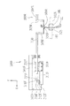
図1において、レンズチャック軸102R側の上側の後方に、レンズ外径検知ユニット500が配置されている。図3(a)は、レンズ外径検知ユニット500の概略構成図である。図3(b)は、ユニット500が持つ測定子520の正面図である。
In FIG. 1, a lens outer
アーム501の一端にレンズLEのエッジに接触される円柱状の測定子520が固定され、アーム501の他端に回転軸502が固定されている。測定子520の中心軸520a及び回転軸502の中心軸502aは、レンズチャック軸102L,102R(X軸方向)に平行な位置関係に配置されている。回転軸502は中心軸502aを中心に回転可能に保持部503に保持されている。保持部503は図1のブロック300aに固定されている。また、回転軸502に扇状のギヤ505が固定され、ギヤ505はモータ510によって回転される。モータ510の回転軸には、ギヤ505と噛みあうピニオンギヤ512が取り付けられている。また、モータ510の回転軸には検知器としてのエンコーダ511が取り付けられている。
A
測定子520は、レンズLEの外径サイズの計測時に接触される円柱部521aと、レンズLEに形成されたヤゲンのX軸方向位置の計測時に使用されるV溝521vを含む小径の円柱部521bと、レンズに形成された溝位置の計測時に使用される突部521cと、を持つ。V溝521vの開き角度vα、仕上げ砥石164が持つヤゲン形成用のV溝の開き角度と同じか、または、それよりも広く形成されている。また、V溝521vの深さvdは、仕上げ砥石164のV溝よりも浅く形成されている。これにより、仕上げ砥石164のV溝によってレンズLEに形成されたヤゲンは、他の部分に干渉することなく、V溝521vの中心に挿入される。
The
レンズ外径検知ユニット500は、通常の眼鏡レンズLEの周縁加工に際して、未加工のレンズLEの外径が玉型に対して足りているか否かを検知するために使用される。レンズLEの外径の測定時には、図4のように、レンズチャック軸102L,102Rが所定の測定位置(回転軸502を中心にして回転される測定子520の中心軸520aの移動軌跡530上)に移動される。モータ510によってアーム501が加工装置1のX軸及びY軸に直交する方向(Z軸方向)に回転されることにより、退避位置に置かれていた測定子520がレンズLE側に移動され、測定子520の円柱部521aがレンズLEのコバ(周縁)に接触される。また、モータ510によって測定子520に所定の測定圧が掛けられる。レンズLEが所定の微小角度ステップ毎で回転され、このときの測定子520の移動がエンコーダ511によって検知されることにより、チャック中心を基準にしたレンズLEの外径サイズが計測される。
The lens outer
なお、レンズ外径検知ユニット500としては、上記のようにアーム501の回転機構で構成される他、加工装置1のX軸及びY軸に直交する方向(Z軸方向)に直線移動される機構であっても良い。
The lens outer
図5は、眼鏡レンズ加工装置の制御ブロック図である。図1に示された各モータ、レンズコバ位置検知ユニット300F、300R、レンズ外径検知ユニット500は、制御ユニット50に接続されている。また、制御ユニット50には、加工条件のデータ入力用のタッチパネル機能を持つディスプレイ5、加工スタートスイッチ等が設けられたスイッチ部7、メモリ51、眼鏡枠形状測定装置(図示を略す)等が接続されている。メモリ51には、レンズ加工における外径サイズ、レンズの回転角及びヤゲン位置等の調整データとしての較正データが記憶されている。
FIG. 5 is a control block diagram of the eyeglass lens processing apparatus. The motors, lens edge
次に、上記の構成を持つ眼鏡レンズ加工装置の動作を説明する。初めに、玉型データ等の加工条件の入力データに基づく、レンズの通常の加工動作を簡単に説明する。眼鏡枠形状測定部2により測定されたリム(レンズ枠)形状に基づいて得られる玉型データは、スイッチ部7に配置されたデータ転送スイッチが押されることにより入力され、メモリ51に記憶される。玉型データは動径長及び動径角の形式で、(rn、ρn)(n=1、2、…、N)として与えられる。玉型データが入力されると、図5に示すように、ディスプレイ5の画面500には、玉型データに基づく左右の玉型図形FTが表示される。画面500aにより、他の加工条件として、玉型の幾何中心FCに対するレンズLEの光学中心の位置関係のレイアウトデータが入力される。入力欄501には装用者の左右の瞳孔間距離(PD値)が入力され、入力欄502には左右のリムの中心間距離(FPD値)が入力され、入力欄503a,503bには玉型の幾何中心FCに対するレンズLEの光学中心OCの高さが入力される。また、加工条件として、レンズの材質、眼鏡フレームの種類、加工モード(レンズ周縁の加工の種別がヤゲン加工である平加工でるか等)、レンズのチャック中心の位置(光学中心、玉型の幾何中心)が、スイッチ511、512、513、514により入力される。
Next, the operation of the eyeglass lens processing apparatus having the above configuration will be described. First, a normal processing operation of a lens based on input data of processing conditions such as target lens data will be briefly described. The target lens shape data obtained based on the shape of the rim (lens frame) measured by the spectacle frame
加工条件データが入力され、レンズLEがチャック軸にチャッキングされた後、スイッチ部7の加工スタートスイッチの信号が入力されると、レンズ外径検知ユニット500が駆動され、未加工のレンズLEの外径サイズが検知される。この検知結果により、入力された玉型に対して、未加工のレンズLEの外径が足りている否かが判定される。次に、レンズコバ位置検知ユニット300F,300Rが駆動され、玉型に対するレンズの前面及び後面のコバ位置が検知される。通常の低カーブレンズのヤゲン加工モードが設定されている場合には、レンズの前面及び後面のコバ位置に基づき、コバ厚を所定の比率(例えば、レンズ前面側から3:7)で分割するようにヤゲン頂点を配置するヤゲン軌跡データが制御ユニット50により演算される。
After the processing condition data is input and the lens LE is chucked on the chuck shaft, when the signal of the processing start switch of the switch unit 7 is input, the lens outer
コバ位置の測定後、レンズ周縁加工に移行される。玉型データに基づいてレンズチャック軸102R,102LのX軸方向及びY軸方向の移動が制御され、粗砥石162によりレンズLEの周縁が粗加工された後、仕上げ用砥石164によりレンズLEの周縁が仕上げ加工される。ヤゲン加工モードが設定されている場合は、ヤゲン軌跡データに基づいてレンズチャック軸102R,102LのX軸移動及びY軸移動が制御され、仕上げ用砥石164によりレンズLEの周縁にヤゲンが形成される。
After measuring the edge position, the process moves to lens peripheral edge processing. The movement of the
次に、定期的に実行される自動較正の動作を説明する。自動較正の定期的な時期としては、代表的にはレンズの加工枚数又は経過時間が採用される。制御ユニット50は、レンズの加工枚数及び経過時間をカウントしており、レンズの加工枚数が所定数に達するか、又は予め設定された一定期間が経過したことをトリガとし、レンズチャック軸に保持されたレンズLEの加工時に加工スタート信号が入力されると、通常のレンズ加工モードから自動較正モードに自動的に切換える。自動較正モードでは、入力された玉型(以下、入力玉型という)に基づくレンズLEの加工に先立ち、入力玉型に基づいて較正用玉型が決定され、この較正用玉型に基づいたレンズの加工と外径サイズ等の計測が自動的に行われる。
Next, an automatic calibration operation that is periodically performed will be described. As the periodic timing of automatic calibration, the number of processed lenses or elapsed time is typically employed. The
図6は、較正用玉型の決定例の図である。図6において、FT1は入力玉型である。FSは較正用玉型である。較正用玉型FSは、外径サイズが小さく加工された場合の変動量を見込み、また、レンズの回転角のずれ(いわゆるAXISずれ)が発生した場合の変動を見込み、入力玉型FT1(rn、ρn)(n=1、2、…、N)より大きなサイズで決定される。また、ヤゲン加工では、仕上げ砥石164により形成されるヤゲンの高さ分を確保できるように、入力玉型FT1より大きなサイズの較正用玉型FSが決定される。これにより、外径サイズが小さく加工され、さらに、レンズの回転角のずれが発生した場合にも、その後の入力玉型FT1に従った補正加工が行え、レンズを無駄にせずに使用できる。
FIG. 6 is a diagram illustrating an example of determining a calibration target lens. In FIG. 6, FT1 is an input target lens. FS is a calibration target lens. The calibration target lens FS is expected to have a fluctuation amount when the outer diameter size is processed to be small, and is expected to have a fluctuation when a lens rotation angle shift (so-called AXIS shift) occurs, the input target lens shape FT1 (rn , Ρn) (n = 1, 2,..., N). In the beveling process, a calibration target lens FS having a size larger than that of the input target lens FT1 is determined so that the height of the bevel formed by the finishing
また、較正用玉型FSは、好ましくは、チャック中心C1(枠心チャックの時は、玉型の幾何中心FCに一致される)を中心にして同一半径Rsの円形部分FSaを少なくとも含む形状に決定される。円形部分FSaは外径サイズが検知される領域であり、レンズの回転ずれの発生を見込んだある角度範囲以上(例えば、5度以上)を少なくとも含めば良い。円形部分FSaの外径サイズが計測されることにより、レンズの回転角にずれが生じている場合でも、その影響が取り除かれた状態で、外径サイズの変動を精度良く検知できる。さらに好ましくは、円形部分FSaは、チャック中心C1を中心にした直径方向に2箇所以上で設定される。直径方向の円形部分FSaの外径サイズが計測されることにより、チャック軸の撓みの影響を排除して、外径サイズの変動を精度良くできる。図6の例では、円形部分FSaは4箇所に設定されている。 Further, the calibration lens FS preferably has a shape including at least a circular portion FSa having the same radius Rs with the chuck center C1 (in the case of the frame center chuck being coincident with the geometric center FC of the lens) as a center. It is determined. The circular portion FSa is a region where the outer diameter size is detected, and it is sufficient to include at least a certain angle range (for example, 5 degrees or more) in which the occurrence of the rotational deviation of the lens is expected. By measuring the outer diameter size of the circular portion FSa, even when the lens rotation angle is deviated, fluctuations in the outer diameter size can be accurately detected in a state where the influence is removed. More preferably, the circular portion FSa is set at two or more locations in the diameter direction around the chuck center C1. By measuring the outer diameter size of the circular portion FSa in the diameter direction, the influence of the deflection of the chuck shaft can be eliminated, and the variation of the outer diameter size can be accurately performed. In the example of FIG. 6, the circular portion FSa is set at four places.
また、較正用玉型FSは、レンズの回転角の変動を検出可能にするために、ある一定以上の長さ(例えば、20mm以上)で一定方向の直線部分FSbを含むように設定されることが好ましい。図6の例では、直線部分FSbは玉型のxy座標のx軸に平行な方向に設定されている。直線部分FSbの方向成分が検知されることにより、レンズの回転角のずれが検出される。 Further, the calibration target lens shape FS is set so as to include a straight portion FSb in a certain direction with a certain length or longer (for example, 20 mm or longer) in order to be able to detect fluctuations in the rotation angle of the lens. Is preferred. In the example of FIG. 6, the straight line portion FSb is set in a direction parallel to the x axis of the xy coordinate of the target lens shape. By detecting the direction component of the straight line portion FSb, a shift in the rotation angle of the lens is detected.
自動較正モードの加工動作を説明する。通常のレンズの加工と同様に、初めにレンズ外径検知ユニット500が駆動され、未加工レンズLEの外径サイズが検知される。ここで、図6の較正用玉型FSは、未加工レンズLEの外径サイズに入るように決定される。較正用玉型FSが決定されると、次に、レンズコバ位置検知ユニット300F,300Rが駆動され、較正用玉型FSに対するレンズの前面及び後面のコバ位置が検知される。そして、検知されたコバ位置に基づいて、ヤゲン形成用のヤゲン軌跡が所定の演算方法により演算される。例えば、レンズの前面のコバ位置から一定距離だけ後面側にシフトした位置にヤゲン頂点が配置されるように、ヤゲン軌跡が演算される。
The machining operation in the automatic calibration mode will be described. Similar to normal lens processing, the lens outer
コバ位置の測定後、レンズの周縁加工に移行される。較正用玉型FSに基づいてレンズチャック軸102R,102LのX軸方向及びY軸方向の移動が制御され、粗砥石162によりレンズLEの周縁が粗加工される。次に、較正用玉型FS及びヤゲン軌跡に基づいてレンズチャック軸102R,102LのX軸方向及びY軸方向の移動が制御され、レンズLEの周縁が仕上げ加工される。このとき、仕上げ用砥石164のV溝によりレンズのコバにヤゲンが形成される。
After the measurement of the edge position, the process proceeds to the peripheral processing of the lens. The movements of the
ヤゲン仕上げ加工の終了後、レンズ外径検知ユニット500が駆動され、較正用玉型FSの円形部分FSaに対応する部分のレンズ形状が計測される。制御ユニット50によりモータ150が駆動され、外径計測の所定の測定位置にチャック軸102L,102Rが位置されると共に、モータ145が駆動され、測定子520の円中部521aが加工済みのヤゲン頂点に接触するようにレンズLEがX軸方向に移動される。その後、退避位置に置かれていた測定子520(円中部521a)がレンズLEのヤゲンに接触され、レンズLEが回転される。エンコーダ511から出力信号により、4箇所の円形部分FSaの半径が計測される。複数の直径方向で得られた円形部分FSaの直径サイズは、平均化処理がされる。これにより、チャック中心C1を基準にして円形部分FSaの直径サイズが得られ、チャック軸の撓みが発生していた場合にも、その影響が取り除かれる。また、レンズの回転角にずれが生じていたとしても、この回転角のずれと分離して外径サイズの変動分のみを検出することができる。検出された円形部分FSaの直径サイズと較正用玉型FSの円形部分FSaの直径サイズとが比較されることにより、外径サイズの調整データΔyが得られる。メモリ51に記憶されている外径サイズの較正データは、新たに得られた調整データΔy分が補正され、書き換えられる。
After finishing the bevel finishing, the lens outer
次に、レンズの回転角の調整データを得る計測工程に移行される。この計測工程では、レンズの外径サイズに変動があった場合にも、これと分離してレンズの回転角の変動を得るために、次のように計測が行われる。図7に示すように、較正用玉型FSの直線部分FSbが加工装置1のY軸方向と一致するように、ヤゲン加工されたレンズLEが回転される。直線部分FSbに測定子520(円柱部521a)が接触され、この状態でY軸のモータ150が駆動されることにより、チャック軸102L,102R(レンズLE)が矢印Bのように、Y軸方向に一定距離ΔY(例えば、10mm)だけ移動される。このときの測定子520の変動情報がエンコーダ511の出力から得られる。レンズLEが距離ΔYだけ移動される間、測定子520に変動が無いときは、直線部分FSbはY軸に平行であり、レンズの回転角に関する調整(較正)は不要とされる。しかし、測定子520に変動がある場合は、その変動量に基づいて回転角に関する調整データが得られる。すなわち、レンズLEが距離ΔYだけ移動される間に、測定子520の変動がΔdだけあった場合、回転角の調整量をΔθとすると、調整量Δθは、tan(Δθ)=Δd/ΔYによって得られる。Δθの調整方向は、変動量Δdの+/−の方向によって決定される。メモリ51に記憶されていた回転角の較正データは、新たに得られた調整データΔθ分だけ補正され、書き換えられる。
Next, the process proceeds to a measurement process for obtaining adjustment data of the rotation angle of the lens. In this measurement process, even when there is a change in the outer diameter size of the lens, the measurement is performed as follows in order to obtain a change in the rotation angle of the lens separately from this. As shown in FIG. 7, the beveled lens LE is rotated so that the straight line portion FSb of the calibration target lens FS coincides with the Y-axis direction of the processing apparatus 1. When the measuring element 520 (
なお、レンズの回転角の調整データを得る計測は次の方法でも行える。すなわち、レンズの外径サイズの計測時と同様に、測定子520をヤゲン加工されたレンズの直線部分FSbに接触させながらレンズLEを回転させることにより、直線部分FSbの形状が得られるので、得られた直線部分FSbの方向と較正用玉型FSの直線部分FSbの方向とが比較されることにより、回転角に関する較正データが得られる。ただし、この方法においては、レンズの外径サイズに変動が有る場合に、外径サイズの変動に応じた補正計算の必要があるため、複雑な補正計算を省いて、精度良く回転角の較正データを得る上では、図7で説明した方法が好ましい。
The measurement for obtaining the adjustment data of the rotation angle of the lens can also be performed by the following method. That is, as in measuring the outer diameter size of the lens, the shape of the linear portion FSb can be obtained by rotating the lens LE while bringing the
次に、ヤゲン位置の計測工程を説明する。図8のように、円形部分FSaに形成されたヤゲン頂点VTが、測定子520の小径の円柱部521bに接触され、X軸のモータ145の駆動により、矢印BAのように、レンズLEが図8上の左方向に移動される。この移動に伴って、ヤゲン頂点VTが円柱部521bに形成されたV溝521vに入ると、エンコーダ511で検出される距離(チャック中心C1から距離)が変動する。エンコーダ511で検出される距離が最小になったときに、ヤゲン頂点のX軸方向の位置となる。このときのX軸方向の移動情報がエンコーダ146から読み取られることにより、ヤゲン位置の位置データが得られる。較正前のヤゲン位置と新たに得られたヤゲン位置とが比較されることにより、ヤゲン位置の調整データΔxが得られ、メモリ51に記憶されていた較正データが補正される。
Next, the process for measuring the bevel position will be described. As shown in FIG. 8, the bevel apex VT formed in the circular portion FSa is brought into contact with the small-diameter
なお、上記のように自動較正モードに切替えられたときには、ディスプレイ5にその旨が表示され、操作者に報知される。これにより、操作者は自動較正の時期が来たことを知ることができると共に、レンズチャック軸に保持されているレンズが自動較正に使用されていることを知ることができ、また、実際のレンズの加工完了までに時間を要することを知ることができ、無用なトラブルを防止できる。
In addition, when it switches to automatic calibration mode as mentioned above, that is displayed on the
以上のようにして外径サイズ、回転角及びヤゲン位置の調整データが自動的に得られた後は、較正用玉型FSに基づいて加工されたレンズLEが、引き続いて実際の入力玉型FT1及びメモリ51に記憶された新たな較正データに基づいて加工される。この加工工程は、前述した通常の加工動作と同じであるので、重複した説明を省略する。仕上げ砥石164による仕上げ加工時には、較正前のY軸移動の制御に関して外径サイズの調整データΔy分が補正され、較正前のレンズ回転の制御に関して調整量Δθ分が補正され、また、較正前のX軸移動の制御に関してヤゲン位置の調整データΔx分が補正される。この補正加工により、レンズの加工精度が確保されるようになる。なお、調整データが得られた後は、制御ユニット50によりカウントされるレンズの加工枚数及び経過時間がリセットされる。
After the adjustment data of the outer diameter size, the rotation angle, and the bevel position is automatically obtained as described above, the lens LE processed based on the calibration target lens FS is continuously input to the actual input target lens FT1. And processing is performed based on the new calibration data stored in the
以上説明した実施形態は種々の変容が可能である。例えば、実際のレンズを使用した自動較正モードは、レンズの加工枚数が一定数に達する等で自動的に切替えられるものとしたが、作業者が必要と判断したときにディスプレイ5に配置されたスイッチ520によって任意に自動較正モードを実行することもできる。また、仕上げ砥石164や粗砥石162の目詰まりによって加工性能が劣化しときには、砥石のダイヤモンド粒の突出を正常に戻すために、ドレス棒によってドレス処理が行われる。このときには所定のスイッチ操作によってドレスモードが実施される。仕上げ砥石164がドレス処理されると、外径サイズが変動し易いので、ドレスモードに続いて、次のレンズ加工時に自動的に自動較正モードに切換えられる。これにより、ドレス処理後の較正作業が適切に実施されるようになり、作業者の手間が省かれる。
The embodiment described above can be variously modified. For example, the automatic calibration mode using an actual lens is automatically switched when the number of processed lenses reaches a certain number, but a switch disposed on the
5 ディスプレイ
50 制御ユニット
51 メモリ
101 キャリッジ
102L,102R レンズチャック軸
120 モータ
150 モータ
161a スピンドル
164 仕上げ砥石
300F,300R レンズコバ位置検知ユニット
306F,306R 測定子
500 レンズ外径検知ユニット
520 測定子
FT1 入力玉型
FS 較正用玉型
FSa 円形部分
FSb 直線部分
5
Claims (3)
レンズの外径形状を検知するレンズ外径検知手段と、
通常のレンズ加工モードからレンズ加工の較正データを得るための自動較正モードに切換える較正モード切換え手段と、
自動較正モードに切換えられたときに、前記レンズチャック軸に保持されたレンズの前記入力玉型に基づく加工に先立ち、前記入力玉型より大きなサイズの較正用玉型を前記入力玉型に基づいて決定する較正用玉型決定手段と、
決定された前記較正用玉型に基づいて前記レンズ回転手段及び移動手段を駆動してレンズを仕上げ加工した後、前記レンズ外径検知手段を動作させて検知されたレンズの外径形状と前記較正用玉型とを比較して新たな較正データを得る較正データ取得手段と、
前記記憶手段に記憶されている較正データを前記較正データ取得手段によって新たに得られた較正データに書き換える加工制御手段であって、前記較正用玉型に基づいて加工されたレンズについては、引き続き前記入力玉型及び前記記憶手段に新たに記憶された較正データに基づいて前記レンズ回転手段及び移動手段を駆動して加工する加工制御手段と、
を備えることを特徴とする眼鏡レンズ加工装置。 A lens rotating means for rotating a lens chuck shaft for holding a spectacle lens, a finishing processing tool for finishing a peripheral edge of the spectacle lens, a processing tool rotating shaft to which the finishing processing tool is attached, and a relative position of the lens chuck shaft Moving means for changing the positional relationship, data input means for inputting the target lens data, and storage means for storing calibration data for lens processing by the finishing tool in advance, In the spectacle lens processing apparatus for processing the peripheral edge of the lens by the finishing tool based on the calibration data stored in the input lens) and the storage means ,
Lens outer diameter detecting means for detecting the outer diameter shape of the lens;
Calibration mode switching means for switching to an automatic calibration mode for obtaining lens processing calibration data from a normal lens processing mode;
Prior to processing based on the input lens of the lens held on the lens chuck shaft when switched to the automatic calibration mode, a calibration lens having a size larger than the input lens is based on the input lens. Calibration target lens determining means to determine;
Based on the determined calibration lens, the lens rotating means and the moving means are driven to finish the lens, and then the lens outer diameter detecting means is operated to detect the lens outer diameter shape and the calibration. Calibration data acquisition means for comparing with the target lens shape to obtain new calibration data;
A machining control means for rewriting the newly obtained calibration data by the calibration data acquisition means a calibration data stored in the storage means, For the processed lens on the basis of the calibration target lens shape, subsequently the Processing control means for driving and processing the lens rotating means and moving means based on the input lens shape and the calibration data newly stored in the storage means,
An eyeglass lens processing apparatus comprising:
Priority Applications (1)
| Application Number | Priority Date | Filing Date | Title |
|---|---|---|---|
| JP2010084687A JP5578549B2 (en) | 2010-03-31 | 2010-03-31 | Eyeglass lens processing equipment |
Applications Claiming Priority (1)
| Application Number | Priority Date | Filing Date | Title |
|---|---|---|---|
| JP2010084687A JP5578549B2 (en) | 2010-03-31 | 2010-03-31 | Eyeglass lens processing equipment |
Publications (3)
| Publication Number | Publication Date |
|---|---|
| JP2011212811A JP2011212811A (en) | 2011-10-27 |
| JP2011212811A5 JP2011212811A5 (en) | 2013-05-16 |
| JP5578549B2 true JP5578549B2 (en) | 2014-08-27 |
Family
ID=44943090
Family Applications (1)
| Application Number | Title | Priority Date | Filing Date |
|---|---|---|---|
| JP2010084687A Active JP5578549B2 (en) | 2010-03-31 | 2010-03-31 | Eyeglass lens processing equipment |
Country Status (1)
| Country | Link |
|---|---|
| JP (1) | JP5578549B2 (en) |
Families Citing this family (1)
| Publication number | Priority date | Publication date | Assignee | Title |
|---|---|---|---|---|
| JP6110703B2 (en) * | 2013-03-28 | 2017-04-05 | Hoya株式会社 | Lens processing control device, lens processing control program, lens shape determination method, and spectacle lens manufacturing method |
Family Cites Families (3)
| Publication number | Priority date | Publication date | Assignee | Title |
|---|---|---|---|---|
| JP3052204B1 (en) * | 1999-02-05 | 2000-06-12 | 株式会社シギヤ精機製作所 | Processing method of spectacle lens by rasping machine |
| JP3740326B2 (en) * | 1999-08-06 | 2006-02-01 | Hoya株式会社 | Spectacle lens processing method, spectacle lens, and spectacle lens processing apparatus |
| WO2008114781A1 (en) * | 2007-03-16 | 2008-09-25 | Hoya Corporation | Method for edging lens of glasses |
-
2010
- 2010-03-31 JP JP2010084687A patent/JP5578549B2/en active Active
Also Published As
| Publication number | Publication date |
|---|---|
| JP2011212811A (en) | 2011-10-27 |
Similar Documents
| Publication | Publication Date | Title |
|---|---|---|
| JP5500583B2 (en) | Eyeglass lens processing equipment | |
| JP4772342B2 (en) | Eyeglass lens processing equipment | |
| US8366512B2 (en) | Eyeglass lens processing apparatus for processing periphery of eyeglass lens and eyeglass lens processing method | |
| KR101397309B1 (en) | Apparatus and method for machining spectacle lens | |
| EP1815941B1 (en) | Eyeglass lens processing apparatus | |
| EP2505306B1 (en) | Eyeglass lens periphery processing apparatus | |
| KR20080089221A (en) | Eyeglass lens grinding machine | |
| KR101848092B1 (en) | Spectacle lens processing apparatus | |
| JP2005074560A (en) | Spectacle lens working device | |
| KR101415475B1 (en) | Eyeglass lens processing apparatus | |
| JP6187742B2 (en) | Eyeglass lens processing equipment | |
| JP5578549B2 (en) | Eyeglass lens processing equipment | |
| EP2529885A2 (en) | Eyeglass lens processing apparatus | |
| JP5500579B2 (en) | Sensor unit for calibration of eyeglass lens processing equipment | |
| JP6187743B2 (en) | Eyeglass lens processing equipment | |
| JP6236786B2 (en) | Eyeglass lens processing equipment | |
| JP5500584B2 (en) | Eyeglass lens processing equipment | |
| JP2023081553A (en) | Spectacle lens shape measurement device, spectacle lens processing apparatus and spectacle lens shape measurement program | |
| JP6836154B2 (en) | Eyeglass lens peripheral processing information setting device, eyeglass lens peripheral processing device, and eyeglass lens peripheral processing information setting program | |
| JP2021133465A (en) | Spectacle lens shape measuring apparatus, spectacle lens processing apparatus comprising the same, and spectacle lens shape measuring program | |
| JPH06230324A (en) | Lens type shape measuring instrument |
Legal Events
| Date | Code | Title | Description |
|---|---|---|---|
| A521 | Request for written amendment filed |
Free format text: JAPANESE INTERMEDIATE CODE: A523 Effective date: 20130328 |
|
| A621 | Written request for application examination |
Free format text: JAPANESE INTERMEDIATE CODE: A621 Effective date: 20130328 |
|
| A977 | Report on retrieval |
Free format text: JAPANESE INTERMEDIATE CODE: A971007 Effective date: 20140220 |
|
| A131 | Notification of reasons for refusal |
Free format text: JAPANESE INTERMEDIATE CODE: A131 Effective date: 20140225 |
|
| A521 | Request for written amendment filed |
Free format text: JAPANESE INTERMEDIATE CODE: A523 Effective date: 20140428 |
|
| TRDD | Decision of grant or rejection written | ||
| A01 | Written decision to grant a patent or to grant a registration (utility model) |
Free format text: JAPANESE INTERMEDIATE CODE: A01 Effective date: 20140603 |
|
| A61 | First payment of annual fees (during grant procedure) |
Free format text: JAPANESE INTERMEDIATE CODE: A61 Effective date: 20140702 |
|
| R150 | Certificate of patent or registration of utility model |
Ref document number: 5578549 Country of ref document: JP Free format text: JAPANESE INTERMEDIATE CODE: R150 |
|
| R250 | Receipt of annual fees |
Free format text: JAPANESE INTERMEDIATE CODE: R250 |
|
| R250 | Receipt of annual fees |
Free format text: JAPANESE INTERMEDIATE CODE: R250 |
|
| R250 | Receipt of annual fees |
Free format text: JAPANESE INTERMEDIATE CODE: R250 |
|
| R250 | Receipt of annual fees |
Free format text: JAPANESE INTERMEDIATE CODE: R250 |
|
| R250 | Receipt of annual fees |
Free format text: JAPANESE INTERMEDIATE CODE: R250 |
|
| R250 | Receipt of annual fees |
Free format text: JAPANESE INTERMEDIATE CODE: R250 |
|
| R250 | Receipt of annual fees |
Free format text: JAPANESE INTERMEDIATE CODE: R250 |