JP5887845B2 - Image processing method and image processing program - Google Patents
Image processing method and image processing program Download PDFInfo
- Publication number
- JP5887845B2 JP5887845B2 JP2011245325A JP2011245325A JP5887845B2 JP 5887845 B2 JP5887845 B2 JP 5887845B2 JP 2011245325 A JP2011245325 A JP 2011245325A JP 2011245325 A JP2011245325 A JP 2011245325A JP 5887845 B2 JP5887845 B2 JP 5887845B2
- Authority
- JP
- Japan
- Prior art keywords
- parallax
- image
- parallax image
- photoelectric conversion
- aperture
- Prior art date
- Legal status (The legal status is an assumption and is not a legal conclusion. Google has not performed a legal analysis and makes no representation as to the accuracy of the status listed.)
- Active
Links
- 238000003672 processing method Methods 0.000 title claims description 12
- 238000006243 chemical reaction Methods 0.000 claims description 90
- 230000004907 flux Effects 0.000 claims description 59
- 238000003384 imaging method Methods 0.000 claims description 48
- 230000003287 optical effect Effects 0.000 claims description 30
- 230000002093 peripheral effect Effects 0.000 claims description 11
- 210000001747 pupil Anatomy 0.000 claims description 11
- 230000003252 repetitive effect Effects 0.000 description 24
- 230000005540 biological transmission Effects 0.000 description 20
- 238000010586 diagram Methods 0.000 description 20
- 230000005484 gravity Effects 0.000 description 17
- 238000000034 method Methods 0.000 description 16
- 230000008569 process Effects 0.000 description 7
- 230000035945 sensitivity Effects 0.000 description 5
- 239000003086 colorant Substances 0.000 description 3
- 230000006872 improvement Effects 0.000 description 3
- 238000004519 manufacturing process Methods 0.000 description 3
- 238000004040 coloring Methods 0.000 description 2
- 230000006870 function Effects 0.000 description 2
- 230000004048 modification Effects 0.000 description 2
- 238000012986 modification Methods 0.000 description 2
- 239000000758 substrate Substances 0.000 description 2
- 230000009471 action Effects 0.000 description 1
- 230000007812 deficiency Effects 0.000 description 1
- 238000001514 detection method Methods 0.000 description 1
- 230000000694 effects Effects 0.000 description 1
- 230000000737 periodic effect Effects 0.000 description 1
- 239000012466 permeate Substances 0.000 description 1
- 239000000047 product Substances 0.000 description 1
- 230000002194 synthesizing effect Effects 0.000 description 1
Images


Description
本発明は、画像処理方法および画像処理プログラムに関する。 The present invention relates to an image processing method and an image processing program.
2つの撮影光学系を用いて、右目用の画像と左目用の画像とから成るステレオ画像を撮像するステレオ撮像装置が知られている。このようなステレオ撮像装置は、2つの撮像光学系を一定の間隔で配置することにより、同一の被写体を撮像して得られる2つの画像に視差を生じさせる。
[先行技術文献]
[特許文献]
[特許文献1] 特開平8−47001号公報
A stereo imaging device that captures a stereo image composed of a right-eye image and a left-eye image using two imaging optical systems is known. Such a stereo imaging device causes parallax to occur in two images obtained by imaging the same subject by arranging two imaging optical systems at regular intervals.
[Prior art documents]
[Patent Literature]
[Patent Document 1] JP-A-8-47001
しかしながら、複数の視差を生じさせる画像を取得するには、その数に応じた複雑な撮影光学系を用意しなければならなかった。 However, in order to acquire an image that generates a plurality of parallaxes, it has been necessary to prepare a complicated photographing optical system corresponding to the number of images.
本発明の第1の態様における画像処理方法は、二次元的に配された複数の光電変換素子に対して、複数の視差に対応した複数種類の開口マスクを一対一に対応させて設けた撮像素子により撮像された複数の第1視差画像を取得する第1視差画像取得段階と、複数の光電変換素子全体に対して設けられた絞りにより、第1視差画像取得段よりも入射光の光軸に対する周縁の光束を遮光して、撮像素子により撮像された複数の第2視差画像を取得する第2視差画像取得段階と、複数の視差のそれぞれについて、第1視差画像と第2視差画像と、の差分に基づいて、複数種類の開口マスクに対応した複数の視差とは異なる新たな視差に対応した第3視差画像を生成する視差画像生成段階とを備える。 In the image processing method according to the first aspect of the present invention, imaging is provided in which a plurality of types of aperture masks corresponding to a plurality of parallaxes are provided in a one-to-one correspondence with a plurality of two-dimensionally arranged photoelectric conversion elements. The first parallax image acquisition stage that acquires a plurality of first parallax images captured by the element, and the optical axis of the incident light more than the first parallax image acquisition stage by the diaphragm provided for the entire plurality of photoelectric conversion elements A second parallax image acquisition step of acquiring a plurality of second parallax images captured by an imaging device by shielding a peripheral luminous flux with respect to the first parallax image and a second parallax image for each of the plurality of parallaxes; And a parallax image generation step of generating a third parallax image corresponding to a new parallax different from a plurality of parallaxes corresponding to a plurality of types of aperture masks.
本発明の第2の態様における画像処理方法は、二次元的に配された複数の光電変換素子に対して、複数の視差に対応した複数種類の開口マスクを一対一に対応させて設けた撮像素子により撮像された複数の第1視差画像を取得する第1視差画像取得段階と、複数の光電変換素子全体に対して設けられた絞りにより、第1視差画像取得段よりも入射光の光軸に対する周縁の光束を遮光して、撮像素子により撮像された複数の第2視差画像を取得する第2視差画像取得段階と、第1視差画像と第2視差画像とを互いに、異なる視差に対応付けて、視差画像群を生成する画像群生成段階とを備える。 In the image processing method according to the second aspect of the present invention, imaging is provided in which a plurality of types of aperture masks corresponding to a plurality of parallaxes are provided in a one-to-one correspondence with a plurality of photoelectric conversion elements arranged two-dimensionally. The first parallax image acquisition stage that acquires a plurality of first parallax images captured by the element, and the optical axis of the incident light more than the first parallax image acquisition stage by the diaphragm provided for the entire plurality of photoelectric conversion elements The second parallax image acquisition step of acquiring a plurality of second parallax images picked up by the imaging device by shielding the peripheral luminous flux with respect to the image, and associating the first parallax image and the second parallax image with different parallaxes And an image group generation stage for generating a parallax image group.
本発明の第3の態様における画像処理プログラムは、二次元的に配された複数の光電変換素子に対して、複数の視差に対応した複数種類の開口マスクを一対一に対応させて設けた撮像素子により撮像された複数の第1視差画像を取得する第1視差画像取得ステップと、複数の光電変換素子全体に対して設けられた絞りにより、第1視差画像取得段よりも入射光の光軸に対する周縁の光束を遮光して、撮像素子により撮像された複数の第2視差画像を取得する第2視差画像取得ステップと、複数の視差のそれぞれについて、第1視差画像と第2視差画像と、の差分に基づいて、複数種類の開口マスクに対応した複数の視差とは異なる新たな視差に対応した第3視差画像を生成する視差画像生成ステップとをコンピュータに実行させる。 The image processing program according to the third aspect of the present invention is an image pickup in which a plurality of types of aperture masks corresponding to a plurality of parallaxes are provided in a one-to-one correspondence with a plurality of photoelectric conversion elements arranged two-dimensionally. The first parallax image acquisition step for acquiring a plurality of first parallax images captured by the element, and the optical axis of the incident light more than the first parallax image acquisition stage by the diaphragm provided for the entire plurality of photoelectric conversion elements. A second parallax image acquisition step of acquiring a plurality of second parallax images captured by an imaging device by shielding a peripheral luminous flux with respect to the first parallax image and a second parallax image for each of the plurality of parallaxes; Based on the difference, the computer executes a parallax image generation step for generating a third parallax image corresponding to a new parallax different from the plurality of parallaxes corresponding to the plurality of types of aperture masks.
本発明の第4の態様における画像処理プログラムは、二次元的に配された複数の光電変換素子に対して、複数の視差に対応した複数種類の開口マスクを一対一に対応させて設けた撮像素子により撮像された複数の第1視差画像を取得する第1視差画像取得ステップと、複数の光電変換素子全体に対して設けられた絞りにより、第1視差画像取得段よりも入射光の光軸に対する周縁の光束を遮光して、撮像素子により撮像された複数の第2視差画像を取得する第2視差画像取得ステップと、第1視差画像と第2視差画像とを互いに、異なる視差に対応付けて、視差画像群を生成する画像群生成ステップとをコンピュータにより実行させる。 The image processing program according to the fourth aspect of the present invention is an image pickup in which a plurality of types of aperture masks corresponding to a plurality of parallaxes are provided in a one-to-one correspondence with a plurality of photoelectric conversion elements arranged two-dimensionally. The first parallax image acquisition step for acquiring a plurality of first parallax images captured by the element, and the optical axis of the incident light more than the first parallax image acquisition stage by the diaphragm provided for the entire plurality of photoelectric conversion elements. The second parallax image acquisition step of acquiring a plurality of second parallax images captured by the imaging element by shielding the peripheral luminous flux with respect to the first parallax image and the second parallax image are associated with different parallaxes. Then, an image group generation step for generating a parallax image group is executed by a computer.
なお、上記の発明の概要は、本発明の必要な特徴の全てを列挙したものではない。また、これらの特徴群のサブコンビネーションもまた、発明となりうる。 It should be noted that the above summary of the invention does not enumerate all the necessary features of the present invention. In addition, a sub-combination of these feature groups can also be an invention.
以下、発明の実施の形態を通じて本発明を説明するが、以下の実施形態は特許請求の範囲にかかる発明を限定するものではない。また、実施形態の中で説明されている特徴の組み合わせの全てが発明の解決手段に必須であるとは限らない。 Hereinafter, the present invention will be described through embodiments of the invention, but the following embodiments do not limit the invention according to the claims. In addition, not all the combinations of features described in the embodiments are essential for the solving means of the invention.
撮像装置の一形態である本実施形態に係るデジタルカメラは、1つのシーンについて複数の視点数の画像を一度の撮影により生成する。さらに、本実施形態に係るデジタルカメラは、同一の撮影位置から絞り値を変えて撮影することで、同一のシーンについて撮影時に生成した上記複数の視点とは別の視点に対応する画像を生成する。互いに視点の異なるそれぞれの画像を視差画像と呼ぶ。 The digital camera according to the present embodiment, which is one form of the imaging apparatus, generates images with a plurality of viewpoints for one scene by one shooting. Furthermore, the digital camera according to the present embodiment generates an image corresponding to a viewpoint different from the plurality of viewpoints generated at the time of shooting for the same scene by shooting with the aperture value changed from the same shooting position. . Each image having a different viewpoint is called a parallax image.
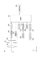
図1は、本発明の実施形態に係るデジタルカメラ10の構成を説明する図である。デジタルカメラ10は、撮影光学系としての撮影レンズ20を備え、光軸21に沿って入射する被写体光束を撮像素子100へ導く。撮影レンズ20は、デジタルカメラ10に対して着脱できる交換式レンズであっても構わない。デジタルカメラ10は、絞り40、撮像素子100、駆動部204、制御部201、A/D変換回路202、メモリ203、画像処理部205、メモリカードIF207、操作部208、表示部209、LCD駆動回路210およびAFセンサ211を備える。
FIG. 1 is a diagram illustrating the configuration of a
なお、図示するように、撮像素子100へ向かう光軸21に平行な方向をz軸プラス方向と定め、z軸と直交する平面において紙面手前へ向かう方向をx軸プラス方向、紙面上方向をy軸プラス方向と定める。以降のいくつかの図においては、図1の座標軸を基準として、それぞれの図の向きがわかるように座標軸を表示する。
As shown in the figure, the direction parallel to the
撮影レンズ20は、複数の光学レンズ群から構成され、シーンからの被写体光束をその焦点面近傍に結像させる。なお、図1では撮影レンズ20を説明の都合上、瞳近傍に配置された仮想的な1枚のレンズで代表して表している。
The taking
絞り40は、撮影レンズ20と共に光軸21に沿って配置される。図1で絞り40は光軸21に沿って撮影レンズ20よりも撮像素子100側に配置されているが、撮影レンズ20が複数のレンズ群を有する場合には、光軸21に沿って当該光学レンズ群のいずれか間に配置される。絞り40の一例は、複数の絞り羽根を有する虹彩絞りである。絞り40が虹彩絞りの場合には、制御部201の制御により、複数の絞り羽根が電磁駆動されて、被写体光束の通過光量を段階的に制限する。絞り40は、撮像素子100の全体に対して1つ設けられる。
The
撮像素子100は、撮影レンズ20の焦点面近傍に配置されている。撮像素子100は、二次元的に複数の光電変換素子が配された、例えばCCD、CMOSセンサ等のイメージセンサである。撮像素子100は、駆動部204によりタイミング制御されて、受光面上に結像された被写体像を画像信号に変換してA/D変換回路202へ出力する。
The
A/D変換回路202は、撮像素子100が出力する画像信号をデジタル画像信号に変換してメモリ203へ出力する。画像処理部205は、メモリ203をワークスペースとして種々の画像処理を施し、画像データを生成する。画像処理部205は、異なる絞り値によって撮影された複数の視差画像データから新たな視差画像データを生成する。
The A /
画像処理部205は、他にも、撮像素子100の画素配列に即して、入力される画像信号から非視差画像データとしての2D画像データおよび視差画像データを生成したり、選択された画像フォーマットに従って画像データを調整する機能も担う。生成された画像データは、LCD駆動回路210により表示信号に変換され、表示部209に表示される。また、メモリカードIF207に装着されているメモリカード220に記録される。
In addition, the
AFセンサ211は、被写体空間に対して複数の測距点が設定された位相差センサであり、それぞれの測距点において被写体像のデフォーカス量を検出する。一連の撮影シーケンスは、操作部208がユーザの操作を受け付けて、制御部201へ操作信号を出力することにより開始される。撮影シーケンスに付随するAF,AE等の各種動作は、制御部201に制御されて実行される。例えば、制御部201は、AFセンサ211の検出信号を解析して、撮影レンズ20の一部を構成するフォーカスレンズを移動させる合焦制御を実行する。
The
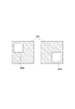
次に、撮像素子100の構成について詳細に説明する。図2は、本発明の実施形態に係る撮像素子の断面を表す概略図である。図2(a)は、カラーフィルタ102と開口マスク103が別体で構成される撮像素子100の断面概略図である。また、図2(b)は、撮像素子100の変形例として、カラーフィルタ部122と開口マスク部123が一体的に構成されたスクリーンフィルタ121を備える撮像素子120の断面外略図である。
Next, the configuration of the
図2(a)に示すように、撮像素子100は、被写体側から順に、マイクロレンズ101、カラーフィルタ102、開口マスク103、配線層105および光電変換素子108が配列されて構成されている。光電変換素子108は、入射する光を電気信号に変換するフォトダイオードにより構成される。光電変換素子108は、基板109の表面に二次元的に複数配列されている。
As shown in FIG. 2A, the
光電変換素子108により変換された画像信号、光電変換素子108を制御する制御信号等は、配線層105に設けられた配線106を介して送受信される。また、各光電変換素子108に一対一に対応して設けられた開口部104を有する開口マスク103が、配線層に接して設けられている。開口部104は、後述するように、対応する光電変換素子108ごとにシフトさせて、相対的な位置が厳密に定められている。詳しくは後述するが、この開口部104を備える開口マスク103の作用により、光電変換素子108が受光する被写体光束に視差が生じる。
An image signal converted by the
一方、視差を生じさせない光電変換素子108上には、開口マスク103が存在しない。別言すれば、対応する光電変換素子108に対して入射する被写体光束を制限しない、つまり有効光束の全体を通過させる開口部104を有する開口マスク103が設けられているとも言える。視差を生じさせることはないが、実質的には配線106によって形成される開口107が入射する被写体光束を規定するので、配線106を、視差を生じさせない有効光束の全体を通過させる開口マスクと捉えることもできる。開口マスク103は、各光電変換素子108に対応して別個独立に配列しても良いし、カラーフィルタ102の製造プロセスと同様に複数の光電変換素子108に対して一括して形成しても良い。
On the other hand, the
カラーフィルタ102は、開口マスク103上に設けられている。カラーフィルタ102は、各光電変換素子108に対して特定の波長帯域を透過させるように着色された、光電変換素子108のそれぞれに一対一に対応して設けられるフィルタである。カラー画像を出力するには、互いに異なる少なくとも2種類のカラーフィルタが配列されれば良いが、より高画質のカラー画像を取得するには3種類以上のカラーフィルタを配列すると良い。例えば赤色波長帯を透過させる赤フィルタ、緑色波長帯を透過させる緑フィルタ、および青色波長帯を透過させる青フィルタを格子状に配列すると良い。具体的な配列については後述する。
The
マイクロレンズ101は、カラーフィルタ102上に設けられている。マイクロレンズ101は、入射する被写体光束のより多くを光電変換素子108へ導くための集光レンズである。マイクロレンズ101は、光電変換素子108のそれぞれに一対一に対応して設けられている。マイクロレンズ101は、撮影レンズ20の瞳中心と光電変換素子108の相対的な位置関係を考慮して、より多くの被写体光束が光電変換素子108に導かれるようにその光軸がシフトされていることが好ましい。さらには、開口マスク103の開口部104の位置と共に、後述の特定の被写体光束がより多く入射するように配置位置が調整されても良い。
The
このように、各々の光電変換素子108に対応して一対一に設けられる開口マスク103、カラーフィルタ102およびマイクロレンズ101の一単位を画素と呼ぶ。特に、視差を生じさせる開口マスク103が設けられた画素を視差画素、視差を生じさせる開口マスク103が設けられていない画素を視差なし画素と呼ぶ。例えば、撮像素子100の有効画素領域が24mm×16mm程度の場合、画素数は1200万程度に及ぶ。
As described above, one unit of the
なお、集光効率、光電変換効率が良いイメージセンサの場合は、マイクロレンズ101を設けなくても良い。また、裏面照射型イメージセンサの場合は、配線層105が光電変換素子108とは反対側に設けられる。
Note that in the case of an image sensor with good light collection efficiency and photoelectric conversion efficiency, the
カラーフィルタ102と開口マスク103の組み合わせには、さまざまなバリエーションが存在する。図2(a)において、開口マスク103の開口部104に色成分を持たせれば、カラーフィルタ102と開口マスク103を一体的に形成することができる。また、特定の画素を被写体の輝度情報を取得する画素として特化させる場合、その画素には、対応するカラーフィルタ102を設けなくても良い。あるいは、可視光のおよそ全ての波長帯域を透過させるように、着色を施さない透明フィルタを配列しても良い。
There are various variations in the combination of the
輝度情報を取得する画素を視差画素とする場合、つまり、視差画像をモノクロ画像として出力するのであれば、図2(b)として示す撮像素子120の構成を採用し得る。すなわち、カラーフィルタとして機能するカラーフィルタ部122と、開口部104を有する開口マスク部123とが一体的に構成されたスクリーンフィルタ121を、マイクロレンズ101と配線層105の間に配設することができる。
When a pixel for obtaining luminance information is a parallax pixel, that is, when a parallax image is output as a monochrome image, the configuration of the image sensor 120 shown in FIG. 2B can be adopted. That is, the screen filter 121 in which the color filter part 122 that functions as a color filter and the opening mask part 123 having the opening 104 are integrally formed may be disposed between the
スクリーンフィルタ121は、カラーフィルタ部122において例えば青緑赤の着色が施され、開口マスク部123において開口部104以外のマスク部分が黒の着色が施されて形成される。スクリーンフィルタ121を採用する撮像素子120は、撮像素子100に比較して、マイクロレンズ101から光電変換素子108までの距離が短いので、被写体光束の集光効率が高い。
The screen filter 121 is formed by, for example, blue-green-red coloring in the color filter portion 122 and black in the opening mask portion 123 other than the opening portion 104. Since the image sensor 120 that employs the screen filter 121 has a shorter distance from the
次に、開口マスク103の開口部104と、生じる視差の関係について説明する。図3は、第1の実施形態に係る撮像素子100の一部を拡大した様子を表す概略図である。ここでは、説明を簡単にすべく、カラーフィルタ102の配色については後に言及するまで考慮しない。カラーフィルタ102の配色に言及しない以下の説明においては、同色のカラーフィルタ102を有する視差画素のみを寄せ集めたイメージセンサであると捉えることができる。したがって、以下に説明する繰り返しパターンは、同色のカラーフィルタ102における隣接画素として考えても良い。
Next, the relationship between the opening 104 of the
図3に示すように、開口マスク103は2種類あって、一方は開口部104lを有し、他方は開口部104rを有する。開口部104l、104rはいずれも長方形である。開口部104lおよび104rは、それぞれの画素に対して相対的にシフトして設けられている。そして、隣接する画素同士においても、それぞれの開口部104lおよび104rは互いに変位した位置に設けられている。
As shown in FIG. 3, there are two types of opening
図3の例において、開口部104lは−x方向にシフトしており、開口部104rはx方向にシフトしている。撮像素子100の全体は、開口部104lを有する開口マスク103と開口部104rを有する開口マスク103とを有する2つの視差画素を一組とする光電変換素子群が、二次元的かつ周期的に配列されている。つまり、撮像素子100は、上記光電変換素子群を含む繰り返しパターン110が、周期的に敷き詰められている。ここで、x方向は、例えば、デジタルカメラ10を横位置で撮像する場合における左右方向である。
In the example of FIG. 3, the opening 104l is shifted in the −x direction, and the opening 104r is shifted in the x direction. The
図4は、視差画素と被写体の関係を説明する概念図である。特に図4(a)は撮像素子100のうち光軸21と直交する中心に配列されている繰り返しパターン110tの光電変換素子群を示し、図4(b)は周辺部分に配列されている繰り返しパターン110uの光電変換素子群を模式的に示している。図4(a)、(b)における被写体30は、撮影レンズ20に対して合焦位置に存在する。図4(c)は、図4(a)に対応して、撮影レンズ20に対して非合焦位置に存在する被写体30を捉えた場合の関係を模式的に示している。
FIG. 4 is a conceptual diagram illustrating the relationship between the parallax pixels and the subject. 4A shows a photoelectric conversion element group of a
まず、撮影レンズ20が合焦状態に存在する被写体30を捉えている場合の、視差画素と被写体の関係を説明する。被写体光束は、撮影レンズ20の瞳を通過して撮像素子100へ導かれるが、被写体光束が通過する全体の断面領域に対して、2つの部分領域PlおよびPrが規定されている。そして、例えば繰り返しパターン110t、110uを構成する光電変換素子群の紙面左側の画素は、拡大図からもわかるように、部分領域Prから射出された被写体光束のみが光電変換素子108へ到達するように、開口マスク103の開口部104rの位置が定められている。同様に、右側の画素に向かって、部分領域Plに対応して開口部104lの位置が定められている。
First, the relationship between the parallax pixels and the subject when the photographing
別言すれば、例えば部分領域Prと左側画素の相対的な位置関係によって定義される、部分領域Prから射出される被写体光束の主光線Rrの傾きにより、開口部104rの位置が定められていると言っても良い。そして、合焦位置に存在する被写体30からの被写体光束を、開口部104rを介して光電変換素子108が受光する場合、その被写体光束は、点線で図示するように、光電変換素子108上で結像する。同様に、右側の画素に向かって、主光線Rlの傾きにより開口部104lの位置が、定められていると言える。
In other words, the position of the opening 104r is determined by the inclination of the principal ray Rr of the subject light beam emitted from the partial region Pr, which is defined by the relative positional relationship between the partial region Pr and the left pixel, for example. You can say. Then, when the
図4(a)で示すように、合焦位置に存在する被写体30のうち、光軸21と交差する被写体30上の微小領域Otから放射される光束は、撮影レンズ20の瞳を通過して、繰り返しパターン110tを構成する光電変換素子群の各画素に到達する。すなわち、繰り返しパターン110tを構成する光電変換素子群の各画素は、それぞれ2つの部分領域PrおよびPlを介して、一つの微小領域Otから放射される光束を受光している。微小領域Otは、繰り返しパターン110tを構成する光電変換素子群の各画素の位置ずれに対応する分だけの広がりを有するが、実質的には、ほぼ同一の物点と近似することができる。同様に、図4(b)で示すように、合焦位置に存在する被写体30のうち、光軸21から離間した被写体30上の微小領域Ouから放射される光束は、撮影レンズ20の瞳を通過して、繰り返しパターン110uを構成する光電変換素子群の各画素に到達する。すなわち、繰り返しパターン110uを構成する光電変換素子群の各画素は、それぞれ2つの部分領域PrおよびPlを介して、一つの微小領域Ouから放射される光束を受光している。微小領域Ouも、微小領域Otと同様に、繰り返しパターン110uを構成する光電変換素子群の各画素の位置ずれに対応する分だけの広がりを有するが、実質的には、ほぼ同一の物点と近似することができる。
As shown in FIG. 4A, the light beam emitted from the minute region Ot on the subject 30 that intersects the
つまり、被写体30が合焦位置に存在する限りは、撮像素子100上における繰り返しパターン110の位置に応じて、光電変換素子群が捉える微小領域が異なり、かつ、光電変換素子群を構成する各画素は互いに異なる部分領域を介して同一の微小領域を捉えている。そして、それぞれの繰り返しパターン110において、対応する画素同士は同じ部分領域からの被写体光束を受光している。つまり、図においては、例えば繰り返しパターン110t、110uのそれぞれの左側の画素は、同じ部分領域Prからの被写体光束を受光している。
In other words, as long as the subject 30 exists at the in-focus position, the minute area captured by the photoelectric conversion element group differs according to the position of the
光軸21と直交する中心に配列されている繰り返しパターン110tにおいて左側画素が部分領域Prからの被写体光束を受光する開口部104rの位置と、周辺部分に配列されている繰り返しパターン110uにおいて左側画素が部分領域Prからの被写体光束を受光する開口部104rの位置は厳密には異なる。しかしながら、機能的な観点からは、部分領域Prからの被写体光束を受光するための開口マスクという点で、これらを同一種類の開口マスクとして扱うことができる。したがって、図4の例では、撮像素子100上に配列される視差画素のそれぞれは、2つの視差に対応する2種類の開口マスクの一つを備えると言える。
In the
次に、撮影レンズ20が非合焦状態に存在する被写体30を捉えている場合の、視差画素と被写体の関係を説明する。この場合も、非合焦位置に存在する被写体30からの被写体光束は、撮影レンズ20の瞳の2つの部分領域PrおよびPlを通過して、撮像素子100へ到達する。ただし、非合焦位置に存在する被写体30からの被写体光束は、光電変換素子108上ではなく他の位置で結像する。例えば、図4(c)に示すように、被写体30が被写体30よりも撮像素子100に対して遠い位置に存在すると、被写体光束は、光電変換素子108よりも被写体30側で結像する。逆に、被写体が図4(a)および(b)の被写体30よりも撮像素子100に対して近い位置に存在すると、被写体光束は、光電変換素子108よりも被写体30とは反対側で結像する。
Next, the relationship between the parallax pixels and the subject when the photographing
したがって、非合焦位置に存在する被写体30のうち、微小領域Ot'から放射される被写体光束は、2つの部分領域PrおよびPlのいずれを通過するかにより、異なる組の繰り返しパターン110における対応画素に到達する。例えば、部分領域Plを通過した被写体光束は、図4(c)の拡大図に示すように、主光線Rl'として、繰り返しパターン110t'に含まれる、開口部104lを有する光電変換素子108へ入射する。そして、微小領域Ot'から放射された被写体光束であっても、他の部分領域を通過した被写体光束は、繰り返しパターン110t'に含まれる光電変換素子108へは入射せず、他の繰り返しパターンにおける対応する開口部を有する光電変換素子108へ入射する。換言すると、繰り返しパターン110t'を構成する各光電変換素子108へ到達する被写体光束は、被写体30の互いに異なる微小領域から放射された被写体光束である。すなわち、左側の開口部104lに対応する光電変換素子108へは主光線をRl'とする被写体光束が入射し、右側の開口部104rに対応する光電変換素子108へは主光線をRr+とする被写体光束が入射するが、この被写体光束は、被写体30のOt'とは異なる微小領域から放射された被写体光束である。このような関係は、図4(b)における周辺部分に配列されている繰り返しパターン110uにおいても同様である。
Therefore, the subject luminous flux radiated from the minute region Ot ′ among the
すると、撮像素子100の全体で見た場合、例えば、開口部104lに対応する光電変換素子108で被写体30を捉えた左視差画像と、開口部104rに対応する光電変換素子108で被写体30を捉えた右視差画像は、合焦位置に存在する被写体に対する画像であれば互いにずれが無く、非合焦位置に存在する被写体に対する画像であればずれが生じることになる。そして、そのずれは、非合焦位置に存在する被写体が合焦位置に対してどちら側にどれだけずれているかにより、また、部分領域Prと部分領域Plの距離により、方向と量が定まる。つまり、左視差画像と右視差画像は、互いに視差像となる。
Then, when viewed as a whole of the
したがって、このように構成されたそれぞれの繰り返しパターン110において、互いに対応する画素の出力を寄せ集めると、複数の視差画像が得られる。つまり、2つの部分領域PlおよびPrうちの特定の部分領域から射出された被写体光束を受光した画素の出力は、2つの視差画像を形成する。
Therefore, when the outputs of the pixels corresponding to each other are collected in each of the
なお、2種類の開口マスクを用いて2つの視差画像を得ることを説明したが、開口マスクを3種類以上設けることもできる。この場合、開口マスクの種類の数に応じて、3以上の視差画像を得ることができる。 Although two parallax images are obtained using two types of aperture masks, three or more types of aperture masks can be provided. In this case, three or more parallax images can be obtained according to the number of types of aperture masks.
図5(a)から図5(d)は、本実施形態に係る絞りと合成開口の関係を説明する概略図である。撮像素子100には、図3で示した長方形形状の開口部104lおよび104rを有する開口マスク103が設けられている。図5(a)の絞り40aは、絞り40が最大に開口した状態、例えばF値が1.8の状態を示す。
FIG. 5A to FIG. 5D are schematic diagrams for explaining the relationship between the diaphragm and the synthetic aperture according to the present embodiment. The
図5(b)に示すように、物点Otから放射された光束は、撮影レンズ20を通過したのち、絞り40aに入射する。絞り40aに入射した光束のうち、外周部の光束は絞り40aに遮光される。その結果、光軸近傍の光束が撮像素子100へ入射する。
As shown in FIG. 5B, the light beam emitted from the object point Ot passes through the photographing
撮像素子100に到達した光束のうち部分領域Plを透過した光束は、開口部104lを通過し、開口部104lに対応する光電変換素子に入射する。開口部104lに対応する光電変換素子には、部分領域Prを通過した光束は入射しない。したがって、絞り40aと開口部104lとの両方を透過して光電変換素子に到達する光は、絞り40aの位置に、当該絞り40aと開口部104lとを光学的に重畳した開口を透過した光と光学的に等価である。この「光学的に重畳した開口」を合成開口という。
Of the light beam that has reached the
図5(c)は、絞り40aと開口部104lとを光学的に重畳した合成開口130laを示す。合成開口130laは、略円形状の絞り40aの紙面左半分に相当する略半円形状となる。合成開口130laにおいて光が透過する透過領域の重心は、絞り40aの円の中心に対して紙面左側に存在する。図中で、当該重心をXで示す。
FIG. 5C shows a synthetic aperture 130la in which the
図5(d)は、絞り40aと開口部104rとを光学的に重畳した合成開口130raを示す。合成開口130raは、略円形状の絞り40aの紙面右半分に相当する略半円形状となる。合成開口130raの透過領域の重心は、絞り40aの円の中心に対して紙面右側に存在している。
FIG. 5D shows a synthetic aperture 130ra in which the
合成開口130laの透過領域の重心は、部分領域Plの重心と対応する。よって、合成開口130laの透過領域の重心が絞り40aからシフトしているシフト量は、絞り40aおよび開口部104lにより得られる視差画像の視差量に対応する。同様に、合成開口130raの透過領域の重心のシフト量は、絞り40aおよび開口部104rにより得られる視差画像の視差量に対応する。
The center of gravity of the transmission region of the synthetic opening 130la corresponds to the center of gravity of the partial region Pl. Therefore, the shift amount by which the center of gravity of the transmission region of the synthetic aperture 130la is shifted from the
このように、本実施形態では、合成開口130laおよび合成開口130raに対応した形状の複数の部分領域PlおよびPrを通過する光束によって、2つの視差像を得ている。 As described above, in this embodiment, two parallax images are obtained by the light fluxes passing through the synthetic aperture 130la and the plurality of partial regions Pl and Pr having a shape corresponding to the synthetic aperture 130ra.
図6(a)から図6(d)は、他の絞り値と合成開口の関係を説明する概略図である。図6(a)の絞り40bは、絞り40を図5(a)における絞り40aよりも絞った状態、例えばF値を4.0、に設定した状態を示す。物点Otから放射され、撮影レンズ20を通過した光束は、絞り40bで一部が遮光され、撮像素子100へ入射する。
FIGS. 6A to 6D are schematic diagrams for explaining the relationship between other aperture values and the synthetic aperture. A
絞り40bは、絞り40aよりも開口領域が狭いので、入射光の光束のうち絞り40aよりも光軸に近い領域の光束も遮光する。よって、絞り40aを通過する部分領域PlおよびPrよりも、絞り40bを通過する部分領域PlおよびPrは縮小する。
Since the aperture area of the
図6(c)に示すように、部分領域Plに対応する合成開口130lbは、図5(c)の合成開口130laと比較して、半円の半径が短くなり、透過領域の重心の位置がより円の中心に近くなる。同様に、図6(d)に示すように、部分領域Prに対応する、略半円形状の合成開口130rbは、図5(d)の合成開口130raと比較して、半円の半径が短くなり、透過領域の重心の位置がより円の中心に近くなる。 As shown in FIG. 6C, the synthetic aperture 130lb corresponding to the partial region Pl has a semicircular radius shorter than that of the synthetic aperture 130la in FIG. It is closer to the center of the circle. Similarly, as shown in FIG. 6D, the substantially semicircular synthetic opening 130rb corresponding to the partial region Pr has a shorter semicircular radius than the synthetic opening 130ra in FIG. Thus, the position of the center of gravity of the transmission region is closer to the center of the circle.
よって、合成開口130lbおよび130rbに対応する視差画像は、合成開口130laおよび130raに対応する視差画像よりも視差量が小さくなる。このように、絞り値を変更することで、撮像素子100の構成や撮影位置を変えることなく、一つのシーンについて異なる視差量の視差画像を得られる。すなわち、絞り値を変更することで、撮像素子100の構成や撮影位置を変えることなく、また、複数の光学系を用いることなく、一つのシーンについて、異なる視点からの視差画像を得ることができる。
Therefore, the parallax images corresponding to the synthetic apertures 130lb and 130rb have a smaller parallax amount than the parallax images corresponding to the synthetic apertures 130la and 130ra. In this way, by changing the aperture value, parallax images with different amounts of parallax can be obtained for one scene without changing the configuration of the
図7(a)から図8(d)は、さらに他の絞りと合成開口の関係を説明する概略図である。図7(a)の絞り40cは、絞り40を図6の絞り40bよりも絞った状態、例えばF値が8.0の状態を示し、図8(a)の絞り40dは、さらに絞った状態、例えば、F値が11.0の状態を示す。
FIG. 7A to FIG. 8D are schematic diagrams for explaining the relationship between still another diaphragm and the synthetic aperture. The
図7(a)における絞り40cは、図6(a)における絞り40bによりもさらに透過領域が狭いので、図7(c)および図7(d)に示すように、合成開口130lcおよび130rcに対応する視差画像は、合成開口130lbおよび130rbに対応する視差画像よりも視差量がさらに小さくなる。同様に、図8(c)および図8(d)に示すように、合成開口130ldおよび130rdに対応する視差画像は、合成開口130lcおよび130rcに対応する視差画像よりも視差量がさらに小さくなる。
The
以上、図5から図8の実施形態によれば、絞り40の絞り値を変えて複数回撮像することにより、一の撮像素子100について、当該撮像素子100に含まれる開口マスクの種類の数に対応する視点よりも多くの視点に対応する視差画像を得ることができる。上記実施形態において、開口マスクの種類が2種の場合に、互いに異なる3つの絞り値で撮像することにより、一つのシーンに対して6(=2×3)個の異なる視差画像を得ることができる。
As described above, according to the embodiments of FIGS. 5 to 8, by changing the aperture value of the
図9は、合成開口と別の合成開口との差分に基づいて生成される視差画像に対応する合成開口の例である。より具体的には、図9の合成開口130le〜lgは、図5から図8の合成開口130a〜dに対応する視差画像の差分に基づいて生成された視差画像に対応する。 FIG. 9 is an example of a synthetic aperture corresponding to a parallax image generated based on a difference between a synthetic aperture and another synthetic aperture. More specifically, the synthetic apertures 130le to lg in FIG. 9 correspond to the parallax images generated based on the difference between the parallax images corresponding to the synthetic apertures 130a to 130d in FIGS.
図5の絞り40aを用いて撮像された第1視差画像と、図6の絞り40bを用いて撮像された第2視差画像との差分をとることにより、新しい視差画像である第3視差画像が得られる。例えば、合成開口130laに対応する第1視差画像の画素値から、合成開口130lbに対応する第2視差画像における対応する画素値を引くと、合成開口130laを通過する光束から合成開口130lbを通過する光束を除いた光束から生成される第3視差画像の画素値が得られる。当該第3視差画像は、合成開口130laの透過領域から合成開口130lbの透過領域を除いた合成開口130leを透過した光束により得られる画像と光学的に等価である。
By taking the difference between the first parallax image captured using the
合成開口130leの透過領域の重心の位置は、合成開口130laおよび合成開口130lbの透過領域のいずれの重心と異なる。合成開口130leの透過領域の重心の位置は、合成開口130laおよび合成開口130lbの両方と比較して、より円の中心から遠くなる。すなわち、合成開口130leに対応する第3視差画像は、合成開口130laに対応する第1視差画像および合成開口130lbに対応する第2視差画像よりも視差量が大きくなる。よって、図5から図7で得られた撮影時の視差画像に対応する視点とは異なる視点からの視差画像を得ることができる。 The position of the center of gravity of the transmission area of the synthetic opening 130le is different from any of the center of gravity of the transmission area of the synthetic opening 130la and the synthetic opening 130lb. The position of the center of gravity of the transmission region of the synthetic aperture 130le is farther from the center of the circle than both the synthetic aperture 130la and the synthetic aperture 130lb. That is, the third parallax image corresponding to the synthetic aperture 130le has a larger amount of parallax than the first parallax image corresponding to the synthetic aperture 130la and the second parallax image corresponding to the synthetic aperture 130lb. Therefore, it is possible to obtain a parallax image from a viewpoint different from the viewpoint corresponding to the parallax image at the time of shooting obtained in FIGS.
同様に、合成開口130raに対応する第1視差画像と、合成開口130rbに対応する第2視差画像との差分から、新たな第3視差画像をえることができる。 Similarly, a new third parallax image can be obtained from the difference between the first parallax image corresponding to the synthetic aperture 130ra and the second parallax image corresponding to the synthetic aperture 130rb.
ここで、差分をとる場合に、複数の視差のそれぞれについて、第1視差画像と第2視差画像との間で、絞り以外の露光条件が対応するように、それぞれの視差画像の全体の明るさを調整することが好ましい。露光条件は、例えば、感度、露光時間である。 Here, when taking the difference, the overall brightness of each parallax image is such that, for each of a plurality of parallaxes, the exposure conditions other than the aperture correspond between the first parallax image and the second parallax image. Is preferably adjusted. The exposure conditions are, for example, sensitivity and exposure time.
絞り以外の露光条件は、図5から図8の視差画像の撮像時に制御部201により設定されている。すなわち、感度と露光時間のそれぞれ、またはそれらの積を予め一致させておいて、図5から図8の撮像を行う。
The exposure conditions other than the aperture are set by the
他の例として、図5から図8の撮像後にそれらの視差画像を取得してから、絞り以外の露光条件が等しくなるように画像処理してもよい。例えば、図5においてISO感度100でシャッター速度1/25秒で第1視差画像を撮像し、図6においてISO感度100でシャッター速度1/50秒で第2視差画像を撮像した場合は、第2視差画像の明るさを約2倍することにより、第1視差画像の露光条件とあわせてもよい。 As another example, after the parallax images are acquired after the imaging in FIGS. 5 to 8, image processing may be performed so that the exposure conditions other than the aperture are equal. For example, in FIG. 5, when the first parallax image is captured at an ISO sensitivity of 100 and a shutter speed of 1/25 seconds, and the second parallax image is captured at an ISO sensitivity of 100 and a shutter speed of 1/50 seconds in FIG. You may match with the exposure conditions of a 1st parallax image by doubling the brightness of a parallax image.
このような調整を行うと、合成開口130laを通過する光束から合成開口130lbを通過する光束を過不足なく除くことができ、より自然な第3視差画像を得ることができる。なお、絞り値、感度および露光時間を含む露光条件は、撮像時に取得されて視差画像のヘッダ部分に書き込まれる。 When such adjustment is performed, the light beam passing through the synthetic aperture 130lb can be removed from the light beam passing through the synthetic aperture 130la without excess or deficiency, and a more natural third parallax image can be obtained. Note that the exposure conditions including the aperture value, sensitivity, and exposure time are acquired at the time of imaging and written in the header portion of the parallax image.
新たに生成した第3視差画像における合焦領域の明るさが、第1視差画像の合焦領域の明るさ、第2視差画像の合焦領域の明るさと異なる場合がある。よって、第3視差画像における合焦領域の明るさが、第1視差画像の合焦領域の明るさ、第2視差画像の合焦領域の明るさ、および、それらの平均のいずれかと同じになるように、第3視差画像の全体の明るさを調整してもよい。これにより、画像処理により生成した第3視差画像の明るさを、実際に撮像した他の視差画像と揃えて、それら全体の視差画像の不自然さを抑えることができる。 The brightness of the focused area in the newly generated third parallax image may be different from the brightness of the focused area of the first parallax image and the brightness of the focused area of the second parallax image. Therefore, the brightness of the in-focus area in the third parallax image is the same as one of the brightness of the in-focus area of the first parallax image, the brightness of the in-focus area of the second parallax image, and the average thereof. In this way, the overall brightness of the third parallax image may be adjusted. Thereby, the brightness of the 3rd parallax image produced | generated by image processing can be aligned with the other parallax image actually imaged, and the unnaturalness of those parallax images of the whole can be suppressed.
図6で得られた視差画像、図7で得られた視差画像および図8で得られた視差画像のそれぞれの差分をもちいて、さらに新たな視差画像を生成することができる。図9の合成開口130lfは、図6の合成開口130lbに対応する視差画像から図7の合成開口130lcに対応する視差画像の差分をとることにより生成される視差画像に対応する開口である。同様に、図9の合成開口130lgは、図7の合成開口130lcに対応する視差画像から図8の合成開口130ldに対応する左視差画像の差分をとることにより生成される開口である。合成開口130rb〜130rdについてもそれらに対応する視差画像の差分から新たな視差画像を生成することができる。 A new parallax image can be generated using the differences between the parallax image obtained in FIG. 6, the parallax image obtained in FIG. 7, and the parallax image obtained in FIG. The synthetic aperture 130lf in FIG. 9 is an aperture corresponding to a parallax image generated by taking the difference between the parallax image corresponding to the synthetic aperture 130lc in FIG. 7 from the parallax image corresponding to the synthetic aperture 130lb in FIG. Similarly, the synthetic aperture 130lg in FIG. 9 is an aperture generated by taking the difference between the parallax image corresponding to the synthetic aperture 130lc in FIG. 7 and the left parallax image corresponding to the synthetic aperture 130ld in FIG. A new parallax image can be generated from the difference between the parallax images corresponding to the synthetic apertures 130rb to 130rd.
以上、図9の実施形態によれば、複数の視差のそれぞれについて、絞り値を変更して得られた複数の視差画像の差分をとることにより、撮像時の開口マスクに対応した複数の視差とは異なる新たな視差に対応した視差画像を生成する。これにより、撮像素子100の構成や撮影位置を変えることなく、一つのシーンについて、撮像時の開口マスクに対応する視差量とは異なる視差量の視差画像を得られる。すなわち、撮像素子100の構成や撮影位置を変えることなく、一つのシーンについて、撮像時の開口マスクに対応する視点とは異なる視点からの視差画像を得ることができる。また、絞り値を変更して得られた複数の視差画像の差分に対応する合成開口は、撮像時の開口マスクよりも開口面積が小さいので、差分により生成された視差画像の被写界深度はより深くなる。したがって、この方法によれば、ボケが少なく視差がより強調された視差画像を取得することができる。
As described above, according to the embodiment of FIG. 9, for each of a plurality of parallaxes, a difference between a plurality of parallax images obtained by changing the aperture value is obtained, thereby obtaining a plurality of parallaxes corresponding to the aperture mask at the time of imaging. Generates parallax images corresponding to different new parallaxes. Thereby, a parallax image having a parallax amount different from the parallax amount corresponding to the aperture mask at the time of imaging can be obtained for one scene without changing the configuration of the
図10は、視差画像を生成する処理を説明する概念図である。左列から順に、合成開口130leに対応する視差画素の出力を集めて生成される視差画像データの生成の様子、合成開口130laに対応する視差画像データの生成の様子、合成開口130lbに対応する視差画像データの生成の様子、合成開口130rbに対応する視差画像データの生成の様子を説明する。 FIG. 10 is a conceptual diagram illustrating processing for generating a parallax image. Starting from the left column, the generation of parallax image data generated by collecting the outputs of the parallax pixels corresponding to the synthetic aperture 130le, the generation of parallax image data corresponding to the synthetic aperture 130la, and the parallax corresponding to the synthetic aperture 130lb A state of generation of image data and a state of generation of parallax image data corresponding to the synthetic aperture 130rb will be described.
既に説明したように、絞り40bでの撮影により、合成開口130lbおよび合成開口130rbに対応する視差画像が得られる。2つの左右視差画素を一組とする光電変換素子群から成る繰り返しパターン110は、例えば横一列に配列されている。したがって、開口部104lを有する視差画素は、例えば撮像素子100上において、左右方向に2画素おき、かつ、上下方向に連続して存在する。これら各画素は、上述のようにそれぞれ異なる部分領域からの被写体光束を受光している。したがって、これらの視差画素の出力を寄せ集めて配列すると、合成開口130lbに対応する視差画像と、および合成開口130rbに対応する視差画像とが得られる。
As already described, a parallax image corresponding to the synthetic aperture 130lb and the synthetic aperture 130rb is obtained by photographing with the
しかし、本実施形態における撮像素子100の各画素は正方画素であるので、単に寄せ集めただけでは、横方向の画素数が1/2に間引かれた結果となり、縦長の画像データが生成されてしまう。そこで、補間処理を施して横方向に2倍の画素数とすることにより、本来のアスペクト比の画像として視差画像データを生成する。ただし、そもそも補間処理前の視差画像データが横方向に1/2に間引かれた画像であるので、横方向の解像度は、縦方向の解像度よりも低下している。つまり、生成される視差画像データの数と、解像度の向上は相反関係にあると言える。
However, since each pixel of the
絞り値を変更し、絞り40aの状態で視差画像を取得すると、合成開口130laに対応する左視差画像が得られる。さらに、合成開口130laに対応する左視差画像と、合成開口130lbに対応する左視差画像の差分から、合成開口130leに対応する新しい視差画像が得られる。
When the aperture value is changed and a parallax image is acquired in the state of the
合成開口130la、合成開口130lb、合成開口130rbに対応する視差画像データについても、上記補間処理を行う。これにより、デジタルカメラ10は、横方向に視差を有する4視点の視差画像を生成することができる。上記の例では、横一列を繰り返しパターン110として周期的に配列される例を説明したが、繰り返しパターン110はこれに限らない。
The above interpolation process is also performed on the parallax image data corresponding to the synthetic aperture 130la, the synthetic aperture 130lb, and the synthetic aperture 130rb. Thereby, the
ここで、図5から図8の合成開口130la〜130ld、130ra〜130rdに対応する8個の視差画像、および、それらの差分を示す合成開口130le等の6個の視差画像により、計14種類の視差画像を得ることができる。すなわち、2種類の開口部を有する撮像素子100、4つの絞り値、および、画像処理によって、14個の異なる視点からの視差画像を得ることができる。
Here, 14 parallax images corresponding to the synthetic apertures 130la to 130ld and 130ra to 130rd in FIGS. 5 to 8 and six parallax images such as the synthetic aperture 130le indicating the difference between them are used in a total of 14 types. A parallax image can be obtained. That is, parallax images from 14 different viewpoints can be obtained by the
次に、カラーフィルタ102と視差画像について説明する。図11は、ベイヤー配列を説明する図である。図示するように、ベイヤー配列は、緑フィルタが左上と右下の2画素に、赤フィルタが左下の1画素に、青フィルタが右上の1画素に割り当てられる配列である。ここでは、緑フィルタが割り当てられた左上の画素をGb画素と、同じく緑色フィルタが割り当てられた右下の画素をGr画素とする。また、赤色フィルタが割り当てられた画素をR画素と、青色が割り当てられた画素をB画素とする。そして、Gb画素およびB画素が並ぶ横方向をGb行とし、R画素およびGr画素が並ぶ横方向をGr行とする。また、Gb画素およびR画素が並ぶ縦方向をGb列とし、B画素およびGr画素が並ぶ縦方向をGr列とする。
Next, the
このようなカラーフィルタ102の配列に対して、視差画素と視差なし画素を、何色の画素にどのような周期で割り振っていくかにより、膨大な数の繰り返しパターン110が設定され得る。視差なし画素の出力を集めれば、通常の撮影画像と同じく視差のない撮影画像データを生成することができる。したがって、相対的に視差なし画素の割合を増やせば、解像度の高い2D画像を出力させることができる。この場合、視差画素は相対的に少ない割合となるので、複数の視差画像からなる3D画像としては画質が低下する。逆に、視差画素の割合を増やせば、3D画像としては画質が向上するが、視差なし画素は相対的に減少するので、解像度の低い2D画像が出力される。
With respect to such an arrangement of the
図12は、カラーフィルタおよび視差画素の配列のバリエーションの一例を示す図である。図の例においては、ベイヤー配列と同じ4画素を繰り返しパターン110とする。R画素とB画素は視差なし画素であり、Gb画素を視差L画素に、Gr画素を視差R画素に割り当てる。この場合、同一の繰り返しパターン110に含まれる視差L画素と視差R画素は、被写体が合焦位置に存在するときに、同じ部分領域から放射される光束を受光するように開口部104が定められる。
FIG. 12 is a diagram illustrating an example of variations in the arrangement of color filters and parallax pixels. In the example of the figure, the same four pixels as the Bayer array are used as the repeated
図の例においては、視感度の高い緑画素であるGb画素およびGr画素を視差画素として用いるので、コントラストの高い視差画像を得ることが期待できる。また、同じ緑色画素であるGb画素およびGr画素を視差画素として用いるので、これら2つの出力から視差のない出力に変換演算がし易く、視差なし画素であるR画素およびB画素の出力と共に、高画質の2D画像データを生成できる。 In the example of the figure, Gb pixels and Gr pixels, which are green pixels with high visibility, are used as parallax pixels, so that it is expected to obtain a parallax image with high contrast. In addition, since the Gb pixel and the Gr pixel which are the same green pixels are used as the parallax pixels, it is easy to perform a conversion operation from these two outputs to an output having no parallax, and the output of the R pixel and the B pixel which are non-parallax pixels is high. High-quality 2D image data can be generated.
図13は、第2の実施形態に係る開口マスクの形状を説明する図である。図においては、開口マスク103の開口部204lおよび204rの形状を視差方向と垂直な辺の長さが視差方向と平行な辺の長さよりも短い矩形とした。
FIG. 13 is a diagram for explaining the shape of the aperture mask according to the second embodiment. In the figure, the shape of the
図14(a)から図17(d)は、第2の実施形態に係る絞りと合成開口の関係を説明する概略図である。本実施形態は、開口マスク103の開口部104の形状が異なる以外は、図5〜図8において説明した第1の実施形態と同じである。
FIGS. 14A to 17D are schematic diagrams for explaining the relationship between the diaphragm and the synthetic aperture according to the second embodiment. This embodiment is the same as the first embodiment described in FIGS. 5 to 8 except that the shape of the opening 104 of the
図14(c)に示すように、図13の開口マスク103を用いることにより、合成開口230laの透過領域は、図5(c)における合成開口130laと比較して、半円の上下部分が省かれた形状となっている。同様に、図14(d)の合成開口230laの透過領域は、図5(d)の合成開口130laと比較して、半円の上下部分が省かれた形状となっている。
As shown in FIG. 14C, by using the
同様に、図14とは絞り値を変えて撮像した図15〜17における合成開口230lb〜dおよび230rb〜dの透過領域は、図6〜8における合成開口130lb〜dおよび130rb〜dと比較して、左右に分割された半円の上下部分が省かれた形状となっている。また、合成開口230la〜dの透過領域の重心は中央から離れている順に、合成開口230la〜dとなっている。合成開口230ra〜dの透過領域の重心は中央から離れている順に、合成開口230ra〜dとなっている。 Similarly, the transmission areas of the synthetic apertures 230lb to d and 230rb to d in FIGS. 15 to 17 captured with different aperture values compared to FIG. 14 are compared with the synthetic apertures 130lb to d and 130rb to d in FIGS. Thus, the upper and lower parts of the semicircle divided into left and right are omitted. Further, the center of gravity of the transmission area of the synthetic apertures 230la to 230d is the synthetic apertures 230la to 230d in the order away from the center. The center of gravity of the transmission region of the synthetic apertures 230ra-d is the synthetic apertures 230ra-d in order of increasing distance from the center.
図18は、本実施形態において撮影時の視差画像の差分に基づいて形成される新たな視差画像に対応する合成開口の例である。合成開口230leは、合成開口230laに対応する視差画像から合成開口230lbに対応する視差画像を減算して生成される新たな視差画像に対応する開口である。合成開口230lfは、合成開口230lbに対応する視差画像から合成開口230lcに対応する視差画像を減算して生成される新たな視差画像に対応する開口である。合成開口230lgは、合成開口230lcに対応する視差画像から合成開口230ldに対応する視差画像を減算して生成される新たな視差画像に対応する開口である。 FIG. 18 is an example of a synthetic aperture corresponding to a new parallax image formed based on the difference between parallax images at the time of shooting in the present embodiment. The synthetic aperture 230le is an aperture corresponding to a new parallax image generated by subtracting the parallax image corresponding to the synthetic aperture 230lb from the parallax image corresponding to the synthetic aperture 230la. The synthetic aperture 230lf is an aperture corresponding to a new parallax image generated by subtracting the parallax image corresponding to the synthetic aperture 230lc from the parallax image corresponding to the synthetic aperture 230lb. The synthetic aperture 230lg is an aperture corresponding to a new parallax image generated by subtracting the parallax image corresponding to the synthetic aperture 230ld from the parallax image corresponding to the synthetic aperture 230lc.
合成開口230le〜230lgは、合成開口130le〜130lgと比べると、三日月形状の端部の湾曲した部分が少ないので、合成開口230le〜230lgは、合成開口130le〜130lgと比較して、透過領域の重心の位置を円弧の中心から離すことができる。このため、本実施形態に係る合成開口230le〜230lgに対応する視差画像は、第1の実施形態に係る合成開口130le〜130lgに対応する視差画像と比較して、視差量を大きくすることができる。 The synthetic apertures 230le to 230lg have fewer crescent-shaped curved portions than the synthetic apertures 130le to 130lg, so that the synthetic apertures 230le to 230lg are the center of gravity of the transmission region compared to the synthetic apertures 130le to 130lg. Can be separated from the center of the arc. For this reason, the parallax images corresponding to the synthetic apertures 230le to 230lg according to the present embodiment can have a larger amount of parallax than the parallax images corresponding to the synthetic apertures 130le to 130lg according to the first embodiment. .
図19は、第3の実施形態に係る開口マスクの形状を説明する図である。この図においては、開口マスク103は、斜め方向にシフトするように配置された正方形の開口部304lおよび304rを有する。具体的には、開口部304lおよび304rは、左上方向および右下方向にシフトされている。このような開口マスク103を有する撮像素子100は、上下方向および左右方向に視差を与える。
FIG. 19 is a view for explaining the shape of the opening mask according to the third embodiment. In this figure, the
図20(a)から図23(d)は、第3の実施形態に係る絞りと合成開口の関係を説明する概略図である。本実施形態は、開口マスク103の開口部304lおよび304rの形状が異なる以外は、図5〜図8において説明した第1の実施形態と同じである。
FIGS. 20A to 23D are schematic diagrams for explaining the relationship between the diaphragm and the synthetic aperture according to the third embodiment. This embodiment is the same as the first embodiment described in FIGS. 5 to 8 except that the shapes of the
図20(c)に示すように、図19の開口マスク103を用いることにより、合成開口330laの透過領域は、図5(c)における合成開口130laと比較して、半円の下半分が省かれた形状となっている。また、図20(d)の合成開口330raの透過領域は、図5(d)における合成開口130raと比較して、半円の上半分が省かれた形状となっている。
As shown in FIG. 20C, by using the
同様に、図20とは絞り値を変えて撮像した図21〜23における合成開口330lb〜dおよび330rb〜dの開口は、図6〜8における合成開口130lb〜dおよび130rb〜dと比較して、半円の上半分または下半分が省かれた形状となっている。また、合成開口330la〜dの透過領域の重心は中央から離れている順に、合成開口330la〜dとなっている。合成開口330ra〜dの透過領域の重心は中央から離れている順に、合成開口330ra〜dとなっている。 Similarly, the apertures of synthetic apertures 330 lb to 330 lb and 330 rb to d in FIGS. 21 to 23 imaged with different aperture values from FIG. 20 are compared with the synthetic apertures 130 lb to 130 lb and 130 rb to d in FIGS. The upper half or the lower half of the semicircle is omitted. In addition, the center of gravity of the transmission area of the synthetic apertures 330la to 330d is the synthetic apertures 330la to 330d in the order away from the center. The centroids of the transmission regions of the synthetic apertures 330 ra to d are the synthetic apertures 330 ra to d in the order away from the center.
図24は、本実施形態において撮影時の視差画像の差分に基づいて形成される新たな視差画像に対応する合成開口の例である。合成開口330leは、合成開口330laに対応する視差画像から合成開口330lbに対応する視差画像を減算することにより生成される視差画像に対応する開口である。合成開口330lfは、合成開口330lbに対応する視差画像から合成開口330lcに対応する視差画像を減算して生成される新たな視差画像に対応する開口である。合成開口330lgは、合成開口330lcに対応する視差画像から合成開口330ldに対応する視差画像を減算して生成される視差画像に対応する開口である。 FIG. 24 is an example of a synthetic aperture corresponding to a new parallax image formed based on the difference between parallax images at the time of shooting in the present embodiment. The synthetic aperture 330le is an aperture corresponding to a parallax image generated by subtracting the parallax image corresponding to the synthetic aperture 330lb from the parallax image corresponding to the synthetic aperture 330la. The synthetic aperture 330lf is an aperture corresponding to a new parallax image generated by subtracting the parallax image corresponding to the synthetic aperture 330lc from the parallax image corresponding to the synthetic aperture 330lb. The synthetic aperture 330lg is an aperture corresponding to a parallax image generated by subtracting the parallax image corresponding to the synthetic aperture 330ld from the parallax image corresponding to the synthetic aperture 330lc.
上記合成開口330le〜330lgの透過領域の重心は左右方向および上下方向にシフトしている。よって、本実施形態に係る合成開口330le〜330lgに対応する視差画像は、左右方向および上下方向に視差を有する。 The center of gravity of the transmission region of the synthetic openings 330le to 330lg is shifted in the left-right direction and the up-down direction. Therefore, the parallax images corresponding to the synthetic openings 330le to 330lg according to the present embodiment have parallax in the horizontal direction and the vertical direction.
図25(a)〜(h)は、第4の実施形態に係る、視差画素をカラー化する方法を示す図である。図25(a)および(e)は、カラー画像用の撮像素子上でベイヤー配列されたカラーフィルタに、開口マスクの複数種類の開口部を割り当てた例を示す。右上の青画素Bと左下の赤画素Rには、横長形状の開口部が割り当てられる。左上の緑画素Gには、横長形状の左半分が開口した開口部が割り当てられ、右下の緑画素Gには横長形状の右半分が開口した開口部が割り当てられる。このように、緑画素Gの左半分の開口と右半分の開口を足し合わせると、赤画素Rおよび青画素Bの開口と等しくなる。 FIGS. 25A to 25H are diagrams illustrating a method for colorizing parallax pixels according to the fourth embodiment. FIGS. 25A and 25E show an example in which a plurality of types of apertures of an aperture mask are assigned to color filters arranged in a Bayer array on an image sensor for color images. A horizontally long opening is assigned to the upper right blue pixel B and lower left red pixel R. The upper left green pixel G is assigned an opening having a horizontally long left half, and the lower right green pixel G is assigned an opening having a horizontally long right half. In this way, when the left half opening and the right half opening of the green pixel G are added together, the opening becomes equal to the red pixel R and blue pixel B openings.
ここで、図25(a)のように色ごとに配置された開口部と、(b)に示される最大に開口した絞り40aとを合成すると、(c)に示されるような合成開口が得られる。(a)と同様に、緑画素Gの左半分の合成開口と右半分の合成開口を足し合わせると、赤画素Rおよび青画素Bの合成開口と等しくなる。緑画素Gについては、左半分開口の緑画素と右半分開口の緑画素を組み合わせることにより、左右方向に視差を有する1組の視差画素を構成するが、青画素Bおよび赤画素Rは視差無し画素である。したがって、このままでは緑単色の視差画像は得られるが、フルカラーの視差画像を得ることができない。
Here, when the apertures arranged for the respective colors as shown in FIG. 25A and the
そこで、左右の緑画素Gの光強度等の画素値を、青画素Bおよび赤画素Rに適用することにより、青色および赤色についても仮想的に左右の画素値を得る。具体的には、
R(lt)=R(n)×G(lt)/(G(lt)+G(rt)) …数式1
R(rt)=R(n)×G(rt)/(G(lt)+G(rt)) …数式2
を演算することにより、左右の赤画素の画素値R(lt)およびR(rt)が得られ、赤単色の視差画像が取得される。R(lt)およびR(rt)は、演算される赤色の左視差画素および右視差画素の画素値を示し、R(n)は、検出された視差なし赤画素Rの画素値を示し、G(lt)およびG(rt)は、検出された左視差の緑画素および右視差の緑画素の画素値を示す。
Therefore, by applying the pixel values such as the light intensity of the left and right green pixels G to the blue pixel B and the red pixel R, the left and right pixel values are virtually obtained for blue and red. In particular,
R (lt) = R (n) × G (lt) / (G (lt) + G (rt))
R (rt) = R (n) × G (rt) / (G (lt) + G (rt)) Equation 2
Is obtained, the pixel values R (lt) and R (rt) of the left and right red pixels are obtained, and a red single-color parallax image is obtained. R (lt) and R (rt) indicate the pixel values of the calculated red left parallax pixel and right parallax pixel, R (n) indicates the pixel value of the detected non-parallax red pixel R, and G (Lt) and G (rt) indicate the pixel values of the detected left-parallax green pixel and right-parallax green pixel.
同様に、青色についても、
B(lt)=B(n)×G(lt)/(G(lt)+G(rt)) …数式3
B(rt)=B(n)×G(rt)/(G(lt)+G(rt)) …数式4
を計算することにより、左右の青画素の画素値B(lt)およびB(rt)が得られ、青単色の視差画像が取得される。B(lt)およびB(rt)は、計算される左視差の青画素および右視差の青画素の画素値を示し、B(n)は、検出された視差なし青画素Bの画素値を示す。図25(d)は、このようにして得られた左右視差を有する赤緑青画素に対応する合成開口を示す。
Similarly, for blue,
B (lt) = B (n) × G (lt) / (G (lt) + G (rt)) Equation 3
B (rt) = B (n) × G (rt) / (G (lt) + G (rt)) Equation 4
By calculating the pixel values B (lt) and B (rt) of the left and right blue pixels, and a blue single-color parallax image is obtained. B (lt) and B (rt) indicate the pixel values of the calculated blue pixel of the left parallax and the blue pixel of the right parallax, and B (n) indicates the pixel value of the detected blue pixel B without parallax. . FIG. 25D shows a synthetic aperture corresponding to red, green, and blue pixels having left and right parallax obtained in this way.
同様に、図25(e)に示される開口部と、40aよりも絞りを絞った図25(f)の絞り40bとを合成すると、図25(g)に示されるような合成開口が得られる。図25(h)は、図25(d)と同様の方法により得られた、左右視差を有する赤緑青画素に対応する合成開口を示す。(c)と同様に、緑画素Gの左半分の合成開口と右半分の合成開口を足し合わせると、赤画素Rおよび青画素Bの合成開口と等しくなる関係は維持される。図25(d)の合成開口から得られるカラー視差画像は、図25(h)の合成開口から得られるカラー視差画像よりも視差量が大きく立体感が強調される。このように、絞りの絞り値を変化させることで、異なる視点からのカラー視差画像を得ることができる。
Similarly, when the opening shown in FIG. 25 (e) is combined with the
図26は、図25で得られたカラー視差画像から視差の異なるカラー視差画像を得る方法を示す概念図である。図26(a)は図25(d)のRGBの合成開口に対応し、図26(b)は図25(h)のRGBの合成開口に対応する。図26(a)の合成開口に対応する視差画像から、図26(b)の合成開口に対応する視差画像を差分することにより、図26(c)の合成開口に対応する視差画像を得ることができる。 FIG. 26 is a conceptual diagram illustrating a method for obtaining color parallax images having different parallaxes from the color parallax images obtained in FIG. 25. FIG. 26A corresponds to the RGB synthetic aperture in FIG. 25D, and FIG. 26B corresponds to the RGB synthetic aperture in FIG. The parallax image corresponding to the synthetic aperture in FIG. 26C is obtained by subtracting the parallax image corresponding to the synthetic aperture in FIG. 26B from the parallax image corresponding to the synthetic aperture in FIG. Can do.
図26(c)の合成開口は、図26(a)の合成開口と比較して、重心の位置を画素の中心から離すことができる。このため、図26(c)の合成開口に対応する視差画像は、図26(a)の合成開口に対応する視差画像と比較して、視差量が大きくなり立体感が強調される。さらに、図26(c)の合成開口に対応する視差画像は、(a)と比較して開口面積が小さいので、被写界深度が深くボケが生じにくい。したがって、この方法によれば、視差がより強調された鮮明なカラー視差画像を得ることができる。 Compared with the synthetic aperture in FIG. 26A, the synthetic aperture in FIG. 26C can move the position of the center of gravity away from the center of the pixel. For this reason, the parallax image corresponding to the synthetic aperture in FIG. 26C has a larger amount of parallax and emphasizes the stereoscopic effect than the parallax image corresponding to the synthetic aperture in FIG. Furthermore, since the parallax image corresponding to the synthetic aperture in FIG. 26C has a smaller aperture area than that in FIG. 26A, the depth of field is deep and blurring is less likely to occur. Therefore, according to this method, a clear color parallax image in which parallax is further enhanced can be obtained.
カラーフィルタの色配列はベイヤー配列でなくてもよい。例えば、単位配列中のいずれかの画素が色のないホワイト画素Wであってもよい。また、左右の開口は、緑画素Gでなく、赤画素R、青画素B、またはホワイト画素Wに割り当てられても良い。ただし、一部の色の画素に対してのみ左右の開口を割り当てる場合には、カラー視差画像を得るために数式1〜4を用いて他の色の画素値を演算する必要が生じる。従って、この場合は、数式1〜4が適用できるように、視差画素に設けられる左右の開口を合成した開口と、視差無し画素に設けられる全開口を等しくすることが望ましい。
The color arrangement of the color filter may not be a Bayer arrangement. For example, any pixel in the unit array may be a white pixel W having no color. Further, the left and right openings may be assigned not to the green pixel G but to the red pixel R, blue pixel B, or white pixel W. However, when left and right apertures are assigned only to pixels of some colors, it is necessary to calculate pixel values of other
図27は、第1視差画素および第2視差画像に基づいて第3視差画素を生成する場合において、第1視差画像の取得からの視差画像の生成までの処理フローを示す図である。本フローにおける一連の処理は、制御部201が操作部材を介してユーザから視差画像生成の指示を受け付けたとき、または、予め定められた制御プログラムに視差画像生成が組み込まれているとき等に開始される。
FIG. 27 is a diagram illustrating a processing flow from the acquisition of the first parallax image to the generation of the parallax image when the third parallax pixel is generated based on the first parallax pixel and the second parallax image. A series of processing in this flow starts when the
ステップS100では、制御部201により撮影動作が行われて、撮像素子100から画像処理部205が開口部103の種類の数に対応した数の第1視差画像を取得する。ステップS200では、制御部201が絞り40の絞り値を変更した後、さらに撮影動作が行われ、開口部103の種類の数に対応した数の第2視差画像を取得する。絞り値の変更は上記の通り制御部201が自動的に行う、いわゆるブラケット撮影でもよいし、マニュアルにより絞り値が切り替えられてもよい。また、絞り値の変更およびその後の撮像の回数は、2回以上であってもよい。ステップ300では、画像処理部205が第1視差画像と第2視差画像の差分をとることで、第3視差画像を生成する。画像処理部205は当該第1視差画像、第2視差画像および第3視差画像をそれぞれの視差に対応付けてメモリカード220に保存する。
In step S <b> 100, a photographing operation is performed by the
図28は、第1視差画素および第2視差画像に基づいて視差画像群を生成する場合において、第1視差画像の取得からの視差画像の生成までの処理フローを示す図である。本フローにおける一連の処理は、制御部201が操作部材を介してユーザから視差画像生成の指示を受け付けたとき、または、予め定められた制御プログラムに視差画像生成が組み込まれているとき等に開始される。
FIG. 28 is a diagram illustrating a processing flow from acquisition of the first parallax image to generation of the parallax image in the case of generating a parallax image group based on the first parallax pixel and the second parallax image. A series of processing in this flow starts when the
ステップS201では、制御部201により撮影動作が行われ、撮像素子100から画像処理部205が開口部103の種類の数に対応した数の第1視差画像を取得する。ステップS201では、制御部201が絞り40の絞り値を変更した後、さらに撮影動作が行われ、開口部103の種類の数に対応した数の第2視差画像を取得する。絞り値の変更は上記の通り制御部201が自動的に行う、いわゆるブラケット撮影でもよいし、マニュアルにより絞り値が切り替えられてもよい。また、絞り値の変更およびその後の撮像の回数は、2回以上であってもよい。ステップ301では、画像処理部205は、第1視差画像と第2視差画像とを互いに、異なる視差に対応付けて、視差画像群メモリカード220に保存する。
In step S <b> 201, a photographing operation is performed by the
なお、上記実施形態はいずれも絞り40を開いた状態から徐々に絞っているが、これに代えて、絞った状態から徐々に開いてもよい。また、撮像時の視差画像の差分に基づいた新たな視差画像を生成する場合に、絞り値が隣接していない例えば図5の視差画像と図7の視差画像との差分から新たな視差画像を生成してもよい。
In any of the above embodiments, the
以上、本発明を実施の形態を用いて説明したが、本発明の技術的範囲は上記実施の形態に記載の範囲には限定されない。上記実施の形態に、多様な変更または改良を加えることが可能であることが当業者に明らかである。その様な変更または改良を加えた形態も本発明の技術的範囲に含まれ得ることが、特許請求の範囲の記載から明らかである。 As mentioned above, although this invention was demonstrated using embodiment, the technical scope of this invention is not limited to the range as described in the said embodiment. It will be apparent to those skilled in the art that various modifications or improvements can be added to the above-described embodiment. It is apparent from the scope of the claims that the embodiments added with such changes or improvements can be included in the technical scope of the present invention.
特許請求の範囲、明細書、および図面中において示した装置、システム、プログラム、および方法における動作、手順、ステップ、および段階等の各処理の実行順序は、特段「より前に」、「先立って」等と明示しておらず、また、前の処理の出力を後の処理で用いるのでない限り、任意の順序で実現しうることに留意すべきである。特許請求の範囲、明細書、および図面中の動作フローに関して、便宜上「まず、」、「次に、」等を用いて説明したとしても、この順で実施することが必須であることを意味するものではない。 The order of execution of each process such as operations, procedures, steps, and stages in the apparatus, system, program, and method shown in the claims, the description, and the drawings is particularly “before” or “prior to”. It should be noted that the output can be realized in any order unless the output of the previous process is used in the subsequent process. Regarding the operation flow in the claims, the description, and the drawings, even if it is described using “first”, “next”, etc. for convenience, it means that it is essential to carry out in this order. It is not a thing.
10 デジタルカメラ、20 撮影レンズ、21 光軸、30 被写体、40、40a、40b、40c、40d 絞り、100 撮像素子、101 マイクロレンズ、102 カラーフィルタ、103 開口マスク、104、104l、104r 開口部、105 配線層、106 配線、107 開口、108 光電変換素子、109 基板、110 繰り返しパターン、120 撮像素子、121 スクリーンフィルタ、122 カラーフィルタ部、123 開口マスク部、130a、130b、130c、130d、130e、130f、130g 合成開口、204 駆動部、201 制御部、202 A/D変換回路、203 メモリ、204l、204r 開口部、205 画像処理部、207 メモリカードIF、208 操作部、209 表示部、210 LCD駆動回路、211 AFセンサ、220 メモリカード、230a、230b、230c、230d、230e、230f、230g 合成開口、304l、304r 開口部、330a、330b、330c、330d、330e、330f、330g 合成開口
DESCRIPTION OF
Claims (14)
前記複数の光電変換素子全体に対して設けられた絞りにより、前記第1視差画像取得段階とは入射光の光軸に対する周縁の光束を遮光する範囲を変更して、前記撮像素子により撮像された複数の第2視差画像を取得する第2視差画像取得段階と、
複数の視差のそれぞれについて、前記第1視差画像と前記第2視差画像と、の差分に基づいて、前記複数の視差とは異なる新たな視差に対応した第3視差画像を生成する視差画像生成段階と
を備え、
前記視差画像生成段階において、複数の視差のそれぞれについて、前記第1視差画像と前記第2視差画像との間で、絞り以外の露光条件が対応するように、それぞれの視差画像の全体の明るさを調整して、差分をとる画像処理方法。 A plurality of photoelectric conversion elements arranged two-dimensionally, each of said photoelectric conversion elements, to the entire cross-sectional area of the pupil subject light flux passes, from the respective partial areas corresponding to a plurality of parallax A first parallax image acquisition step of acquiring a plurality of first parallax images captured by an imaging device that receives the emitted subject light flux ;
The first parallax image acquisition stage is changed by a diaphragm provided for the whole of the plurality of photoelectric conversion elements, and the range in which the peripheral light flux with respect to the optical axis of the incident light is blocked is changed, and the image is picked up by the imaging element. A second parallax image acquisition step of acquiring a plurality of second parallax images;
For each of a plurality of parallaxes, a parallax image generation step of generating a third parallax image corresponding to a new parallax different from the plurality of parallaxes based on a difference between the first parallax image and the second parallax image for example Bei the door,
In the parallax image generation stage, for each of a plurality of parallaxes, the overall brightness of each parallax image is set so that an exposure condition other than the aperture corresponds between the first parallax image and the second parallax image. An image processing method that adjusts and takes the difference .
前記複数の光電変換素子全体に対して設けられた絞りにより、前記第1視差画像取得段階とは入射光の光軸に対する周縁の光束を遮光する範囲を変更して、前記撮像素子により撮像された複数の第2視差画像を取得する第2視差画像取得段階と、
前記第1視差画像と前記第2視差画像とを互いに、異なる視差に対応付けて、視差画像群を生成する画像群生成段階と
を備え、
前記画像群生成段階において、複数の視差のそれぞれについて、前記第1視差画像における合焦領域の明るさと前記第2視差画像における合焦領域の明るさとが同じになるように、それぞれの視差画像の全体の明るさを調整して、前記視差画像群を生成する画像処理方法。 A plurality of photoelectric conversion elements arranged two-dimensionally, each of said photoelectric conversion elements, to the entire cross-sectional area of the pupil subject light flux passes, from the respective partial areas corresponding to a plurality of parallax A first parallax image acquisition step of acquiring a plurality of first parallax images captured by an imaging device that receives the emitted subject light flux ;
The first parallax image acquisition stage is changed by a diaphragm provided for the whole of the plurality of photoelectric conversion elements, and the range in which the peripheral light flux with respect to the optical axis of the incident light is blocked is changed, and the image is picked up by the imaging element. A second parallax image acquisition step of acquiring a plurality of second parallax images;
Each other and the second parallax image and the first parallax image, in association with different parallax, e Bei an image group generating step of generating a disparity image group,
In the image group generation stage, for each of a plurality of parallaxes, the brightness of the in-focus area in the first parallax image and the brightness of the in-focus area in the second parallax image are the same. An image processing method for adjusting the overall brightness to generate the parallax image group .
前記複数の光電変換素子全体に対して設けられた絞りにより、前記第1視差画像取得ステップとは入射光の光軸に対する周縁の光束を遮光する範囲を変更して、前記撮像素子により撮像された複数の第2視差画像を取得する第2視差画像取得ステップと、
複数の視差のそれぞれについて、前記第1視差画像と前記第2視差画像と、の差分に基づいて、前記複数の視差とは異なる新たな視差に対応した第3視差画像を生成する視差画像生成ステップと
をコンピュータにより実行させ、
前記視差画像生成ステップにおいて、複数の視差のそれぞれについて、前記第1視差画像と前記第2視差画像との間で、絞り以外の露光条件が対応するように、それぞれの視差画像の全体の明るさを調整して、差分をとる撮像装置の画像処理プログラム。 A plurality of photoelectric conversion elements arranged two-dimensionally , each of the photoelectric conversion elements from each of the partial areas corresponding to a plurality of parallaxes with respect to the entire cross-sectional area of the pupil through which the subject luminous flux passes; A first parallax image acquisition step of acquiring a plurality of first parallax images captured by an image sensor that receives the emitted subject light flux ;
The first parallax image acquisition step is changed by the diaphragm provided for the whole of the plurality of photoelectric conversion elements, and the range in which the peripheral light flux with respect to the optical axis of the incident light is blocked is changed, and the image is captured by the imaging element. A second parallax image acquisition step of acquiring a plurality of second parallax images;
For each of a plurality of parallaxes, a parallax image generation step of generating a third parallax image corresponding to a new parallax different from the plurality of parallaxes based on a difference between the first parallax image and the second parallax image Are executed by a computer ,
In the parallax image generation step, for each of a plurality of parallaxes, the overall brightness of each parallax image is such that an exposure condition other than the aperture corresponds between the first parallax image and the second parallax image. An image processing program of the imaging apparatus that adjusts the difference and takes the difference .
前記複数の光電変換素子全体に対して設けられた絞りにより、前記第1視差画像取得ステップとは入射光の光軸に対する周縁の光束を遮光する範囲を変更して、前記撮像素子により撮像された複数の第2視差画像を取得する第2視差画像取得ステップと、
前記第1視差画像と前記第2視差画像とを互いに、異なる視差に対応付けて、視差画像群を生成する画像群生成ステップと
をコンピュータにより実行させ、
前記画像群生成ステップにおいて、複数の視差のそれぞれについて、前記第1視差画像における合焦領域の明るさと前記第2視差画像における合焦領域の明るさとが同じになるように、それぞれの視差画像の全体の明るさを調整して、前記視差画像群を生成する撮像装置の画像処理プログラム。 A plurality of photoelectric conversion elements arranged two-dimensionally, each of said photoelectric conversion elements, to the entire cross-sectional area of the pupil subject light flux passes, from the respective partial areas corresponding to a plurality of parallax A first parallax image acquisition step of acquiring a plurality of first parallax images captured by an image sensor that receives the emitted subject light flux ;
The first parallax image acquisition step is changed by the diaphragm provided for the whole of the plurality of photoelectric conversion elements, and the range in which the peripheral light flux with respect to the optical axis of the incident light is blocked is changed, and the image is captured by the imaging element. A second parallax image acquisition step of acquiring a plurality of second parallax images;
Causing the computer to execute an image group generation step of generating a parallax image group by associating the first parallax image and the second parallax image with different parallaxes ;
In the image group generation step, for each of a plurality of parallaxes, the brightness of the in-focus area in the first parallax image and the brightness of the in-focus area in the second parallax image are the same. An image processing program of an imaging apparatus that adjusts overall brightness to generate the parallax image group .
前記複数の光電変換素子全体に対して設けられた絞りと、
前記撮像素子により撮像された複数の第1視差画像を取得するとともに、前記絞りにより前記第1視差画像を撮像した際とは入射光の光軸に対する周縁の光束を遮光する範囲を変更して、前記撮像素子により撮像された複数の第2視差画像を取得する制御部と、
複数の視差のそれぞれについて、前記第1視差画像と前記第2視差画像との差分に基づいて、前記複数の視差とは異なる新たな視差に対応した第3視差画像を生成する画像処理部と、を備え、
前記画像処理部は、複数の視差のそれぞれについて、前記第1視差画像と前記第2視差画像との間で、絞り以外の露光条件が対応するように、それぞれの視差画像の全体の明るさを調整して、差分をとる撮像装置。 A plurality of photoelectric conversion elements arranged two-dimensionally , each of the photoelectric conversion elements from each of the partial areas corresponding to a plurality of parallaxes with respect to the entire cross-sectional area of the pupil through which the subject luminous flux passes; An image sensor for receiving the emitted subject luminous flux ;
A diaphragm provided for the whole of the plurality of photoelectric conversion elements;
While acquiring a plurality of first parallax images picked up by the imaging device, and changing the range of shielding the luminous flux at the periphery of the optical axis of the incident light when the first parallax image is picked up by the diaphragm, A control unit that acquires a plurality of second parallax images captured by the imaging element;
For each of a plurality of parallaxes, an image processing unit that generates a third parallax image corresponding to a new parallax different from the plurality of parallaxes based on a difference between the first parallax image and the second parallax image; Bei to give a,
For each of a plurality of parallaxes, the image processing unit adjusts the overall brightness of each parallax image so that an exposure condition other than the aperture corresponds between the first parallax image and the second parallax image. An imaging device that adjusts and takes the difference .
前記複数の光電変換素子全体に対して設けられた絞りと、
前記撮像素子により撮像された複数の第1視差画像を取得するとともに、前記絞りにより前記第1視差画像を撮像した際とは入射光の光軸に対する周縁の光束を遮光する範囲を変更して、前記撮像素子により撮像された複数の第2視差画像を取得する制御部と、
前記第1視差画像と前記第2視差画像とを互いに、異なる視差に対応付けて、視差画像群を生成する画像処理部と、を備え、
前記画像処理部は、複数の視差のそれぞれについて、前記第1視差画像における合焦領域の明るさと前記第2視差画像における合焦領域の明るさとが同じになるように、それぞれの視差画像の全体の明るさを調整して、前記視差画像群を生成する撮像装置。 A plurality of photoelectric conversion elements arranged two-dimensionally , each of the photoelectric conversion elements from each of the partial areas corresponding to a plurality of parallaxes with respect to the entire cross-sectional area of the pupil through which the subject luminous flux passes; An image sensor for receiving the emitted subject luminous flux ;
A diaphragm provided for the whole of the plurality of photoelectric conversion elements;
While acquiring a plurality of first parallax images picked up by the imaging device, and changing the range of shielding the luminous flux at the periphery of the optical axis of the incident light when the first parallax image is picked up by the diaphragm, A control unit that acquires a plurality of second parallax images captured by the imaging element;
Wherein the first parallax image second parallax image and each other, in association with different parallax, e Bei an image processing unit that generates a parallax image group, and
The image processing unit, for each of a plurality of parallaxes, the entire parallax image so that the brightness of the in-focus area in the first parallax image and the brightness of the in-focus area in the second parallax image are the same. An imaging device that adjusts the brightness of the image to generate the parallax image group .
Priority Applications (1)
| Application Number | Priority Date | Filing Date | Title |
|---|---|---|---|
| JP2011245325A JP5887845B2 (en) | 2011-11-09 | 2011-11-09 | Image processing method and image processing program |
Applications Claiming Priority (1)
| Application Number | Priority Date | Filing Date | Title |
|---|---|---|---|
| JP2011245325A JP5887845B2 (en) | 2011-11-09 | 2011-11-09 | Image processing method and image processing program |
Publications (3)
| Publication Number | Publication Date |
|---|---|
| JP2013102368A JP2013102368A (en) | 2013-05-23 |
| JP2013102368A5 JP2013102368A5 (en) | 2014-12-04 |
| JP5887845B2 true JP5887845B2 (en) | 2016-03-16 |
Family
ID=48622578
Family Applications (1)
| Application Number | Title | Priority Date | Filing Date |
|---|---|---|---|
| JP2011245325A Active JP5887845B2 (en) | 2011-11-09 | 2011-11-09 | Image processing method and image processing program |
Country Status (1)
| Country | Link |
|---|---|
| JP (1) | JP5887845B2 (en) |
Families Citing this family (3)
| Publication number | Priority date | Publication date | Assignee | Title |
|---|---|---|---|---|
| CN105519105B (en) * | 2013-09-11 | 2019-03-08 | 索尼公司 | Image processing equipment and method |
| JP6598473B2 (en) * | 2015-02-27 | 2019-10-30 | キヤノン株式会社 | Imaging apparatus and image processing apparatus |
| JP7145048B2 (en) * | 2018-11-16 | 2022-09-30 | キヤノン株式会社 | IMAGING DEVICE AND CONTROL METHOD THEREOF, PROGRAM, STORAGE MEDIUM |
Family Cites Families (2)
| Publication number | Priority date | Publication date | Assignee | Title |
|---|---|---|---|---|
| JP2001061165A (en) * | 1999-08-20 | 2001-03-06 | Sony Corp | Lens device and camera |
| JP5860251B2 (en) * | 2011-09-05 | 2016-02-16 | キヤノン株式会社 | Imaging apparatus, control method therefor, and program |
-
2011
- 2011-11-09 JP JP2011245325A patent/JP5887845B2/en active Active
Also Published As
| Publication number | Publication date |
|---|---|
| JP2013102368A (en) | 2013-05-23 |
Similar Documents
| Publication | Publication Date | Title |
|---|---|---|
| JP5804055B2 (en) | Image processing apparatus, image processing method, and program | |
| JP6131545B2 (en) | Image processing apparatus, imaging apparatus, and image processing program | |
| WO2013136819A1 (en) | Image sensor, imaging device and imaging system | |
| WO2013161313A1 (en) | Image processing device, imaging device, and image processing program | |
| JP5979134B2 (en) | Image processing apparatus and image processing program | |
| WO2013114895A1 (en) | Imaging device | |
| JP6288088B2 (en) | Imaging device | |
| JP5942984B2 (en) | Image processing apparatus, imaging apparatus, and image processing program | |
| WO2013057859A1 (en) | Image capture element | |
| JP5887845B2 (en) | Image processing method and image processing program | |
| JP5874729B2 (en) | Imaging device | |
| JP6197316B2 (en) | Imaging device and imaging apparatus | |
| JP5978736B2 (en) | Image processing apparatus, imaging apparatus, and image processing program | |
| JP5979137B2 (en) | IMAGING DEVICE AND IMAGING DEVICE CONTROL PROGRAM | |
| JP5874334B2 (en) | Image processing apparatus, imaging apparatus, image processing program, and imaging apparatus control program | |
| JP2013236160A (en) | Imaging device, imaging apparatus, image processing method, and program | |
| JP5978737B2 (en) | Image processing apparatus, imaging apparatus, and image processing program | |
| JP6205770B2 (en) | Imaging device and imaging system | |
| JP2014107594A (en) | Image pick-up device and imaging apparatus | |
| JP5978735B2 (en) | Image processing apparatus, imaging apparatus, and image processing program | |
| JP5978738B2 (en) | Image processing apparatus, imaging apparatus, and image processing program | |
| JP5991461B2 (en) | Imaging apparatus and imaging program thereof | |
| JP2013090265A (en) | Image processing apparatus and image processing program | |
| JP2013162362A (en) | Image pickup device and image pickup program | |
| JP2013168879A (en) | Imaging unit and imaging apparatus |
Legal Events
| Date | Code | Title | Description |
|---|---|---|---|
| A521 | Request for written amendment filed |
Free format text: JAPANESE INTERMEDIATE CODE: A523 Effective date: 20141022 |
|
| A621 | Written request for application examination |
Free format text: JAPANESE INTERMEDIATE CODE: A621 Effective date: 20141022 |
|
| A977 | Report on retrieval |
Free format text: JAPANESE INTERMEDIATE CODE: A971007 Effective date: 20150604 |
|
| A131 | Notification of reasons for refusal |
Free format text: JAPANESE INTERMEDIATE CODE: A131 Effective date: 20150609 |
|
| A521 | Request for written amendment filed |
Free format text: JAPANESE INTERMEDIATE CODE: A523 Effective date: 20150729 |
|
| TRDD | Decision of grant or rejection written | ||
| A01 | Written decision to grant a patent or to grant a registration (utility model) |
Free format text: JAPANESE INTERMEDIATE CODE: A01 Effective date: 20160119 |
|
| A61 | First payment of annual fees (during grant procedure) |
Free format text: JAPANESE INTERMEDIATE CODE: A61 Effective date: 20160201 |
|
| R150 | Certificate of patent or registration of utility model |
Ref document number: 5887845 Country of ref document: JP Free format text: JAPANESE INTERMEDIATE CODE: R150 |
|
| R250 | Receipt of annual fees |
Free format text: JAPANESE INTERMEDIATE CODE: R250 |
|
| R250 | Receipt of annual fees |
Free format text: JAPANESE INTERMEDIATE CODE: R250 |
|
| R250 | Receipt of annual fees |
Free format text: JAPANESE INTERMEDIATE CODE: R250 |
|
| R250 | Receipt of annual fees |
Free format text: JAPANESE INTERMEDIATE CODE: R250 |
|
| R250 | Receipt of annual fees |
Free format text: JAPANESE INTERMEDIATE CODE: R250 |
|
| R250 | Receipt of annual fees |
Free format text: JAPANESE INTERMEDIATE CODE: R250 |