JP5860251B2 - Imaging apparatus, control method therefor, and program - Google Patents
Imaging apparatus, control method therefor, and program Download PDFInfo
- Publication number
- JP5860251B2 JP5860251B2 JP2011193273A JP2011193273A JP5860251B2 JP 5860251 B2 JP5860251 B2 JP 5860251B2 JP 2011193273 A JP2011193273 A JP 2011193273A JP 2011193273 A JP2011193273 A JP 2011193273A JP 5860251 B2 JP5860251 B2 JP 5860251B2
- Authority
- JP
- Japan
- Prior art keywords
- eye
- image
- state
- parallax
- binocular stereoscopic
- Prior art date
- Legal status (The legal status is an assumption and is not a legal conclusion. Google has not performed a legal analysis and makes no representation as to the accuracy of the status listed.)
- Expired - Fee Related
Links
Images


Description
本発明は、1つの撮像光学系を用いて両眼立体視用の画像を生成する技術に関する。 The present invention relates to a technique for generating a binocular stereoscopic image using one imaging optical system.
近年、様々な方式を用いてユーザに両眼立体視を可能せしめる表示装置や、このような表示装置で閲覧可能な両眼立体視用の画像を生成可能なデジタルカメラ等の撮像装置が普及してきている。 In recent years, imaging devices such as display devices that allow users to perform binocular stereoscopic viewing using various methods and digital cameras that can generate binocular stereoscopic images that can be browsed on such display devices have become widespread. ing.
人間の脳は、左右の眼のそれぞれで捉えた画像を比較し、画像間で生じているずれである視差によって距離、即ち立体を知覚可能であるため、両眼立体視用の画像は左眼用及び右眼用の画像で構成されている。両眼立体視用の画像を生成可能な撮像装置の中には、離間して配置された2つの撮像光学系を有するものがあり、当該撮像光学系を用いて左眼用及び右眼用の画像を撮影することが可能である。 The human brain compares the images captured by the left and right eyes and can perceive distance, that is, a solid by the parallax, which is a shift that occurs between the images. And right-eye images. Some imaging devices capable of generating a binocular stereoscopic image have two imaging optical systems that are spaced apart from each other, and are used for the left eye and the right eye using the imaging optical system. It is possible to take an image.
また一方で、1つの撮像光学系を有する撮像装置においても視差を有する両眼立体視用の画像を撮影することも可能である。例えば特許文献1には、マイクロレンズアレイを設け、1つのマイクロレンズに対応して配置された一対の受光素子それぞれに、撮像光学系の射出瞳の異なる位置を通過した光束を結像させることにより、左眼用及び右眼用の画像を撮影する技術が開示されている。
On the other hand, it is also possible to capture a binocular stereoscopic image having parallax even in an imaging apparatus having one imaging optical system. For example, in
なお、両眼立体視用の画像において、奥行き方向で注視点の存在する基準面において視差は0となるが、当該面より遠離あるいは近接する位置に存在するように知覚されるオブジェクトについては、基準面より離れるほど視差が生じる。即ち、左眼用及び右眼用の画像間における像の最大の位置ずれ量を制御することにより、閲覧者に知覚させる奥行き方向の立体感を制御することができる。 In a binocular stereoscopic image, the parallax is 0 on the reference plane where the gazing point exists in the depth direction, but the object perceived to exist at a position far away from or close to the plane is the reference. The further away from the surface, the more parallax occurs. In other words, by controlling the maximum amount of positional deviation of the image between the left-eye and right-eye images, it is possible to control the stereoscopic effect in the depth direction that is perceived by the viewer.
このため、両眼立体視用の画像を撮影可能な撮像装置の中には、閲覧者に知覚させる立体感を決定した上で画像を撮影可能なものもある。例えば、2つの撮像光学系を有する撮像装置の場合、撮影した左眼用及び右眼用の画像それぞれにおける切り出し位置や、画像の拡大率を変更することにより、画像間における像の位置ずれ量を制御することができる。 For this reason, some imaging devices capable of capturing a binocular stereoscopic image can capture an image after determining the stereoscopic effect perceived by the viewer. For example, in the case of an imaging apparatus having two imaging optical systems, the amount of image misregistration between images can be reduced by changing the cut-out position and the image enlargement ratio in each captured left-eye and right-eye image. Can be controlled.
しかしながら、1つの撮像光学系を有する撮像装置の場合、閲覧者に知覚させることが可能な立体感は、撮像光学系の仕様により制限される。例えば図11(a)に示すように、1つのマイクロレンズ1101に対応して配置された、左眼用及び右眼用の一対の受光素子1102及び1103には、射出瞳1104のうちのそれぞれ異なる領域1105及び1106を通過した光束が結像される。このとき、左眼用の受光素子1102及び右眼用の受光素子1103のそれぞれにマイクロレンズにより屈折されたて入射する光束は、所定の入射角の範囲を有する。
However, in the case of an imaging apparatus having one imaging optical system, the stereoscopic effect that can be perceived by the viewer is limited by the specifications of the imaging optical system. For example, as shown in FIG. 11A, a pair of light-receiving
入射角における入射光束の強度分布は図11(b)のようになる。図11(b)では、受光素子に対して入射する光の入射角を、右側からの入射角を横軸の正、左側からの入射角を横軸の負とし、それぞれの入射角で入射する光束の強度を縦軸とした図である。図には、左眼用の受光素子1102への入射光束の強度分布は1111、右眼用の受光素子1103への入射光束の強度分布は1112として示されている。強度のピークはそれぞれの入射光束が射出瞳を通過した領域における重心位置となっているため、当該受光素子により生成された左眼用及び右眼用の画像における最大の視差は、領域1105及び1106の重心位置がなす距離に制限されることになる。
The intensity distribution of the incident light beam at the incident angle is as shown in FIG. In FIG. 11B, the incident angle of light incident on the light receiving element is incident at each incident angle with the incident angle from the right side being positive on the horizontal axis and the incident angle from the left side being negative on the horizontal axis. It is a figure which made the intensity | strength of the light beam the vertical axis | shaft. In the drawing, the intensity distribution of the incident light beam to the light receiving
即ち、1つの撮像光学系で撮影された両眼立体視用の画像における最大の視差は、絞りが開放状態である場合の射出瞳の半径に応じて決定されるため、左眼用および右眼用の画像の視差を拡張する場合は射出瞳の大きい撮像光学系を用いる必要があった。 That is, the maximum parallax in the binocular stereoscopic image captured by one imaging optical system is determined according to the radius of the exit pupil when the aperture is in the open state, and thus for the left eye and the right eye In the case of expanding the parallax of the image for use, it is necessary to use an imaging optical system having a large exit pupil.
本発明は、上述の問題点に鑑みてなされたものであり、射出瞳の異なる領域を通過した光束により得られる両眼立体視用の画像における視差を拡張することを目的とする。 The present invention has been made in view of the above-described problems, and an object thereof is to extend parallax in a binocular stereoscopic image obtained by a light beam that has passed through different regions of an exit pupil.
前述の目的を達成するために、本発明の撮像装置は、以下の構成を備える。
左眼用及び右眼用の受光素子を備え、絞りを有する同一の撮像光学系を通過した光束を変換して左眼用及び右眼用の画像を出力する撮像素子と、左眼用及び右眼用の画像における視差が変化するよう絞りの開口を制御する制御手段と、撮像素子により出力された左眼用及び右眼用の画像を用いて、両眼立体視用の画像を生成する生成手段と、を備え、生成手段は、左眼用及び右眼用の画像における視差が異なる第1の状態及び第2の状態の各々について撮像された左眼用及び右眼用の画像各々の画素値を状態間で減算することにより、何れかの状態の左眼用及び右眼用の画像より視差を拡張した両眼立体視用の画像を生成することを特徴とする。
In order to achieve the above object, an imaging apparatus of the present invention has the following configuration.
An imaging device that includes light-receiving elements for the left eye and the right eye , converts light beams that have passed through the same imaging optical system having a diaphragm, and outputs images for the left eye and the right eye, and for the left eye and the right Generating a binocular stereoscopic image using control means for controlling the aperture of the diaphragm so that the parallax in the image for the eye changes and the image for the left eye and the right eye output by the imaging device and means, and generating means, each image pixel for the left eye and right eye parallax is captured for each of the different first and second states of the image of the left-eye and right-eye By subtracting a value between states, an image for binocular stereoscopic viewing in which a parallax is expanded from an image for a left eye and a right eye in any state is generated.
このような構成により本発明によれば、射出瞳の異なる領域を通過した光束により得られる両眼立体視用の画像における視差を拡張することが可能となる。 With such a configuration, according to the present invention, it is possible to extend parallax in a binocular stereoscopic image obtained by a light beam that has passed through different regions of the exit pupil.
[実施形態]
以下、本発明の好適な一実施形態について、図面を参照して詳細に説明する。なお、以下に説明する一実施形態は、撮像装置の一例としての、射出瞳の異なる領域を通過した光束を用いて、両眼立体視用の画像を撮影可能なデジタルカメラに、本発明を適用した例を説明する。しかし、本発明は、射出瞳の異なる領域を通過した光束を用いて、両眼立体視用の画像を撮像することが可能な任意の機器に適用可能である。
[Embodiment]
Hereinafter, a preferred embodiment of the present invention will be described in detail with reference to the drawings. Note that, in the embodiment described below, the present invention is applied to a digital camera that can capture a binocular stereoscopic image using a light beam that has passed through different regions of the exit pupil, as an example of an imaging device. An example will be described. However, the present invention can be applied to any device that can capture a binocular stereoscopic image using a light beam that has passed through different regions of the exit pupil.
<デジタルカメラ100の機能構成>
図1は、本発明の実施形態に係るデジタルカメラ100の機能構成を示すブロック図である。
<Functional configuration of
FIG. 1 is a block diagram showing a functional configuration of a
CPU101は、デジタルカメラ100が備える各ブロックの動作を制御する。CPU101は、例えばROM102に記憶されている、後述する立体視画像撮影処理のプログラムを読み出し、RAM103に展開して実行することにより、各ブロックの動作を制御する。
The
ROM102は、例えばEEPROM等の書き換え可能な不揮発性メモリであり、視差拡張処理のプログラムに加え、各ブロックの動作において必要な動作パラメータや、デジタルカメラ100の設定等を記憶する。RAM103は、揮発性メモリであり、視差拡張処理のプログラムの展開領域としてだけでなく、各ブロックの動作において出力された中間データ等を記憶する。
The
撮像光学系104は、対物レンズ、絞り、接眼レンズ等から構成され、撮像部106の受光素子に被写体像を結像する。なお、本実施形態の説明では、絞りはメカニカル絞りであるものとして説明するが、絞りの形状や直径等を制御可能な透過型の液晶絞りであっても本発明は実施可能である。
The imaging
撮像部106は、例えばCCDやCMOSセンサ等の撮像素子及び読み出し回路を備えるブロックであり、素子に結像された被写体像を光電変換して、アナログ画像信号を出力する。
The
(撮像素子の構成)
本実施形態では、撮像光学系104の射出瞳の異なる位置を通過した光束を用いて左眼用及び右眼用の画像を生成するため、図2に示すように撮像素子の1画素は左眼用及び右眼用の1対の受光素子201、202で構成される。1画素に対応する1対の受光素子には、それぞれ射出瞳の異なる領域を通過した光束が結像されるように、撮像素子の画素ごとにマイクロレンズ203が設けられている。
(Configuration of image sensor)
In the present embodiment, since the images for the left eye and the right eye are generated using the light fluxes that have passed through different positions of the exit pupil of the imaging
図3は、CMOSセンサを例にとり、1つの画素に含まれる左眼用受光素子201、あるいは右眼用受光素子202の構成を示している。
FIG. 3 shows a configuration of the left-eye
光信号電荷を発生するフォトダイオード301は、図においてアノード側が接地されている。またフォトダイオード301のカソード側は、転送MOSトランジスタ302を介して増幅MOSトランジスタ304のゲートに接続されている。また、上記増幅MOSトランジスタ304のゲートには、これをリセットするためのリセットMOSトランジスタ303のソースが接続されている。リセットMOSトランジスタ303のドレインは電源電圧VDDに接続されている。さらに、増幅MOSトランジスタ304は、ドレインが電源電圧VDDに接続され、ソースが選択MOSトランジスタ305のドレインに接続されている。
The
転送MOSトランジスタ302のゲート端子はPtx信号により駆動され、リセットMOSトランジスタ303のゲート端子はPres信号により駆動される。また、選択MOSトランジスタ305のゲート端子はPsel信号により駆動され、フォトダイオード301により発生された光信号(画素信号)は、適切なタイミングでVout端子から出力される。
The gate terminal of the
具体的には、左眼用及び右眼用の受光素子で発生した画素信号は、CPU101の制御の下でTG105により入力された読み出しタイミングに応じて、読み出し回路(CH1)及び(CH2)により別々に読み出され出力される。
Specifically, pixel signals generated by the left-eye and right-eye light-receiving elements are separately read out by the readout circuits (CH1) and (CH2) according to the readout timing input by the
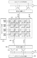
図4は、CMOSセンサにおける画素信号の読み出しに必要な回路構成を示した図である。図4に示すように、左眼用受光素子201及び右眼用受光素子202それぞれの出力は、異なる読み出し回路に接続されている。なお、単位画素は、上述したように左眼用受光素子201及び右眼用受光素子202で構成されるため、破線で示されており、図の例では簡単のため、横2列、縦4行の8画素を備える撮像素子を示している。
FIG. 4 is a diagram showing a circuit configuration necessary for reading pixel signals in the CMOS sensor. As shown in FIG. 4, the outputs of the left-eye
ここでは、右眼用の画素信号の読み出しについて以下に説明する。なお、左眼用の画素信号の読み出しについても、読み出し回路(CH1)が同様に行うものとする。 Here, reading of the pixel signal for the right eye will be described below. Note that the readout circuit (CH1) similarly performs readout of the pixel signal for the left eye.
垂直シフトレジスタ401は、TG105より入力されたタイミング信号に応じて、行選択線(垂直走査線)Pres、Ptx、及びPselを介して、信号電圧を左眼用受光素子201及び右眼用受光素子202に印加する。各受光素子において、転送MOSトランジスタ302のゲートは行選択線Ptxに、リセットMOSトランジスタ303のゲートは行選択線Presに、選択MOSトランジスタ305のゲートは行選択線Pselに接続されている。このように、同一行の受光素子は同一の垂直走査線に共通接続されている。また、各受光素子の選択MOSトランジスタ305のソースは、垂直方向に延長して配置される垂直信号線の端子Voutに接続され、負荷手段である定電流源407に接続される。
The
そして、各受光素子の出力は、当該垂直信号線を介して読み出し回路402により読み出される。読み出し回路402は、入力である垂直信号線上の画素信号のうち、画素信号をnチャネルMOSトランジスタ403に、ノイズ信号をnチャネルMOSトランジスタ404に出力する。そしてそれぞれのnチャネルMOSトランジスタに出力された信号は差動増幅器405に入力され、画素信号とノイズ信号の差分がアナログ画像信号として出力される。なお、読み出し回路402は、列ごとの読み出し回路を含んでいる。また水平シフトレジスタ406は、nチャネルMOSトランジスタ403及びnチャネルMOSトランジスタ404のON/OFFを制御する。
The output of each light receiving element is read out by the
このように、本実施形態の撮像部106は1画素中に1対の受光素子を備え、射出瞳の異なる領域を通過した光束により、左眼用及び右眼用の画像を取得し、アナログフロントエンド(AFE)107に出力する。
As described above, the
AFE107は、TG105より入力されたタイミング信号に従い、入力されたアナログ画像信号について信号増幅、及びA/D変換処理等を行ない、左眼用及び右眼用の画像データを出力する。
The
DSP(Digital Signal Processor)108は、入力された画像データについて、色変換やホワイトバランス調整等の補正処理、及び予め定められた記録形式への符号化処理等を実行する画像処理回路である。 A DSP (Digital Signal Processor) 108 is an image processing circuit that executes correction processing such as color conversion and white balance adjustment on input image data, encoding processing into a predetermined recording format, and the like.
測光回路109は、被写体輝度を測定するための回路であり、当該回路により取得された被写体輝度の情報は、通常の画像撮影における絞り値の決定、及び露出量の決定に用いられる。
The
表示部110は、例えば小型LCD等のデジタルカメラ100が備える表示装置であり、撮影された画像、及び後述する記録媒体に記録されている画像の表示に用いられる。本実施形態では、表示部110はユーザが裸眼立体視可能なように左眼用及び右眼用画像を表示する表示装置であるものとする。また、撮像部106により撮像されたアナログ画像信号を順次表示部110に出力することにより、表示部110は電子ビューファインダとして機能する。
The
記録媒体111は、例えばデジタルカメラ100が備える内蔵メモリや、メモリカードやHDD等のデジタルカメラ100に着脱可能に接続される記録装置である。デジタルカメラ100において撮影された画像は、所定の符号化形式に変換された後、当該記録媒体111に記録されるものとする。
The
操作部112は、例えば電源ボタン、シャッタボタン、モード切替スイッチ等のデジタルカメラ100が備えるユーザインタフェースである。操作部112は、ユーザにより各操作部材が操作されたことに応じて、操作内容を示す制御信号をCPU101に出力する。
The
<視差拡張の概念>
ここで、本発明における、射出瞳の異なる領域を通過した光束により得られる両眼立体視用の画像における視差を拡張する方法の概念について、図5を用いて説明する。
<Concept of parallax expansion>
Here, the concept of the method for extending the parallax in the binocular stereoscopic image obtained by the light flux that has passed through different areas of the exit pupil in the present invention will be described with reference to FIG.
例えば、撮像光学系104の絞りが開放状態である場合、左眼用受光素子501及び右眼用受光素子502に結像される光学像は、図5(a)のように射出瞳503において異なる領域504及び505のそれぞれを通過した光束である。このときの光束の入射角に対する強度分布は、図11を参照して前述したように図5(d)のようになり、当該光束により得られた両眼立体視用の画像における視差は、開放絞り時の射出瞳の半径L1に応じて決定される。
For example, when the aperture of the imaging
また、撮像光学系104の絞りが絞り状態である場合、左眼用受光素子501及び右眼用受光素子502に結像される光学像は図5(b)のように、射出瞳503より狭められた射出瞳511において、異なる領域512及び513のそれぞれを通過した光束である。このとき、光束の入射角に対する強度分布は、図5(e)のようになり、当該光束により得られた両眼立体視用の画像における視差は、絞り状態の射出瞳の半径L2(L2<L1)に応じて決定される。
When the aperture of the imaging
本発明では、このように絞り状態を異ならせて得られた左眼用及び右眼用の画像データの画素値を減算することにより、図5(c)のような領域521及び522を通過した光束により結像された光学像に相当する画像データを取得する。即ち、当該減算により光束の入射角に対する強度分布は図5(f)のようになり、レンズ外周からの光に対して相対的に感度が高くなるため、射出瞳における光束の通過領域の重心間距離L3を、絞り開放状態における重心間距離より拡張することができる。つまり、当該重心間距離に応じて決定される左眼用及び右眼用の画像における視差を、拡張することができる。
In the present invention, the pixel values of the left-eye and right-eye image data obtained by changing the aperture state in this way are subtracted to pass through the
なお、絞り径と射出瞳の径が一致する撮像光学系の場合、 図5(a)乃至(c)に示した左眼用及び右眼用の受光素子に到達する光束が、射出瞳において通過する領域の重心間距離L1、L2、及びL3は、概略以下のようになる。
L1=D1/2
L2=D2/2
L3=L1+L2
ここで、D1は開放絞り時の絞り径、D2は絞り状態における絞り径である。
Note that in the case of an imaging optical system in which the aperture diameter and the exit pupil diameter match, the light beams reaching the left-eye and right-eye light receiving elements shown in FIGS. 5A to 5C pass through the exit pupil. The distances L1, L2, and L3 between the centers of gravity of the regions to be processed are as follows.
L1 = D1 / 2
L2 = D2 / 2
L3 = L1 + L2
Here, D1 is the aperture diameter when the aperture is fully open, and D2 is the aperture diameter in the aperture state.
また、図5(b)の場合における左眼用受光素子501及び右眼用受光素子502の出力Pbは、撮像光学系104の光学性能や、撮像部106のマイクロレンズ及び受光素子の配置に起因する集光性能により変化するが、絞り開放状態における出力Paを基準として
Pa×(D2/D1)≦Pb≦Pa×(D2/D1)2
の範囲に含まれる。またこの場合、視差を拡張するために減算した画像データにおける出力Pcは、
Pc=Pa−Pb
となる。
In addition, the output Pb of the left-eye
Included in the range. Also in this case, the output P c in the image data subtracted to extend the parallax is
P c = P a −P b
It becomes.
なお、絞りの開口はステッピングモータ等の駆動系により段階的に制御されるため、開放状態で得られた左眼用及び右眼用の画像データから、絞り状態で得られた左眼用および右眼用の画像データを減算しても、所望の視差を有する画像を得られないことがある。この場合、例えば図6に示すような、異なる絞り状態で得られた画像データを減算することにより、所望の視差を有する両眼立体視用の画像を取得するようにしてもよい。 Since the aperture of the aperture is controlled step by step by a drive system such as a stepping motor, the left and right eyes obtained in the aperture state are obtained from the left-eye and right-eye image data obtained in the open state. Even if the image data for eyes is subtracted, an image having a desired parallax may not be obtained. In this case, for example, a binocular stereoscopic image having a desired parallax may be acquired by subtracting image data obtained in different aperture states as shown in FIG.
両眼立体視用の画像が所望の視差となるように選択される2つの絞り値の組み合わせは、上述したようにCPU101は計算により算出してもよい。また、所望の視差となるように撮影を行う2つの絞り値の組み合わせの情報は、例えばROM102に予め記憶されていてもよい。このようにすることで、CPU101は設定された視差を有する両眼立体視用の画像を取得するために撮影する2種類の絞り値を決定することが可能となる。
As described above, the
なお、2つの絞り値の組み合わせは、所望される視差によって次のような傾向になる。即ち、大きい視差が要求される場合、より外側から入射する光束を取り込むために、開側の絞りの開口はより大きくなるように絞り値が決定される。また、減算後の画像データに対応する光束が射出瞳において通過する領域の重心間距離を大きくするために、閉側の絞りの開口はより開側の絞りの開口に近づく、即ち開側の絞りの開口と閉側の絞りの開口との差が小さくなるように絞り値が決定される。このように、本発明を用いることにより、射出瞳の異なる領域を通過した光束により得られる左眼用及び右眼用の画像データにおける視差は、理論的には略射出瞳の径に近い値まで拡張することができる。 The combination of the two aperture values has the following tendency depending on the desired parallax. That is, when a large parallax is required, the aperture value is determined so that the aperture of the aperture on the open side becomes larger in order to capture a light beam incident from the outside. Further, in order to increase the distance between the centers of gravity of the areas where the light flux corresponding to the image data after the subtraction passes through the exit pupil, the aperture of the closed side is closer to the aperture of the open side, that is, the aperture of the open side The aperture value is determined so as to reduce the difference between the aperture of the aperture and the aperture of the aperture on the closed side. Thus, by using the present invention, the parallax in the left-eye and right-eye image data obtained by the light flux that has passed through different regions of the exit pupil is theoretically close to a value close to the diameter of the exit pupil. Can be extended.
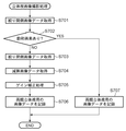
<立体視画像撮影処理>
このような構成をもつ本実施形態のデジタルカメラ100の立体視画像撮影処理について、図7のフローチャートを用いて具体的な処理を説明する。当該フローチャートに対応する処理は、CPU101が、例えばROM102に記憶されている対応する処理プログラムを読み出し、RAM103に展開して実行することにより実現することができる。なお、本立体視画像撮影処理は、例えばデジタルカメラ100の撮影モードが、視差が大きい両眼立体視用の画像を撮影する視差強調モードに設定された状態で、ユーザのシャッタボタン操作により撮影指示が入力された際に開始されるものとして説明する。即ち、本立体視画像撮影処理により得られる両眼立体視用の画像は、当該画像における左眼用及び右眼用の画像の視差が、通常開放絞り状態で得られる画像よりも拡張されているものとする。
<Stereoscopic image shooting processing>
A specific process of the stereoscopic image shooting process of the
S701で、CPU101は、絞り値を例えばF2.0等の開側の値(第1の絞り値)に設定して撮影処理を実行し、得られた絞り開側画像データをRAM103に格納する。なお、上述したように絞り開側画像データは左眼用及び右眼用の画像データで構成される。
In step S <b> 701, the
S702で、CPU101は、S701で撮影された絞り開側画像データの左眼用及び右眼用の画像データに飽和画素が含まれているか否かを判断する。具体的にはCPU101は、左眼用及び右眼用それぞれの画像データの各画素の画素値を取得し、最大値を示す画素が存在するか否かを判断する。CPU101は、絞り開側画像データの左眼用及び右眼用の画像データに飽和画素が含まれていると判断した場合は処理をS707に移し、含まれていないと判断した場合は処理をS703に移す。
In step S <b> 702, the
飽和画素が存在する場合、異なる絞り値で撮影された画像データと減算を行ったとしても、対応する射出瞳の領域を通過した光束により得られる画像データとは厳密には異なる。このため、本立体視画像撮影処理において飽和画素が存在した場合は、視差の拡張ができないと判断し、後述するS707において絞り開側画像データを両眼立体視用の画像として記録媒体111に記録する。
When there is a saturated pixel, even if subtraction is performed on image data captured with a different aperture value, the image data obtained from the light beam that has passed through the corresponding exit pupil region is strictly different. For this reason, if there is a saturated pixel in the stereoscopic image capturing process, it is determined that the parallax cannot be expanded, and the aperture opening side image data is recorded in the
S703で、CPU101は、絞り値を例えばF8.0等の閉側の値(第2の絞り値)に設定し、絞り開側画像データの撮影時と同一の露光時間で撮影処理を行い、得られた絞り閉側画像データをRAM103に格納する。即ち、同一の露光時間で撮影を行うことにより、飽和信号の発生を回避するとともに、絞り開側画像データと絞り閉側画像データの減算を行った際に、適切に絞り閉側画像データに対応する光束の成分を除去した画像データを得ることができる。
In step S <b> 703, the
S704で、CPU101は、左眼用及び右眼用それぞれの画像データについて、絞り開側画像データと絞り閉側画像データとの減算をDSP108に実行させる。例えばDSP108は、RAM103に記憶されているそれぞれの画像データを読み出し、左眼用及び右眼用の画像データについて画素値の減算を行った後、得られた画像データをRAM103に格納する。
In step S <b> 704, the
S705で、CPU101は、画素値の減算により画像の平均輝度が低下するため、当該減算により低下した平均輝度を補償するようにゲイン補正処理をDSP108に実行させる。このとき、ゲイン補正量gは、絞り開側の絞り径をd1、絞り閉側の絞り径をd2とした場合、概略
g=(d1/(d1−d2))2
となる。しかしながら、当該ゲイン補正量は上述したように撮像光学系の光学性能等に起因して変化するため、予め実験的に求められていてもよい。
In step S <b> 705, the
It becomes. However, since the gain correction amount changes due to the optical performance of the imaging optical system as described above, it may be obtained experimentally in advance.
また、絞り開側画像データと絞り閉側画像データとでは絞り径(開口状態)が異なるため、周辺光量落ちの特性(周辺画素における信号レベルの減衰率)が異なる。このため、ゲイン補正処理は、当該周辺光量落ち特性を他方の画像データに合わせるように補正する処理も含む。例えば、絞り値のそれぞれについて予め周辺光量落ちの特性を実験的に測定しておき、選択された2種類の絞り値に対して、当該周辺光量落ちの差分を取得し、一方に対して適用すればよい。このようにして周辺光量落ち特性を合わせた画像を用いて減算を行うことにより、周辺画素においても適切な減算結果を得ることができる。 Further, since the aperture diameter (opening state) is different between the aperture open side image data and the aperture close side image data, the peripheral light amount drop characteristics (signal level attenuation rate in the peripheral pixels) are different. For this reason, the gain correction processing includes processing for correcting the peripheral light amount drop characteristic so as to match the other image data. For example, the peripheral light amount drop characteristic is experimentally measured in advance for each of the aperture values, and the difference in the peripheral light amount drop is obtained for the two selected aperture values and applied to one of them. That's fine. In this way, by performing subtraction using an image combined with the peripheral light amount drop characteristic, an appropriate subtraction result can be obtained even in the peripheral pixels.
S706で、CPU101はDSP108に、ゲイン補正がなされた左眼用及び右眼用の画像データを、予め定められた両眼立体視用の画像データの記録形式に変換させる。そしてCPU101は得られた記録形式の両眼立体視用の画像データを記録媒体111に記録し、本立体視用画像撮影処理を完了する。
In step S <b> 706, the
またS702において絞り開側画像データに飽和画素が含まれていると判断された場合、CPU101はS707において、DSP108に当該絞り開側画像データを予め定められた両眼立体視用の画像データの記録形式に変換させる。そしてCPU101は、得られた記録形式の両眼立体視用の画像データを記録媒体111に記録し、本立体視用画像処理を完了する。
If it is determined in step S702 that the aperture-open side image data includes a saturated pixel, the
なお、S702において、絞り開側画像データに飽和画素があった場合は、絞り閉側画像データの撮影を行わずに当該絞り開側画像データを用いて両眼立体視用の画像データを生成するものとして説明したが、本発明の実施はこれに限らない。例えば、飽和画素がなくなるような露光時間を設定し、当該露光時間を用いて再度絞り開側画像データの撮影処理を実行してもよい。 If there is a saturated pixel in the aperture open side image data in S702, binocular stereoscopic image data is generated using the aperture open side image data without capturing the aperture closed side image data. Although described as a thing, implementation of this invention is not restricted to this. For example, an exposure time that eliminates saturated pixels may be set, and the aperture opening side image data shooting process may be executed again using the exposure time.
以上説明したように、本実施形態の撮像装置は、射出瞳の異なる領域を通過した光束により得られる両眼立体視用の画像における視差を拡張することができる。具体的には撮像装置は、絞りを含む撮像光学系と、各々が左眼用及び右眼用の受光素子を備える複数の画素からなり、左眼用及び右眼用の受光素子のそれぞれが左眼用及び右眼用の画像を出力する撮像素子とを備える。そして、左眼用及び右眼用の画像の各々について、絞りの開口が開側の状態である際に撮像素子により出力された第1の画像の画素値から、絞りの開口が閉側の状態である際に撮像素子により出力された第2の画像の画素値を減算することにより得られた第3の画像を両眼立体視用の画像データとして出力する。このとき、第3の画像データは、例えば図5における左眼用画素501から得られた左眼用画像と右眼用画素502から得られた右眼用画像を1つのシーンとして別々に記録する。再生装置では前記1つのシーンとして記録された左眼用画像を左眼で視認し右眼用画像を右眼で視認出来るように再生することで、撮影された画像を立体視することが可能である。
As described above, the imaging apparatus of the present embodiment can expand the parallax in the binocular stereoscopic image obtained by the light flux that has passed through different areas of the exit pupil. Specifically, the imaging apparatus includes an imaging optical system including a diaphragm and a plurality of pixels each including a left-eye and right-eye light receiving elements, and each of the left-eye and right-eye light receiving elements is left. An imaging device that outputs images for the eyes and the right eye. Then, for each of the left-eye and right-eye images, the aperture opening is in the closed state from the pixel value of the first image output by the image sensor when the aperture opening is in the open state. In this case, the third image obtained by subtracting the pixel value of the second image output by the image sensor is output as binocular stereoscopic image data. At this time, as the third image data, for example, the left-eye image obtained from the left-
このようにすることで、単眼の撮像装置であっても、二眼の撮像装置と同様の視差を有する画像を取得することもできるため、ユーザに対して効果的に視差を調整した画像を提示することができる。 In this way, even with a monocular imaging device, an image having the same parallax as that of a binocular imaging device can be acquired, so an image with effectively adjusted parallax is presented to the user. can do.
[変形例]
上述した実施形態では、視差強調モードのみの動作について説明したが、デジタルカメラ100が通常の撮影モード、及び撮影する両眼立体視用の画像について異なる視差を設定可能なモードを備える場合の例について説明する。
[Modification]
In the above-described embodiment, the operation only in the parallax enhancement mode has been described. However, an example in which the
<撮影処理>
上述の実施形態1と同様の構成を有する本変形例のデジタルカメラ100の撮影処理について、図8のフローチャートを用いて具体的な処理を説明する。当該フローチャートに対応する処理は、CPU101が、例えばROM102に記憶されている対応する処理プログラムを読み出し、RAM103に展開して実行することにより実現することができる。なお、本撮影処理は、例えばデジタルカメラ100が撮影可能なモードに設定されている状態で、ユーザがシャッタボタンを操作することにより撮影指示が入力された際に開始されるものとして説明する。
<Shooting process>
A specific process of the photographing process of the
S801で、CPU101は、現在のデジタルカメラ100の撮影モードが両眼立体視用の画像データの撮影を行うモードに設定されているか否かを判断する。具体的にはCPU101は、例えばRAM103に格納されている現在の撮影モードの設定が、視差強調モード、視差低減モード、及び通常視差モードのいずれかに該当するか否かを判断する。なお、本実施形態で説明する両眼立体視用の画像データの撮影を行うモードの概要は、以下のようになる。
In step S <b> 801, the
・通常視差モード:絞り開放状態(例えばF2.0)で得られた画像を両眼立体視用の画
像データとして記録するモード
・視差低減モード:通常視差モードよりも視差の小さい両眼立体視用の画像データを記録
するモード(例えば、絞り開放より6段絞ったF16と、7段絞った
F22とで得られた画像データの減算を行う)
・視差強調モード:通常視差モードよりも視差の大きい両眼立体視用の画像データを記録
するモード(例えば、絞り開放F2.0と、絞り開放より1段絞った
F2.8とで得られた画像データの減算を行う)
Normal parallax mode: Binocular stereoscopic images obtained with the aperture fully open (eg, F2.0)
Mode for recording as image data / Parallax reduction mode: Records binocular stereoscopic image data with a smaller parallax than the normal parallax mode
Mode (for example, F16, which is 6 stops from the fully open position, and 7 stops)
Subtract the image data obtained in F22)
-Parallax enhancement mode: Records binocular stereoscopic image data with a larger parallax than the normal parallax mode
Mode (for example, full aperture F2.0, one stop from full aperture)
(Subtract the image data obtained in F2.8)
CPU101は、現在のデジタルカメラ100の撮影モードが両眼立体視用の画像データの撮影を行うモードに設定されていると判断した場合は処理をS803に移し、それ以外の撮影モードに設定されていると判断した場合は処理をS802に移す。
When the
S802で、CPU101は、測光回路109により決定された露光量に従って通常のAE撮影を行い、DSP108に得られた画像データを記録形式に変換させ、記録媒体111に記録し、本撮影処理を完了する。
In step S <b> 802, the
また両眼立体視用の画像データの撮影を行うモードに設定されていると判断した場合、CPU101はS803で、現在の撮影モードが視差強調モードであるか否かを判断する。CPU101は、現在の撮影モードが視差強調モードであると判断した場合は処理をS804に移し、視差強調モードではないと判断した場合は処理をS805に移す。
If the
S804で、CPU101は、上述した実施形態の立体視画像撮影処理と同様に、F2.0とF2.8について撮影を行い、左眼用及び右眼用それぞれの画像データを減算して記録用の両眼立体視用の画像データを取得し、記録媒体111に記録する。
In step S804, the
S805で、CPU101は、現在の撮影モードが視差低減モードであるか否かを判断する。CPU101は、現在の撮影モードが視差低減モードであると判断した場合は処理をS806に移し、視差低減モードではないと判断した場合は処理をS807に移す。
In step S805, the
S806で、CPU101は、上述した実施形態の立体視画像撮影処理と同様に、F16とF22について撮影を行い、左眼用及び右眼用それぞれの画像データを減算して記録用の両眼立体視用の画像データを取得し、記録媒体111に記録する。
In step S806, the
S805において現在の撮影モードが視差低減モードではないと判断した場合、CPU101は現在の撮影モードは通常視差モードであると判断する。そしてCPU101は、S807においてF2.0で撮影を行い、得られた左眼用及び右眼用の画像データをDSP108に記録形式の両眼立体視用の画像データに変換させ、記録媒体111に記録する。
When determining in step S805 that the current shooting mode is not the parallax reduction mode, the
なお、本実施形態では撮影モードによって3段階に視差を切り替えて両眼立体視用の画像データを撮影可能であるものとして説明したが、本発明の実施はこれに限らない。例えば、ユーザにより選択された視差の目標値について、絞り値の変更で対応可能か、あるいは異なる2つの絞り値の組み合わせを選択して、得られた2つの画像の画素値の減算を行うかを判断して撮影処理を行ってもよい。 Although the present embodiment has been described on the assumption that binocular stereoscopic image data can be captured by switching parallax in three stages depending on the shooting mode, the present invention is not limited to this. For example, whether the parallax target value selected by the user can be dealt with by changing the aperture value or whether a combination of two different aperture values is selected and the pixel values of the two obtained images are subtracted. Judgment processing may be performed after determination.
このようにすることで、両眼立体視用の画像データを撮影する際に、ユーザはシーンに合わせて所望の視差を選択することができる。また、撮像光学系の射出瞳に制限されず、視差の選択について自由度を向上させることができる。 In this way, when shooting binocular stereoscopic image data, the user can select a desired parallax according to the scene. Further, the degree of freedom in selecting parallax can be improved without being limited to the exit pupil of the imaging optical system.
なお、上述した実施形態及び変形例は、異なる2つの絞り状態で撮影して得られた、左眼用及び右眼用の画像を減算することにより、両眼立体視用の画像における視差を拡張する方法について説明したが、本発明の実施はこれに限らない。 In the above-described embodiment and the modification, the parallax in the binocular stereoscopic image is expanded by subtracting the left-eye image and the right-eye image obtained by photographing with two different aperture states. Although the method to do was demonstrated, implementation of this invention is not restricted to this.
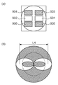
本発明のように単位画素内に複数の受光素子を設ける場合、受光素子の各々について読み出し回路が必要になる。このため、読み出し回路の設置スペースを確保すると、例えば図9(a)に示すように受光素子の受光面積は限定されることが考えられる。しかしながら図9(a)のように、撮像素子において、垂直方向に左眼用及び右眼用の受光素子901及び902の占有範囲を狭めることにより得られた画像データを用いて、上述の処理を行うことにより同様の効果を得ることができる。即ち、単位画素において受光可能な光束が制限されたとしても、異なる絞り開口で得られた画素信号の差分に対応する射出瞳の領域は図9(b)のように垂直方向にのみ縮小されるため、当該領域の重心位置は受光面積に依らず変化しない。つまり、上述した実施形態及び変形例と同様に、視差をより拡張することが可能である。
When a plurality of light receiving elements are provided in a unit pixel as in the present invention, a readout circuit is required for each of the light receiving elements. For this reason, if the installation space for the readout circuit is secured, it is conceivable that the light receiving area of the light receiving element is limited, for example, as shown in FIG. However, as shown in FIG. 9A, in the imaging device, the above processing is performed using image data obtained by narrowing the occupation range of the left-eye and right-eye light-receiving
なお、図9(a)の例では、受光素子の構成要素を効率的に配置するために、それぞれの受光素子であるフォトダイオードに接続される転送MOSトランジスタ903及び904とリセットMOSトランジスタ905及び906とが配置されている。このとき、受光素子901及び902以外の部材については、光が入射しないように直上に金属遮光層が配置されているものとする。
In the example of FIG. 9A,
また例えば上述したような、透過型の液晶等を絞りとして用いることで、異なる2つの絞り値で撮影された画像データの画素値を減算することなく、当該絞りにより射出瞳を通過する領域を制御することも可能である。具体的には例えば図10(a)に示すような絞りを用いることで視差を拡張する、あるいは図10(b)に示すような絞りを用いることで視差を低減することが容易に実現できる。 Further, for example, by using a transmissive liquid crystal or the like as described above, the region passing through the exit pupil is controlled by the aperture without subtracting the pixel value of the image data photographed at two different aperture values. It is also possible to do. Specifically, for example, the parallax can be easily extended by using a diaphragm as shown in FIG. 10A, or the parallax can be easily reduced by using a diaphragm as shown in FIG.
(その他の実施形態)
また、本発明は、以下の処理を実行することによっても実現される。即ち、上述した実施形態の機能を実現するソフトウェア(プログラム)を、ネットワーク又は各種記憶媒体を介してシステム或いは装置に供給し、そのシステム或いは装置のコンピュータ(またはCPUやMPU等)がプログラムを読み出して実行する処理である。
(Other embodiments)
The present invention can also be realized by executing the following processing. That is, software (program) that realizes the functions of the above-described embodiments is supplied to a system or apparatus via a network or various storage media, and a computer (or CPU, MPU, or the like) of the system or apparatus reads the program. It is a process to be executed.
Claims (12)
左眼用及び右眼用の画像における視差が変化するよう前記絞りの開口を制御する制御手段と、
前記撮像素子により出力された左眼用及び右眼用の画像を用いて、両眼立体視用の画像を生成する生成手段と、を備え、
前記生成手段は、左眼用及び右眼用の画像における視差が異なる第1の状態及び第2の状態の各々について撮像された左眼用及び右眼用の画像各々の画素値を状態間で減算することにより、何れかの状態の左眼用及び右眼用の画像より視差を拡張した前記両眼立体視用の画像を生成する
ことを特徴とする撮像装置。 An image sensor that includes light-receiving elements for the left eye and the right eye , converts light beams that have passed through the same imaging optical system having a diaphragm, and outputs images for the left eye and the right eye;
And control means for controlling the pre Kishibo Rino opening so that parallax is changed in the image for the left eye and right eye,
Generating means for generating a binocular stereoscopic image using the left-eye and right-eye images output by the imaging device;
The generating means calculates the pixel values of the left-eye and right-eye images captured for each of the first state and the second state in which the parallax in the left-eye and right-eye images is different between the states. An image pickup apparatus that generates the binocular stereoscopic image in which the parallax is expanded from the left-eye image and the right-eye image in any state by performing subtraction .
前記生成手段は、前記第1の状態について撮像された左眼用及び右眼用の画像各々の画素値から、前記第2の状態について撮像された左眼用及び右眼用の画像各々の画素値を減算することにより前記両眼立体視用の画像を出力する
ことを特徴とする請求項1に記載の撮像装置。 The second state is a state where the parallax in the left-eye and right-eye images is smaller than the first state,
The generating means uses each pixel value of the left-eye image and the right-eye image captured in the first state based on the pixel value of each of the left-eye image and the right-eye image captured in the first state. The imaging apparatus according to claim 1, wherein the image for binocular stereoscopic vision is output by subtracting a value.
前記制御手段は、前記設定手段により設定された視差が大きいほど、前記第1の状態の左眼用及び右眼用の画像における視差と前記第2の状態の左眼用及び右眼用の画像における視差との差が小さくなるように、前記第1の状態及び前記第2の状態における前記絞りの開口を制御することを特徴とする請求項1乃至7のいずれか1項に記載の撮像装置。 A setting unit for setting a parallax generated by the binocular stereoscopic image output by the generation unit;
Wherein, the larger the parallax set by the setting means, the first state of the left eye and the image for the left eye and the right eye of the second state the parallax of the image for the right eye 8. The imaging apparatus according to claim 1, wherein an aperture of the diaphragm in the first state and the second state is controlled so that a difference from the parallax in the second state is small. .
制御手段が、左眼用及び右眼用の画像における視差が変化するよう前記絞りの開口を制御する制御工程と、
生成手段が、前記撮像素子により出力された左眼用及び右眼用の画像を用いて、両眼立体視用の画像を生成する生成工程と、を備え、
前記生成手段は前記生成工程において、左眼用及び右眼用の画像における視差が異なる第1の状態及び第2の状態の各々について撮像された左眼用及び右眼用の画像各々の画素値を状態間で減算することにより、何れかの状態の左眼用及び右眼用の画像より視差を拡張した前記両眼立体視用の画像を生成する
ことを特徴とする撮像装置の制御方法。 Control method for an image pickup apparatus including left-eye and right-eye light-receiving elements, and an image sensor that converts a light beam that has passed through the same imaging optical system having a diaphragm and outputs left-eye and right-eye images Because
Control means, and a control step of controlling the pre Kishibo Rino opening such that the parallax of the image of the left-eye and right-eye changes,
A generating unit that generates a binocular stereoscopic image using the left-eye and right-eye images output by the imaging device; and
In the generating step, the generating means includes pixel values of each of the left-eye and right-eye images captured in each of the first state and the second state in which parallaxes in the left-eye and right-eye images are different. A method for controlling an imaging apparatus, wherein the binocular stereoscopic image in which the parallax is expanded from the left-eye image and the right-eye image in any state is generated by subtracting between the states .
Priority Applications (1)
| Application Number | Priority Date | Filing Date | Title |
|---|---|---|---|
| JP2011193273A JP5860251B2 (en) | 2011-09-05 | 2011-09-05 | Imaging apparatus, control method therefor, and program |
Applications Claiming Priority (1)
| Application Number | Priority Date | Filing Date | Title |
|---|---|---|---|
| JP2011193273A JP5860251B2 (en) | 2011-09-05 | 2011-09-05 | Imaging apparatus, control method therefor, and program |
Publications (3)
| Publication Number | Publication Date |
|---|---|
| JP2013055560A JP2013055560A (en) | 2013-03-21 |
| JP2013055560A5 JP2013055560A5 (en) | 2014-10-16 |
| JP5860251B2 true JP5860251B2 (en) | 2016-02-16 |
Family
ID=48132168
Family Applications (1)
| Application Number | Title | Priority Date | Filing Date |
|---|---|---|---|
| JP2011193273A Expired - Fee Related JP5860251B2 (en) | 2011-09-05 | 2011-09-05 | Imaging apparatus, control method therefor, and program |
Country Status (1)
| Country | Link |
|---|---|
| JP (1) | JP5860251B2 (en) |
Families Citing this family (2)
| Publication number | Priority date | Publication date | Assignee | Title |
|---|---|---|---|---|
| JP5887845B2 (en) * | 2011-11-09 | 2016-03-16 | 株式会社ニコン | Image processing method and image processing program |
| JP6145836B2 (en) * | 2012-12-04 | 2017-06-14 | パナソニックIpマネジメント株式会社 | Stereo camera |
Family Cites Families (2)
| Publication number | Priority date | Publication date | Assignee | Title |
|---|---|---|---|---|
| JP2001061165A (en) * | 1999-08-20 | 2001-03-06 | Sony Corp | Lens device and camera |
| JP3869702B2 (en) * | 2001-10-30 | 2007-01-17 | ペンタックス株式会社 | Stereo image pickup device |
-
2011
- 2011-09-05 JP JP2011193273A patent/JP5860251B2/en not_active Expired - Fee Related
Also Published As
| Publication number | Publication date |
|---|---|
| JP2013055560A (en) | 2013-03-21 |
Similar Documents
| Publication | Publication Date | Title |
|---|---|---|
| US9258545B2 (en) | Stereoscopic imaging apparatus | |
| US10511781B2 (en) | Image pickup apparatus, control method for image pickup apparatus | |
| JP5502205B2 (en) | Stereo imaging device and stereo imaging method | |
| JP5469258B2 (en) | Imaging apparatus and imaging method | |
| WO2012002307A1 (en) | Single-lens stereoscopic image capture device | |
| JP2011101240A (en) | Stereoscopic photographing device and photographing control method | |
| JP2012063396A (en) | Focus adjustment device | |
| JP6530593B2 (en) | Imaging device, control method therefor, storage medium | |
| JP2010154310A (en) | Compound-eye camera, and photographing method | |
| JP2005092085A (en) | Focus detecting method and focusing method, and focus detecting device and focusing device | |
| US9288478B2 (en) | Image pickup apparatus that determines shooting composition, method of controlling the same, and storage medium | |
| CN115103141A (en) | Imaging element and imaging device | |
| WO2013035427A1 (en) | Stereoscopic image capture device and method | |
| US10097751B2 (en) | Imaging apparatus and image compositing method | |
| JP2014036362A (en) | Imaging device, control method therefor, and control program | |
| US11171169B2 (en) | Image sensor, imaging device and imaging method | |
| US9106900B2 (en) | Stereoscopic imaging device and stereoscopic imaging method | |
| JP5860251B2 (en) | Imaging apparatus, control method therefor, and program | |
| JP5457240B2 (en) | Stereo imaging device | |
| US11463613B2 (en) | Detection device and detection method | |
| JP2013046395A (en) | Image capturing apparatus, control method therefor, program, and recording medium | |
| JP2018191223A (en) | Imaging apparatus and control method for imaging device | |
| JP2023116360A (en) | Control unit, electronic apparatus, control method, and program | |
| JP2019062537A (en) | Imaging apparatus and control method thereof, program, storage medium | |
| JP2018164150A (en) | Imaging apparatus, image processing device and image processing system |
Legal Events
| Date | Code | Title | Description |
|---|---|---|---|
| A521 | Request for written amendment filed |
Free format text: JAPANESE INTERMEDIATE CODE: A523 Effective date: 20140903 |
|
| A621 | Written request for application examination |
Free format text: JAPANESE INTERMEDIATE CODE: A621 Effective date: 20140903 |
|
| A977 | Report on retrieval |
Free format text: JAPANESE INTERMEDIATE CODE: A971007 Effective date: 20150410 |
|
| A131 | Notification of reasons for refusal |
Free format text: JAPANESE INTERMEDIATE CODE: A131 Effective date: 20150417 |
|
| A521 | Request for written amendment filed |
Free format text: JAPANESE INTERMEDIATE CODE: A523 Effective date: 20150615 |
|
| TRDD | Decision of grant or rejection written | ||
| A01 | Written decision to grant a patent or to grant a registration (utility model) |
Free format text: JAPANESE INTERMEDIATE CODE: A01 Effective date: 20151120 |
|
| A61 | First payment of annual fees (during grant procedure) |
Free format text: JAPANESE INTERMEDIATE CODE: A61 Effective date: 20151218 |
|
| R151 | Written notification of patent or utility model registration |
Ref document number: 5860251 Country of ref document: JP Free format text: JAPANESE INTERMEDIATE CODE: R151 |
|
| LAPS | Cancellation because of no payment of annual fees |