JP5885416B2 - IMAGING DEVICE AND IMAGING DEVICE CONTROL METHOD - Google Patents
IMAGING DEVICE AND IMAGING DEVICE CONTROL METHOD Download PDFInfo
- Publication number
- JP5885416B2 JP5885416B2 JP2011155908A JP2011155908A JP5885416B2 JP 5885416 B2 JP5885416 B2 JP 5885416B2 JP 2011155908 A JP2011155908 A JP 2011155908A JP 2011155908 A JP2011155908 A JP 2011155908A JP 5885416 B2 JP5885416 B2 JP 5885416B2
- Authority
- JP
- Japan
- Prior art keywords
- value
- predetermined range
- output value
- block
- predetermined
- Prior art date
- Legal status (The legal status is an assumption and is not a legal conclusion. Google has not performed a legal analysis and makes no representation as to the accuracy of the status listed.)
- Expired - Fee Related
Links
- 238000003384 imaging method Methods 0.000 title claims description 42
- 238000000034 method Methods 0.000 title claims description 33
- PCHJSUWPFVWCPO-UHFFFAOYSA-N gold Chemical compound [Au] PCHJSUWPFVWCPO-UHFFFAOYSA-N 0.000 claims description 3
- 239000010931 gold Substances 0.000 claims description 3
- 229910052737 gold Inorganic materials 0.000 claims description 3
- 238000012545 processing Methods 0.000 description 51
- 230000015654 memory Effects 0.000 description 25
- 230000008569 process Effects 0.000 description 18
- 230000006870 function Effects 0.000 description 11
- 238000005259 measurement Methods 0.000 description 10
- 230000003595 spectral effect Effects 0.000 description 7
- 238000006243 chemical reaction Methods 0.000 description 5
- 238000004891 communication Methods 0.000 description 4
- 238000010586 diagram Methods 0.000 description 3
- 238000000605 extraction Methods 0.000 description 3
- 230000003287 optical effect Effects 0.000 description 3
- 238000005375 photometry Methods 0.000 description 3
- 238000002310 reflectometry Methods 0.000 description 3
- 238000009825 accumulation Methods 0.000 description 2
- 238000012937 correction Methods 0.000 description 2
- 238000001514 detection method Methods 0.000 description 2
- 238000012935 Averaging Methods 0.000 description 1
- 238000004458 analytical method Methods 0.000 description 1
- 230000008859 change Effects 0.000 description 1
- 239000003086 colorant Substances 0.000 description 1
- 238000007796 conventional method Methods 0.000 description 1
- 238000011161 development Methods 0.000 description 1
- 230000004907 flux Effects 0.000 description 1
- 230000007246 mechanism Effects 0.000 description 1
- 230000009466 transformation Effects 0.000 description 1
- 230000003936 working memory Effects 0.000 description 1
Images


Classifications
-
- H—ELECTRICITY
- H04—ELECTRIC COMMUNICATION TECHNIQUE
- H04N—PICTORIAL COMMUNICATION, e.g. TELEVISION
- H04N9/00—Details of colour television systems
- H04N9/64—Circuits for processing colour signals
- H04N9/643—Hue control means, e.g. flesh tone control
-
- H—ELECTRICITY
- H04—ELECTRIC COMMUNICATION TECHNIQUE
- H04N—PICTORIAL COMMUNICATION, e.g. TELEVISION
- H04N23/00—Cameras or camera modules comprising electronic image sensors; Control thereof
- H04N23/10—Cameras or camera modules comprising electronic image sensors; Control thereof for generating image signals from different wavelengths
-
- H—ELECTRICITY
- H04—ELECTRIC COMMUNICATION TECHNIQUE
- H04N—PICTORIAL COMMUNICATION, e.g. TELEVISION
- H04N23/00—Cameras or camera modules comprising electronic image sensors; Control thereof
- H04N23/70—Circuitry for compensating brightness variation in the scene
- H04N23/71—Circuitry for evaluating the brightness variation
-
- H—ELECTRICITY
- H04—ELECTRIC COMMUNICATION TECHNIQUE
- H04N—PICTORIAL COMMUNICATION, e.g. TELEVISION
- H04N23/00—Cameras or camera modules comprising electronic image sensors; Control thereof
- H04N23/70—Circuitry for compensating brightness variation in the scene
- H04N23/73—Circuitry for compensating brightness variation in the scene by influencing the exposure time
-
- H—ELECTRICITY
- H04—ELECTRIC COMMUNICATION TECHNIQUE
- H04N—PICTORIAL COMMUNICATION, e.g. TELEVISION
- H04N23/00—Cameras or camera modules comprising electronic image sensors; Control thereof
- H04N23/70—Circuitry for compensating brightness variation in the scene
- H04N23/74—Circuitry for compensating brightness variation in the scene by influencing the scene brightness using illuminating means
-
- H—ELECTRICITY
- H04—ELECTRIC COMMUNICATION TECHNIQUE
- H04N—PICTORIAL COMMUNICATION, e.g. TELEVISION
- H04N23/00—Cameras or camera modules comprising electronic image sensors; Control thereof
- H04N23/80—Camera processing pipelines; Components thereof
- H04N23/84—Camera processing pipelines; Components thereof for processing colour signals
- H04N23/843—Demosaicing, e.g. interpolating colour pixel values
Landscapes
- Engineering & Computer Science (AREA)
- Multimedia (AREA)
- Signal Processing (AREA)
- Color Television Image Signal Generators (AREA)
- Studio Devices (AREA)
- Exposure Control For Cameras (AREA)
- Stroboscope Apparatuses (AREA)
Description
本発明は、撮像装置の露出制御に関するものである。 The present invention relates to exposure control of an imaging apparatus .
従来、人物などを撮影する場合に撮影画面内の人物の顔を検出し、顔の検出領域が適正な輝度で撮影できるように露出設定を行う技術が提案されている(特許文献1)。 2. Description of the Related Art Conventionally, when photographing a person or the like, a technique for detecting the face of a person in a photographing screen and performing exposure setting so that the face detection area can be photographed with appropriate luminance has been proposed (Patent Document 1).
また、フラッシュ撮影を行う場合に、閃光装置の非発光画像と予備発光させた画像の差分を演算し、閃光装置の光のみの被写体反射光を抽出し、閃光装置の光源色が分かっていることを用いて、特定色を検出する技術が提案されている(特許文献2)。 Also, when flash photography is performed, the difference between the non-light-emitting image of the flash device and the pre-flashed image is calculated, subject reflected light only from the flash device is extracted, and the light source color of the flash device is known A technique for detecting a specific color by using the method has been proposed (Patent Document 2).
しかしながら、上述の特許文献に開示された従来技術では、ストロボ撮影時に被写体が近距離にある場合や、ストロボ光を正反射する物体を撮影する場合には、撮像センサのダイナミックレンジが足りなくなることがあり、肌色を正しく検知することができない。 However, with the conventional techniques disclosed in the above-mentioned patent documents, the dynamic range of the image sensor may be insufficient when the subject is at a short distance during strobe shooting or when shooting an object that regularly reflects strobe light. Yes, skin color cannot be detected correctly.
また、上述の特許文献では、撮影画像をブロックに分割し、ブロック内の肌色の割合で発光量重み付け係数を変えているため、ブロック内に肌色が多く入っているが、しかし反射率が高い物体も入っている場合にはそのブロックに大きな重みづけをして発光量を決定してしまうため、顔を適正露出で撮影することができない。 Further, in the above-mentioned patent document, the photographed image is divided into blocks, and the light emission amount weighting coefficient is changed by the ratio of the flesh color in the block. Therefore, there are many flesh colors in the block, but an object with high reflectivity. If it is included, the amount of light emission is determined by giving a large weight to the block, and the face cannot be photographed with proper exposure.
ブロックの分割数を増やすことで上述問題を軽減できるが、演算にかかる処理時間が延びてしまう。 Increasing the number of block divisions can alleviate the above problem, but the processing time for computation is extended.
上述した課題に鑑み、本発明は、撮影画面内で画像のダイナミックレンジの範囲外の信号値を持つ物体が及ぼす影響を抑制することができる撮像装置及び撮像装置の制御方法を提供することを目的とする。 In view of the above-described problems, an object of the present invention is to provide an imaging apparatus and an imaging apparatus control method capable of suppressing the influence of an object having a signal value outside the dynamic range of the image on the imaging screen. And
上記目的を達成するために、本発明に関わる撮像装置は、撮像手段と、前記撮像手段で撮像を行い得られた画像データに基づいて複数の測光ブロックごとに代表輝度値を算出する輝度値算出手段と、前記複数の測光ブロックのそれぞれについて、前記測光ブロックに含まれる複数の小ブロックのうち出力値が所定の範囲内となる小ブロックが所定値以上存在するか否かを判定する判定手段と、前記輝度値算出手段により算出された複数の前記代表輝度値に基づいて露光量を算出する露光量算出手段と、記複数の測光ブロックごとに重み付け係数を決定する決定手段と、を有し、前記輝度値算出手段は、前記判定手段により出力値が所定の範囲内となる小ブロックが所定値以上存在すると判定された測光ブロックについては、出力値が前記所定の範囲内とならない小ブロックを除いた小ブロックの出力値に基づいて前記代表輝度値を算出し、前記決定手段は、前記判定手段により出力値が前記所定の範囲内となる小ブロックが前記所定値以上存在すると判定された測光ブロックについては、出力値が前記所定の範囲内となる小ブロックの色情報と出力値が前記所定の範囲内となる小ブロックの数または割合に応じた重み付け係数を決定し、前記露光量算出手段は、前記輝度値算出手段により算出された複数の前記代表輝度値と前記決定手段により決定された重み付け係数とに基づいて露光量を算出することを特徴とする。 To achieve the above object, an imaging apparatus according to the present invention, the luminance value calculated with an imaging unit, the representative luminance value for each of the plurality of light metering blocks on the basis of image data obtained captures an image by the image pickup means And a determining unit that determines, for each of the plurality of photometric blocks, whether or not a small block having an output value within a predetermined range is greater than or equal to a predetermined value for each of the plurality of photometric blocks. And an exposure amount calculation unit that calculates an exposure amount based on the plurality of representative luminance values calculated by the luminance value calculation unit, and a determination unit that determines a weighting coefficient for each of the plurality of photometric blocks. the luminance value calculating means, said small block output value by the determination means is within a predetermined range for metering blocks determined to be present above a predetermined value, the output value of the predetermined Not within the range based on the output values of the small blocks except for the small block calculates the representative luminance value, said determining means, said output value by the determination means is within the predetermined range the small block is the predetermined value For the photometric block determined to be present, the color information of the small block whose output value falls within the predetermined range and the weighting coefficient according to the number or the ratio of the small block whose output value falls within the predetermined range are determined. The exposure amount calculation unit calculates the exposure amount based on the plurality of representative luminance values calculated by the luminance value calculation unit and the weighting coefficient determined by the determination unit .
また、本発明に係わる撮像装置の制御方法は、撮像手段で撮像を行い得られた画像データに基づいて複数の測光ブロックごとに代表輝度値を算出する輝度値算出ステップと、前記複数の測光ブロックのそれぞれについて、前記測光ブロックに含まれる複数の小ブロックのうち出力値が所定の範囲内となる小ブロックが所定値以上存在するか否かを判定する判定ステップと、前記輝度値算出ステップにより算出された複数の前記代表輝度値に基づいて露光量を算出する露光量算出ステップと、前記複数の測光ブロックごとに重み付け係数を決定する決定ステップと、を有し、前記輝度値算出ステップは、前記判定ステップで出力値が所定の範囲内となる小ブロックが所定値以上存在すると判定された測光ブロックについては、出力値が前記所定の範囲内とならない小ブロックを除いた小ブロックの出力値に基づいて前記代表輝度値を算出し、前記決定ステップは、前記判定ステップで出力値が前記所定の範囲内となる小ブロックが前記所定値以上存在すると判定された測光ブロックについては、出力値が前記所定の範囲内となる小ブロックの色情報と出力値が前記所定の範囲内となる小ブロックの数または割合に応じた重み付け係数を決定し、前記露光量算出ステップは、前記輝度値算出ステップで算出された複数の前記代表輝度値と前記決定ステップで決定された重み付け係数とに基づいて露光量を算出することを特徴とする。 A control method of an imaging apparatus according to the present invention comprises a luminance value Sandestin step of calculating a representative luminance value for each of the plurality of light metering blocks based on the image data obtained captures an image by the imaging means, said plurality of For each of the photometric blocks, a determination step for determining whether or not a small block whose output value is within a predetermined range among a plurality of small blocks included in the photometric block is greater than or equal to a predetermined value; and the luminance value calculating step An exposure amount calculating step for calculating an exposure amount based on the plurality of representative luminance values calculated by the step, and a determining step for determining a weighting coefficient for each of the plurality of photometric blocks , wherein the luminance value calculating step includes: , the small block output value determining step falls within a predetermined range for metering blocks determined to be present above a predetermined value, the output value of the predetermined Excluding range as such et no small block based on the output values of the small blocks and calculating the representative luminance value, the determining step small blocks output values in the determination step is within the predetermined range For photometric blocks determined to be present above the predetermined value, weighting is performed according to the color information of small blocks whose output value is within the predetermined range and the number or ratio of small blocks whose output value is within the predetermined range. A coefficient is determined, and the exposure amount calculation step calculates an exposure amount based on the plurality of representative luminance values calculated in the luminance value calculation step and the weighting coefficient determined in the determination step. To do.
本発明によれば、撮影画面内で画像のダイナミックレンジの範囲外の信号値を持つ物体が及ぼす影響を抑制することができる。 According to the present invention, it is possible to suppress the influence exerted by an object having a signal value outside the range of the dynamic range of the image in the shooting screen.
(第1の実施形態)
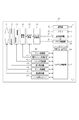
以下、図面を参照して第1の実施形態を説明する。図1は、本実施形態における撮像装置の1例としてのデジタルカメラ10のブロック図である。なお、図1において実線矢印は制御線等の信号線を表わし、波線矢印は通信線を表わす。
(First embodiment)
The first embodiment will be described below with reference to the drawings. FIG. 1 is a block diagram of a
撮影レンズ11は、ズーム制御部44からの制御信号または測距制御部45からの制御信号に従ってレンズ位置を動かす。
The taking
絞り12は、絞り制御部43から出力される絞り制御信号に従って開閉し、入射する光の量を制御する。
The
シャッタ13は、シャッタ制御部42から送られてくるシャッタ制御信号に従って、シャッタを動作させる。
The
撮像素子14は、電子シャッタ制御部41から送られてくる電子シャッタ制御信号に従い、撮影レンズ11、絞り12、シャッタ13の光学系から導かれる光束による光学像(被写体像)を電気信号に変換してAGC(オートゲインコントロール)回路15に出力する。
The
AGC回路15は、ゲイン制御部40から送られてくるゲイン制御信号に従い、撮像素子14から送られてくる画像データのゲイン調整をして、A/D(アナログ/デジタル)変換器16に出力する。
The
A/D変換器16は、AGC回路15から送られてくるゲイン調整された画像データにA/D変換を行う。A/D変換後の画像データは、画像処理部20、メモリ制御部21を介して、或いは画像処理部20を介さずに直接メモリ制御部21から、メモリ30に書き込まれる。
The A /
画像処理部20は、A/D変換器16からのデータ或いはメモリ制御部21からのデータに対して所定の画素補正処理、AWB(オートホワイトバランス)処理、色変換処理、特定色データの抽出等の画像処理を行う。本実施形態では、A/D変換後の画像データはR(赤)/G(緑)/B(青)の信号値がベイヤー配列をなしており、画像処理部20は画素補間処理により画素ごとにR/G/Bの信号値を持つように補間される。その後、AWB処理が行われ、色変換処理にてY(輝度)、UV(色差)信号値に変換されて出力される。しかし、入力される画像データの信号の形態及び画像処理部20から出力される画像データの形態はこれに限らない。
The
また画像処理部20は、撮像した画像データを用いて所定の演算処理を行い、得られた演算結果に基づいてシステム制御部50が各部を制御する。例えば、測距制御部45に対してTTL(スルー・ザ・レンズ)方式のAF(オートフォーカス)処理を実行する。また、ゲイン制御部40、電子シャッタ制御部41、シャッタ制御部42、絞り制御部43、ストロボユニット46に対してAE(自動露出)処理を実行する。さらに、ストロボユニット46に対して、EF(ストロボプリ発光)処理を実行する。また、メモリ30に記憶してある画像データを読みだして、記録部70に送信する。
The
メモリ制御部21は、A/D変換器16、画像処理部20、メモリ30を制御する。
The
ゲイン制御部40は、AGC回路15に、撮像素子14から出力される信号に掛けるゲイン値の指示信号を送信する。
The
電子シャッタ制御部41は、撮像素子14を制御して、撮像素子14に取り込まれる電荷の蓄積開始タイミング及び蓄積量を制御する。
The electronic
シャッタ制御部42は、シャッタ13を制御することでシャッタースピードを制御する。絞り制御部43は絞り12の口径を制御することで、撮像素子14に導く光束を制御する。
The
ズーム制御部44は、撮影レンズ11のレンズ位置を制御することでズーミングを制御する。
The
測距制御部45は、撮影レンズ11のレンズ位置を制御することでフォーカシングを制御する。
The distance
ストロボユニット46は、AF補助光の投光機能、ストロボ調光機能を有する。 The strobe unit 46 has an AF auxiliary light projecting function and a strobe light control function.
ここで、調光機能はプリ発光で被写界の反射光や特定色検知を行い、被写界が適正な露出となるようにストロボの発光量を決定する技術である。 Here, the dimming function is a technique for detecting the amount of light emitted from the strobe so that the reflected light of the object scene or a specific color is detected by pre-emission and the object scene is exposed appropriately.
また、ストロボユニットがバウンス機構を有する場合、バウンス位置に応じてプリ発光の発光量や、特定色検知処理を変更する。 When the strobe unit has a bounce mechanism, the amount of pre-emission light and the specific color detection process are changed according to the bounce position.
システム制御部50は、各部に制御信号を送るなどしてデジタルカメラ10全体の動作を制御している。
The
メモリ30は、このシステム制御部50の動作用の定数、変数、プログラム等を記憶している。また、各部で行われる処理動作における作業用のメモリとしても用いられる。
The
シャッタスイッチ60は、シャッタスイッチSW1とSW2から成り、SW1は、不図示のシャッタボタンの操作途中でオンとなり、AF(オートフォーカス)処理、AE(自動露出)処理等の動作開始を指示する。SW2は、不図示のシャッタボタンの操作完了でオンとなる。ストロボ撮影モードの場合は、SW2のオンによってストロボユニット46の発光制御、及び撮像素子14から読み出した信号をA/D変換器16、メモリ制御部21を介してメモリ30に画像データとして書き込む露光処理の開始を指示する。さらに画像処理部20やメモリ制御部21での演算を用いた現像処理、メモリ30から画像データを読み出し、記録部70に画像データを書き込む記録処理という一連の処理の動作開始を指示する。
The
記録部70は、画像処理部20から送られてくる画像信号を記録媒体に記録する。
The
以下、図2乃至図4のフローチャートと図5の画像データを参照して、本実施形態に係る撮影動作を説明する。 Hereinafter, the shooting operation according to the present embodiment will be described with reference to the flowcharts of FIGS. 2 to 4 and the image data of FIG.
図2は、撮影前の待機状態から撮影開始までの動作を示すフローチャート図である。 FIG. 2 is a flowchart showing the operation from the standby state before shooting to the start of shooting.
ステップS101で、シャッタースイッチ(SW1)が押されていると、ステップS102に進む。 If the shutter switch (SW1) is pressed in step S101, the process proceeds to step S102.
ステップS102では、A/D変換器16から入力された画像データに対して、測距及び測光処理を行う。尚、ステップS102の測距及び測光処理の詳細は図3のフローチャートを参照して詳しく後述する。
In step S102, distance measurement and photometry processing are performed on the image data input from the A /
ステップS103でシャッタスイッチ(SW2)が押されると、ステップS105に進む。 When the shutter switch (SW2) is pressed in step S103, the process proceeds to step S105.
ステップS104でシャッタースイッチ(SW2)が押されずに、更にシャッタースイッチ(SW1)も解除されるとステップS101に戻る。 If the shutter switch (SW2) is not pressed in step S104 and the shutter switch (SW1) is also released, the process returns to step S101.
ステップS105では、ステップS102の測光結果より、ストロボの発光モードを参照して、もしくは平均輝度値を見て平均輝度値が所定値未満であるか否かを判定する。ここで、判定する輝度値は単純な加算平均による平均輝度値に限らず、特定被写体に重みを付けた重みづけ平均、または特定被写体の領域に限定した輝度値などでもよい。 In step S105, it is determined from the photometric result of step S102 whether the average luminance value is less than a predetermined value with reference to the flash emission mode or by looking at the average luminance value. Here, the luminance value to be determined is not limited to an average luminance value obtained by simple addition averaging, but may be a weighted average obtained by weighting a specific subject, a luminance value limited to a specific subject area, or the like.
ステップS150では、ステップS105で平均輝度値が所定値以上と判定された場合、もしくはストロボモードを非発光に設定していた場合に、ストロボを発光させずに通常の撮影を行う。 In step S150, if it is determined in step S105 that the average luminance value is equal to or greater than a predetermined value, or if the flash mode is set to non-flash, normal shooting is performed without causing the flash to fire.
ステップS106では、ステップS102の測光結果より、画像処理部20、又はシステム制御部50で、AE処理を行う。具体的には、画像処理部20で算出した輝度レベルに基づいて絞りの口径、電子シャッタ速度、ゲインなどの制御値を算出する。システム制御部50は、算出された制御値に応じた制御値をゲイン制御部40、電子シャッタ制御部41、絞り制御部43に送信する。
In step S106, AE processing is performed by the
また、画像処理部20で算出された輝度レベル、測距結果に基づくレンズ駆動量から、ストロボユニット46をプリ発光した時に、特定色などの反射光輝度レベルが適正なレベルで得ることができる絞りの口径、電子シャッタ速度、ゲインなどの制御値などを設定する。
Further, when the strobe unit 46 is pre-flashed based on the brightness level calculated by the
尚、絞りの口径、ストロボのプリ発光光量は、被写体が階調不良にならない程度に設定し、また、外光の影響を極力少なくするために電子シャッタの速度は高速度に設定し、画像信号のノイズを低減するために低めのゲインを設定する。 Note that the aperture diameter and the pre-flash light intensity of the strobe are set to such an extent that the subject does not have poor gradation, and the electronic shutter speed is set to a high speed in order to reduce the influence of external light as much as possible. Set a lower gain to reduce noise.
ステップS107では、絞り12、撮像素子14、AGC回路15に口径、電子シャッタ速度、ゲインなどの制御値が設定されると、ストロボユニット46を発光させずに被写体の撮影を行う。画像信号は撮像素子部14、AGC回路15、A/D変換器16を介して画像処理部20に送信され、ここで所定の処理を施された後、非発光画像としてメモリ30に記憶する。
In step S107, when control values such as the aperture, the electronic shutter speed, and the gain are set in the
ステップS108では、ストロボユニット46を発光(プリ発光)させて撮影を行い、撮像素子部14、AGC回路15、A/D変換器16を介して画像処理部20に送信され、ここで所定の処理を施された後、プリ発光画像としてメモリ30に記憶する。
In step S108, the strobe unit 46 emits light (pre-emission) to perform photographing, and is transmitted to the
ステップS109では、画像処理部20にて、メモリ30に記憶されている非発光画像データとプリ発光画像データを読み出し、2つの画像データを画素単位で差分をとり、反射光輝度データを生成する。
In step S109, the
ここで、非発光画像データの光源である環境光と、プリ発光画像データの光源である環境光とストロボ光の差分をとることで、環境光の影響を除去した画像データを取得することができ、光源をストロボ光のみとした反射光輝度データを生成できる。 Here, by taking the difference between the ambient light, which is the light source of the non-emission image data, and the ambient light, which is the light source of the pre-emission image data, and the strobe light, it is possible to obtain image data from which the influence of the ambient light has been removed. The reflected light luminance data with only the strobe light as the light source can be generated.
ステップS110では、ストロボユニット46との通信により、ストロボユニット46がバウンス撮影であるか否かを判別する。 In step S110, it is determined whether or not the flash unit 46 is bounce shooting through communication with the flash unit 46.
ステップS111では、ストロボのプリ発光画像撮影時の色温度情報を取得する。内蔵のストロボを使用する場合には、予め画像処理部20又はメモリ30などに記憶した色温度情報を読み出す。
In step S111, color temperature information at the time of shooting the pre-flash image of the strobe is acquired. When the built-in strobe is used, the color temperature information stored in advance in the
ステップS112では、ホワイトバランス制御を行う。ステップS111で得られたストロボユニット46の色温度情報をメモリから読み出し、ストロボユニット46の色温度(分光特性)に応じて画像データのR/G/Bの各信号値のゲインを調整する。即ち、光源をストロボのみに限定することができるため、より正確なホワイトバランス補正を行うことが可能となる。 In step S112, white balance control is performed. The color temperature information of the strobe unit 46 obtained in step S111 is read from the memory, and the gain of each R / G / B signal value of the image data is adjusted according to the color temperature (spectral characteristic) of the strobe unit 46. That is, since the light source can be limited to only the strobe, more accurate white balance correction can be performed.
ステップS160では、ストロボユニット46がバウンス状態の場合には、光源をストロボ光に限定することができないため、既知のオートホワイトバランス処理を行い、R/G/B各色のゲインを調整する。 In step S160, when the strobe unit 46 is in the bounce state, the light source cannot be limited to strobe light, so known auto white balance processing is performed to adjust the gain of each R / G / B color.
ステップS113では、ゲイン調整画像データに基づいて所定の演算を行い、発光量の目標値を算出する。算出した発光量の目標値に基づいたストロボ制御信号をストロボユニット46に設定する。尚、本演算は図4のフローチャートを参照して詳しく後述する。 In step S113, a predetermined calculation is performed based on the gain adjustment image data to calculate a target value of the light emission amount. A strobe control signal based on the calculated target amount of light emission is set in the strobe unit 46. This calculation will be described later in detail with reference to the flowchart of FIG.
ステップS114では、ストロボユニット46に設定した本発光量に基づいてストロボを発光させて、被写体の本撮影が行われる。 In step S114, the strobe is fired based on the main light emission amount set in the strobe unit 46, and the subject is actually photographed.
図3は、図2のステップS102における測距及び測光処理の詳細を示すフローチャートである。 FIG. 3 is a flowchart showing details of distance measurement and photometry processing in step S102 of FIG.
まずステップS201で、撮像素子14から電荷信号を読み出し、A/D変換器16を介してデジタルデータに変換し、そのデジタルデータを画像処理部20に入力する。
First, in step S <b> 201, a charge signal is read from the
ステップS202では、画像処理部20にて、入力された画像データから光源の色温度を判断し、各画素の色毎に所定のゲインをかける(AWB処理)。
In step S202, the
ステップS203では、画像処理部20にて、入力された画像データを用いて既知のコントラスト方式のAF(オートフォーカス)処理を行う。
In step S203, the
ステップS204では、上述の画像データに対して所定の処理を行い、露光量の目標値を算出する。算出した露光量の目標値に基づいて絞り、シャッタ速度、ゲインの調整値を決定する。尚、本演算は図4のフローチャートを参照して詳しく後述する。 In step S204, a predetermined process is performed on the above-described image data to calculate a target value for the exposure amount. Based on the calculated exposure target value, the aperture, shutter speed, and gain adjustment values are determined. This calculation will be described later in detail with reference to the flowchart of FIG.
図4は、図2のステップS113及び図3のステップS204における輝度演算の詳細を示すフローチャートである。 FIG. 4 is a flowchart showing details of the luminance calculation in step S113 of FIG. 2 and step S204 of FIG.
図5は、図4の各ステップをイメージ図で説明したものである。 FIG. 5 illustrates each step of FIG. 4 with an image diagram.
ステップS301では、図2のステップS112と、図3のステップS203から画像データが入力され、画像処理部20にて所定面積の測定ブロックに分割する。
In step S301, image data is input from step S112 in FIG. 2 and step S203 in FIG. 3, and the
図5(a)は、人物が撮像素子14のリニアリティ範囲内(ダイナミックレンジ内)で撮影出来ており、その背景がダイナミックレンジ外の範囲の信号値で白つぶれしてしまっている画像データの例を示している。
FIG. 5A shows an example of image data in which a person can be photographed within the linearity range (within the dynamic range) of the
図5(b)は、画像データ(a)を4×4の測定ブロック200に分割したものである。 FIG. 5B shows the image data (a) divided into 4 × 4 measurement blocks 200.
ステップS302では、測定ブロック内の複数の色成分を含む複数画素ずつの画素グループに分け、該画素グループ内の画素出力全てが撮像素子14のリニアリティ範囲に入るグループ数(割合)を算出する。
In step S302, the pixel group is divided into a plurality of pixels each including a plurality of color components in the measurement block, and the number (ratio) of groups in which all pixel outputs in the pixel group fall within the linearity range of the
図5(c)は、(3,3)ブロックを40個のグループに細分化した例である。該グループ内の複数の色成分の画素出力全てが撮像素子14のリニアリティ範囲(ダイナミックレンジ)に対応する所定の範囲内に入るグループを所定範囲内グループ210とする。図5(d)は、ブロック毎に所定範囲内グループ数を算出したものである。(0,0)ブロックに示したように、背景が白つぶれしている場合には、所定範囲内グループ数は0となる。
FIG. 5C shows an example in which the (3, 3 ) block is subdivided into 40 groups. A group in which all pixel outputs of a plurality of color components in the group fall within a predetermined range corresponding to the linearity range (dynamic range) of the
ステップS303では、該所定範囲内グループ数が所定数以上存在するか否かを判別する。 In step S303, it is determined whether or not there are a predetermined number or more groups within the predetermined range.
図5(d)では、所定数を20とした時に、所定数以上存在すると判定されたブロックを所定範囲内ブロック220として表示している。
In FIG. 5D, when the predetermined number is set to 20, the blocks determined to be present at a predetermined number or more are displayed as the
ステップS304では、ステップS301で分割したブロック単位で、ブロック内の画素全体の輝度の平均値である全体輝度平均値を算出する。 In step S304, the overall luminance average value, which is the average value of the luminance of all the pixels in the block, is calculated for each block divided in step S301.
図5(e)は、ブロック毎に輝度平均値を算出したものである。 FIG. 5E shows an average luminance value calculated for each block.
ステップS305では、ブロック毎に、該画素グループ内の画素出力がそれぞれ所定の範囲内に入る画素グループのみを使用した輝度平均値と色成分毎の平均値を算出する。 In step S305, for each block, an average luminance value and an average value for each color component are calculated using only pixel groups in which the pixel outputs in the pixel group fall within a predetermined range.
図5(f)、(g)は、所定範囲内ブロック220内の所定の範囲内に入る画素グループのみを使用した輝度平均値と色成分毎の色成分平均値である。
FIGS. 5F and 5G show the luminance average value and the color component average value for each color component using only the pixel group that falls within the predetermined range in the
ステップS306では、ステップS305で求めた該所定範囲内の色成分毎の平均値が、特定色を示す色空間上の所定領域の中に存在するか否かを判定し、存在するブロックを特定色ブロックと判定する。 In step S306, it is determined whether or not the average value for each color component within the predetermined range obtained in step S305 exists in a predetermined area on the color space indicating the specific color, and the existing block is determined as the specific color. Judge as a block.
ステップS307では、特定色ブロックの判定結果や所定範囲内グループの数に応じて、ブロックごとの重み付け係数を調節する。重み付け係数の調節は図7を参照して詳しく後述する。 In step S307, the weighting coefficient for each block is adjusted according to the determination result of the specific color block and the number of groups in the predetermined range. The adjustment of the weighting coefficient will be described later in detail with reference to FIG.
図5(h)は、特定色として肌色を抽出したときの結果を特定色ブロック230として示し、特定色に応じた重み付け係数を示したものである。
FIG. 5H shows the result when the skin color is extracted as the specific color as a
ステップS308では、ステップS307より算出された重み付け係数と、ステップS304、もしくはステップS306より検出したブロック毎の輝度平均値との加重平均により、特定色を最適な露出で撮影するための露光量、本発光量の目標値を算出する。
In step S308, the weighting coefficient calculated from the
図5(i)は、ステップS304、もしくはステップS306より検出したブロック毎の輝度平均値である。所定範囲内ブロック220は図5(f)に示す所定範囲内輝度平均値、所定範囲内ブロック以外のブロックは図5(e)に示す輝度平均値を輝度平均値とする。
FIG. 5I shows the average luminance value for each block detected in step S304 or step S306. The
図5(j)は、図5(i)に示した輝度平均値と図5(h)に示した重み付け係数の乗算値の総和“5650”から、重み付け係数の総和“285”で除算処理(加重平均処理)によって、目標値“19.8”を算出する。 FIG. 5J illustrates a division process (from the sum “5650” of the multiplication value of the luminance average value illustrated in FIG. 5I and the weighting coefficient illustrated in FIG. 5H by the sum “285” of the weighting coefficient ( The target value “19.8” is calculated by weighted average processing.
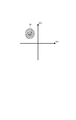
次に、上述した図2及び図3のフローチャートにおいて、特定色の被写体を抽出するときの抽出方法について、図6を用いて具体的に説明する。 Next, an extraction method for extracting a subject of a specific color in the flowcharts of FIGS. 2 and 3 described above will be specifically described with reference to FIG.
図6は、縦軸R/G、横軸B/Gの色差平面を簡略化したグラフである。 FIG. 6 is a graph in which the color difference plane of the vertical axis R / G and the horizontal axis B / G is simplified.
特定色の抽出では、まず撮影環境における光源の色温度を判定してオートホワイトバランス制御を行う。これは、画面内の画像から得られる輝度情報や色情報により光源の色温度を推定し、白い被写体を撮影した時に、各R、G、Bの画素出力が同一のレベルになるように、R、G、Bのゲインを調整する既知の技術である。 In extracting a specific color, first, the color temperature of the light source in the shooting environment is determined to perform auto white balance control. This is because the color temperature of the light source is estimated from the luminance information and color information obtained from the image in the screen, and when a white subject is photographed, the R, G, B pixel outputs are at the same level. , G, and B are known techniques for adjusting gains.
尚、ストロボ使用時にストロボがバウンス撮影ではない場合には、プリ発光の色温度がわかっているので、これを光源の色温度とする。 If the strobe is not bounce shooting when the strobe is used, the color temperature of the pre-light emission is known, and this is used as the color temperature of the light source.
ストロボユニット46がバウンス撮影時には、ストロボが周辺の反射物を介して被写体にストロボ光が届くため、反射物の反射率によって色温度(分光特性)が変化する。 When the strobe unit 46 performs bounce shooting, the strobe light reaches the subject through the surrounding reflectors, so that the color temperature (spectral characteristics) changes depending on the reflectance of the reflectors.
そのため、バウンス撮影時には、画像データの色情報などにより、既知の手段でホワイトバランスの制御を行う。 Therefore, at the time of bounce shooting, white balance is controlled by a known means based on color information of image data.
ホワイトバランス制御した画像データより、ブロックの色成分毎の平均値をB/G値とR/G値の色差信号とする。色差信号の二次元平面上(色空間)において、特定色がプロットされる範囲が決まっているため、ブロック毎のダイナミックレンジ内色成分毎の平均値が色空間上で特定色を示す所定範囲内に入るか否かを判定する(ステップS306)。 From the image data subjected to white balance control, an average value for each color component of the block is used as a color difference signal of B / G value and R / G value. Since the range in which the specific color is plotted is determined on the two-dimensional plane (color space) of the color difference signal, the average value for each color component within the dynamic range for each block is within the predetermined range indicating the specific color on the color space. It is determined whether or not to enter (step S306).
例えば、特定色として肌色を抽出する場合に、肌色は図6に示す色空間において左上(第二象限)の範囲に存在することがわかっているため、左上の範囲に特定色枠を設定し、肌色の抽出を行う。 For example, when extracting the skin color as the specific color, since it is known that the skin color exists in the upper left (second quadrant) range in the color space shown in FIG. 6, a specific color frame is set in the upper left range, Performs skin color extraction.
ここで、グループ内のR、G、B画素1色でも撮像素子14のリニアリティ範囲外であると、R、G、Bの比率が変化し色空間上で異なる位置にプロットされてしまう。
Here, if even one color of R, G, and B pixels in the group is outside the linearity range of the
そのため、ブロック内で複数の色成分を含む数画素ずつの画素グループ内の画素出力全てが所定の範囲内に入る画素のみを使用した色成分毎の平均値が色空間上で特定色枠に入るか否かの判定を行う。 For this reason, an average value for each color component using only pixels in which all pixel outputs in a pixel group of several pixels including a plurality of color components in a block fall within a predetermined range enters a specific color frame on the color space. It is determined whether or not.
該ブロック内でリニアリティ範囲内のグループ数が所定のグループ数より少ない(所定のグループ割合より小さい)場合には、ブロック内の特定色の割合がそもそも小さいため、該ブロックが特定色枠に入るか否かの判定は行わない。 If the number of groups in the linearity range in the block is smaller than the predetermined number of groups (smaller than the predetermined group ratio), the specific color ratio in the block is small in the first place. No determination is made.
また、外付けストロボを使用する場合には、ストロボユニット46との通信により、ストロボユニット46のプリ発光時の色温度を取得する。内蔵のストロボを使用する場合には、予め画像処理部又はメモリなどに記憶したデータを読み出す。 When an external strobe is used, the color temperature at the time of pre-flash of the strobe unit 46 is acquired through communication with the strobe unit 46. When using a built-in flash, data stored in advance in an image processing unit or memory is read.
次に、ストロボを発光せずに被写体を撮影した非発光画像データを取得し、メモリ30に記憶する。次に、ストロボユニット46を発光させて被写体を撮影したプリ発光画像データをメモリ30に記憶し、記憶した2つの画像データを画素単位で差分をとり、反射光輝度データを生成する。
Next, non-light-emitting image data obtained by photographing the subject without flashing is acquired and stored in the
ここで、非発光画像データの光源である環境光と、プリ発光画像データの光源である環境光とストロボ光の差分演算をとることで、環境光の影響を除去した反射光画像データを取得することができ、光源をストロボ光に特定することができる。 Here, the reflected light image data from which the influence of the ambient light is removed is obtained by calculating the difference between the ambient light that is the light source of the non-emission image data and the ambient light that is the light source of the pre-emission image data and the strobe light. The light source can be specified as strobe light.
ストロボユニット46のプリ発光時の分光特性は、ストロボユニットとの通信により取得するか、予め画像処理部20又はメモリ30などに記憶したデータを読み出すことで取得する。
The spectral characteristics of the strobe unit 46 during pre-emission are acquired by communication with the strobe unit or by reading data stored in advance in the
ストロボユニット46の分光特性と撮像素子14の分光特性は常に一定の値となるため、ストロボと撮像素子の分光特性データを予め画像処理部20又はメモリ30などに記憶しておく。画像処理部20は色温度データや分光特性データを分析し、分析結果に基づいて反射光画像データのR、G、Bのゲイン(ホワイトバランス調整値)を調整することで、正確なホワイトバランス調整が可能となる。
Since the spectral characteristic of the strobe unit 46 and the spectral characteristic of the
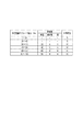
次に、上述した図2及び図3のフローチャートにおいて、重み付け係数の調節方法について、図7を用いて具体的に説明する。 Next, in the flowcharts of FIGS. 2 and 3 described above, a method of adjusting the weighting coefficient will be specifically described with reference to FIG.
図7は、各特定色、非特定色への重み付け係数を表にまとめたものである。該所定範囲内グループ数に応じて、重み付け係数値を調節する。 FIG. 7 is a table summarizing the weighting coefficients for each specific color and non-specific color. The weighting coefficient value is adjusted according to the number of groups within the predetermined range.
例えば、特定色として肌色を抽出した場合には、その領域を適正な露出で撮影するために、大きい重み付け係数値を設定する。 For example, when a skin color is extracted as the specific color, a large weighting coefficient value is set in order to capture the area with appropriate exposure.
ストロボ発光時に、特定色として反射率の高い鏡や金屏風を検出した場合には、その反射光の影響を抑制するため、他のブロックに比べて重み付け係数値を小さく設定する。 When a high-reflectivity mirror or gold screen is detected as a specific color during strobe light emission, the weighting coefficient value is set to be smaller than other blocks in order to suppress the influence of the reflected light.
また、非特定色のブロックも、該所定範囲内グループ数が小さい場合には、重み付け係数を小さく設定する。これは、画面内でダイナミックレンジ外の物体が及ぼす影響を抑制するためである。 Also, the non-specific color block is set to have a small weighting coefficient when the number of groups in the predetermined range is small. This is to suppress the influence of objects outside the dynamic range in the screen.
以上のように、本実施形態では、発光画像と非発光画像との差分から特定色を検出する処理において、各ブロックでダイナミックレンジ内の色成分毎の平均値が色空間上で特定色を示す所定範囲内に入る画素グループを検出する。該画素グループの各ブロックに占める割合に基づいて各ブロックの重みづけ係数を決めて最終的な露出制御を行う。これらの処理により、ダイナミックレンジ外の物体が及ぼす影響を抑制し、人間の肌色を適正な露出で撮影することができる。また、反射率の高い鏡や金屏風の反射光の影響を抑える適正な露出で撮影することができる。 As described above, in the present embodiment, in the process of detecting a specific color from the difference between the light emission image and the non-light emission image, the average value for each color component within the dynamic range in each block indicates the specific color in the color space. A pixel group falling within a predetermined range is detected. The final exposure control is performed by determining the weighting coefficient of each block based on the ratio of the pixel group to each block. By these processes, the influence of an object outside the dynamic range can be suppressed, and human skin color can be photographed with appropriate exposure. In addition, it is possible to take a picture with an appropriate exposure that suppresses the influence of a mirror having a high reflectivity or reflected light from a gold screen.
以上、本発明の好ましい実施形態について説明したが、本発明はこれらの実施形態に限定されず、その要旨の範囲内で種々の変形及び変更が可能である。 As mentioned above, although preferable embodiment of this invention was described, this invention is not limited to these embodiment, A various deformation | transformation and change are possible within the range of the summary.
(他の実施形態)
本発明の目的は以下のようにしても達成できる。すなわち、前述した各実施形態の機能を実現するための手順が記述されたソフトウェアのプログラムコードを記録した記憶媒体を、システムまたは装置に供給する。そしてそのシステムまたは装置のコンピュータ(またはCPU、MPU等)が記憶媒体に格納されたプログラムコードを読み出して実行するのである。
(Other embodiments)
The object of the present invention can also be achieved as follows. That is, a storage medium in which a program code of software in which a procedure for realizing the functions of the above-described embodiments is described is recorded is supplied to the system or apparatus. The computer (or CPU, MPU, etc.) of the system or apparatus reads out and executes the program code stored in the storage medium.
この場合、記憶媒体から読み出されたプログラムコード自体が本発明の新規な機能を実現することになり、そのプログラムコードを記憶した記憶媒体およびプログラムは本発明を構成することになる。 In this case, the program code itself read from the storage medium realizes the novel function of the present invention, and the storage medium and program storing the program code constitute the present invention.
また、プログラムコードを供給するための記憶媒体としては、例えば、フレキシブルディスク、ハードディスク、光ディスク、光磁気ディスクなどが挙げられる。また、CD−ROM、CD−R、CD−RW、DVD−ROM、DVD−RAM、DVD−RW、DVD−R、磁気テープ、不揮発性のメモリカード、ROM等も用いることができる。 Examples of the storage medium for supplying the program code include a flexible disk, a hard disk, an optical disk, and a magneto-optical disk. Further, a CD-ROM, CD-R, CD-RW, DVD-ROM, DVD-RAM, DVD-RW, DVD-R, magnetic tape, nonvolatile memory card, ROM, or the like can also be used.
また、コンピュータが読み出したプログラムコードを実行可能とすることにより、前述した各実施形態の機能が実現される。さらに、そのプログラムコードの指示に基づき、コンピュータ上で稼動しているOS(オペレーティングシステム)等が実際の処理の一部または全部を行い、その処理によって前述した各実施形態の機能が実現される場合も含まれる。 Further, by making the program code read by the computer executable, the functions of the above-described embodiments are realized. Furthermore, when the OS (operating system) running on the computer performs part or all of the actual processing based on the instruction of the program code, the functions of the above-described embodiments are realized by the processing. Is also included.
更に、以下の場合も含まれる。まず記憶媒体から読み出されたプログラムコードが、コンピュータに挿入された機能拡張ボードやコンピュータに接続された機能拡張ユニットに備わるメモリに書き込まれる。その後、そのプログラムコードの指示に基づき、その機能拡張ボードや機能拡張ユニットに備わるCPU等が実際の処理の一部または全部を行う。 Furthermore, the following cases are also included. First, the program code read from the storage medium is written in a memory provided in a function expansion board inserted into the computer or a function expansion unit connected to the computer. Thereafter, based on the instruction of the program code, the CPU or the like provided in the function expansion board or function expansion unit performs part or all of the actual processing.
10 撮像装置
11 撮影レンズ
12 絞り
13 シャッタ
14 撮像素子
15 AGC回路
16 A/D変換器
20 画像処理部
21 メモリ制御部
30 メモリ
40 ゲイン制御部
41 電子シャッタ制御部
42 シャッタ制御部
43 絞り制御部
44 ズーム制御部
45 測距制御部
46 ストロボユニット
50 システム制御部
60 記録部
DESCRIPTION OF
Claims (13)
前記撮像手段で撮像を行い得られた画像データに基づいて複数の測光ブロックごとに代表輝度値を算出する輝度値算出手段と、
前記複数の測光ブロックのそれぞれについて、前記測光ブロックに含まれる複数の小ブロックのうち出力値が所定の範囲内となる小ブロックが所定値以上存在するか否かを判定する判定手段と、
前記輝度値算出手段により算出された複数の前記代表輝度値に基づいて露光量を算出する露光量算出手段と、
前記複数の測光ブロックごとに重み付け係数を決定する決定手段と、を有し、
前記輝度値算出手段は、前記判定手段により出力値が所定の範囲内となる小ブロックが所定値以上存在すると判定された測光ブロックについては、出力値が前記所定の範囲内とならない小ブロックを除いた小ブロックの出力値に基づいて前記代表輝度値を算出し、
前記決定手段は、前記判定手段により出力値が前記所定の範囲内となる小ブロックが前記所定値以上存在すると判定された測光ブロックについては、出力値が前記所定の範囲内となる小ブロックの色情報と出力値が前記所定の範囲内となる小ブロックの数または割合に応じた重み付け係数を決定し、
前記露光量算出手段は、前記輝度値算出手段により算出された複数の前記代表輝度値と前記決定手段により決定された重み付け係数とに基づいて露光量を算出することを特徴とする撮像装置。 And an imaging means,
Luminance value calculating means for calculating a representative luminance value for each of a plurality of photometric blocks based on image data obtained by imaging with the imaging means;
For each of the plurality of photometric blocks, a determination unit that determines whether or not a small block whose output value is within a predetermined range among a plurality of small blocks included in the photometric block is greater than or equal to a predetermined value;
An exposure amount calculating means for calculating an exposure amount based on the plurality of representative brightness values calculated by the brightness value calculating means;
Determining means for determining a weighting coefficient for each of the plurality of photometric blocks ;
The luminance value calculating means excludes small blocks whose output values are not within the predetermined range for the photometric blocks for which the determination means determines that there are more than a predetermined value of small blocks whose output values are within the predetermined range. The representative luminance value is calculated based on the output value of the small block ,
The determining means determines the color of the small block whose output value is within the predetermined range for the photometric block for which it is determined that the small block whose output value is within the predetermined range exists by the determining means. Determine a weighting factor according to the number or proportion of small blocks whose information and output value fall within the predetermined range;
The imaging apparatus according to claim 1, wherein the exposure amount calculation unit calculates an exposure amount based on the plurality of representative luminance values calculated by the luminance value calculation unit and the weighting coefficient determined by the determination unit.
前記複数の測光ブロックのそれぞれについて、前記測光ブロックに含まれる複数の小ブロックのうち出力値が所定の範囲内となる小ブロックが所定値以上存在するか否かを判定する判定ステップと、
前記輝度値算出ステップにより算出された複数の前記代表輝度値に基づいて露光量を算出する露光量算出ステップと、
前記複数の測光ブロックごとに重み付け係数を決定する決定ステップと、を有し、
前記輝度値算出ステップは、前記判定ステップで出力値が所定の範囲内となる小ブロックが所定値以上存在すると判定された測光ブロックについては、出力値が前記所定の範囲内とならない小ブロックを除いた小ブロックの出力値に基づいて前記代表輝度値を算出し、
前記決定ステップは、前記判定ステップで出力値が前記所定の範囲内となる小ブロックが前記所定値以上存在すると判定された測光ブロックについては、出力値が前記所定の範囲内となる小ブロックの色情報と出力値が前記所定の範囲内となる小ブロックの数または割合に応じた重み付け係数を決定し、
前記露光量算出ステップは、前記輝度値算出ステップで算出された複数の前記代表輝度値と前記決定ステップで決定された重み付け係数とに基づいて露光量を算出することを特徴とする撮像装置の制御方法。 A luminance value calculation death step of calculating a representative luminance value for each of the plurality of light metering blocks on the basis of image data obtained captures an image by the imaging means,
For each of the plurality of photometric blocks, a determination step of determining whether or not a small block whose output value is within a predetermined range among a plurality of small blocks included in the photometric block is greater than or equal to a predetermined value;
An exposure amount calculating step of calculating an exposure amount based on the plurality of representative luminance values calculated by the luminance value calculating step;
Determining a weighting factor for each of the plurality of photometric blocks ,
The luminance value calculating step, the decision for the photometric block small block is determined to exist more than a predetermined value the output value falls within a predetermined range in the step, the small block output value is not et such as within the predetermined range calculating the representative luminance value on the basis of the output values of the small blocks, excluding,
In the determination step, for a photometric block in which it is determined in the determination step that a small block whose output value falls within the predetermined range is greater than the predetermined value, the color of the small block whose output value falls within the predetermined range Determine a weighting factor according to the number or proportion of small blocks whose information and output value fall within the predetermined range;
The exposure amount calculating step calculates an exposure amount based on the plurality of representative luminance values calculated in the luminance value calculating step and the weighting coefficient determined in the determining step. Method.
Priority Applications (4)
| Application Number | Priority Date | Filing Date | Title |
|---|---|---|---|
| JP2011155908A JP5885416B2 (en) | 2011-07-14 | 2011-07-14 | IMAGING DEVICE AND IMAGING DEVICE CONTROL METHOD |
| US13/545,767 US9131197B2 (en) | 2011-07-14 | 2012-07-10 | Imaging apparatus capable of controlling exposure including flash amount control of flash apparatus, and control method thereof |
| EP12175940.1A EP2547092A3 (en) | 2011-07-14 | 2012-07-11 | Imaging apparatus capable of controlling exposure including flash amount control of flash apparatus, and control method thereof |
| CN201210244126.4A CN102883107B (en) | 2011-07-14 | 2012-07-13 | Picture pick-up device and control method thereof |
Applications Claiming Priority (1)
| Application Number | Priority Date | Filing Date | Title |
|---|---|---|---|
| JP2011155908A JP5885416B2 (en) | 2011-07-14 | 2011-07-14 | IMAGING DEVICE AND IMAGING DEVICE CONTROL METHOD |
Publications (3)
| Publication Number | Publication Date |
|---|---|
| JP2013021658A JP2013021658A (en) | 2013-01-31 |
| JP2013021658A5 JP2013021658A5 (en) | 2015-02-19 |
| JP5885416B2 true JP5885416B2 (en) | 2016-03-15 |
Family
ID=46679095
Family Applications (1)
| Application Number | Title | Priority Date | Filing Date |
|---|---|---|---|
| JP2011155908A Expired - Fee Related JP5885416B2 (en) | 2011-07-14 | 2011-07-14 | IMAGING DEVICE AND IMAGING DEVICE CONTROL METHOD |
Country Status (4)
| Country | Link |
|---|---|
| US (1) | US9131197B2 (en) |
| EP (1) | EP2547092A3 (en) |
| JP (1) | JP5885416B2 (en) |
| CN (1) | CN102883107B (en) |
Families Citing this family (21)
| Publication number | Priority date | Publication date | Assignee | Title |
|---|---|---|---|---|
| US8717454B2 (en) * | 2009-12-24 | 2014-05-06 | Samsung Electronics Co., Ltd. | Image pickup apparatus and image pickup method for adjusting white balance to account for flash and external light sources |
| US20130176457A1 (en) * | 2012-01-09 | 2013-07-11 | Sawada Yasuhiro | Auto processing images having arbitrary regions of interest |
| US9411212B2 (en) * | 2013-01-25 | 2016-08-09 | Canon Kabushiki Kaisha | Illumination apparatus which is arrangeable so as to surround an image capturing lens |
| JP6351214B2 (en) * | 2013-06-19 | 2018-07-04 | キヤノン株式会社 | Imaging device, control method thereof, and control program |
| JP5947263B2 (en) * | 2013-08-27 | 2016-07-06 | Necプラットフォームズ株式会社 | Antenna and wireless communication device |
| JP6255931B2 (en) * | 2013-11-19 | 2018-01-10 | リコーイメージング株式会社 | Illumination device, imaging device, illumination method, and reflection region determination device |
| US10154202B2 (en) * | 2014-10-15 | 2018-12-11 | Samsung Electronics Co., Ltd. | Apparatus for illuminating a scene and control method thereof |
| CN104967776B (en) * | 2015-06-11 | 2018-03-27 | 广东欧珀移动通信有限公司 | One kind is taken pictures method to set up and user terminal |
| US10032252B2 (en) * | 2015-10-30 | 2018-07-24 | Canon Kabushiki Kaisha | Image processing apparatus, image capturing apparatus, image processing method, and non-transitory computer readable storage medium |
| TWI588587B (en) * | 2016-03-21 | 2017-06-21 | 鈺立微電子股份有限公司 | Image capture device and operation method thereof |
| JP6727920B2 (en) * | 2016-05-17 | 2020-07-22 | キヤノン株式会社 | Imaging device and control method |
| CN106791472B (en) * | 2016-12-29 | 2019-07-30 | 努比亚技术有限公司 | A kind of exposure method and terminal |
| CN106952244B (en) * | 2017-03-28 | 2020-05-05 | 中航视嘉(北京)技术有限公司 | Automatic image brightness adjusting method and device |
| JP6910837B2 (en) * | 2017-04-14 | 2021-07-28 | キヤノン株式会社 | Image pickup device, image sensor and its control method and program |
| US10154256B1 (en) * | 2017-06-13 | 2018-12-11 | Qualcomm Incorporated | Flash color calibration |
| CN107302663B (en) * | 2017-07-31 | 2020-07-14 | 珠海大横琴科技发展有限公司 | Image brightness adjusting method, terminal and computer readable storage medium |
| CN108810509B (en) * | 2018-07-06 | 2020-08-11 | 北京中安未来科技有限公司 | Image color correction method and device |
| CN111372007B (en) * | 2020-03-03 | 2021-11-12 | 荣耀终端有限公司 | Ambient light illumination detection method and device and electronic equipment |
| CN112702551A (en) * | 2020-12-21 | 2021-04-23 | 上海眼控科技股份有限公司 | Lightning field video recording method, device, equipment and medium |
| CN113099191B (en) * | 2021-03-22 | 2023-04-07 | 浙江大华技术股份有限公司 | Image processing method and device |
| KR20220152019A (en) * | 2021-05-07 | 2022-11-15 | 에스케이하이닉스 주식회사 | Image sensing device and operating method thereof |
Family Cites Families (11)
| Publication number | Priority date | Publication date | Assignee | Title |
|---|---|---|---|---|
| JP3343921B2 (en) | 1991-08-06 | 2002-11-11 | ミノルタ株式会社 | Person adaptive exposure control device |
| JPH11275454A (en) * | 1998-03-23 | 1999-10-08 | Ricoh Co Ltd | Digital video camera |
| JP4277406B2 (en) * | 2000-01-26 | 2009-06-10 | 株式会社ニコン | Image recording device |
| JP4636739B2 (en) | 2001-06-29 | 2011-02-23 | キヤノン株式会社 | IMAGING DEVICE, IMAGING DEVICE CONTROL METHOD, PROGRAM, AND COMPUTER-READABLE STORAGE MEDIUM |
| JP4300936B2 (en) | 2003-08-20 | 2009-07-22 | ソニー株式会社 | Imaging device |
| EP1668918B1 (en) | 2003-08-26 | 2017-06-07 | Casio Computer Co., Ltd. | Image pickup apparatus and white balance control method |
| JP4118864B2 (en) | 2004-11-05 | 2008-07-16 | 三菱電機株式会社 | Imaging device |
| JP4115467B2 (en) | 2005-06-01 | 2008-07-09 | 富士フイルム株式会社 | Imaging device |
| US8107762B2 (en) * | 2006-03-17 | 2012-01-31 | Qualcomm Incorporated | Systems, methods, and apparatus for exposure control |
| JP5169318B2 (en) | 2007-09-18 | 2013-03-27 | 株式会社リコー | Imaging apparatus and imaging method |
| JP2010268134A (en) * | 2009-05-13 | 2010-11-25 | Nikon Corp | Imaging device |
-
2011
- 2011-07-14 JP JP2011155908A patent/JP5885416B2/en not_active Expired - Fee Related
-
2012
- 2012-07-10 US US13/545,767 patent/US9131197B2/en not_active Expired - Fee Related
- 2012-07-11 EP EP12175940.1A patent/EP2547092A3/en not_active Withdrawn
- 2012-07-13 CN CN201210244126.4A patent/CN102883107B/en not_active Expired - Fee Related
Also Published As
| Publication number | Publication date |
|---|---|
| EP2547092A3 (en) | 2016-12-21 |
| US20130016249A1 (en) | 2013-01-17 |
| CN102883107B (en) | 2016-01-06 |
| CN102883107A (en) | 2013-01-16 |
| EP2547092A2 (en) | 2013-01-16 |
| US9131197B2 (en) | 2015-09-08 |
| JP2013021658A (en) | 2013-01-31 |
Similar Documents
| Publication | Publication Date | Title |
|---|---|---|
| JP5885416B2 (en) | IMAGING DEVICE AND IMAGING DEVICE CONTROL METHOD | |
| US8493485B2 (en) | Image pickup device, image pickup apparatus, control method, and program | |
| JP5597243B2 (en) | Imaging device | |
| JP5489591B2 (en) | Imaging apparatus and control method thereof | |
| JP6303304B2 (en) | camera | |
| JP5092565B2 (en) | Imaging apparatus, image processing apparatus, and program | |
| US9888184B2 (en) | Light emission control device, control method therefor, storage medium storing control program therefor, and image pickup apparatus with light emission control device | |
| US10063795B2 (en) | Image capturing apparatus, method for controlling the same, and storage medium | |
| US8559809B2 (en) | Image shooting device | |
| JP5228318B2 (en) | Camera and flash output calculation program | |
| JP2002207159A (en) | Digital camera | |
| JP2008236032A (en) | Photographing device | |
| JP5791765B2 (en) | Imaging apparatus and control method thereof | |
| JP2005065186A (en) | Image pickup unit | |
| JP2012163679A (en) | Imaging device, stroboscope control method, and stroboscope control program | |
| US10873707B2 (en) | Image pickup apparatus and method, for ensuring correct color temperature based on first or second preliminary light emission of a flash device | |
| JP6272006B2 (en) | Imaging apparatus, image processing method, and program | |
| JP2005121834A (en) | Imaging method, imaging apparatus, program, and storage medium | |
| JP5625711B2 (en) | Imaging apparatus and imaging method | |
| JP5791454B2 (en) | Imaging apparatus and control method thereof | |
| JP4539254B2 (en) | Electronic camera and image processing program | |
| JP2008219334A (en) | Electronic camera | |
| JP2006259056A (en) | Camera | |
| JP2017032754A (en) | Imaging device, control method for same, and program | |
| JP6561432B2 (en) | Exposure calculation device, exposure control device, and camera |
Legal Events
| Date | Code | Title | Description |
|---|---|---|---|
| A621 | Written request for application examination |
Free format text: JAPANESE INTERMEDIATE CODE: A621 Effective date: 20140714 |
|
| A521 | Request for written amendment filed |
Free format text: JAPANESE INTERMEDIATE CODE: A523 Effective date: 20141218 |
|
| A977 | Report on retrieval |
Free format text: JAPANESE INTERMEDIATE CODE: A971007 Effective date: 20150526 |
|
| A131 | Notification of reasons for refusal |
Free format text: JAPANESE INTERMEDIATE CODE: A131 Effective date: 20150602 |
|
| A521 | Request for written amendment filed |
Free format text: JAPANESE INTERMEDIATE CODE: A523 Effective date: 20150803 |
|
| TRDD | Decision of grant or rejection written | ||
| A01 | Written decision to grant a patent or to grant a registration (utility model) |
Free format text: JAPANESE INTERMEDIATE CODE: A01 Effective date: 20160112 |
|
| A61 | First payment of annual fees (during grant procedure) |
Free format text: JAPANESE INTERMEDIATE CODE: A61 Effective date: 20160209 |
|
| R151 | Written notification of patent or utility model registration |
Ref document number: 5885416 Country of ref document: JP Free format text: JAPANESE INTERMEDIATE CODE: R151 |
|
| LAPS | Cancellation because of no payment of annual fees |